WO2021009884A1 - 検査装置および検査用画像の撮像方法 - Google Patents
検査装置および検査用画像の撮像方法 Download PDFInfo
- Publication number
- WO2021009884A1 WO2021009884A1 PCT/JP2019/028160 JP2019028160W WO2021009884A1 WO 2021009884 A1 WO2021009884 A1 WO 2021009884A1 JP 2019028160 W JP2019028160 W JP 2019028160W WO 2021009884 A1 WO2021009884 A1 WO 2021009884A1
- Authority
- WO
- WIPO (PCT)
- Prior art keywords
- inspection
- reference position
- camera
- substrate
- height
- Prior art date
Links
Images


Classifications
-
- H—ELECTRICITY
- H05—ELECTRIC TECHNIQUES NOT OTHERWISE PROVIDED FOR
- H05K—PRINTED CIRCUITS; CASINGS OR CONSTRUCTIONAL DETAILS OF ELECTRIC APPARATUS; MANUFACTURE OF ASSEMBLAGES OF ELECTRICAL COMPONENTS
- H05K13/00—Apparatus or processes specially adapted for manufacturing or adjusting assemblages of electric components
- H05K13/08—Monitoring manufacture of assemblages
- H05K13/081—Integration of optical monitoring devices in assembly lines; Processes using optical monitoring devices specially adapted for controlling devices or machines in assembly lines
- H05K13/0815—Controlling of component placement on the substrate during or after manufacturing
-
- H—ELECTRICITY
- H04—ELECTRIC COMMUNICATION TECHNIQUE
- H04N—PICTORIAL COMMUNICATION, e.g. TELEVISION
- H04N23/00—Cameras or camera modules comprising electronic image sensors; Control thereof
- H04N23/60—Control of cameras or camera modules
- H04N23/695—Control of camera direction for changing a field of view, e.g. pan, tilt or based on tracking of objects
-
- G—PHYSICS
- G01—MEASURING; TESTING
- G01N—INVESTIGATING OR ANALYSING MATERIALS BY DETERMINING THEIR CHEMICAL OR PHYSICAL PROPERTIES
- G01N21/00—Investigating or analysing materials by the use of optical means, i.e. using sub-millimetre waves, infrared, visible or ultraviolet light
- G01N21/84—Systems specially adapted for particular applications
- G01N21/88—Investigating the presence of flaws or contamination
- G01N21/95—Investigating the presence of flaws or contamination characterised by the material or shape of the object to be examined
- G01N21/956—Inspecting patterns on the surface of objects
- G01N2021/95638—Inspecting patterns on the surface of objects for PCB's
Definitions
- This specification discloses an inspection device and a method of capturing an inspection image.
- an inspection device for inspecting the mounting state of a component mounted on a substrate using an inspection image has been proposed (see, for example, Patent Document 1).
- This inspection device configures a fixed-focus camera with a fixed focal length at a fixed distance so that it can move vertically.
- the inspection device extracts the height (thickness) of each component mounted on the board, sets the target height position of the camera, and vertically moves the camera to that height position to focus. The image for inspection is taken.
- the height position is adjusted by vertically moving the camera according to the height of each component mounted on the board, so that the number of times the height position is adjusted increases. For this reason, it takes time to capture the inspection image, and it becomes difficult to perform a rapid inspection.
- the main purpose of this disclosure is to enable quick inspection by quickly capturing inspection images of a plurality of parts mounted on a substrate with a fixed focus type camera.
- the present disclosure has taken the following measures to achieve the above-mentioned main purpose.
- the inspection device of the present disclosure is It is an inspection device that inspects using an inspection image of a substrate on which a plurality of parts are arranged.
- An elevating mechanism that elevates and elevates the camera relative to the substrate, The height information of the plurality of components is acquired, and the imaging surface of each component within the imaging range of the camera is set within the depth of field of the camera by a predetermined setting method from the surface of the substrate.
- a setting unit that sets a reference position separated by a distance according to the height of each part,
- a control unit that controls the elevating mechanism and the camera so as to relatively move the camera up and down so as to focus on the reference position and then capture the inspection image.
- the gist is to prepare.
- the inspection apparatus of the present disclosure is a distance from the surface of the substrate according to the height of each component by a predetermined setting method so that the imaging surface of each component within the imaging range of the camera is within the depth of field of the camera. Set the reference position only apart. Then, the camera is moved up and down relative to the substrate so that the reference position is focused, and then the inspection image is captured. As a result, the imaging surface of each component within the imaging range of the camera can be projected on the inspection image of 1, so that the camera is moved up and down so that the imaging surface of each component is in focus for inspection of each component. The inspection image can be captured more quickly than the one that captures the image. Therefore, it is possible to enable quick inspection by quickly capturing an inspection image of a plurality of parts mounted on the substrate with a fixed focus type camera.
- Explanatory drawing which shows an example of a component mounting system 10.
- the explanatory view which shows the outline of the structure of the substrate camera 53 and the moving mechanism 54 of the inspection apparatus 40.
- Explanatory drawing which shows an example of implementation schedule information 86.
- the explanatory view which shows an example which divided the substrate S into a plurality of regions.
- a flowchart showing an example of an inspection-related processing routine The flowchart which shows an example of the reference position setting process.
- Explanatory drawing which shows the representative value and the reference position Fc for each region of a substrate type.
- the flowchart which shows an example of the image imaging process for inspection.
- Explanatory drawing which shows the reference position Fc of the comparative example.
- the explanatory view which shows the reference position Fc of this embodiment.
- a flowchart showing an inspection-related processing routine of a modified example The flowchart which shows an example of the reference position reset process.
- FIG. 1 is an explanatory diagram showing an example of a component mounting system 10
- FIG. 2 is an explanatory diagram showing an outline of a configuration of a substrate camera 53 and a moving mechanism 54 of an inspection device 40.
- the component mounting system 10 includes a mounting device 20 that collects a component P from a reel, a tray, or the like and mounts the component P on the substrate S, and an inspection device that inspects the substrate S on which a plurality of components P are mounted. 40, and a management device 80 for managing information about the mounting device 20 and the inspection device 40.
- the mounting device 20, the inspection device 40, and the management device 80 are connected to LAN 12 as a network, and can exchange information with each other.
- the mounting device 20 and the inspection device 40 are shown one by one in FIG. 1, a plurality of mounting devices 20 and inspection devices 40 may be provided.
- the left-right direction (X-axis), the front-back direction (Y-axis), and the up-down direction (Z-axis) are as shown in FIG.
- "mounting” includes arranging, mounting, inserting, joining, adhering the component P on the substrate S, and the like.
- the inspection device 40 includes an inspection control unit 41 that executes various controls, a substrate processing unit 50 that executes transportation and fixing of the substrate S on which the component P is mounted in the X direction, and an inspection image at the time of inspection of the substrate S. It is provided with an inspection processing unit 52 that executes imaging processing and the like. Further, the inspection device 40 includes an operation panel 56 capable of displaying various information and various input operations by an operator, and an input / output interface (I / F) 59 for performing communication.
- I / F input / output interface
- the inspection processing unit 52 moves the substrate camera 53 that captures an inspection image including the substrate ID on the substrate S and the plurality of components P arranged on the substrate S and the substrate camera 53 in the Y direction and the Z direction. It includes a mechanism 54.
- the substrate camera 53 is configured as a fixed-focus type camera in which the focal length of the optical system is fixed, and although not shown, an illumination unit that irradiates the substrate S with light and an image sensor that outputs the charge generated by the light reception. And an image processing unit that generates image data based on the output charge.
- a gate-shaped frame 55 arranged so as to straddle the substrate S conveyed by the substrate processing unit 50 is fixed to the base 40a of the inspection device 40.
- the moving mechanism 54 includes a Y-direction slider 54a movably attached to the beam portion 55a of the frame 55 in the Y direction, and a Z-direction slider 54b movably attached to the Y-direction slider 54a in the Z direction.
- the board camera 53 is fixed to the Z-direction slider 54b, and the board camera 53 moves in the Y direction or moves (elevates) in the Z direction as the Y-direction slider 54a moves or the Z-direction slider 54b moves. To do.
- Each slider is driven by a drive motor.
- the substrate S is moved in the X direction by the substrate processing unit 50, and is fixed so that a predetermined range in the X direction is located below the substrate camera 53.
- the substrate camera 53 is moved in the Y direction by the moving mechanism 54 to adjust the imaging range, and the substrate camera is moved to a height position in the Z direction according to the fixed focal length. After moving the 53 to focus on it, the substrate camera 53 captures an inspection image.
- the substrate camera 53 is not only a component P whose upper surface (imaging surface) is located at a focal length that is strictly focused, but also a component P whose upper surface is located within a depth of field that appears to be in focus. If there is, it can be copied to the inspection image without blurring.
- the operation panel 56 includes a display screen 57 for displaying various information and an operation button 58 for accepting an operator's input operation.
- the display screen 57 is configured as a liquid crystal display, and displays inspection information, setting information, images, and the like of the inspection device 40.
- the operation button 58 includes a cursor button for moving the selection cursor on the display screen 57 up / down / left / right, a decision button for determining the selection content, a cancel button for canceling the input, and the like.
- the inspection control unit 41 is configured as a microprocessor centered on a CPU 42, and includes a ROM 43 for storing a processing program, a RAM 44 used as a work area, an HDD 45 for storing various data, and the like, which are connected via a bus. Has been done.
- the inspection control unit 41 outputs a control signal to the board processing unit 50 and the moving mechanism 54 of the inspection processing unit 52 via the input / output interface 59, and outputs an imaging signal to the board camera 53 of the inspection processing unit 52.
- the display signal is output to the operation panel 56, and the information is transmitted to the management device 80. Further, the inspection control unit 41 inputs a signal from the board processing unit 50 via the input / output interface 59, acquires an inspection image captured by the board camera 53, and inputs an operation signal from the operation panel 56. Or receive information from the management device 80.
- the management device 80 includes a control device 81, and manages the mounting device 20 and the inspection device 40.
- the control device 81 is configured as a microprocessor centered on a CPU 82, and includes a ROM 83 for storing a processing program, a RAM 84 used as a work area, an HDD 85 for storing various data, and the like, which are connected via a bus.
- the management device 80 includes an input device 87 such as a keyboard and a mouse for an operator to input various instructions, a display 88 for displaying various information, and an input / output interface (I / F) 89 for communicating. Be prepared.
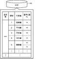
- the HDD 85 stores various information used for mounting on the mounting device 20 and inspection on the inspection device 40. FIG.
- FIG. 3 is an explanatory diagram showing an example of implementation schedule information 86.
- this mounting schedule information 86 for example, regarding a job scheduled to be produced, the number of an area in which the board S is divided into a plurality of parts in association with the board type of the board S, the part type of the part P, and the X direction of the part P Information such as the width, the length in the Y direction, the height in the Z direction, and the arrangement position of the component P is included.
- the information on the arrangement position is, for example, information indicating the XY coordinates of the center of the component P.
- the region in the substrate S is a region in which the substrate S is divided into a plurality of regions based on the imaging range of the substrate camera 53 of the inspection device 40.
- each child substrate may be one region or the like, or each slave substrate may be further divided into a plurality of regions.
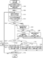
- FIG. 5 is a flowchart showing an example of the inspection-related processing routine.
- This routine is stored in the HDD 45 of the inspection control unit 41 and executed by the CPU 42.
- the CPU 42 first determines whether or not the implementation schedule information has been acquired (S100). It is assumed that the mounting schedule information is transmitted from the management device 80 to the inspection device 40 at a predetermined timing such as when a job production schedule is created.
- the CPU 42 executes a reference position setting process for setting a reference position Fc, which is a reference for the height of the board camera 53 at the time of image acquisition (S110).
- FIG. 6 is a flowchart showing an example of the reference position setting process.
- the CPU 42 first acquires information on the area where the board S is divided and information on the height of the component P to be mounted from the mounting schedule information (S200), and sets the value 1 in the processing target area N. Is set (S205).
- the CPU 42 obtains distribution statistics such as a histogram of the height of each component P arranged in the region N from the information acquired in S200 (S210), and based on the result, the height of each component P.
- the representative value is determined to be one of the mode value, the midpoint value, the median value, and the average value (S215).
- the CPU 42 determines a representative value according to the number of parts P, which is the number of statistically collected data, the number of parts P, which are outliers in the height distribution, and the importance of inspecting the parts P. And the representative value is determined according to the required inspection accuracy. For example, the CPU 42 determines the mode when the number of data is more than a predetermined number, and determines the mode when the number of data is relatively large, such as determining a value other than the mode when the number of data is less than the predetermined number. ..
- the CPU 42 determines the median value when it is desired to eliminate the influence of outliers from the importance of inspection of the component P, and the midpoint between the maximum height and the minimum height when it is desired to increase the influence of outliers. Determine the value. Further, the CPU 42 determines the average value from the number of outlier parts P when the influence of the outliers is small or there is no problem even if the outliers are included.
- the CPU 42 determines whether or not the representative value is determined to be the mode (S220), and if it is determined to determine the mode, the height of each component P in the region N is determined. Calculate the mode (S225). Subsequently, the CPU 42 determines whether or not the calculated mode value is one (S230), and if the mode value is one, sets the mode value of 1 as the reference position Fc (S230). S235) If the mode is not one but a plurality, each of the plurality of modes is set in the reference position Fc (S240).
- the mode may be a plurality of modes, but the CPU 42 determines a plurality of modes up to a predetermined number (for example, 2 or 3), and makes the number more than the predetermined number. Then, the midpoint value, the median value, and the average value other than the mode may be determined.
- a predetermined number for example, 2 or 3
- the CPU 42 determines whether or not the midpoint value is determined (S245) and whether or not the median value is determined (S250). To do. When the CPU 42 determines that the midpoint value has been determined, it calculates the midpoint value from the maximum height and the minimum height of each component P in the region N and sets the midpoint value at the reference position Fc (S255). Further, when the CPU 42 determines that the median value is determined in S250, the CPU 42 calculates the median value of the height of each component P in the region N and sets the reference position Fc (S260).
- the CPU 42 determines that the midpoint value or the median value is not determined in S245 and S250, that is, the average value is determined, the CPU 42 calculates the average value of the heights of each component P in the region N and sets the reference position Fc. (S265).
- the CPU 42 determines whether or not there is an area in which the reference position Fc is not set (S270). When the CPU 42 determines that there is an unset area, the area N is incremented by 1 (S275), and the process returns to S210. When it is determined that there is no unset area, the CPU 42 ends the reference position setting process.
- the reference position setting process As shown in FIG. 7, for each region in the substrate S of each substrate type, any one of the mode value, the midpoint value, the median value, and the average value is set to the height of each component P.
- the reference position Fc is set as a representative value of, and is stored in the HDD 45. In FIG. 7, two reference positions Fc are set because there are a plurality of modes (two in this case) in the region 5.
- the CPU 42 executes the reference position setting process of S110 or determines that the mounting schedule information has not been acquired in S100, it determines whether or not the substrate S to be inspected to be conveyed from the mounting device 20 has been accepted (S120). ), If it is determined that the substrate S is not accepted, the process returns to S100. On the other hand, when the CPU 42 determines that the substrate S has been accepted, it executes an inspection image imaging process (S130), executes an inspection process using the inspection image (S140), and returns to S100.
- FIG. 8 is a flowchart showing an example of the image imaging process for inspection.
- the CPU 42 first sets the value 1 in the area N (S300), and reads out the reference position Fc of the area N from the HDD 45 among the reference position Fc of the substrate type of the received substrate S (S300). S310).
- the CPU 42 moves the board camera 53 and the board S in the XY directions so that the board camera 53 is located on the area N (S320).
- the CPU 42 drives the Y-direction slider 54a of the moving mechanism 54 so that the substrate camera 53 moves on the region N with the region N as the imaging region.
- the CPU 42 controls the substrate processing unit 50 so that the substrate S moves in the X direction and is fixed.
- the CPU 42 controls the moving mechanism 54 so that the substrate camera 53 moves (elevates) in the Z direction to a height Hc that focuses on the reference position Fc read in S310 (S330). That is, the CPU 42 drives the Z-direction slider 54b of the moving mechanism 54 so that the board camera 53 moves up and down at a height Hc.
- the CPU 42 captures an inspection image with the substrate camera 53 (S340), and determines whether or not there are a plurality of reference position Fcs in the region N this time (S350). For example, in the case of region 5 of FIG. 7, when the CPU 42 determines that there are a plurality of reference position Fcs, it determines whether or not there is an unimaged reference position Fc (S360), and if there is an unimaged reference position Fc. If it is determined, the process returns to S330 and processing is performed. Therefore, since the inspection image is imaged at the height Hc corresponding to each reference position Fc, a plurality of inspection images are imaged in one region.
- the CPU 42 determines whether or not there is an unimaged region (S370).
- the region N is incremented by 1 (S380), returns to S310, and performs processing.
- the CPU 42 ends the inspection image imaging process. .. By executing this inspection image imaging process, inspection images are imaged for each region of the substrate S, and a plurality of inspection images are captured in the regions where a plurality of reference positions Fc are set.
- the inspection process uses each inspection image to inspect the component P.
- the CPU 42 can grasp which height Hc the inspection image is captured in a state without blur according to the height of each component P, and is suitable for each component P. The inspection can be performed accurately using the inspection image.
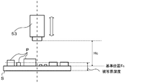
- FIG. 9 is an explanatory diagram showing a reference position Fc of a comparative example
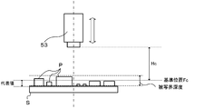
- FIG. 10 is an explanatory diagram showing a reference position Fc of the present embodiment.
- the reference position Fc is set on the upper surface of the substrate S
- a representative value such as an average value of the heights of the parts P is set as the reference position Fc. Show things.
- the upper surface which is the imaging surface of some parts P, may deviate from the depth of field. In that case, an inspection image in which the upper surface of each component P is blurred may be captured and the inspection accuracy may decrease.
- the reference position Fc is set according to the height of each component P instead of the upper surface of the substrate S, and the substrate camera 53 is moved up and down to the height Hc based on the reference position Fc.
- an inspection image can be imaged with the upper surfaces of the plurality of components P within the depth of field. Therefore, since the upper surface of each component P can be copied to the inspection image without blurring, the inspection accuracy can be improved. Further, in order to focus on each of the upper surfaces of the plurality of parts P, it is not necessary to repeatedly image the inspection image at a height Hc corresponding to each of the heights of the plurality of parts P, so that the inspection image is captured. It takes a lot of time to prevent the inspection time from becoming long.
- the inspection device 40 of the present embodiment corresponds to the inspection device of the present disclosure
- the substrate camera 53 corresponds to the camera
- the moving mechanism 54 corresponds to the elevating mechanism
- the CPU 42 of the inspection control unit 41 that performs the position setting process corresponds to the setting unit
- the CPU 42 of the inspection control unit 41 that performs the inspection image imaging process of the inspection-related processing routine S130 corresponds to the control unit.
- an example of the method of capturing the inspection image of the present disclosure is also clarified by explaining the operation of the inspection device 40.
- the reference position Fc is set based on the representative value of the height of each component P so that the upper surface of each component P fits within the depth of field of the fixed focus type substrate camera 53.
- the substrate camera 53 is moved up and down to a height Hc that focuses on the reference position Fc, and then an inspection image is taken.
- the inspection images of the plurality of components P mounted on the substrate S can be quickly captured by the substrate camera 53 to enable rapid inspection.
- the upper surface of each component P can be imaged with as little blur as possible, the inspection accuracy can be improved.
- the reference position Fc can be quickly set by a simple setting method using any of the mode value, the midpoint value, the median value, and the average value as the representative value of the height of each component P. Further, since a plurality of reference position Fcs are set using each of the plurality of modes, an appropriate reference position Fc is set according to each mode, and the upper surface of each component P is more appropriately inspected. The inspection accuracy can be improved by copying to. Further, since the substrate S of 1 is divided into a plurality of regions and the reference position Fc is set by a different setting method for each region, an appropriate reference position Fc is set even when the tendency of the height of the component P is different for each region. The inspection accuracy can be improved.
- FIG. 11 is a flowchart showing an inspection-related processing routine of a modified example.
- the same process as that of the above-described embodiment is assigned the same step number, and detailed description thereof will be omitted.
- the inspection-related processing routine of the modified example when the CPU 42 determines that the substrate S to be inspected has been accepted in S120, the CPU 42 acquires the mounting record information of the substrate S from the management device 80 (S122).
- the mounting device 20 transmits the board ID (identification information) of the board S and the mounting status of the component P on the board S to the management device 80 each time the mounting process of the board S of 1 is completed. Further, if there is a component P that could not be mounted on the board S as scheduled due to an error or the like, that is, a component P that has not been mounted, the mounting device 20 transmits information such as a component type and an arrangement position of the component P to the management device 80. To do.
- the management device 80 associates such information with the board ID of the board S and stores it in the HDD 85 as mounting record information.
- the CPU 42 acquires the mounting record information in S122, it determines whether or not there is an unmounted component P in the received board S (S124).
- the CPU 42 determines that there is an unmounted component P, it executes the reference position resetting process of FIG. 12 (S126), proceeds to the process of S130, and skips S126 when it determines that there is no unmounted component P. Then proceed to the processing of S130.
- the CPU 42 In the reference position resetting process of FIG. 12 (S126), the CPU 42 first acquires information on the component type of the unmounted component P and the area including the arrangement position from the mounting record information (S200b). In the reference position resetting process, the CPU 42 resets the reference position Fc of the region acquired in S200b. Therefore, the CPU 42 sequentially sets the acquired area to the area N that needs to be reset (S205b), and the height of each component P other than the unmounted component P in the area N, that is, the mounted component P. The information and the information on whether the representative value in the region N is any of the mode value, the midpoint value, the median value, and the average value are acquired (S212).
- the CPU 42 performs the processes of S220 to S265 using the height of each mounted component P other than the unmounted component P to reset the reference position Fc. Subsequently, the CPU 42 determines whether or not there is another reset area (S270b), and if it determines that there is another reset area, returns to S205b and performs a return process, and determines that there is no other reset area. Then, the reference position resetting process ends.
- an appropriate reference position Fc is reset from the height of the mounted component P excluding the component P. Therefore, it is possible to take an inspection image more suitable for the actual mounting state of the component P, so that the inspection accuracy can be improved.
- the statistics of the height distribution of each mounted component P are retaken except for the unmounted component P in the region N, and based on the result, the representative value is set to the mode and the midpoint.
- the reference position Fc may be reset after determining the value, the median value, or the average value. In this way, the reference position Fc that is more suitable for the height tendency of each mounted component P can be set again, excluding the unmounted component P.
- different reference position Fc can be set in each region of the substrate S, but the present invention is not limited to this, and a common reference position Fc can be set in each region of the substrate S.
- the reference position Fc of may be set.
- a plurality of reference positions Fc are set, but the present invention is not limited to this.
- the mode of any one may be set in the reference position Fc according to the importance of inspection of a plurality of types of parts P corresponding to the mode.
- the mode of any one may be set as the reference position Fc, or the average of the plurality of modes may be set as the reference position Fc. May be good.
- the reference position Fc is set using any of the mode, midpoint, median, and average of the height of each component P, but the reference position Fc is not limited to this, and the height of each component P is not limited to this.
- the reference position Fc may be set using the representative value of the height.
- the representative value is not limited to the mode value, the midpoint value, the median value, and the average value, and the representative value may be determined from any two or three values.
- the representative value may be determined by another method such as a weighted average value weighted on the height of the component P having a relatively high importance of inspection.
- the representative value is not limited to the method for determining the representative value from a plurality of methods, and the representative value may be determined by a method instructed by the operator, or the representative value may be determined by a predetermined method.
- the reference position Fc is not limited to the one using the representative value of the height, and any method can be used. May be used to determine the distance.
- the depth of field differs between the front depth of field in front (on the board camera 53 side) and the rear depth of field behind the position where the focus is strictly focused, and the rear depth of field is usually the front depth of field.
- a value obtained by adding a predetermined value to the representative value of the height of each component P is used. It may be set to the reference position Fc. In this way, it is possible to set a reference position Fc that makes it easier to fit the upper surface of each component P within the depth of field.
- the component P arranged on the upper surface of the substrate S is inspected, but the present invention is not limited to this, and the component P arranged on the lower surface of the substrate S may be inspected. That is, the reference position Fc is set so as to be within the depth of field of the substrate camera 53 so that the imaging surface of each component is separated from the surface (arrangement surface) of the substrate S by a distance corresponding to the height of each component P. Anything is fine.
- the inspection device 40 sets the reference position Fc, but the present invention is not limited to this, and the management device 80 may set the reference position Fc and transmit the reference position Fc to the inspection device 40.
- the mounting device 20 includes a fixed focus type camera and an elevating mechanism for raising and lowering the camera in at least the Z direction, and has a function of performing inspection using an image captured by the camera, that is, the mounting device 20 inspects. It may also function as a device. In such a case, the mounting device 20 may set the reference position Fc.
- the inspection device of the present disclosure may be configured as follows.
- the setting unit sets the reference position with the average value of the heights of the parts as the distance, and sets the median height of the parts.
- a method of setting the reference position as the distance a method of setting the reference position with the median value of the height of each component as the distance, and a method of setting the reference position with the mode of the height of each component as the distance. Any of the methods for setting the above may be used. In this way, the reference position separated by the distance corresponding to the height of each component can be quickly set by a relatively simple setting method.
- the setting unit uses a method of setting the reference position using the mode as the predetermined setting method, if a plurality of the modes exist, the plurality of the modes are used.
- a plurality of the reference positions are set using the mode values of the above, and the control unit controls the elevating mechanism and the camera so as to capture the inspection image at each of the plurality of reference positions. It may be a thing.
- an appropriate reference position can be set according to each mode, so that the imaging surface of each component is more appropriately copied to the inspection image for inspection. The accuracy can be improved.
- the setting unit divides one of the substrates into a plurality of regions, and the setting method differs for each region based on the height information of the parts arranged in each of the divided regions.
- the reference position may be set according to the above. By doing so, even if the tendency of the height of the component is different for each area of the substrate, an appropriate reference position can be set for each area, so that the imaging surface of each component can be more appropriately copied to the inspection image for inspection. The accuracy can be improved.
- the setting unit is scheduled to be arranged on the substrate after acquiring height information of the plurality of parts to be arranged on the substrate and setting the reference position in advance.
- the reference position may be reset according to the height of the other parts excluding the part.
- the method of capturing the inspection image of the present disclosure is It is a method of capturing an inspection image by capturing an inspection image of a substrate on which a plurality of parts are arranged by a fixed focus type camera.
- A The height information of the plurality of parts is acquired, and the imaging surface of each component within the imaging range of the camera is within the depth of field of the camera, so that the substrate can be set by a predetermined setting method.
- B A step of raising and lowering the camera relative to the substrate so as to focus on the reference position, and then taking an image for inspection.
- the gist is to include.
- the imaging surface of each component within the imaging range of the camera can be projected on the inspection image of 1, so that the inspection image can be quickly captured. It can be imaged.
- various aspects of the inspection device may be adopted, or steps may be added to realize each function of the inspection device.
- This disclosure can be used in the technical field of inspecting a substrate on which components are arranged.
- 10 component mounting system 12 LAN, 20 mounting device, 40 inspection device, 40a base, 41 inspection control unit, 42 CPU, 43 ROM, 44 RAM, 45 HDD, 50 board processing unit, 52 inspection processing unit, 53 board camera , 54 movement mechanism, 54a Y direction slider, 54b Z direction slider, 55 frame, 55a beam part, 56 operation panel, 57 display screen, 58 operation buttons, 59 input / output interface, 80 management device, 81 control device, 82 CPU, 83 ROM, 84 RAM, 85 HDD, 86 mounting schedule information, 87 input device, 88 display, 89 input / output interface, P parts, S board.
Landscapes
- Engineering & Computer Science (AREA)
- Multimedia (AREA)
- Signal Processing (AREA)
- Operations Research (AREA)
- Manufacturing & Machinery (AREA)
- Microelectronics & Electronic Packaging (AREA)
- Length Measuring Devices By Optical Means (AREA)
- Supply And Installment Of Electrical Components (AREA)
- Investigating Materials By The Use Of Optical Means Adapted For Particular Applications (AREA)
Abstract
複数の部品が配置された基板の検査用画像を用いて検査を行う検査装置は、固定焦点型のカメラと、カメラを基板に対して相対的に昇降させる昇降機構と、複数の部品の高さ情報を取得し、カメラの撮像範囲内にある各部品の撮像面がカメラの被写界深度内に収まるように、所定の設定手法により基板の表面から各部品の高さに応じた距離だけ離れた基準位置を設定する設定部と、基準位置に焦点が合うようにカメラを相対的に昇降させてから検査用画像を撮像するように、昇降機構とカメラとを制御する制御部と、を備える。
Description
本明細書は、検査装置および検査用画像の撮像方法を開示する。
従来、基板に実装された部品の実装状態を検査用画像を用いて検査する検査装置が提案されている(例えば、特許文献1参照)。この検査装置は、焦点距離が一定の距離に固定された固定焦点型のカメラを、垂直移動可能に構成する。また、検査装置は、基板に実装された部品のそれぞれの高さ(厚み)を抽出してカメラの目的の高さ位置を設定し、その高さ位置にカメラを垂直移動させることで焦点を合わせて検査用画像を撮像している。
上述した検査装置では、基板に実装された部品の1つ1つの高さに応じて、カメラを垂直移動させて高さ位置を調整するため、高さ位置の調整回数が増えることになる。このため、検査用画像の撮像に時間を要し、迅速な検査を行うことが困難となる。
本開示は、基板に実装された複数の部品の検査用画像を、固定焦点型のカメラで速やかに撮像することにより、迅速な検査を可能とすることを主目的とする。
本開示は、上述の主目的を達成するために以下の手段を採った。
本開示の検査装置は、
複数の部品が配置された基板の検査用画像を用いて検査を行う検査装置であって、
固定焦点型のカメラと、
前記カメラを前記基板に対して相対的に昇降させる昇降機構と、
前記複数の部品の高さ情報を取得し、前記カメラの撮像範囲内にある各部品の撮像面が前記カメラの被写界深度内に収まるように、所定の設定手法により前記基板の表面から前記各部品の高さに応じた距離だけ離れた基準位置を設定する設定部と、
前記基準位置に焦点が合うように前記カメラを相対的に昇降させてから前記検査用画像を撮像するように、前記昇降機構と前記カメラとを制御する制御部と、
を備えることを要旨とする。
複数の部品が配置された基板の検査用画像を用いて検査を行う検査装置であって、
固定焦点型のカメラと、
前記カメラを前記基板に対して相対的に昇降させる昇降機構と、
前記複数の部品の高さ情報を取得し、前記カメラの撮像範囲内にある各部品の撮像面が前記カメラの被写界深度内に収まるように、所定の設定手法により前記基板の表面から前記各部品の高さに応じた距離だけ離れた基準位置を設定する設定部と、
前記基準位置に焦点が合うように前記カメラを相対的に昇降させてから前記検査用画像を撮像するように、前記昇降機構と前記カメラとを制御する制御部と、
を備えることを要旨とする。
本開示の検査装置は、カメラの撮像範囲内にある各部品の撮像面がカメラの被写界深度内に収まるように、所定の設定手法により基板の表面から各部品の高さに応じた距離だけ離れた基準位置を設定する。そして、基準位置に焦点が合うように、基板に対してカメラを相対的に昇降させてから検査用画像を撮像する。これにより、1の検査用画像にカメラの撮像範囲内にある各部品の撮像面を写し出すことができるから、各部品の撮像面にそれぞれ焦点が合うようにカメラを昇降させて各部品の検査用画像を撮像するものに比して、検査用画像を速やかに撮像することができる。したがって、基板に実装された複数の部品の検査用画像を、固定焦点型のカメラで速やかに撮像することにより、迅速な検査を可能とすることができる。
次に、本開示を実施するための形態を図面を参照しながら説明する。図1は部品実装システム10の一例を示す説明図であり、図2は検査装置40の基板カメラ53と移動機構54の構成の概略を示す説明図である。
部品実装システム10は、図1に示すように、リールやトレイなどから部品Pを採取して基板S上に実装する実装装置20と、複数の部品Pが実装された基板Sを検査する検査装置40と、実装装置20や検査装置40に関する情報を管理する管理装置80とを備える。実装装置20と検査装置40と管理装置80とは、ネットワークとしてのLAN12に接続されており、互いに情報をやり取り可能である。なお、図1では、実装装置20と検査装置40とを1台ずつ図示するが、実装装置20や検査装置40を複数台備えてもよい。本実施形態において、左右方向(X軸)、前後方向(Y軸)および上下方向(Z軸)は、図1に示す通りとする。また、「実装」とは、部品Pを基板S上に配置、装着、挿入、接合、接着することなどを含む。
検査装置40は、各種制御を実行する検査制御ユニット41と、部品Pが実装された基板SのX方向への搬送と固定とを実行する基板処理ユニット50と、基板Sの検査時に検査用画像の撮像処理などを実行する検査処理ユニット52とを備える。また、検査装置40は、各種情報の表示と作業者による各種入力操作とが可能な操作パネル56と、通信を行うための入出力インタフェース(I/F)59とを備える。
検査処理ユニット52は、基板S上の基板IDや基板S上に配置された複数の部品Pを含む検査用画像を撮像する基板カメラ53と、基板カメラ53をY方向およびZ方向に移動させる移動機構54とを備える。基板カメラ53は、光学系の焦点距離が固定された固定焦点型のカメラとして構成され、図示は省略するが、基板Sに光を照射する照明部と、受光により発生した電荷を出力する撮像素子と、出力された電荷に基づいて画像データを生成する画像処理部とを備える。図2に示すように、検査装置40の基台40aには、基板処理ユニット50により搬送される基板Sを跨ぐように配置された門型のフレーム55が固定されている。移動機構54は、フレーム55の梁部55aにY方向に移動可能に取り付けられたY方向スライダ54aと、Y方向スライダ54aにZ方向に移動可能に取り付けられたZ方向スライダ54bとを備える。基板カメラ53は、Z方向スライダ54bに固定されており、Y方向スライダ54aの移動やZ方向スライダ54bの移動に伴って基板カメラ53がY方向に移動したりZ方向に移動(昇降)したりする。各スライダは、それぞれ駆動モータにより駆動される。なお、基板Sは、基板処理ユニット50によりX方向に移動して、X方向における所定範囲が基板カメラ53の下方に位置するように固定される。検査処理ユニット52は、基板Sが固定された状態で、移動機構54により基板カメラ53をY方向へ移動させて撮像範囲を合わせると共に固定の焦点距離に応じたZ方向の高さ位置へ基板カメラ53を移動させて焦点を合わせてから、基板カメラ53により検査用画像を撮像する。なお、基板カメラ53は、厳密に焦点が合う焦点距離に上面(撮像面)が位置する部品Pだけでなく、焦点が合っているように見える被写界深度内に上面が位置する部品Pであれば、ボケのない状態で検査用画像に写すことができる。
操作パネル56は、各種情報を表示する表示画面57と、作業者の入力操作を受け付ける操作ボタン58とを備える。表示画面57は、液晶ディスプレイとして構成されており、検査装置40の検査情報や設定情報、画像などを表示する。操作ボタン58は、表示画面57中の選択カーソルを上下左右に移動させるカーソルボタン、選択内容を決定する決定ボタン、入力をキャンセルするキャンセルボタンなどを備える。
検査制御ユニット41は、CPU42を中心とするマイクロプロセッサとして構成されており、処理プログラムを記憶するROM43、作業領域として用いられるRAM44、各種データを記憶するHDD45などを備え、これらはバスを介して接続されている。検査制御ユニット41は、入出力インタフェース59を介して、基板処理ユニット50や検査処理ユニット52の移動機構54へ制御信号を出力したり、検査処理ユニット52の基板カメラ53に撮像信号を出力したり、操作パネル56に表示信号を出力したり、管理装置80へ情報を送信したりする。また、検査制御ユニット41は、入出力インタフェース59を介して、基板処理ユニット50からの信号を入力したり、基板カメラ53が撮像した検査用画像を取得したり、操作パネル56から操作信号を入力したり、管理装置80から情報を受信したりする。
管理装置80は、制御装置81を備え、実装装置20や検査装置40を管理する。制御装置81は、CPU82を中心とするマイクロプロセッサとして構成されており、処理プログラムを記憶するROM83、作業領域として用いられるRAM84、各種データを記憶するHDD85などを備え、これらはバスを介して接続されている。また、管理装置80は、作業者が各種指示を入力するキーボードおよびマウス等の入力装置87と、各種情報を表示するディスプレイ88と、通信を行うための入出力インタフェース(I/F)89とを備える。HDD85には、実装装置20での実装や検査装置40での検査に用いられる各種情報などが記憶されている。図3は実装予定情報86の一例を示す説明図である。この実装予定情報86には、例えば、生産予定のジョブに関し、基板Sの基板種に対応付けて、基板Sを複数に分割した領域の番号と、部品Pの部品種別、部品PのX方向の幅とY方向の長さとZ方向の高さなどのサイズ、部品Pの配置位置などの情報が含まれている。なお、配置位置の情報は、例えば部品Pの中心のXY座標を示す情報である。また、基板S内の領域は、検査装置40の基板カメラ53の撮像範囲に基づいて基板Sを複数に分割した領域などとする。図4は基板Sを複数の領域に分割した一例を示す説明図である。図示するように、基板S内を縦横に区切ることで複数の領域(図4では領域1~6)に分割するものとした。なお、基板Sが複数の子基板を有する多面取り基板である場合、各子基板を1の領域などとしてもよいし、各子基板をさらに複数の領域に分けてもよい。
以下は、検査装置40の動作、特に、複数の部品Pが実装された基板Sの検査に関する動作の説明である。図5は検査関連処理ルーチンの一例を示すフローチャートである。このルーチンは、検査制御ユニット41のHDD45に記憶され、CPU42により実行される。このルーチンが実行されると、CPU42は、まず、実装予定情報を取得したか否かを判定する(S100)。実装予定情報は、例えば、ジョブの生産予定が作成された際などの所定タイミングで管理装置80から検査装置40に送信されるものとする。CPU42は、実装予定情報を取得したと判定すると、画像撮像時の基板カメラ53の高さの基準となる基準位置Fcを設定する基準位置設定処理を実行する(S110)。
図6は基準位置設定処理の一例を示すフローチャートである。基準位置設定処理では、CPU42は、まず、実装予定情報から基板Sを分割した領域の情報と実装予定の部品Pの高さの情報とを取得し(S200)、処理対象の領域Nに値1をセットする(S205)。次に、CPU42は、S200で取得した情報から領域N内に配置される各部品Pの高さのヒストグラムなど分布の統計を取り(S210)、その結果に基づいて、各部品Pの高さの代表値を最頻値、中点値、中央値、平均値のいずれかに決定する(S215)。S215では、CPU42は、統計を取ったデータ数である部品Pの数に応じて代表値を決定したり、高さの分布で外れ値となる部品Pの数やその部品Pの検査の重要度や要求される検査精度に応じて代表値を決定したりする。例えば、CPU42は、データ数が所定数以上の場合に最頻値に決定し、所定数未満の場合に最頻値以外に決定するなど、データ数が比較的多い場合に最頻値に決定する。また、CPU42は、部品Pの検査の重要度などから、外れ値の影響を除きたい場合に中央値に決定し、外れ値の影響を高めたい場合に最大高さと最小高さの中間の中点値に決定する。また、CPU42は、外れ値となる部品Pの数から、外れ値の影響が小さかったり外れ値が含まれても問題ない場合には、平均値に決定する。
こうして代表値を決定すると、CPU42は、代表値を最頻値に決定したか否かを判定し(S220)、最頻値に決定したと判定すると、領域N内の各部品Pの高さの最頻値を演算する(S225)。続いて、CPU42は、演算した最頻値が1つであるか否かを判定し(S230)、最頻値が1つであれば、その1の最頻値を基準位置Fcに設定し(S235)、最頻値が1つでなく複数であれば、複数の最頻値をそれぞれ基準位置Fcに設定する(S240)。高さの分布の傾向によっては最頻値が複数になるが、CPU42は、最頻値が所定個数(例えば2個や3個など)までは複数の最頻値に決定し、所定個数以上になると最頻値以外の中点値や中央値,平均値に決定するものなどとしてもよい。
また、CPU42は、S220で代表値を最頻値に決定していないと判定すると、中点値に決定したか否か(S245)、中央値に決定したか否か(S250)、をそれぞれ判定する。CPU42は、中点値に決定したと判定すると、領域N内の各部品Pの最大高さと最小高さから中点値を演算して基準位置Fcに設定する(S255)。また、CPU42は、S250で中央値に決定したと判定すると、領域N内の各部品Pの高さの中央値を演算して基準位置Fcに設定する(S260)。また、CPU42は、S245,S250で中点値や中央値ではない、即ち平均値に決定したと判定すると、領域N内の各部品Pの高さの平均値を演算して基準位置Fcに設定する(S265)。
こうして基準位置Fcを設定すると、CPU42は、基準位置Fcを未設定の領域があるか否かを判定する(S270)。CPU42は、未設定の領域があると判定すると、領域Nを値1インクリメントして(S275)、S210に戻り処理を行い、未設定の領域がないと判定すると、基準位置設定処理を終了する。基準位置設定処理の実行により、図7に示すように、各基板種の基板S内の領域毎に、最頻値や中点値、中央値、平均値のいずれかを各部品Pの高さの代表値として基準位置Fcが設定されて、HDD45に記憶されることになる。なお、図7では、領域5において、最頻値が複数(ここでは2つ)あったために、2つの基準位置Fcが設定されている。
CPU42は、S110の基準位置設定処理を実行するか、S100で実装予定情報を取得してないと判定すると、実装装置20から搬送される検査対象の基板Sを受け入れたか否かを判定し(S120)、基板Sを受け入れてないと判定するとS100に戻る。一方、CPU42は、基板Sを受け入れたと判定すると、検査用画像撮像処理を実行し(S130)、検査用画像を用いた検査処理を実行して(S140)、S100に戻る。
図8は検査用画像撮像処理の一例を示すフローチャートである。検査用画像撮像処理では、CPU42は、まず、領域Nに値1をセットして(S300)、受け入れた基板Sの基板種の基準位置Fcのうち、領域Nの基準位置FcをHDD45から読み出す(S310)。次に、CPU42は、領域N上に基板カメラ53が位置するように基板カメラ53と基板SとをXY方向に移動させる(S320)。S320では、CPU42は、領域Nを撮像領域として、その領域N上に基板カメラ53が移動するように移動機構54のY方向スライダ54aを駆動させる。また、CPU42は、必要であれば、基板SがX方向に移動して固定されるように基板処理ユニット50を制御する。次に、CPU42は、S310で読み出した基準位置Fcに焦点が合う高さHcに基板カメラ53がZ方向に移動(昇降)するように移動機構54を制御する(S330)。即ち、CPU42は、高さHcに基板カメラ53が昇降するように移動機構54のZ方向スライダ54bを駆動させる。
次に、CPU42は、基板カメラ53により検査用画像を撮像し(S340)、今回の領域Nの基準位置Fcが複数あるか否かを判定する(S350)。例えば、図7の領域5の場合など、CPU42は基準位置Fcが複数あると判定すると、未撮像の基準位置Fcがあるか否かを判定し(S360)、未撮像の基準位置Fcがあると判定すると、S330に戻り処理を行う。このため、各基準位置Fcに応じた高さHcでそれぞれ検査用画像が撮像されるから、1の領域で複数の検査用画像が撮像されることになる。CPU42は、S350で基準位置Fcが複数ないと判定したり、S360で未撮像の基準位置Fcがないと判定したりすると、未撮像の領域があるか否かを判定する(S370)。CPU42は、未撮像の領域があると判定すると、領域Nを値1インクリメントして(S380)、S310に戻り処理を行い、未撮像の領域がないと判定すると、検査用画像撮像処理を終了する。この検査用画像撮像処理の実行により、基板Sの領域毎に、それぞれ検査用画像が撮像され、複数の基準位置Fcが設定された領域では複数枚の検査用画像が撮像される。なお、1の領域に複数枚の検査用画像が撮像された場合、検査処理では各検査用画像を用いて部品Pの検査が行われる。その際、CPU42は、各部品Pの高さに応じて、いずれの高さHcで撮像された検査用画像であればボケのない状態で写っているかを把握できるから、部品P毎に適した検査用画像を用いて検査を精度よく行うことができる。
ここで、図9は比較例の基準位置Fcを示す説明図であり、図10は本実施形態の基準位置Fcを示す説明図である。図9の比較例では、基準位置Fcを基板Sの上面に設定するものを示し、図10の本実施形態では、例えば部品Pの高さの平均値などの代表値を基準位置Fcに設定するものを示す。比較例では、基準位置Fcを基板Sの上面に設定するため、一部の部品Pの撮像面である上面が被写界深度から外れる場合がある。その場合、各部品Pの上面がボケた状態の検査用画像が撮像されて検査精度が低下するおそれがある。これに対して、本実施形態では、基板Sの上面ではなく、各部品Pの高さに応じた基準位置Fcを設定し、その基準位置Fcに基づく高さHcに基板カメラ53を昇降させるから、図10に示すように、複数の部品Pの上面を被写界深度内に収めた状態で検査用画像を撮像することができる。このため、各部品Pの上面をボケのない状態で検査用画像に写すことができるから、検査精度を向上させることができる。また、複数の部品Pの上面のそれぞれに焦点を合わせるために、複数の部品Pの高さのそれぞれに応じた高さHcで検査用画像を繰り返し撮像する必要もないから、検査用画像の撮像に多くの時間がかかって検査時間が長くなるのを防止することができる。
ここで、本実施形態の構成要素と本開示の構成要素との対応関係を明らかにする。本実施形態の検査装置40が本開示の検査装置に相当し、基板カメラ53がカメラに相当し、移動機構54(Z方向スライダ54b)が昇降機構に相当し、検査関連処理ルーチンのS110の基準位置設定処理を行う検査制御ユニット41のCPU42が設定部に相当し、検査関連処理ルーチンのS130の検査用画像撮像処理を行う検査制御ユニット41のCPU42が制御部に相当する。なお、本実施形態では、検査装置40の動作を説明することにより本開示の検査用画像の撮像方法の一例も明らかにしている。
以上説明した検査装置40では、固定焦点型の基板カメラ53の被写界深度内に各部品Pの上面が収まるように、各部品Pの高さの代表値に基づいて基準位置Fcを設定し、基準位置Fcに焦点が合う高さHcに基板カメラ53を昇降させてから検査用画像を撮像する。これにより、基板Sに実装された複数の部品Pの検査用画像を、基板カメラ53で速やかに撮像して迅速な検査を可能とすることができる。また、各部品Pの上面をできるだけボケのない状態で撮像することができるから、検査精度を向上させることができる。
また、各部品Pの高さの代表値として最頻値、中点値、中央値、平均値のいずれかを用いる簡易な設定手法で、基準位置Fcを速やかに設定することができる。また、複数の最頻値をそれぞれ用いて複数の基準位置Fcを設定するから、それぞれの最頻値に応じた適切な基準位置Fcを設定し、各部品Pの上面をより適切に検査用画像に写して検査精度を向上させることができる。また、1の基板Sを複数の領域に分割し、領域毎に異なる設定手法で基準位置Fcを設定するから、領域毎に部品Pの高さの傾向が異なる場合でも適切な基準位置Fcを設定して検査精度を向上させることができる。
なお、本開示は上述した実施形態に何ら限定されることはなく、本開示の技術的範囲に属する限り種々の態様で実施し得ることはいうまでもない。
例えば、上述した実施形態では、実装予定情報を取得した際に予め設定した基準位置Fcを用いて検査用画像を撮像したが、これに限られるものではない。図11は、変形例の検査関連処理ルーチンを示すフローチャートである。変形例では、上述した実施形態と同じ処理には同じステップ番号を付して詳細な説明は省略する。変形例の検査関連処理ルーチンでは、CPU42は、S120で検査対象の基板Sを受け入れたと判定すると、その基板Sの実装実績情報を管理装置80から取得する(S122)。なお、実装装置20は、1の基板Sの実装処理が完了する度に、基板Sの基板ID(識別情報)と、その基板Sへの部品Pの実装状況とを管理装置80に送信する。また、実装装置20は、エラーなどにより基板Sに予定通りに実装できなかった部品P即ち未実装の部品Pがあれば、その部品Pの部品種や配置位置などの情報を管理装置80に送信する。管理装置80は、それらの情報を基板Sの基板IDに対応付けて実装実績情報としてHDD85に記憶しておく。CPU42は、S122でその実装実績情報を取得すると、受け入れた基板Sに未実装の部品Pがあるか否かを判定する(S124)。CPU42は、未実装の部品Pがあると判定すると図12の基準位置再設定処理を実行してから(S126)、S130の処理に進み、未実装の部品Pがないと判定するとS126をスキップしてS130の処理に進む。
図12(S126)の基準位置再設定処理では、CPU42は、まず、実装実績情報から、未実装の部品Pの部品種とその配置位置が含まれる領域の情報とを取得する(S200b)。基準位置再設定処理では、CPU42は、S200bで取得した領域の基準位置Fcを再設定することになる。このため、CPU42は、取得した領域を再設定が必要な領域Nに順に設定し(S205b)、その領域Nにおける未実装の部品P以外の他の部品P、即ち実装済みの各部品Pの高さの情報と、その領域Nにおける代表値が最頻値や中点値、中央値、平均値のいずれかであるかの情報とを取得する(S212)。そして、CPU42は、未実装の部品P以外の実装済みの各部品Pの高さを用いてS220~S265の処理を行って基準位置Fcを設定し直す。続いて、CPU42は、他の再設定領域があるか否かを判定し(S270b)、他の再設定領域があると判定すると、S205bに戻り処理を行い、他の再設定領域がないと判定すると、基準位置再設定処理を終了する。このように、変形例では、実装されなかった部品Pがある場合、その部品Pを除いた実装済みの部品Pの高さから、適切な基準位置Fcを設定し直すのである。このため、部品Pの実際の実装状況により適した検査用画像を撮像することができるから、検査精度を向上させることができる。なお、この変形例において、領域Nにおける未実装の部品Pを除いて、実装済みの各部品Pの高さの分布の統計を取り直し、その結果に基づいて、代表値を最頻値、中点値、中央値、平均値のいずれかに決定した上で、基準位置Fcを設定し直すものとしてもよい。こうすれば、未実装の部品Pを除いて、実装済みの各部品Pの高さの傾向により適した基準位置Fcを設定し直すことができる。
上述した実施形態では、基板Sの各領域で異なる基準位置Fcを設定可能としたが、これに限られず、基板Sの各領域で共通の基準位置Fcを設定するなど、基板Sに対して1の基準位置Fcを設定してもよい。また、最頻値が複数ある場合に複数の基準位置Fcを設定したが、これに限られるものではない。例えば、最頻値に該当する複数種の部品Pの検査の重要度などに応じて、いずれか1の最頻値を基準位置Fcに設定してもよい。あるいは、複数の最頻値が比較的近い値であれば、いずれか1の最頻値を基準位置Fcに設定してもよいし、複数の最頻値の平均を基準位置Fcに設定してもよい。
上述した実施形態では、各部品Pの高さの最頻値、中点値、中央値、平均値のうちいずれかを用いて基準位置Fcを設定したが、これに限られず、各部品Pの高さの代表値を用いて基準位置Fcを設定すればよい。例えば、最頻値、中点値、中央値、平均値の4つから代表値を決定するものに限られず、いずれか2つまたは3つから代表値を決定してもよいし、これら以外に、例えば検査の重要度などが比較的高い部品Pの高さに重み付けした重み付け平均値など別の手法で代表値を決定してもよい。あるいは、複数の手法のうちから代表値を決定するものに限られず、作業者が指示した手法で代表値を決定してもよいし、予め定められた手法で代表値を決定してもよい。また、基準位置Fcは、各部品Pの高さに応じた距離だけ基板Sの上面から離れた距離に設定されるものであれば、高さの代表値を用いるものに限られず、如何なる手法を用いて距離を決定してもよい。例えば被写界深度は、厳密に焦点が合う位置よりも前方(基板カメラ53側)の前方被写界深度と後方の後方被写界深度とが異なり、通常は後方被写界深度が前方被写界深度の2倍程度となる。このため、基板カメラ53の被写界深度と、前方被写界深度および後方被写界深度との比率とを考慮して、各部品Pの高さの代表値に所定値を加えた値を基準位置Fcに設定するものなどとしてもよい。こうすれば、各部品Pの上面を被写界深度内により収めやすい基準位置Fcを設定することができる。
上述した実施形態では、基板Sの上面に配置された部品Pを検査したが、これに限られず、基板Sの下面に配置された部品Pを検査するものなどとしてもよい。即ち、各部品の撮像面が基板カメラ53の被写界深度内に収まるように、基板Sの表面(配置面)から各部品Pの高さに応じた距離だけ離れた基準位置Fcを設定するものであればよい。
上述した実施形態では、検査装置40が基準位置Fcを設定したが、これに限られず、管理装置80が基準位置Fcを設定して検査装置40に送信してもよい。また、実装装置20が、固定焦点型のカメラと、少なくともZ方向にカメラを昇降させる昇降機構とを備え、カメラで撮像した画像を用いて検査を行う機能を備えるもの、即ち実装装置20が検査装置としても機能するものとしてもよい。そのようにする場合、実装装置20が、基準位置Fcを設定してもよい。
ここで、本開示の検査装置は、以下のように構成してもよい。本開示の検査装置において、前記設定部は、前記所定の設定手法として、前記各部品の高さの平均値を前記距離として前記基準位置を設定する手法、前記各部品の高さの中央値を前記距離として前記基準位置を設定する手法、前記各部品の高さの中点値を前記距離として前記基準位置を設定する手法、前記各部品の高さの最頻値を前記距離として前記基準位置を設定する手法のいずれかを用いるものとしてもよい。こうすれば、各部品の高さに応じた距離だけ離れた基準位置を、比較的簡易な設定手法で速やかに設定することができる。
本開示の検査装置において、前記設定部は、前記所定の設定手法として、前記最頻値を用いて前記基準位置を設定する手法を用いる際、前記最頻値が複数存在する場合には該複数の最頻値をそれぞれ用いて複数の前記基準位置を設定し、前記制御部は、複数の前記基準位置のそれぞれで前記検査用画像を撮像するように、前記昇降機構と前記カメラとを制御するものとしてもよい。こうすれば、最頻値が複数算出された場合にそれぞれの最頻値に応じた適切な基準位置を設定することができるから、各部品の撮像面をより適切に検査用画像に写して検査精度を向上させることができる。
本開示の検査装置において、前記設定部は、1の前記基板を複数の領域に分割し、該分割した領域毎に配置されている前記部品の高さ情報に基づいて領域毎に異なる前記設定手法により前記基準位置を設定可能であるものとしてもよい。こうすれば、基板の領域毎に部品の高さの傾向が異なる場合でも領域毎に適切な基準位置を設定することができるから、各部品の撮像面をより適切に検査用画像に写して検査精度を向上させることができる。
本開示の検査装置において、前記設定部は、前記基板に配置される予定の前記複数の部品の高さ情報を取得して前記基準位置を予め設定した後に、前記基板に配置される予定の前記複数の部品のうち一部の部品が配置されなかった場合には、前記一部の部品を除いた他の部品の高さに応じて前記基準位置を設定し直すものとしてもよい。こうすれば、基準位置を予め設定しておくことで、検査用画像の撮像を速やかに開始することができる。また、一部の部品が配置されなかった場合には基準位置を設定し直すことで、他の部品の撮像面をより適切に検査用画像に写して検査精度を向上させることができる。
本開示の検査用画像の撮像方法は、
固定焦点型のカメラにより、複数の部品が配置された基板の検査用画像を撮像する検査用画像の撮像方法であって、
(a)前記複数の部品の高さ情報を取得し、前記カメラの撮像範囲内にある各部品の撮像面が前記カメラの被写界深度内に収まるように、所定の設定手法により前記基板の表面から前記各部品の高さに応じた距離だけ離れた基準位置を設定するステップと、
(b)前記基準位置に焦点が合うように前記基板に対して前記カメラを相対的に昇降させてから前記検査用画像を撮像するステップと、
を含むことを要旨とする。
固定焦点型のカメラにより、複数の部品が配置された基板の検査用画像を撮像する検査用画像の撮像方法であって、
(a)前記複数の部品の高さ情報を取得し、前記カメラの撮像範囲内にある各部品の撮像面が前記カメラの被写界深度内に収まるように、所定の設定手法により前記基板の表面から前記各部品の高さに応じた距離だけ離れた基準位置を設定するステップと、
(b)前記基準位置に焦点が合うように前記基板に対して前記カメラを相対的に昇降させてから前記検査用画像を撮像するステップと、
を含むことを要旨とする。
本開示の検査用画像の撮像方法では、上述した検査装置と同様に、1の検査用画像にカメラの撮像範囲内にある各部品の撮像面を写し出すことができるから、検査用画像を速やかに撮像することができる。なお、検査用画像の撮像方法において、検査装置の種々の態様を採用してもよいし、検査装置の各機能を実現するようなステップを追加してもよい。
本開示は、部品が配置された基板を検査する技術分野などに利用可能である。
10 部品実装システム、12 LAN、20 実装装置、40 検査装置、40a 基台、41 検査制御ユニット、42 CPU、43 ROM、44 RAM、45 HDD、50 基板処理ユニット、52 検査処理ユニット、53 基板カメラ、54 移動機構、54a Y方向スライダ、54b Z方向スライダ、55 フレーム、55a 梁部、56 操作パネル、57 表示画面、58 操作ボタン、59 入出力インタフェース、80 管理装置、81 制御装置、82 CPU、83 ROM、84 RAM、85 HDD、86 実装予定情報、87 入力装置、88 ディスプレイ、89 入出力インタフェース、P 部品、S 基板。
Claims (6)
- 複数の部品が配置された基板の検査用画像を用いて検査を行う検査装置であって、
固定焦点型のカメラと、
前記カメラを前記基板に対して相対的に昇降させる昇降機構と、
前記複数の部品の高さ情報を取得し、前記カメラの撮像範囲内にある各部品の撮像面が前記カメラの被写界深度内に収まるように、所定の設定手法により前記基板の表面から前記各部品の高さに応じた距離だけ離れた基準位置を設定する設定部と、
前記基準位置に焦点が合うように前記カメラを相対的に昇降させてから前記検査用画像を撮像するように、前記昇降機構と前記カメラとを制御する制御部と、
を備える検査装置。 - 請求項1に記載の検査装置であって、
前記設定部は、前記所定の設定手法として、前記各部品の高さの平均値を前記距離として前記基準位置を設定する手法、前記各部品の高さの中央値を前記距離として前記基準位置を設定する手法、前記各部品の高さの中点値を前記距離として前記基準位置を設定する手法、前記各部品の高さの最頻値を前記距離として前記基準位置を設定する手法のいずれかを用いる
検査装置。 - 請求項2に記載の検査装置であって、
前記設定部は、前記所定の設定手法として、前記最頻値を用いて前記基準位置を設定する手法を用いる際、前記最頻値が複数存在する場合には該複数の最頻値をそれぞれ用いて複数の前記基準位置を設定し、
前記制御部は、複数の前記基準位置のそれぞれで前記検査用画像を撮像するように、前記昇降機構と前記カメラとを制御する
検査装置。 - 請求項2または3に記載の検査装置であって、
前記設定部は、1の前記基板を複数の領域に分割し、該分割した領域毎に配置されている前記部品の高さ情報に基づいて領域毎に異なる前記設定手法により前記基準位置を設定可能である
検査装置。 - 請求項1ないし4のいずれか1項に記載の検査装置であって、
前記設定部は、前記基板に配置される予定の前記複数の部品の高さ情報を取得して前記基準位置を予め設定した後に、前記基板に配置される予定の前記複数の部品のうち一部の部品が配置されなかった場合には、前記一部の部品を除いた他の部品の高さに応じて前記基準位置を設定し直す
検査装置。 - 固定焦点型のカメラにより、複数の部品が配置された基板の検査用画像を撮像する検査用画像の撮像方法であって、
(a)前記複数の部品の高さ情報を取得し、前記カメラの撮像範囲内にある各部品の撮像面が前記カメラの被写界深度内に収まるように、所定の設定手法により前記基板の表面から前記各部品の高さに応じた距離だけ離れた基準位置を設定するステップと、
(b)前記基準位置に焦点が合うように前記基板に対して前記カメラを相対的に昇降させてから前記検査用画像を撮像するステップと、
を含む検査用画像の撮像方法。
Priority Applications (5)
| Application Number | Priority Date | Filing Date | Title |
|---|---|---|---|
| CN201980098391.6A CN114097313B (zh) | 2019-07-17 | 2019-07-17 | 检查装置及检查用图像的拍摄方法 |
| US17/627,548 US11877063B2 (en) | 2019-07-17 | 2019-07-17 | Inspection device and method for capturing inspection image |
| JP2021532627A JP7194831B2 (ja) | 2019-07-17 | 2019-07-17 | 検査装置および検査用画像の撮像方法 |
| EP19937881.1A EP4002976A4 (en) | 2019-07-17 | 2019-07-17 | INSPECTION DEVICE AND METHOD FOR CAPTURING AN INSPECTION IMAGE |
| PCT/JP2019/028160 WO2021009884A1 (ja) | 2019-07-17 | 2019-07-17 | 検査装置および検査用画像の撮像方法 |
Applications Claiming Priority (1)
| Application Number | Priority Date | Filing Date | Title |
|---|---|---|---|
| PCT/JP2019/028160 WO2021009884A1 (ja) | 2019-07-17 | 2019-07-17 | 検査装置および検査用画像の撮像方法 |
Publications (1)
| Publication Number | Publication Date |
|---|---|
| WO2021009884A1 true WO2021009884A1 (ja) | 2021-01-21 |
Family
ID=74210265
Family Applications (1)
| Application Number | Title | Priority Date | Filing Date |
|---|---|---|---|
| PCT/JP2019/028160 WO2021009884A1 (ja) | 2019-07-17 | 2019-07-17 | 検査装置および検査用画像の撮像方法 |
Country Status (5)
| Country | Link |
|---|---|
| US (1) | US11877063B2 (ja) |
| EP (1) | EP4002976A4 (ja) |
| JP (1) | JP7194831B2 (ja) |
| CN (1) | CN114097313B (ja) |
| WO (1) | WO2021009884A1 (ja) |
Cited By (1)
| Publication number | Priority date | Publication date | Assignee | Title |
|---|---|---|---|---|
| WO2024004204A1 (ja) * | 2022-07-01 | 2024-01-04 | ヤマハ発動機株式会社 | 基板外観検査装置および基板外観検査方法 |
Citations (6)
| Publication number | Priority date | Publication date | Assignee | Title |
|---|---|---|---|---|
| JPH11201911A (ja) * | 1998-01-13 | 1999-07-30 | Meidensha Corp | 検査装置 |
| JP2002310628A (ja) | 2001-04-06 | 2002-10-23 | San Optronics Kk | 画像検査装置 |
| WO2010113450A1 (ja) * | 2009-04-03 | 2010-10-07 | オムロン株式会社 | 三次元形状計測装置、三次元形状計測方法、および三次元形状計測プログラム |
| JP2011232825A (ja) * | 2010-04-23 | 2011-11-17 | Toyota Motor Corp | カメラ位置決定方法 |
| JP2015145797A (ja) * | 2014-01-31 | 2015-08-13 | 株式会社キーエンス | 画像検査装置、画像検査方法及び画像検査プログラム並びにコンピュータで読み取り可能な記録媒体 |
| JP2017076900A (ja) * | 2015-10-15 | 2017-04-20 | 株式会社シーアイエス | 撮像装置 |
Family Cites Families (7)
| Publication number | Priority date | Publication date | Assignee | Title |
|---|---|---|---|---|
| JPS63257808A (ja) * | 1987-04-16 | 1988-10-25 | Hitachi Ltd | 部品取付検査装置 |
| JP3143038B2 (ja) * | 1994-11-18 | 2001-03-07 | 株式会社日立製作所 | 自動焦点合わせ方法及び装置並びに三次元形状検出方法及びその装置 |
| JP2000266691A (ja) * | 1999-03-16 | 2000-09-29 | Olympus Optical Co Ltd | 外観検査装置 |
| JP2005086035A (ja) * | 2003-09-09 | 2005-03-31 | Yamagata Casio Co Ltd | 部品搭載装置、プリント基板排出方法、及びそのプログラム |
| US9402036B2 (en) * | 2011-10-17 | 2016-07-26 | Rudolph Technologies, Inc. | Scanning operation with concurrent focus and inspection |
| JP6116164B2 (ja) | 2012-09-11 | 2017-04-19 | 株式会社キーエンス | 形状測定装置、形状測定方法および形状測定プログラム |
| KR101497947B1 (ko) * | 2013-09-10 | 2015-03-03 | 주식회사 고영테크놀러지 | 솔더 조인트의 검사방법 |
-
2019
- 2019-07-17 JP JP2021532627A patent/JP7194831B2/ja active Active
- 2019-07-17 WO PCT/JP2019/028160 patent/WO2021009884A1/ja unknown
- 2019-07-17 EP EP19937881.1A patent/EP4002976A4/en active Pending
- 2019-07-17 US US17/627,548 patent/US11877063B2/en active Active
- 2019-07-17 CN CN201980098391.6A patent/CN114097313B/zh active Active
Patent Citations (6)
| Publication number | Priority date | Publication date | Assignee | Title |
|---|---|---|---|---|
| JPH11201911A (ja) * | 1998-01-13 | 1999-07-30 | Meidensha Corp | 検査装置 |
| JP2002310628A (ja) | 2001-04-06 | 2002-10-23 | San Optronics Kk | 画像検査装置 |
| WO2010113450A1 (ja) * | 2009-04-03 | 2010-10-07 | オムロン株式会社 | 三次元形状計測装置、三次元形状計測方法、および三次元形状計測プログラム |
| JP2011232825A (ja) * | 2010-04-23 | 2011-11-17 | Toyota Motor Corp | カメラ位置決定方法 |
| JP2015145797A (ja) * | 2014-01-31 | 2015-08-13 | 株式会社キーエンス | 画像検査装置、画像検査方法及び画像検査プログラム並びにコンピュータで読み取り可能な記録媒体 |
| JP2017076900A (ja) * | 2015-10-15 | 2017-04-20 | 株式会社シーアイエス | 撮像装置 |
Non-Patent Citations (1)
| Title |
|---|
| See also references of EP4002976A4 |
Cited By (1)
| Publication number | Priority date | Publication date | Assignee | Title |
|---|---|---|---|---|
| WO2024004204A1 (ja) * | 2022-07-01 | 2024-01-04 | ヤマハ発動機株式会社 | 基板外観検査装置および基板外観検査方法 |
Also Published As
| Publication number | Publication date |
|---|---|
| CN114097313A (zh) | 2022-02-25 |
| CN114097313B (zh) | 2023-07-25 |
| JPWO2021009884A1 (ja) | 2021-01-21 |
| US11877063B2 (en) | 2024-01-16 |
| EP4002976A4 (en) | 2022-07-27 |
| US20220264019A1 (en) | 2022-08-18 |
| EP4002976A1 (en) | 2022-05-25 |
| JP7194831B2 (ja) | 2022-12-22 |
Similar Documents
| Publication | Publication Date | Title |
|---|---|---|
| JP5353566B2 (ja) | 画像処理装置および画像処理プログラム | |
| WO2020144784A1 (ja) | 画像処理装置、作業ロボット、基板検査装置および検体検査装置 | |
| WO2013161384A1 (ja) | 画像処理システム、画像処理方法および画像処理プログラム | |
| JP6241052B2 (ja) | 画像処理システムおよび画像処理プログラム | |
| JP2010014504A (ja) | 検査条件決定方法、検査条件決定装置、外観検査機およびプログラム | |
| JP5580220B2 (ja) | 放射線検査装置、放射線検査方法 | |
| WO2021009884A1 (ja) | 検査装置および検査用画像の撮像方法 | |
| WO2016143058A1 (ja) | 実装装置、撮像処理方法及び撮像ユニット | |
| JP6795520B2 (ja) | 実装装置および撮像処理方法 | |
| JP5740648B2 (ja) | 画像測定装置、オートフォーカス制御方法及びオートフォーカス制御プログラム | |
| TW201826013A (zh) | 參照圖像確認方法、光罩檢測方法及光罩檢測裝置 | |
| JP2019219357A (ja) | 撮影装置、撮影方法および撮影プログラム | |
| JP7084416B2 (ja) | 情報処理装置及び情報処理方法 | |
| JP2022152480A (ja) | 3次元計測装置、3次元計測方法、プログラム、システム、及び物品の製造方法 | |
| US20080008381A1 (en) | Coordinate acquisition apparatus for test of printed board, and coordinate acquisition method and program for test thereof | |
| JP6484838B2 (ja) | 検査装置及び検査方法 | |
| JP4451192B2 (ja) | 検査用データの作成方法、スクリーン印刷用検査装置、及び、検査機能付きスクリーン印刷機 | |
| JP6837138B2 (ja) | 実装装置、情報処理装置、実装システム、実装方法及び情報処理方法 | |
| WO2024029048A1 (ja) | 画像出力装置および画像出力システム | |
| JP2013062404A (ja) | 部品実装システム及び部品実装システムにおける状態診断方法 | |
| JP5913866B2 (ja) | 基板検査用マスタデータ作成方法 | |
| CN114041110B (zh) | 图像显示装置及图像显示方法 | |
| JPH0899401A (ja) | スクリーン印刷装置 | |
| JP7220672B2 (ja) | 実装装置、制御装置及び設定方法 | |
| WO2016110941A1 (ja) | 実装関連処理装置、画像処理方法及びそのプログラム |
Legal Events
| Date | Code | Title | Description |
|---|---|---|---|
| 121 | Ep: the epo has been informed by wipo that ep was designated in this application |
Ref document number: 19937881 Country of ref document: EP Kind code of ref document: A1 |
|
| ENP | Entry into the national phase |
Ref document number: 2021532627 Country of ref document: JP Kind code of ref document: A |
|
| NENP | Non-entry into the national phase |
Ref country code: DE |
|
| ENP | Entry into the national phase |
Ref document number: 2019937881 Country of ref document: EP Effective date: 20220217 |