WO2021006115A1 - ドリル - Google Patents
ドリル Download PDFInfo
- Publication number
- WO2021006115A1 WO2021006115A1 PCT/JP2020/025667 JP2020025667W WO2021006115A1 WO 2021006115 A1 WO2021006115 A1 WO 2021006115A1 JP 2020025667 W JP2020025667 W JP 2020025667W WO 2021006115 A1 WO2021006115 A1 WO 2021006115A1
- Authority
- WO
- WIPO (PCT)
- Prior art keywords
- thinning
- discharge groove
- chip discharge
- circle
- drill
- Prior art date
Links
Images


Classifications
-
- B—PERFORMING OPERATIONS; TRANSPORTING
- B23—MACHINE TOOLS; METAL-WORKING NOT OTHERWISE PROVIDED FOR
- B23B—TURNING; BORING
- B23B51/00—Tools for drilling machines
- B23B51/02—Twist drills
-
- B—PERFORMING OPERATIONS; TRANSPORTING
- B23—MACHINE TOOLS; METAL-WORKING NOT OTHERWISE PROVIDED FOR
- B23B—TURNING; BORING
- B23B2251/00—Details of tools for drilling machines
- B23B2251/04—Angles, e.g. cutting angles
-
- B—PERFORMING OPERATIONS; TRANSPORTING
- B23—MACHINE TOOLS; METAL-WORKING NOT OTHERWISE PROVIDED FOR
- B23B—TURNING; BORING
- B23B2251/00—Details of tools for drilling machines
- B23B2251/04—Angles, e.g. cutting angles
- B23B2251/043—Helix angles
-
- B—PERFORMING OPERATIONS; TRANSPORTING
- B23—MACHINE TOOLS; METAL-WORKING NOT OTHERWISE PROVIDED FOR
- B23B—TURNING; BORING
- B23B2251/00—Details of tools for drilling machines
- B23B2251/14—Configuration of the cutting part, i.e. the main cutting edges
-
- B—PERFORMING OPERATIONS; TRANSPORTING
- B23—MACHINE TOOLS; METAL-WORKING NOT OTHERWISE PROVIDED FOR
- B23B—TURNING; BORING
- B23B2251/00—Details of tools for drilling machines
- B23B2251/18—Configuration of the drill point
- B23B2251/182—Web thinning
-
- B—PERFORMING OPERATIONS; TRANSPORTING
- B23—MACHINE TOOLS; METAL-WORKING NOT OTHERWISE PROVIDED FOR
- B23B—TURNING; BORING
- B23B2251/00—Details of tools for drilling machines
- B23B2251/40—Flutes, i.e. chip conveying grooves
- B23B2251/408—Spiral grooves
-
- B—PERFORMING OPERATIONS; TRANSPORTING
- B23—MACHINE TOOLS; METAL-WORKING NOT OTHERWISE PROVIDED FOR
- B23B—TURNING; BORING
- B23B51/00—Tools for drilling machines
- B23B51/06—Drills with lubricating or cooling equipment
Definitions
- the outer periphery of the tip of the drill body which is rotated in the direction of rotation of the drill around the axis, is opened on the flank surface of the tip of the drill body and twists in the direction opposite to the direction of rotation of the drill as it approaches the rear end.
- a chip discharge groove extending in this way is formed, and a main cutting edge is formed at the tip side ridge of the drill body on the wall surface facing the drill rotation direction of the chip discharge groove, and at the tip inner peripheral portion of the chip discharge groove.
- a concave groove-shaped thinning portion extending toward the inner peripheral side is formed toward the tip side of the drill body, and a main cut is made on the tip side ridge of the drill body on the thinning rake surface facing the drill rotation direction of this thinning portion.
- the present invention relates to a drill in which a thinning blade connected to the inner peripheral side of the blade is formed.
- a two-flute double margin having a main margin along the leading edge and a sub-margin arranged near the heel at two land portions, respectively.
- the distance between the main margin and the sub-margin of each land portion is set to 80 ° to 100 °
- the flank surface at the tip is the second flank of a plane with a flank angle ⁇ 1 of 5 ° to 12 °.
- a surface and a plane composed of a third flank surface having a flank angle ⁇ 2 of 15 ° to 23 ° are described.
- a thinning portion having a thinning surface having a thinning surface whose entire surface is a convex arc surface toward the front in the rotation direction of the drill is formed in the central portion of the tip in front view of the drill.
- the radial outer end of the surface is arranged behind the tip of the sub-margin in the drill rotation direction to reach the outer periphery of the land portion, and the width of the sub-margin is wider than the width of the main margin.
- the thinning surface of the thinning portion is an arc surface whose entire surface is convex toward the drill rotation direction in the front view of the drill body, and the radial outer end of the thinning surface is Since it is arranged behind the tip of the sub-margin in the drill rotation direction and reaches the outer periphery of the land portion, the radius of the convex arc surface formed by the thinning surface as shown in FIGS. 2 and 5 of Patent Document 1 is chip discharge. It is larger than the radius of the circle inscribed in the bottom surface of the groove facing the outer circumference of the drill body.
- the chips generated by the thinning blade easily extend in the thinning direction connecting the points dented on the most axial side of the bottom surface of the thinning portion, whereas the chips generated by the main cutting blade are perpendicular to the main cutting blade. Since it tends to extend in the normal direction, these chips may interfere with each other, and it may be difficult to curl the chips into small pieces and divide them.
- the present invention has been made under such a background, and the chips generated by the thinning blade are curled small by the thinning portion, and the extending direction of the chips generated by the thinning blade is also generated by the main cutting edge.
- a drill that can rectify the flow of chips so that the chips extend in the direction of extension, and can reliably divide the chips even when drilling deep holes with a small diameter to prevent breakage of the drill body due to chip clogging. Is intended to provide.
- the drill rotation direction is such that the outer periphery of the tip portion of the drill body, which is rotated in the drill rotation direction around the axis, is opened to the tip flank surface of the drill body and is directed toward the rear end side.
- a chip discharge groove extending so as to twist on the opposite side is formed, and a main cutting edge is formed on the tip side ridge of the drill body on the wall surface of the chip discharge groove facing the drill rotation direction, and the above.
- a concave groove-shaped thinning portion extending toward the inner peripheral side toward the tip side of the drill body is formed on the inner peripheral portion of the tip of the chip discharge groove, and the thinning rake surface of the thinning portion facing the drill rotation direction.
- a thinning blade connected to the inner peripheral side of the main cutting blade is formed on the tip side ridge of the drill body.
- the chip discharge groove bottom surface facing the outer peripheral side of the drill body is formed in a concave curve shape, and the chip discharge groove is on the axis.
- the center is concentric with the first circle and the contact point between the first circle inscribed in the bottom surface of the chip discharge groove and the bottom surface of the chip discharge groove with a diameter equal to the core thickness d of the drill body.
- Radius R1 of the inscribed circle of the chip discharge groove passing through the two intersections of the second circle having a diameter D2 of 1/2 of the sum d + D of the thickness d and the diameter D of the main cutting edge and the bottom surface of the chip discharge groove.
- the diameter D2 of the second circle is within the range of 0.3 ⁇ D2 to 0.7 ⁇ D2.
- the thinning portion is a combination of the axis and the tip flank when viewed from the thinning direction connecting the most recessed points on the axis side of the thinning bottom surface of the thinning portion facing the outer peripheral side of the drill body.
- the radius R2 of the thinning inscribed circle passing through the circle of 4 and the intersection of the bottom surface of the thinning or the thinning blade or the extension line of the thinning blade is 0.3 ⁇ d to 0. It is within the range of 7 ⁇ d.
- a drill characterized in that the ratio A / B to d is in the range of 0.8 to 1.25.
- the center is centered on the above axis.
- the radius R2 of the thinning inscribed circle passing through the fourth circle having the above and the two intersections of the thinning bottom surface or the thinning blade or the extension line of the thinning blade is 0.3 ⁇ d to the core thickness d.
- the radius of the convex arc surface formed by the thinning surface does not become larger than the radius of the circle inscribed in the bottom surface of the chip discharge groove facing the outer peripheral side of the drill body. , The chips generated by the thinning blade can be curled into small pieces by sliding contact with the bottom surface of the thinning.
- the ratio A R1 / D2 of the radius R1 of the inscribed circle of the chip discharge groove to the diameter D2 of the second circle, and the radius R2 of the thinning inscribed circle and the core thickness d.
- the ratio to the curl radius can be made substantially equal.
- the chips generated by these thinning blades and the main cutting blade are curled into a cone having a bus from the thinning direction to the twisting direction of the chip discharge groove, and the chips generated by the thinning blade are also perpendicular to the main cutting blade.
- the flow of chips can be rectified so that it extends in the direction of the normal. For this reason, the chips generated by the thinning blade are curled into small pieces, and the chip fragmentability can be improved. Even when drilling a deep hole with a small diameter, the drill body can be broken due to chip clogging. Can be prevented.
- the cross-sectional area of the chip discharge groove becomes smaller and the ratio A / B Even if the value is in the range of 0.8 to 1.25, chip clogging may occur, and the radius R1 of the inscribed circle of the chip discharge groove is 0.7 ⁇ with respect to the diameter D2 of the second circle. If it exceeds D2, the cross-sectional area of the chip discharge groove becomes too large, and the strength of the drill body may be impaired.
- the radius R1 of the inscribed circle of the chip discharge groove may be in the range of 0.3 ⁇ D2 to 0.6 ⁇ D2 with respect to the diameter D2 of the second circle, and is 0.3 ⁇ . It may be in the range of D2 to 0.5 ⁇ D2.
- the radius R2 of the thinning inscribed circle is less than 0.3 ⁇ d with respect to the core thickness d, the resistance when the chips generated by the thinning blade are curled by the thinning bottom surface may increase. If the radius R2 of the thinning inscribed circle exceeds 0.7 ⁇ d with respect to the core thickness d, the chips generated by the thinning blade may be curled to a small curl diameter and cannot be divided.
- the radius R2 of the thinning inscribed circle may be in the range of 0.3 ⁇ d to 0.6 ⁇ d with respect to the core thickness d, and is 0.3 ⁇ d to 0.5. It may be within the range of ⁇ d.
- the ratio A / B exceeds or falls below the range of 0.8 to 1.25, the ratio of the curl radius to the thinning bottom surface of the chips generated by the thinning blade and the radius around the axis become. It may not be possible to make the ratio of the chips generated by the large main cutting edge to the curl radius with respect to the bottom surface of the chip discharge groove substantially equal. For this reason, it becomes impossible to rectify the flow of chips so that the chips generated by the thinning blade extend in the normal direction perpendicular to the main cutting blade, and good chip fragmentation may not be obtained. There is.
- the ratio A / B may be in the range of 0.8 to 1.1, or may be in the range of 0.8 to 1.0.
- the thinning direction has an inclination angle within a range of 10 ° to 55 ° with respect to the axis when viewed from a direction perpendicular to the thinning rake surface.
- the drill body may be tilted toward the outer peripheral side toward the rear end side. If the inclination angle is less than 10 ° or more than 55 °, it may be difficult to rectify the flow of chips generated by the thinning blade and the main cutting blade as described above.
- the chips generated by the thinning blade can be curled into small pieces, and the chips generated by the main cutting blade are directed toward the normal direction perpendicular to the main cutting blade as well as the chips generated by the main cutting blade.
- the flow of chips can be rectified to extend. Therefore, it is possible to improve the separability of the chips generated by the thinning blade and the main cutting blade, and prevent the drill body from being broken due to chip clogging even in deep hole drilling with a small diameter.
- FIG. 1 is an enlarged side view of the tip of the drill body in the direction of arrow Y in FIG.
- FIG. 1 is an enlarged side view of the tip of the drill body in the direction of arrow Z in FIG.
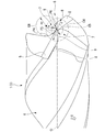
- FIG. 5 is a perspective view of the embodiment shown in FIG. 1 as viewed from the tip end side of the drill body along the thinning direction.
- FIG. 5 is a perspective view of the embodiment shown in FIG. 1 as viewed from the tip end side of the drill body along the thinning direction.
- FIG. 1 is a side view of the entire drill body showing a first modification of the embodiment shown in FIGS. 1 to 11.
- 1 is a side view of the entire drill body showing a second modification of the embodiment shown in FIGS. 1 to 11.
- the drill body 1 is integrally formed of a hard metal material such as cemented carbide in a multi-stage columnar shape centered on the axis O.
- the rear end portion of the large diameter of the drill body 1 (the left portion in FIGS. 2 and 4, 6 to 10; the upper right portion in FIG. 5) is a shank portion 2 having a columnar shape and a small diameter.
- the tip portion (the right portion in FIGS. 2 and 4, the right portion in FIGS. 6 to 10, and the lower left portion in FIG. 5) is a cutting edge portion 3.
- the shank portion 2 is gripped by the spindle of the machine tool, the drill body 1 is rotated around the axis O in the drill rotation direction T, and is sent out to the tip side in the axis O direction, and is covered by the cutting edge portion 3. Drill holes in the cutting material.
- the shank portion 2 and the cutting edge portion 3 are connected by a truncated cone-shaped tapered portion 4 centered on an axis O whose diameter gradually decreases toward the tip end side of the drill body 1.
- the tip flank surface 5 which is the tip surface of the drill body 1, is opened and twisted around the axis O toward the rear end side at a constant twist angle opposite to the drill rotation direction T.
- the chip discharge grooves 6 having a plurality of rows are formed symmetrically with respect to the axis O and extend to the front of the tapered portion 4.
- the tip flank surface 5 is a two-step tip flank surface 5 in which the clearance angle is increased by one step toward the side opposite to the drill rotation direction T.
- chip discharge grooves 6 have a concave curved shape as shown in FIG. 9 when the chip discharge groove bottom surface 6a facing the outer peripheral side of the drill body 1 is viewed from the chip discharge groove twist direction, which is the direction of the twist angle.
- the concave curve is substantially concave arc in the present embodiment.
- the twist angle of the chip discharge groove 6 is set to be in the range of 10 ° to 50 °, preferably in the range of 25 ° to 30 ° in the present embodiment.
- a concave groove-shaped thinning portion 7 is formed on the inner peripheral portion of the tip of the chip discharge groove 6 so as to cut out the bottom surface 6a of the chip discharge groove toward the inner peripheral side toward the tip side of the drill body 1.
- the thinning bottom surface 7a of the thinning portion 7 facing the outer peripheral side of the drill body 1 is viewed from the thinning direction (direction indicated by the arrow S in FIG. 8) connecting the points recessed most toward the axis O side of the thinning bottom surface 7a. It is formed so as to form a concave curve at the time, and this concave curve is also substantially concave arc in the present embodiment.
- a main cutting blade 8 having this wall surface as a rake face is formed at an intersecting ridge line portion with the tip flank surface 5 which is a tip side edge portion of the drill body 1 on the wall surface of the chip discharge groove 6 facing the drill rotation direction T. Is formed. Furthermore, the wall surface of the thinning portion 7 facing the drill rotation direction T is a thinning rake surface 7b, and the thinning rake surface 7b is formed at an intersecting ridge line portion with the tip flank surface 5 which is the tip side edge portion of the drill body 1. Is formed with a thinning blade 9 connected to the inner peripheral side of the main cutting blade 8. The main cutting blade 8 and the thinning blade 9 are provided with tip angles so as to move toward the rear end side toward the outer peripheral side of the drill body 1.
- the wall surface of the chip discharge groove 6 which is the rake face of the main cutting blade 8 and faces the drill rotation direction T is formed in a flat shape around the main cutting blade 8, whereby the main cutting blade 8 is formed. It is formed in a straight line as shown in FIG. 11 when viewed from the tip side in the O direction of the axis line.
- the thinning rake face 7b is also formed to be flat in the present embodiment, and therefore the thinning blade 9 is also formed to be linear as shown in FIG. 11 when viewed from the tip side in the O-direction of the axis, and the thinning blade 9 and the main cutting are formed.
- the blade 8 is connected to the blade 8 via a convex curved portion that is convex in the drill rotation direction T.
- the chip discharge groove bottom surface 6a has a center on the axis O when viewed from the direction in which the chip discharge groove is twisted, and the core thickness d of the cutting edge portion 3 of the drill body 1
- the contact point P1 between the first circle C1 inscribed in the chip discharge groove bottom surface 6a and the chip discharge groove bottom surface 6a having a diameter d equal to is concentric with the first circle C1.
- a second circle C2 having a diameter D2 that is 1/2 of the sum d + D of the core thickness d and the diameter D of the main cutting blade 8 (FIG. 9 shows the circle D1 of the diameter D of the main cutting blade 8).
- the radius R1 of the inscribed circle C3 of the chip discharge groove passing through the two intersections P2 and P3 with the bottom surface of the chip discharge groove is 0.3 ⁇ D2 to 0.7 with respect to the diameter D2 of the second circle C2. It is within the range of ⁇ D2.
- the thinning portion 7 has a center at the intersection of the axis O and the tip flank surface 5 when viewed from the thinning direction S, and has a diameter d equal to the core thickness d.
- the radius R2 of the thinning inscribed circle C6 passing through the two intersections P5 and P6 with 9 or the extension line of the thinning blade 9 is within the range of 0.3 ⁇ d to 0.7 ⁇ d with respect to the core thickness d. It is said that.
- the ratio A R1 / D2 of the radius R1 of the chip discharge groove inscribed circle C3 to the diameter D2 of the second circle C2, and the radius R2 of the thinning inscribed circle C6 and the core thickness d.
- the thinning direction S when viewed from a direction perpendicular to the thinning rake surface 7b, has an inclination angle ⁇ within a range of 10 ° to 55 ° with respect to the axis O.
- the drill body 1 is inclined toward the outer peripheral side toward the rear end side.
- the radius R2 of the thinning inscribed circle C6 is within the range of 0.3 ⁇ d to 0.7 ⁇ d with respect to the core thickness d when viewed from the thinning direction S. Therefore, the chips generated by the thinning blade 9 can be curled small by sliding against the thinning bottom surface 7a having a small radius of curvature along the thinning inscribed circle C6. Therefore, it is possible to prevent the chips generated by the thinning blade 9 from extending and causing clogging.
- the ratio A R1 / D2 of the radius R1 of the chip discharge groove inscribed circle C3 and the diameter D2 of the second circle C2, which is substantially equal to the radius of the chip discharge groove bottom surface 6a.
- the ratio of the curl radius of the chips to the thinning bottom surface 7a to which the chips generated by the thinning blade 9 having a small radius centered on the axis O is in sliding contact and the main cutting blade 8 having a large radius centered on the axis O can be made substantially equal.
- the chips generated by the thinning blade 9 and the main cutting blade 8 can be curled into a conical shape having a bus from the thinning direction S in the twisting direction of the chip discharge groove, and the chips generated by the thinning blade 9 can be curled.
- the flow of chips can be rectified as shown by the arrow F in FIG. 5 so as to extend in the normal direction perpendicular to the main cutting edge 8. Therefore, as described above, the chips generated by the thinning blade 9 are curled into small pieces, and the chip fragmentability can be improved. Therefore, even when drilling a deep hole with a small diameter, it is possible to prevent the drill body 1 from being broken due to chip clogging.
- the radius R1 of the inscribed circle C3 of the chip discharge groove is less than 0.3 ⁇ D2 with respect to the diameter D2 of the second circle C2, the cross-sectional area of the chip discharge groove 6 becomes smaller, and the ratio A / Even if B is in the range of 0.8 to 1.25, chip clogging may occur.
- the radius R1 of the inscribed circle C3 of the chip discharge groove exceeds 0.7 ⁇ D2 with respect to the diameter D2 of the second circle C2, the cross-sectional area of the chip discharge groove 6 becomes too large, and the drill body 1 Since the wall thickness becomes small, the strength may be impaired and breakage or the like may easily occur.
- the radius R1 of the inscribed circle C3 of the chip discharge groove is relative to the diameter D of the main cutting edge 8. It may be in the range of 0.1 ⁇ D to 0.5 ⁇ D, and the radius R2 of the thinning inscribed circle C6 is in the range of 0.3 ⁇ d to 0.7 ⁇ d with respect to the core thickness d.
- the ratio X R1 / D of the radius R1 of the inscribed circle C3 of the chip discharge groove and the diameter D of the main cutting edge 8 and the radius R2 of the inscribed circle C6 of the thinning and the center thereof.
- the radius R2 of the thinning inscribed circle C6 is less than 0.3 ⁇ d with respect to the core thickness d, the resistance when the chips generated by the thinning blade 9 are curled by the thinning bottom surface 7a may increase. There is.
- the radius R2 of the thinning inscribed circle C6 exceeds 0.7 ⁇ d with respect to the core thickness d, the chips generated by the thinning blade 9 and brought into sliding contact with the thinning bottom surface 7a are curled to a small curl diameter. There is a risk that it will not be possible to divide.
- the ratio A / B exceeds or falls below the range of 0.8 to 1.25, the ratio of the curl radius to the thinning bottom surface 7a of the chips generated by the thinning blade 9 and the axis O as the center.
- the ratio of the chips generated by the main cutting edge 8 having a large radius to the curl radius with respect to the bottom surface 6a of the chip discharge groove cannot be made substantially equal. Therefore, it becomes impossible to rectify the flow of chips so that the chips generated by the thinning blade 9 extend in the normal direction perpendicular to the main cutting blade 8, and good chip fragmentability can be obtained. It may disappear.
- the thinning direction S is 10 ° with respect to the axis O when viewed from a direction perpendicular to the thinning rake surface 7b. It is desirable that the drill body 1 is inclined toward the outer peripheral side toward the rear end side at an inclination angle ⁇ within the range of about 55 °. If the inclination angle is less than 10 ° or more than 55 °, it may be difficult to rectify the flow of chips generated by the thinning blade 9 and the main cutting blade 8 as described above.
- FIGS. 12 and 13 show first and second modified examples of the embodiments shown in FIGS. 1 to 11, and are common to the embodiments shown in FIGS. 1 to 11. Have the same code.
- the same number of coolant holes 10 as the chip discharge groove 6 are formed between the chip discharge grooves 6 in the circumferential direction from the rear end surface of the shank portion 2 of the drill body 1 to the cutting edge portion 3. It is formed so as to pass through and is open to the tip flank surface 5.
- coolant such as cutting fluid and compressed air is supplied through the coolant hole 10 and discharged to the main cutting blade 8, the thinning blade 9, and the cutting portion of the work material.
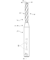
- the total length of the drill body 1 including the shank portion 2 and the cutting edge portion 3 is shorter than that of the embodiments shown in FIGS. 1 to 11, which is shown in FIG.
- the length of the chip discharge groove 6 of the cutting edge portion 3 is longer and the diameter of the shank portion 2 is smaller than that of the embodiments shown in FIGS. 1 to 11.
- the present invention is applied to a two-blade twist drill in which the main cutting blade 8 and the thinning blade 9 are two has been described.
- the number 8 and the thinning blade 9 may be one, and the present invention can be applied to three or more three-flute or more twist drills.
- the chips generated by the thinning blade can be curled into small pieces, and the chips flow so as to extend in the normal direction perpendicular to the main cutting blade like the chips generated by the main cutting blade. Can be rectified. Therefore, it is possible to improve the separability of the chips generated by the thinning blade and the main cutting blade, and prevent the drill body from being broken due to chip clogging even in deep hole drilling with a small diameter.
- Drill body 2 Shank part 3 Cutting edge part 4 Tapered part 5 Tip relief surface 6 Chip discharge groove 6a Chip discharge groove bottom surface 7 Thinning part 7a Thinning bottom surface 7b Thinning rake surface 8 Main cutting edge 9 Thinning blade 10 Coolant hole O Drill body 1 Axis T Drill rotation direction D Diameter of main cutting edge 8 C Center thickness circle d Center thickness C1 First circle C2 Second circle C3 Chip discharge groove inscribed circle C4 Third circle C5 Fourth circle C6 Inside thinning Inscribed circle D1 Chip discharge groove A circle concentric with the first circle C1 and having a diameter D of the main cutting edge 8 when viewed from the twisting direction D2 The diameter of the second circle (core thickness d and the diameter D of the main cutting edge 8) (1 1/2 diameter of sum d + D) P1 Contact point between the first circle C1 and the bottom surface 6a of the chip discharge groove when viewed from the twisting direction of the chip discharge groove P2, P3 Intersection point between the second circle C2 and the bottom surface 6a of the chip discharge groove P4 When
Landscapes
- Engineering & Computer Science (AREA)
- Mechanical Engineering (AREA)
- Drilling Tools (AREA)
Priority Applications (3)
| Application Number | Priority Date | Filing Date | Title |
|---|---|---|---|
| CN202080044001.XA CN113993644B (zh) | 2019-07-08 | 2020-06-30 | 钻头 |
| EP20836007.3A EP3998131A4 (en) | 2019-07-08 | 2020-06-30 | DRILL |
| US17/625,170 US20220266352A1 (en) | 2019-07-08 | 2020-06-30 | Drill |
Applications Claiming Priority (2)
| Application Number | Priority Date | Filing Date | Title |
|---|---|---|---|
| JP2019-127145 | 2019-07-08 | ||
| JP2019127145 | 2019-07-08 |
Publications (1)
| Publication Number | Publication Date |
|---|---|
| WO2021006115A1 true WO2021006115A1 (ja) | 2021-01-14 |
Family
ID=74115238
Family Applications (1)
| Application Number | Title | Priority Date | Filing Date |
|---|---|---|---|
| PCT/JP2020/025667 WO2021006115A1 (ja) | 2019-07-08 | 2020-06-30 | ドリル |
Country Status (5)
| Country | Link |
|---|---|
| US (1) | US20220266352A1 (zh) |
| EP (1) | EP3998131A4 (zh) |
| JP (1) | JP7447707B2 (zh) |
| CN (1) | CN113993644B (zh) |
| WO (1) | WO2021006115A1 (zh) |
Families Citing this family (1)
| Publication number | Priority date | Publication date | Assignee | Title |
|---|---|---|---|---|
| JP7095832B1 (ja) * | 2021-03-23 | 2022-07-05 | 住友電工ハードメタル株式会社 | ドリルヘッド、先端交換式ドリル及びドリル |
Citations (7)
| Publication number | Priority date | Publication date | Assignee | Title |
|---|---|---|---|---|
| JPS618264B2 (zh) | 1984-07-23 | 1986-03-13 | Mitsubishi Electric Corp | |
| JPS6268213A (ja) * | 1986-09-26 | 1987-03-28 | Kobe Steel Ltd | ドリル |
| JP2006281407A (ja) * | 2005-04-04 | 2006-10-19 | Osg Corp | 非鉄金属加工用ドリル |
| WO2009054400A1 (ja) * | 2007-10-26 | 2009-04-30 | Sumitomo Electric Hardmetal Corp. | ツイストドリル |
| US20110170973A1 (en) * | 2008-05-16 | 2011-07-14 | Guehring Ohg | Multi-blade solid carbide drill |
| WO2015025872A1 (ja) * | 2013-08-22 | 2015-02-26 | 三菱マテリアル株式会社 | ドリル |
| JP2019127145A (ja) | 2018-01-24 | 2019-08-01 | トヨタ自動車株式会社 | 車両用ドア開閉構造 |
Family Cites Families (6)
| Publication number | Priority date | Publication date | Assignee | Title |
|---|---|---|---|---|
| JP3515167B2 (ja) * | 1994-05-13 | 2004-04-05 | 三菱マテリアル株式会社 | ドリル |
| JP2003300111A (ja) | 2002-04-10 | 2003-10-21 | Hitachi Tool Engineering Ltd | ツイストドリル |
| WO2008001412A1 (fr) * | 2006-06-23 | 2008-01-03 | Osg Corporation | Foret |
| JPWO2012070640A1 (ja) | 2010-11-26 | 2014-05-19 | 株式会社タンガロイ | 小径ドリル |
| EP3015203B1 (en) * | 2013-06-26 | 2020-09-09 | Kyocera Corporation | Drill |
| EP3444059B1 (en) * | 2016-04-15 | 2022-08-17 | MOLDINO Tool Engineering, Ltd. | Small-diameter drill bit |
-
2020
- 2020-06-30 JP JP2020113318A patent/JP7447707B2/ja active Active
- 2020-06-30 EP EP20836007.3A patent/EP3998131A4/en active Pending
- 2020-06-30 US US17/625,170 patent/US20220266352A1/en active Pending
- 2020-06-30 CN CN202080044001.XA patent/CN113993644B/zh active Active
- 2020-06-30 WO PCT/JP2020/025667 patent/WO2021006115A1/ja unknown
Patent Citations (7)
| Publication number | Priority date | Publication date | Assignee | Title |
|---|---|---|---|---|
| JPS618264B2 (zh) | 1984-07-23 | 1986-03-13 | Mitsubishi Electric Corp | |
| JPS6268213A (ja) * | 1986-09-26 | 1987-03-28 | Kobe Steel Ltd | ドリル |
| JP2006281407A (ja) * | 2005-04-04 | 2006-10-19 | Osg Corp | 非鉄金属加工用ドリル |
| WO2009054400A1 (ja) * | 2007-10-26 | 2009-04-30 | Sumitomo Electric Hardmetal Corp. | ツイストドリル |
| US20110170973A1 (en) * | 2008-05-16 | 2011-07-14 | Guehring Ohg | Multi-blade solid carbide drill |
| WO2015025872A1 (ja) * | 2013-08-22 | 2015-02-26 | 三菱マテリアル株式会社 | ドリル |
| JP2019127145A (ja) | 2018-01-24 | 2019-08-01 | トヨタ自動車株式会社 | 車両用ドア開閉構造 |
Non-Patent Citations (1)
| Title |
|---|
| See also references of EP3998131A4 |
Also Published As
| Publication number | Publication date |
|---|---|
| CN113993644A (zh) | 2022-01-28 |
| US20220266352A1 (en) | 2022-08-25 |
| JP7447707B2 (ja) | 2024-03-12 |
| EP3998131A4 (en) | 2023-08-02 |
| EP3998131A1 (en) | 2022-05-18 |
| CN113993644B (zh) | 2024-02-27 |
| JP2021011013A (ja) | 2021-02-04 |
Similar Documents
| Publication | Publication Date | Title |
|---|---|---|
| US4744705A (en) | Twist drill bit | |
| JP5739498B2 (ja) | ドリル工具用ビット | |
| EP2233234B1 (en) | End mill | |
| EP3342514B1 (en) | Drill | |
| JP4704495B2 (ja) | タービン翼接続用溝の切削加工方法およびそれに用いるクリスマスカッタ | |
| KR102492629B1 (ko) | 드릴 | |
| JP2007136627A (ja) | エンドミル | |
| JP2008137125A (ja) | ドリル | |
| WO2019044791A1 (ja) | テーパーリーマ | |
| WO2021006115A1 (ja) | ドリル | |
| JP5286928B2 (ja) | エンドミル | |
| WO2020213482A1 (ja) | ドリル | |
| JP7206496B2 (ja) | ドリル | |
| JP2021088007A (ja) | ドリル | |
| JP6994166B1 (ja) | 切削工具 | |
| JP2002126925A (ja) | ツイストドリル | |
| JP2022016103A (ja) | ボールエンドミル | |
| WO2012053090A1 (ja) | 3枚刃ドリル | |
| JP6902284B2 (ja) | 切削工具 | |
| JP2005177891A (ja) | ドリル | |
| JP7409244B2 (ja) | ボールエンドミル | |
| WO2023132056A1 (ja) | ボールエンドミル | |
| JP4608933B2 (ja) | ドリル、スローアウェイ式ドリル及びスローアウェイチップ | |
| WO2022201298A1 (ja) | ドリルヘッド、先端交換式ドリル及びドリル | |
| JP2022016104A (ja) | ボールエンドミル |
Legal Events
| Date | Code | Title | Description |
|---|---|---|---|
| 121 | Ep: the epo has been informed by wipo that ep was designated in this application |
Ref document number: 20836007 Country of ref document: EP Kind code of ref document: A1 |
|
| ENP | Entry into the national phase |
Ref document number: 2020836007 Country of ref document: EP Effective date: 20220208 |