WO2021005778A1 - 圧延装置の制御装置及び圧延設備並びに圧延装置の運転方法 - Google Patents
圧延装置の制御装置及び圧延設備並びに圧延装置の運転方法 Download PDFInfo
- Publication number
- WO2021005778A1 WO2021005778A1 PCT/JP2019/027491 JP2019027491W WO2021005778A1 WO 2021005778 A1 WO2021005778 A1 WO 2021005778A1 JP 2019027491 W JP2019027491 W JP 2019027491W WO 2021005778 A1 WO2021005778 A1 WO 2021005778A1
- Authority
- WO
- WIPO (PCT)
- Prior art keywords
- rolling
- plate
- metal plate
- pair
- tip
- Prior art date
- Legal status (The legal status is an assumption and is not a legal conclusion. Google has not performed a legal analysis and makes no representation as to the accuracy of the status listed.)
- Ceased
Links
Images








Classifications
-
- B—PERFORMING OPERATIONS; TRANSPORTING
- B21—MECHANICAL METAL-WORKING WITHOUT ESSENTIALLY REMOVING MATERIAL; PUNCHING METAL
- B21B—ROLLING OF METAL
- B21B37/00—Control devices or methods specially adapted for metal-rolling mills or the work produced thereby
-
- B—PERFORMING OPERATIONS; TRANSPORTING
- B21—MECHANICAL METAL-WORKING WITHOUT ESSENTIALLY REMOVING MATERIAL; PUNCHING METAL
- B21B—ROLLING OF METAL
- B21B15/00—Arrangements for performing additional metal-working operations specially combined with or arranged in, or specially adapted for use in connection with, metal-rolling mills
- B21B2015/0057—Coiling the rolled product
-
- B—PERFORMING OPERATIONS; TRANSPORTING
- B21—MECHANICAL METAL-WORKING WITHOUT ESSENTIALLY REMOVING MATERIAL; PUNCHING METAL
- B21B—ROLLING OF METAL
- B21B2265/00—Forming parameters
- B21B2265/02—Tension
- B21B2265/08—Back or outlet tension
-
- B—PERFORMING OPERATIONS; TRANSPORTING
- B21—MECHANICAL METAL-WORKING WITHOUT ESSENTIALLY REMOVING MATERIAL; PUNCHING METAL
- B21B—ROLLING OF METAL
- B21B2273/00—Path parameters
- B21B2273/04—Lateral deviation, meandering, camber of product
-
- B—PERFORMING OPERATIONS; TRANSPORTING
- B21—MECHANICAL METAL-WORKING WITHOUT ESSENTIALLY REMOVING MATERIAL; PUNCHING METAL
- B21B—ROLLING OF METAL
- B21B2273/00—Path parameters
- B21B2273/06—Threading
- B21B2273/10—Threading-out or after threading-out
-
- B—PERFORMING OPERATIONS; TRANSPORTING
- B21—MECHANICAL METAL-WORKING WITHOUT ESSENTIALLY REMOVING MATERIAL; PUNCHING METAL
- B21B—ROLLING OF METAL
- B21B2273/00—Path parameters
- B21B2273/12—End of product
- B21B2273/14—Front end or leading end
-
- B—PERFORMING OPERATIONS; TRANSPORTING
- B21—MECHANICAL METAL-WORKING WITHOUT ESSENTIALLY REMOVING MATERIAL; PUNCHING METAL
- B21B—ROLLING OF METAL
- B21B37/00—Control devices or methods specially adapted for metal-rolling mills or the work produced thereby
- B21B37/48—Tension control; Compression control
-
- B—PERFORMING OPERATIONS; TRANSPORTING
- B21—MECHANICAL METAL-WORKING WITHOUT ESSENTIALLY REMOVING MATERIAL; PUNCHING METAL
- B21B—ROLLING OF METAL
- B21B37/00—Control devices or methods specially adapted for metal-rolling mills or the work produced thereby
- B21B37/68—Camber or steering control for strip, sheets or plates, e.g. preventing meandering
-
- B—PERFORMING OPERATIONS; TRANSPORTING
- B21—MECHANICAL METAL-WORKING WITHOUT ESSENTIALLY REMOVING MATERIAL; PUNCHING METAL
- B21B—ROLLING OF METAL
- B21B38/00—Methods or devices for measuring, detecting or monitoring specially adapted for metal-rolling mills, e.g. position detection, inspection of the product
Definitions
- the present disclosure relates to a control device for a rolling apparatus, a rolling apparatus, and an operation method for the rolling apparatus.
- the metal plate In the rolling of a metal plate using a rolling mill containing a pair of rolling rolls, the metal plate is rolled in a state where the tension on the exit side of the rolling mill does not act on the metal plate before the tip of the metal plate is wound by the winder. Rolling (tip non-tensile rolling) may be performed.
- Patent Document 1 uses a rolling apparatus including a rolling mill (rolling roll) and a tension reel (winding machine) provided on the outlet side of the rolling mill, and tensions the rolled material (metal plate). It is stated that rolling is performed before it is wound on a reel and the tension on the exit side of the rolling mill is established. Further, in Patent Document 1, a meandering detector is provided on the outlet side of the rolling mill on the upstream side of the tension reel, and the offset amount detected by the meandering detector (the axial center position of the rolling roll and the plate of the rolled material). It is described that the leveling control of the rolling mill is performed based on the difference from the center position in the width direction). As a result, it is possible to improve the yield by suppressing meandering and one-sided elongation of the rolled material that may occur when rolling in the absence of tension on the exit side.
- a meandering detector is provided on the outlet side of the rolling mill on the upstream side of the tension reel, and the offset amount detected by the meandering detector
- the plate width of the metal plate is widened by using the position sensor (serpentine detector in Patent Document 1) provided on the outlet side of the rolling roll in the state of no tension at the tip where the extension side tension does not act on the metal plate. It is possible to detect the position of a predetermined portion in the direction (center position or plate edge position) and control the rolling mill based on the detected value. However, even if the position of the predetermined portion of the metal plate to be detected in the plate width direction deviates from the specified position at the position of the rolling mill (for example, the center position of the metal plate in the plate width direction is the axial center of the rolling roll).
- the position detected by the position sensor may match the above-mentioned specified position. obtain. In this case, it is not possible to properly grasp that the outflow direction of the metal plate is tilted from the detection result by the position sensor. Therefore, if rolling is continued in this state, the tip of the metal plate may be separated from the transfer line by the rolling mill in the plate width direction, and the rolled metal plate may not be properly wound by the winding device. is there.
- At least one embodiment of the present invention includes a control device and rolling equipment of a rolling apparatus capable of appropriately winding a metal plate rolled in a state of no tension at the tip by a winding apparatus, and rolling.
- the purpose is to provide a method of operating the device.
- the control device for the rolling mill is A control device for controlling a rolling apparatus including a pair of rolling rolls provided so as to sandwich a metal plate.
- a first plate provided on the entry side of the pair of rolling rolls in the transport direction of the metal plate and configured to detect a plate end position in the plate width direction of the metal plate at the first position in the transport direction.
- Edge detector and A second plate edge detection unit provided on the exit side of the pair of rolling rolls in the transport direction and configured to detect the plate end position of the metal plate in the plate width direction at the second position in the transport direction.
- the said A determination unit configured to determine whether or not tip non-tension rolling, which is the rolling of the metal plate by the pair of rolling rolls, can be started in a state where the output tension of the metal plate is zero. To be equipped.
- a control device for a rolling apparatus, a rolling apparatus, and an operating method for the rolling apparatus capable of appropriately winding a metal plate rolled in a state of no tension at the tip with a winding apparatus.
- the rolling equipment 1 includes a rolling apparatus 2 and a control device 100 for controlling the rolling apparatus 2.
- the rolling mill 2 may include, for example, one rolling mill 10 as shown in FIG. 1, for example, two rolling mills 10 (10A, 10B) as shown in FIG. May include, or may include three or more rolling mills 10.
- the rolling apparatus 2 shown in FIG. 1 is a rolling apparatus (reverse mill) that reciprocates and rolls a metal plate 90 passed between a pair of rolling rolls 15 and 16.
- the rolling apparatus 2 shown in FIG. 1 includes a rolling mill 10 including a pair of rolling rolls (work rolls) 15 and 16 provided so as to sandwich a metal plate 90 which is a rolling material, and a rolling roll in the traveling direction of the metal plate 90.
- a pair of rolling devices 90 is included, including a winding device 4 provided on the inlet side of the 15 and 16 and a winding device 14 provided on the outlet side of the rolling rolls 15 and 16 in the traveling direction of the metal plate 90. It is configured to be rolled by rolls 15 and 16.
- the rolling apparatus 2 shown in FIG. 2 is a rolling apparatus (reverse mill) for reciprocating and rolling a metal plate 90 between a pair of first rolling rolls 15A and 16A and a pair of second rolling rolls 15B and 16B. Is.
- the rolling apparatus 2 shown in FIG. 2 sandwiches the metal plate 90 with the first rolling mill 10A including a pair of first rolling rolls (work rolls) 15A and 16A provided so as to sandwich the metal plate 90 which is a rolling material.
- the second rolling mill 10B including the pair of second rolling rolls (work rolls) 15B and 16B provided in the above, and the unwinding device 4 provided on the inlet side of the first rolling rolls 15A and 16A in the traveling direction of the metal plate 90.
- a take-up device 14 provided on the outlet side of the second rolling rolls 15B and 16B in the traveling direction of the metal plate 90, and the metal plate 90 is combined with the pair of first rolling rolls 15A and 16A and the pair of second rolling rolls 15A and 16A. It is configured to be rolled by rolling rolls 15B and 16B.
- the illustrated rolling mills 10, 10A and 10B have the same configuration.
- the configuration of the rolling mill 10 will be described below, but the same description applies to the rolling mills 10A and 10B.
- FIG. 2 as the codes of the components (rolling rolls, etc.) of the rolling mills 10A and 10B, the components of the rolling mill 10 shown in FIG. 1 are similarly coded with "A" or "B", respectively. Have been described.
- the pair of intermediate rolls 17 and 18 provided on the opposite sides of the metal plate 90 with the pair of rolling rolls 15 and 16 sandwiched therein, and Includes a pair of backup rolls 19, 20 and.
- the intermediate rolls 17 and 18 and the backup rolls 19 and 20 are configured to support the rolling rolls 15 and 16.
- the rolling mill 10 is provided with a rolling device 22 for applying a load to the pair of rolling rolls 15 and 16 to reduce the metal plate 90 sandwiched between the pair of rolling rolls 15 and 16.
- the reduction device 22 may include a hydraulic cylinder.
- a motor (not shown) is connected to the rolling rolls 15 and 16 via a spindle (not shown) or the like, and the rolling rolls 5 and 16 are rotationally driven by the motor.
- the rolling rolls 15 and 16 are rotated by a motor while the metal plate 90 is rolled by the rolling device 22, so that a frictional force is generated between the rolling rolls 15 and 16 and the metal plate 90.
- the frictional force causes the metal plate 90 to be sent to the exit side of the rolling rolls 15 and 16.
- the unwinding device 4 is configured to unwind the metal plate 90 toward the rolling mill 10.
- the take-up device 14 is configured to take up the metal plate 90 from the rolling mill 10.
- the unwinding device 4 and the winding device 14 are each driven by a motor (not shown).
- the unwinding device 4 is configured to give an entry side tension to the metal plate 90 when the metal plate 90 is rolled. Further, the winding device 14 is configured to apply an exit tension to the metal plate 90 when the metal plate 90 is rolled. That is, by appropriately driving the unwinding device 4 and the winding device 14 by the motor, the metal plate 90 is given the entry side tension and the exit side tension. By appropriately applying the entry-side tension and the exit-side tension to the metal plate 90, meandering of the metal plate 90 during rolling can be suppressed.
- the rolling apparatus 2 shown in FIGS. 1 and 2 includes an entry side pinch roll 6 and a side guide 8 for guiding the metal plate 90 introduced into the rolling mill 10 from the unwinding apparatus 4, and a winding apparatus from the rolling mill 10. Further includes an outlet pinch roll 12 for guiding the metal plate 90 sent to 14.
- the control device 100 for controlling the rolling apparatus 2 is a first plate edge detecting unit 32 and a second plate for detecting the plate end position of the metal plate 90 in the plate width direction. It includes an edge detection unit 34 and a controller 40 configured to control the operation of the rolling apparatus 2 based on the detection results of the first plate end detection unit 32 and the second plate end detection unit 34.
- the first plate edge detection unit 32 is provided on the entry side of the pair of rolling rolls 15 and 16 in the transport direction of the metal plate 90, and is located at the plate end position in the plate width direction of the metal plate at the first position Y1 in the transport direction. It is configured to detect a certain first plate end position x1.
- the second plate edge detecting unit 34 is provided on the exit side of the pair of rolling rolls 15 and 16 in the conveying direction, and is the second plate which is the plate end position in the plate width direction of the metal plate at the second position Y2 in the conveying direction. It is configured to detect the end position x2.
- the control device 100 shown in FIG. 2 is provided with first plate end detection units 32A and 32B on the entry side in the transport direction with respect to the first rolling rolls 15A and 16A and the second rolling rolls 15B and 16B, respectively.
- Second plate edge detection units 34A and 34B are provided on the exit side in the transport direction.
- the controller 40 receives signals indicating measurement results from the first plate edge detection unit 32 and the second plate edge detection unit 34, and drives the rolling device 22 and the rolling rolls 15 and 16 based on these measurement results. It is configured to control the operation of the motor.
- the controller 40 may include a CPU, a memory (RAM), an auxiliary storage unit, an interface, and the like.
- the controller 40 receives signals from the first plate edge detection unit 32 and the second plate edge detection unit 34 via the interface.
- the CPU is configured to process the signal received in this way. Further, the CPU is configured to process a program expanded in the memory.
- the processing content of the controller 40 may be implemented as a program executed by the CPU and stored in the auxiliary storage unit. When the programs are executed, these programs are expanded in memory. The CPU reads the program from the memory and executes the instructions included in the program.
- FIG. 3 is a schematic configuration diagram of a controller 40 constituting the control device 100 according to the embodiment.
- the controller 40 includes a determination unit 42 and a rolling control unit 44.
- the determination unit 42 includes the first plate end position x1 of the metal plate 90 detected by the first plate end detection unit 32 and the second plate end of the metal plate 90 detected by the second plate end detection unit 34. Based on the position x2, it is configured to determine whether or not the rolling of the metal plate 90 (tip non-tensile rolling) can be started by the pair of rolling rolls 15 and 16 in the state where the output tension of the metal plate 90 is zero. ..
- the rolling control unit 44 is configured to control the operation of the pair of rolling rolls 15 and 16.
- the rolling control unit 44 is configured to control a motor for driving the rolling device 22 and the rolling rolls 15 and 16 in order to adjust the gap between the rolls of the rolling rolls 15 and 16 and the rotation speed. To. Each part of the controller 40 other than the determination part 42 will be described later.
- the control device 100 may further have a display unit (display or the like; not shown) for displaying the determination result by the determination unit 42.
- a display unit display or the like; not shown
- the rolling apparatus 2 may be operated by manually performing a part or all of the processing by the control device 100 described below.
- FIG. 4 is a flowchart showing an example of an operation method of the rolling apparatus 2 according to the embodiment. Note that FIG. 4 is a flowchart showing an example of an operation method until the tip tensionless rolling of the metal plate 90 is started. The operation method after starting the tip tensionless rolling of the metal plate 90 will be described later with reference to the flowcharts of FIGS. 11 and 14.
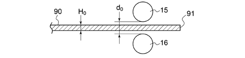
- 5A to 5C are schematic views showing the states of the rolling rolls 15 and 16 and the metal plate 90 when the tip tensionless rolling of the metal plate 90 is started, respectively.
- 6 and 7 are diagrams for explaining the determination of whether or not the tip tensionless rolling can be started by the determination unit 42, respectively.
- the controller 40 makes a pair of rolling rolls 15 and 16 so that the gap (gap between rolls) is larger than the thickness of the metal plate 90.
- the positions of the rolling rolls 15 and 16 are adjusted (step S102).
- the position of the pair of rolling rolls 15 and 16 may be adjusted by operating the rolling device 22 as needed.
- the tip portion (see FIG. 5A) including the tip 91 of the metal plate 90 is passed between the pair of rolling rolls 15 and 16 while maintaining the state where the gap between the rolls is larger than the plate thickness (step S104).
- FIG. 5A is a schematic view showing the states of the rolling rolls 15 and 16 and the metal plate 90 when step S104 is completed.
- the tip 91 of the metal plate 90 is held in a state where the gap d0 between the pair of rolling rolls 15 and 16 is larger than the plate thickness H0 of the metal plate 90 before rolling.
- the tip including the tip is passed between the rolling rolls 15 and 16.
- the tip portion including the tip 91 of the metal plate 90 is located on the exit side of the rolling rolls 15 and 16, and does not reach the winding device 14. Therefore, the output tension Td acting on the metal plate 90 is zero. Further, at this point, since the entry side tension Te is not applied to the metal plate 90, the entry side tension Te is also zero.
- the first plate end detection unit 32 is used to detect the first plate end position x1 at the first position Y1 in the transport direction
- the second plate end detection unit 34 is used to detect the second position in the transport direction.
- the second plate end position x2 in Y2 is detected (step S106).
- FIGS. 6 and 7 are schematic views of the rolling rolls 15 and 16 and the metal plate 90 before the start of rolling, respectively.
- the metal plate 90 has a plate width W, and has a first end edge 92 and a second end edge 93 which are both end edges in the plate width direction.
- the first plate end detection unit 32 and the second plate end detection unit 34 have a first plate end position x1 and a second plate end position x2, respectively, as a first position Y1 and a second position Y2. It may be configured to detect the position of the first edge 92 in (see FIGS. 6 and 7).
- the first plate end detection unit 32 and the second plate end detection unit 34 are set to the first plate end position x1 and the second plate end position x2, respectively, as the first position Y1 and the second position. It may be configured to detect the position of the second edge 93 in Y2.
- step S106 the determination unit 42 determines whether or not the tip tensionless rolling of the metal plate 90 can be started based on the first plate end position x1 and the second plate end position x2 detected in step S106. (Step S108).
- step S108 for example, when the longitudinal direction of the metal plate 90 is substantially parallel to the conveying direction of the metal plate 90 by the rolling apparatus 2 (see FIG. 6), it is determined that the tip tensionless rolling of the metal plate 90 can be started. However, when the inclination of the metal plate 90 in the longitudinal direction with respect to the transport direction of the metal plate 90 is equal to or more than a specified degree (see FIG. 7), it is determined that the tip untensile rolling of the metal plate 90 cannot be started.
- step S108 when the difference
- step S108 the difference (x1-x ref ) between the reference position x ref and the first plate end position x1 in the plate width direction of the metal plate 90, and the reference position x ref and the second plate.
- the difference (x2-x ref ) from the end position x2 is equal to or less than the threshold x th2 , it is determined that the tip untensile rolling of the metal plate 90 can be started, and the above difference (x1-x ref ) or (x1-x ref ) or ( When at least one of x2-x ref ) is larger than the threshold value x th2, it is determined that the tip untensile rolling of the metal plate 90 cannot be started.
- the above-mentioned reference position x ref is the plate width direction (that is, the rolling rolls 15 and 16) when the longitudinal direction of the metal plate 90 coincides with the transport direction by the rolling rolls 15 and 16 (rolling machine). It is a specified position in the axial direction (direction of the central axis O).
- the above-mentioned reference position x ref may be, for example, the central position in the axial direction of the rolling rolls 15 and 16 (see FIGS. 6 and 7). In FIG.
- the longitudinal direction of the metal plate 90 coincides with the transport direction by the rolling roll, and at this time, the position of the center line Lc along the longitudinal direction of the metal plate 90 is the above-mentioned plate width direction ( That is, it coincides with the reference position x ref in the axial direction of the rolling rolls 15 and 16).
- step S108 If it is determined in step S108 above that it is not possible to start the tip tensionless rolling of the metal plate 90 (No in step S108), the position of the metal plate 90 in the plate width direction is corrected (step S110), and the step again.
- step S106 detection of the first plate end position x1 and the second plate end position x2 (step S106), and determination of whether or not to start the tip tensionless rolling of the metal plate 90 based on the detection result in step S106 (step). S108) is performed.
- step S108 when it is determined in step S108 that the tip tensionless rolling of the metal plate 90 can be started (Yes in step S108), the rolling control unit 44 starts the tip tensionless rolling of the metal plate 90 (Yes). Step S112).
- step S112 the metal plate 90 is pressed by the pair of rolling rolls 15 and 16 in a state where the output tension Td applied to the metal plate 90 is zero, and the rotation of the pair of rolling rolls 15 and 16 is started to start the rotation of the metal.
- the tipless tension rolling of the plate 90 is started (see FIG. 5B).
- the rolling down device 22 When rolling down the metal plate 90 with a pair of rolling rolls 15 and 16, as shown in FIG. 5B, the rolling down device 22 is operated so that the gap between the rolls becomes a value d1 corresponding to the target plate thickness.
- the gap d1 between rolls at this point is smaller than the plate thickness H0 of the metal plate 90 before rolling.
- the rotation speed of the rolling rolls 15 and 16 is adjusted to an appropriate value by adjusting the current value of the motor for driving the rolling rolls 15 and 16. ..
- the metal plate 90 advances in the direction of the arrow shown in FIG. 5B. Then, as shown in FIG. 5C, in the metal plate 90 after the start of rolling, the portion of the metal plate 90 that is pressed by the rolling rolls 15 and 16 and advances to the exit side of the rolling rolls 15 and 16 is thicker than the plate thickness H0 before rolling. It has a thin plate thickness H1.
- the tip of the metal plate 90 is compared with the case where the tip of the metal plate is wound around a winding device and rolling is started in a state where the outward tension is applied. Rolling can be started from a portion close to, and the yield of the metal plate 90 can be improved.
- step S108 After it was determined in step S108 that the tip tensionless rolling of the metal plate 90 was possible, the tip tensionless rolling was started by starting the tip tensionless rolling in step S112.
- the metal plate 90 can be appropriately wound by the winding device 14.
- the plate end position detection unit is provided only at one location on the exit side of the rolling rolls 15 and 16, the following problems may occur. That is, for example, as shown in FIG. 7, even if the longitudinal direction of the metal plate 90 is inclined with respect to the transport direction of the metal plate 90 by the rolling rolls 15 and 16 (rolling machine 10) before the start of rolling, the transfer is performed. From the plate end position detection result at only one point in the direction, it is unclear whether the longitudinal direction of the metal plate 90 is inclined with respect to the above-mentioned transport direction. In this case, when the tip tensionless rolling is started, the outflow direction of the metal plate 90 from the rolling rolls 15 and 16 remains inclined with respect to the transport direction by the rolling mill 10.
- the plate end position (for example, the second plate end position x2 in FIG. 7) detected by the plate end position detecting unit arranged on the exit side is substantially constant even after the start of rolling. Therefore, even if the control is performed based on the detected plate edge position, the inclination of the metal plate 90 with respect to the transport direction cannot be corrected, and if rolling is continued in this state, the tip of the metal plate 90 becomes the rolling mill 10. In some cases, the metal plate 90 after rolling cannot be properly wound by the winding device 14 because the metal plate 90 is separated from the conveying line in the plate width direction.
- step S106 in each of the first position Y1 on the entry side and the second position Y2 on the exit side of the pair of rolling rolls 15 and 16, the plate width direction of the metal plate 90
- the plate edge position (first plate edge position x1 and second plate edge position x2) is detected. Therefore, based on these detection results, it is possible to grasp the degree of inclination of the metal plate 90 with respect to the transport direction in the longitudinal direction before the start of the tip tensionless rolling, that is, the metal plate at the start of the tip tensionless rolling. It is possible to grasp the degree of inclination of 90 with respect to the transport direction in the outflow direction.
- step S108 it is determined whether or not the tip tensionless rolling can be started based on the detection results of the first plate end position x1 and the second plate end position x2. Therefore, for example, based on the above detection result.
- the tipless tension rolling of the metal plate 90 can be started. Can be determined.
- the tip tensionless rolling can be started in a state where the outflow direction and the transport direction of the metal plate 90 are substantially parallel, so that the tip portion of the metal plate 90 is a plate from the transport line by the rolling mill 10. It is possible to suppress the deviation in the width direction. Therefore, the rolled metal plate 90 can be easily wound appropriately by the winding device 14.
- the tip tensionless rolling can be started in a state where the outflow direction and the transport direction of the metal plate 90 are substantially parallel, the second plate end position x2 acquired at the start of the tip tensionless rolling.
- rolling leveling control of the rolling mill 10 such as meandering control of the metal plate 90 based on the position of the second plate end detected during tip tensionless rolling.
- the control device 100 is a pair of first rolling rolls 15A and 16A (first). It was determined whether or not the first tip tensionless rolling of the metal plate 90 in the rolling mill 10A) could be started, and it was determined that the first tip tensionless rolling could be started, and the pair of first rolling rolls 15A, After the tip tensionless rolling by 16A is started, it is configured to determine whether or not the second tip tensionless rolling of the metal plate 90 in the pair of second rolling rolls 15B and 16B can be started.
- the above-mentioned steps S102 to S112 are performed on the first rolling mill 10A, and when the tip tensionless rolling of the metal plate 90 is started, then the above-mentioned steps S102 to S112 are performed on the second rolling mill 10B. ..
- the tip tension is not applied in step S108. It was determined whether or not rolling could be started, and based on this determination result, tip tensionless rolling was started in step S112. Therefore, the metal plate 90 tip tensionless rolled by these rolling rolls 15 and 16.
- the rolling rolls 15A and 16A and the pair of rolling rolls 15B and 16B can be used for more efficient rolling while enabling the winding device to appropriately wind the rolling rolls.
- the first plate edge detection unit 32 and the second plate edge detection unit 34 are provided as close as possible to the rolling rolls 15 and 16 in the transport direction of the metal plate 90 by the rolling rolls 15 and 16.
- the first plate end detection unit 32 and the second plate end detection unit 34 use the first plate end position x1 and the second plate end position. x2 can be detected, and based on this detection result, rolling can be started with the tip 91 of the metal plate 90 placed near the rolling rolls 15 and 16, and the yield of the metal plate 90 is effective. This is because it can be improved.
- the pair of rolling rolls 15 and 16 and the winding device 14 in the transport direction is L2 (see FIGS. 1 and 2)
- the pair of rolling rolls 15 and 16 and the second plate The distance Lb (see FIGS. 1 and 2) with the end detection unit 34 in the transport direction is 0.1 ⁇ L2 or less. In some embodiments, the distance Lb described above is 0.5 ⁇ L2 or less.
- the distance between the pair of rolling rolls 15 and 16 and the winding device 14 in the transport direction is the distance between the central axis O of the pair of rolling rolls 15 and 16 and the central axis of the winding device 14 in the transport direction.
- the distance between the pair of rolling rolls 15 and 16 and the second plate end detection unit 34 in the transport direction is the central axis of the pair of rolling rolls 15 and 16 and the center position of the second plate end detection unit 34, or , The distance in the transport direction from the plate edge detection position (second position Y2) by the second plate edge detection unit 34.
- the direction of the central axis O of the rolling rolls 15 and 16, the direction of the central axis of the unwinding device 4, and the direction of the central axis of the winding device 14 are substantially parallel to each other.
- the tip 91 of the metal plate 90 at the start of non-tension rolling is rolled. Although it is relatively close, it is possible to detect the second plate end position x2 at the start of non-tensile rolling and during non-tensile rolling. Therefore, the tip non-tension rolling can be appropriately performed while shortening the length of the unrolled tip portion of the metal plate 90, whereby the yield of the metal plate 90 can be effectively improved.
- the pair of rolling rolls 15 and 16 and the first plate when the distance between the pair of rolling rolls 15 and 16 and the unwinding device 4 in the transport direction is L1 (see FIGS. 1 and 2), the pair of rolling rolls 15 and 16 and the first plate
- the distance La in the transport direction with the end detection unit 32 is 0.1 ⁇ L1 or less. In some embodiments, the distance La described above is 0.5 x L1 or less.
- the distance L1 in the transport direction between the pair of rolling rolls 15 and 16 and the unwinding device 4 is the distance L1 in the transport direction between the central axis O of the pair of rolling rolls 15 and 16 and the central axis of the unwinding device 4.
- the distance between the pair of rolling rolls 15 and 16 and the first plate end detection unit 32 in the transport direction is the central axis O of the pair of rolling rolls 15 and 16 and the center position of the first plate end detection unit 32.
- it is the distance in the transport direction from the plate edge detection position (first position Y1) by the first plate edge detection unit 32.
- the transport direction of the metal plate 90 is reversed in the second pass after the first pass is completed.
- Rolling on the rolling rolls 15 and 16 is started from the rear end side of the metal plate 90.
- the distances between the first plate edge detection unit 32 and the rolling rolls 15 and 16 are compared in the transport direction in the second pass (opposite to the transport direction in the first pass).
- the rear end position of the metal plate 90 at the start of the second pass of non-tensile rolling was set relatively close to the rolling roll, and the first plate end position x1 was set at the start of non-tension rolling and during non-tension rolling. Can be detected. Therefore, the tip tensionless rolling can be appropriately performed while shortening the length of the rear end portion of the metal plate 90 that is not rolled, and thereby the yield of the metal plate 90 can be improved.
- the rolling mill 1 is provided on at least one of the entry and exit sides of the pair of rolling rolls 15 and 16 in the transport direction and is configured to measure the thickness of the metal plate 90. Equipped with a plate thickness gauge.
- the first plate edge detection unit 32 or the second plate edge detection unit 34 is located between the pair of rolling rolls 15 and 16 and the plate thickness gauge in the transport direction.
- the first plate edge detection unit 32 or the second plate edge detection unit 34 may be arranged at the same position as the plate thickness gauge in the transport direction. In this case, the first plate edge detection unit 32 or the second plate edge detection unit 34 may be provided as being integrated with the plate thickness gauge.
- a plate thickness meter 36 is provided on the entry side of the pair of rolling rolls 15 and 16 in the transport direction, and the first plate end detection unit 32 is paired in the transport direction. It is located between the rolling rolls 15 and 16 of the above and the plate thickness meter 36. Further, in the embodiment shown in FIGS. 1 and 2, a plate thickness meter 38 is provided on the exit side of the pair of rolling rolls 15 and 16 in the transport direction, and the second plate end detection unit 34 is provided in the transport direction. It is located between the pair of rolling rolls 15 and 16 and the plate thickness meter 38.
- the plate thickness gauges 36 and 38 used to control the plate thickness of the metal plate 90 are preferably provided near the rolling rolls 15 and 16 in the transport direction in order to improve the control response.
- the first plate end detection unit 32 or the second plate edge detection is performed at the same position as the plate thickness gauges 36 and 38 or closer to the rolling rolls 15 and 16 in the transport direction. Since the portion 34 is provided, the tip position of the metal plate 90 at the start of non-tensile rolling is brought closer to the rolling rolls 15 and 16, and the first plate end position x1 or the second plate end position x 1 or 2 is provided at the start of non-tensile rolling and during non-tensile rolling. It is possible to detect the plate edge position x2. Therefore, it is possible to appropriately perform the tip tensionless rolling while shortening the length of the unrolled tip portion of the metal plate, thereby improving the yield of the metal plate.
- the first plate edge detector 32 or the second plate edge detector 34 uses radiation (eg, X-rays or gamma rays) to detect the first plate edge position x1 or the second plate edge position x2. It is configured to do.
- radiation eg, X-rays or gamma rays
- the rolling rolls 15 and 16 vibrate, which is often a harsh environment such as darkness.
- the first plate edge detection unit 32 or the second plate edge detection unit 34 that detects the plate edge position by using radiation is used, the rolling roll in a harsh environment. Even if it is arranged in the vicinity of 15 and 16, the plate edge position can be appropriately detected.
- FIG. 8 is a schematic view showing a partial cross section of the metal plate 90 rolled by the rolling equipment 1 according to the embodiment, including the plate width direction and the longitudinal direction.
- the metal plate 90 has a first surface 94 located on the rolling roll 15 side in the plate thickness direction and a second surface 95 located on the rolling roll 16 side in the plate thickness direction.
- 9 and 10 are graphs showing an example of a graph showing the relationship between the gap between the pair of rolling rolls 15 and 16 (gap between rolls) and the time in the period including the start of rolling of the metal plate 90, respectively. is there.
- step S120 when the rolling control unit 44 of the controller 40 determines in step S108 above that the tip-less tension rolling of the metal plate 90 can be started by the determination unit 42, in step S120 described above.
- the pair of rolling rolls 15 and 16 are brought into contact with the metal plate 90 (time t0 in FIG. 9).
- the metal plate 90 has not been rolled down yet, and the contact position between the rolling rolls 15 and 16 and the metal plate 90 (the position of the central axis O of the rolling rolls 15 and 16 in the transport direction) is higher than that of the tip 91.
- the positions 94a and 95a on the wake side see FIG. 8
- the plate thickness at these positions 94a and 95a is H0 (initial value).
- the pair of rolling rolls 15 are conveyed to the positions 94b and 95b on the wake side of the above positions 94a and 95a (see FIG. 8) as the metal plate 90 is conveyed.
- the number of rotations and the amount of rolling of the pair of rolling rolls 15 and 16 are adjusted so that the gap between 16 and 16 gradually decreases until the control value dc corresponding to the target plate thickness Hc of the metal plate 90 is reached (FIG. 9). Times t1 to t2). After time t2, the inter-roll gap is maintained at the control value dc corresponding to the target plate thickness Hc so that the plate thickness of the metal plate 90 that has passed through the rolling rolls 15 and 16 becomes the target plate thickness Hc.
- the portion of the metal plate 90 including the tip 91 has a shape shown by a solid line in FIG. That is, the metal plate 90 includes the tip 91, the tip portion 90a having a plate thickness of H0, the succeeding portion 90c whose plate thickness is maintained at the target plate thickness Hc, and the tip portion 90a in the longitudinal direction of the metal plate. It has a transition portion 90b located between the and the succeeding portion 90c. In the transition portion 90b, the plate thickness gradually decreases from H0 to Hc from the positions 94a and 95a to the positions 94b and 95b.
- the rolling rolls 15 and 16 start rolling the metal plate 90 under pressure and no-tension rolling at the tip.
- the difference in plate thickness between the tip portion 90a that is not rolled by the rolling rolls 15 and 16 and the subsequent portion 90c that is rolled may be large in the metal plate 90.
- the gap between the pair of rolling rolls 15 and 16 is narrowed to the control value dc corresponding to the target plate thickness Hc (time t1 in FIG. 10), and the rolling rolls 15 and 16 are in that state.
- the shape of the metal plate 90 changes to the tip portion 90a ahead of the positions 94a and 95a where rolling is started, as shown by the alternate long and short dash line in FIG.
- the plate thickness is H0) and the subsequent portion 90c (plate thickness is Ht) behind the above-mentioned positions 94a and 95a, and the plate thickness changes abruptly.
- the pair of rolling rolls 15 and 16 are brought into contact with the metal plate 90, and then the metal plate 90 is rotated while the rolling rolls 15 and 16 are rotated.
- the number of rotations and the amount of rolling of the rolling rolls 15 and 16 are adjusted so that the gap between the rolling rolls 15 and 16 gradually decreases until the control value dc corresponding to the target plate thickness Ht of the metal plate 90 is reached.
- a transition portion 90b (see FIG. 8) in which the plate thickness gradually decreases is formed between the tip portion 90a having the same plate thickness H0 as before rolling and the succeeding portion 90c rolled to the target plate thickness Hc.
- the gap between the pair of rolling rolls 15 and 16 gradually decreases until it reaches the control value dc corresponding to the target plate thickness Hc of the metal plate 90.
- the inclination angle ⁇ 1 of the first surface 94 in the above-mentioned transition portion 90b with respect to the longitudinal direction of the metal plate 90 or the inclination angle ⁇ 2 of the second surface 95 in the above-mentioned transition portion 90b with respect to the longitudinal direction of the metal plate 90 is 20.
- the number of rotations and the amount of reduction of the pair of rolling rolls 15 and 16 are adjusted so as to be less than or equal to the degree.
- the plate thickness change in the transition portion 90b does not become too rapid, so that the boundary between the tip portion 90a and the succeeding portion 90c described above when the metal plate is wound by the winding device 14 or the like.
- the stress concentration that may occur can be effectively relaxed, and the rolled metal plate 90 can be wound more appropriately by the winding device 14.
- the control device 100 rolls the metal plate 90 with a pair of rolling rolls 15 and 16 (i.e., the tip of the metal plate 90) with no output tension applied to the metal plate 90. It is provided with a detection unit configured to detect the plate end position x B in the plate width direction of the metal plate 90 at the position on the exit side of the pair of rolling rolls 15 and 16 (while performing non-tensile rolling).
- the second plate end detection unit 34 provided on the exit side of the rolling rolls 15 and 16 functions as the above-mentioned detection unit.
- the controller 40 (see FIG. 3) of the control device 100 includes a first leveling unit 46 and a second leveling unit 48.
- the detection result of the plate end position by the second plate edge detection unit 34 is the plate width from the reference position.
- the outflow direction of the metal plate 90 from the rolling rolls 15 and 16 is the metal plate in the rolling apparatus 2. It is configured to control the rolling leveling of the pair of rolling rolls 15 and 16 along the conveying direction of 90.
- the second leveling portion 48 makes the outflow direction of the metal plate 90 from the rolling rolls 15 and 16 the other side (first end edge 92) in the plate width direction with respect to the transport direction.
- the rolling rolls 15 and 16 are configured to perform rolling leveling control so that the outflow direction of the metal plate 90 returns to the transport direction. Will be done.
- the second plate end detection unit 34 (detection unit) causes the metal plate 90 to be positioned on the exit side of the rolling rolls 15 and 16. Since the plate end position x B in the plate width direction is detected, the detected plate end position x B deviates from the reference position to one side in the plate width direction, and the metal plate 90 is in the outflow direction. It is possible to detect that a deviation (bending of the tip of the metal plate 90) to one side in the plate width direction has occurred.
- the outflow direction of the metal plate 90 is aligned with the transport direction of the metal plate 90 in the rolling apparatus 2 by the reduction leveling control by the first leveling portion 46, and then the second By rolling down leveling control by the leveling unit 48, the outflow direction of the metal plate 90 was shifted to the other side in the plate width direction with respect to the transfer direction, and then the outflow direction of the metal plate 90 was made to follow the transfer direction.
- the tip bending of the metal plate 90 is corrected, and the tip tensionless rolling can be continued in a state where the tip edge (tip 91) of the metal plate 90 is brought close to parallel to the axial direction of the winding device 14. Therefore, according to the above configuration, the metal plate 90 that has been rolled without tension at the tip can be appropriately wound by the winding device 14.
- the controller 40 may include at least one of an elongation difference calculation unit 50, a deviation angle calculation unit 52, or a remaining time calculation unit 54.
- the plate end position x is controlled by the first leveling unit 46 under reduction leveling. It is configured to calculate the first elongation difference d1 on the other side of the metal plate 90 until B returns to the reference position with respect to the one side.
- the deviation angle calculation unit 52 acquires the first deviation angle ⁇ 1 to the one side with respect to the transport direction in the outflow direction of the metal plate 90 at the start of the reduction leveling control by the first leveling unit 46, and the first deviation angle ⁇ 1. Based on this, it is configured to determine the second deviation angle ⁇ 2 to the other side with respect to the transport direction in the outflow direction of the metal plate 90 during execution of the reduction leveling control by the second leveling unit.
- the remaining time calculation unit 54 is configured to calculate the remaining time Tc until the tip 91 of the metal plate 90 reaches the winding device 14 provided on the downstream side of the pair of rolling rolls 15 and 16.
- the rolling apparatus 2 may be operated by manually performing a part or all of the rolling apparatus 2.
- FIG. 11 and 14 are flowcharts showing an example of the operation method of the rolling apparatus 2 according to the embodiment, respectively.
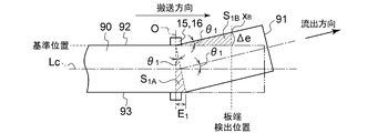
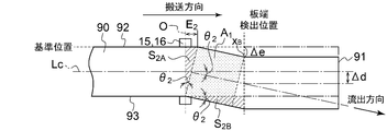
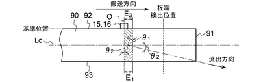
- 12A to 12D are diagrams showing state transitions of the metal plate 90 when the rolling apparatus 2 is operated based on the flowchart shown in FIG.
- FIG. 13 is a graph for explaining an example of a method for calculating the first elongation difference and the second elongation difference of the metal plate 90.
- the horizontal axis represents time and the vertical axis represents the deviation amount ⁇ e described later.
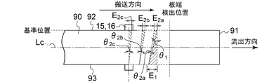
- Is shown. 15A to 15D are diagrams showing state transitions of the metal plate 90 when the rolling apparatus 2 is operated based on the flowchart shown in FIG.
- the metal plate 90 while rolling the metal plate 90 with a pair of rolling rolls 15 and 16 in a state where the output tension applied to the metal plate 90 is zero (that is, the metal plate 90 (While performing non-tensile rolling at the tip), using the second plate edge detection unit 34, at the positions on the outlet side of the pair of rolling rolls 15 and 16 (“plate edge detection positions” shown in FIGS. 12A to 12D), the metal plate The plate edge position x B in the plate width direction of 90 is detected (step S202; detection step).
- the time t20 is the time when the tip tensionless rolling of the metal plate 90 is started.
- the deviation amount ⁇ e of the plate end position xB detected in step S202 from the reference position in the plate width direction to one side in the plate width direction (one side of the first end edge 92 or the second end edge 93) is determined. It is calculated (step S204), and the calculated deviation amount ⁇ e is compared with the threshold value ⁇ e_th (step S206).
- the reference position is a specific position in the plate width direction when the longitudinal direction of the metal plate 90 is parallel to the transport direction by the rolling apparatus 2 (the direction orthogonal to the central axes of the rolling rolls 15 and 16). Is.
- the position of the first edge 92 of the metal plate 90 when the longitudinal direction of the metal plate 90 is parallel to the transport direction by the rolling apparatus 2 is defined as the “reference position”.
- the center position (position of the center line Lc) in the plate width direction of the metal plate 90 when the longitudinal direction of the metal plate 90 is parallel to the transport direction by the rolling apparatus 2 may be set as the “reference position”.
- step S206 it is determined that the deviation amount ⁇ e is smaller than the threshold value (NO in step S206), the process returns to step S202, and the plate edge position x B is detected again by the second plate edge detection unit 34.
- FIG. 12B shows a stage in which the tip of the metal plate 90 is bent due to some disturbance (for example, unevenness of the plate thickness in the plate width direction of the metal plate 90) from the state shown in FIG. 12A.
- the plate end position x B detected in step S202 deviates from the reference position to the first end edge 92 side (one side) in the plate width direction. That is, the outflow direction of the metal plate 90 from the rolling rolls 15 and 16 is deviated to the first edge 92 side (one side) in the plate width direction with respect to the transport direction by the rolling rolls 15 and 16.
- the deviation amount ⁇ e calculated in step S204 becomes larger than zero.
- the deviation amount ⁇ e starts to become larger than zero at time t21, and the deviation amount ⁇ e becomes maximum (state shown in FIG. 12B) at time t23.
- step S204 When the deviation amount ⁇ e calculated in step S204 is equal to or less than the threshold value ⁇ e_th (NO in step S206), the process returns to step S202, and the plate edge position x B is detected again by the second plate edge detection unit 34.
- the deviation amount ⁇ e calculated in step S204 becomes larger than the threshold value ⁇ e_th (YES in step S206, time t23 in the graph of FIG. 13)
- the rolling element 22 so that the deviation amount ⁇ e becomes zero in step S208.
- the leveling of the rolling rolls 15 and 16 is controlled according to the above (step S208).
- step S208 rolling leveling control of the pair of rolling rolls 15 and 16 is performed so that the outflow direction of the metal plate 90 from the rolling rolls 15 and 16 follows the transport direction of the metal plate 90 in the rolling apparatus 2.
- FIG. 12C is a diagram showing a stage at the end of step S208 (when the above-mentioned deviation amount ⁇ e becomes zero; time t24 in the graph of FIG. 13).
- step S208 The metal until the plate edge position x B detected by the second plate edge detection unit 34 in the first leveling step (step S208) described above returns to the reference position (until the state shown in FIG. 12C).
- the first elongation difference E1 relative to the one side (first edge 92 side) on the other side (here, the second edge 93 side) of the plate 90 is calculated (step S210; elongation difference calculation step).
- a plate edge position x B in the first leveling step is returned to the reference position (up to time t24) in the graph of FIG. 13, the time shift amount ⁇ e of the plate edge position x B integral with respect to the reference position
- the first elongation difference E1 is calculated based on (area S 1B'shown in Graph FIG. 13).
- the first elongation difference E1 can be calculated based on the area S 1B'shown in FIG.
- the remaining time Tc until the tip 91 of the metal plate 90 reaches the winding device 14 provided on the downstream side of the pair of rolling rolls 15 and 16 is calculated (step S212; remaining time calculation step).
- the starting point of the remaining time Tc is, for example, the time when the above-mentioned deviation amount ⁇ e becomes zero in the first leveling step (the end time of step S208; the time t24 in the graph of FIG. 13), or the start of the second leveling step. It may be a time point (the start time point of steps S214 to S218 described later; time t25 in the graph of FIG. 13). In the graph of FIG. 13, the time from the start time (time t25) of the second leveling step to the time t27 is the remaining time Tc.
- the remaining time Tc can be calculated based on the distance between the tip 91 of the metal plate 90 and the winding device 14, and the transport speed of the metal plate 90.
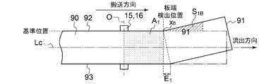
- FIG. 12D shows a state at the time when the second leveling step is completed (that is, a state at the end of step S218).
- step S214 the drive motors of the reduction device 22 and the rolling rolls 15 and 16 are provided so as to give the metal plate 90 a second elongation difference E2 (see FIG. 12D) having a magnitude equal to that of the first elongation difference E2 within the remaining time Tc.
- the second elongation difference E2 is a second elongation difference relative to the other side (here, the second end edge 93 side) on the one side (here, the first end edge 92 side) of the metal plate 90. is there.
- the plate end position x B shifts to the second edge 93 side, and a shift amount ⁇ e occurs.
- time integral value of ⁇ e in the second edge 93 side (the area S 2B in the graph of FIG. 13 ') is, the area S 2A in the graph of FIG. 13' becomes equal to, leveling of the rolling rolls 15 and 16 control by performing, as a triangle indicated by symbol S 2B in FIG. 12D are formed, it is possible to provide a second differential expansion E2 (see FIG. 12D) with respect to the metal plate 90.
- the triangle indicated by the symbol S 2B in FIG. 12D and the area S 2B'of the graph of FIG. 13 have a specific correlation, and the triangle indicated by the reference numeral S 2A and the triangle indicated by the reference numeral S 2B in FIG. This is because is similar to.
- step S216 the leveling control of the rolling rolls 15 and 16 is performed based on the control command value calculated in step S214.
- the control of step S216 is repeated while the difference
- the first elongation difference E1 caused by the bending of the tip of the metal plate 90 indicates the magnitude of the deviation of the metal plate 90 to one side in the plate width direction in the outflow direction.
- the first elongation difference E1 caused by the bending of the tip of the metal plate 90 is calculated, and the above-mentioned second elongation difference E2 is rolled so as to be equal to the above-mentioned first elongation difference E1. Rolling down leveling control of rolls 15 and 16 is performed.
- the elongation (second elongation) equal to the elongation (elongation corresponding to the first elongation difference E1) generated on one end side (here, the first end edge 92 side) of the metal plate 90 due to the bending of the tip of the metal plate 90. Since the reduction leveling control is performed so as to give the elongation corresponding to the difference E2 to the other end side of the metal plate 90 (here, the second end edge 93 side), the bending of the tip of the metal plate 90 is appropriately corrected. However, the tip edge (tip 91) of the metal plate 90 can be brought close to parallel to the axial direction of the winding device 14. Therefore, the metal plate that has been rolled without tension at the tip can be appropriately wound by the winding device.
- the above-mentioned first elongation difference E1 generated in the metal plate 90 due to the bending of the tip of the metal plate 90 has a correlation with the time integration of the deviation amount ⁇ e of the plate end position x B with respect to the above-mentioned reference position, and is typically Has a proportional relationship between the first elongation difference E1 and the time integration of the above-mentioned deviation amount ⁇ e.
- the first elongation difference E1 can be appropriately calculated based on the time integration of the above-mentioned deviation amount ⁇ e.
- the tip bending of the metal plate 90 is appropriately performed by performing the reduction leveling control so as to give the metal plate 90 a second elongation difference E2 equal to the first elongation difference E1 calculated in this way. It can be corrected.
- the remaining time Tc until the tip 91 of the metal plate 90 reaches the winding device 14 is calculated, and the second remaining time Tc is within the calculated remaining time Tc. Since the elongation difference E2 is given to the metal plate 90, the bending of the tip of the metal plate 90 can be appropriately corrected before the metal plate 90 starts winding.
- the first elongation difference E1 is calculated based on the time integration of the amount of deviation ⁇ e of the detected plate edge position x B with respect to the reference position, and the rolling roll 15 is based on the first elongation difference E1.
- 16 rolling down leveling control was performed.
- the reduction leveling control of the rolling rolls 15 and 16 is controlled based on the deviation angle of the metal plate 90 with respect to the transport direction in the outflow direction when the tip of the metal plate 90 is bent. I do. More specifically, in the embodiment according to the flowchart of FIG.
- the second deviation angle ⁇ 2 (see FIG. 15C) to the other side (here, the second edge 93 side) with respect to the transport direction in the outflow direction during the execution of the second leveling step.
- steps S302, S304, S306, S312, S316, and S318 are the same as those of steps S202, S204, S206, S212, S216, and S218 shown in FIG. 11, so detailed description thereof will be omitted.
- step S304 when the deviation amount ⁇ e calculated in step S304 based on the plate edge position x B detected in step S302 (detection step) is larger than the threshold value (YES in step S306), this The first deviation angle ⁇ 1 (here, the first edge 92 side) with respect to the transport direction of the outflow direction of the metal plate 90 at the time point (the start time of the first leveling step; the step shown in FIG. 15B). 15B) is acquired (step S308).
- the first deviation angle ⁇ 1 may be acquired based on the image captured by an imaging device or the like.
- step S310 based on the first deviation angle ⁇ 1 acquired in step S308, the second deviation angle ⁇ 2 to be given to the metal plate 90 in the second leveling step, that is, the other side of the metal plate 90 with respect to the transport direction in the outflow direction (
- the second deviation angle ⁇ 2 with respect to the second edge 93 side) is determined (step S310; see FIG. 15C).
- step S312 the rolling element 22 such that the deviation angle of the metal plate 90 toward the other side (here, the second end edge 93 side) becomes the above-mentioned second deviation angle ⁇ 2.
- step S314 the control command value for the drive motor of the rolling rolls 15 and 16 is calculated.
- step S316 the leveling control (first leveling step and second leveling step) of the rolling rolls 15 and 16 is performed (step S316).
- step S302 the metal plate detected in steps S302 to S306. Since the tip bending of the 90 has been corrected, the process returns to step S302 again to detect the tip bending of the metal plate 90 that may occur next.
- the first deviation angle ⁇ 1 with respect to the transport direction of the metal plate 90 in the outflow direction (here, the first end edge 92 side) caused by the bending of the tip of the metal plate 90 is the same as the above-mentioned first elongation difference E1.
- the magnitude of the deviation of the metal plate 90 toward one side (first end edge 92 side) in the plate width direction in the outflow direction is shown.
- the second deviation angle ⁇ 2 to the other side with respect to the transport direction in the outflow direction during the execution of the second leveling step can be appropriately determined based on the above-mentioned first deviation angle ⁇ 1. ..
- the tip bending of the metal plate 90 is appropriately corrected, and the tip edge of the metal plate 90 is wound. It can be brought close to parallel to the axial direction of the picking device 14. Therefore, the metal plate 90 that has been rolled without tension at the tip can be appropriately wound by the winding device 14.
- the second deviation angle ⁇ 2 determined in step S310 may be given to the metal plate 90 at once in the second leveling step of step S316 (see FIG. 15C), or may be divided into a plurality of times. , May be given to the metal plate 90 (see FIG. 15D).
- the angle ⁇ 2a is given for the first time, the angle ⁇ 2b for the second time, and the angle ⁇ 2c for the third time as the deviation angle of the metal plate 90 toward the other side (second end edge 93 side).
- the second leveling step is started within a time equal to or less than the time required for the first leveling step.
- the time required for the first leveling step (from the YES determination in step S206 in FIG. 11 to the end time in step S208) is shown in the graph of FIG. It is from time t22 to time t24.
- the time from the end of the first leveling step to the start of the second leveling step is from time t24 to t25 in the graph of FIG. 13, which is shorter than the time required for the first leveling step described above.
- the first leveling step and the second leveling step are performed without distinction (continuously) in step S316, and after the completion of the first leveling step, the second leveling is performed.
- the time to the start of the step is substantially zero, and the first leveling step (from the outflow direction of the metal plate 90 to one side (first end edge 92 side) to the return to the same direction as the transport direction). It is less than the required time.
- the second leveling step is started within the time required for the first leveling step, and the metal plate 90 is started.
- the outflow direction is shifted to the other side (second end edge 93 side). That is, after the completion of the first leveling step, the outflow direction of the metal plate 90 is shifted to the other side (second end edge 93 side) without much time, so that the metal plate 30 at the end of the second leveling step.
- the amount of deviation in the plate width direction ( ⁇ d shown in FIG. 12D) between the center position in the plate width direction at the tip bending portion and the center position in the plate width direction of the metal plate 90 on the rolling rolls 15 and 16 can be reduced.
- the area of the rectangular portion A1 shown in FIGS. 12C and 12D can be made as small as possible.
- the first leveling step and the second leveling step are continuously performed.
- the above-mentioned deviation amount ⁇ d becomes almost zero. Therefore, the metal plate 90 that has been rolled without tension at the tip can be more appropriately wound by the winding device 14.
- the control device for the rolling mill is A control device for controlling a rolling apparatus including a pair of rolling rolls provided so as to sandwich a metal plate.
- a first plate provided on the entry side of the pair of rolling rolls in the transport direction of the metal plate and configured to detect a plate end position in the plate width direction of the metal plate at the first position in the transport direction.
- Edge detector and A second plate edge detection unit provided on the exit side of the pair of rolling rolls in the transport direction and configured to detect the plate end position of the metal plate in the plate width direction at the second position in the transport direction.
- the said A determination unit configured to determine whether or not tip non-tension rolling, which is the rolling of the metal plate by the pair of rolling rolls, can be started in a state where the output tension of the metal plate is zero. To be equipped.
- the plate end positions (first plate end position and first plate end position) in the plate width direction of the metal plate. 2 Plate edge position) is detected. Therefore, based on these detection results, it is possible to grasp the degree of inclination of the metal plate with respect to the transport direction in the longitudinal direction before the start of the tip tensionless rolling, that is, the degree of inclination of the metal plate at the start of the tip tensionless rolling. It is possible to grasp the degree of inclination of the outflow direction with respect to the transport direction.
- the tip tensionless rolling it is determined whether or not the tip tensionless rolling can be started based on the detection results of the first plate end position and the second plate end position. Therefore, for example, the above-mentioned detection result. Therefore, when it is determined that the longitudinal direction of the metal plate (that is, the outflow direction of the metal plate at the start of rolling) is substantially parallel to the transport direction, it is possible to start the tipless tension rolling of the metal plate. It can be determined. Therefore, according to the configuration of (1) above, the tip tensionless rolling can be started in a state where the outflow direction of the metal plate and the transport direction are substantially parallel, so that the tip of the metal plate has a plate width from the transport line by the rolling mill. It is possible to suppress the deviation in the direction.
- the rolled metal plate can be easily wound appropriately by the winding device.
- the configuration of (1) above since the tip tensionless rolling can be started in a state where the outflow direction and the transport direction of the metal plate are substantially parallel, the second plate end position acquired at the start of the tip tensionless rolling.
- the rolling mill such as the meandering control of the metal plate, based on the position of the end of the second plate detected during the tip tensionless rolling. Therefore, it is possible to appropriately wind the metal plate that has been rolled without tension at the tip by the winding device.
- the determination unit is configured to determine that the tip tensionless rolling of the metal plate can be started when the difference between the first plate end position and the second plate end position is within a specified range. To.
- the difference between the first plate end position and the second plate end position is the inclination of the direction connecting the first plate end position and the second plate end position, that is, the longitudinal direction of the metal plate, with respect to the transport direction of the metal plate by the rolling mill. Indicates the degree. Further, the fact that the difference between the first plate end position and the second plate end position is zero indicates that the longitudinal direction of the metal plate is parallel to the transport direction.
- the configuration of (2) above when the difference between the first plate end position and the second plate end position is within the specified range, that is, the inclination of the metal plate with respect to the longitudinal direction is small. When it is close to parallel, it is determined that the tip non-tensile rolling of the metal plate is possible. Therefore, by starting the tip tensionless rolling of the metal plate according to this determination, it is possible to appropriately wind the rolled metal plate with the winding device as described in (1) above.
- the determination unit is used. It is configured to determine that the tip tensionless rolling of the metal plate can be started.
- the difference between the reference position and the first plate end position in the plate width direction and the difference between the same reference position and the second plate end position are the plate ends at the first position and the second position in the transport direction, respectively.
- the deviation of the first plate end position from the reference position and the deviation of the second plate end position from the reference position are relatively small, that is, in the longitudinal direction of the metal plate.
- the inclination with respect to the transport direction is small and close to parallel, it is determined that the tip tensionless rolling of the metal plate is possible. Therefore, by starting the tip tensionless rolling of the metal plate according to this determination, it is possible to appropriately wind the rolled metal plate with the winding device as described in (1) above.
- the control device of the rolling apparatus is A rolling control unit for controlling the operation of the pair of rolling rolls is further provided.
- the rolling control unit brings the pair of rolling rolls into contact with the metal plate, and then the pair of rolling rolls. Rotation of the pair of rolling rolls so that the gap between the pair of rolling rolls gradually decreases until the control value corresponding to the target plate thickness of the metal plate is reached as the metal plate is conveyed. It is configured to adjust the number and rolling amount.
- the tip of the metal plate that is not rolled by the rolling roll is rolled.
- the difference in plate thickness between the rolling and rolling parts may be large. In this case, when the metal plate is wound by the winding device, stress is concentrated on the boundary between the tip portion and the succeeding portion described above, and the metal plate may be cut at this boundary.
- the rolling rolls are rotated and rolled as the metal plate is conveyed.
- the number of rotations and the amount of rolling are adjusted so that the gap between the rolls gradually decreases until the control value corresponds to the target plate thickness of the metal plate. Therefore, a transition portion in which the plate thickness gradually decreases is formed between the tip portion having the same plate thickness as before rolling and the succeeding portion rolled to the target plate thickness. Therefore, it is possible to alleviate the stress concentration that may occur at the boundary between the tip portion and the trailing portion described above when the metal plate is wound by the winding device. This makes it possible to more appropriately wind the rolled metal plate with the winding device.
- the control device of the rolling apparatus is After the start of the tip tensionless rolling of the metal plate, when the detection result of the second plate end position by the second plate end detection unit deviates from the reference position to one side in the plate width direction, the rolling roll is released.
- a first leveling unit configured to control the reduction leveling of the pair of rolling rolls so that the outflow direction of the metal plate is along the transport direction of the metal plate in the rolling apparatus. After the reduction leveling control by the first leveling portion, the outflow direction of the metal plate from the rolling roll is shifted to the other side of the plate width direction with respect to the transport direction, and then the outflow direction of the metal plate is changed.
- a second leveling portion configured to control the reduction leveling of the pair of rolling rolls so as to return to the transport direction, and a second leveling portion. To be equipped.
- the plate end position in the plate width direction of the metal plate is detected at the position on the outlet side of the rolling roll. Based on the detected plate edge position deviating from the reference position to one side in the plate width direction, a deviation (bending of the tip of the metal plate) to one side in the plate width direction in the outflow direction of the metal plate occurred. Can be detected.
- the downflow leveling control is used to make the outflow direction of the metal plate follow the transport direction of the metal plate in the rolling apparatus, and then set the outflow direction of the metal plate to the transport direction.
- the rolling down leveling was controlled so that the outflow direction was along the transport direction after shifting to the other side in the width direction, the bending of the tip of the metal plate was corrected, and the tip edge of the metal plate was set in the axial direction of the winding device.
- the tip untensile rolling can be continued in a state of being close to parallel to. Therefore, according to the configuration (5) above, the metal plate that has been rolled without tension at the tip can be appropriately wound by the winding device.
- the rolling equipment according to at least one embodiment of the present invention is A pair of rolling rolls provided so as to sandwich a metal plate, The control device according to any one of (1) to (5) above, and To be equipped.
- the plate end positions (first plate end position and first plate end position) in the plate width direction of the metal plate. 2 Plate edge position) is detected. Therefore, based on these detection results, it is possible to grasp the degree of inclination of the metal plate with respect to the transport direction in the longitudinal direction before the start of the tip tensionless rolling, that is, the degree of inclination of the metal plate at the start of the tip tensionless rolling. It is possible to grasp the degree of inclination of the outflow direction with respect to the transport direction.
- the tip tensionless rolling can be started based on the detection results of the first plate end position and the second plate end position. Therefore, for example, the above-mentioned detection result. Therefore, when it is determined that the longitudinal direction of the metal plate (that is, the outflow direction of the metal plate at the start of rolling) is substantially parallel to the transport direction, it is possible to start the tipless tension rolling of the metal plate. It can be determined. Therefore, according to the configuration (6) above, the tip tensionless rolling can be started in a state where the outflow direction and the transport direction of the metal plate are substantially parallel, so that the tip portion of the metal plate is the plate width from the transport line by the rolling mill. It is possible to suppress the deviation in the direction.
- the rolled metal plate can be easily wound appropriately by the winding device.
- the configuration of (6) above since the tip tensionless rolling can be started in a state where the outflow direction and the transport direction of the metal plate are substantially parallel, the second plate end position acquired at the start of the tip tensionless rolling.
- the rolling mill such as the meandering control of the metal plate, based on the position of the end of the second plate detected during the tip tensionless rolling. Therefore, it is possible to appropriately wind the metal plate that has been rolled without tension at the tip by the winding device.
- a winding device provided on the downstream side of the second plate end detection unit in the transport direction is provided.
- the distance between the pair of rolling rolls and the winding device in the conveying direction is L2
- the distance between the pair of rolling rolls and the second plate end detecting portion in the conveying direction is 0.1 ⁇ L2. It is as follows.
- the position of the tip of the metal plate in the transport direction is set to the second plate. It must be located on the same side as the detection unit or on the downstream side.
- the distance between the second plate edge detection portion and the rolling roll is relatively short in the transport direction, so that the tip position of the metal plate at the start of non-tension rolling can be determined. It is possible to detect the position of the end of the second plate at the start of non-tensile rolling and during non-tensile rolling while keeping the rolling rolls relatively close to each other. Therefore, it is possible to appropriately perform the tip tensionless rolling while shortening the length of the unrolled tip portion of the metal plate, thereby improving the yield of the metal plate.
- an unwinding device provided on the upstream side of the first plate edge detection unit in the transport direction is provided.
- the distance between the pair of rolling rolls and the unwinding device in the transport direction is L1
- the distance between the pair of rolling rolls and the first plate end detection unit in the transport direction is 0.1 ⁇ L1. It is as follows.
- the transport direction of the metal plate is reversed in the second pass after the completion of the first pass, and after the metal plate. Rolling with a rolling roll is started from the end side.
- the distance between the first plate edge detection unit and the rolling roll is relatively short in the transport direction in the second pass (opposite to the transport direction in the first pass). Therefore, it is possible to detect the position of the end of the first plate at the start of non-tensile rolling and during non-tensile rolling while keeping the rear end position of the metal plate at the start of the second pass of non-tensile rolling relatively close to the rolling roll. Is. Therefore, the tip tensionless rolling can be appropriately performed while shortening the length of the rear end portion of the metal plate that is not rolled, and thus the yield of the metal plate can be improved.
- the rolling equipment A plate thickness gauge provided on at least one of the inlet side and the outlet side of the pair of rolling rolls in the transport direction and configured to measure the plate thickness of the metal plate is provided.
- the first plate edge detection unit or the second plate edge detection unit is located between the pair of rolling rolls and the plate thickness gauge in the transport direction.
- the plate thickness gauge used to control the plate thickness of the metal plate is preferably provided near the rolling roll in the transport direction in order to improve the control response.
- the first plate end detection unit or the second plate end detection unit is provided closer to the rolling roll than the plate thickness gauge for measuring the plate thickness of the metal plate. Therefore, it is possible to detect the first plate end position or the second plate end position at the start of non-tensile rolling and during non-tensile rolling while bringing the tip position of the metal plate closer to the rolling roll at the start of non-tensile rolling. .. Therefore, it is possible to appropriately perform the tip tensionless rolling while shortening the length of the unrolled tip portion of the metal plate, thereby improving the yield of the metal plate.
- the first plate edge detection unit or the second plate edge detection unit is configured to detect the first plate end position or the second plate end position using radiation.
- the rolling roll In the vicinity of the rolling roll, a large amount of rolling oil and fume are scattered, the rolling roll vibrates, and it is often a harsh environment such as darkness.
- the first plate edge detection unit or the second plate edge detection unit that detects the plate edge position by using radiation is used, the rolling roll in a harsh environment. Even if it is placed in the vicinity of, the plate edge position can be detected appropriately.
- the rolling equipment A pair of first rolling rolls, which are the pair of rolling rolls, A pair of second rolling rolls, which are provided on the downstream side of the pair of first rolling rolls in the transport direction and are the pair of rolling rolls, An unwinding device provided on the upstream side of the pair of first rolling rolls, A take-up device provided on the downstream side of the pair of second rolling rolls is provided.
- the control device determines whether or not the first tip tensileless rolling of the metal plate can be started in the pair of first rolling rolls, and it is determined that the first tip tensileless rolling can be started. After the tip tensionless rolling by the pair of first rolling rolls is started, it is configured to determine whether or not the second tip tensionless rolling of the metal plate in the pair of second rolling rolls can be started. ..
- the method of operating the rolling mill according to at least one embodiment of the present invention is as follows.
- a method of operating a rolling apparatus including a pair of rolling rolls provided so as to sandwich a metal plate.
- a first plate edge detection step for detecting a first plate end position, which is a plate end position in the plate width direction of the metal plate, at a first position on the entry side of the pair of rolling rolls in the transport direction of the metal plate.
- a second plate edge detection step for detecting a second plate end position, which is a plate end position in the plate width direction of the metal plate, at a second position on the exit side of the pair of rolling rolls in the transport direction.
- the protruding side tension of the metal plate A determination step for determining whether or not tip tensionless rolling, which is rolling of the metal plate by the pair of rolling rolls in a state of zero, can be started, and To be equipped.
- the plate end positions (first plate end position and first plate end position) in the plate width direction of the metal plate. 2 Plate edge position) is detected. Therefore, based on these detection results, it is possible to grasp the degree of inclination of the metal plate with respect to the transport direction in the longitudinal direction before the start of the tip tensionless rolling, that is, the degree of inclination of the metal plate at the start of the tip tensionless rolling. It is possible to grasp the degree of inclination of the outflow direction with respect to the transport direction.
- the propriety of starting the tip tensionless rolling is determined based on the detection results of the first plate end position and the second plate end position. Therefore, for example, the above-mentioned detection result. Therefore, when it is determined that the longitudinal direction of the metal plate (that is, the outflow direction of the metal plate at the start of rolling) is substantially parallel to the transport direction, it is possible to start the tipless tension rolling of the metal plate. It can be determined. Therefore, according to the method (12) above, the tip tensionless rolling can be started in a state where the outflow direction and the transport direction of the metal plate are substantially parallel, so that the tip portion of the metal plate is the plate width from the transport line by the rolling mill. It is possible to suppress the deviation in the direction.
- the rolled metal plate can be easily wound appropriately by the winding device.
- the tip tensionless rolling can be started in a state where the outflow direction and the transport direction of the metal plate are substantially parallel, so that the second plate end position acquired at the start of the tip tensionless rolling.
- the present invention is not limited to the above-described embodiments, and includes a modified form of the above-described embodiments and a combination of these embodiments as appropriate.
- the expression representing a shape such as a quadrangular shape or a cylindrical shape not only represents a shape such as a quadrangular shape or a cylindrical shape in a geometrically strict sense, but also within a range in which the same effect can be obtained.
- the shape including the uneven portion, the chamfered portion, etc. shall also be represented.
- the expression “comprising”, “including”, or “having” one component is not an exclusive expression excluding the existence of another component.
Landscapes
- Engineering & Computer Science (AREA)
- Mechanical Engineering (AREA)
- Control Of Metal Rolling (AREA)
Priority Applications (4)
| Application Number | Priority Date | Filing Date | Title |
|---|---|---|---|
| JP2021530449A JP7150994B2 (ja) | 2019-07-11 | 2019-07-11 | 圧延装置の制御装置及び圧延設備並びに圧延装置の運転方法 |
| EP19937138.6A EP3974074B1 (en) | 2019-07-11 | 2019-07-11 | Control device for rolling mill device, rolling mill facility, and method for operating rolling mill device |
| PCT/JP2019/027491 WO2021005778A1 (ja) | 2019-07-11 | 2019-07-11 | 圧延装置の制御装置及び圧延設備並びに圧延装置の運転方法 |
| CN201980097659.4A CN114007771B (zh) | 2019-07-11 | 2019-07-11 | 轧制装置的控制装置以及轧制设备及轧制装置的运转方法 |
Applications Claiming Priority (1)
| Application Number | Priority Date | Filing Date | Title |
|---|---|---|---|
| PCT/JP2019/027491 WO2021005778A1 (ja) | 2019-07-11 | 2019-07-11 | 圧延装置の制御装置及び圧延設備並びに圧延装置の運転方法 |
Publications (1)
| Publication Number | Publication Date |
|---|---|
| WO2021005778A1 true WO2021005778A1 (ja) | 2021-01-14 |
Family
ID=74114450
Family Applications (1)
| Application Number | Title | Priority Date | Filing Date |
|---|---|---|---|
| PCT/JP2019/027491 Ceased WO2021005778A1 (ja) | 2019-07-11 | 2019-07-11 | 圧延装置の制御装置及び圧延設備並びに圧延装置の運転方法 |
Country Status (4)
| Country | Link |
|---|---|
| EP (1) | EP3974074B1 (https=) |
| JP (1) | JP7150994B2 (https=) |
| CN (1) | CN114007771B (https=) |
| WO (1) | WO2021005778A1 (https=) |
Cited By (1)
| Publication number | Priority date | Publication date | Assignee | Title |
|---|---|---|---|---|
| WO2025062607A1 (ja) * | 2023-09-22 | 2025-03-27 | Primetals Technologies Japan株式会社 | 圧延装置用の制御装置、圧延設備及び圧延装置の運転方法 |
Families Citing this family (1)
| Publication number | Priority date | Publication date | Assignee | Title |
|---|---|---|---|---|
| WO2025224989A1 (ja) * | 2024-04-26 | 2025-10-30 | Primetals Technologies Japan株式会社 | 圧延装置用の制御装置、圧延設備及び圧延装置の運転方法 |
Citations (7)
| Publication number | Priority date | Publication date | Assignee | Title |
|---|---|---|---|---|
| JPS458780B1 (https=) * | 1966-10-12 | 1970-03-30 | ||
| JPS4996955A (https=) * | 1973-01-20 | 1974-09-13 | ||
| JPH0220608A (ja) * | 1988-07-05 | 1990-01-24 | Sumitomo Metal Ind Ltd | 圧延材の蛇行制御方法 |
| JPH07132310A (ja) * | 1993-11-10 | 1995-05-23 | Mitsubishi Heavy Ind Ltd | 圧延方法 |
| JPH11179414A (ja) | 1997-12-24 | 1999-07-06 | Nkk Corp | 冷間圧延機における片伸び量推定方法及び形状制御方法 |
| JP2014117743A (ja) * | 2012-12-19 | 2014-06-30 | Jfe Steel Corp | 圧延材の蛇行制御方法、圧延材の蛇行制御装置、圧延材の蛇行制御プログラム、及び圧延材の製造方法 |
| JP2018158365A (ja) * | 2017-03-23 | 2018-10-11 | Jfeスチール株式会社 | 熱間圧延方法及び熱間圧延装置 |
Family Cites Families (7)
| Publication number | Priority date | Publication date | Assignee | Title |
|---|---|---|---|---|
| AUPO928797A0 (en) * | 1997-09-19 | 1997-10-09 | Bhp Steel (Jla) Pty Limited | Strip steering |
| AT410767B (de) * | 2001-10-24 | 2003-07-25 | Voest Alpine Ind Anlagen | Verfahren und vorrichtung zur kontinuierlichen herstellung eines gewalzten metallbandes aus einermetallschmelze |
| KR101018124B1 (ko) * | 2003-09-18 | 2011-02-25 | 주식회사 포스코 | 열간 압연 공정에서의 스트립의 사행 및 편파 레벨링 제어장치 |
| DE102004060342B3 (de) * | 2004-12-15 | 2006-07-27 | Siemens Ag | Betriebsverfahren für eine Walzstraße und hiermit korrespondierende Einrichtungen |
| CN103252358B (zh) * | 2013-05-21 | 2014-12-31 | 东北大学 | 一种宽厚板镰刀弯矫正方法 |
| CN104307892B (zh) * | 2014-11-06 | 2016-04-13 | 广西柳州银海铝业股份有限公司 | 连轧穿带过程中带材头部纠偏的方法 |
| CN106513443B (zh) * | 2016-12-27 | 2018-12-11 | 奎克化学(中国)有限公司 | 一种安装有带材自动对中装置的四辊可逆轧机及其纠偏方法 |
-
2019
- 2019-07-11 WO PCT/JP2019/027491 patent/WO2021005778A1/ja not_active Ceased
- 2019-07-11 CN CN201980097659.4A patent/CN114007771B/zh active Active
- 2019-07-11 EP EP19937138.6A patent/EP3974074B1/en active Active
- 2019-07-11 JP JP2021530449A patent/JP7150994B2/ja active Active
Patent Citations (7)
| Publication number | Priority date | Publication date | Assignee | Title |
|---|---|---|---|---|
| JPS458780B1 (https=) * | 1966-10-12 | 1970-03-30 | ||
| JPS4996955A (https=) * | 1973-01-20 | 1974-09-13 | ||
| JPH0220608A (ja) * | 1988-07-05 | 1990-01-24 | Sumitomo Metal Ind Ltd | 圧延材の蛇行制御方法 |
| JPH07132310A (ja) * | 1993-11-10 | 1995-05-23 | Mitsubishi Heavy Ind Ltd | 圧延方法 |
| JPH11179414A (ja) | 1997-12-24 | 1999-07-06 | Nkk Corp | 冷間圧延機における片伸び量推定方法及び形状制御方法 |
| JP2014117743A (ja) * | 2012-12-19 | 2014-06-30 | Jfe Steel Corp | 圧延材の蛇行制御方法、圧延材の蛇行制御装置、圧延材の蛇行制御プログラム、及び圧延材の製造方法 |
| JP2018158365A (ja) * | 2017-03-23 | 2018-10-11 | Jfeスチール株式会社 | 熱間圧延方法及び熱間圧延装置 |
Non-Patent Citations (1)
| Title |
|---|
| See also references of EP3974074A4 |
Cited By (1)
| Publication number | Priority date | Publication date | Assignee | Title |
|---|---|---|---|---|
| WO2025062607A1 (ja) * | 2023-09-22 | 2025-03-27 | Primetals Technologies Japan株式会社 | 圧延装置用の制御装置、圧延設備及び圧延装置の運転方法 |
Also Published As
| Publication number | Publication date |
|---|---|
| CN114007771B (zh) | 2023-06-16 |
| EP3974074A1 (en) | 2022-03-30 |
| JPWO2021005778A1 (https=) | 2021-01-14 |
| EP3974074A4 (en) | 2022-05-18 |
| EP3974074C0 (en) | 2023-12-27 |
| CN114007771A (zh) | 2022-02-01 |
| JP7150994B2 (ja) | 2022-10-11 |
| EP3974074B1 (en) | 2023-12-27 |
Similar Documents
| Publication | Publication Date | Title |
|---|---|---|
| WO2021005777A1 (ja) | 圧延装置の運転方法並びに圧延装置の制御装置及び圧延設備 | |
| KR101136775B1 (ko) | 웨브 반송 장치, 웨브 반송 방법 및 웨브 반송 제어 프로그램을 저장한 컴퓨터 판독가능 매체 | |
| KR101593812B1 (ko) | 압연 제어 장치, 압연 제어 방법 및 기록 매체 | |
| CN112334243B (zh) | 轧制装置的控制装置、轧制设备以及轧制装置的运转方法 | |
| WO2021005778A1 (ja) | 圧延装置の制御装置及び圧延設備並びに圧延装置の運転方法 | |
| JP6028496B2 (ja) | 巻取装置及び鋼板尾端停止位置の制御方法 | |
| JP2000298519A (ja) | 金属帯の通板位置制御方法 | |
| JP2007039161A (ja) | 搬送装置、記録システムおよび搬送方法 | |
| JP6540644B2 (ja) | 巻取装置及び鋼板尾端停止位置の制御方法 | |
| CN103379969B (zh) | 轧制控制装置及轧制控制方法 | |
| JP7076328B2 (ja) | 搬送装置の制御方法及び搬送装置 | |
| JP7020445B2 (ja) | 巻取装置の尾端停止位置制御方法、尾端停止位置制御装置及び巻取装置 | |
| WO2025062607A1 (ja) | 圧延装置用の制御装置、圧延設備及び圧延装置の運転方法 | |
| US12179244B2 (en) | Control device for rolling mill apparatus, rolling mill facility, and operation method for rolling mill apparatus | |
| JP7770747B2 (ja) | ワークロール開閉装置 | |
| US12192425B2 (en) | Image reading device having measuring section with encoder | |
| JPH1128513A (ja) | 熱間圧延ラインにおける金属帯の巻取り方法および巻取りコイラ | |
| JP4712580B2 (ja) | リバース圧延における蛇行制御方法 | |
| WO2024161619A1 (ja) | 疵検出装置、圧延装置、疵検出方法及び圧延方法 | |
| JPH0910836A (ja) | 鋼帯尾端の蛇行防止方法及びその装置 | |
| JP2019156551A (ja) | 搬送装置及び搬送方法 |
Legal Events
| Date | Code | Title | Description |
|---|---|---|---|
| 121 | Ep: the epo has been informed by wipo that ep was designated in this application |
Ref document number: 19937138 Country of ref document: EP Kind code of ref document: A1 |
|
| ENP | Entry into the national phase |
Ref document number: 2021530449 Country of ref document: JP Kind code of ref document: A |
|
| ENP | Entry into the national phase |
Ref document number: 2019937138 Country of ref document: EP Effective date: 20211220 |
|
| NENP | Non-entry into the national phase |
Ref country code: DE |