WO2020255568A1 - 回転体装着装置、油捕集装置及びレンジフード - Google Patents
回転体装着装置、油捕集装置及びレンジフード Download PDFInfo
- Publication number
- WO2020255568A1 WO2020255568A1 PCT/JP2020/018239 JP2020018239W WO2020255568A1 WO 2020255568 A1 WO2020255568 A1 WO 2020255568A1 JP 2020018239 W JP2020018239 W JP 2020018239W WO 2020255568 A1 WO2020255568 A1 WO 2020255568A1
- Authority
- WO
- WIPO (PCT)
- Prior art keywords
- rotating body
- attachment
- detachment
- power shaft
- mounting device
- Prior art date
- Legal status (The legal status is an assumption and is not a legal conclusion. Google has not performed a legal analysis and makes no representation as to the accuracy of the status listed.)
- Ceased
Links
Images


Classifications
-
- F—MECHANICAL ENGINEERING; LIGHTING; HEATING; WEAPONS; BLASTING
- F24—HEATING; RANGES; VENTILATING
- F24C—DOMESTIC STOVES OR RANGES ; DETAILS OF DOMESTIC STOVES OR RANGES, OF GENERAL APPLICATION
- F24C15/00—Details
- F24C15/20—Removing cooking fumes
- F24C15/2078—Removing cooking fumes movable
- F24C15/2092—Removing cooking fumes movable extendable or pivotable
-
- F—MECHANICAL ENGINEERING; LIGHTING; HEATING; WEAPONS; BLASTING
- F16—ENGINEERING ELEMENTS AND UNITS; GENERAL MEASURES FOR PRODUCING AND MAINTAINING EFFECTIVE FUNCTIONING OF MACHINES OR INSTALLATIONS; THERMAL INSULATION IN GENERAL
- F16D—COUPLINGS FOR TRANSMITTING ROTATION; CLUTCHES; BRAKES
- F16D1/00—Couplings for rigidly connecting two coaxial shafts or other movable machine elements
- F16D1/10—Quick-acting couplings in which the parts are connected by simply bringing them together axially
- F16D1/108—Quick-acting couplings in which the parts are connected by simply bringing them together axially having retaining means rotating with the coupling and acting by interengaging parts, i.e. positive coupling
- F16D1/116—Quick-acting couplings in which the parts are connected by simply bringing them together axially having retaining means rotating with the coupling and acting by interengaging parts, i.e. positive coupling the interengaging parts including a continuous or interrupted circumferential groove in the surface of one of the coupling parts
-
- F—MECHANICAL ENGINEERING; LIGHTING; HEATING; WEAPONS; BLASTING
- F24—HEATING; RANGES; VENTILATING
- F24C—DOMESTIC STOVES OR RANGES ; DETAILS OF DOMESTIC STOVES OR RANGES, OF GENERAL APPLICATION
- F24C15/00—Details
- F24C15/20—Removing cooking fumes
-
- F—MECHANICAL ENGINEERING; LIGHTING; HEATING; WEAPONS; BLASTING
- F24—HEATING; RANGES; VENTILATING
- F24C—DOMESTIC STOVES OR RANGES ; DETAILS OF DOMESTIC STOVES OR RANGES, OF GENERAL APPLICATION
- F24C15/00—Details
- F24C15/20—Removing cooking fumes
- F24C15/2035—Arrangement or mounting of filters
-
- F—MECHANICAL ENGINEERING; LIGHTING; HEATING; WEAPONS; BLASTING
- F24—HEATING; RANGES; VENTILATING
- F24C—DOMESTIC STOVES OR RANGES ; DETAILS OF DOMESTIC STOVES OR RANGES, OF GENERAL APPLICATION
- F24C15/00—Details
- F24C15/20—Removing cooking fumes
- F24C15/2071—Removing cooking fumes mounting of cooking hood
-
- F—MECHANICAL ENGINEERING; LIGHTING; HEATING; WEAPONS; BLASTING
- F24—HEATING; RANGES; VENTILATING
- F24F—AIR-CONDITIONING; AIR-HUMIDIFICATION; VENTILATION; USE OF AIR CURRENTS FOR SCREENING
- F24F7/00—Ventilation
- F24F7/007—Ventilation with forced flow
- F24F7/013—Ventilation with forced flow using wall or window fans, displacing air through the wall or window
-
- F—MECHANICAL ENGINEERING; LIGHTING; HEATING; WEAPONS; BLASTING
- F24—HEATING; RANGES; VENTILATING
- F24F—AIR-CONDITIONING; AIR-HUMIDIFICATION; VENTILATION; USE OF AIR CURRENTS FOR SCREENING
- F24F7/00—Ventilation
- F24F7/04—Ventilation with ducting systems, e.g. by double walls; with natural circulation
- F24F7/06—Ventilation with ducting systems, e.g. by double walls; with natural circulation with forced air circulation, e.g. by fan positioning of a ventilator in or against a conduit
Definitions
- the present invention relates to a rotating body mounting device in a range hood or the like.
- the range hood includes a rotating body such as a propeller fan, a sirocco fan, and a turbo fan for exhausting air, and a rotating body such as a grease filter for collecting oil, dust, and the like.
- These rotating bodies are rotated by a motor to recover the exhaust gas and the oil contained in the exhaust gas. Since oil and the like derived from oil smoke generated by cooking easily adhere to rotating bodies such as fans and grease filters, regular cleaning is required. Therefore, in order to clean the dirty rotating body, it is necessary to periodically remove the rotating body from the drive shaft.
- the boss cylinder and the impeller main body can be separated by removing a mounting knob with a screw called a spinner.
- An object of the present invention is to provide a rotating body mounting device with improved workability for attaching and detaching to and from a power shaft.
- a aspect of claim 1 of the present invention is a rotating body mounting device 30 inserted into a power shaft 20 including a rotating body and a mounting device 302, in which the mounting device 302 is an insertion hole into which the power shaft 20 is inserted.
- the rotating body mounting device is attached to the power shaft 20 on the side where the power shaft 20 is not inserted into the mounting device 302 with reference to the rotating body. It has a power shaft attachment / detachment mechanism operation unit to be attached / detached, and the rotating body is attached / detached from the rotating body mounting device 30 on the side where the power shaft 20 is inserted into the mounting device 302 with reference to the rotating body.
- the problem was solved by using a rotating body mounting device 30 having a mechanism operating unit.
- the rotating body mounting device 30 including the rotating body and the mounting device 302 can be easily removed from the power shaft 20 while being integrated. Further, by providing the rotating body attachment / detachment mechanism operation unit of the mounting device on the side where the power shaft 20 is inserted into the mounting device 302 with the rotating body as a reference, the rotating body mounting device 30 is mounted on the power shaft 20.
- the rotating body attachment / detachment mechanism operation part of the mounting device is located at the back of the rotating body and is out of reach. Therefore, the rotating body mounting device 30 is configured so that the rotating body attachment / detachment mechanism operation unit of the mounting device cannot be operated until the rotating body mounting device 30 is removed as described above. This makes it possible to prevent accidentally operating the rotating body attachment / detachment mechanism operation unit of the mounting device while the rotating body mounting device 30 is mounted on the power shaft 20.
- the mounting device 302 includes a detachable device 40 having the power shaft attachment / detachment mechanism operation unit and a rotating body holding device 50 having the rotating body attachment / detachment mechanism operation unit 5011.
- the rotating body mounting device 30 described in 1 may be used.
- the attachment / detachment device 40 includes a boss cylinder 431 to be inserted into the rotating body, and the rotating body attachment / detachment mechanism operation unit 5011 of the rotating body holding device 50 is the boss cylinder.
- the rotating body mounting device 30 according to claim 2, characterized in that the 431 is provided so as to hold and release the 431.
- the rotating body mounting device 30 can be disassembled into three members, the attaching / detaching device 40, the rotating body, and the rotating body holding device 50, by one operation of the rotating body attaching / detaching mechanism operation unit 5011. Further, it is possible to prevent the attachment / detachment device 40 and the rotating body holding device 50 from being accidentally separated from each other while the rotating body mounting device 30 is mounted on the power shaft 20.
- the attachment / detachment device 40 is provided with a tapered surface 4312 whose diameter is reduced toward the rotating body side, and the urging portion of the rotating body holding device 50 is tapered.
- the urging portion of the rotating body pressing device 50 can have two functions of holding and releasing the boss cylinder 431 and pressing the rotating body.
- the rotating body has a concave portion and / or a convex portion on the mounting surface of the detachable device and / or the rotating body holding device so as to be fitted therein.
- the rotating body mounting device 30 according to any one of claims 2 to 5, wherein the attachment / detachment device 40 and / or the rotating body holding device 50 is provided with a convex portion and / or a concave portion. May be.
- the rotating body when the rotating body is a grease filter (rotating body) 301, there are a front surface and a back surface, and when the rotating body is a sirocco fan, there are an upper surface and a lower surface. If the rotating body is not mounted on the correct surface of the attachment / detachment device 40 and the rotating body holding device 50, the rotating body may not function properly. In such a case, the rotating body erroneously turns upside down or upside down by having the detachable device side concave portion or the convex portion that fits into the rotating body side convex portion or the concave portion provided in the detachable device 40. It is possible to prevent the rotating body from being attached.
- the rotating body erroneously turns upside down or upside down by having the detachable device side concave portion or the convex portion that fits into the rotating body side convex portion or the concave portion provided in the detachable device 40. It is possible to prevent the rotating body from being attached.
- the rotating body pressing device may be provided with a rotating body side convex portion or a concave portion that fits into the rotating body pressing device side concave portion or the convex portion provided on the rotating body.
- the concave and / or convex portions of the rotating body are curved so that the mounting surface is curved so as to be a convex portion on the attachment / detachment device 40 side (curvature so as to be a concave portion when viewed from the rotating body holding device 50 side).
- the concave portion or the convex portion may be provided only on the attachment / detachment device 40 side of the mounting surface or only on the rotating body holding device 50 side.
- attachment / detachment device 40 side and the rotating body holding device 50 side may be provided with the concave / or convex portion so as to fit into the concave / or convex portion provided on the mounting surface of the rotating body.
- shape of the concave portion and the convex portion can be various.
- the rotating body has at least one engaging mechanism (3016, 3018), and the attaching / detaching device 40 or the rotating body holding device 50 has the engaging mechanism.
- the rotating body mounting device 30 according to any one of claims 2 to 6 having an engaged mechanism (434, 435) that engages with (3016, 3018) may be used. This has made it possible to reliably stop the rotating body from rotating.
- an oil trap including a rotating body mounting device 30 of the above aspect, a power device 4 for rotating the rotating body mounting device 30, and an oil collecting member 5 for collecting oil. It may be used as a collector. As a result, by adding the oil collecting member 5, it becomes easier to use the rotating body mounting device 30 even in an environment where oil easily adheres.
- the range hood 1 may be provided with the rotating body mounting device 30 or the oil collecting device of the above aspect.
- the rotating body mounting device and the oil collecting device included in the present invention can be used for various rotating bodies, and among them, the rotating body used in the range hood 1 includes a grease filter, a fan, and the like. , It was clarified that it can also be used for these.
- the rotating body mounting device including the rotating body and the mounting device can be attached to and detached from the power shaft in an integrated state, so that workability is improved.
- FIG. 1 Perspective view from the bottom side of the range hood with the current plate removed A perspective view from above of the range hood with a part of the blower box removed for explanation.
- FIG. 1 Perspective view of (A) grease filter drive motor (power unit) according to the first embodiment
- FIG. 1 Perspective view of (B) grease filter drive motor (power unit) according to the first embodiment
- FIG. 1 Perspective view of (B) grease filter drive motor (power unit) according to the first embodiment
- FIG. 1 Perspective view of (A) grease filter drive motor (power unit) according to the first embodiment
- FIG. 1 Perspective view of (A) grease filter drive motor (power unit) according to the first embodiment
- FIG. 1 Perspective view of (A) grease filter drive motor (power unit) according to the first embodiment
- FIG. 1 Perspective view of (A) grease filter drive motor (power unit) according to the first embodiment
- FIG. 1 Perspective view of (A) grease filter drive motor (power unit) according to the first embodiment
- FIG. 1 Perspective view of (A) grease filter drive motor (power unit) according
- Exploded view of the rotating body holding device according to the second embodiment (A) Enlarged view of the boss cylinder (B) A perspective view showing a holding relationship between the boss cylinder and the rotating body attachment / detachment mechanism according to the second embodiment.
- the conceptual diagram which shows the relationship between the boss cylinder holding member (bar spring which has a clamping action) and the tip portion of a boss cylinder which concerns on Example 2.
- the conceptual diagram which shows the mode of the urging part which concerns on Example 2.
- Exploded view showing the mounting relationship of the attachment / detachment device, the grease filter (rotating body), and the rotating body holding device according to the second embodiment.
- A) Perspective view (B) Perspective view of the rotating body holding device according to the third embodiment with the upper cover removed.
- Example 1 is an example in which the present invention is applied to the grease filter (rotating body) 301 of the range hood 1.
- FIG. 1 is a perspective view from the bottom surface side of the range hood 1 from which the straightening vane is removed, and shows a state in which the straightening vane covering the lower surface of the range hood 1 is removed.
- a grease filter (rotating body) 301 corresponding to a rotating body is attached by an attachment device 302.
- a bell mouth (oil collecting member) 5 that also functions as an oil collecting member is mounted around the grease filter (rotating body) 301.
- the rotating body mounting device 30 is composed of at least two members, a grease filter (rotating body) 301 and a mounting device 302.
- the mounting device 302 is a member located on both sides of the grease filter (rotating body) 301, and in FIG. 1, which is a perspective view from the bottom surface side, the lower side of the mounting device 302 is visible.
- the power shaft attachment / detachment mechanism operation unit 303 of the attachment device projects from both sides of the attachment device 302.
- the rotating body mounting device 30 When the power shaft attachment / detachment mechanism operation unit 303 of the attachment device is pressed, the rotating body mounting device 30 is disengaged from the power shaft (not shown) inserted in the rotating body mounting device 30.
- the specific structure is the same as that of the “1 attachment / detachment device A power shaft attachment / detachment mechanism” of the second embodiment described later. Since the rotating body mounting device 30 composed of the grease filter (rotating body) 301 and the mounting device 302 can be removed from the power shaft 20 while being integrated, if the worker holds the mounting device 302, the grease filter (rotating body) The grease filter (rotating body) 301 does not come off and fall even if the rotating body) 301 is not particularly supported.
- FIG. 2 is a perspective view from the upper side of the range hood 1 in which a part of the blower box is removed for explanation.
- a fan casing 6 is provided in the blower box, and a fan and a motor for driving the fan are housed in the fan casing 6.
- the grease filter drive motor (power device) 4 that drives the grease filter (rotating body) 301 is fixed on the grease filter drive motor crosspiece 7.
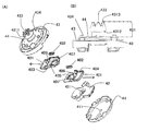
- FIG. 3 is a perspective view of (A) the grease filter drive motor (power device) 4 according to the first embodiment, and (B) the grease filter (rotating body) 301 and the mounting device 302 are mounted on the grease filter drive motor (power device) 4 side. It is a perspective view seen from the view and (C) is an enlarged perspective view inside the one-point chain line circle of FIG. 3 (B).
- the power shaft 20 of the grease filter drive motor (power device) 4 shown in FIG. 3 (A) is inserted into the power shaft insertion hole 305 drawn in FIGS. 3 (B) and 3 (C). Then, the pair of drive pins 201 provided on the power shaft 20 are fitted into the drive pin receiving grooves 306 provided near the entrance of the power shaft insertion hole 305. A plurality of pairs of drive pin receiving grooves 306 are provided so that the power shaft 20 can be fitted regardless of the circumferential direction in which the power shaft 20 is inserted into the power shaft insertion hole 305.
- the mounting device 302 is provided with a pair of rotating body attachment / detachment mechanism operation units 3071 of the mounting device, and a pair of rotating body pressing stoppers 3072 are grease filters (rotating). Body) It sticks out on the upper surface of 301. Further, a bell mouth (oil collecting member) 5 is arranged around the grease filter (rotating body) 301, and functions as an oil collecting member as described later.
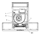
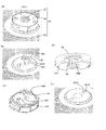
- FIG. 4 is a front view (A), a cross-sectional view (B), and (C) a cross-sectional view showing the position of the rotating body pressing stopper 3072 when the rotating body is removed, and a grease filter of the rotating body mounting device 30 according to the first embodiment.
- a conceptual diagram showing a positional relationship between the (rotating body) 301 and the mounting device insertion hole 3011 is shown.
- the rotating body mounting device 30 is an assembly of two constituent members, a grease filter (rotating body) 301 and a mounting device 302.
- the rotating body attachment / detachment mechanism 307 is composed of a rotating body attachment / detachment mechanism operation unit 3071 of the attachment device and a rotating body pressing stopper 3072, and is a grease filter (rotating body) 301 which is a constituent member of the rotating body attaching device 30 for cleaning or the like. Is removed from the mounting device 302 by pressing the rotating body attachment / detachment mechanism operation unit 3071 of the mounting device.
- FIG. 4C In the state of FIG. 4B showing the state before pressing the rotating body attachment / detachment mechanism operation unit 3071 of the mounting device, when the rotating body attachment / detachment mechanism operation unit 3071 of the mounting device is pressed, it rotates as shown in FIG. 4C.
- the body pressing stopper 3072 is configured to move into the mounting device 302 and completely fit within the mounting device 302.
- the moving mechanism of the rotating body pressing stopper 3072 is not shown, the rotating body attaching / detaching mechanism operation unit 3071 of the mounting device and the rotating body pressing stopper 3072 are connected by a link mechanism, or the rotating body attaching / detaching mechanism of the mounting device.
- the type of the moving mechanism is not limited, such as one in which an electromagnetic relay that operates based on the operation of the operating unit 3071 is provided and the rotating body pressing stopper 3072 moves.
- the center of the grease filter (rotating body) 301 is as shown in FIG. 4 (C).
- the mounting device 302 is pulled out from the mounting device insertion hole 3011 provided in the above.
- the grease filter (rotating body) 301 may be attached to the attachment device 302 in the reverse order.
- the power shaft 20 is inserted into the mounting device 302 from the power shaft insertion hole 305 side of FIG. 4A, and the mounting device 302 is inserted into the mounting device 302 with reference to the grease filter (rotating body) 301.
- the power shaft attachment / detachment mechanism operation unit 303 of the attachment device for attaching / detaching the attachment device 302 to / from the power shaft 20 is provided on the side where the attachment device 302 is not inserted.
- the power shaft attachment / detachment mechanism operation unit 303 of the attachment device is located at such a position, it can be easily reached from the lower side of the range hood 1 as shown in FIG. Even in the range hood 1 in which the power shaft 20 is provided horizontally, the power shaft attachment / detachment mechanism operation unit 303 of the mounting device can be easily reached.
- the mounting device 302 has a rotating body attachment / detachment mechanism operation unit 3071 of the mounting device on the side where the power shaft 20 is inserted into the mounting device 302 with reference to the grease filter (rotating body) 301. If the rotating body attachment / detachment mechanism operation unit 3071 of the mounting device is located at such a position, the grease filter (rotating body) 301 cannot be removed from the mounting device 302 until after the rotating body mounting device 30 has been removed from the power shaft 20. .. As can be seen from FIG.
- the rotating body attachment / detachment mechanism operation unit 3071 of the mounting device is located in a position where it cannot be seen and reached from under the range hood 1, and the operator mistakenly operates the rotating body attachment / detachment mechanism operation unit of the mounting device.
- the 3071 cannot be operated.
- the reason why the grease filter (rotating body) 301 can be removed from the mounting device 302 is that the grease filter (rotating body) 301 can be easily cleaned by removing it. Further, when the disposable type grease filter (rotating body) 301 is used when it becomes dirty, it can be easily replaced because there is a rotating body attachment / detachment mechanism operation unit 3071 of the mounting device.
- the rotating body has been described as a grease filter (rotating body) 301, but it may be used for a fan used in the range hood 1.
- the present invention is a general-purpose technique that can be used in a rotating body other than a range hood. The same applies to the following examples.
- the bell mouth (oil collecting member) 5 illustrated in FIGS. 1 and 3 (B) has an annular groove so that oil flying by centrifugal force can be collected from the grease filter (rotating body) 301. It also functions as a grease collecting member. The accumulated oil can be easily disposed of by simply removing the bell mouth (oil collecting member) 5.
- an oil collecting member for collecting oil flying from the fan by centrifugal force may be provided.
- an oil collecting member for collecting oil dripping from the casing of the fan or the like may be provided. The shape and installation position of the oil collecting member can be changed as appropriate depending on which member the oil drips from and the position where the oil drips.
- the oil collecting member is not limited to the bell mouth (oil collecting member) 5, and various members are included in the present invention. Further, a discharge pipe for discharging oil may be provided in the oil collecting member. In any case, in an environment where the oil adheres to the rotating body, the oil can be easily treated by providing the oil collecting member.
- the second embodiment is an embodiment in which the grease filter (rotating body) 301 used for the range hood 1 is used as a rotating body.
- the difference from the first embodiment is that the attachment device 302 can be further separated into the attachment / detachment device 40 and the rotating body holding device 50.
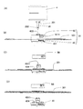
- 5A and 5B show a front view of (A) a grease filter drive motor (power device) 4 according to a second embodiment, (B) a front view of a rotating body mounting device 30, and (C) a rotating body holder of the rotating body mounting device 30.
- An exploded front view with the device 50 removed, and (D) an exploded front view with the rotating body holding device 50 and the grease filter (rotating body) 301 removed from the rotating body mounting device 30 are shown.
- FIG. 5A shows the first and second power shaft holding levers (403, 404), which are constituent members of the power shaft attachment / detachment mechanism, as described in “1 Attachment / detachment device A power shaft attachment / detachment mechanism” described later.
- the reduced diameter portion 202 of the held power shaft 20 is shown.
- the power shaft 20 is inserted through the boss cylinder power shaft insertion hole 433 shown in FIG. 5B, and the rotating body mounting device 30 is mounted on the power shaft 20.
- the rotating body mounting device 30 (rotating body holding device 50) can be operated by operating the power shaft attachment / detachment mechanism operation unit 401 of the attachment / detachment device of FIG. 5 (B).
- a grease filter (rotating body) 301 and three members of the attachment / detachment device 40) are integrated and can be removed from the power shaft 20.
- the grease filter (rotating body) 301 is pressed by operating the rotating body attachment / detachment mechanism operation unit 5011 of the rotating body holding device.
- the rotating body holding device 50 is removed, and the grease filter (rotating body) 301 can be removed.
- the rotating body attachment / detachment mechanism operation unit 5011 of the rotating body holding device is provided on the side where the power shaft 20 is inserted into the rotating body mounting device 30 with reference to the grease filter (rotating body) 301.
- the grease filter (rotating body) 301 can be attached to and detached from the rotating body mounting device 30.
- the grease filter (rotating body) 301 becomes an obstacle and the rotating body attachment / detachment mechanism operation unit 5011 of the rotating body holding device cannot be operated. It is the same as Example 1.
- the power shaft attachment / detachment mechanism operation unit 401 of the attachment / detachment device is provided in the attachment / detachment device 40, and when this is operated, the entire rotating body mounting device 30 is separated from the power shaft 20, and the grease filter (rotating body) 301 and the attachment / detachment device are removed.
- the three members of the 40 and the rotating body holding device 50 can be removed as a unit.
- the power shaft attachment / detachment mechanism operation unit 401 of the attachment / detachment device is arranged so as to be visible to the operator by simply removing the straightening vane from the range hood 1. It is configured for easy operation.
- FIG. 6 is an exploded view (A) and a front view of (B) a boss member 43 of the attachment / detachment device 40 according to the second embodiment.
- the attachment / detachment device 40 includes a power shaft attachment / detachment mechanism including a first power shaft holding lever 403, a second power shaft holding lever 404, and a power shaft holding lever urging member 402.
- the first power shaft holding lever 403 and the second power shaft holding lever 404 each include a power shaft attachment / detachment mechanism operation unit 401, a holding lever power shaft insertion hole 405, and a power shaft contact holding portion 407 of the attachment / detachment device. .. See FIG. 6 (A).
- the support cover 42 is housed in the attachment / detachment device lower cover 41.
- a first power shaft holding lever 403 and a second power shaft holding lever 404 are slidably provided on the support cover 42.
- the first power shaft holding lever 403 and the second power shaft holding lever 404 are provided with an urging member contact portion 406 so that one end of the power shaft holding lever urging member 402 comes into contact with the first power shaft holding lever 403 and the second power shaft holding lever 404.
- the other end of the power shaft holding lever urging member 402 is in contact with the boss member 43 (see FIG. 7).
- the power shaft holding lever urging member 402 urges the first and second power shaft holding levers (403, 404) in the direction of the arrow in FIG. 6, and the power shaft attachment / detachment mechanism operation unit 401 of the attachment / detachment device is used. , Is urged to go out of the boss member 43.
- FIG. 7 is a bottom perspective view of the boss member showing the contact relationship between the power shaft 20 and the first power shaft holding lever 403 according to the second embodiment, and the first power shaft holding lever 403 is the reduced diameter of the power shaft 20.
- the state of holding the part 202 is illustrated.
- the second power shaft holding lever 404 is not shown.
- the first and second power shaft holding levers (403, 404) hold the reduced diameter portion 202 of the power shaft 20 by the power shaft holding lever urging member 402. Refer to FIG. 5A for the shape of the reduced diameter portion 202 of the power shaft 20.
- the first power shaft holding lever 403 is attached by the power shaft holding lever urging member 402 (hidden behind the first power shaft holding lever 403 and not shown) in the direction of the arrow shown. It can be seen that the power shaft contact holding portion 407 is in contact with the reduced diameter portion 202 of the power shaft 20 and is held. The same applies to the second power shaft holding lever 404.
- the rotating body mounting device 30 is attached to the power shaft 20
- the reduced diameter portion 202 of the power shaft 20 is held from both sides by the first and second power shaft holding levers (403, 404).
- a coil spring can be mentioned as an example of the power shaft holding lever urging member 402, but any elastic body such as a leaf spring or rubber may be used as long as it has the same function.
- the power shaft 20 is inserted into the boss cylinder power shaft insertion hole 433 of the boss member 43, and then the holding lever power shaft insertion holes 405 of the first and second power shaft holding levers (403, 404).
- the support cover is inserted through the power shaft insertion hole 421 to the power shaft tip contact portion 411 provided at the center of the attachment / detachment device lower cover 41.
- the reduced diameter portion 202 of the power shaft 20 is designed to be exactly positioned at a position where the first and second power shaft holding levers (403 and 404) are located.
- the power shaft attachment / detachment mechanism operation unit 401 of the attachment / detachment device of the first and second power shaft holding levers (403, 404) is changed to the power shaft holding lever urging member 402. Push against the urging force. Then, the power shaft contact holding portion 407 of the first and second power shaft holding levers (403, 404) is separated from the reduced diameter portion 202 of the power shaft 20, and the rotating body mounting device 30 can be pulled out from the power shaft 20. ..
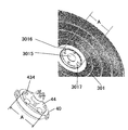
- FIG. 8 is a perspective view of the attachment / detachment device 40 and the grease filter (rotating body) 301 of the rotating body mounting device 30 according to the second embodiment.
- a protrusion (engaged mechanism) 434 is shown on the side of the boss member 43 facing the grease filter (rotating body) 301.
- the grease filter (rotating body) 301 is provided with a protrusion insertion hole (engagement mechanism) 3016, and is configured to insert a protrusion (engaged mechanism) 434 on the upper surface of the boss member 43. .. As a result, the grease filter (rotating body) 301 and the boss member 43 are firmly prevented from rotating.
- the engaging mechanism of the rotating body and the engaged mechanism of the attachment / detachment device may function as a rotation stopper, and the shape of the protrusion (engaged mechanism) 434 and the shape of the protrusion insertion hole (engagement mechanism) 3016 are various. it can.
- the protrusion (engaged mechanism) 434 shown in FIG. 5 (D) is assembled with the grease filter (rotating body) 301, the grease filter (rotation) is shown in FIG. 5 (C). Although it is configured to protrude from the opposite surface of the body) 301, it may be simply multiplied by the grease filter (rotating body) 301.
- a cap may be provided on the upper surface of the grease filter (rotating body) 301 as a cap (engagement mechanism) in which the protrusion (engaged mechanism) 434 fits exactly when mounted. Even in this way, it is firmly stopped.
- the protrusion (engaged mechanism) 434 is provided on the attachment / detachment device 40 side, but it may be provided on the rotating body pressing device 50 side, which will be described later, or both the attachment / detachment device 40 and the rotating body pressing device 50.
- a protrusion (engaged mechanism) may be provided.
- a protrusion (engaged mechanism) 434 is provided on the grease filter (rotating body) 301, and a protrusion (engaged) provided on the grease filter (rotating body) 301 is provided on the side of the attachment / detachment device 40 and / or the rotating body holding device 50.
- a housing portion (engagement mechanism) for accommodating the combined mechanism) 434 may be provided.
- FIG. 8 shows a convex portion 44 for attaching a grease filter on the upper surface of the attachment / detachment device.
- the grease filter (rotating body) 301 is provided with a recess 3017 for receiving the attachment / detachment device, which is a recess when viewed from the attachment / detachment device 40 side, on the mounting surface with the attachment / detachment device 40.
- the diameter A'of the grease filter mounting convex portion 44 is smaller than the diameter A of the attachment / detachment device receiving recess 3017, preferably substantially the same diameter, and both fit into each other.
- the grease filter (rotating body) 301 is provided with the attachment / detachment device receiving recess 3017, but it can also be implemented as the attachment / detachment device receiving convex portion.
- the attachment / detachment device 40 has the grease filter mounting recess. It will be provided.
- a convex portion or a concave portion for mounting the grease filter is provided on the surface of the rotating body pressing device 50 facing the grease filter (rotating body) 301, and this is a concave portion or a convex portion for receiving the rotating body pressing device of the grease filter (rotating body) 301. Even if it gets stuck, it is possible to achieve reverse reverse prevention.
- recesses and / or convex portions may be provided on both the attachment / detachment device 40 side and the rotating body holding device 50 side of the grease filter (rotating body) 301, and attachment / detachment may be provided so as to fit into the concave / / or convex portions.
- the device 40 and the rotating body holding device 50 are provided with recesses and / or protrusions.
- the concave and / or convex portions of the attachment / detachment device 40 and / or the rotating body holding device 50 which fit into the concave and / or convex portions of the grease filter (rotating body) 301, function as a front / rear reverse rotation prevention mechanism. It does not have to be exactly the same diameter.
- the attachment / detachment device 40 is configured so that the power shaft 20 is inserted into the boss cylinder power shaft insertion hole 433, and the attachment / detachment device 40 is driven by the tip of the attachment / detachment device 40.
- a plurality of pairs of pin receiving grooves 4311 are provided. Regardless of the circumferential direction in which the power shaft 20 is inserted into the boss cylinder power shaft insertion hole 433, the pair of drive pins 201 are configured to be fitted with the drive pin receiving groove 4311.
- the drive connecting portion is composed of the drive pin 201 and the drive pin receiving groove 4311.
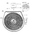
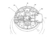
- FIG. 9 is an exploded view of the rotating body holding device 50 according to the second embodiment.
- the rotating body holding device case 502 is located on the most grease filter (rotating body) 301 side.
- a Rotating body attachment / detachment mechanism The rotating body attachment / detachment mechanism 501 is held by sandwiching the boss cylinder 431 (not shown) with a boss cylinder holding member (bar spring having a clamping action) 5012, which will be described in detail later.
- the rotating body attachment / detachment mechanism operation unit 5011 of the rotating body holding device is pushed into the opening 5013 of the boss cylinder holding member so as to cut into the boss cylinder holding member (bar spring having a clamping action) 5012. Opens, and the holding of the boss cylinder 431 is released.
- the boss cylinder 431 is a member protruding above the attachment / detachment device 40, and is a portion straddling the region indicated by the alternate long and short dash line in the front view of the boss member 43 in FIG. 6 (B).
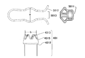
- FIG. 10A shows an enlarged view of the boss cylinder 431 according to the second embodiment.
- FIG. 10B is a perspective view showing a holding relationship between the boss cylinder 431 and the rotating body attachment / detachment mechanism 501 according to the second embodiment.
- a boss cylinder enlarged diameter portion 4315 is formed on the boss cylinder tip portion 4313 side of the boss cylinder 431, and a drive pin receiving groove 4311 is provided.
- a tapered surface 4312 is provided directly below the boss cylinder enlarged diameter portion 4315.
- boss cylinder holding member (bar spring having a clamping action) 5012 sandwiches the tapered surface 4312
- the urging force for sandwiching the boss cylinder holding member (bar spring having a clamping action) generates a component force on the tapered surface 4312 in the direction shown by the arrow in FIG. 10 (B).
- the boss cylinder 431 of the attachment / detachment device 40 is lifted, and the grease filter (rotating body) 301 sandwiched between the boss cylinder 431 and the rotating body holding device 50 acts as an urging portion for pressing the rotating body holding device 50.
- the grease filter (rotating body) 301 does not rattle, and noise and abnormal noise during rotation can be suppressed.
- the angle ⁇ of the tapered surface (see FIG. 10 (A)) suitable for performing the second function is 95 ° to 135 °.
- FIG. 11 is a conceptual diagram showing the relationship between the boss cylinder holding member (bar spring having a clamping action) 5012 and the boss cylinder tip portion 4313 according to the second embodiment.
- the support member 503 shown in FIG. 9 holds a boss cylinder holding member (bar spring having a clamping action) 5012 constituting the rotating body attaching / detaching mechanism 501 and a rotating body attaching / detaching mechanism operating unit 5011 of the rotating body holding device. It is a member that holds and holds the rotating body holding device case 502 so as not to come off.
- the rotating body holding device 50 is mounted by inserting the boss cylinder 431 of the attachment / detachment device 40 to which the grease filter (rotating body) 301 is attached from the boss cylinder inserting hole 5021 of the case of the rotating body holding device 50 shown in FIG. Ru.
- the boss cylinder tip 4313 When the boss cylinder tip 4313 is inserted through the boss cylinder insertion hole 5021 of the case, it first comes into contact with the boss cylinder holding member (bar spring having a clamping action) 5012. Next, when the boss cylinder tip portion 4313 is further pushed in, the boss cylinder tip portion 4313 passes through the boss cylinder insertion hole 5031 of the support member and slightly exits from the rotating body holding device 50 from the boss cylinder insertion hole 5041 of the upper cover. This state is as illustrated in FIG. 5 (B).
- the boss cylinder holding member (bar spring having a clamping action) 5012 is a bar spring having a circular cross section.
- the boss cylinder holding member (bar spring having a clamping action) 5012 is a bar spring having a circular cross section.
- the boss cylinder holding member (bar spring having a clamping action) 5012 has a circular cross section, and the circular boss cylinder holding member (bar spring having a clamping action) 5012 hits the curved surface of the tip portion 4313 of the boss cylinder and holds the rotating body as it is. By continuing to insert the boss cylinder 431 into the device 50, it is expanded and comes into contact with the boss cylinder enlarged diameter portion 4315.
- the rotating body attachment / detachment mechanism 501 has both the first function and the second function, but the rotating body attachment / detachment mechanism 501 originally has the first function. It is sufficient, and it is not necessary to have the second function at the same time. Further, a function (second function) as an urging portion for pressing the grease filter (rotating body) 301 may be provided by an urging portion provided separately from the rotating body attachment / detachment mechanism 501.
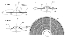
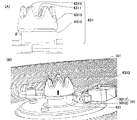
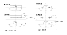
- FIG. 12 is a conceptual diagram showing various aspects of the urging unit according to the second embodiment.
- FIG. 12A is a cushion type. A cushion is provided on the lower surface of the rotating body pressing device 50, and when the rotating body pressing device 50 is attached, it functions as an urging portion for pressing the grease filter (rotating body) 301.
- FIG. 12B is a lever type, and a lever lifting protrusion is provided on the upper surface of the attachment / detachment device 40 to lift the power point of the lever provided on the rotating body holding device 50.
- the point of action on the opposite side of the fulcrum from the point of effort functions as an urging portion that presses the grease filter (rotating body) 301.
- the mode of the urging portion as described above is an example, and may be any one that functions as an urging portion, such as urging by a magnetic force using a magnet, and is limited to the above example. It's not a thing.
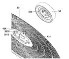
- FIG. 13 is an exploded view showing the mounting relationship of the attachment / detachment device 40, the grease filter (rotating body) 301, and the rotating body holding device 50 according to the second embodiment.
- the boss cylinder 431 protrudes from the attachment / detachment device insertion hole 3015 of the grease filter (rotating body) 301, and the protrusion (engaged) of the attachment / detachment device 40 comes out from the protrusion insertion hole (engagement mechanism) 3016 of the grease filter (rotary body) 301.
- Mechanism) 434 is popping out.
- An annular groove 505 that accommodates the protruding protrusion (engaged mechanism) 434 is provided on the surface of the rotating body holding device 50 on the grease filter (rotating body) 301 side.
- the annular groove 505 has an advantageous effect in that the protrusion (engaged mechanism) 434 can be accommodated regardless of the direction. However, if it is desired to firmly prevent the grease filter (rotating body) 301 from rotating, the rotating body holding device 50 may be provided with a recess in which the protrusion (engaged mechanism) 434 fits.
- the protrusion (engaged mechanism) 434 may be provided on the rotating body holding device 50, and in this case, the annular groove is formed on the mounting surface of the grease filter (rotating body) 301 of the attachment / detachment device 40. It will be provided.
- the protrusions (engaged mechanism) 434 provided on the attachment / detachment device 40 may be arranged with regularity such as arrangement on the same circumference, but may be arranged without regularity. In that case, when the grease filter (rotating body) 301 is attached to the attachment / detachment device 40, it is accommodated in correspondence with the arrangement of the protrusion (engaged mechanism) 434 protruding from the protrusion insertion hole (engagement mechanism) 3016.
- the arrangement of the annular groove 505 and the like on the bottom surface of the rotating body holding device 50 is determined. Further, the grease filter (rotating body) 301 may be provided with an engaging mechanism composed of protrusions, and the attachment / detachment device 40 and / or the rotating body holding device 50 may be provided with an annular groove for accommodating the protrusions or a recess for just accommodating the protrusions. As described above, various aspects are included in the present invention.
- the third embodiment is another aspect of the rotating body holding device 50 of the second embodiment.
- FIG. 14 is a perspective view of the rotating body holding device 50 according to the third embodiment, in which (A) a perspective view and (B) an upper cover 504 are removed.
- the rotating body attachment / detachment mechanism 501 of the third embodiment is similar to the structure of the power shaft attachment / detachment mechanism described in “1 attachment / detachment device A power shaft attachment / detachment mechanism” of the second embodiment. From the side of the rotating body holding device 50 according to the third embodiment illustrated in FIG. 14A, the rotating body attaching / detaching mechanism operation unit 5011 of the rotating body holding device protrudes, and the upper portion is covered with the upper cover 504.
- a boss cylinder insertion hole 5041 for the upper cover is provided in the central portion.
- the rotating body attachment / detachment mechanism 501 is the boss cylinder holding lever 506 of the rotating body holding device provided with the operation unit 5011 of the rotating body attachment / detachment mechanism. , It is composed of a lever spring 5062.
- the rotating body holding device 50 is provided with boss cylinder holding levers 506 of the two rotating body holding devices, and the boss cylinder holding levers 506 of the two rotating body holding devices are respectively provided with lever springs 5062. There is.
- the boss cylinder holding lever 506 of the two rotating body holding devices is urged as shown by an arrow, and the boss cylinder 431 (not shown) inserted into the boss cylinder insertion hole 5061 of the boss cylinder holding lever is inserted. Hold from both sides.
- the pinching position of the boss cylinder holding lever 506 of the two rotating body holding devices is a portion directly below the boss cylinder enlarged diameter portion 4315 shown in FIG. 10 (A), and the boss cylinder 431 is sandwiched at this position. , The attachment / detachment device 40 will not come off.
- the boss cylinder holding lever 506 of the rotating body holding device is held at the position of the tapered surface 4312 in FIG. 10 (A), and an urging force is applied in the direction indicated by the arrow in FIG. 10 (B) to hold the rotating body.
- the boss cylinder 431 is not provided with the tapered surface 4312, and the rotating body is separately pressed as described in "2 Rotating body holding device B Bending part for pressing the rotating body".
- An urging unit may be provided.
- an embodiment in which an urging portion for pressing the rotating body is not provided may be included.
- the fourth embodiment is another aspect of the rotating body holding device 50 of the second embodiment.
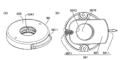
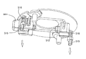
- FIG. 15 shows a perspective view (A) and a perspective view (B) of the rotating body holding device 50 according to the fourth embodiment with the upper cover 504 removed.
- the rotating body attaching / detaching mechanism operation unit 5011 of the rotating body pressing device protrudes from the rotating body pressing device 50.
- the rotating body attachment / detachment mechanism operation unit 5011 of the rotating body pressing device is configured to protrude from the side surface, but any portion that can be operated may be used, and in the present invention, the rotating body pressing device may be used. It may protrude from the top of the device 50.
- the rotating body attachment / detachment mechanism operation unit 5011 of the rotating body holding device can be operated, it is not necessary to pop out.
- other operation units such as the power shaft attachment / detachment mechanism operation unit of the mounting device.
- the rotating body attachment / detachment mechanism 501 is composed of a boss cylinder holding lever 507 provided with a rotating body attaching / detaching mechanism operation unit 5011 of the rotating body holding device and a pressing spring 5071 of the boss cylinder holding lever.
- the boss cylinder holding lever 507 is provided with a rotating body attachment / detachment mechanism operation unit 5011 of the rotating body holding device at one end, and a pressing spring 5071 of the boss cylinder holding lever is attached to the other end.
- the boss cylinder holding lever 507 is urged in the direction of the above, and at a position directly below the boss cylinder expanding portion 4315 (see FIG.
- the boss cylinder contact portion 5073 of the boss cylinder holding lever is the boss of the boss cylinder holding lever.
- the boss cylinder 431 inserted in the cylinder insertion hole 5072 is pressed.
- the boss cylinder 431 is held.
- the boss cylinder insertion hole 5072 of the boss cylinder holding lever is not a perfect circle but has a long diameter in the moving direction of the boss cylinder holding lever 507. If it is a perfect circle, the boss cylinder 431 can be pulled out only when the positions of the boss cylinder enlarged diameter portion 4315 and the boss cylinder insertion hole 5072 of the boss cylinder holding lever match, so the rotating body attachment / detachment mechanism operation unit 5011 of the rotating body holding device It becomes difficult to adjust the amount of movement.
- the rotating body holding device 50 can be removed from the attachment / detachment device 40 without strictly adjusting the pushing degree, and the grease filter (rotating body) 301 can be removed.
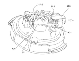
- 16A and 16B are a perspective view of (A) the rotating body mounting device 30 according to the fifth embodiment, (B) a perspective view with the rotating body holding device 50 removed, (C) a perspective view of the attachment / detachment device 40, and (D) a rotating body. It is a perspective view of the holding device 50 seen from the side of the grease filter (rotating body) 301, and (E) an enlarged perspective view of the grease filter (rotating body) 301. In FIG. 16A, the tip end portion 4313 of the boss cylinder of the attachment / detachment device 40 is visible.
- the rotating body mounting device 30 including the attachment / detachment device 40, the grease filter (rotating body) 301, and the rotating body holding device 50 is shown.
- FIG. 16B shows a state in which the rotating body holding device 50 is removed from the state shown in FIG. 16A.
- the grease filter (rotating body) 301 is provided with an engagement protrusion insertion hole (engagement mechanism) 3018 (FIG. 16 (E)), and is provided in the attachment / detachment device 40 as shown in FIG. 16 (B).
- a protrusion (engaged mechanism) 435 is inserted.
- the engaging projection (engaged mechanism) 435 has a shape in which the tip is bent toward the center of the grease filter (rotating body) 301 from the root.
- the engagement projection 435 is inserted into the engagement projection insertion portion 509 of the rotating body pressing device 50 shown in FIG. 16 (D), and then the rotating body pressing device 50 is rotated toward the engagement projection engagement portion 508 side to engage the engaging projection 435. , It is even more firmly stopped.
- FIG. 17 is a perspective view of the rotating body attaching / detaching mechanism 501 of the rotating body pressing device 50 according to the fifth embodiment, and is a grease filter (rotation) that must be originally mounted in this state.
- Body 301 is not shown for illustration.
- members unnecessary for explanation are omitted from the rotating body holding device 50 so that the inside of the rotating body holding device 50 can be seen.
- the shape of the boss cylinder 431 of the fifth embodiment is different from that of the second to fourth embodiments, and is cylindrical without the boss cylinder enlarged diameter portion 4315. Further, the boss cylinder 431 is provided with a fitting groove 436 on the side surface. The shape of the fitting groove 436 is shown in FIG.
- the attachment / detachment protrusion 512 is connected to the rotating body attachment / detachment mechanism operation unit 5011 of the rotating body holding device by the link mechanism 511.
- the rotating body attachment / detachment mechanism operation unit 5011 of the rotating body holding device is provided with a attachment / detachment protrusion urging spring 513 that urges the rotor in the direction of the arrow in the drawing.
- Example 2 Biasing part for pressing the rotating body
- the boss cylinder holding member (bar spring having a clamping action) 5012 sandwiches the tapered surface 4312, so that the urging force for sandwiching the boss cylinder holding member (bar spring) 5012.
- a component force is generated on the tapered surface 4312, and the urging portion is configured so as to sandwich the grease filter (rotating body) 301 with the attachment / detachment device 40 in the direction shown by the arrow.
- Example 5 unlike that, an urging portion for pressing the grease filter (rotating body) 301 was configured by providing the backlash prevention protrusion 515.
- the backlash prevention protrusion 515 is provided on the surface of the rotating body holding device 50 on the grease filter (rotating body) 301 side.
- FIG. 18 is a perspective view of a state in which a member unnecessary for the explanation of the rotating body holding device 50 according to the fifth embodiment is removed, and the backlash prevention protrusion 515 is arranged via the backlash prevention protrusion urging spring 516 and the arrow indicates. Being urged in the direction.
- the backlash prevention protrusion 515 functions as an urging portion that presses the grease filter (rotating body) 301.
- the grease filter (rotating body) 301 sandwiched between the attachment / detachment device 40 and the rotating body holding device 50 is prevented from rattling.
- the rotating body has been described as a grease filter (rotating body) 301, but it may be used for a fan used in a range hood. Further, the present invention is a general-purpose technique that can be used in a rotating body other than a range hood.
- the rotating body mounting device including the rotating body and the mounting device can be integrally attached to and detached from the power shaft, and especially when the rotating body is located at a high place such as a range hood, the removal work can be performed. Installation work has become easier. Further, since the rotating body attachment / detachment mechanism operation unit for attaching / detaching the rotating body from the rotating body mounting device is provided on the side where the power shaft which is normally out of reach is inserted, the rotating body attachment / detachment mechanism operation unit is mistakenly operated to rotate. It is avoided that the body disassembles and falls.
Landscapes
- Engineering & Computer Science (AREA)
- General Engineering & Computer Science (AREA)
- Mechanical Engineering (AREA)
- Chemical & Material Sciences (AREA)
- Combustion & Propulsion (AREA)
- Structures Of Non-Positive Displacement Pumps (AREA)
- Ventilation (AREA)
- Filtering Of Dispersed Particles In Gases (AREA)
- Snaps, Bayonet Connections, Set Pins, And Snap Rings (AREA)
Priority Applications (2)
| Application Number | Priority Date | Filing Date | Title |
|---|---|---|---|
| SG11202112810YA SG11202112810YA (en) | 2019-06-19 | 2020-04-30 | Rotary body mounting device, oil collection device, and range hood |
| MYPI2021007271A MY209981A (en) | 2019-06-19 | 2020-04-30 | Rotary body mounting device, oil collection device, and range hood |
Applications Claiming Priority (2)
| Application Number | Priority Date | Filing Date | Title |
|---|---|---|---|
| JP2019113992A JP7033324B2 (ja) | 2019-06-19 | 2019-06-19 | 回転体装着装置、油捕集装置及びレンジフード |
| JP2019-113992 | 2019-06-19 |
Publications (1)
| Publication Number | Publication Date |
|---|---|
| WO2020255568A1 true WO2020255568A1 (ja) | 2020-12-24 |
Family
ID=73799273
Family Applications (1)
| Application Number | Title | Priority Date | Filing Date |
|---|---|---|---|
| PCT/JP2020/018239 Ceased WO2020255568A1 (ja) | 2019-06-19 | 2020-04-30 | 回転体装着装置、油捕集装置及びレンジフード |
Country Status (6)
| Country | Link |
|---|---|
| JP (2) | JP7033324B2 (enExample) |
| CN (1) | CN112113250B (enExample) |
| MY (1) | MY209981A (enExample) |
| SG (1) | SG11202112810YA (enExample) |
| TW (1) | TWI858081B (enExample) |
| WO (1) | WO2020255568A1 (enExample) |
Citations (6)
| Publication number | Priority date | Publication date | Assignee | Title |
|---|---|---|---|---|
| JP2011257106A (ja) * | 2010-06-11 | 2011-12-22 | Fuji Industrial Co Ltd | 送風機 |
| JP2014214889A (ja) * | 2013-04-22 | 2014-11-17 | 富士工業株式会社 | 着脱構造およびレンジフード |
| JP2014240740A (ja) * | 2013-06-12 | 2014-12-25 | 富士工業株式会社 | 着脱構造およびレンジフード |
| JP2015169393A (ja) * | 2014-03-07 | 2015-09-28 | パナソニックIpマネジメント株式会社 | 排気羽根固定用スピンナー及びこれを用いたレンジフード |
| JP2016040493A (ja) * | 2014-08-12 | 2016-03-24 | 株式会社ハーマン | レンジフード |
| CN108800258A (zh) * | 2018-08-07 | 2018-11-13 | 珠海格力电器股份有限公司 | 一种油烟分离网与驱动装置的连接结构及油烟机 |
Family Cites Families (10)
| Publication number | Priority date | Publication date | Assignee | Title |
|---|---|---|---|---|
| JPS55132396U (enExample) * | 1979-03-12 | 1980-09-19 | ||
| JPH10132352A (ja) * | 1996-10-31 | 1998-05-22 | Fuji Kogyo Corp | 排気装置に対するフィルタの取り付け構造 |
| JP2000205622A (ja) | 1999-01-13 | 2000-07-28 | Hitachi Chem Co Ltd | キッチンフ―ドおよびキッチンフ―ド用フィルタ― |
| JP3133960U (ja) * | 2007-01-24 | 2007-08-02 | 有限会社エムウェイ | 不織布空調用フィルター取付金具類及び押さえ金枠 |
| CN201322349Y (zh) * | 2008-04-29 | 2009-10-07 | 徐贵阳 | 离心净化式抽油烟机 |
| JP5332299B2 (ja) * | 2008-05-12 | 2013-11-06 | パナソニック株式会社 | 羽根車の着脱装置 |
| CN203657030U (zh) * | 2013-11-01 | 2014-06-18 | 关建新 | 一种带油烟机分离网的新型油烟机 |
| TW201530064A (zh) * | 2014-01-28 | 2015-08-01 | jing-zhong Chen | 小型油霧分離機的裝置 |
| JP2018066329A (ja) * | 2016-10-20 | 2018-04-26 | 日立ジョンソンコントロールズ空調株式会社 | 空調用ファン、および、それを用いた空気調和機 |
| CN109595630B (zh) * | 2017-09-30 | 2024-02-20 | 宁波方太厨具有限公司 | 一种吸油烟机 |
-
2019
- 2019-06-19 JP JP2019113992A patent/JP7033324B2/ja active Active
-
2020
- 2020-04-30 SG SG11202112810YA patent/SG11202112810YA/en unknown
- 2020-04-30 MY MYPI2021007271A patent/MY209981A/en unknown
- 2020-04-30 WO PCT/JP2020/018239 patent/WO2020255568A1/ja not_active Ceased
- 2020-06-12 CN CN202010534224.6A patent/CN112113250B/zh active Active
- 2020-06-16 TW TW109120288A patent/TWI858081B/zh active
-
2021
- 2021-08-26 JP JP2021137707A patent/JP7248335B2/ja active Active
Patent Citations (6)
| Publication number | Priority date | Publication date | Assignee | Title |
|---|---|---|---|---|
| JP2011257106A (ja) * | 2010-06-11 | 2011-12-22 | Fuji Industrial Co Ltd | 送風機 |
| JP2014214889A (ja) * | 2013-04-22 | 2014-11-17 | 富士工業株式会社 | 着脱構造およびレンジフード |
| JP2014240740A (ja) * | 2013-06-12 | 2014-12-25 | 富士工業株式会社 | 着脱構造およびレンジフード |
| JP2015169393A (ja) * | 2014-03-07 | 2015-09-28 | パナソニックIpマネジメント株式会社 | 排気羽根固定用スピンナー及びこれを用いたレンジフード |
| JP2016040493A (ja) * | 2014-08-12 | 2016-03-24 | 株式会社ハーマン | レンジフード |
| CN108800258A (zh) * | 2018-08-07 | 2018-11-13 | 珠海格力电器股份有限公司 | 一种油烟分离网与驱动装置的连接结构及油烟机 |
Also Published As
| Publication number | Publication date |
|---|---|
| CN112113250B (zh) | 2024-11-22 |
| JP2021001698A (ja) | 2021-01-07 |
| JP7033324B2 (ja) | 2022-03-10 |
| TWI858081B (zh) | 2024-10-11 |
| CN112113250A (zh) | 2020-12-22 |
| MY209981A (en) | 2025-08-19 |
| SG11202112810YA (en) | 2021-12-30 |
| JP2021193330A (ja) | 2021-12-23 |
| JP7248335B2 (ja) | 2023-03-29 |
| TW202104803A (zh) | 2021-02-01 |
Similar Documents
| Publication | Publication Date | Title |
|---|---|---|
| CN107360726B (zh) | 空调的室内机 | |
| JP4757730B2 (ja) | 空気調和機 | |
| JP6236228B2 (ja) | 着脱構造およびレンジフード | |
| CN110822523B (zh) | 过滤组件和油烟净化装置 | |
| JP2021504072A (ja) | 結合構造を有する毛切断ユニット | |
| JP7033324B2 (ja) | 回転体装着装置、油捕集装置及びレンジフード | |
| JP2022050409A (ja) | 回転体装着装置、油捕集装置及びレンジフード | |
| JP5470165B2 (ja) | 送風機 | |
| JP5298371B2 (ja) | ファン装置 | |
| JP2009509090A (ja) | ファンのための取外し可能なインペラ | |
| JP5588848B2 (ja) | 送風装置 | |
| HK40040593B (zh) | 旋转体安装装置、油捕集装置以及抽油烟机 | |
| CN217713096U (zh) | 风扇安装座、风扇组件和空气炸锅 | |
| CN110755947A (zh) | 油烟净化装置 | |
| HK40040593A (en) | Rotary body mounting device, oil collection device, and range hood | |
| JP2010156253A (ja) | ファン装置 | |
| JP7294632B2 (ja) | 着脱装置及びレンジフード | |
| KR101961492B1 (ko) | 압축기용 풀리-허브 조립체 | |
| JP2011220630A (ja) | 換気装置 | |
| CN222210463U (zh) | 一种具有断电保护功能的吸油烟机 | |
| CN112240303A (zh) | 送风装置、空气调节机 | |
| JP2009236046A (ja) | 電動送風機及び電気掃除機 | |
| CN111503681B (zh) | 净化装置 | |
| US20030013390A1 (en) | Electrical knife sharpening device | |
| JP2020190359A (ja) | ワンウェイクラッチを用いた動力伝達構造 |
Legal Events
| Date | Code | Title | Description |
|---|---|---|---|
| 121 | Ep: the epo has been informed by wipo that ep was designated in this application |
Ref document number: 20825451 Country of ref document: EP Kind code of ref document: A1 |
|
| NENP | Non-entry into the national phase |
Ref country code: DE |
|
| 122 | Ep: pct application non-entry in european phase |
Ref document number: 20825451 Country of ref document: EP Kind code of ref document: A1 |
|
| WWG | Wipo information: grant in national office |
Ref document number: 11202112810Y Country of ref document: SG |
|
| WWP | Wipo information: published in national office |
Ref document number: 11202112810Y Country of ref document: SG |