WO2020250646A1 - ガラスロールの製造方法 - Google Patents
ガラスロールの製造方法 Download PDFInfo
- Publication number
- WO2020250646A1 WO2020250646A1 PCT/JP2020/020395 JP2020020395W WO2020250646A1 WO 2020250646 A1 WO2020250646 A1 WO 2020250646A1 JP 2020020395 W JP2020020395 W JP 2020020395W WO 2020250646 A1 WO2020250646 A1 WO 2020250646A1
- Authority
- WO
- WIPO (PCT)
- Prior art keywords
- film
- glass
- film forming
- forming apparatus
- temperature
- Prior art date
- Legal status (The legal status is an assumption and is not a legal conclusion. Google has not performed a legal analysis and makes no representation as to the accuracy of the status listed.)
- Ceased
Links
Images



Classifications
-
- C—CHEMISTRY; METALLURGY
- C03—GLASS; MINERAL OR SLAG WOOL
- C03C—CHEMICAL COMPOSITION OF GLASSES, GLAZES OR VITREOUS ENAMELS; SURFACE TREATMENT OF GLASS; SURFACE TREATMENT OF FIBRES OR FILAMENTS MADE FROM GLASS, MINERALS OR SLAGS; JOINING GLASS TO GLASS OR OTHER MATERIALS
- C03C17/00—Surface treatment of glass, not in the form of fibres or filaments, by coating
- C03C17/28—Surface treatment of glass, not in the form of fibres or filaments, by coating with organic material
- C03C17/32—Surface treatment of glass, not in the form of fibres or filaments, by coating with organic material with synthetic or natural resins
-
- B—PERFORMING OPERATIONS; TRANSPORTING
- B65—CONVEYING; PACKING; STORING; HANDLING THIN OR FILAMENTARY MATERIAL
- B65H—HANDLING THIN OR FILAMENTARY MATERIAL, e.g. SHEETS, WEBS, CABLES
- B65H18/00—Winding webs
- B65H18/08—Web-winding mechanisms
- B65H18/10—Mechanisms in which power is applied to web-roll spindle
- B65H18/103—Reel-to-reel type web winding and unwinding mechanisms
-
- B—PERFORMING OPERATIONS; TRANSPORTING
- B65—CONVEYING; PACKING; STORING; HANDLING THIN OR FILAMENTARY MATERIAL
- B65H—HANDLING THIN OR FILAMENTARY MATERIAL, e.g. SHEETS, WEBS, CABLES
- B65H20/00—Advancing webs
- B65H20/02—Advancing webs by friction roller
-
- B—PERFORMING OPERATIONS; TRANSPORTING
- B65—CONVEYING; PACKING; STORING; HANDLING THIN OR FILAMENTARY MATERIAL
- B65H—HANDLING THIN OR FILAMENTARY MATERIAL, e.g. SHEETS, WEBS, CABLES
- B65H23/00—Registering, tensioning, smoothing or guiding webs
- B65H23/04—Registering, tensioning, smoothing or guiding webs longitudinally
- B65H23/18—Registering, tensioning, smoothing or guiding webs longitudinally by controlling or regulating the web-advancing mechanism, e.g. mechanism acting on the running web
-
- B—PERFORMING OPERATIONS; TRANSPORTING
- B65—CONVEYING; PACKING; STORING; HANDLING THIN OR FILAMENTARY MATERIAL
- B65H—HANDLING THIN OR FILAMENTARY MATERIAL, e.g. SHEETS, WEBS, CABLES
- B65H7/00—Controlling article feeding, separating, pile-advancing, or associated apparatus, to take account of incorrect feeding, absence of articles, or presence of faulty articles
- B65H7/20—Controlling associated apparatus
-
- C—CHEMISTRY; METALLURGY
- C03—GLASS; MINERAL OR SLAG WOOL
- C03C—CHEMICAL COMPOSITION OF GLASSES, GLAZES OR VITREOUS ENAMELS; SURFACE TREATMENT OF GLASS; SURFACE TREATMENT OF FIBRES OR FILAMENTS MADE FROM GLASS, MINERALS OR SLAGS; JOINING GLASS TO GLASS OR OTHER MATERIALS
- C03C17/00—Surface treatment of glass, not in the form of fibres or filaments, by coating
- C03C17/22—Surface treatment of glass, not in the form of fibres or filaments, by coating with other inorganic material
- C03C17/23—Oxides
- C03C17/245—Oxides by deposition from the vapour phase
-
- C—CHEMISTRY; METALLURGY
- C23—COATING METALLIC MATERIAL; COATING MATERIAL WITH METALLIC MATERIAL; CHEMICAL SURFACE TREATMENT; DIFFUSION TREATMENT OF METALLIC MATERIAL; COATING BY VACUUM EVAPORATION, BY SPUTTERING, BY ION IMPLANTATION OR BY CHEMICAL VAPOUR DEPOSITION, IN GENERAL; INHIBITING CORROSION OF METALLIC MATERIAL OR INCRUSTATION IN GENERAL
- C23C—COATING METALLIC MATERIAL; COATING MATERIAL WITH METALLIC MATERIAL; SURFACE TREATMENT OF METALLIC MATERIAL BY DIFFUSION INTO THE SURFACE, BY CHEMICAL CONVERSION OR SUBSTITUTION; COATING BY VACUUM EVAPORATION, BY SPUTTERING, BY ION IMPLANTATION OR BY CHEMICAL VAPOUR DEPOSITION, IN GENERAL
- C23C14/00—Coating by vacuum evaporation, by sputtering or by ion implantation of the coating forming material
- C23C14/02—Pretreatment of the material to be coated
-
- C—CHEMISTRY; METALLURGY
- C23—COATING METALLIC MATERIAL; COATING MATERIAL WITH METALLIC MATERIAL; CHEMICAL SURFACE TREATMENT; DIFFUSION TREATMENT OF METALLIC MATERIAL; COATING BY VACUUM EVAPORATION, BY SPUTTERING, BY ION IMPLANTATION OR BY CHEMICAL VAPOUR DEPOSITION, IN GENERAL; INHIBITING CORROSION OF METALLIC MATERIAL OR INCRUSTATION IN GENERAL
- C23C—COATING METALLIC MATERIAL; COATING MATERIAL WITH METALLIC MATERIAL; SURFACE TREATMENT OF METALLIC MATERIAL BY DIFFUSION INTO THE SURFACE, BY CHEMICAL CONVERSION OR SUBSTITUTION; COATING BY VACUUM EVAPORATION, BY SPUTTERING, BY ION IMPLANTATION OR BY CHEMICAL VAPOUR DEPOSITION, IN GENERAL
- C23C14/00—Coating by vacuum evaporation, by sputtering or by ion implantation of the coating forming material
- C23C14/22—Coating by vacuum evaporation, by sputtering or by ion implantation of the coating forming material characterised by the process of coating
- C23C14/34—Sputtering
-
- C—CHEMISTRY; METALLURGY
- C23—COATING METALLIC MATERIAL; COATING MATERIAL WITH METALLIC MATERIAL; CHEMICAL SURFACE TREATMENT; DIFFUSION TREATMENT OF METALLIC MATERIAL; COATING BY VACUUM EVAPORATION, BY SPUTTERING, BY ION IMPLANTATION OR BY CHEMICAL VAPOUR DEPOSITION, IN GENERAL; INHIBITING CORROSION OF METALLIC MATERIAL OR INCRUSTATION IN GENERAL
- C23C—COATING METALLIC MATERIAL; COATING MATERIAL WITH METALLIC MATERIAL; SURFACE TREATMENT OF METALLIC MATERIAL BY DIFFUSION INTO THE SURFACE, BY CHEMICAL CONVERSION OR SUBSTITUTION; COATING BY VACUUM EVAPORATION, BY SPUTTERING, BY ION IMPLANTATION OR BY CHEMICAL VAPOUR DEPOSITION, IN GENERAL
- C23C14/00—Coating by vacuum evaporation, by sputtering or by ion implantation of the coating forming material
- C23C14/22—Coating by vacuum evaporation, by sputtering or by ion implantation of the coating forming material characterised by the process of coating
- C23C14/56—Apparatus specially adapted for continuous coating; Arrangements for maintaining the vacuum, e.g. vacuum locks
-
- C—CHEMISTRY; METALLURGY
- C23—COATING METALLIC MATERIAL; COATING MATERIAL WITH METALLIC MATERIAL; CHEMICAL SURFACE TREATMENT; DIFFUSION TREATMENT OF METALLIC MATERIAL; COATING BY VACUUM EVAPORATION, BY SPUTTERING, BY ION IMPLANTATION OR BY CHEMICAL VAPOUR DEPOSITION, IN GENERAL; INHIBITING CORROSION OF METALLIC MATERIAL OR INCRUSTATION IN GENERAL
- C23C—COATING METALLIC MATERIAL; COATING MATERIAL WITH METALLIC MATERIAL; SURFACE TREATMENT OF METALLIC MATERIAL BY DIFFUSION INTO THE SURFACE, BY CHEMICAL CONVERSION OR SUBSTITUTION; COATING BY VACUUM EVAPORATION, BY SPUTTERING, BY ION IMPLANTATION OR BY CHEMICAL VAPOUR DEPOSITION, IN GENERAL
- C23C14/00—Coating by vacuum evaporation, by sputtering or by ion implantation of the coating forming material
- C23C14/22—Coating by vacuum evaporation, by sputtering or by ion implantation of the coating forming material characterised by the process of coating
- C23C14/56—Apparatus specially adapted for continuous coating; Arrangements for maintaining the vacuum, e.g. vacuum locks
- C23C14/562—Apparatus specially adapted for continuous coating; Arrangements for maintaining the vacuum, e.g. vacuum locks for coating elongated substrates
-
- B—PERFORMING OPERATIONS; TRANSPORTING
- B65—CONVEYING; PACKING; STORING; HANDLING THIN OR FILAMENTARY MATERIAL
- B65H—HANDLING THIN OR FILAMENTARY MATERIAL, e.g. SHEETS, WEBS, CABLES
- B65H2301/00—Handling processes for sheets or webs
- B65H2301/50—Auxiliary process performed during handling process
- B65H2301/51—Modifying a characteristic of handled material
- B65H2301/514—Modifying physical properties
- B65H2301/5143—Warming
-
- B—PERFORMING OPERATIONS; TRANSPORTING
- B65—CONVEYING; PACKING; STORING; HANDLING THIN OR FILAMENTARY MATERIAL
- B65H—HANDLING THIN OR FILAMENTARY MATERIAL, e.g. SHEETS, WEBS, CABLES
- B65H2301/00—Handling processes for sheets or webs
- B65H2301/50—Auxiliary process performed during handling process
- B65H2301/52—Auxiliary process performed during handling process for starting
- B65H2301/522—Threading web into machine
-
- B—PERFORMING OPERATIONS; TRANSPORTING
- B65—CONVEYING; PACKING; STORING; HANDLING THIN OR FILAMENTARY MATERIAL
- B65H—HANDLING THIN OR FILAMENTARY MATERIAL, e.g. SHEETS, WEBS, CABLES
- B65H2406/00—Means using fluid
- B65H2406/30—Suction means
- B65H2406/31—Suction box; Suction chambers
- B65H2406/311—Suction box; Suction chambers for accumulating a loop of handled material
-
- B—PERFORMING OPERATIONS; TRANSPORTING
- B65—CONVEYING; PACKING; STORING; HANDLING THIN OR FILAMENTARY MATERIAL
- B65H—HANDLING THIN OR FILAMENTARY MATERIAL, e.g. SHEETS, WEBS, CABLES
- B65H2513/00—Dynamic entities; Timing aspects
- B65H2513/10—Speed
-
- B—PERFORMING OPERATIONS; TRANSPORTING
- B65—CONVEYING; PACKING; STORING; HANDLING THIN OR FILAMENTARY MATERIAL
- B65H—HANDLING THIN OR FILAMENTARY MATERIAL, e.g. SHEETS, WEBS, CABLES
- B65H2701/00—Handled material; Storage means
- B65H2701/10—Handled articles or webs
- B65H2701/17—Nature of material
-
- C—CHEMISTRY; METALLURGY
- C03—GLASS; MINERAL OR SLAG WOOL
- C03C—CHEMICAL COMPOSITION OF GLASSES, GLAZES OR VITREOUS ENAMELS; SURFACE TREATMENT OF GLASS; SURFACE TREATMENT OF FIBRES OR FILAMENTS MADE FROM GLASS, MINERALS OR SLAGS; JOINING GLASS TO GLASS OR OTHER MATERIALS
- C03C2217/00—Coatings on glass
- C03C2217/90—Other aspects of coatings
- C03C2217/94—Transparent conductive oxide layers [TCO] being part of a multilayer coating
- C03C2217/948—Layers comprising indium tin oxide [ITO]
-
- C—CHEMISTRY; METALLURGY
- C03—GLASS; MINERAL OR SLAG WOOL
- C03C—CHEMICAL COMPOSITION OF GLASSES, GLAZES OR VITREOUS ENAMELS; SURFACE TREATMENT OF GLASS; SURFACE TREATMENT OF FIBRES OR FILAMENTS MADE FROM GLASS, MINERALS OR SLAGS; JOINING GLASS TO GLASS OR OTHER MATERIALS
- C03C2218/00—Methods for coating glass
- C03C2218/10—Deposition methods
- C03C2218/15—Deposition methods from the vapour phase
- C03C2218/154—Deposition methods from the vapour phase by sputtering
-
- C—CHEMISTRY; METALLURGY
- C03—GLASS; MINERAL OR SLAG WOOL
- C03C—CHEMICAL COMPOSITION OF GLASSES, GLAZES OR VITREOUS ENAMELS; SURFACE TREATMENT OF GLASS; SURFACE TREATMENT OF FIBRES OR FILAMENTS MADE FROM GLASS, MINERALS OR SLAGS; JOINING GLASS TO GLASS OR OTHER MATERIALS
- C03C2218/00—Methods for coating glass
- C03C2218/30—Aspects of methods for coating glass not covered above
-
- C—CHEMISTRY; METALLURGY
- C03—GLASS; MINERAL OR SLAG WOOL
- C03C—CHEMICAL COMPOSITION OF GLASSES, GLAZES OR VITREOUS ENAMELS; SURFACE TREATMENT OF GLASS; SURFACE TREATMENT OF FIBRES OR FILAMENTS MADE FROM GLASS, MINERALS OR SLAGS; JOINING GLASS TO GLASS OR OTHER MATERIALS
- C03C2218/00—Methods for coating glass
- C03C2218/30—Aspects of methods for coating glass not covered above
- C03C2218/34—Masking
-
- C—CHEMISTRY; METALLURGY
- C23—COATING METALLIC MATERIAL; COATING MATERIAL WITH METALLIC MATERIAL; CHEMICAL SURFACE TREATMENT; DIFFUSION TREATMENT OF METALLIC MATERIAL; COATING BY VACUUM EVAPORATION, BY SPUTTERING, BY ION IMPLANTATION OR BY CHEMICAL VAPOUR DEPOSITION, IN GENERAL; INHIBITING CORROSION OF METALLIC MATERIAL OR INCRUSTATION IN GENERAL
- C23C—COATING METALLIC MATERIAL; COATING MATERIAL WITH METALLIC MATERIAL; SURFACE TREATMENT OF METALLIC MATERIAL BY DIFFUSION INTO THE SURFACE, BY CHEMICAL CONVERSION OR SUBSTITUTION; COATING BY VACUUM EVAPORATION, BY SPUTTERING, BY ION IMPLANTATION OR BY CHEMICAL VAPOUR DEPOSITION, IN GENERAL
- C23C14/00—Coating by vacuum evaporation, by sputtering or by ion implantation of the coating forming material
- C23C14/06—Coating by vacuum evaporation, by sputtering or by ion implantation of the coating forming material characterised by the coating material
- C23C14/08—Oxides
- C23C14/086—Oxides of zinc, germanium, cadmium, indium, tin, thallium or bismuth
Definitions
- the present invention relates to a method for producing a glass roll by winding a glass film on which a functional film is formed.
- Patent Document 1 describes a glass film supply step of feeding a first glass film drawn from a base glass roll in a predetermined direction, and a heat-forming film of a functional film (transparent conductive film) on the first glass film.
- a method for manufacturing a glass roll including a winding process constituting the structure is disclosed.
- Patent Document 2 discloses a technique of connecting a winding core and a glass film with a lead film (leader) made of resin in order to prevent damage to the glass film.
- the resin lead film has lower heat resistance than the glass film, so that the film forming apparatus is used when passing through the film forming process. There was a risk of breaking due to the heat of.
- the present invention has been made in view of the above circumstances, and it is a technical subject to heat-deposit a glass film without breaking the lead film.
- the present invention is for solving the above-mentioned problems, and a second glass film is formed by forming a functional film on the first glass film sent out from the unwinding device by a heat film forming apparatus, and the first glass film is formed.
- a second glass film is formed by forming a functional film on the first glass film sent out from the unwinding device by a heat film forming apparatus, and the first glass film is formed.
- the film forming step of forming is provided, and the start preparation step includes a temperature raising step of raising the temperature of the heat film forming apparatus to the film forming temperature, and before the heating film forming apparatus raises the temperature to the film forming temperature. In addition, the first glass film reaches the heat film forming apparatus.
- the first lead film connected to the first glass film can pass through the heat film forming apparatus before the heating film forming apparatus reaches the film forming temperature. This makes it possible to heat-deposit the first glass film without breaking the first lead film.
- the term "before the heating device raises the temperature to the film formation temperature" includes not only after the start of the temperature raising step but also before the start of the raising step.
- the temperature raising step may be started after the connecting portion between the first glass film and the first lead film has passed through the heat film forming apparatus. By starting the temperature raising step after all the first lead films have passed through the heat film forming apparatus, it is possible to reliably prevent the first lead film from breaking due to the film forming step.
- the first glass film may reach the heat film forming apparatus during the temperature raising of the heating film forming apparatus in the temperature raising step.
- the second lead film connected to the terminal portion of the first glass film is sent out from the unwinding device and passed through the heat film forming device, and then the winding device is used.
- the end preparation step includes a temperature lowering step of lowering the temperature of the heat film forming apparatus, and the end portion of the first glass film is said to be before reaching the heat film forming apparatus.
- the temperature lowering step may be started.
- the heat film forming apparatus can be reached by the time the second lead film reaches the heat film forming apparatus.
- the temperature can be lowered to a temperature at which the second lead film does not break.
- the heating film forming apparatus includes a heating roller that is in contact with the first glass film and is conveyed while heating, and the conveying speed of the first glass film in the start preparation step.
- a heating roller that is in contact with the first glass film and is conveyed while heating, and the conveying speed of the first glass film in the start preparation step.
- it may be set lower than the transport speed of the first glass film in the film forming step.
- the transport speed in the start preparation step by setting the transport speed in the start preparation step to be lower than the transport speed in the film forming step, the amount of the first glass film conveyed without forming a film in the start preparation step is as much as possible. Can be reduced to.
- the transport speed of the first glass film in the final preparation step may be set lower than the transport speed of the first glass film in the film forming step.
- the transport speed in the final preparation step by setting the transport speed in the final preparation step to be lower than the transport speed in the film forming step, the amount of the first glass film conveyed without forming a film in the final preparatory step can be as much as possible. Can be reduced to.
- the transport speed of the first glass film in the end preparation step may be set lower than the transport speed of the first glass film in the start preparation step.
- the time required for the temperature lowering process of the end preparation process is longer than the time required for the temperature raising process of the start preparation process. Therefore, by setting the transport speed related to the end preparation step lower than the transport speed related to the start preparation step, it is possible to secure a longer time for the second lead film to reach the heat film forming apparatus.
- the heating step after the first glass film reaches the heat film forming apparatus, the first glass film is subjected to the unwinding apparatus and the winding apparatus. It may be moved back and forth between them. As a result, the amount of the first glass film transported without forming a film in the start preparation step can be reduced as much as possible.
- heat film formation can be performed on a glass film without breaking the lead film.
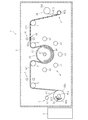
- 1 to 5 show the first embodiment of the method for producing a glass roll according to the present invention.
- the manufacturing equipment used in this method employs a roll-to-roll method, in which a functional film is formed on a transparent glass film drawn from a base glass roll and wound into a roll. This makes a glass roll.
- the glass film drawn out from the base glass roll is referred to as a first glass film
- the glass film after the functional film is formed is referred to as a second glass film.
- the manufacturing apparatus 1 includes a vacuum chamber 2, an unwinding apparatus 3, a film forming apparatus 4, a guide roller 5, sensors 6 and 7, a winding apparatus 8, and a control apparatus 9. , Equipped with.
- the vacuum chamber 2 houses the unwinding device 3, the film forming device 4, the guide roller 5, the sensors 6 and 7, and the winding device 8.
- the internal space of the vacuum chamber 2 is set to a predetermined degree of vacuum by a vacuum pump.
- An inert gas such as argon gas can be supplied into the vacuum chamber 2.
- the unwinding device 3 rotatably supports the base glass roll GR1 and pulls out the first glass film GF1 from the base glass roll GR1 and sends it out to the film forming apparatus 4.
- the unwinding device 3 can change the rotation speed of the base glass roll GR1 (the feeding speed of the first glass film GF1) under the control of the control device 9.
- the base glass roll GR1 mounted on the unwinding device 3 includes a first glass film GF1, a first lead film LF1 connected to a start end portion GFa of the first glass film GF1, and a terminal portion of the first glass film GF1. It includes a second lead film LF2 connected to GFb, a protective film PF1 overlaid on the first glass film GF1, and a winding core WC1.
- the first glass film GF1 and the lead films LF1 and LF2 are connected by an adhesive tape or other connecting member.
- the connecting portion between the start end portion GFa of the first glass film GF1 and the first lead film LF1 is referred to as the first connecting portion 10
- the connecting portion between the ending portion GFb of the first glass film GF1 and the second lead film LF2 is referred to as the first connecting portion 10.
- One end (starting end) of the second lead film LF2 is connected to the terminal GFb of the first glass film GF1 via the second connecting portion 11, and the other end (terminating portion) is connected to the winding core WC1. ing.
- the thickness of the first glass film GF1 is 500 ⁇ m or less, preferably 10 ⁇ m or more and 300 ⁇ m or less, and most preferably 30 ⁇ m or more and 200 ⁇ m or less.
- silicate glass and silica glass are used, preferably borosilicate glass, soda lime glass, aluminosilicate glass, and chemically strengthened glass, and most preferably non-alkali glass.
- the non-alkali glass is a glass that does not substantially contain an alkaline component (alkali metal oxide), and specifically, a glass having a weight ratio of an alkaline component of 3000 ppm or less. is there.
- the weight ratio of the alkaline component in the present invention is preferably 1000 ppm or less, more preferably 500 ppm or less, and most preferably 300 ppm or less.
- a resin film is used for each lead film LF1 and LF2.
- the lead films LF1 and LF2 include, for example, polyethylene terephthalate film, ionomer film, polyethylene film, polypropylene film, polyvinyl chloride film, polyvinylidene chloride film, polyvinyl alcohol film, polyester film, polycarbonate film, and polystyrene film.
- Polyacrylonitrile film ethylene vinyl acetate copolymer film, ethylene-vinyl alcohol copolymer film, ethylene-methacrylic acid copolymer film, nylon (registered trademark) film (polyamide film), polyimide film, organic resin such as cellophane A film (synthetic resin film) or the like can be used.
- the unwinding device 3 includes a protective film collecting unit 12 that winds up the protective film PF1 contained in the base glass roll GR1.
- the protective film collecting unit 12 is arranged at a position above the winding device 8, but is not limited to this position.
- the protective film recovery unit 12 recovers the protective film PF1 overlaid on the first glass film GF1 by peeling it off and winding it into a roll.
- the film forming apparatus 4 is composed of a heat film forming apparatus that conveys the first glass film GF1 while heating and forms a functional film on the first glass film GF1.
- the film forming apparatus 4 can form a functional film on the first glass film GF1 by various film forming methods such as a sputtering method, a vapor deposition method, and a CVD method.
- a sputtering method a vapor deposition method
- CVD method a vapor deposition method
- a transparent conductive film as a functional film for example, an ITO film is formed by a sputtering method will be described.
- the film forming apparatus 4 is composed of an ion beam sputtering apparatus, a magnetron sputtering apparatus, and the like.
- the film forming apparatus 4 as a sputtering apparatus mainly includes a plurality of sputtering sources 13 including a target and a heating unit 14 for heating the first glass film GF1.
- Each sputter source 13 is arranged at regular intervals from the heating unit 14 so that sputter particles (ITO particles) scattered from the target adhere to one surface of the first glass film GF1.
- the heating unit 14 is composed of a rotatable heating roller (can roller) that heats while contacting the first glass film GF1.
- the heating unit 14 includes a cylindrical roller body 15 that supports the first glass film GF1 and a heater 16 that heats the roller body 15.
- the roller body 15 is made of glass, ceramics, or metal.
- the roller body 15 is rotatably supported by the shaft portion 17.
- the heater 16 is arranged inside the roller body 15 in order to heat the roller body 15.
- the heater 16 is composed of, for example, an infrared heater or a near-infrared heater, but is not limited thereto.
- the plurality of guide rollers 5 are rotationally driven by a motor (not shown), but some of them may be composed of free rollers.
- the guide rollers 5 are arranged at intervals between the unwinding device 3 and the film forming apparatus 4 and between the film forming apparatus 4 and the winding device 8.
- the sensors 6 and 7 are the first sensor 6 arranged on the downstream side of the film forming apparatus 4 (between the film forming apparatus 4 and the winding device 8) and the upstream side of the film forming apparatus 4 (the unwinding device 3). It includes a second sensor 7 arranged between the film forming apparatus 4).
- Each of the sensors 6 and 7 is composed of a non-contact type sensor such as a transmission type laser sensor, but is not limited to this configuration.
- the first sensor 6 detects the first connecting portion 10 and the starting end portion GFa of the first glass film GF1 and transmits a detection signal to the control device 9.
- the second sensor 7 detects the terminal portion GFb of the second connecting portion 11 and the first glass film GF1 and transmits a detection signal to the control device 9.
- the winding device 8 forms a glass roll by superimposing the protective film PF2 on the second glass film and winding it around the winding core WC2.
- the take-up device 8 can change the rotation speed of the winding core WC2 under the control of the control device 9.
- the winding device 8 includes a protective film supply unit 18 that supplies the protective film PF2 to the second glass film wound around the winding core WC2.
- the protective film supply unit 18 is arranged at an upper position of the winding device 8, but is not limited to this position.
- the protective film supply unit 18 includes a protective film roll PFR, and supplies the protective film PF2 drawn from the protective film roll PFR to the second glass film.
- the control device 9 includes a computer (for example, a PC) that implements various hardware such as a CPU, ROM, RAM, HDD, input / output interface, and display.
- the control device 9 is communicably connected to the unwinding device 3, the guide roller 5, the film forming device 4, and the winding device 8, and controls the winding device 8, controls the rotation of the guide roller 5, and forms a film.
- the heating, film formation, control related to transportation, control of the winding device 8 and the like are executed.
- this method includes a start preparation step S1, a film formation step S2, and an end preparation step S3.
- the base glass roll GR1 is attached to the unwinding device 3, the first lead film LF1 is pulled out from the base glass roll GR1, and the starting end portion thereof is connected to the winding core WC2 of the winding device 8. Will be done.
- the vacuum chamber 2 is closed and the internal space thereof is set to a predetermined degree of vacuum. Further, the vacuum chamber 2 is filled with an inert gas.
- the control device 9 synchronously operates the unwinding device 3, the guide roller 5, the roller body 15 of the heating unit 14, and the winding device 8, and moves the first lead film LF1 upstream at a predetermined speed. It is conveyed from the unwinding device 3 to the winding device 8 on the downstream side.
- the transport speed of the first lead film LF1 is preferably constant in the range of 0.01 to 0.5 m / min, but is not limited to this range.
- the first lead film LF1 passes through the film forming apparatus 4 and is wound by the winding apparatus 8.
- the first glass film GF1 contained in the base glass roll GR1 is the base material when the first lead film LF1 that has passed through the film forming apparatus 4 is wound by the winding apparatus 8. It is pulled out from the glass roll GR1.
- the first glass film GF1 is conveyed together with the first lead film LF1 to the winding device 8 via the film forming apparatus 4.
- the first glass film GF1 is conveyed at the same speed as that of the first lead film LF1.
- the transport speed of the first glass film GF1 in the start preparation step S1 is set to be lower than the transport speed of the first glass film GF1 in the film forming step S2 described later.
- the start preparation step S1 includes a temperature raising step of raising the temperature of the film forming apparatus 4.
- the first sensor 6 detects the first connecting portion 10 and the starting end portion GFa of the first glass film GF1 when the first connecting portion 10 passes through the film forming apparatus 4, and detects a detection signal. Is transmitted to the control device 9.
- the control device 9 operates the heater 16 of the heating unit 14 and starts heating the roller main body 15.
- the first lead film LF1 is rolled by the roller during the execution of the temperature rising step. It does not come into contact with the main body 15.
- the roller body 15 is heated by the heater 16 so as to reach a predetermined film formation temperature or higher while guiding the first glass film GF1 to the downstream side.
- the temperature of the roller body 15 to be heated is set to, for example, 200 ° C. or higher and 500 ° C. or lower, but is not limited to this range.
- the sputtering source 13 does not operate and does not emit sputtered particles.
- the control device 9 starts the film forming step S2.
- the control device 9 controls the feeding speed of the unwinding device 3, the rotation speed of the roller main body 15, and the winding speed of the winding device 8 to increase the transport speed of the first glass film GF1.
- the transport speed of the first glass film GF1 in the film forming step S2 is preferably constant within the range of 0.1 to 10 m / min, but is not limited to this range.
- the roller body 15 guides the first glass film GF1 to the downstream side while heating it.
- the first glass film GF1 is heated to 150 ° C. or higher by the roller body 15.
- the first glass film GF1 is preferably heated to 200 ° C. or higher, more preferably 250 ° C. or higher, and most preferably 300 ° C. or higher.
- the film forming apparatus 4 scatters sputtering particles (for example, ITO particles) from a plurality of sputtering sources 13 and sequentially adheres them to the first glass film GF1 conveyed by the roller body 15.
- sputtering particles for example, ITO particles
- the first glass film GF1 When the first glass film GF1 is heated by the roller body 15, the ITO particles adhering to the first glass film GF1 crystallize, and a low resistance (for example, 20 ⁇ / ⁇ or less) functional film FM is formed. As a result, the second glass film GF2 is formed as shown in FIG.
- the protective film PF2 is superposed on the second glass film GF2 by the protective film supply unit 18, and the second glass film GF2 and the protective film PF2 are placed on the winding core WC2 by the winding device 8. Wrap around.
- the glass roll GR2 is formed around the winding core WC2.
- the outer diameter of the glass roll GR2 is expanded according to the rotation of the winding core WC2.
- the end preparation step S3 includes a temperature lowering step of lowering the temperature of the film forming apparatus 4 in order to prevent the second lead film LF2 from breaking. This temperature lowering step is started while the first glass film GF1 is passing through the film forming apparatus 4, and before the terminal GFb reaches the film forming apparatus 4.
- the control device 9 stops the heating by the heating unit 14.
- the control device 9 stops the sputtering source 13 of the film forming apparatus 4.
- the control device 9 controls the feeding speed of the unwinding device 3, the rotation speed of the heating roller, and the winding speed of the winding device 8 to control the transport speed of the first glass film GF1 and the second lead film LF2. It is set lower than the transport speed in the film step S2. More preferably, this transport speed is set lower than the transport speed of the first glass film GF1 in the start preparation step S1.
- the temperature lowering step the temperature is lowered while rotating the roller body 15 so that the temperature of the second lead film LF2 does not break (for example, 80 ° C. or lower) while the first glass film GF1 passes through the heating unit 14.
- the first glass film GF1 passes through the heating unit 14
- the second lead film LF2 connected to the terminal portion GFb of the first glass film GF1 reaches the heating unit 14.
- the second lead film LF2 is conveyed to the downstream side by the roller main body 15 without breaking.
- the end preparation step S3 is completed, and the glass roll GR2 is completed in a state of being supported by the winding apparatus 8.
- the glass roll GR 2 is taken out from the vacuum chamber 2 and sent to the next process.
- the second glass film GF2 is pulled out from the glass roll GR2, and a predetermined circuit pattern (for example, an electrode pattern) is formed on the functional film FM by means such as photolithography.
- a predetermined circuit pattern for example, an electrode pattern
- the protective film PF2 is removed (peeled) from the second glass film GF2.
- the roller body 15 rises to the film formation temperature so that the first lead film LF1 is not broken by the heat of the heating unit 14.
- the first glass film GF1 is brought to the heating unit 14 before heating, that is, before the start of the temperature raising step. Therefore, the roller body 15 of the heating unit 14 is heated by the heater 16 while conveying the first glass film GF1 without contacting the first lead film LF1. This makes it possible to reliably perform the film forming step S2 without melting the first lead film LF1.
- the second lead film LF2 is not broken by the heat of the heating unit 14. It passes through the film forming apparatus 4 and is wound by the winding apparatus 8.
- the transport speed of the first glass film GF1 in the start preparation step S1 and the end preparation step S3 is set lower than the transport speed of the first glass film GF1 in the film forming step S2, so that the temperature rise step is performed.
- the amount (length) of the first glass film GF1 that passes through the film forming apparatus 4 without being formed can be reduced as much as possible during the execution and the execution of the temperature lowering step.
- the transport speed of the first glass film GF1 in the end preparation step S3 is lower than the transport speed of the first glass film GF1 in the start preparation step S1, in the temperature lowering step which requires a longer time than the temperature raising step, The amount (length) of the first glass film GF1 that passes through the film forming apparatus 4 without being formed can be reduced as much as possible.
- the heating unit 14 does not include the roller main body 15, but includes a heater 16 that heats the first glass film GF1 without contacting the first glass film GF1.
- the sputtering source 13 and the heater 16 are arranged at a predetermined interval.
- a guide roller 5a for guiding the first lead film LF1, the first glass film GF1 and the second lead film LF2 between the sputtering source 13 and the heater 16 is arranged in the vicinity of the heater 16.
- the first glass film GF1 reaches the film forming apparatus 4 (heating unit 14) in the start preparation step S1
- the first connecting portion 10 and the first glass film GF1 are formed in the same manner as in the first embodiment.
- the start end portion GFa is detected by the first sensor 6, and the temperature raising step is started.
- the control device 9 controls the unwinding device 3, the guide rollers 5, 5a, and the winding device 8, and the first lead film LF1 and the first glass film.
- the GF1 is reciprocated on the transport path between the unwinding device 3 and the winding device 8.
- the first glass film GF1 is conveyed without breaking the first lead film LF1 and without detecting the first connecting portion 10 and the starting end portion GFa of the first glass film GF1 again by the first sensor 6. Can stay in the path.
- the amount of the first glass film GF1 wound around the winding device 8 can be reduced as much as possible without forming the functional film FM.
- the form of the reciprocating movement can also be applied to the first embodiment of the method for manufacturing a glass roll according to the present invention described in FIGS. 1 to 5.
- the control device 9 controls the unwinding device 3, the guide rollers 5, 5a, and the winding device 8 to end the reciprocating movement of the first glass film GF1 and the first glass film GF1. Is conveyed toward the winding device 8 on the downstream side.
- the film forming step S2 by the film forming apparatus 4 is executed.
- the control device 9 executes the end preparation step S3 as in the first embodiment.
- the present invention is not limited to the configuration of the above embodiment, and is not limited to the above-mentioned action and effect.
- the present invention can be modified in various ways without departing from the gist of the present invention.
- the transport speeds of the glass films GF1 and GF2 and the lead films LF1 and LF2 in the start preparation step S1 and the end preparation step S3 are set lower than the transport speeds of the glass films GF1 and GF2 in the film formation step S2.
- the present invention is not limited to this configuration.
- the transport of the glass films GF1 and GF2 and the lead films LF1 and LF2 may be temporarily stopped.
- the first glass film GF1 is conveyed at a low speed without stopping. Is desirable.
- the transport speed of the first glass film GF1 in the start preparation step S1 and the transport speed of the first glass film GF1 in the end preparation step S3 may be set to be equal. Further, the transport speed of the first glass film GF1 in the start preparation step S1 and the end preparation step S3 and the transport speed of the first glass film GF1 in the film forming step S2 may be set to be equal.
- the temperature raising step of the start preparation step S1 is started after the first connecting portion 10 and the starting end portion GFa of the first glass film GF1 have passed through the heating portion 14.
- the temperature raising step may be started while the first lead film LF1 is being conveyed to the roller body 15 of the heating unit 14. That is, in the present invention, the first glass film GF1 may reach the heating unit 14 during the execution of the temperature raising step (before the temperature of the roller body 15 reaches the film formation temperature).
- the heater 16 of the heating unit 14 is stopped and the heating unit 14 is naturally cooled in the vacuum chamber 2 in the temperature lowering step of the final preparation step S3, but the present invention is limited to this embodiment. Not done.
- the heating unit 14 may be cooled by injecting a refrigerant such as an inert gas toward the heating unit 14 from a nozzle arranged in the vacuum chamber 2.
- the transport speed of the first lead film is set to a relatively low speed (for example, 0.01 to 0.5 mm / min), but the present invention is not limited to this embodiment.
- the transfer speed in the film forming step S2 is until the sensor detects the first connecting portion 10 in the start preparation step S1.
- the speed for example, 1 to 15 m / min
- the lead time until the temperature raising step is started can be shortened.
- the heating speed may be set to a relatively low speed (for example, 0.01 to 0.5 m / min) and the temperature raising step may be started.
- the embodiment in which the transport speed of the first glass film GF1 is set lower than the transport speed of the first glass film GF1 in the start preparation step S1 in the end preparation step S3 has been described. It is not limited to the form.
- the transfer speed of the second lead film LF2 is increased to a high speed (for example, 1 to 15 m / min) in order to shorten the lead time. ) May be used.
- Unwinding device 4 Film forming device 8 Winding device 14 Heating unit (heating roller) FM functional film GF1 1st glass film GF2 2nd glass film GFa 1st glass film start end GFb 1st glass film end LF1 1st lead film LF2 2nd lead film GR2 glass roll S1 start preparation step S2 film formation Process S3 Completion preparation process
Landscapes
- Chemical & Material Sciences (AREA)
- Organic Chemistry (AREA)
- Engineering & Computer Science (AREA)
- Chemical Kinetics & Catalysis (AREA)
- Materials Engineering (AREA)
- Metallurgy (AREA)
- Mechanical Engineering (AREA)
- General Chemical & Material Sciences (AREA)
- Geochemistry & Mineralogy (AREA)
- Life Sciences & Earth Sciences (AREA)
- Surface Treatment Of Glass (AREA)
- Advancing Webs (AREA)
- Controlling Rewinding, Feeding, Winding, Or Abnormalities Of Webs (AREA)
- Physical Vapour Deposition (AREA)
- Controlling Sheets Or Webs (AREA)
- Re-Forming, After-Treatment, Cutting And Transporting Of Glass Products (AREA)
- Rolls And Other Rotary Bodies (AREA)
Abstract
ガラスロールの製造方法は、第一ガラスフィルムGF1の始端部GFaに連結された第一リードフィルムLF1を、巻出装置3から送り出して加熱成膜装置4を通過させた後に巻取装置8に巻き取らせる開始準備工程S1を備える。開始準備工程S1は、加熱成膜装置4を成膜温度まで昇温させる昇温工程を備える。第一ガラスフィルムGF1は、加熱成膜装置4が成膜温度まで昇温する前に、当該加熱成膜装置4に到達する。
Description
本発明は、機能性膜が形成されたガラスフィルムを巻き取ることでガラスロールを製造する方法に関する。
従来、ロールトゥロール(Roll to Roll)方式により、母材ガラスロールからガラスフィルムを引き出して所定の方向に搬送しつつ、当該ガラスフィルムに機能性膜を形成する技術が知られている。
例えば特許文献1には、母材ガラスロールから引き出された第一ガラスフィルムを所定の方向に送り出すガラスフィルム供給工程と、この第一ガラスフィルムに機能性膜(透明導電膜)を加熱成膜して第二ガラスフィルムを形成する成膜工程と、保護フィルムを第二ガラスフィルムに重ねて第三ガラスフィルムを形成する保護フィルム供給工程と、第三ガラスフィルムをロール状に巻き取ってガラスロールを構成する巻取工程と、を備えるガラスロールの製造方法が開示されている。
上記のように機能性膜が形成されたガラスフィルム(第三ガラスフィルム)をロール状に巻き取る場合、巻芯に当該ガラスフィルムを連結する必要がある。例えば特許文献2には、ガラスフィルムの破損を防止すべく、巻芯とガラスフィルムとを樹脂製のリードフィルム(リーダ)によって連結する技術が開示されている。
従来のようにロールトゥロール方式でガラスフィルムに機能性膜を形成する場合において、樹脂製のリードフィルムは、ガラスフィルムよりも耐熱性が低いため、成膜工程を通過する際に成膜装置からの熱によって破断するおそれがあった。
本発明は上記の事情に鑑みて為されたものであり、リードフィルムを破断させることなく、ガラスフィルムに加熱成膜を行うことを技術的課題とする。
本発明は上記の課題を解決するためのものであり、巻出装置から送り出された第一ガラスフィルムに加熱成膜装置によって機能性膜を形成することで第二ガラスフィルムを形成し、前記第二ガラスフィルムを巻取装置によって巻き取ることでガラスロールを製造する方法において、前記第一ガラスフィルムの始端部に連結された第一リードフィルムを、前記巻出装置から送り出して前記加熱成膜装置を通過させた後に前記巻取装置に巻き取らせる開始準備工程と、前記第一リードフィルムが前記加熱成膜装置を通過した後に、前記加熱成膜装置により前記第一ガラスフィルムに機能性膜を形成する成膜工程と、を備え、前記開始準備工程は、前記加熱成膜装置を成膜温度まで昇温させる昇温工程を備え、前記加熱成膜装置が前記成膜温度まで昇温する前に、前記第一ガラスフィルムが前記加熱成膜装置に到達することを特徴とする。
かかる構成によれば、加熱成膜装置が成膜温度に達する前に、第一ガラスフィルムに連結された第一リードフィルムは、当該加熱成膜装置を通過することができる。これにより、第一リードフィルムを破断させることなく、第一ガラスフィルムに加熱成膜を行うことが可能になる。なお、「加熱装置が成膜温度まで昇温する前」とは、昇温工程の開始後のみならず、昇温工程の開始前を含む。
前記昇温工程は、前記第一ガラスフィルムと前記第一リードフィルムとの連結部が前記加熱成膜装置を通過した後に開始してもよい。第一リードフィルムが全て加熱成膜装置を通過した後に昇温工程を開始することで、成膜工程による第一リードフィルムの破断を確実に防止できる。
本発明に係るガラスロールの製造方法では、前記昇温工程における前記加熱成膜装置の昇温中に、前記第一ガラスフィルムが前記加熱成膜装置に到達してもよい。
本発明に係るガラスロールの製造方法は、前記第一ガラスフィルムの終端部に連結された第二リードフィルムを、前記巻出装置から送り出して前記加熱成膜装置を通過させた後に前記巻取装置に巻き取らせる終了準備工程を備え、前記終了準備工程は、前記加熱成膜装置を降温させる降温工程を備え、前記第一ガラスフィルムの前記終端部が前記加熱成膜装置に到達する前に前記降温工程を開始してもよい。
かかる構成によれば、第一ガラスフィルムが加熱成膜装置を通過している間に降温工程を開始することで、第二リードフィルムが加熱成膜装置に到達するまでに、加熱成膜装置の温度を当該第二リードフィルムが破断しない温度まで低下させることが可能になる。
本発明に係るガラスロールの製造方法において、前記加熱成膜装置は、前記第一ガラスフィルムに接触して加熱しながら搬送する加熱ローラを備え、前記開始準備工程における前記第一ガラスフィルムの搬送速度が、前記成膜工程における前記第一ガラスフィルムの搬送速度よりも低く設定されてもよい。
かかる構成によれば、開始準備工程における搬送速度を成膜工程における搬送速度よりも低く設定することで、開始準備工程において成膜されることなく搬送される第一ガラスフィルムの量を可及的に低減できる。
本発明に係るガラスロール製造方法において、前記終了準備工程における前記第一ガラスフィルムの搬送速度が、前記成膜工程における前記第一ガラスフィルムの搬送速度よりも低く設定されてもよい。
かかる構成によれば、終了準備工程における搬送速度を成膜工程における搬送速度よりも低く設定することで、終了準備工程において成膜されることなく搬送される第一ガラスフィルムの量を可及的に低減できる。
本発明に係るガラスロールの製造方法において、前記終了準備工程における前記第一ガラスフィルムの搬送速度が、前記開始準備工程における前記第一ガラスフィルムの搬送速度よりも低く設定されてもよい。
終了準備工程の降温工程に要する時間は、開始準備工程の昇温工程に要する時間よりも長くなる。このため、終了準備工程に係る搬送速度を開始準備工程に係る搬送速度よりも低く設定することで、第二リードフィルムが加熱成膜装置に到達するまでの時間をより長く確保できる。
本発明に係るガラスロールの製造方法では、前記昇温工程において、前記第一ガラスフィルムが前記加熱成膜装置に到達した後に、前記第一ガラスフィルムを前記巻出装置と前記巻取装置との間で往復移動させてもよい。これにより、開始準備工程において成膜されることなく搬送される第一ガラスフィルムの量を可及的に低減できる。
本発明によれば、リードフィルムを破断させることなく、ガラスフィルムに加熱成膜を行うことができる。
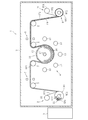
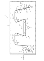
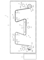
以下、本発明を実施するための形態について、図面を参照しながら説明する。図1乃至図5は、本発明に係るガラスロールの製造方法の第一実施形態を示す。
本方法に使用される製造装置は、ロールトゥロール(Roll to Roll)方式を採用しており、母材ガラスロールから引き出された透明なガラスフィルムに機能性膜を形成し、ロール状に巻き取ることでガラスロールを製造する。以下、母材ガラスロールから引き出されるガラスフィルムを第一ガラスフィルムといい、機能性膜が形成された後のガラスフィルムを第二ガラスフィルムという。
図1に示すように、製造装置1は、真空チャンバ2と、巻出装置3と、成膜装置4と、ガイドローラ5と、センサ6,7と、巻取装置8と、制御装置9と、を備える。
真空チャンバ2は、巻出装置3、成膜装置4、ガイドローラ5、センサ6,7及び巻取装置8を内部に収容する。真空チャンバ2の内部空間は、真空ポンプにより所定の真空度に設定される。真空チャンバ2内には、アルゴンガス等の不活性ガスが供給され得る。
巻出装置3は、母材ガラスロールGR1を回転可能に支持するとともに、当該母材ガラスロールGR1から第一ガラスフィルムGF1を引き出して成膜装置4へと送り出す。巻出装置3は、制御装置9の制御により、母材ガラスロールGR1の回転速度(第一ガラスフィルムGF1の送り出し速度)を変更できる。
巻出装置3に装着される母材ガラスロールGR1は、第一ガラスフィルムGF1と、第一ガラスフィルムGF1の始端部GFaに連結される第一リードフィルムLF1と、第一ガラスフィルムGF1の終端部GFbに連結される第二リードフィルムLF2と、第一ガラスフィルムGF1に重ねられる保護フィルムPF1と、巻芯WC1とを含む。
第一ガラスフィルムGF1と各リードフィルムLF1,LF2は、粘着テープその他の連結部材により連結されている。以下、第一ガラスフィルムGF1の始端部GFaと第一リードフィルムLF1との連結部を第一連結部10といい、第一ガラスフィルムGF1の終端部GFbと第二リードフィルムLF2との連結部を第二連結部11という。第二リードフィルムLF2は、その一端部(始端部)が第二連結部11を介して第一ガラスフィルムGF1の終端部GFbと連結され、その他端部(終端部)が巻芯WC1に連結されている。
第一ガラスフィルムGF1の厚みは、500μm以下とされ、好ましくは10μm以上300μm以下とされ、最も好ましくは30μm以上200μm以下である。
第一ガラスフィルムGF1の材料としては、ケイ酸塩ガラス、シリカガラスが用いられ、好ましくはホウ珪酸ガラス、ソーダライムガラス、アルミノ珪酸塩ガラス、化学強化ガラスが用いられ、最も好ましくは無アルカリガラスが用いられる。ここで、無アルカリガラスとは、アルカリ成分(アルカリ金属酸化物)が実質的に含まれていないガラスのことであって、具体的には、アルカリ成分の重量比が3000ppm以下のガラスのことである。本発明におけるアルカリ成分の重量比は、好ましくは1000ppm以下であり、より好ましくは500ppm以下であり、最も好ましくは300ppm以下である。
各リードフィルムLF1,LF2には樹脂製のフィルムが使用される。具体的には、各リードフィルムLF1,LF2として、例えば、ポリエチレンテレフタレートフィルム、アイオノマーフィルム、ポリエチレンフィルム、ポリプロピレンフィルム、ポリ塩化ビニルフィルム、ポリ塩化ビニリデンフィルム、ポリビニルアルコールフィルム、ポリエステルフィルム、ポリカーボネートフィルム、ポリスチレンフィルム、ポリアクリロニトリルフィルム、エチレン酢酸ビニル共重合体フィルム、エチレン-ビニルアルコール共重合体フィルム、エチレン-メタクリル酸共重合体フィルム、ナイロン(登録商標)フィルム(ポリアミドフィルム)、ポリイミドフィルム、セロファンなどの有機樹脂フィルム(合成樹脂フィルム)などを使用することができる。
巻出装置3は、母材ガラスロールGR1に含まれる保護フィルムPF1を巻き取る保護フィルム回収部12を備える。保護フィルム回収部12は、巻取装置8の上方の位置に配されているが、この位置に限定されるものではない。保護フィルム回収部12は、第一ガラスフィルムGF1に重ねられている保護フィルムPF1を剥離させるとともに、ロール状に巻き取ることによって回収する。
成膜装置4は、第一ガラスフィルムGF1を加熱しながら搬送し、当該第一ガラスフィルムGF1に機能性膜を形成する加熱成膜装置により構成される。成膜装置4は、スパッタリング法、蒸着法、CVD法等の各種成膜法により、第一ガラスフィルムGF1に機能性膜を形成できる。本実施形態では、スパッタリング法により機能性膜としての透明導電膜、例えばITO膜を形成する場合について説明する。
成膜装置4は、イオンビームスパッタ装置やマグネトロンスパッタ装置などにより構成される。スパッタ装置としての成膜装置4は、ターゲットを含む複数のスパッタ源13と、第一ガラスフィルムGF1を加熱する加熱部14とを主に備える。
各スパッタ源13は、ターゲットから飛散するスパッタ粒子(ITO粒子)が第一ガラスフィルムGF1の一方の面に付着するように、加熱部14から一定の間隔をおいて配置される。
加熱部14は、第一ガラスフィルムGF1に接触しつつ加熱する回転可能な加熱ローラ(キャンローラ)により構成される。加熱部14は、第一ガラスフィルムGF1を支持する円筒状のローラ本体15と、このローラ本体15を加熱するヒータ16とを備える。
ローラ本体15は、ガラス、セラミックス、又は金属により構成される。ローラ本体15は、軸部17により回転自在に支持されている。
ヒータ16は、ローラ本体15を加熱すべく、当該ローラ本体15の内側に配置される。ヒータ16は、例えば赤外線ヒータ又は近赤外線ヒータにより構成されるが、これらに限定されるものではない。
複数のガイドローラ5は、図示しないモータにより回転駆動されるが、その一部がフリーローラにより構成されてもよい。ガイドローラ5は、巻出装置3と成膜装置4との間、及び成膜装置4と巻取装置8との間に間隔をおいて配置されている。
センサ6,7は、成膜装置4の下流側(成膜装置4と巻取装置8との間)に配される第一センサ6と、成膜装置4の上流側(巻出装置3と成膜装置4との間)に配される第二センサ7とを含む。各センサ6,7は、例えば透過型レーザセンサ等の非接触式のセンサにより構成されるが、この構成に限定されるものではない。
第一センサ6は、第一連結部10及び第一ガラスフィルムGF1の始端部GFaを検出するとともに検出信号を制御装置9に送信する。第二センサ7は、第二連結部11及び第一ガラスフィルムGF1の終端部GFbを検出するとともに、検出信号を制御装置9に送信する。
巻取装置8は、第二ガラスフィルムに保護フィルムPF2を重ねて巻芯WC2に巻き付けることで、ガラスロールを形成する。巻取装置8は、制御装置9の制御により、巻芯WC2の回転速度を変更できる。
巻取装置8は、巻芯WC2に巻き取られる第二ガラスフィルムに保護フィルムPF2を供給する保護フィルム供給部18を備える。保護フィルム供給部18は、巻取装置8の上方位置に配されているが、この位置に限定されるものではない。保護フィルム供給部18は、保護フィルムロールPFRを備えており、保護フィルムロールPFRから引き出された保護フィルムPF2を第二ガラスフィルムに供給する。
制御装置9は、例えばCPU、ROM、RAM、HDD、入出力インターフェース、ディスプレイ等の各種ハードウェアを実装するコンピュータ(例えばPC)を含む。制御装置9は、巻出装置3、ガイドローラ5、成膜装置4及び巻取装置8に通信可能に接続されており、巻取装置8の制御、ガイドローラ5の回転制御、成膜装置4の加熱、成膜、搬送に係る制御、巻取装置8の制御等を実行する。
以下、上記構成の製造装置1を使用して、ガラスロールを製造する方法について説明する。本方法は、図2に示すように、開始準備工程S1と、成膜工程S2と、終了準備工程S3とを備える。
開始準備工程S1において、母材ガラスロールGR1が巻出装置3に装着され、当該母材ガラスロールGR1から第一リードフィルムLF1が引き出され、その始端部が巻取装置8の巻芯WC2に連結される。その後、真空チャンバ2が閉じられ、その内部空間が所定の真空度に設定される。また、真空チャンバ2内には、不活性ガスが充填される。
次に、制御装置9は、巻出装置3、ガイドローラ5、加熱部14のローラ本体15、及び巻取装置8を同期して作動させ、所定の速度で第一リードフィルムLF1を上流側の巻出装置3から下流側の巻取装置8へと搬送する。この場合における第一リードフィルムLF1の搬送速度は、0.01~0.5m/minの範囲で一定とされることが望ましいが、この範囲に限定されるものではない。第一リードフィルムLF1は、成膜装置4を通過し、巻取装置8によって巻き取られる。
開始準備工程S1において、母材ガラスロールGR1に含まれている第一ガラスフィルムGF1は、成膜装置4を通過した第一リードフィルムLF1が巻取装置8に巻き取られることによって、当該母材ガラスロールGR1から引き出される。第一ガラスフィルムGF1は、第一リードフィルムLF1とともに成膜装置4を経て巻取装置8へと搬送される。このとき、第一ガラスフィルムGF1は、第一リードフィルムLF1の搬送速度と同じ速度で搬送される。開始準備工程S1における第一ガラスフィルムGF1の搬送速度は、後述する成膜工程S2における第一ガラスフィルムGF1の搬送速度よりも低く設定されている。
開始準備工程S1は、成膜装置4を昇温させる昇温工程を備える。図3に示すように、第一センサ6は、第一連結部10が成膜装置4を通過したときに、第一連結部10及び第一ガラスフィルムGF1の始端部GFaを検出し、検出信号を制御装置9に送信する。これにより、制御装置9は、加熱部14のヒータ16を作動させ、ローラ本体15の加熱を開始する。この昇温工程の開始時において、第一連結部10及び第一ガラスフィルムGF1の始端部GFaが成膜装置4を通過しているため、昇温工程の実行中において第一リードフィルムLF1がローラ本体15に接触することはない。
ローラ本体15は、第一ガラスフィルムGF1を下流側に案内しながらヒータ16により所定の成膜温度以上となるように加熱される。加熱されるローラ本体15の温度は、例えば200℃以上500℃以下に設定されるが、この範囲に限定されない。なお、昇温工程の実行中において、スパッタ源13は作動せず、スパッタ粒子を放出しない。
制御装置9は、昇温工程が完了すると(ローラ本体15が所定の成膜温度以上に加熱されると)、成膜工程S2を開始する。制御装置9は、巻出装置3の送り出し速度、ローラ本体15の回転速度、及び巻取装置8の巻取速度を制御し、第一ガラスフィルムGF1の搬送速度を増加させる。成膜工程S2における第一ガラスフィルムGF1の搬送速度は、0.1~10m/minの範囲内で一定とされることが望ましいが、この範囲に限定されるものではない。
ローラ本体15は、第一ガラスフィルムGF1を加熱しながら下流側に案内する。第一ガラスフィルムGF1は、ローラ本体15によって150℃以上に加熱される。スパッタ粒子がITOである場合、第一ガラスフィルムGF1は、200℃以上に加熱されることが望ましく、250℃に加熱されることが更に望ましく、300℃以上に加熱されることが最も望ましい。
制御装置9の制御により、成膜装置4は、複数のスパッタ源13からスパッタ粒子(例えばITO粒子)を飛散させ、ローラ本体15により搬送されている第一ガラスフィルムGF1に順次付着させる。
ローラ本体15によって第一ガラスフィルムGF1が加熱されることで、当該第一ガラスフィルムGF1に付着したITO粒子が結晶化し、低抵抗(例えば20Ω/□以下)の機能性膜FMが形成される。これにより、図4に示すように第二ガラスフィルムGF2が形成される。
図4に示すように、成膜工程S2では、保護フィルム供給部18によって保護フィルムPF2を第二ガラスフィルムGF2に重ねつつ、巻取装置8によって巻芯WC2に第二ガラスフィルムGF2および保護フィルムPF2を巻き付ける。これにより、巻芯WC2の周囲にガラスロールGR2が形成される。ガラスロールGR2は、巻芯WC2の回転に応じてその外径を拡大する。
成膜工程S2が終了に近づくと、全ての第一ガラスフィルムGF1が巻出装置3から送り出される。その後、第二連結部11が巻出装置3から送り出される。図5に示すように、第二連結部11が第二センサ7に到達すると、第二センサ7は、当該第二連結部11及び第一ガラスフィルムGF1の終端部GFbを検出し、検出信号を制御装置9に送信する。
第二センサ7から信号を受信すると、制御装置9は、終了準備工程S3を開始する。終了準備工程S3は、第二リードフィルムLF2の破断を防止するために成膜装置4を降温させる降温工程を備える。この降温工程は、第一ガラスフィルムGF1が成膜装置4を通過している間であって、終端部GFbが成膜装置4に到達する前に開始する。
降温工程において、制御装置9は、加熱部14による加熱を停止させる。ヒータ16が停止することで、ローラ本体15の温度は徐々に低下する。また、制御装置9は、成膜装置4のスパッタ源13を停止させる。さらに制御装置9は、巻出装置3の送り出し速度、加熱ローラの回転速度、及び巻取装置8の巻取速度を制御し、第一ガラスフィルムGF1及び第二リードフィルムLF2の搬送速度を、成膜工程S2における搬送速度よりも低く設定する。より好ましくは、この搬送速度は、開始準備工程S1における第一ガラスフィルムGF1の搬送速度よりも低く設定される。
降温工程では、第一ガラスフィルムGF1が加熱部14を通過している間に、第二リードフィルムLF2が破断しない温度(例えば80℃以下)になるように、当該ローラ本体15を回転させながら降温させる。第一ガラスフィルムGF1が加熱部14を通過すると、当該第一ガラスフィルムGF1の終端部GFbに連結された第二リードフィルムLF2が当該加熱部14に到達する。このとき、ローラ本体15の温度が十分に低下しているため、第二リードフィルムLF2は破断することなく当該ローラ本体15によって下流側に搬送される。
成膜装置4を通過した第二リードフィルムLF2が巻取装置8に巻き取られると、終了準備工程S3が終了し、ガラスロールGR2が巻取装置8に支持された状態で完成する。ガラスロールGR2は真空チャンバ2から取り出され、次工程へと送られる。
なお、その後の工程において、ガラスロールGR2から第二ガラスフィルムGF2が引き出され、フォトリソグラフィ等の手段により、機能性膜FMに所定の回路パターン(例えば電極パターン)が形成される。所定の製造関連処理が実行されると、保護フィルムPF2は、第二ガラスフィルムGF2から除去(剥離)される。
以上説明した本実施形態に係るガラスロールGR2の製造方法によれば、開始準備工程S1において、第一リードフィルムLF1が加熱部14の熱によって破断しないように、ローラ本体15が成膜温度まで昇温する前、すなわち昇温工程の開始前に第一ガラスフィルムGF1を加熱部14に到達させている。したがって、加熱部14のローラ本体15は、第一リードフィルムLF1に接触することなく、第一ガラスフィルムGF1を搬送しながらヒータ16によって加熱される。これにより、第一リードフィルムLF1を溶解させることなく、成膜工程S2を確実に行うことが可能になる。
また、終了準備工程S3において、第一ガラスフィルムGF1が成膜装置4を通過している間に降温工程を実行することで、第二リードフィルムLF2は、加熱部14の熱によって破断することなく成膜装置4を通過し、巻取装置8に巻き取られる。
本実施形態では、開始準備工程S1及び終了準備工程S3における第一ガラスフィルムGF1の搬送速度を、成膜工程S2における第一ガラスフィルムGF1の搬送速度よりも低く設定することで、昇温工程の実行中及び降温工程の実行中に、成膜されることなく成膜装置4を通過する第一ガラスフィルムGF1の量(長さ)を可及的に低減できる。
また、終了準備工程S3における第一ガラスフィルムGF1の搬送速度を開始準備工程S1における第一ガラスフィルムGF1の搬送速度よりも低く設定することで、昇温工程よりも時間を長く要する降温工程において、成膜されることなく成膜装置4を通過する第一ガラスフィルムGF1の量(長さ)を可及的に低減できる。
図6及び図7は、本発明の第二実施形態を示す。本実施形態では、製造装置1における成膜装置4の構成が第一実施形態と異なる。本実施形態に係る加熱部14は、ローラ本体15を備えておらず、第一ガラスフィルムGF1に接触することなく当該第一ガラスフィルムGF1を加熱するヒータ16を備える。スパッタ源13とヒータ16とは所定の間隔をおいて配されている。ヒータ16の近傍位置には、第一リードフィルムLF1、第一ガラスフィルムGF1及び第二リードフィルムLF2をスパッタ源13とヒータ16との間に案内するガイドローラ5aが配されている。
本実施形態におけるその他の構成は第一実施形態と同じである。本実施形態において第一実施形態と共通する構成要素には、第一実施形態と同じ符号を付している。
以下、上記構成の製造装置1を使用してガラスロールGR2を製造する方法について説明する。本実施形態では、開始準備工程S1において、第一ガラスフィルムGF1が成膜装置4(加熱部14)に到達した後に、第一実施形態と同様に第一連結部10及び第一ガラスフィルムGF1の始端部GFaを第一センサ6によって検出させ、昇温工程を開始させる。
図6に示すように、昇温工程の実行中において、制御装置9は、巻出装置3、ガイドローラ5,5a、及び巻取装置8を制御し、第一リードフィルムLF1及び第一ガラスフィルムGF1を巻出装置3と巻取装置8との間の搬送経路上で往復移動させる。この場合において、第一連結部10及び第一ガラスフィルムGF1の始端部GFaは、第一センサ6の下流側の領域で往復移動することが望ましい。これにより、第一リードフィルムLF1が破断することなく、かつ第一連結部10及び第一ガラスフィルムGF1の始端部GFaが第一センサ6に再度検出されることなく、第一ガラスフィルムGF1を搬送経路に留まらせることができる。この往復移動により、機能性膜FMが形成されることなく巻取装置8に巻き取られる第一ガラスフィルムGF1の量を可及的に低減できる。なお、当該往復移動の形態は、図1乃至図5に記載されている本発明に係るガラスロールの製造方法の第一実施形態にも適用可能である。
昇温工程が完了すると、制御装置9は、巻出装置3、ガイドローラ5,5a及び巻取装置8を制御し、第一ガラスフィルムGF1の往復移動を終了させるとともに、当該第一ガラスフィルムGF1を下流側の巻取装置8に向かって搬送させる。その後、図7に示すように、成膜装置4による成膜工程S2を実行する。成膜工程S2が終了すると、制御装置9は、第一実施形態と同様に終了準備工程S3を実行する。
なお、本発明は、上記実施形態の構成に限定されるものではなく、上記した作用効果に限定されるものでもない。本発明は、本発明の要旨を逸脱しない範囲で種々の変更が可能である。
上記の実施形態では、開始準備工程S1及び終了準備工程S3におけるガラスフィルムGF1,GF2及びリードフィルムLF1,LF2の搬送速度を、成膜工程S2におけるガラスフィルムGF1,GF2の搬送速度よりも低く設定してガラスフィルムGF1,GF2及びリードフィルムLF1,LF2を搬送する例を示したが、本発明は、この構成に限定されるものではない。例えば、開始準備工程S1、終了準備工程S3において、ガラスフィルムGF1,GF2及びリードフィルムLF1,LF2の搬送を一時的に停止させてもよい。但し、加熱部14のローラ本体15の熱膨張・収縮により、ローラ本体15とガラスフィルムGF1,GF2とが擦過するおそれがある場合には、第一ガラスフィルムGF1を停止させることなく低速で搬送することが望ましい。
また、開始準備工程S1における第一ガラスフィルムGF1の搬送速度と終了準備工程S3における第一ガラスフィルムGF1の搬送速度とを等しく設定してもよい。また、開始準備工程S1及び終了準備工程S3における第一ガラスフィルムGF1の搬送速度と成膜工程S2における第一ガラスフィルムGF1の搬送速度とを等しく設定してもよい。
上記の実施形態では、第一連結部10及び第一ガラスフィルムGF1の始端部GFaが加熱部14を通過した後に、開始準備工程S1の昇温工程を開始させた例を示したが、本発明はこの構成に限定されるものではない。例えば、第一リードフィルムLF1が加熱部14のローラ本体15に搬送されている間に昇温工程を開始してもよい。すなわち、本発明では、昇温工程の実行中(ローラ本体15が成膜温度まで昇温する前)に第一ガラスフィルムGF1を加熱部14に到達させればよい。
上記の実施形態では、終了準備工程S3の降温工程において加熱部14のヒータ16を停止させ、当該加熱部14を真空チャンバ2内で自然冷却させる例を示したが、本発明はこの態様に限定されない。例えば、降温工程において、真空チャンバ2内に配されたノズルから加熱部14に向かって不活性ガス等の冷媒を噴射させることで、当該加熱部14を冷却してもよい。
上記の実施形態では、開始準備工程S1において、第一リードフィルムの搬送速度を比較的低速(例えば0.01~0.5mm/min)としたが、この形態には限定されない。例えば、第1センサ6の位置を適宜調整するか、センサの個数を増加させることで、開始準備工程S1において、センサが第一連結部10を検出するまでの間を成膜工程S2における搬送速度(例えば0.1~10m/min)よりも高速の速度(例えば1~15m/min)とすることで、昇温工程を開始するまでのリードタイムを短縮することができる。この場合においては、センサが第一連結部10を検出した後に、搬送速度を比較的低速(例えば0.01~0.5m/min)として、昇温工程を開始しても良い。
上記の実施形態では、終了準備工程S3において、第一ガラスフィルムGF1の搬送速度を開始準備工程S1における第一ガラスフィルムGF1の搬送速度よりも低く設定する実施形態で説明を行ったが、この実施形態には限定されない。例えば、終了準備工程S3において、降温工程終了後に十分に成膜装置4の温度が下がった場合は、リードタイムを短縮するため、第二リードフィルムLF2の搬送速度を高速(例えば1~15m/min)としても良い。
3 巻出装置
4 成膜装置
8 巻取装置
14 加熱部(加熱ローラ)
FM 機能性膜
GF1 第一ガラスフィルム
GF2 第二ガラスフィルム
GFa 第一ガラスフィルムの始端部
GFb 第一ガラスフィルムの終端部
LF1 第一リードフィルム
LF2 第二リードフィルム
GR2 ガラスロール
S1 開始準備工程
S2 成膜工程
S3 終了準備工程
4 成膜装置
8 巻取装置
14 加熱部(加熱ローラ)
FM 機能性膜
GF1 第一ガラスフィルム
GF2 第二ガラスフィルム
GFa 第一ガラスフィルムの始端部
GFb 第一ガラスフィルムの終端部
LF1 第一リードフィルム
LF2 第二リードフィルム
GR2 ガラスロール
S1 開始準備工程
S2 成膜工程
S3 終了準備工程
Claims (8)
- 巻出装置から送り出された第一ガラスフィルムに加熱成膜装置によって機能性膜を形成することで第二ガラスフィルムを形成し、前記第二ガラスフィルムを巻取装置によって巻き取ることでガラスロールを製造する方法において、
前記第一ガラスフィルムの始端部に連結された第一リードフィルムを、前記巻出装置から送り出して前記加熱成膜装置を通過させた後に前記巻取装置に巻き取らせる開始準備工程と、
前記第一リードフィルムが前記加熱成膜装置を通過した後に、前記加熱成膜装置により前記第一ガラスフィルムに機能性膜を形成する成膜工程と、を備え、
前記開始準備工程は、前記加熱成膜装置を成膜温度まで昇温させる昇温工程を備え、
前記加熱成膜装置が前記成膜温度まで昇温する前に、前記第一ガラスフィルムが前記加熱成膜装置に到達することを特徴とするガラスロールの製造方法。 - 前記昇温工程は、前記第一ガラスフィルムと前記第一リードフィルムとの連結部が前記加熱成膜装置を通過した後に開始する請求項1に記載のガラスロールの製造方法。
- 前記昇温工程における前記加熱成膜装置の昇温中に、前記第一ガラスフィルムが前記加熱成膜装置に到達する請求項1に記載のガラスロールの製造方法。
- 前記第一ガラスフィルムの終端部に連結された第二リードフィルムを、前記巻出装置から送り出して前記加熱成膜装置を通過させた後に前記巻取装置に巻き取らせる終了準備工程を備え、
前記終了準備工程は、前記加熱成膜装置を降温させる降温工程を備え、
前記第一ガラスフィルムの前記終端部が前記加熱成膜装置に到達する前に前記降温工程を開始する請求項1から3のいずれか一項に記載のガラスロールの製造方法。 - 前記加熱成膜装置は、前記第一ガラスフィルムに接触して加熱しながら搬送する加熱ローラを備え、
前記開始準備工程における前記第一ガラスフィルムの搬送速度が、前記成膜工程における前記第一ガラスフィルムの搬送速度よりも低く設定される請求項1から4のいずれか一項に記載のガラスロールの製造方法。 - 前記加熱成膜装置は、前記第一ガラスフィルムに接触して加熱しながら搬送する加熱ローラを備え、
前記終了準備工程における前記第一ガラスフィルムの搬送速度が、前記成膜工程における前記第一ガラスフィルムの搬送速度よりも低く設定される請求項4に記載のガラスロールの製造方法。 - 前記加熱成膜装置は、前記第一ガラスフィルムに接触して加熱しながら搬送する加熱ローラを備え、
前記終了準備工程における前記第一ガラスフィルムの搬送速度が、前記開始準備工程における前記第一ガラスフィルムの搬送速度よりも低く設定される請求項4に記載のガラスロールの製造方法。 - 前記昇温工程において、前記第一ガラスフィルムが前記加熱成膜装置に到達した後に、前記第一ガラスフィルムを前記巻出装置と前記巻取装置との間で往復移動させる請求項1から7のいずれか一項に記載のガラスロールの製造方法。
Priority Applications (4)
| Application Number | Priority Date | Filing Date | Title |
|---|---|---|---|
| KR1020217037487A KR102670242B1 (ko) | 2019-06-11 | 2020-05-22 | 유리 롤의 제조 방법 |
| DE112020002825.9T DE112020002825T5 (de) | 2019-06-11 | 2020-05-22 | Verfahren zur Herstellung einer Glasrolle |
| CN202080028244.4A CN113677642B (zh) | 2019-06-11 | 2020-05-22 | 玻璃卷的制造方法 |
| US17/612,733 US11946133B2 (en) | 2019-06-11 | 2020-05-22 | Glass roll production method |
Applications Claiming Priority (2)
| Application Number | Priority Date | Filing Date | Title |
|---|---|---|---|
| JP2019-108654 | 2019-06-11 | ||
| JP2019108654A JP7262703B2 (ja) | 2019-06-11 | 2019-06-11 | ガラスロールの製造方法 |
Publications (1)
| Publication Number | Publication Date |
|---|---|
| WO2020250646A1 true WO2020250646A1 (ja) | 2020-12-17 |
Family
ID=73742473
Family Applications (1)
| Application Number | Title | Priority Date | Filing Date |
|---|---|---|---|
| PCT/JP2020/020395 Ceased WO2020250646A1 (ja) | 2019-06-11 | 2020-05-22 | ガラスロールの製造方法 |
Country Status (7)
| Country | Link |
|---|---|
| US (1) | US11946133B2 (ja) |
| JP (1) | JP7262703B2 (ja) |
| KR (1) | KR102670242B1 (ja) |
| CN (1) | CN113677642B (ja) |
| DE (1) | DE112020002825T5 (ja) |
| TW (1) | TWI838533B (ja) |
| WO (1) | WO2020250646A1 (ja) |
Families Citing this family (1)
| Publication number | Priority date | Publication date | Assignee | Title |
|---|---|---|---|---|
| CN116377409B (zh) * | 2023-01-31 | 2025-08-12 | 深圳天成真空技术有限公司 | 一种复合型多功能卷绕镀膜机 |
Citations (7)
| Publication number | Priority date | Publication date | Assignee | Title |
|---|---|---|---|---|
| WO2012090693A1 (ja) * | 2010-12-28 | 2012-07-05 | コニカミノルタホールディングス株式会社 | ガラスロールの処理装置及び処理方法 |
| JP2013124413A (ja) * | 2011-12-16 | 2013-06-24 | Nippon Electric Glass Co Ltd | 成膜装置及び膜付ガラスフィルムの製造方法 |
| JP2014051429A (ja) * | 2012-08-07 | 2014-03-20 | Kobe Steel Ltd | ガラスフィルム搬送装置 |
| JP2014109073A (ja) * | 2012-12-03 | 2014-06-12 | Samsung Corning Precision Materials Co Ltd | ロール・ツー・ロールスパッタリング方法 |
| JP2016041630A (ja) * | 2015-10-22 | 2016-03-31 | 株式会社神戸製鋼所 | ガラスフィルム搬送装置 |
| JP2018188320A (ja) * | 2017-04-28 | 2018-11-29 | 日本電気硝子株式会社 | ガラスロールの製造方法及びガラスロール |
| WO2019102836A1 (ja) * | 2017-11-24 | 2019-05-31 | 日本電気硝子株式会社 | 透明導電膜付きガラスシート、透明導電膜付きガラスロール、及びその製造方法 |
Family Cites Families (13)
| Publication number | Priority date | Publication date | Assignee | Title |
|---|---|---|---|---|
| CH663510GA3 (en) * | 1981-04-16 | 1987-12-31 | Textile structures bonded to one another to form a web material | |
| JPH03234566A (ja) * | 1990-02-09 | 1991-10-18 | Mitsubishi Electric Corp | インクシートロール |
| JP5532507B2 (ja) * | 2008-10-01 | 2014-06-25 | 日本電気硝子株式会社 | ガラスロール及びガラスロールの処理方法 |
| JP5720885B2 (ja) * | 2010-03-03 | 2015-05-20 | 日本電気硝子株式会社 | ガラスロール、及びガラスロールの製造方法 |
| JP2012001405A (ja) * | 2010-06-18 | 2012-01-05 | Konica Minolta Holdings Inc | 薄膜ガラスの搬送方法、及び薄膜ガラスの搬送装置 |
| JP5691940B2 (ja) * | 2011-08-30 | 2015-04-01 | 住友金属鉱山株式会社 | 長尺ガラスフィルムの処理方法および処理装置 |
| US9428359B2 (en) * | 2011-11-30 | 2016-08-30 | Corning Incorporated | Methods and apparatuses for conveying flexible glass substrates |
| JP6021500B2 (ja) * | 2012-08-02 | 2016-11-09 | 株式会社神戸製鋼所 | ウェブ基材搬送装置及びこの装置で用いられるウェブ基材ロール |
| JP5859405B2 (ja) * | 2012-08-27 | 2016-02-10 | 株式会社神戸製鋼所 | ガラスフィルム搬送装置 |
| JP6607550B2 (ja) * | 2015-03-16 | 2019-11-20 | 日本電気硝子株式会社 | ガラス基板の製造方法 |
| JP6579374B2 (ja) * | 2015-10-21 | 2019-09-25 | 日本電気硝子株式会社 | ガラスロールの製造方法及びガラスロール |
| JP6699159B2 (ja) | 2015-12-17 | 2020-05-27 | 日本電気硝子株式会社 | ガラスロール及びその製造方法 |
| JP6298109B2 (ja) * | 2016-07-08 | 2018-03-20 | キヤノントッキ株式会社 | 基板処理装置及びアライメント方法 |
-
2019
- 2019-06-11 JP JP2019108654A patent/JP7262703B2/ja active Active
-
2020
- 2020-05-22 WO PCT/JP2020/020395 patent/WO2020250646A1/ja not_active Ceased
- 2020-05-22 US US17/612,733 patent/US11946133B2/en active Active
- 2020-05-22 KR KR1020217037487A patent/KR102670242B1/ko active Active
- 2020-05-22 DE DE112020002825.9T patent/DE112020002825T5/de active Pending
- 2020-05-22 CN CN202080028244.4A patent/CN113677642B/zh active Active
- 2020-06-01 TW TW109118341A patent/TWI838533B/zh active
Patent Citations (7)
| Publication number | Priority date | Publication date | Assignee | Title |
|---|---|---|---|---|
| WO2012090693A1 (ja) * | 2010-12-28 | 2012-07-05 | コニカミノルタホールディングス株式会社 | ガラスロールの処理装置及び処理方法 |
| JP2013124413A (ja) * | 2011-12-16 | 2013-06-24 | Nippon Electric Glass Co Ltd | 成膜装置及び膜付ガラスフィルムの製造方法 |
| JP2014051429A (ja) * | 2012-08-07 | 2014-03-20 | Kobe Steel Ltd | ガラスフィルム搬送装置 |
| JP2014109073A (ja) * | 2012-12-03 | 2014-06-12 | Samsung Corning Precision Materials Co Ltd | ロール・ツー・ロールスパッタリング方法 |
| JP2016041630A (ja) * | 2015-10-22 | 2016-03-31 | 株式会社神戸製鋼所 | ガラスフィルム搬送装置 |
| JP2018188320A (ja) * | 2017-04-28 | 2018-11-29 | 日本電気硝子株式会社 | ガラスロールの製造方法及びガラスロール |
| WO2019102836A1 (ja) * | 2017-11-24 | 2019-05-31 | 日本電気硝子株式会社 | 透明導電膜付きガラスシート、透明導電膜付きガラスロール、及びその製造方法 |
Also Published As
| Publication number | Publication date |
|---|---|
| JP2020200221A (ja) | 2020-12-17 |
| CN113677642B (zh) | 2023-03-28 |
| CN113677642A (zh) | 2021-11-19 |
| KR102670242B1 (ko) | 2024-05-29 |
| TWI838533B (zh) | 2024-04-11 |
| JP7262703B2 (ja) | 2023-04-24 |
| KR20220017397A (ko) | 2022-02-11 |
| DE112020002825T5 (de) | 2022-02-24 |
| US11946133B2 (en) | 2024-04-02 |
| US20220235452A1 (en) | 2022-07-28 |
| TW202112644A (zh) | 2021-04-01 |
Similar Documents
| Publication | Publication Date | Title |
|---|---|---|
| JP5177295B2 (ja) | 超薄板ガラス基板の製造方法 | |
| TWI734908B (zh) | 玻璃卷的製造方法 | |
| US20150259236A1 (en) | Apparatus and method characterizing glass sheets | |
| TWI488751B (zh) | Method for manufacturing transparent conductive film | |
| TW201137461A (en) | Method for making a liquid crystal display device | |
| KR102670242B1 (ko) | 유리 롤의 제조 방법 | |
| KR20210014075A (ko) | 적층 유리의 제조 장치 및 제조 방법 | |
| WO2021006054A1 (ja) | ガラスロールの製造方法及び製造装置 | |
| KR20050075792A (ko) | 그린시트 라미네이션 장치 | |
| TWI494951B (zh) | Method for manufacturing transparent conductive film | |
| CN117160802B (zh) | 一种卷对卷柔性功能层制备装置和方法 | |
| KR200346636Y1 (ko) | 그린시트 라미네이션 장치 | |
| JP2007007985A (ja) | ラミネート貼着装置およびその方法 |
Legal Events
| Date | Code | Title | Description |
|---|---|---|---|
| 121 | Ep: the epo has been informed by wipo that ep was designated in this application |
Ref document number: 20823063 Country of ref document: EP Kind code of ref document: A1 |
|
| 122 | Ep: pct application non-entry in european phase |
Ref document number: 20823063 Country of ref document: EP Kind code of ref document: A1 |