WO2020250562A1 - Dispositif de pédale d'actionnement pour véhicule - Google Patents
Dispositif de pédale d'actionnement pour véhicule Download PDFInfo
- Publication number
- WO2020250562A1 WO2020250562A1 PCT/JP2020/016310 JP2020016310W WO2020250562A1 WO 2020250562 A1 WO2020250562 A1 WO 2020250562A1 JP 2020016310 W JP2020016310 W JP 2020016310W WO 2020250562 A1 WO2020250562 A1 WO 2020250562A1
- Authority
- WO
- WIPO (PCT)
- Prior art keywords
- vehicle
- rotating member
- load
- operation pedal
- restraint
- Prior art date
Links
Images


Classifications
-
- B—PERFORMING OPERATIONS; TRANSPORTING
- B60—VEHICLES IN GENERAL
- B60T—VEHICLE BRAKE CONTROL SYSTEMS OR PARTS THEREOF; BRAKE CONTROL SYSTEMS OR PARTS THEREOF, IN GENERAL; ARRANGEMENT OF BRAKING ELEMENTS ON VEHICLES IN GENERAL; PORTABLE DEVICES FOR PREVENTING UNWANTED MOVEMENT OF VEHICLES; VEHICLE MODIFICATIONS TO FACILITATE COOLING OF BRAKES
- B60T7/00—Brake-action initiating means
- B60T7/02—Brake-action initiating means for personal initiation
- B60T7/04—Brake-action initiating means for personal initiation foot actuated
- B60T7/06—Disposition of pedal
- B60T7/065—Disposition of pedal with means to prevent injuries in case of collision
-
- B—PERFORMING OPERATIONS; TRANSPORTING
- B60—VEHICLES IN GENERAL
- B60R—VEHICLES, VEHICLE FITTINGS, OR VEHICLE PARTS, NOT OTHERWISE PROVIDED FOR
- B60R21/00—Arrangements or fittings on vehicles for protecting or preventing injuries to occupants or pedestrians in case of accidents or other traffic risks
- B60R21/02—Occupant safety arrangements or fittings, e.g. crash pads
- B60R21/09—Control elements or operating handles movable from an operative to an out-of-the way position, e.g. pedals, switch knobs, window cranks
-
- G—PHYSICS
- G05—CONTROLLING; REGULATING
- G05G—CONTROL DEVICES OR SYSTEMS INSOFAR AS CHARACTERISED BY MECHANICAL FEATURES ONLY
- G05G1/00—Controlling members, e.g. knobs or handles; Assemblies or arrangements thereof; Indicating position of controlling members
- G05G1/30—Controlling members actuated by foot
- G05G1/32—Controlling members actuated by foot with means to prevent injury
- G05G1/323—Controlling members actuated by foot with means to prevent injury means disconnecting the connection between pedal and controlled member, e.g. by breaking or bending the connecting rod
-
- G—PHYSICS
- G05—CONTROLLING; REGULATING
- G05G—CONTROL DEVICES OR SYSTEMS INSOFAR AS CHARACTERISED BY MECHANICAL FEATURES ONLY
- G05G1/00—Controlling members, e.g. knobs or handles; Assemblies or arrangements thereof; Indicating position of controlling members
- G05G1/30—Controlling members actuated by foot
- G05G1/32—Controlling members actuated by foot with means to prevent injury
- G05G1/327—Controlling members actuated by foot with means to prevent injury means disconnecting the pedal from its hinge or support, e.g. by breaking or bending the support
-
- G—PHYSICS
- G05—CONTROLLING; REGULATING
- G05G—CONTROL DEVICES OR SYSTEMS INSOFAR AS CHARACTERISED BY MECHANICAL FEATURES ONLY
- G05G1/00—Controlling members, e.g. knobs or handles; Assemblies or arrangements thereof; Indicating position of controlling members
- G05G1/30—Controlling members actuated by foot
- G05G1/44—Controlling members actuated by foot pivoting
Definitions
- the present invention suppresses the tread of the operation pedal mechanism from retreating to the rear side of the vehicle when the vehicle component is displaced to the rear side of the vehicle due to a vehicle collision (hereinafter, "the operation pedal mechanism at the time of a vehicle collision”. It is called “prevention of backward movement of the tread”.) It relates to an operation pedal device for a vehicle.
- Patent Document 1 supports a pedal hanger mounted on a vehicle body with an upper end of a pedal arm via a pedal shaft, and a master cylinder installed in the engine room in the middle of the pedal arm.
- one end of the first link is pivotally supported in the middle of the pedal arm, and the other end of the first link is attached to the pedal shaft.
- the push rod is connected to an intermediate position of the first link, and the pedal hanger is attached to the vehicle body attachment portion due to an excessive input load from the front of the vehicle body.
- the engaging portion at the other end of the second link is configured to be detachable from the pedal shaft when it moves relative to the side.
- the pedal arm in the normal state, can be operated independently of the link mechanism, and when an excessive impact load from the front of the vehicle body is applied, the pedal arm can be rotated to the front of the vehicle body via the link mechanism. it can. Therefore, the operation can be reliably performed without complicating the mechanism.
- an object of the present invention is to provide a vehicle operation pedal device having a fail-safe function for preventing the tread of the operation pedal mechanism from retreating in the event of a vehicle collision. To do.
- the invention according to claim 1 made to solve this problem is a vehicle operation pedal device, which is provided on a support member fixed to a first vehicle component member and a support member provided on the support member.
- An operation pedal mechanism having a rotatable tread that allows the tread to be stepped on the front side of the vehicle, a bent part, a front end portion that extends from the bent part to the front side of the vehicle, and an upward extension from the bent part.
- a rotating member having an upper end portion that is rotatably supported by a rotating shaft portion at a bending portion with respect to an operation pedal mechanism, and a front end portion of the rotating member that protrudes from the first vehicle component member to the rear side of the vehicle.
- the rotating member and the operating pedal mechanism are fixed at the connecting portion that rotatably holds the input portion of the vehicle control mechanism with respect to the rotating member and the bent portion of the rotating member, and the step portion of the operating pedal mechanism is the vehicle. It is equipped with a fixing member on which the first load acts when the vehicle is fully depressed to the front side, and the amount of operation due to the depression of the step portion is transmitted to the vehicle control mechanism via the rotating member and the connecting portion, and the first vehicle.
- the constituent member is displaced to the rear side of the vehicle at the time of a vehicle collision, the upper end portion of the rotating member comes into contact with the second vehicle constituent member arranged on the rear side of the vehicle with respect to the first vehicle constituent member, thereby forming the fixed member.
- the second load acts as a deterrent load
- the operation holding mechanism is deformed. It is characterized by releasing the rotation restraint.
- the invention according to claim 2 is the operation pedal device for a vehicle according to claim 1, wherein the operation holding mechanism is formed on the operation pedal mechanism or the rotating member, and is connected to the operation pedal mechanism, the rotating member, or the connecting portion. It is characterized in that a restraining load is applied to the operation holding mechanism by pressure welding.
- the invention according to claim 3 is the vehicle operation pedal device according to claim 1, wherein the operation holding mechanism is a restraint pin penetrating the rotating member and the operation pedal mechanism.
- the invention according to claim 4 is the vehicle operation pedal device according to claim 2 or 3, wherein in the operation holding mechanism, a portion where a restraining load acts is an operation pedal until rotation restraint is started. It is characterized by being isolated from the mechanism, the rotating member, and the connecting portion.
- the invention according to claim 5 is the operation pedal device for a vehicle according to claim 1, wherein the operation holding mechanism is a protrusion formed in an opening formed in the operation pedal mechanism so as to project from a rotating member.
- the operation holding mechanism is a protrusion formed in an opening formed in the operation pedal mechanism so as to project from a rotating member.
- the invention according to claim 6 is the operation pedal device for a vehicle according to claim 1.
- the operation holding mechanism is a claw portion protruding from an edge of a rotating member, and the claw portion is an operation pedal mechanism.
- the invention according to claim 7 is the vehicle operation pedal device according to claim 1, wherein the connecting portion is penetrated into an opening formed in the operation pedal mechanism, and the operation holding mechanism is an opening edge of the opening. It is a projecting piece that extends inward from the opening, and when the connecting part abuts, the projecting piece suppresses rotation and applies a deterrent load to the projecting piece, and the deterrent load is the second load. It is characterized in that it deforms when it becomes larger than that and releases the rotation restraint.
- the vehicle operation pedal device of the present invention has a fail-safe function to prevent the tread of the operation pedal mechanism from retreating in the event of a vehicle collision.
- the front-back direction, the up-down direction, and the left-right direction are as described in each figure.
- the back side of the paper surface of the drawing is the right direction, and the front side of the paper surface of the drawing is the left direction.
- the back side of the paper surface of the drawing is upward, and the front side of the paper surface of the drawing is downward.
- the front direction is described as “vehicle front side”
- the rear direction is described as “vehicle rear side”
- the upward direction is described as “vehicle upper side”
- the downward direction is described as “vehicle lower side”.
- the left-right direction is described as "vehicle width direction”.
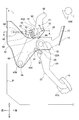
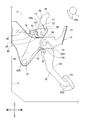
- the brake pedal device 1 of the first embodiment is made of metal and includes a pedal bracket 10, an operation pedal mechanism 20, a rotating member 50, a caulking pin 80, and the like. ..
- the pedal bracket 10 has a pair of side plates 12.
- the pair of side plates 12 face each other at predetermined intervals in the vehicle width direction, and are fixed to the dash panel P with bolts or the like.
- the dash panel P constitutes a part of the vehicle and is located on the front side of the vehicle with respect to the operation pedal mechanism 20.
- An operation pedal mechanism 20, a rotating member 50, a caulking pin 80, and the like are arranged between the pair of side plates 12.
- FIG. 1 of the pair of side plates 12, the side plate 12 on the left side in the vehicle width direction is shown, and the side plate 12 on the right side in the vehicle width direction is not shown. This point is the same in FIGS. 3 to 5, 8 to 13, and 15 to 19 which will be described later.
- the operation pedal mechanism 20 is a so-called link type operation pedal mechanism, and includes an operation pedal 22, a link member 30, an intermediate lever 40, and the like.
- the operation pedal 22 is rotatably supported with respect to the pedal bracket 10 by an operation shaft portion 16 arranged at the upper end portion 22A thereof.
- a tread 24 is provided on the lower end 22B of the operation pedal 22.
- the tread portion 24 is rotatable with respect to the pedal bracket 10 and can be stepped on the front side of the vehicle by the driver of the vehicle.
- the vehicle is controlled according to the amount of operation (pedal stroke, pedaling force, etc.) by stepping on the tread 24.
- the vehicle control performed by stepping on the tread 24 in this way is referred to as a stepping operation on the tread 24 of the operation pedal mechanism 20.
- the intermediate lever 40 is rotatably supported by the intermediate shaft portion 18 arranged at the lower end portion 40B thereof with respect to the pedal bracket 10.
- a rotating shaft portion 14 and a caulking pin 80 are arranged at the upper end portion 40A of the intermediate lever 40.
- the upper end portion 40A of the intermediate lever 40 is formed with an opening 42 on the front side of the vehicle with respect to the rotating shaft portion 14 and the caulking pin 80.
- the opening 42 is inclined so as to be directed toward the lower side of the vehicle toward the rear side of the vehicle.
- the intermediate portion 40C of the intermediate lever 40 is connected to the operating pedal 22 by a link member 30 between the upper end portion 22A and the lower end portion 22B of the operating pedal 22.
- the link member 30 has a first link pin 32 and a second link pin 34.
- the first link pin 32 is arranged at the rear portion of the vehicle of the link member 30, and connects the link member 30 and the operation pedal 22.
- the second link pin 34 is arranged in the front portion of the vehicle of the link member 30, and connects the link member 30 and the intermediate lever 40.
- the rotating member 50 is a metal plate material and has an L-shape when viewed from the left side in the vehicle width direction.
- the rotating member 50 has a bent portion 52, a front end portion 54, and an upper end portion 56.
- the bent portion 52 of the rotating member 50 is a central portion of the rotating member 50, which is a bent portion of the rotating member 50.
- the above-mentioned rotating shaft portion 14 and caulking pin 80 are arranged in the bent portion 52.
- the rotating shaft portion 14 and the caulking pin 80 are crimped so as not to come off from the bent portion 52 of the rotating member 50 and the upper end portion 40A of the intermediate lever 40. As a result, the rotating shaft portion 14 and the caulking pin 80 fix the rotating member 50 to the intermediate lever 40.
- the strength of the caulking pin 80 is made smaller than the strength of the rotating shaft portion 14.
- the shear strength of the caulking pin 80 is made smaller than the shear strength of the rotating shaft portion 14 by making the shaft diameter of the caulking pin 80 smaller than the shaft diameter of the rotating shaft portion 14. ..
- the caulking pin 80 may be made of a material having a tensile strength lower than that of the material of the rotating shaft portion 14.
- breakage when the caulking pin 80 is deformed or deformed and broken (hereinafter referred to as “breakage”), the rotating member 50 and the intermediate lever 40 are released from being fixed by the caulking pin 80. It is possible to rotate with respect to the intermediate lever 40 about the rotation shaft portion 14.
- the rotary shaft portion 14 is provided with a step slightly larger than the plate thickness of the intermediate lever 40, so that the frictional resistance when the intermediate lever 40 rotates is reduced.
- the rotating member 50 is on the right side in the vehicle width direction and the intermediate lever 40 is on the left side in the vehicle width direction. However, unlike the first embodiment, the rotating member 50 is on the left side in the vehicle width direction and the intermediate lever 40 is on the vehicle width. It may be on the right side of the direction.
- the front end portion 54 of the rotating member 50 is a portion of the rotating member 50 extending from the bent portion 52 to the front side of the vehicle.
- the tip end portion 62 of the operating rod 60 is rotatably held via the connecting pin 70 and the clevis 72.
- a rotating shaft portion 14 and a caulking pin 80 are arranged in the vicinity of a line extending the axis 64 of the operating rod 60 from the connecting pin 70 to the rear side of the vehicle (hereinafter, referred to as “extension line of the axis 64 of the operating rod 60”). It is installed.
- the rotating shaft portion 14 is arranged slightly below the vehicle extension line of the axis line 64 of the operating rod 60.
- the caulking pin 80 is arranged on the upper side of the vehicle with respect to the extension line of the axis 64 of the operating rod 60.
- the rotating shaft portion 14 and the caulking pin 80 may be arranged on an extension line of the axis 64 of the operating rod 60.
- the operating rod 60 protrudes from the dash panel P to the rear side of the vehicle via a brake booster (not shown), and the protruding direction can be freely changed.
- the connecting pin 70 is in a state of being penetrated into the upper portion of the vehicle in the opening 42 formed in the upper end portion 40A of the intermediate lever 40, and the front end portion 54 of the rotating member 50 and the intermediate lever 40 are provided by a clip (not shown). It is prevented from coming off from the opening 42 of the upper end portion 40A and the clevis 72.
- the front end portion 54 of the rotating member 50 is provided with a protrusion 90 at a portion exposed from the opening 42 of the intermediate lever 40 when viewed from the left side in the vehicle width direction.
- the protrusion 90 projects to the left in the vehicle width direction.
- the protrusion 90 is arranged in the opening 42 of the intermediate lever 40 on the lower side of the vehicle with respect to the connecting pin 70 in a state of being separated from the opening edge of the opening 42.
- the protrusion 90 may be provided, for example, by press working, or may be provided by press-fitting a member other than the rotating member 50 into the rotating member 50.
- the upper end 56 of the rotating member 50 is a portion of the rotating member 50 extending upward from the bent portion 52 of the vehicle.
- On the rear side of the vehicle with respect to the upper end portion 56 there is a long instrument panel reinforcement I arranged in the longitudinal direction in the vehicle width direction. Therefore, the instrument panel reinforcement I is located on the rear side of the vehicle with respect to the dash panel P.
- the instrument panel reinforcement I constitutes a part of the vehicle, and has a collision bracket 200 and the like.
- the collision bracket 200 is fixed from the front end portion to the lower end portion of the instrument panel reinforcement I.
- the collision bracket 200 is arranged so as to abut against the upper end portion 56 of the rotating member 50 at the time of a vehicle collision.
- a contact surface portion for contacting the upper end portion 56 of the rotating member 50 is provided so that the rotating member 50 can be easily displaced toward the front side of the vehicle.
- the upper end portion 56 extends from the axis 64 of the operating rod 60 in a direction in which the instrument panel reinforcement I is located, and the portion that abuts the contact surface portion of the collision bracket 200 has a curved shape.
- the rotating shaft portion 14, the operating shaft portion 16, the intermediate shaft portion 18, the first link pin 32, the second link pin 34, the connecting pin 70, and the caulking pin 80 are substantially horizontal between the pair of side plates 12. It is arranged in a state substantially parallel to the vehicle width direction.
- the intermediate lever 40 rotates in a predetermined direction (counterclockwise direction in FIG. 1) around the intermediate shaft portion 18 as the operation pedal 22 rotates. Therefore, the rotating member 50 and the operating rod 60 are displaced toward the front side of the vehicle.
- the operating rod 60 controls the operating force at the time of stepping on the driving state of the vehicle through a hydraulic circuit, an electronic circuit, or the like. Communicate to the device or control device. In this way, the stepping operation on the step portion 24 of the operation pedal mechanism 20 is performed.
- the reaction force from the operating rod 60 acts on the rotating member 50 via the connecting pin 70, and the caulking pin 80 is deviated from the extension line of the axis 64 of the operating rod 60.
- the load acts.
- the load that acts on the caulking pin 80 by transmitting the reaction force from the operating rod 60 to the caulking pin 80 via the connecting pin 70 and the rotating member 50 is called a fixed load.
- Reference numeral F1 indicates a fixed load.
- the caulking pin 80 When the tread 24 is stepped on the front side of the vehicle by the operating load of the driver, when the tread 24 is further stepped on the front side of the vehicle and the operating load acting on the tread 24 is increased, the caulking pin is used.
- the fixed load acting on 80 also increases. Therefore, the fixed load acting on the caulking pin 80 when the tread portion 24 is stepped on to the front side of the vehicle to the maximum and the operating load is the maximum in design is defined as the first load.
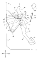
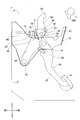
- the caulking pin 80 is broken by the impact load, so that the caulking pin 80 comes off from the rotating member 50 and the intermediate lever 40. As a result, the rotating member 50 and the intermediate lever 40 are released from being fixed by the caulking pin 80.
- the rotating member 50 is pushed out to the front side of the vehicle by the collision bracket 200, so that the upper end portion 56 of the rotating member 50 is on the front side of the vehicle centering on the rotating shaft portion 14 (FIG. 3).
- the front end portion 54 of the rotating member 50 and the tip end portion 62 of the operating rod 60 are displaced downward on the vehicle via the connecting pin 70 and the clevis 72.
- the tread portion 24 of the operation pedal 22 is displaced toward the front side of the vehicle.
- the rotating member 50 and the caulking pin 80 are added to the so-called link type operation pedal mechanism 20, so that the operation pedal mechanism 20 at the time of a vehicle collision
- the tread portion 24 is prevented from retreating.
- Reference numerals 82 and 84 indicate mounting holes for inserting the caulking pin 80.
- the mounting hole 82 is provided in the upper end portion 40A of the intermediate lever 40, and is formed in a round hole into which the caulking pin 80 can be inserted.
- the mounting hole 84 is provided in the bent portion 52 of the rotating member 50, and is formed in an elongated hole through which the caulking pin 80 can penetrate. Due to such a difference in hole shape, the misalignment that occurs between the mounting hole 82 and the mounting hole 84 is absorbed.
- the mounting hole 82 provided in the upper end portion 40A of the intermediate lever 40 is a long hole
- the mounting hole 84 provided in the bent portion 52 of the rotating member 50 is a round hole. May be good.
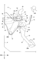
- the tread 24 represented by the alternate long and short dash line indicates the position of the tread 24 when the stepping operation on the tread 24 of the operation pedal mechanism 20 is released.
- the upper end portion 56 of the rotating member 50 rotates around the rotating shaft portion 14 toward the rear side of the vehicle (clockwise in FIG. 3), and at the same time, the front end portion 54 of the rotating member 50 and the operating member. Even if the tip 62 of the rod 60 is displaced upward on the vehicle via the connecting pin 70 and the clevis 72, it is possible to prevent the tread 24 of the operation pedal mechanism 20 from retreating in the event of a vehicle collision.
- the rotating member 50 rotates in a predetermined direction (counterclockwise direction in FIG. 4) about the intermediate shaft portion 18. It is integrated with the intermediate lever 40 and displaced toward the front side of the vehicle. As a result, the front end portion 54 of the rotating member 50 and the tip end portion 62 of the operating rod 60 are displaced toward the front side of the vehicle via the connecting pin 70 and the clevis 72. Therefore, the stepping operation on the step portion 24 of the operation pedal mechanism 20 becomes possible.
- a load acting on the protrusion 90 is referred to as a restraining load F2.
- the point of action D of the restraining load F2 (that is, the position where the protrusion 90 comes into pressure contact with the opening edge of the opening 42 of the intermediate lever 40) is the rotation member 50 centered on the rotation shaft portion 14. It is isolated from the opening edge (, the rotating member 50, the connecting pin 70, etc.) of the opening 42 of the intermediate lever 40 in the operation pedal mechanism 20 until the suppression of rotation is started.
- the strength of the protrusion 90 is made smaller than the strength of the caulking pin 80.
- the shaft diameter of the protrusion 90 is made smaller than the shaft diameter of the caulking pin 80, so that the shear strength of the protrusion 90 is made smaller than the shear strength of the caulking pin 80.
- the protrusion 90 may be made of a material having a tensile strength lower than that of the caulking pin 80. As a result, if the caulking pin 80 is broken at the time of a vehicle collision, the protrusion 90 is deformed by shearing or bending. Therefore, the protrusion 90 does not prevent the step portion 24 of the operation pedal mechanism 20 from retreating in the event of a vehicle collision.
- the strength of the protrusion 90 may be higher than the strength of the caulking pin 80 as long as it does not prevent the step portion 24 of the operation pedal mechanism 20 from retreating in the event of a vehicle collision.
- the tread portion 24 is the driver's step. It is stepped on the front side of the vehicle by the operating load. Further, when the tread 24 is stepped on the front side of the vehicle and the operating load acting on the tread 24 becomes large, the restraining load F2 acting on the protrusion 90 also becomes large. Therefore, the restraining load F2 that acts on the protrusion 90 when the tread 24 is maximally stepped on the front side of the vehicle and the operating load is the maximum in design is defined as the second load.
- the protrusion 90 When the restraining load F2 exceeds the second reference load larger than the second load, the protrusion 90 is deformed by shearing or bending due to the restraining load F2, so that the rotating member 50 rotates around the rotating shaft portion 14. Deterrence is released. Therefore, the rotation of the rotating member 50 about the rotating shaft portion 14 is suppressed by the protruding portion 90 (that is, the caulking pin 80 is in a broken state for some reason, but the tread portion 24 of the operation pedal mechanism 20 If the restraining load F2 exceeds the second reference load due to the collision bracket 200 of the instrument panel reinforcement I hitting the rotating member 50 even if the pedaling operation is changed from the normal time to the vehicle collision. , The tread portion 24 of the operation pedal mechanism 20 is prevented from retreating in the event of a vehicle collision.
- the pedal stroke in which the stepping operation on the step portion 24 of the operation pedal mechanism 20 is in an idle state can be adjusted by changing the position where the protrusion 90 protrudes from the upper end portion 56 of the rotating member 50. is there.
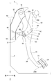
- the brake pedal device 2 of the second embodiment includes a claw portion 92 having the same mechanical properties as the protrusion 90, instead of the protrusion 90 of the first embodiment.
- the claw portion 92 projects from the lower edge of the rotating member 50 to the left side in the vehicle width direction at the bent portion 52 of the rotating member 50. Further, the claw portion 92 is arranged on the rear side of the vehicle with respect to the upper end portion 40A of the intermediate lever 40 in a state of being separated from the outer edge of the upper end portion 40A of the intermediate lever 40.
- the rotating member 50 when the rotating member 50 is rotated around the rotating shaft portion 14, as shown in FIG. 9, it protrudes from the edge of the bent portion 52 of the rotating member 50.
- the claw portion 92 abuts on the outer edge of the upper end portion 40A of the intermediate lever 40 (that is, the outer edge of the operation pedal mechanism 20), the rotation of the rotating member 50 around the rotating shaft portion 14 is suppressed.
- the restraining load F2 exceeds the second reference load larger than the second load, the restraining load F2 deforms the claw portion 92 by bending, and restraining the rotation of the rotating member 50 around the rotating shaft portion 14. Is released.
- the claw portion 92 has the same function as the protrusion 90 of the first embodiment.
- reference numeral 57 is a mounting hole provided in the bent portion 52 of the rotating member 50, and indicates a mounting hole formed in a round hole into which the rotating shaft portion 14 can be fitted.
- reference numeral 58 indicates a mounting hole provided in the front end portion 54 of the rotating member 50, which is formed in a round hole into which the connecting pin 70 can be fitted. It should be noted that these mounting holes 57 and 58 are similarly provided in other embodiments.
- the brake pedal device 3 of the third embodiment includes a protrusion 94 having the same mechanical properties as the protrusion 90, instead of the protrusion 90 of the first embodiment.
- the projecting piece portion 94 extends inward from the opening edge of the opening 42 of the intermediate lever 40 of the operation pedal mechanism 20. Further, the projecting piece portion 94 is arranged on the vehicle lower side of the connecting pin 70 in the opening 42 of the intermediate lever 40 in a state of being separated from the connecting pin 70.
- the rotating member 50 when the rotating member 50 is rotated around the rotating shaft portion 14, it extends from the opening edge of the opening 42 of the intermediate lever 40 as shown in FIG.
- the connecting pin 70 fitted into the rotating member 50 abuts against the protruding piece portion 94, so that the rotation of the rotating member 50 around the rotating shaft portion 14 is suppressed.
- the thrusting piece portion 94 when the restraining load F2 exceeds the second reference load larger than the second load, the thrusting piece portion 94 is deformed by bending due to the restraining load F2, and the rotating member 50 rotates around the rotating shaft portion 14. The deterrence is released.
- the projecting piece portion 94 has the same function as the protruding portion 90 of the first embodiment.
- FIGS. 13 to 16 correspond to FIGS. 1 to 4 of the first embodiment.
- the same reference numerals will be given to the parts substantially in common with the first embodiment, and detailed description thereof will be omitted.
- the brake pedal device 4 of the fourth embodiment includes a suppression pin 96 having the same mechanical properties as the protrusion 90, instead of the protrusion 90 of the first embodiment.
- the restraint pin 96 is attached to the rotating member 50 and the intermediate lever 40 of the operation pedal mechanism 20 in a state of being penetrated by caulking on the upper side of the vehicle with respect to the rotating shaft portion 14.
- Reference numerals 44 and 59 indicate mounting holes for inserting the suppression pin 96.
- the mounting hole 44 is provided in the upper end portion 40A of the intermediate lever 40, and is formed in an elongated hole through which the restraint pin 96 can penetrate.
- the mounting hole 59 is provided in the bent portion 52 of the rotating member 50, and is formed in a round hole into which the restraining pin 96 can be inserted. As a result, the misalignment that occurs between the mounting hole 44 and the mounting hole 59 is absorbed.
- the restraint pin 96 is arranged in the rear portion of the vehicle among the mounting holes 44 of the intermediate lever 40, but forms the mounting holes 44 of the intermediate lever 40. It is in a state of being separated from the opening edge.
- the restraint pin 96 in the brake pedal device 4 of the fourth embodiment, when the rotating member 50 is rotated around the rotating shaft portion 14, as shown in FIG. 16, among the mounting holes 44 of the intermediate lever 40, the front of the vehicle The restraint pin 96 fitted into the rotary member 50 abuts against the opening edge forming the portion, so that the rotation of the rotary member 50 around the rotary shaft portion 14 is restrained. Further, when the restraint load F2 exceeds the second reference load larger than the second load, the restraint pin 96 is deformed or deformed and broken by the restraint load F2 (hereinafter, referred to as “breakage”). The restraint of rotation of the rotating member 50 around the rotating shaft portion 14 is released. In this way, the restraint pin 96 has the same function as the protrusion 90 of the first embodiment.
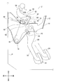
- the operation pedal mechanism 20 does not include the link member 30 and the intermediate lever 40 of the first embodiment. Therefore, the rotating shaft portion 14 and the caulking pin 80 fix the obtuse-angled V-shaped rotating member 50 to the operation pedal 22. As a result, the rotating shaft portion 14 and the caulking pin 80 are arranged on the axis 64 of the operating rod 60 between the upper end portion 22A and the lower end portion 22B of the operation pedal 22.
- the opening 26 is formed in the operation pedal 22 of the operation pedal mechanism 20 instead of the opening 42 of the first embodiment. Further, the protrusion 90 is arranged in the opening 26 of the operation pedal 22 in a state of being separated from the opening edge of the opening 26 by protruding to the right in the vehicle width direction at the front end 54 of the rotating member 50. It is installed.
- the rotating member 50 and the caulking pin 80 are added to the operation pedal mechanism 20. It is possible to prevent the tread portion 24 of the operation pedal mechanism 20 from retreating in the event of a vehicle collision, and even if the caulking pin 80 is broken due to some factor in normal times, the protrusion 90, the claw portion 92, By suppressing the rotation of the rotating member 50 around the rotating shaft portion 14 by the projecting piece portion 94 or the restraining pin 96, the stepping operation on the step portion 24 of the operation pedal mechanism 20 is enabled.
- a restraining load F2 acting on the protrusion 90, the claw 92, the projecting piece 94, or the restraining pin 96 as the rotation of the rotating member 50 around the rotating shaft 14 is restrained, and the tread 24 is in front of the vehicle. If the second reference load, which is larger than the second load when the vehicle is fully depressed to the side, is exceeded, the protrusion 90, the claw 92, or the projecting piece 94 is deformed, or the restraint pin 96 is broken, and the rotating shaft The restraint of rotation of the rotating member 50 centered on the portion 14 is released.
- the stepping operation on the step portion 24 of the operation pedal mechanism 20 is possible until the tread portion 24 is fully depressed toward the front side of the vehicle.
- the suppression of the rotation of the rotating member 50 centered on the rotating shaft portion 14 is released, and the tread portion 24 of the operation pedal mechanism 20 is prevented from retreating in the event of a vehicle collision. It is possible to do it again.
- the protrusion 90, the claw portion 92, or the projecting piece portion 94 is It is formed on the rotating member 50, and is centered on the rotating shaft portion 14 by being pressed against the opening edge of the opening 42 of the intermediate lever 40 in the operation pedal mechanism 20, the outer edge of the intermediate lever 40, or the connecting pin 70.
- a restraining load F2 accompanying the restraining of rotation of the rotating member 50 is applied to the protrusion 90, the claw 92, or the projecting piece 94.
- the tread portion 24 of the operation pedal mechanism 20 at the time of a vehicle collision is realized by a simple configuration.
- the restraint pin 96 is penetrated through the intermediate lever 40 of the rotating member 50 and the operation pedal mechanism 20 to rotate the rotating member 50 around the rotating shaft portion 14.
- the restraint load F2 accompanying the restraint of the above is applied to the restraint pin 96.
- the action point D of the restraint load F2 of the protrusion 90, the claw portion 92, the projecting piece portion 94, or the restraint pin 96 is the rotation shaft portion. Installation of the opening edge of the opening 42 of the intermediate lever 40 in the operation pedal mechanism 20, the outer edge of the intermediate lever 40, the connecting pin 70, and the intermediate lever 40 until the suppression of the rotation of the rotating member 50 centered on 14 is started. It is isolated from the opening edge forming the hole 44.
- the operating pedal mechanism at the time of a vehicle collision is provided by the protrusion 90 provided on the rotating member 50 and the opening 42 provided on the intermediate lever 40 of the operating pedal mechanism 20. It is easy to manufacture because it realizes a fail-safe function for preventing the treads 24 of 20 from retreating.
- the brake pedal device 2 of the second embodiment is manufactured because the claw portion 92 provided on the rotating member 50 realizes a fail-safe function for preventing the tread portion 24 of the operation pedal mechanism 20 from retreating in the event of a vehicle collision. Is easy.
- the connecting pin 70 is caught by the projecting piece portion 94 in the opening 42 of the intermediate lever 40, so that the rotating member 50 rotates around the rotating shaft portion 14. It is stopped and the tip 62 of the operating rod 60 is pushed toward the front side of the vehicle. Therefore, in the brake pedal device 3 of the third embodiment, in the intermediate lever 40 of the operation pedal mechanism 20, the connecting pin 70 penetrating the opening 42 and the projecting piece portion 94 extending from the opening edge of the opening 42 are used. Since the fail-safe function for preventing the tread portion 24 of the operation pedal mechanism 20 from retreating in the event of a vehicle collision is realized, the manufacturing is easy.
- the brake pedal devices 1, 2, 3, 4, and 5 are examples of "vehicle operation pedal devices”.
- the pedal bracket 10 is an example of a “support member”.
- the operating rod 60 is an example of a "vehicle control mechanism”.
- the tip 62 of the operating rod 60 is an example of an “input unit of a vehicle control mechanism”.
- the connecting pin 70 is an example of a “connecting portion”.
- the dash panel P is an example of the “first vehicle component”.
- the instrument panel reinforcement I and the collision bracket 200 are examples of the “second vehicle component”.
- the caulking pin 80 is an example of a "fixing member”.
- the protrusion 90 of the first embodiment and the fifth embodiment is an example of the "operation holding mechanism”.
- the claw portion 92 of the second embodiment is an example of the “operation holding mechanism”.
- the projecting piece portion 94 of the third embodiment is an example of the “operation holding mechanism”.
- the suppression pin 96 of the fourth embodiment is an example of the “operation holding mechanism”.
- the point of action D of the restraint load F2 is an example of "a place where the restraint load acts".
- the protrusion 90 is attached to the rotating member 50 so as to be separated from the outer edge of the upper end 40A of the intermediate lever 40 on the outer side of the upper end 40A of the intermediate lever 40. It may be provided so that the rotation of the rotating member 50 about the rotating shaft portion 14 is suppressed.
- the protrusion 90 is provided on the upper end 40A of the intermediate lever 40, and is arranged on the outer side of the bent portion 52 or the front end 54 of the rotating member 50 in a state of being separated from the outer edge of the rotating member 50. By doing so, the rotation of the rotating member 50 around the rotating shaft portion 14 may be suppressed.
- the claw portion 92 is in a state of being separated from the outer edge of the upper end portion 40A of the intermediate lever 40 on the vehicle front side or the vehicle upper side side of the upper end portion 40A of the intermediate lever 40.
- the rotating member 50 may be provided, whereby the rotation of the rotating member 50 around the rotating shaft portion 14 may be suppressed.
- the claw portion 92 is provided at the upper end portion 40A of the intermediate lever 40, and is arranged on the outer side of the bent portion 52 or the front end portion 54 of the rotating member 50 in a state of being separated from the outer edge of the rotating member 50. By doing so, the rotation of the rotating member 50 around the rotating shaft portion 14 may be suppressed.
- the caulking pin 80 when the caulking pin 80 is in a broken state due to some factor in the normal state, when the tread portion 24 is stepped on the front side of the vehicle by the driver, the upper end portion 56 of the rotating member 50 is pressed. Although it rotates to the front side of the vehicle about the rotation shaft portion 14, it may rotate to the rear side of the vehicle.
- the connecting pin 70 in the normal state penetrates into the lower portion of the vehicle in the opening 42 of the intermediate lever 40.
- the connecting pin 70 into which the rotating member 50 is fitted does not have to penetrate the opening 42 of the intermediate lever 40.
- the connecting pin 70 may be fitted through the front end portion 54 of the rotating member 50 arranged on the front side of the vehicle with respect to the upper end portion 40A of the intermediate lever 40.
- the caulking pin 80 is displaced upward, but downward.
- the present invention can be applied even if it is displaced to the side.
- the present invention is applied with the operation pedal 22 as a brake pedal, but the present invention may be applied as each pedal (for example, an accelerator pedal or a clutch pedal) used in a vehicle.
- the parts of the brake pedal devices 1, 2, 3, 4, and 5 of each embodiment are not limited to metal, and may be made of resin.
- 1,2,3,4,5 Brake pedal device (vehicle operation pedal device) 10 Pedal bracket (support member) 14 Rotating shaft 20 Operating pedal mechanism 24 Step 42 Opening 50 Rotating member 52 Bent 54 Front end 56 Upper end 60 Operating rod (Vehicle control mechanism) 62 Tip (input) 70 Connecting pin (connecting part) 80 caulking pin (fixing member) 90 Protrusion (operation holding mechanism) 92 Claw (operation holding mechanism) 94 Projection holding mechanism (operation holding mechanism) 96 Suppression pin (operation holding mechanism) 200 Collision bracket (second vehicle component) D Point of action of restraint load (location where restraint load acts) F1 Fixed load / Impact load F2 Suppression load P Dash panel (1st vehicle component) I Instrument panel reinforcement (second vehicle component)
Landscapes
- Engineering & Computer Science (AREA)
- Physics & Mathematics (AREA)
- General Physics & Mathematics (AREA)
- Automation & Control Theory (AREA)
- Mechanical Engineering (AREA)
- Transportation (AREA)
- Mechanical Control Devices (AREA)
- Braking Elements And Transmission Devices (AREA)
Abstract
Dispositif de pédale d'actionnement qui est destiné à des véhicules et qui est pourvu d'une fonction de sécurité intégrée pour empêcher le retrait d'une partie semelle d'une pédale d'actionnement pendant une collision de véhicule. Un dispositif de pédale de frein (1) est pourvu d'une partie saillie (90) qui permet une prévention de rotation pour empêcher un organe rotatif (50) de tourner autour d'une partie arbre rotatif (14) et reçoit une charge de suppression (F2) par l'intermédiaire de la prévention de rotation. Dans la partie saillante (90), une seconde charge agit en tant que charge de suppression (F2) lorsqu'une partie semelle (24) du mécanisme de pédale d'actionnement (20) est appuyée au maximum vers le côté avant du véhicule pendant la prévention de rotation, et lorsque la charge de suppression (F2) dépasse la seconde charge, la prévention de rotation est libérée par cisaillement ou flexion de la partie saillante (90).
Priority Applications (3)
| Application Number | Priority Date | Filing Date | Title |
|---|---|---|---|
| CN202080016945.6A CN113490899B (zh) | 2019-06-12 | 2020-04-13 | 车辆用操作踏板装置 |
| EP20823287.6A EP3985477A4 (fr) | 2019-06-12 | 2020-04-13 | Dispositif de pédale d'actionnement pour véhicule |
| US17/440,454 US11377078B2 (en) | 2019-06-12 | 2020-04-13 | Operative pedal device for vehicle |
Applications Claiming Priority (2)
| Application Number | Priority Date | Filing Date | Title |
|---|---|---|---|
| JP2019109662A JP7061985B2 (ja) | 2019-06-12 | 2019-06-12 | 車両用操作ペダル装置 |
| JP2019-109662 | 2019-06-12 |
Publications (1)
| Publication Number | Publication Date |
|---|---|
| WO2020250562A1 true WO2020250562A1 (fr) | 2020-12-17 |
Family
ID=73743467
Family Applications (1)
| Application Number | Title | Priority Date | Filing Date |
|---|---|---|---|
| PCT/JP2020/016310 WO2020250562A1 (fr) | 2019-06-12 | 2020-04-13 | Dispositif de pédale d'actionnement pour véhicule |
Country Status (5)
| Country | Link |
|---|---|
| US (1) | US11377078B2 (fr) |
| EP (1) | EP3985477A4 (fr) |
| JP (1) | JP7061985B2 (fr) |
| CN (1) | CN113490899B (fr) |
| WO (1) | WO2020250562A1 (fr) |
Families Citing this family (1)
| Publication number | Priority date | Publication date | Assignee | Title |
|---|---|---|---|---|
| JP7000300B2 (ja) * | 2018-12-11 | 2022-01-19 | 豊田鉄工株式会社 | 車両用操作ペダル装置 |
Citations (4)
| Publication number | Priority date | Publication date | Assignee | Title |
|---|---|---|---|---|
| JP2003146193A (ja) | 2001-08-29 | 2003-05-21 | Suzuki Motor Corp | ペダル支持構造 |
| JP2016139235A (ja) * | 2015-01-27 | 2016-08-04 | 豊田鉄工株式会社 | 車両用ペダル装置の後退防止装置 |
| JP2018200516A (ja) * | 2017-05-26 | 2018-12-20 | 豊田鉄工株式会社 | 車両用操作ペダル装置 |
| JP2019087190A (ja) * | 2017-11-10 | 2019-06-06 | 豊田鉄工株式会社 | 車両用操作ペダル装置 |
Family Cites Families (11)
| Publication number | Priority date | Publication date | Assignee | Title |
|---|---|---|---|---|
| FR2848959B1 (fr) * | 2002-12-20 | 2005-12-02 | Renault Sa | Dispositif de montage d'une pedale de vehicule automobile |
| US20070137398A1 (en) * | 2005-11-17 | 2007-06-21 | Mazda Motor Corporation | Support structure for control pedal |
| JP4764702B2 (ja) * | 2005-11-17 | 2011-09-07 | マツダ株式会社 | 操作ペダルの支持構造 |
| US20100089198A1 (en) * | 2006-12-27 | 2010-04-15 | Hiruta-Kogyo Co., Ltd. | Pedal device |
| JP6144636B2 (ja) * | 2014-01-31 | 2017-06-07 | 豊田鉄工株式会社 | 車両用ペダル装置の後退防止装置 |
| US9889826B2 (en) * | 2014-02-19 | 2018-02-13 | Ventra Group Co. | Variable ratio brake pedal |
| US9821777B2 (en) * | 2015-02-20 | 2017-11-21 | Toyota Jidosha Kabushiki Kaisha | Vehicle brake pedal device |
| WO2017208485A1 (fr) * | 2016-05-30 | 2017-12-07 | 豊田鉄工株式会社 | Dispositif de prévention de mouvement arrière pour dispositif de pédale de véhicule |
| SE541759C2 (en) * | 2017-06-22 | 2019-12-10 | Cj Automotive Ab | Pedal assembly with safety position for motor vehicle |
| JP2020030561A (ja) * | 2018-08-22 | 2020-02-27 | 豊田鉄工株式会社 | 車両用操作ペダル装置 |
| JP7000300B2 (ja) * | 2018-12-11 | 2022-01-19 | 豊田鉄工株式会社 | 車両用操作ペダル装置 |
-
2019
- 2019-06-12 JP JP2019109662A patent/JP7061985B2/ja active Active
-
2020
- 2020-04-13 CN CN202080016945.6A patent/CN113490899B/zh active Active
- 2020-04-13 EP EP20823287.6A patent/EP3985477A4/fr active Pending
- 2020-04-13 WO PCT/JP2020/016310 patent/WO2020250562A1/fr unknown
- 2020-04-13 US US17/440,454 patent/US11377078B2/en active Active
Patent Citations (4)
| Publication number | Priority date | Publication date | Assignee | Title |
|---|---|---|---|---|
| JP2003146193A (ja) | 2001-08-29 | 2003-05-21 | Suzuki Motor Corp | ペダル支持構造 |
| JP2016139235A (ja) * | 2015-01-27 | 2016-08-04 | 豊田鉄工株式会社 | 車両用ペダル装置の後退防止装置 |
| JP2018200516A (ja) * | 2017-05-26 | 2018-12-20 | 豊田鉄工株式会社 | 車両用操作ペダル装置 |
| JP2019087190A (ja) * | 2017-11-10 | 2019-06-06 | 豊田鉄工株式会社 | 車両用操作ペダル装置 |
Non-Patent Citations (1)
| Title |
|---|
| See also references of EP3985477A4 |
Also Published As
| Publication number | Publication date |
|---|---|
| JP2020201825A (ja) | 2020-12-17 |
| US11377078B2 (en) | 2022-07-05 |
| CN113490899B (zh) | 2022-06-10 |
| EP3985477A4 (fr) | 2023-06-07 |
| CN113490899A (zh) | 2021-10-08 |
| US20220144225A1 (en) | 2022-05-12 |
| EP3985477A1 (fr) | 2022-04-20 |
| JP7061985B2 (ja) | 2022-05-02 |
Similar Documents
| Publication | Publication Date | Title |
|---|---|---|
| EP1862363B1 (fr) | Appareil de pédale de frein pour un véhicule automobile | |
| JP5026696B2 (ja) | ブレーキペダルの緩衝装置 | |
| US9821777B2 (en) | Vehicle brake pedal device | |
| WO2020250562A1 (fr) | Dispositif de pédale d'actionnement pour véhicule | |
| JP5306937B2 (ja) | 自動車のブレーキペダル装置 | |
| CN111316190B (zh) | 车辆用操作踏板装置 | |
| JP3185164U (ja) | 自動車のペダル機構 | |
| JP7000300B2 (ja) | 車両用操作ペダル装置 | |
| JP2019053775A (ja) | 車両ペダル機構 | |
| JP5656113B2 (ja) | 車両のペダル装置 | |
| JP2000163147A (ja) | ペダルブラケットの構造 | |
| CN112424723B (zh) | 车辆用操作踏板装置 | |
| JP2011037377A (ja) | 自動車のブレーキペダル装置 | |
| WO2023238787A1 (fr) | Dispositif de pédale d'actionnement pour un véhicule | |
| JP3671668B2 (ja) | 車両用ペダル支持構造 | |
| JP2019016200A (ja) | 車両用操作ペダル装置 | |
| JP7000360B2 (ja) | 車両用操作ペダル装置 | |
| KR100986497B1 (ko) | 운전자 보호장치 | |
| WO2023058390A1 (fr) | Dispositif de pédale de commande pour véhicule | |
| JP2018200516A (ja) | 車両用操作ペダル装置 | |
| JP2020027382A (ja) | 車両用操作ペダル装置 | |
| KR20050110992A (ko) | 자동차의 브레이크 페달 |
Legal Events
| Date | Code | Title | Description |
|---|---|---|---|
| 121 | Ep: the epo has been informed by wipo that ep was designated in this application |
Ref document number: 20823287 Country of ref document: EP Kind code of ref document: A1 |
|
| NENP | Non-entry into the national phase |
Ref country code: DE |
|
| ENP | Entry into the national phase |
Ref document number: 2020823287 Country of ref document: EP Effective date: 20220112 |