WO2020250562A1 - Operative pedal device for vehicle - Google Patents
Operative pedal device for vehicle Download PDFInfo
- Publication number
- WO2020250562A1 WO2020250562A1 PCT/JP2020/016310 JP2020016310W WO2020250562A1 WO 2020250562 A1 WO2020250562 A1 WO 2020250562A1 JP 2020016310 W JP2020016310 W JP 2020016310W WO 2020250562 A1 WO2020250562 A1 WO 2020250562A1
- Authority
- WO
- WIPO (PCT)
- Prior art keywords
- vehicle
- rotating member
- load
- operation pedal
- restraint
- Prior art date
Links
Images


Classifications
-
- B—PERFORMING OPERATIONS; TRANSPORTING
- B60—VEHICLES IN GENERAL
- B60T—VEHICLE BRAKE CONTROL SYSTEMS OR PARTS THEREOF; BRAKE CONTROL SYSTEMS OR PARTS THEREOF, IN GENERAL; ARRANGEMENT OF BRAKING ELEMENTS ON VEHICLES IN GENERAL; PORTABLE DEVICES FOR PREVENTING UNWANTED MOVEMENT OF VEHICLES; VEHICLE MODIFICATIONS TO FACILITATE COOLING OF BRAKES
- B60T7/00—Brake-action initiating means
- B60T7/02—Brake-action initiating means for personal initiation
- B60T7/04—Brake-action initiating means for personal initiation foot actuated
- B60T7/06—Disposition of pedal
- B60T7/065—Disposition of pedal with means to prevent injuries in case of collision
-
- B—PERFORMING OPERATIONS; TRANSPORTING
- B60—VEHICLES IN GENERAL
- B60R—VEHICLES, VEHICLE FITTINGS, OR VEHICLE PARTS, NOT OTHERWISE PROVIDED FOR
- B60R21/00—Arrangements or fittings on vehicles for protecting or preventing injuries to occupants or pedestrians in case of accidents or other traffic risks
- B60R21/02—Occupant safety arrangements or fittings, e.g. crash pads
- B60R21/09—Control elements or operating handles movable from an operative to an out-of-the way position, e.g. pedals, switch knobs, window cranks
-
- G—PHYSICS
- G05—CONTROLLING; REGULATING
- G05G—CONTROL DEVICES OR SYSTEMS INSOFAR AS CHARACTERISED BY MECHANICAL FEATURES ONLY
- G05G1/00—Controlling members, e.g. knobs or handles; Assemblies or arrangements thereof; Indicating position of controlling members
- G05G1/30—Controlling members actuated by foot
- G05G1/32—Controlling members actuated by foot with means to prevent injury
- G05G1/323—Controlling members actuated by foot with means to prevent injury means disconnecting the connection between pedal and controlled member, e.g. by breaking or bending the connecting rod
-
- G—PHYSICS
- G05—CONTROLLING; REGULATING
- G05G—CONTROL DEVICES OR SYSTEMS INSOFAR AS CHARACTERISED BY MECHANICAL FEATURES ONLY
- G05G1/00—Controlling members, e.g. knobs or handles; Assemblies or arrangements thereof; Indicating position of controlling members
- G05G1/30—Controlling members actuated by foot
- G05G1/32—Controlling members actuated by foot with means to prevent injury
- G05G1/327—Controlling members actuated by foot with means to prevent injury means disconnecting the pedal from its hinge or support, e.g. by breaking or bending the support
-
- G—PHYSICS
- G05—CONTROLLING; REGULATING
- G05G—CONTROL DEVICES OR SYSTEMS INSOFAR AS CHARACTERISED BY MECHANICAL FEATURES ONLY
- G05G1/00—Controlling members, e.g. knobs or handles; Assemblies or arrangements thereof; Indicating position of controlling members
- G05G1/30—Controlling members actuated by foot
- G05G1/44—Controlling members actuated by foot pivoting
Definitions
- the present invention suppresses the tread of the operation pedal mechanism from retreating to the rear side of the vehicle when the vehicle component is displaced to the rear side of the vehicle due to a vehicle collision (hereinafter, "the operation pedal mechanism at the time of a vehicle collision”. It is called “prevention of backward movement of the tread”.) It relates to an operation pedal device for a vehicle.
- Patent Document 1 supports a pedal hanger mounted on a vehicle body with an upper end of a pedal arm via a pedal shaft, and a master cylinder installed in the engine room in the middle of the pedal arm.
- one end of the first link is pivotally supported in the middle of the pedal arm, and the other end of the first link is attached to the pedal shaft.
- the push rod is connected to an intermediate position of the first link, and the pedal hanger is attached to the vehicle body attachment portion due to an excessive input load from the front of the vehicle body.
- the engaging portion at the other end of the second link is configured to be detachable from the pedal shaft when it moves relative to the side.
- the pedal arm in the normal state, can be operated independently of the link mechanism, and when an excessive impact load from the front of the vehicle body is applied, the pedal arm can be rotated to the front of the vehicle body via the link mechanism. it can. Therefore, the operation can be reliably performed without complicating the mechanism.
- an object of the present invention is to provide a vehicle operation pedal device having a fail-safe function for preventing the tread of the operation pedal mechanism from retreating in the event of a vehicle collision. To do.
- the invention according to claim 1 made to solve this problem is a vehicle operation pedal device, which is provided on a support member fixed to a first vehicle component member and a support member provided on the support member.
- An operation pedal mechanism having a rotatable tread that allows the tread to be stepped on the front side of the vehicle, a bent part, a front end portion that extends from the bent part to the front side of the vehicle, and an upward extension from the bent part.
- a rotating member having an upper end portion that is rotatably supported by a rotating shaft portion at a bending portion with respect to an operation pedal mechanism, and a front end portion of the rotating member that protrudes from the first vehicle component member to the rear side of the vehicle.
- the rotating member and the operating pedal mechanism are fixed at the connecting portion that rotatably holds the input portion of the vehicle control mechanism with respect to the rotating member and the bent portion of the rotating member, and the step portion of the operating pedal mechanism is the vehicle. It is equipped with a fixing member on which the first load acts when the vehicle is fully depressed to the front side, and the amount of operation due to the depression of the step portion is transmitted to the vehicle control mechanism via the rotating member and the connecting portion, and the first vehicle.
- the constituent member is displaced to the rear side of the vehicle at the time of a vehicle collision, the upper end portion of the rotating member comes into contact with the second vehicle constituent member arranged on the rear side of the vehicle with respect to the first vehicle constituent member, thereby forming the fixed member.
- the second load acts as a deterrent load
- the operation holding mechanism is deformed. It is characterized by releasing the rotation restraint.
- the invention according to claim 2 is the operation pedal device for a vehicle according to claim 1, wherein the operation holding mechanism is formed on the operation pedal mechanism or the rotating member, and is connected to the operation pedal mechanism, the rotating member, or the connecting portion. It is characterized in that a restraining load is applied to the operation holding mechanism by pressure welding.
- the invention according to claim 3 is the vehicle operation pedal device according to claim 1, wherein the operation holding mechanism is a restraint pin penetrating the rotating member and the operation pedal mechanism.
- the invention according to claim 4 is the vehicle operation pedal device according to claim 2 or 3, wherein in the operation holding mechanism, a portion where a restraining load acts is an operation pedal until rotation restraint is started. It is characterized by being isolated from the mechanism, the rotating member, and the connecting portion.
- the invention according to claim 5 is the operation pedal device for a vehicle according to claim 1, wherein the operation holding mechanism is a protrusion formed in an opening formed in the operation pedal mechanism so as to project from a rotating member.
- the operation holding mechanism is a protrusion formed in an opening formed in the operation pedal mechanism so as to project from a rotating member.
- the invention according to claim 6 is the operation pedal device for a vehicle according to claim 1.
- the operation holding mechanism is a claw portion protruding from an edge of a rotating member, and the claw portion is an operation pedal mechanism.
- the invention according to claim 7 is the vehicle operation pedal device according to claim 1, wherein the connecting portion is penetrated into an opening formed in the operation pedal mechanism, and the operation holding mechanism is an opening edge of the opening. It is a projecting piece that extends inward from the opening, and when the connecting part abuts, the projecting piece suppresses rotation and applies a deterrent load to the projecting piece, and the deterrent load is the second load. It is characterized in that it deforms when it becomes larger than that and releases the rotation restraint.
- the vehicle operation pedal device of the present invention has a fail-safe function to prevent the tread of the operation pedal mechanism from retreating in the event of a vehicle collision.
- the front-back direction, the up-down direction, and the left-right direction are as described in each figure.
- the back side of the paper surface of the drawing is the right direction, and the front side of the paper surface of the drawing is the left direction.
- the back side of the paper surface of the drawing is upward, and the front side of the paper surface of the drawing is downward.
- the front direction is described as “vehicle front side”
- the rear direction is described as “vehicle rear side”
- the upward direction is described as “vehicle upper side”
- the downward direction is described as “vehicle lower side”.
- the left-right direction is described as "vehicle width direction”.
- the brake pedal device 1 of the first embodiment is made of metal and includes a pedal bracket 10, an operation pedal mechanism 20, a rotating member 50, a caulking pin 80, and the like. ..
- the pedal bracket 10 has a pair of side plates 12.
- the pair of side plates 12 face each other at predetermined intervals in the vehicle width direction, and are fixed to the dash panel P with bolts or the like.
- the dash panel P constitutes a part of the vehicle and is located on the front side of the vehicle with respect to the operation pedal mechanism 20.
- An operation pedal mechanism 20, a rotating member 50, a caulking pin 80, and the like are arranged between the pair of side plates 12.
- FIG. 1 of the pair of side plates 12, the side plate 12 on the left side in the vehicle width direction is shown, and the side plate 12 on the right side in the vehicle width direction is not shown. This point is the same in FIGS. 3 to 5, 8 to 13, and 15 to 19 which will be described later.
- the operation pedal mechanism 20 is a so-called link type operation pedal mechanism, and includes an operation pedal 22, a link member 30, an intermediate lever 40, and the like.
- the operation pedal 22 is rotatably supported with respect to the pedal bracket 10 by an operation shaft portion 16 arranged at the upper end portion 22A thereof.
- a tread 24 is provided on the lower end 22B of the operation pedal 22.
- the tread portion 24 is rotatable with respect to the pedal bracket 10 and can be stepped on the front side of the vehicle by the driver of the vehicle.
- the vehicle is controlled according to the amount of operation (pedal stroke, pedaling force, etc.) by stepping on the tread 24.
- the vehicle control performed by stepping on the tread 24 in this way is referred to as a stepping operation on the tread 24 of the operation pedal mechanism 20.
- the intermediate lever 40 is rotatably supported by the intermediate shaft portion 18 arranged at the lower end portion 40B thereof with respect to the pedal bracket 10.
- a rotating shaft portion 14 and a caulking pin 80 are arranged at the upper end portion 40A of the intermediate lever 40.
- the upper end portion 40A of the intermediate lever 40 is formed with an opening 42 on the front side of the vehicle with respect to the rotating shaft portion 14 and the caulking pin 80.
- the opening 42 is inclined so as to be directed toward the lower side of the vehicle toward the rear side of the vehicle.
- the intermediate portion 40C of the intermediate lever 40 is connected to the operating pedal 22 by a link member 30 between the upper end portion 22A and the lower end portion 22B of the operating pedal 22.
- the link member 30 has a first link pin 32 and a second link pin 34.
- the first link pin 32 is arranged at the rear portion of the vehicle of the link member 30, and connects the link member 30 and the operation pedal 22.
- the second link pin 34 is arranged in the front portion of the vehicle of the link member 30, and connects the link member 30 and the intermediate lever 40.
- the rotating member 50 is a metal plate material and has an L-shape when viewed from the left side in the vehicle width direction.
- the rotating member 50 has a bent portion 52, a front end portion 54, and an upper end portion 56.
- the bent portion 52 of the rotating member 50 is a central portion of the rotating member 50, which is a bent portion of the rotating member 50.
- the above-mentioned rotating shaft portion 14 and caulking pin 80 are arranged in the bent portion 52.
- the rotating shaft portion 14 and the caulking pin 80 are crimped so as not to come off from the bent portion 52 of the rotating member 50 and the upper end portion 40A of the intermediate lever 40. As a result, the rotating shaft portion 14 and the caulking pin 80 fix the rotating member 50 to the intermediate lever 40.
- the strength of the caulking pin 80 is made smaller than the strength of the rotating shaft portion 14.
- the shear strength of the caulking pin 80 is made smaller than the shear strength of the rotating shaft portion 14 by making the shaft diameter of the caulking pin 80 smaller than the shaft diameter of the rotating shaft portion 14. ..
- the caulking pin 80 may be made of a material having a tensile strength lower than that of the material of the rotating shaft portion 14.
- breakage when the caulking pin 80 is deformed or deformed and broken (hereinafter referred to as “breakage”), the rotating member 50 and the intermediate lever 40 are released from being fixed by the caulking pin 80. It is possible to rotate with respect to the intermediate lever 40 about the rotation shaft portion 14.
- the rotary shaft portion 14 is provided with a step slightly larger than the plate thickness of the intermediate lever 40, so that the frictional resistance when the intermediate lever 40 rotates is reduced.
- the rotating member 50 is on the right side in the vehicle width direction and the intermediate lever 40 is on the left side in the vehicle width direction. However, unlike the first embodiment, the rotating member 50 is on the left side in the vehicle width direction and the intermediate lever 40 is on the vehicle width. It may be on the right side of the direction.
- the front end portion 54 of the rotating member 50 is a portion of the rotating member 50 extending from the bent portion 52 to the front side of the vehicle.
- the tip end portion 62 of the operating rod 60 is rotatably held via the connecting pin 70 and the clevis 72.
- a rotating shaft portion 14 and a caulking pin 80 are arranged in the vicinity of a line extending the axis 64 of the operating rod 60 from the connecting pin 70 to the rear side of the vehicle (hereinafter, referred to as “extension line of the axis 64 of the operating rod 60”). It is installed.
- the rotating shaft portion 14 is arranged slightly below the vehicle extension line of the axis line 64 of the operating rod 60.
- the caulking pin 80 is arranged on the upper side of the vehicle with respect to the extension line of the axis 64 of the operating rod 60.
- the rotating shaft portion 14 and the caulking pin 80 may be arranged on an extension line of the axis 64 of the operating rod 60.
- the operating rod 60 protrudes from the dash panel P to the rear side of the vehicle via a brake booster (not shown), and the protruding direction can be freely changed.
- the connecting pin 70 is in a state of being penetrated into the upper portion of the vehicle in the opening 42 formed in the upper end portion 40A of the intermediate lever 40, and the front end portion 54 of the rotating member 50 and the intermediate lever 40 are provided by a clip (not shown). It is prevented from coming off from the opening 42 of the upper end portion 40A and the clevis 72.
- the front end portion 54 of the rotating member 50 is provided with a protrusion 90 at a portion exposed from the opening 42 of the intermediate lever 40 when viewed from the left side in the vehicle width direction.
- the protrusion 90 projects to the left in the vehicle width direction.
- the protrusion 90 is arranged in the opening 42 of the intermediate lever 40 on the lower side of the vehicle with respect to the connecting pin 70 in a state of being separated from the opening edge of the opening 42.
- the protrusion 90 may be provided, for example, by press working, or may be provided by press-fitting a member other than the rotating member 50 into the rotating member 50.
- the upper end 56 of the rotating member 50 is a portion of the rotating member 50 extending upward from the bent portion 52 of the vehicle.
- On the rear side of the vehicle with respect to the upper end portion 56 there is a long instrument panel reinforcement I arranged in the longitudinal direction in the vehicle width direction. Therefore, the instrument panel reinforcement I is located on the rear side of the vehicle with respect to the dash panel P.
- the instrument panel reinforcement I constitutes a part of the vehicle, and has a collision bracket 200 and the like.
- the collision bracket 200 is fixed from the front end portion to the lower end portion of the instrument panel reinforcement I.
- the collision bracket 200 is arranged so as to abut against the upper end portion 56 of the rotating member 50 at the time of a vehicle collision.
- a contact surface portion for contacting the upper end portion 56 of the rotating member 50 is provided so that the rotating member 50 can be easily displaced toward the front side of the vehicle.
- the upper end portion 56 extends from the axis 64 of the operating rod 60 in a direction in which the instrument panel reinforcement I is located, and the portion that abuts the contact surface portion of the collision bracket 200 has a curved shape.
- the rotating shaft portion 14, the operating shaft portion 16, the intermediate shaft portion 18, the first link pin 32, the second link pin 34, the connecting pin 70, and the caulking pin 80 are substantially horizontal between the pair of side plates 12. It is arranged in a state substantially parallel to the vehicle width direction.
- the intermediate lever 40 rotates in a predetermined direction (counterclockwise direction in FIG. 1) around the intermediate shaft portion 18 as the operation pedal 22 rotates. Therefore, the rotating member 50 and the operating rod 60 are displaced toward the front side of the vehicle.
- the operating rod 60 controls the operating force at the time of stepping on the driving state of the vehicle through a hydraulic circuit, an electronic circuit, or the like. Communicate to the device or control device. In this way, the stepping operation on the step portion 24 of the operation pedal mechanism 20 is performed.
- the reaction force from the operating rod 60 acts on the rotating member 50 via the connecting pin 70, and the caulking pin 80 is deviated from the extension line of the axis 64 of the operating rod 60.
- the load acts.
- the load that acts on the caulking pin 80 by transmitting the reaction force from the operating rod 60 to the caulking pin 80 via the connecting pin 70 and the rotating member 50 is called a fixed load.
- Reference numeral F1 indicates a fixed load.
- the caulking pin 80 When the tread 24 is stepped on the front side of the vehicle by the operating load of the driver, when the tread 24 is further stepped on the front side of the vehicle and the operating load acting on the tread 24 is increased, the caulking pin is used.
- the fixed load acting on 80 also increases. Therefore, the fixed load acting on the caulking pin 80 when the tread portion 24 is stepped on to the front side of the vehicle to the maximum and the operating load is the maximum in design is defined as the first load.
- the caulking pin 80 is broken by the impact load, so that the caulking pin 80 comes off from the rotating member 50 and the intermediate lever 40. As a result, the rotating member 50 and the intermediate lever 40 are released from being fixed by the caulking pin 80.
- the rotating member 50 is pushed out to the front side of the vehicle by the collision bracket 200, so that the upper end portion 56 of the rotating member 50 is on the front side of the vehicle centering on the rotating shaft portion 14 (FIG. 3).
- the front end portion 54 of the rotating member 50 and the tip end portion 62 of the operating rod 60 are displaced downward on the vehicle via the connecting pin 70 and the clevis 72.
- the tread portion 24 of the operation pedal 22 is displaced toward the front side of the vehicle.
- the rotating member 50 and the caulking pin 80 are added to the so-called link type operation pedal mechanism 20, so that the operation pedal mechanism 20 at the time of a vehicle collision
- the tread portion 24 is prevented from retreating.
- Reference numerals 82 and 84 indicate mounting holes for inserting the caulking pin 80.
- the mounting hole 82 is provided in the upper end portion 40A of the intermediate lever 40, and is formed in a round hole into which the caulking pin 80 can be inserted.
- the mounting hole 84 is provided in the bent portion 52 of the rotating member 50, and is formed in an elongated hole through which the caulking pin 80 can penetrate. Due to such a difference in hole shape, the misalignment that occurs between the mounting hole 82 and the mounting hole 84 is absorbed.
- the mounting hole 82 provided in the upper end portion 40A of the intermediate lever 40 is a long hole
- the mounting hole 84 provided in the bent portion 52 of the rotating member 50 is a round hole. May be good.
- the tread 24 represented by the alternate long and short dash line indicates the position of the tread 24 when the stepping operation on the tread 24 of the operation pedal mechanism 20 is released.
- the upper end portion 56 of the rotating member 50 rotates around the rotating shaft portion 14 toward the rear side of the vehicle (clockwise in FIG. 3), and at the same time, the front end portion 54 of the rotating member 50 and the operating member. Even if the tip 62 of the rod 60 is displaced upward on the vehicle via the connecting pin 70 and the clevis 72, it is possible to prevent the tread 24 of the operation pedal mechanism 20 from retreating in the event of a vehicle collision.
- the rotating member 50 rotates in a predetermined direction (counterclockwise direction in FIG. 4) about the intermediate shaft portion 18. It is integrated with the intermediate lever 40 and displaced toward the front side of the vehicle. As a result, the front end portion 54 of the rotating member 50 and the tip end portion 62 of the operating rod 60 are displaced toward the front side of the vehicle via the connecting pin 70 and the clevis 72. Therefore, the stepping operation on the step portion 24 of the operation pedal mechanism 20 becomes possible.
- a load acting on the protrusion 90 is referred to as a restraining load F2.
- the point of action D of the restraining load F2 (that is, the position where the protrusion 90 comes into pressure contact with the opening edge of the opening 42 of the intermediate lever 40) is the rotation member 50 centered on the rotation shaft portion 14. It is isolated from the opening edge (, the rotating member 50, the connecting pin 70, etc.) of the opening 42 of the intermediate lever 40 in the operation pedal mechanism 20 until the suppression of rotation is started.
- the strength of the protrusion 90 is made smaller than the strength of the caulking pin 80.
- the shaft diameter of the protrusion 90 is made smaller than the shaft diameter of the caulking pin 80, so that the shear strength of the protrusion 90 is made smaller than the shear strength of the caulking pin 80.
- the protrusion 90 may be made of a material having a tensile strength lower than that of the caulking pin 80. As a result, if the caulking pin 80 is broken at the time of a vehicle collision, the protrusion 90 is deformed by shearing or bending. Therefore, the protrusion 90 does not prevent the step portion 24 of the operation pedal mechanism 20 from retreating in the event of a vehicle collision.
- the strength of the protrusion 90 may be higher than the strength of the caulking pin 80 as long as it does not prevent the step portion 24 of the operation pedal mechanism 20 from retreating in the event of a vehicle collision.
- the tread portion 24 is the driver's step. It is stepped on the front side of the vehicle by the operating load. Further, when the tread 24 is stepped on the front side of the vehicle and the operating load acting on the tread 24 becomes large, the restraining load F2 acting on the protrusion 90 also becomes large. Therefore, the restraining load F2 that acts on the protrusion 90 when the tread 24 is maximally stepped on the front side of the vehicle and the operating load is the maximum in design is defined as the second load.
- the protrusion 90 When the restraining load F2 exceeds the second reference load larger than the second load, the protrusion 90 is deformed by shearing or bending due to the restraining load F2, so that the rotating member 50 rotates around the rotating shaft portion 14. Deterrence is released. Therefore, the rotation of the rotating member 50 about the rotating shaft portion 14 is suppressed by the protruding portion 90 (that is, the caulking pin 80 is in a broken state for some reason, but the tread portion 24 of the operation pedal mechanism 20 If the restraining load F2 exceeds the second reference load due to the collision bracket 200 of the instrument panel reinforcement I hitting the rotating member 50 even if the pedaling operation is changed from the normal time to the vehicle collision. , The tread portion 24 of the operation pedal mechanism 20 is prevented from retreating in the event of a vehicle collision.
- the pedal stroke in which the stepping operation on the step portion 24 of the operation pedal mechanism 20 is in an idle state can be adjusted by changing the position where the protrusion 90 protrudes from the upper end portion 56 of the rotating member 50. is there.
- the brake pedal device 2 of the second embodiment includes a claw portion 92 having the same mechanical properties as the protrusion 90, instead of the protrusion 90 of the first embodiment.
- the claw portion 92 projects from the lower edge of the rotating member 50 to the left side in the vehicle width direction at the bent portion 52 of the rotating member 50. Further, the claw portion 92 is arranged on the rear side of the vehicle with respect to the upper end portion 40A of the intermediate lever 40 in a state of being separated from the outer edge of the upper end portion 40A of the intermediate lever 40.
- the rotating member 50 when the rotating member 50 is rotated around the rotating shaft portion 14, as shown in FIG. 9, it protrudes from the edge of the bent portion 52 of the rotating member 50.
- the claw portion 92 abuts on the outer edge of the upper end portion 40A of the intermediate lever 40 (that is, the outer edge of the operation pedal mechanism 20), the rotation of the rotating member 50 around the rotating shaft portion 14 is suppressed.
- the restraining load F2 exceeds the second reference load larger than the second load, the restraining load F2 deforms the claw portion 92 by bending, and restraining the rotation of the rotating member 50 around the rotating shaft portion 14. Is released.
- the claw portion 92 has the same function as the protrusion 90 of the first embodiment.
- reference numeral 57 is a mounting hole provided in the bent portion 52 of the rotating member 50, and indicates a mounting hole formed in a round hole into which the rotating shaft portion 14 can be fitted.
- reference numeral 58 indicates a mounting hole provided in the front end portion 54 of the rotating member 50, which is formed in a round hole into which the connecting pin 70 can be fitted. It should be noted that these mounting holes 57 and 58 are similarly provided in other embodiments.
- the brake pedal device 3 of the third embodiment includes a protrusion 94 having the same mechanical properties as the protrusion 90, instead of the protrusion 90 of the first embodiment.
- the projecting piece portion 94 extends inward from the opening edge of the opening 42 of the intermediate lever 40 of the operation pedal mechanism 20. Further, the projecting piece portion 94 is arranged on the vehicle lower side of the connecting pin 70 in the opening 42 of the intermediate lever 40 in a state of being separated from the connecting pin 70.
- the rotating member 50 when the rotating member 50 is rotated around the rotating shaft portion 14, it extends from the opening edge of the opening 42 of the intermediate lever 40 as shown in FIG.
- the connecting pin 70 fitted into the rotating member 50 abuts against the protruding piece portion 94, so that the rotation of the rotating member 50 around the rotating shaft portion 14 is suppressed.
- the thrusting piece portion 94 when the restraining load F2 exceeds the second reference load larger than the second load, the thrusting piece portion 94 is deformed by bending due to the restraining load F2, and the rotating member 50 rotates around the rotating shaft portion 14. The deterrence is released.
- the projecting piece portion 94 has the same function as the protruding portion 90 of the first embodiment.
- FIGS. 13 to 16 correspond to FIGS. 1 to 4 of the first embodiment.
- the same reference numerals will be given to the parts substantially in common with the first embodiment, and detailed description thereof will be omitted.
- the brake pedal device 4 of the fourth embodiment includes a suppression pin 96 having the same mechanical properties as the protrusion 90, instead of the protrusion 90 of the first embodiment.
- the restraint pin 96 is attached to the rotating member 50 and the intermediate lever 40 of the operation pedal mechanism 20 in a state of being penetrated by caulking on the upper side of the vehicle with respect to the rotating shaft portion 14.
- Reference numerals 44 and 59 indicate mounting holes for inserting the suppression pin 96.
- the mounting hole 44 is provided in the upper end portion 40A of the intermediate lever 40, and is formed in an elongated hole through which the restraint pin 96 can penetrate.
- the mounting hole 59 is provided in the bent portion 52 of the rotating member 50, and is formed in a round hole into which the restraining pin 96 can be inserted. As a result, the misalignment that occurs between the mounting hole 44 and the mounting hole 59 is absorbed.
- the restraint pin 96 is arranged in the rear portion of the vehicle among the mounting holes 44 of the intermediate lever 40, but forms the mounting holes 44 of the intermediate lever 40. It is in a state of being separated from the opening edge.
- the restraint pin 96 in the brake pedal device 4 of the fourth embodiment, when the rotating member 50 is rotated around the rotating shaft portion 14, as shown in FIG. 16, among the mounting holes 44 of the intermediate lever 40, the front of the vehicle The restraint pin 96 fitted into the rotary member 50 abuts against the opening edge forming the portion, so that the rotation of the rotary member 50 around the rotary shaft portion 14 is restrained. Further, when the restraint load F2 exceeds the second reference load larger than the second load, the restraint pin 96 is deformed or deformed and broken by the restraint load F2 (hereinafter, referred to as “breakage”). The restraint of rotation of the rotating member 50 around the rotating shaft portion 14 is released. In this way, the restraint pin 96 has the same function as the protrusion 90 of the first embodiment.
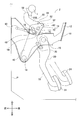
- the operation pedal mechanism 20 does not include the link member 30 and the intermediate lever 40 of the first embodiment. Therefore, the rotating shaft portion 14 and the caulking pin 80 fix the obtuse-angled V-shaped rotating member 50 to the operation pedal 22. As a result, the rotating shaft portion 14 and the caulking pin 80 are arranged on the axis 64 of the operating rod 60 between the upper end portion 22A and the lower end portion 22B of the operation pedal 22.
- the opening 26 is formed in the operation pedal 22 of the operation pedal mechanism 20 instead of the opening 42 of the first embodiment. Further, the protrusion 90 is arranged in the opening 26 of the operation pedal 22 in a state of being separated from the opening edge of the opening 26 by protruding to the right in the vehicle width direction at the front end 54 of the rotating member 50. It is installed.
- the rotating member 50 and the caulking pin 80 are added to the operation pedal mechanism 20. It is possible to prevent the tread portion 24 of the operation pedal mechanism 20 from retreating in the event of a vehicle collision, and even if the caulking pin 80 is broken due to some factor in normal times, the protrusion 90, the claw portion 92, By suppressing the rotation of the rotating member 50 around the rotating shaft portion 14 by the projecting piece portion 94 or the restraining pin 96, the stepping operation on the step portion 24 of the operation pedal mechanism 20 is enabled.
- a restraining load F2 acting on the protrusion 90, the claw 92, the projecting piece 94, or the restraining pin 96 as the rotation of the rotating member 50 around the rotating shaft 14 is restrained, and the tread 24 is in front of the vehicle. If the second reference load, which is larger than the second load when the vehicle is fully depressed to the side, is exceeded, the protrusion 90, the claw 92, or the projecting piece 94 is deformed, or the restraint pin 96 is broken, and the rotating shaft The restraint of rotation of the rotating member 50 centered on the portion 14 is released.
- the stepping operation on the step portion 24 of the operation pedal mechanism 20 is possible until the tread portion 24 is fully depressed toward the front side of the vehicle.
- the suppression of the rotation of the rotating member 50 centered on the rotating shaft portion 14 is released, and the tread portion 24 of the operation pedal mechanism 20 is prevented from retreating in the event of a vehicle collision. It is possible to do it again.
- the protrusion 90, the claw portion 92, or the projecting piece portion 94 is It is formed on the rotating member 50, and is centered on the rotating shaft portion 14 by being pressed against the opening edge of the opening 42 of the intermediate lever 40 in the operation pedal mechanism 20, the outer edge of the intermediate lever 40, or the connecting pin 70.
- a restraining load F2 accompanying the restraining of rotation of the rotating member 50 is applied to the protrusion 90, the claw 92, or the projecting piece 94.
- the tread portion 24 of the operation pedal mechanism 20 at the time of a vehicle collision is realized by a simple configuration.
- the restraint pin 96 is penetrated through the intermediate lever 40 of the rotating member 50 and the operation pedal mechanism 20 to rotate the rotating member 50 around the rotating shaft portion 14.
- the restraint load F2 accompanying the restraint of the above is applied to the restraint pin 96.
- the action point D of the restraint load F2 of the protrusion 90, the claw portion 92, the projecting piece portion 94, or the restraint pin 96 is the rotation shaft portion. Installation of the opening edge of the opening 42 of the intermediate lever 40 in the operation pedal mechanism 20, the outer edge of the intermediate lever 40, the connecting pin 70, and the intermediate lever 40 until the suppression of the rotation of the rotating member 50 centered on 14 is started. It is isolated from the opening edge forming the hole 44.
- the operating pedal mechanism at the time of a vehicle collision is provided by the protrusion 90 provided on the rotating member 50 and the opening 42 provided on the intermediate lever 40 of the operating pedal mechanism 20. It is easy to manufacture because it realizes a fail-safe function for preventing the treads 24 of 20 from retreating.
- the brake pedal device 2 of the second embodiment is manufactured because the claw portion 92 provided on the rotating member 50 realizes a fail-safe function for preventing the tread portion 24 of the operation pedal mechanism 20 from retreating in the event of a vehicle collision. Is easy.
- the connecting pin 70 is caught by the projecting piece portion 94 in the opening 42 of the intermediate lever 40, so that the rotating member 50 rotates around the rotating shaft portion 14. It is stopped and the tip 62 of the operating rod 60 is pushed toward the front side of the vehicle. Therefore, in the brake pedal device 3 of the third embodiment, in the intermediate lever 40 of the operation pedal mechanism 20, the connecting pin 70 penetrating the opening 42 and the projecting piece portion 94 extending from the opening edge of the opening 42 are used. Since the fail-safe function for preventing the tread portion 24 of the operation pedal mechanism 20 from retreating in the event of a vehicle collision is realized, the manufacturing is easy.
- the brake pedal devices 1, 2, 3, 4, and 5 are examples of "vehicle operation pedal devices”.
- the pedal bracket 10 is an example of a “support member”.
- the operating rod 60 is an example of a "vehicle control mechanism”.
- the tip 62 of the operating rod 60 is an example of an “input unit of a vehicle control mechanism”.
- the connecting pin 70 is an example of a “connecting portion”.
- the dash panel P is an example of the “first vehicle component”.
- the instrument panel reinforcement I and the collision bracket 200 are examples of the “second vehicle component”.
- the caulking pin 80 is an example of a "fixing member”.
- the protrusion 90 of the first embodiment and the fifth embodiment is an example of the "operation holding mechanism”.
- the claw portion 92 of the second embodiment is an example of the “operation holding mechanism”.
- the projecting piece portion 94 of the third embodiment is an example of the “operation holding mechanism”.
- the suppression pin 96 of the fourth embodiment is an example of the “operation holding mechanism”.
- the point of action D of the restraint load F2 is an example of "a place where the restraint load acts".
- the protrusion 90 is attached to the rotating member 50 so as to be separated from the outer edge of the upper end 40A of the intermediate lever 40 on the outer side of the upper end 40A of the intermediate lever 40. It may be provided so that the rotation of the rotating member 50 about the rotating shaft portion 14 is suppressed.
- the protrusion 90 is provided on the upper end 40A of the intermediate lever 40, and is arranged on the outer side of the bent portion 52 or the front end 54 of the rotating member 50 in a state of being separated from the outer edge of the rotating member 50. By doing so, the rotation of the rotating member 50 around the rotating shaft portion 14 may be suppressed.
- the claw portion 92 is in a state of being separated from the outer edge of the upper end portion 40A of the intermediate lever 40 on the vehicle front side or the vehicle upper side side of the upper end portion 40A of the intermediate lever 40.
- the rotating member 50 may be provided, whereby the rotation of the rotating member 50 around the rotating shaft portion 14 may be suppressed.
- the claw portion 92 is provided at the upper end portion 40A of the intermediate lever 40, and is arranged on the outer side of the bent portion 52 or the front end portion 54 of the rotating member 50 in a state of being separated from the outer edge of the rotating member 50. By doing so, the rotation of the rotating member 50 around the rotating shaft portion 14 may be suppressed.
- the caulking pin 80 when the caulking pin 80 is in a broken state due to some factor in the normal state, when the tread portion 24 is stepped on the front side of the vehicle by the driver, the upper end portion 56 of the rotating member 50 is pressed. Although it rotates to the front side of the vehicle about the rotation shaft portion 14, it may rotate to the rear side of the vehicle.
- the connecting pin 70 in the normal state penetrates into the lower portion of the vehicle in the opening 42 of the intermediate lever 40.
- the connecting pin 70 into which the rotating member 50 is fitted does not have to penetrate the opening 42 of the intermediate lever 40.
- the connecting pin 70 may be fitted through the front end portion 54 of the rotating member 50 arranged on the front side of the vehicle with respect to the upper end portion 40A of the intermediate lever 40.
- the caulking pin 80 is displaced upward, but downward.
- the present invention can be applied even if it is displaced to the side.
- the present invention is applied with the operation pedal 22 as a brake pedal, but the present invention may be applied as each pedal (for example, an accelerator pedal or a clutch pedal) used in a vehicle.
- the parts of the brake pedal devices 1, 2, 3, 4, and 5 of each embodiment are not limited to metal, and may be made of resin.
- 1,2,3,4,5 Brake pedal device (vehicle operation pedal device) 10 Pedal bracket (support member) 14 Rotating shaft 20 Operating pedal mechanism 24 Step 42 Opening 50 Rotating member 52 Bent 54 Front end 56 Upper end 60 Operating rod (Vehicle control mechanism) 62 Tip (input) 70 Connecting pin (connecting part) 80 caulking pin (fixing member) 90 Protrusion (operation holding mechanism) 92 Claw (operation holding mechanism) 94 Projection holding mechanism (operation holding mechanism) 96 Suppression pin (operation holding mechanism) 200 Collision bracket (second vehicle component) D Point of action of restraint load (location where restraint load acts) F1 Fixed load / Impact load F2 Suppression load P Dash panel (1st vehicle component) I Instrument panel reinforcement (second vehicle component)
Abstract
Provided is an operative pedal device which is for vehicles and is provided with a failsafe function for preventing the retreat of a tread part of an operative pedal during vehicle collision. A brake pedal device (1) is provided with a protrusion part (90) that performs rotation prevention for inhibiting a rotary member (50) from rotating about a rotary shaft part (14) and receives a suppressing load (F2) through the rotation prevention. In the protruding part (90), a second load acts as the suppression load (F2) when a tread part (24) of the operative pedal mechanism (20) is maximally pressed toward the vehicle front side during the rotation prevention, and when the suppression load (F2) exceeds the second load, the rotation prevention is released by shear or bending of the protrusion part (90).
Description
本発明は、車両衝突に伴って車両構成部材が車両後方側へ変位した場合に、操作ペダル機構の踏部が車両後方側へ後退することを抑える(以下、「車両衝突時における操作ペダル機構の踏部の後退防止」という。)車両用操作ペダル装置に関するものである。
The present invention suppresses the tread of the operation pedal mechanism from retreating to the rear side of the vehicle when the vehicle component is displaced to the rear side of the vehicle due to a vehicle collision (hereinafter, "the operation pedal mechanism at the time of a vehicle collision". It is called "prevention of backward movement of the tread".) It relates to an operation pedal device for a vehicle.
従来、車両衝突時における操作ペダルの踏部の後退防止が行われる車両用操作ペダル装置に関し、種々の技術が提案されている。
Conventionally, various technologies have been proposed for a vehicle operation pedal device that prevents the tread of the operation pedal from retreating in the event of a vehicle collision.
例えば、下記特許文献1に記載の技術は、車体に装着されたペダルハンガーにペダル軸を介してペダルアームの上端部を支持し、このペダルアームの途中に、エンジンルーム内に設置されたマスターシリンダのプッシュロッドを接続した車両のペダル支持構造において、上記ペダルアームの途中に第1のリンクの一端部を軸支し、この第1のリンクの他端部を、上記ペダル軸に他端部を係合した第2のリンクの一端部に軸支するとともに、上記第1のリンクの中間位置に上記プッシュロッドを連結し、車体前方からの過大な入力荷重に伴って上記ペダルハンガーが車体取付部側に対して相対的に移動したとき、上記第2のリンクの他端部係合部がペダル軸から離脱可能に構成したことを特徴とする。
For example, the technique described in Patent Document 1 below supports a pedal hanger mounted on a vehicle body with an upper end of a pedal arm via a pedal shaft, and a master cylinder installed in the engine room in the middle of the pedal arm. In the pedal support structure of the vehicle to which the push rod is connected, one end of the first link is pivotally supported in the middle of the pedal arm, and the other end of the first link is attached to the pedal shaft. Along with axially supporting one end of the engaged second link, the push rod is connected to an intermediate position of the first link, and the pedal hanger is attached to the vehicle body attachment portion due to an excessive input load from the front of the vehicle body. It is characterized in that the engaging portion at the other end of the second link is configured to be detachable from the pedal shaft when it moves relative to the side.
これにより、通常状態では、リンク機構と無関係にペダルアームが操作できるとともに、車体前方からの過大な衝撃荷重が加わった場合には、リンク機構を介してペダルアームを車体前方に回動させることができる。よって、機構が複雑にならずに動作を確実に行うことができる。
As a result, in the normal state, the pedal arm can be operated independently of the link mechanism, and when an excessive impact load from the front of the vehicle body is applied, the pedal arm can be rotated to the front of the vehicle body via the link mechanism. it can. Therefore, the operation can be reliably performed without complicating the mechanism.
しかしながら、通常状態において、異常の発生に伴って、リンク機構がペダルアーム又はペダル軸から外れてしまうと、ペダルアームを操作することが困難であった。
However, in the normal state, if the link mechanism is detached from the pedal arm or the pedal shaft due to the occurrence of an abnormality, it is difficult to operate the pedal arm.
そこで、本発明は、上述した点を鑑みてなされたものであり、車両衝突時における操作ペダル機構の踏部の後退防止に対するフェールセーフ機能を備えた車両用操作ペダル装置を提供することを課題とする。
Therefore, the present invention has been made in view of the above points, and an object of the present invention is to provide a vehicle operation pedal device having a fail-safe function for preventing the tread of the operation pedal mechanism from retreating in the event of a vehicle collision. To do.
この課題を解決するためになされた請求項1に係る発明は、車両用操作ペダル装置であって、第1車両構成部材に固定されたサポート部材と、サポート部材に設けられ、サポート部材に対して回動可能な踏部を有し、踏部が車両前方側へ踏み込まれる操作ペダル機構と、曲折部と、曲折部から車両前方側へ延出する前端部と、曲折部から上方側へ延出する上端部とを有し、曲折部において回転軸部で操作ペダル機構に対して回動可能に支持される回転部材と、回転部材の前端部において、第1車両構成部材から車両後方側へ突き出した車両用制御機構の入力部を回転部材に対して回動可能に保持する連結部と、回転部材の曲折部において、回転部材と操作ペダル機構を固定すると共に、操作ペダル機構の踏部が車両前方側へ最大に踏み込まれたときに第1荷重が作用する固定部材とを備え、踏部の踏み込みによる操作量を回転部材及び連結部を介して車両用制御機構に伝達すると共に、第1車両構成部材が車両衝突時に車両後方側へ変位した場合に、第1車両構成部材よりも車両後方側に配置されている第2車両構成部材に回転部材の上端部が当接することによって、固定部材に衝撃荷重が作用し、衝撃荷重が第1荷重よりも大きくなると、固定部材による回転部材と操作ペダル機構の固定が解除され、回転部材の上端部が回転軸部を中心にして車両前方側へ回転すると共に、回転部材の前端部及び車両用制御機構の入力部が連結部を介して上方側又は下方側へ変位することによって、操作ペダル機構の踏部が第1車両構成部材に対して車両前方側へ変位し、回転軸部を中心にして回転部材が回転することを妨げる回転抑止を行うと共に、回転抑止によって抑止荷重が作用する操作保持機構を備え、操作保持機構は、回転抑止の最中において、操作ペダル機構の踏部が車両前方側へ最大に踏み込まれたときに第2荷重が抑止荷重として作用し、抑止荷重が第2荷重よりも大きくなると、操作保持機構の変形に伴って、回転抑止を解除することを特徴とする。
The invention according to claim 1 made to solve this problem is a vehicle operation pedal device, which is provided on a support member fixed to a first vehicle component member and a support member provided on the support member. An operation pedal mechanism having a rotatable tread that allows the tread to be stepped on the front side of the vehicle, a bent part, a front end portion that extends from the bent part to the front side of the vehicle, and an upward extension from the bent part. A rotating member having an upper end portion that is rotatably supported by a rotating shaft portion at a bending portion with respect to an operation pedal mechanism, and a front end portion of the rotating member that protrudes from the first vehicle component member to the rear side of the vehicle. The rotating member and the operating pedal mechanism are fixed at the connecting portion that rotatably holds the input portion of the vehicle control mechanism with respect to the rotating member and the bent portion of the rotating member, and the step portion of the operating pedal mechanism is the vehicle. It is equipped with a fixing member on which the first load acts when the vehicle is fully depressed to the front side, and the amount of operation due to the depression of the step portion is transmitted to the vehicle control mechanism via the rotating member and the connecting portion, and the first vehicle. When the constituent member is displaced to the rear side of the vehicle at the time of a vehicle collision, the upper end portion of the rotating member comes into contact with the second vehicle constituent member arranged on the rear side of the vehicle with respect to the first vehicle constituent member, thereby forming the fixed member. When an impact load acts and the impact load becomes larger than the first load, the rotating member and the operation pedal mechanism are released from being fixed by the fixing member, and the upper end of the rotating member rotates toward the front of the vehicle around the rotating shaft. At the same time, the front end portion of the rotating member and the input portion of the vehicle control mechanism are displaced upward or downward via the connecting portion, so that the tread portion of the operation pedal mechanism is in front of the vehicle with respect to the first vehicle component member. A rotation restraint that displaces to the side and prevents the rotating member from rotating around the rotation shaft is provided, and an operation holding mechanism is provided in which a restraining load is applied by the rotation restraint. The operation holding mechanism is in the middle of rotation restraint. In the above, when the tread of the operation pedal mechanism is depressed to the front side of the vehicle to the maximum, the second load acts as a deterrent load, and when the deterrent load becomes larger than the second load, the operation holding mechanism is deformed. It is characterized by releasing the rotation restraint.
請求項2に係る発明は、請求項1に記載の車両用操作ペダル装置であって、操作保持機構は、操作ペダル機構又は回転部材に形成され、操作ペダル機構、回転部材、又は連結部との圧接によって、操作保持機構に抑止荷重を作用させることを特徴とする。
The invention according to claim 2 is the operation pedal device for a vehicle according to claim 1, wherein the operation holding mechanism is formed on the operation pedal mechanism or the rotating member, and is connected to the operation pedal mechanism, the rotating member, or the connecting portion. It is characterized in that a restraining load is applied to the operation holding mechanism by pressure welding.
請求項3に係る発明は、請求項1に記載の車両用操作ペダル装置であって、操作保持機構は、回転部材及び操作ペダル機構を貫通する抑止ピンであることを特徴とする。
The invention according to claim 3 is the vehicle operation pedal device according to claim 1, wherein the operation holding mechanism is a restraint pin penetrating the rotating member and the operation pedal mechanism.
請求項4に係る発明は、請求項2又は請求項3に記載の車両用操作ペダル装置であって、操作保持機構において、抑止荷重が作用する箇所は、回転抑止が開始されるまで、操作ペダル機構、回転部材、及び連結部から隔離していることを特徴とする。
The invention according to claim 4 is the vehicle operation pedal device according to claim 2 or 3, wherein in the operation holding mechanism, a portion where a restraining load acts is an operation pedal until rotation restraint is started. It is characterized by being isolated from the mechanism, the rotating member, and the connecting portion.
請求項5に係る発明は、請求項1に記載の車両用操作ペダル装置であって、操作保持機構は、回転部材に突設され、操作ペダル機構に形成された開口部に内在する突起部であり、突起部は、開口部の開口縁に突き当たることによって、回転抑止を行うと共に突起部に抑止荷重を作用させ、抑止荷重が第2荷重よりも大きくなると変形して、回転抑止を解除することを特徴とする。
The invention according to claim 5 is the operation pedal device for a vehicle according to claim 1, wherein the operation holding mechanism is a protrusion formed in an opening formed in the operation pedal mechanism so as to project from a rotating member. By hitting the opening edge of the opening, the protrusion suppresses rotation and applies a restraining load to the protrusion, and when the restraining load becomes larger than the second load, the protrusion is deformed to release the rotation restraint. It is characterized by.
請求項6に係る発明は、請求項1に記載の車両用操作ペダル装置であって、操作保持機構は、回転部材の縁端から突設された爪部であり、爪部は、操作ペダル機構の外縁に突き当たることによって、回転抑止を行うと共に爪部に抑止荷重を作用させ、抑止荷重が第2荷重よりも大きくなると変形して、回転抑止を解除することを特徴とする。
The invention according to claim 6 is the operation pedal device for a vehicle according to claim 1. The operation holding mechanism is a claw portion protruding from an edge of a rotating member, and the claw portion is an operation pedal mechanism. By hitting the outer edge of the wheel, rotation restraint is performed and a restraint load is applied to the claw portion, and when the restraint load becomes larger than the second load, the rotation is restrained and the rotation restraint is released.
請求項7に係る発明は、請求項1に記載の車両用操作ペダル装置であって、連結部は、操作ペダル機構に形成された開口部に貫入され、操作保持機構は、開口部の開口縁から開口部の内方側へ延出する突片部であり、突片部は、連結部が突き当たることによって、回転抑止を行うと共に突片部に抑止荷重を作用させ、抑止荷重が第2荷重よりも大きくなると変形して、回転抑止を解除することを特徴とする。
The invention according to claim 7 is the vehicle operation pedal device according to claim 1, wherein the connecting portion is penetrated into an opening formed in the operation pedal mechanism, and the operation holding mechanism is an opening edge of the opening. It is a projecting piece that extends inward from the opening, and when the connecting part abuts, the projecting piece suppresses rotation and applies a deterrent load to the projecting piece, and the deterrent load is the second load. It is characterized in that it deforms when it becomes larger than that and releases the rotation restraint.
本発明の車両用操作ペダル装置は、車両衝突時における操作ペダル機構の踏部の後退防止に対するフェールセーフ機能を備えたものである。
The vehicle operation pedal device of the present invention has a fail-safe function to prevent the tread of the operation pedal mechanism from retreating in the event of a vehicle collision.
以下、本発明に係る車両用操作ペダル装置について、常用ブレーキ用のブレーキペダル装置で具体化した実施形態に基づき、図面を参照しつつ説明する。以下の説明に用いる各図面では、基本的構成の一部が省略されて描かれており、描かれた各部の寸法比等は必ずしも正確ではない。
Hereinafter, the operation pedal device for a vehicle according to the present invention will be described with reference to the drawings based on the embodiment embodied in the brake pedal device for a regular brake. In each drawing used in the following description, a part of the basic configuration is omitted, and the dimensional ratio of each drawn part is not always accurate.
各図において、前後方向、上下方向、及び左右方向は、各図に記載された通りである。但し、図1、図3乃至図5、図8乃至図13、及び図15乃至図19では、図の紙面の奥側が右方向であり、図の紙面の手前側が左方向である。図2、図7、及び図14では、図の紙面の奥側が上方向であり、図の紙面の手前側が下方向である。
In each figure, the front-back direction, the up-down direction, and the left-right direction are as described in each figure. However, in FIGS. 1, 3 to 5, 8 to 13, and 15 to 19, the back side of the paper surface of the drawing is the right direction, and the front side of the paper surface of the drawing is the left direction. In FIGS. 2, 7, and 14, the back side of the paper surface of the drawing is upward, and the front side of the paper surface of the drawing is downward.
尚、以下の説明では、前方向を「車両前方側」と記載し、後方向を「車両後方側」と記載し、上方向を「車両上方側」と記載し、下方向を「車両下方側」と記載する。また、左右方向を「車幅方向」と記載する。
In the following description, the front direction is described as "vehicle front side", the rear direction is described as "vehicle rear side", the upward direction is described as "vehicle upper side", and the downward direction is described as "vehicle lower side". ". In addition, the left-right direction is described as "vehicle width direction".
(1-1)第1実施形態の概略
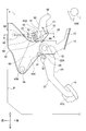
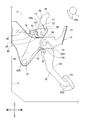
先ず、第1実施形態を説明する。図1及び図2に表されたように、第1実施形態のブレーキペダル装置1は、金属製であって、ペダルブラケット10、操作ペダル機構20、回転部材50、及びカシメピン80等を備えている。 (1-1) Outline of the First Embodiment First, the first embodiment will be described. As shown in FIGS. 1 and 2, thebrake pedal device 1 of the first embodiment is made of metal and includes a pedal bracket 10, an operation pedal mechanism 20, a rotating member 50, a caulking pin 80, and the like. ..
先ず、第1実施形態を説明する。図1及び図2に表されたように、第1実施形態のブレーキペダル装置1は、金属製であって、ペダルブラケット10、操作ペダル機構20、回転部材50、及びカシメピン80等を備えている。 (1-1) Outline of the First Embodiment First, the first embodiment will be described. As shown in FIGS. 1 and 2, the
ペダルブラケット10は、一対の側板12を有している。一対の側板12は、車幅方向で所定間隔を置いた状態で対向しており、ダッシュパネルPに対してボルト等で固定されている。ダッシュパネルPは、車両の一部を構成するものであって、操作ペダル機構20よりも車両前方側にある。一対の側板12の間には、操作ペダル機構20、回転部材50、及びカシメピン80等が配設されている。
The pedal bracket 10 has a pair of side plates 12. The pair of side plates 12 face each other at predetermined intervals in the vehicle width direction, and are fixed to the dash panel P with bolts or the like. The dash panel P constitutes a part of the vehicle and is located on the front side of the vehicle with respect to the operation pedal mechanism 20. An operation pedal mechanism 20, a rotating member 50, a caulking pin 80, and the like are arranged between the pair of side plates 12.
尚、図1では、一対の側板12のうち、車幅方向左側の側板12が表されており、車幅方向右側のものは表されていない。この点は、後述する図3乃至図5、図8乃至図13、及び図15乃至図19においても、同様である。
Note that, in FIG. 1, of the pair of side plates 12, the side plate 12 on the left side in the vehicle width direction is shown, and the side plate 12 on the right side in the vehicle width direction is not shown. This point is the same in FIGS. 3 to 5, 8 to 13, and 15 to 19 which will be described later.
操作ペダル機構20は、所謂リンク式の操作ペダル機構であって、操作ペダル22、リンク部材30、及び中間レバー40等を有している。操作ペダル22は、その上端部22Aに配設された操作軸部16によって、ペダルブラケット10に対して回動可能に支持されている。操作ペダル22の下端部22Bには、踏部24が設けられている。これにより、踏部24は、ペダルブラケット10に対して回動可能であり、車両の運転者によって車両前方側へ踏み込まれることが可能である。車両は、踏部24の踏み込みによる操作量(ペダルストローク及び踏力など)に応じて制御される。このようにして、踏部24の踏み込みによって車両制御が行われることを、操作ペダル機構20の踏部24に対する踏込み操作という。
The operation pedal mechanism 20 is a so-called link type operation pedal mechanism, and includes an operation pedal 22, a link member 30, an intermediate lever 40, and the like. The operation pedal 22 is rotatably supported with respect to the pedal bracket 10 by an operation shaft portion 16 arranged at the upper end portion 22A thereof. A tread 24 is provided on the lower end 22B of the operation pedal 22. As a result, the tread portion 24 is rotatable with respect to the pedal bracket 10 and can be stepped on the front side of the vehicle by the driver of the vehicle. The vehicle is controlled according to the amount of operation (pedal stroke, pedaling force, etc.) by stepping on the tread 24. The vehicle control performed by stepping on the tread 24 in this way is referred to as a stepping operation on the tread 24 of the operation pedal mechanism 20.
中間レバー40は、その下端部40Bに配設された中間軸部18によって、ペダルブラケット10に対して回動可能に支持されている。中間レバー40の上端部40Aには、回転軸部14及びカシメピン80が配設されている。更に、中間レバー40の上端部40Aには、回転軸部14及びカシメピン80よりも車両前方側において、開口部42が形成されている。開口部42は、車両後方側へ向かうに連れて、車両下方側へ向かうように傾斜している。中間レバー40の中間部40Cは、操作ペダル22の上端部22Aと下端部22Bの間において、操作ペダル22とリンク部材30で連結されている。
The intermediate lever 40 is rotatably supported by the intermediate shaft portion 18 arranged at the lower end portion 40B thereof with respect to the pedal bracket 10. A rotating shaft portion 14 and a caulking pin 80 are arranged at the upper end portion 40A of the intermediate lever 40. Further, the upper end portion 40A of the intermediate lever 40 is formed with an opening 42 on the front side of the vehicle with respect to the rotating shaft portion 14 and the caulking pin 80. The opening 42 is inclined so as to be directed toward the lower side of the vehicle toward the rear side of the vehicle. The intermediate portion 40C of the intermediate lever 40 is connected to the operating pedal 22 by a link member 30 between the upper end portion 22A and the lower end portion 22B of the operating pedal 22.
リンク部材30は、第1リンクピン32及び第2リンクピン34を有している。第1リンクピン32は、リンク部材30の車両後方部分に配設され、リンク部材30と操作ペダル22を連結している。これに対して、第2リンクピン34は、リンク部材30の車両前方部分に配設され、リンク部材30と中間レバー40を連結している。
The link member 30 has a first link pin 32 and a second link pin 34. The first link pin 32 is arranged at the rear portion of the vehicle of the link member 30, and connects the link member 30 and the operation pedal 22. On the other hand, the second link pin 34 is arranged in the front portion of the vehicle of the link member 30, and connects the link member 30 and the intermediate lever 40.
回転部材50は、金属製の板材であって、車幅方向左側から視てL字の形状をなしている。回転部材50は、曲折部52、前端部54、及び上端部56を有している。
The rotating member 50 is a metal plate material and has an L-shape when viewed from the left side in the vehicle width direction. The rotating member 50 has a bent portion 52, a front end portion 54, and an upper end portion 56.
回転部材50の曲折部52は、回転部材50の中央部分であって、回転部材50が折れ曲がった部分である。曲折部52には、上述した回転軸部14及びカシメピン80が配設されている。
The bent portion 52 of the rotating member 50 is a central portion of the rotating member 50, which is a bent portion of the rotating member 50. The above-mentioned rotating shaft portion 14 and caulking pin 80 are arranged in the bent portion 52.
回転軸部14及びカシメピン80は、カシメ加工がなされることによって、回転部材50の曲折部52及び中間レバー40の上端部40Aから、抜けないようにされている。これにより、回転軸部14及びカシメピン80は、回転部材50を中間レバー40に対して固定している。カシメピン80の強度は、回転軸部14の強度よりも小さくされる。例えば、図2に表されたように、カシメピン80の軸径が回転軸部14の軸径よりも小さくされることによって、カシメピン80の剪断強度が回転軸部14の剪断強度よりも小さくされる。あるいは、回転軸部14の材料よりも引張強度が低い材料で、カシメピン80が作られてもよい。そのため、カシメピン80が変形し、又は変形して破断すること(以下、「折損」という。)によって、カシメピン80による回転部材50と中間レバー40との固定が解除されると、回転部材50は、回転軸部14を中心にして、中間レバー40に対して回動することが可能となる。回転軸部14では、中間レバー40の板厚よりも若干大きな段が設けられることによって、中間レバー40が回動するときの摩擦抵抗が小さくされる。
The rotating shaft portion 14 and the caulking pin 80 are crimped so as not to come off from the bent portion 52 of the rotating member 50 and the upper end portion 40A of the intermediate lever 40. As a result, the rotating shaft portion 14 and the caulking pin 80 fix the rotating member 50 to the intermediate lever 40. The strength of the caulking pin 80 is made smaller than the strength of the rotating shaft portion 14. For example, as shown in FIG. 2, the shear strength of the caulking pin 80 is made smaller than the shear strength of the rotating shaft portion 14 by making the shaft diameter of the caulking pin 80 smaller than the shaft diameter of the rotating shaft portion 14. .. Alternatively, the caulking pin 80 may be made of a material having a tensile strength lower than that of the material of the rotating shaft portion 14. Therefore, when the caulking pin 80 is deformed or deformed and broken (hereinafter referred to as “breakage”), the rotating member 50 and the intermediate lever 40 are released from being fixed by the caulking pin 80. It is possible to rotate with respect to the intermediate lever 40 about the rotation shaft portion 14. The rotary shaft portion 14 is provided with a step slightly larger than the plate thickness of the intermediate lever 40, so that the frictional resistance when the intermediate lever 40 rotates is reduced.
尚、回転部材50が車幅方向右側にあり、中間レバー40が車幅方向左側にあるが、第1実施形態とは異なり、回転部材50が車幅方向左側にあり、中間レバー40が車幅方向右側にあってもよい。
The rotating member 50 is on the right side in the vehicle width direction and the intermediate lever 40 is on the left side in the vehicle width direction. However, unlike the first embodiment, the rotating member 50 is on the left side in the vehicle width direction and the intermediate lever 40 is on the vehicle width. It may be on the right side of the direction.
回転部材50の前端部54は、曲折部52から車両前方側へ延出した、回転部材50の部分である。前端部54には、オペレーティングロッド60の先端部62が、連結ピン70及びクレビス72を介して、回動可能に保持されている。更に、オペレーティングロッド60の軸線64を連結ピン70から車両後方側へ延長した線(以下、「オペレーティングロッド60の軸線64の延長線」という。)付近には、回転軸部14及びカシメピン80が配設されている。この点、回転軸部14は、オペレーティングロッド60の軸線64の延長線よりも僅かに車両下方側に配設されている。これに対して、カシメピン80は、オペレーティングロッド60の軸線64の延長線よりも車両上方側に配設されている。但し、回転軸部14及びカシメピン80は、オペレーティングロッド60の軸線64の延長線上に配設されてもよい。
The front end portion 54 of the rotating member 50 is a portion of the rotating member 50 extending from the bent portion 52 to the front side of the vehicle. At the front end portion 54, the tip end portion 62 of the operating rod 60 is rotatably held via the connecting pin 70 and the clevis 72. Further, a rotating shaft portion 14 and a caulking pin 80 are arranged in the vicinity of a line extending the axis 64 of the operating rod 60 from the connecting pin 70 to the rear side of the vehicle (hereinafter, referred to as “extension line of the axis 64 of the operating rod 60”). It is installed. In this respect, the rotating shaft portion 14 is arranged slightly below the vehicle extension line of the axis line 64 of the operating rod 60. On the other hand, the caulking pin 80 is arranged on the upper side of the vehicle with respect to the extension line of the axis 64 of the operating rod 60. However, the rotating shaft portion 14 and the caulking pin 80 may be arranged on an extension line of the axis 64 of the operating rod 60.
オペレーティングロッド60は、不図示のブレーキブースターを介してダッシュパネルPから車両後方側へ突き出ており、その突き出し方向を自由に変化させることが可能である。連結ピン70は、中間レバー40の上端部40Aに形成された開口部42のうち、車両上方部分に貫入された状態にあり、不図示のクリップによって、回転部材50の前端部54、中間レバー40の上端部40Aの開口部42、及びクレビス72から抜けないようにされている。
The operating rod 60 protrudes from the dash panel P to the rear side of the vehicle via a brake booster (not shown), and the protruding direction can be freely changed. The connecting pin 70 is in a state of being penetrated into the upper portion of the vehicle in the opening 42 formed in the upper end portion 40A of the intermediate lever 40, and the front end portion 54 of the rotating member 50 and the intermediate lever 40 are provided by a clip (not shown). It is prevented from coming off from the opening 42 of the upper end portion 40A and the clevis 72.
回転部材50の前端部54には、車幅方向左側から視て、中間レバー40の開口部42から露出する箇所において、突起部90が設けられている。突起部90は、車幅方向左側へ突出している。これにより、突起部90は、中間レバー40の開口部42内において、開口部42の開口縁から隔て離された状態で、連結ピン70よりも車両下方側に配設されている。尚、突起部90は、例えば、プレス加工によって設けられてもよいし、回転部材50とは別部材を回転部材50に圧入すること等によって設けられてもよい。
The front end portion 54 of the rotating member 50 is provided with a protrusion 90 at a portion exposed from the opening 42 of the intermediate lever 40 when viewed from the left side in the vehicle width direction. The protrusion 90 projects to the left in the vehicle width direction. As a result, the protrusion 90 is arranged in the opening 42 of the intermediate lever 40 on the lower side of the vehicle with respect to the connecting pin 70 in a state of being separated from the opening edge of the opening 42. The protrusion 90 may be provided, for example, by press working, or may be provided by press-fitting a member other than the rotating member 50 into the rotating member 50.
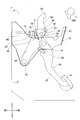
回転部材50の上端部56は、曲折部52から車両上方側へ延出した、回転部材50の部分である。上端部56よりも車両後方側には、長手方向が車幅方向へ配設された長尺状のインパネリインフォースメントIがある。従って、インパネリインフォースメントIは、ダッシュパネルPよりも車両後方側にある。インパネリインフォースメントIは、車両の一部を構成するものであって、衝突用ブラケット200等を有している。衝突用ブラケット200は、インパネリインフォースメントIの前端部から下端部に亘って固設されている。衝突用ブラケット200は、車両衝突時において、回転部材50の上端部56に突き当たるように配設されている。衝突用ブラケット200の車両前方側には、回転部材50が車両前方側へ容易に変位できるように、回転部材50の上端部56と当接するための当接面部が設けられている。回転部材50において、上端部56は、オペレーティングロッド60の軸線64よりもインパネリインフォースメントIがある方向へ伸び、衝突用ブラケット200の当接面部と当接する部分が湾曲形状をなしている。
The upper end 56 of the rotating member 50 is a portion of the rotating member 50 extending upward from the bent portion 52 of the vehicle. On the rear side of the vehicle with respect to the upper end portion 56, there is a long instrument panel reinforcement I arranged in the longitudinal direction in the vehicle width direction. Therefore, the instrument panel reinforcement I is located on the rear side of the vehicle with respect to the dash panel P. The instrument panel reinforcement I constitutes a part of the vehicle, and has a collision bracket 200 and the like. The collision bracket 200 is fixed from the front end portion to the lower end portion of the instrument panel reinforcement I. The collision bracket 200 is arranged so as to abut against the upper end portion 56 of the rotating member 50 at the time of a vehicle collision. On the front side of the vehicle of the collision bracket 200, a contact surface portion for contacting the upper end portion 56 of the rotating member 50 is provided so that the rotating member 50 can be easily displaced toward the front side of the vehicle. In the rotating member 50, the upper end portion 56 extends from the axis 64 of the operating rod 60 in a direction in which the instrument panel reinforcement I is located, and the portion that abuts the contact surface portion of the collision bracket 200 has a curved shape.
尚、回転軸部14、操作軸部16、中間軸部18、第1リンクピン32、第2リンクピン34、連結ピン70、及びカシメピン80は、一対の側板12の間において、略水平で且つ車幅方向と略平行な状態で配設されている。
The rotating shaft portion 14, the operating shaft portion 16, the intermediate shaft portion 18, the first link pin 32, the second link pin 34, the connecting pin 70, and the caulking pin 80 are substantially horizontal between the pair of side plates 12. It is arranged in a state substantially parallel to the vehicle width direction.
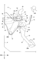
(1-2)通常時における第1実施形態の動作
通常時において、踏部24が車両前方側へ踏み込まれると、操作ペダル22は、操作軸部16を中心にして回転する。このとき、操作ペダル22は、操作軸部16を中心にして所定方向(図1における時計回り方向)へ回転するため、操作ペダル22の回転は、リンク部材30を介して、中間レバー40に対して伝達される。 (1-2) Operation of the First Embodiment in Normal Time In normal time, when thetread portion 24 is stepped on the front side of the vehicle, the operation pedal 22 rotates around the operation shaft portion 16. At this time, since the operation pedal 22 rotates in a predetermined direction (clockwise direction in FIG. 1) about the operation shaft portion 16, the rotation of the operation pedal 22 is performed with respect to the intermediate lever 40 via the link member 30. Is transmitted.
通常時において、踏部24が車両前方側へ踏み込まれると、操作ペダル22は、操作軸部16を中心にして回転する。このとき、操作ペダル22は、操作軸部16を中心にして所定方向(図1における時計回り方向)へ回転するため、操作ペダル22の回転は、リンク部材30を介して、中間レバー40に対して伝達される。 (1-2) Operation of the First Embodiment in Normal Time In normal time, when the
従って、中間レバー40は、操作ペダル22の回転に伴って、中間軸部18を中心にして所定方向(図1における反時計回り方向)へ回転する。そのため、回転部材50及びオペレーティングロッド60は、車両前方側へ変位する。
Therefore, the intermediate lever 40 rotates in a predetermined direction (counterclockwise direction in FIG. 1) around the intermediate shaft portion 18 as the operation pedal 22 rotates. Therefore, the rotating member 50 and the operating rod 60 are displaced toward the front side of the vehicle.
オペレーティングロッド60は、踏部24が車両前方側へ踏み込まれることに伴って車両前方側へ変位すると、その踏込み時の操作力を、油圧回路又は電子回路等を通して、車両の運転状態を制御する制動装置又は制御装置に伝達する。このようにして、操作ペダル機構20の踏部24に対する踏込み操作が行われる。
When the step portion 24 is displaced toward the front side of the vehicle as the step portion 24 is stepped on the front side of the vehicle, the operating rod 60 controls the operating force at the time of stepping on the driving state of the vehicle through a hydraulic circuit, an electronic circuit, or the like. Communicate to the device or control device. In this way, the stepping operation on the step portion 24 of the operation pedal mechanism 20 is performed.
その際、オペレーティングロッド60からの反力が、連結ピン70を介して回転部材50に作用すると共に、カシメピン80は、オペレーティングロッド60の軸線64の延長線上から外れていることから、カシメピン80には、荷重が作用する。このようにして、オペレーティングロッド60からの反力が、連結ピン70及び回転部材50を介して、カシメピン80に伝わることによって、カシメピン80に作用する荷重を、固定荷重という。符号F1は、固定荷重を示している。
At that time, the reaction force from the operating rod 60 acts on the rotating member 50 via the connecting pin 70, and the caulking pin 80 is deviated from the extension line of the axis 64 of the operating rod 60. , The load acts. The load that acts on the caulking pin 80 by transmitting the reaction force from the operating rod 60 to the caulking pin 80 via the connecting pin 70 and the rotating member 50 is called a fixed load. Reference numeral F1 indicates a fixed load.
尚、踏部24が運転者の操作荷重により車両前方側へ踏み込まれた場合において、更に、踏部24が車両前方側へ踏み込まれることによって、踏部24に作用する操作荷重が大きくなると、カシメピン80に作用する固定荷重も大きくなる。そこで、踏部24が車両前方側へ最大に踏み込まれ、操作荷重が設計上最大である場合にカシメピン80に作用する固定荷重を、第1荷重とする。
When the tread 24 is stepped on the front side of the vehicle by the operating load of the driver, when the tread 24 is further stepped on the front side of the vehicle and the operating load acting on the tread 24 is increased, the caulking pin is used. The fixed load acting on 80 also increases. Therefore, the fixed load acting on the caulking pin 80 when the tread portion 24 is stepped on to the front side of the vehicle to the maximum and the operating load is the maximum in design is defined as the first load.
(1-3)車両衝突時における第1実施形態の動作
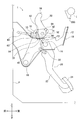
車両衝突時において、ダッシュパネルPが車両後方側へ変位すると、インパネリインフォースメントIの衝突用ブラケット200が、回転部材50に突き当たる。そのような場合にも、カシメピン80には、荷重が作用する。このようにして、カシメピン80に作用する荷重を、衝撃荷重という。そのような場合、符号F1は、上記した固定荷重でなく、衝撃荷重を示している。 (1-3) Operation of the First Embodiment in the Time of a Vehicle Collision When the dash panel P is displaced to the rear side of the vehicle in the case of a vehicle collision, thecollision bracket 200 of the instrument panel reinforcement I abuts on the rotating member 50. Even in such a case, a load acts on the caulking pin 80. The load acting on the caulking pin 80 in this way is called an impact load. In such a case, reference numeral F1 indicates an impact load instead of the fixed load described above.
車両衝突時において、ダッシュパネルPが車両後方側へ変位すると、インパネリインフォースメントIの衝突用ブラケット200が、回転部材50に突き当たる。そのような場合にも、カシメピン80には、荷重が作用する。このようにして、カシメピン80に作用する荷重を、衝撃荷重という。そのような場合、符号F1は、上記した固定荷重でなく、衝撃荷重を示している。 (1-3) Operation of the First Embodiment in the Time of a Vehicle Collision When the dash panel P is displaced to the rear side of the vehicle in the case of a vehicle collision, the
そして、衝撃荷重が、上述した第1荷重よりも大きな第1基準荷重を超えると、衝撃荷重によってカシメピン80が折損するため、カシメピン80が回転部材50及び中間レバー40から抜ける。これにより、カシメピン80による回転部材50と中間レバー40の固定が解除される。
Then, when the impact load exceeds the first reference load larger than the above-mentioned first load, the caulking pin 80 is broken by the impact load, so that the caulking pin 80 comes off from the rotating member 50 and the intermediate lever 40. As a result, the rotating member 50 and the intermediate lever 40 are released from being fixed by the caulking pin 80.
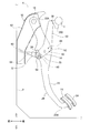
更に、図3に表されたように、回転部材50が衝突用ブラケット200で車両前方側へ押し出されることによって、回転部材50の上端部56が回転軸部14を中心にして車両前方側(図3における反時計回り方向)へ回転する。同時に、回転部材50の前端部54及びオペレーティングロッド60の先端部62が、連結ピン70及びクレビス72を介して、車両下方側へ変位する。その際、中間レバー40が車両前方側(図3における反時計回り方向)へ回転するので、操作ペダル22の踏部24が車両前方側へ変位する。
Further, as shown in FIG. 3, the rotating member 50 is pushed out to the front side of the vehicle by the collision bracket 200, so that the upper end portion 56 of the rotating member 50 is on the front side of the vehicle centering on the rotating shaft portion 14 (FIG. 3). Rotate in the counterclockwise direction in 3. At the same time, the front end portion 54 of the rotating member 50 and the tip end portion 62 of the operating rod 60 are displaced downward on the vehicle via the connecting pin 70 and the clevis 72. At that time, since the intermediate lever 40 rotates toward the front side of the vehicle (counterclockwise direction in FIG. 3), the tread portion 24 of the operation pedal 22 is displaced toward the front side of the vehicle.
このようにして、第1実施形態のブレーキペダル装置1では、所謂リンク式の操作ペダル機構20に対して、回転部材50及びカシメピン80が追加されることによって、車両衝突時における操作ペダル機構20の踏部24の後退防止を実現している。
In this way, in the brake pedal device 1 of the first embodiment, the rotating member 50 and the caulking pin 80 are added to the so-called link type operation pedal mechanism 20, so that the operation pedal mechanism 20 at the time of a vehicle collision The tread portion 24 is prevented from retreating.
尚、符号82,84は、カシメピン80を挿入するための取付穴を示している。取付穴82は、中間レバー40の上端部40Aに設けられたものであって、カシメピン80が嵌通可能な丸穴に形成されている。これに対して、取付穴84は、回転部材50の曲折部52に設けられたものであって、カシメピン80が貫通可能な長穴に形成されている。このような穴形状の相違により、取付穴82と取付穴84との間に生じる位置ずれを吸収している。もっとも、第1実施形態とは異なり、中間レバー40の上端部40Aに設けられた取付穴82が長穴であり、回転部材50の曲折部52に設けられた取付穴84が丸穴であってもよい。また、二点鎖線で表された踏部24は、操作ペダル機構20の踏部24に対する踏込み操作が解除されたときの踏部24の位置を示している。
Reference numerals 82 and 84 indicate mounting holes for inserting the caulking pin 80. The mounting hole 82 is provided in the upper end portion 40A of the intermediate lever 40, and is formed in a round hole into which the caulking pin 80 can be inserted. On the other hand, the mounting hole 84 is provided in the bent portion 52 of the rotating member 50, and is formed in an elongated hole through which the caulking pin 80 can penetrate. Due to such a difference in hole shape, the misalignment that occurs between the mounting hole 82 and the mounting hole 84 is absorbed. However, unlike the first embodiment, the mounting hole 82 provided in the upper end portion 40A of the intermediate lever 40 is a long hole, and the mounting hole 84 provided in the bent portion 52 of the rotating member 50 is a round hole. May be good. Further, the tread 24 represented by the alternate long and short dash line indicates the position of the tread 24 when the stepping operation on the tread 24 of the operation pedal mechanism 20 is released.
また、図3とは異なり、回転部材50の上端部56が回転軸部14を中心にして車両後方側(図3における時計回り方向)へ回転し、同時に、回転部材50の前端部54及びオペレーティングロッド60の先端部62が、連結ピン70及びクレビス72を介して、車両上方側へ変位しても、車両衝突時における操作ペダル機構20の踏部24の後退防止は可能である。
Further, unlike FIG. 3, the upper end portion 56 of the rotating member 50 rotates around the rotating shaft portion 14 toward the rear side of the vehicle (clockwise in FIG. 3), and at the same time, the front end portion 54 of the rotating member 50 and the operating member. Even if the tip 62 of the rod 60 is displaced upward on the vehicle via the connecting pin 70 and the clevis 72, it is possible to prevent the tread 24 of the operation pedal mechanism 20 from retreating in the event of a vehicle collision.
(1-4)通常時にカシメピン80が折損した場合の第1実施形態の動作
通常時であっても、何らかの要因によって、カシメピン80が折損した状態にある場合には、回転部材50が、回転軸部14を中心にして、中間レバー40に対して回動することが可能である。従って、このような状態において、踏部24が運転者に車両前方側へ踏み込まれ、中間レバー40が中間軸部18を中心にして所定方向(図1における反時計回り方向)へ回転し、オペレーティングロッド60からの反力が連結ピン70を介して回転部材50に作用すると、回転部材50の上端部56が、回転軸部14を中心にして車両前方側へ回転する(以下、このような回転を、「回転軸部14を中心にした回転部材50の回転」という)。同時に、回転部材50の前端部54及びオペレーティングロッド60の先端部62が、連結ピン70及びクレビス72を介して、車両下方側へ変位する。そのため、操作ペダル機構20の踏部24に対する踏込み操作は、空走の状態にある。 (1-4) Operation of the First Embodiment When theCaulking Pin 80 is Broken in the Normal Time Even in the normal time, if the caulking pin 80 is in a broken state due to some factor, the rotating member 50 moves the rotating shaft. It is possible to rotate with respect to the intermediate lever 40 about the portion 14. Therefore, in such a state, the tread 24 is stepped on by the driver toward the front of the vehicle, and the intermediate lever 40 rotates about the intermediate shaft 18 in a predetermined direction (counterclockwise in FIG. 1) to operate. When the reaction force from the rod 60 acts on the rotating member 50 via the connecting pin 70, the upper end portion 56 of the rotating member 50 rotates toward the front side of the vehicle around the rotating shaft portion 14 (hereinafter, such rotation). Is referred to as "rotation of the rotating member 50 around the rotating shaft portion 14"). At the same time, the front end portion 54 of the rotating member 50 and the tip end portion 62 of the operating rod 60 are displaced downward on the vehicle via the connecting pin 70 and the clevis 72. Therefore, the stepping operation on the step portion 24 of the operation pedal mechanism 20 is in a state of idling.
通常時であっても、何らかの要因によって、カシメピン80が折損した状態にある場合には、回転部材50が、回転軸部14を中心にして、中間レバー40に対して回動することが可能である。従って、このような状態において、踏部24が運転者に車両前方側へ踏み込まれ、中間レバー40が中間軸部18を中心にして所定方向(図1における反時計回り方向)へ回転し、オペレーティングロッド60からの反力が連結ピン70を介して回転部材50に作用すると、回転部材50の上端部56が、回転軸部14を中心にして車両前方側へ回転する(以下、このような回転を、「回転軸部14を中心にした回転部材50の回転」という)。同時に、回転部材50の前端部54及びオペレーティングロッド60の先端部62が、連結ピン70及びクレビス72を介して、車両下方側へ変位する。そのため、操作ペダル機構20の踏部24に対する踏込み操作は、空走の状態にある。 (1-4) Operation of the First Embodiment When the
しかしながら、更に、踏部24が運転者に車両前方側へ踏み込まれることによって、回転軸部14を中心にした回転部材50の回転が行われると、図4に表されたように、回転部材50の前端部54から突出した突起部90が、中間レバー40の開口部42の開口縁に突き当たるので、回転軸部14を中心にした回転部材50の回転が抑止される。
However, when the tread portion 24 is further stepped on by the driver toward the front side of the vehicle to rotate the rotating member 50 around the rotating shaft portion 14, the rotating member 50 is rotated as shown in FIG. Since the protrusion 90 protruding from the front end portion 54 of the above abuts the opening edge of the opening 42 of the intermediate lever 40, the rotation of the rotating member 50 around the rotating shaft portion 14 is suppressed.
このような状態において、更に、踏部24が運転者に車両前方側へ踏み込まれると、回転部材50は、中間軸部18を中心にして所定方向(図4における反時計回り方向)へ回転する中間レバー40と一体になって、車両前方側へ変位する。これにより、回転部材50の前端部54及びオペレーティングロッド60の先端部62は、連結ピン70及びクレビス72を介して、車両前方側へ変位する。そのため、操作ペダル機構20の踏部24に対する踏込み操作は、可能な状態になる。
In such a state, when the tread portion 24 is further stepped on by the driver toward the front side of the vehicle, the rotating member 50 rotates in a predetermined direction (counterclockwise direction in FIG. 4) about the intermediate shaft portion 18. It is integrated with the intermediate lever 40 and displaced toward the front side of the vehicle. As a result, the front end portion 54 of the rotating member 50 and the tip end portion 62 of the operating rod 60 are displaced toward the front side of the vehicle via the connecting pin 70 and the clevis 72. Therefore, the stepping operation on the step portion 24 of the operation pedal mechanism 20 becomes possible.
その際、突起部90は、中間レバー40の開口部42の開口縁に突き当たると、中間レバー40の開口部42の開口縁に圧接するので、突起部90には、荷重が作用する。このようにして、突起部90に作用する荷重を、抑止荷重F2という。
At that time, when the protrusion 90 hits the opening edge of the opening 42 of the intermediate lever 40, it presses against the opening edge of the opening 42 of the intermediate lever 40, so that a load acts on the protrusion 90. The load acting on the protrusion 90 in this way is referred to as a restraining load F2.
従って、突起部90において、抑止荷重F2の作用点D(つまり、突起部90が中間レバー40の開口部42の開口縁に圧接する箇所)は、回転軸部14を中心にした回転部材50の回転の抑止が開始されるまで、操作ペダル機構20における中間レバー40の開口部42の開口縁(、回転部材50、及び連結ピン70等)から隔離している。
Therefore, in the protrusion 90, the point of action D of the restraining load F2 (that is, the position where the protrusion 90 comes into pressure contact with the opening edge of the opening 42 of the intermediate lever 40) is the rotation member 50 centered on the rotation shaft portion 14. It is isolated from the opening edge (, the rotating member 50, the connecting pin 70, etc.) of the opening 42 of the intermediate lever 40 in the operation pedal mechanism 20 until the suppression of rotation is started.
また、突起部90の強度は、カシメピン80の強度よりも小さくされる。例えば、図2に表されたように、突起部90の軸径がカシメピン80の軸径よりも小さくされることによって、突起部90の剪断強度がカシメピン80の剪断強度よりも小さくされる。あるいは、カシメピン80の材料よりも引張強度が低い材料で、突起部90が作られてもよい。これにより、車両衝突時において、カシメピン80が折損すれば、突起部90が剪断又は曲げにより変形する。よって、突起部90は、車両衝突時における操作ペダル機構20の踏部24の後退防止を妨げるものではない。もっとも、突起部90の強度は、車両衝突時における操作ペダル機構20の踏部24の後退防止を妨げなければ、カシメピン80の強度よりも大きくなってもよい。
Further, the strength of the protrusion 90 is made smaller than the strength of the caulking pin 80. For example, as shown in FIG. 2, the shaft diameter of the protrusion 90 is made smaller than the shaft diameter of the caulking pin 80, so that the shear strength of the protrusion 90 is made smaller than the shear strength of the caulking pin 80. Alternatively, the protrusion 90 may be made of a material having a tensile strength lower than that of the caulking pin 80. As a result, if the caulking pin 80 is broken at the time of a vehicle collision, the protrusion 90 is deformed by shearing or bending. Therefore, the protrusion 90 does not prevent the step portion 24 of the operation pedal mechanism 20 from retreating in the event of a vehicle collision. However, the strength of the protrusion 90 may be higher than the strength of the caulking pin 80 as long as it does not prevent the step portion 24 of the operation pedal mechanism 20 from retreating in the event of a vehicle collision.
また、突起部90に抑止荷重F2が作用している状態、つまり、回転軸部14を中心にした回転部材50の回転が突起部90によって抑止されている状態において、踏部24が運転者の操作荷重により車両前方側へ踏み込まれる。更に、踏部24が車両前方側へ踏み込まれて、踏部24に作用する操作荷重が大きくなると、突起部90に作用する抑止荷重F2も大きくなる。そこで、踏部24が車両前方側へ最大に踏み込まれ、操作荷重が設計上最大である場合に突起部90に作用する抑止荷重F2を、第2荷重とする。
Further, in a state where the restraint load F2 is acting on the protrusion 90, that is, in a state where the rotation of the rotating member 50 about the rotation shaft portion 14 is restrained by the protrusion 90, the tread portion 24 is the driver's step. It is stepped on the front side of the vehicle by the operating load. Further, when the tread 24 is stepped on the front side of the vehicle and the operating load acting on the tread 24 becomes large, the restraining load F2 acting on the protrusion 90 also becomes large. Therefore, the restraining load F2 that acts on the protrusion 90 when the tread 24 is maximally stepped on the front side of the vehicle and the operating load is the maximum in design is defined as the second load.
そして、抑止荷重F2が、第2荷重よりも大きな第2基準荷重を超えると、抑止荷重F2によって突起部90が剪断又は曲げにより変形するので、回転軸部14を中心にした回転部材50の回転の抑止が解除される。従って、回転軸部14を中心にした回転部材50の回転が突起部90によって抑止されている状態(つまり、何らかの要因によって、カシメピン80が折損した状態にあるが、操作ペダル機構20の踏部24に対する踏込み操作が可能な状態)において、通常時から車両衝突時に移行しても、インパネリインフォースメントIの衝突用ブラケット200が回転部材50に突き当たることによって、抑止荷重F2が第2基準荷重を超えれば、車両衝突時における操作ペダル機構20の踏部24の後退防止が行われる。
When the restraining load F2 exceeds the second reference load larger than the second load, the protrusion 90 is deformed by shearing or bending due to the restraining load F2, so that the rotating member 50 rotates around the rotating shaft portion 14. Deterrence is released. Therefore, the rotation of the rotating member 50 about the rotating shaft portion 14 is suppressed by the protruding portion 90 (that is, the caulking pin 80 is in a broken state for some reason, but the tread portion 24 of the operation pedal mechanism 20 If the restraining load F2 exceeds the second reference load due to the collision bracket 200 of the instrument panel reinforcement I hitting the rotating member 50 even if the pedaling operation is changed from the normal time to the vehicle collision. , The tread portion 24 of the operation pedal mechanism 20 is prevented from retreating in the event of a vehicle collision.
また、通常時において、何らかの要因によって、カシメピン80が折損した場合であっても、操作ペダル機構20の踏部24に対する踏込み操作が一旦可能になれば、そのときの踏部24の位置から、運転者によって車両前方側へ最大に踏み込まれるまでの踏部24の位置までのペダルストロークにおいては、操作ペダル機構20の踏部24に対する踏込み操作が可能である。
Further, in the normal state, even if the caulking pin 80 is broken due to some factor, once the stepping operation on the step portion 24 of the operation pedal mechanism 20 becomes possible, the operation is performed from the position of the tread portion 24 at that time. In the pedal stroke up to the position of the step portion 24 until the person steps on the front side of the vehicle to the maximum, the stepping operation on the step portion 24 of the operation pedal mechanism 20 is possible.
尚、突起部90が中間レバー40の開口部42の開口縁に突き当たるまでは、操作ペダル機構20の踏部24に対する踏込み操作は空走の状態にある。よって、操作ペダル機構20の踏部24に対する踏込み操作が空走の状態にあるペダルストロークは、突起部90が回転部材50の上端部56から突出する位置を変更することによって調整することが可能である。
Until the protrusion 90 hits the opening edge of the opening 42 of the intermediate lever 40, the stepping operation on the step 24 of the operation pedal mechanism 20 is in an idle state. Therefore, the pedal stroke in which the stepping operation on the step portion 24 of the operation pedal mechanism 20 is in an idle state can be adjusted by changing the position where the protrusion 90 protrudes from the upper end portion 56 of the rotating member 50. is there.
(2)第2実施形態
次に、図5乃至図9に表された、第2実施形態のブレーキペダル装置2を説明する。図5、及び図7乃至図9は、上記第1実施形態の図1乃至図4に対応するものである。以下の説明では、上記第1実施形態と実質的に共通する部分には同一の符号を付し、詳しい説明を省略する。 (2) Second Embodiment Next, thebrake pedal device 2 of the second embodiment shown in FIGS. 5 to 9 will be described. 5 and 7 to 9 correspond to FIGS. 1 to 4 of the first embodiment. In the following description, the same reference numerals will be given to the parts substantially in common with the first embodiment, and detailed description thereof will be omitted.
次に、図5乃至図9に表された、第2実施形態のブレーキペダル装置2を説明する。図5、及び図7乃至図9は、上記第1実施形態の図1乃至図4に対応するものである。以下の説明では、上記第1実施形態と実質的に共通する部分には同一の符号を付し、詳しい説明を省略する。 (2) Second Embodiment Next, the
第2実施形態のブレーキペダル装置2は、上記第1実施形態の突起部90に代えて、その突起部90と機械的性質が同様な爪部92を備えている。爪部92は、回転部材50の曲折部52において、その車両下方側の縁端から車幅方向左側へ突出している。更に、爪部92は、中間レバー40の上端部40Aよりも車両後方側において、中間レバー40の上端部40Aの外縁から隔て離された状態で配設されている。
The brake pedal device 2 of the second embodiment includes a claw portion 92 having the same mechanical properties as the protrusion 90, instead of the protrusion 90 of the first embodiment. The claw portion 92 projects from the lower edge of the rotating member 50 to the left side in the vehicle width direction at the bent portion 52 of the rotating member 50. Further, the claw portion 92 is arranged on the rear side of the vehicle with respect to the upper end portion 40A of the intermediate lever 40 in a state of being separated from the outer edge of the upper end portion 40A of the intermediate lever 40.
第2実施形態のブレーキペダル装置2では、回転軸部14を中心にした回転部材50の回転が行われると、図9に表されたように、回転部材50の曲折部52の縁端から突出した爪部92が、中間レバー40の上端部40Aの外縁(つまり、操作ペダル機構20の外縁)に突き当たることにより、回転軸部14を中心にした回転部材50の回転が抑止される。更に、抑止荷重F2が、第2荷重よりも大きな第2基準荷重を超えると、抑止荷重F2によって爪部92が曲げにより変形して、回転軸部14を中心にした回転部材50の回転の抑止が解除される。このようにして、爪部92は、上記第1実施形態の突起部90と同様な機能を有するものである。
In the brake pedal device 2 of the second embodiment, when the rotating member 50 is rotated around the rotating shaft portion 14, as shown in FIG. 9, it protrudes from the edge of the bent portion 52 of the rotating member 50. When the claw portion 92 abuts on the outer edge of the upper end portion 40A of the intermediate lever 40 (that is, the outer edge of the operation pedal mechanism 20), the rotation of the rotating member 50 around the rotating shaft portion 14 is suppressed. Further, when the restraining load F2 exceeds the second reference load larger than the second load, the restraining load F2 deforms the claw portion 92 by bending, and restraining the rotation of the rotating member 50 around the rotating shaft portion 14. Is released. In this way, the claw portion 92 has the same function as the protrusion 90 of the first embodiment.
図6において、符号57は、回転部材50の曲折部52に設けられた取付穴であって、回転軸部14が嵌通可能な丸穴に形成された取付穴を示している。これに対して、符号58は、回転部材50の前端部54に設けられた取付穴であって、連結ピン70が嵌通可能な丸穴に形成された取付穴を示している。尚、これらの取付穴57,58は、他の実施形態においても、同様に設けられている。
In FIG. 6, reference numeral 57 is a mounting hole provided in the bent portion 52 of the rotating member 50, and indicates a mounting hole formed in a round hole into which the rotating shaft portion 14 can be fitted. On the other hand, reference numeral 58 indicates a mounting hole provided in the front end portion 54 of the rotating member 50, which is formed in a round hole into which the connecting pin 70 can be fitted. It should be noted that these mounting holes 57 and 58 are similarly provided in other embodiments.
(3)第3実施形態
次に、図10乃至図12に表された、第3実施形態のブレーキペダル装置3を説明する。図10乃至図12は、上記第1実施形態の図1、図3、及び図4に対応するものである。以下の説明では、上記第1実施形態と実質的に共通する部分には同一の符号を付し、詳しい説明を省略する。 (3) Third Embodiment Next, thebrake pedal device 3 of the third embodiment shown in FIGS. 10 to 12 will be described. 10 to 12 correspond to FIGS. 1, 3, and 4 of the first embodiment. In the following description, the same reference numerals will be given to the parts substantially in common with the first embodiment, and detailed description thereof will be omitted.
次に、図10乃至図12に表された、第3実施形態のブレーキペダル装置3を説明する。図10乃至図12は、上記第1実施形態の図1、図3、及び図4に対応するものである。以下の説明では、上記第1実施形態と実質的に共通する部分には同一の符号を付し、詳しい説明を省略する。 (3) Third Embodiment Next, the
第3実施形態のブレーキペダル装置3は、上記第1実施形態の突起部90に代えて、その突起部90と機械的性質が同様な突片部94を備えている。突片部94は、操作ペダル機構20の中間レバー40の開口部42において、その開口縁から内方側へ延出している。更に、突片部94は、中間レバー40の開口部42内の連結ピン70の車両下方側において、連結ピン70から隔て離された状態で配設されている。
The brake pedal device 3 of the third embodiment includes a protrusion 94 having the same mechanical properties as the protrusion 90, instead of the protrusion 90 of the first embodiment. The projecting piece portion 94 extends inward from the opening edge of the opening 42 of the intermediate lever 40 of the operation pedal mechanism 20. Further, the projecting piece portion 94 is arranged on the vehicle lower side of the connecting pin 70 in the opening 42 of the intermediate lever 40 in a state of being separated from the connecting pin 70.
第3実施形態のブレーキペダル装置3では、回転軸部14を中心にした回転部材50の回転が行われると、図12に表されたように、中間レバー40の開口部42の開口縁から延出した突片部94に対して、回転部材50に嵌通された連結ピン70が突き当たることにより、回転軸部14を中心にした回転部材50の回転が抑止される。更に、抑止荷重F2が、第2荷重よりも大きな第2基準荷重を超えると、抑止荷重F2によって突片部94が曲げにより変形して、回転軸部14を中心にした回転部材50の回転の抑止が解除される。このようにして、突片部94は、上記第1実施形態の突起部90と同様な機能を有するものである。
In the brake pedal device 3 of the third embodiment, when the rotating member 50 is rotated around the rotating shaft portion 14, it extends from the opening edge of the opening 42 of the intermediate lever 40 as shown in FIG. The connecting pin 70 fitted into the rotating member 50 abuts against the protruding piece portion 94, so that the rotation of the rotating member 50 around the rotating shaft portion 14 is suppressed. Further, when the restraining load F2 exceeds the second reference load larger than the second load, the thrusting piece portion 94 is deformed by bending due to the restraining load F2, and the rotating member 50 rotates around the rotating shaft portion 14. The deterrence is released. In this way, the projecting piece portion 94 has the same function as the protruding portion 90 of the first embodiment.
(4)第4実施形態
次に、図13乃至図16に表された、第4実施形態のブレーキペダル装置4を説明する。図13乃至図16は、上記第1実施形態の図1乃至図4に対応するものである。以下の説明では、上記第1実施形態と実質的に共通する部分には同一の符号を付し、詳しい説明を省略する。 (4) Fourth Embodiment Next, thebrake pedal device 4 of the fourth embodiment shown in FIGS. 13 to 16 will be described. 13 to 16 correspond to FIGS. 1 to 4 of the first embodiment. In the following description, the same reference numerals will be given to the parts substantially in common with the first embodiment, and detailed description thereof will be omitted.
次に、図13乃至図16に表された、第4実施形態のブレーキペダル装置4を説明する。図13乃至図16は、上記第1実施形態の図1乃至図4に対応するものである。以下の説明では、上記第1実施形態と実質的に共通する部分には同一の符号を付し、詳しい説明を省略する。 (4) Fourth Embodiment Next, the
第4実施形態のブレーキペダル装置4は、上記第1実施形態の突起部90に代えて、その突起部90と機械的性質が同様な抑止ピン96を備えている。抑止ピン96は、回転軸部14よりも車両上方側において、カシメ加工がなされることによって、回転部材50及び操作ペダル機構20の中間レバー40に貫通した状態で取り付けられている。
The brake pedal device 4 of the fourth embodiment includes a suppression pin 96 having the same mechanical properties as the protrusion 90, instead of the protrusion 90 of the first embodiment. The restraint pin 96 is attached to the rotating member 50 and the intermediate lever 40 of the operation pedal mechanism 20 in a state of being penetrated by caulking on the upper side of the vehicle with respect to the rotating shaft portion 14.
符号44,59は、抑止ピン96を挿入するための取付穴を示している。取付穴44は、中間レバー40の上端部40Aに設けられたものであって、抑止ピン96が貫通可能な長穴に形成されている。これに対して、取付穴59は、回転部材50の曲折部52に設けられたものであって、抑止ピン96が嵌通可能な丸穴に形成されている。これにより、取付穴44と取付穴59との間に生じる位置ずれを吸収している。また、図13に表されたように、通常時において、抑止ピン96は、中間レバー40の取付穴44のうち、車両後方部分に配設されているが、中間レバー40の取付穴44を形成する開口縁から隔て離された状態にある。
Reference numerals 44 and 59 indicate mounting holes for inserting the suppression pin 96. The mounting hole 44 is provided in the upper end portion 40A of the intermediate lever 40, and is formed in an elongated hole through which the restraint pin 96 can penetrate. On the other hand, the mounting hole 59 is provided in the bent portion 52 of the rotating member 50, and is formed in a round hole into which the restraining pin 96 can be inserted. As a result, the misalignment that occurs between the mounting hole 44 and the mounting hole 59 is absorbed. Further, as shown in FIG. 13, in the normal state, the restraint pin 96 is arranged in the rear portion of the vehicle among the mounting holes 44 of the intermediate lever 40, but forms the mounting holes 44 of the intermediate lever 40. It is in a state of being separated from the opening edge.
第4実施形態のブレーキペダル装置4では、回転軸部14を中心にした回転部材50の回転が行われると、図16に表されたように、中間レバー40の取付穴44のうち、車両前方部分を形成する開口縁に対して、回転部材50に嵌通された抑止ピン96が突き当たることにより、回転軸部14を中心にした回転部材50の回転が抑止される。更に、抑止荷重F2が、第2荷重よりも大きな第2基準荷重を超えると、抑止荷重F2によって抑止ピン96が変形し、又は変形して破断すること(以下、「折損」という。)によって、回転軸部14を中心にした回転部材50の回転の抑止が解除される。このようにして、抑止ピン96は、上記第1実施形態の突起部90と同様な機能を有するものである。
In the brake pedal device 4 of the fourth embodiment, when the rotating member 50 is rotated around the rotating shaft portion 14, as shown in FIG. 16, among the mounting holes 44 of the intermediate lever 40, the front of the vehicle The restraint pin 96 fitted into the rotary member 50 abuts against the opening edge forming the portion, so that the rotation of the rotary member 50 around the rotary shaft portion 14 is restrained. Further, when the restraint load F2 exceeds the second reference load larger than the second load, the restraint pin 96 is deformed or deformed and broken by the restraint load F2 (hereinafter, referred to as “breakage”). The restraint of rotation of the rotating member 50 around the rotating shaft portion 14 is released. In this way, the restraint pin 96 has the same function as the protrusion 90 of the first embodiment.
(5)第5実施形態
次に、図17乃至図19に表された、第5実施形態のブレーキペダル装置5を説明する。図17乃至図19は、上記第1実施形態の図1、図3、及び図4に対応するものである。以下の説明では、上記第1実施形態と実質的に共通する部分には同一の符号を付し、詳しい説明を省略する。 (5) Fifth Embodiment Next, thebrake pedal device 5 of the fifth embodiment shown in FIGS. 17 to 19 will be described. 17 to 19 correspond to FIGS. 1, 3, and 4 of the first embodiment. In the following description, the same reference numerals will be given to the parts substantially in common with the first embodiment, and detailed description thereof will be omitted.
次に、図17乃至図19に表された、第5実施形態のブレーキペダル装置5を説明する。図17乃至図19は、上記第1実施形態の図1、図3、及び図4に対応するものである。以下の説明では、上記第1実施形態と実質的に共通する部分には同一の符号を付し、詳しい説明を省略する。 (5) Fifth Embodiment Next, the
第5実施形態のブレーキペダル装置5において、操作ペダル機構20は、上記第1実施形態のリンク部材30及び中間レバー40を備えていない。そのため、回転軸部14及びカシメピン80は、鈍角のV字形状の回転部材50を操作ペダル22に対して固定している。これにより、操作ペダル22の上端部22Aと下端部22Bの間において、回転軸部14及びカシメピン80が、オペレーティングロッド60の軸線64上に配設されている。
In the brake pedal device 5 of the fifth embodiment, the operation pedal mechanism 20 does not include the link member 30 and the intermediate lever 40 of the first embodiment. Therefore, the rotating shaft portion 14 and the caulking pin 80 fix the obtuse-angled V-shaped rotating member 50 to the operation pedal 22. As a result, the rotating shaft portion 14 and the caulking pin 80 are arranged on the axis 64 of the operating rod 60 between the upper end portion 22A and the lower end portion 22B of the operation pedal 22.
第5実施形態のブレーキペダル装置5は、上記第1実施形態の開口部42に代えて、開口部26が、操作ペダル機構20の操作ペダル22に形成されている。また、突起部90は、回転部材50の前端部54において、車幅方向右側へ突出することによって、操作ペダル22の開口部26内において、開口部26の開口縁から隔て離された状態で配設されている。
In the brake pedal device 5 of the fifth embodiment, the opening 26 is formed in the operation pedal 22 of the operation pedal mechanism 20 instead of the opening 42 of the first embodiment. Further, the protrusion 90 is arranged in the opening 26 of the operation pedal 22 in a state of being separated from the opening edge of the opening 26 by protruding to the right in the vehicle width direction at the front end 54 of the rotating member 50. It is installed.
第5実施形態のブレーキペダル装置5では、回転軸部14を中心にした回転部材50の回転が行われると、図19に表されたように、回転部材50の前端部54から突出した突起部90が、操作ペダル22の開口部26の開口縁に突き当たることにより、回転軸部14を中心にした回転部材50の回転が抑止される。
In the brake pedal device 5 of the fifth embodiment, when the rotating member 50 is rotated around the rotating shaft portion 14, as shown in FIG. 19, a protruding portion protruding from the front end portion 54 of the rotating member 50. When the 90 abuts on the opening edge of the opening 26 of the operation pedal 22, the rotation of the rotating member 50 about the rotating shaft portion 14 is suppressed.
(6)まとめ
以上詳細に説明したように、各実施形態のブレーキペダル装置1,2,3,4,5では、操作ペダル機構20に対して、回転部材50及びカシメピン80が追加されることによって、車両衝突時における操作ペダル機構20の踏部24の後退防止を行うことが可能にされ、そのカシメピン80が、通常時において、何らかの要因によって、折損しても、突起部90、爪部92、突片部94、又は抑止ピン96が、回転軸部14を中心にした回転部材50の回転を抑止することによって、操作ペダル機構20の踏部24に対する踏込み操作が可能にされる。 (6) Summary As described in detail above, in the brake pedal devices 1, 2, 3, 4, and 5 of each embodiment, the rotating member 50 and the caulking pin 80 are added to the operation pedal mechanism 20. It is possible to prevent the tread portion 24 of the operation pedal mechanism 20 from retreating in the event of a vehicle collision, and even if the caulking pin 80 is broken due to some factor in normal times, the protrusion 90, the claw portion 92, By suppressing the rotation of the rotating member 50 around the rotating shaft portion 14 by the projecting piece portion 94 or the restraining pin 96, the stepping operation on the step portion 24 of the operation pedal mechanism 20 is enabled.
以上詳細に説明したように、各実施形態のブレーキペダル装置1,2,3,4,5では、操作ペダル機構20に対して、回転部材50及びカシメピン80が追加されることによって、車両衝突時における操作ペダル機構20の踏部24の後退防止を行うことが可能にされ、そのカシメピン80が、通常時において、何らかの要因によって、折損しても、突起部90、爪部92、突片部94、又は抑止ピン96が、回転軸部14を中心にした回転部材50の回転を抑止することによって、操作ペダル機構20の踏部24に対する踏込み操作が可能にされる。 (6) Summary As described in detail above, in the
回転軸部14を中心にした回転部材50の回転の抑止に伴って、突起部90、爪部92、突片部94、又は抑止ピン96に作用する抑止荷重F2が、踏部24が車両前方側へ最大に踏み込まれた際の第2荷重よりも大きな第2基準荷重を超えると、突起部90、爪部92、又は突片部94が変形し、若しくは抑止ピン96が折損し、回転軸部14を中心にした回転部材50の回転の抑止が解除される。従って、回転軸部14を中心にした回転部材50の回転が抑止されている状態では、踏部24が車両前方側へ最大に踏み込まれるまで、操作ペダル機構20の踏部24に対する踏込み操作が可能にされており、通常時から車両衝突時に移行すると、回転軸部14を中心にした回転部材50の回転の抑止が解除されて、車両衝突時における操作ペダル機構20の踏部24の後退防止を行うことが再び可能にされる。
A restraining load F2 acting on the protrusion 90, the claw 92, the projecting piece 94, or the restraining pin 96 as the rotation of the rotating member 50 around the rotating shaft 14 is restrained, and the tread 24 is in front of the vehicle. If the second reference load, which is larger than the second load when the vehicle is fully depressed to the side, is exceeded, the protrusion 90, the claw 92, or the projecting piece 94 is deformed, or the restraint pin 96 is broken, and the rotating shaft The restraint of rotation of the rotating member 50 centered on the portion 14 is released. Therefore, in a state where the rotation of the rotating member 50 centered on the rotating shaft portion 14 is suppressed, the stepping operation on the step portion 24 of the operation pedal mechanism 20 is possible until the tread portion 24 is fully depressed toward the front side of the vehicle. When the transition from the normal time to the vehicle collision occurs, the suppression of the rotation of the rotating member 50 centered on the rotating shaft portion 14 is released, and the tread portion 24 of the operation pedal mechanism 20 is prevented from retreating in the event of a vehicle collision. It is possible to do it again.
このようにして、各実施形態のブレーキペダル装置1,2,3,4,5では、車両衝突時における操作ペダル機構20の踏部24の後退防止に対するフェールセーフ機能が実現されている。
In this way, in the brake pedal devices 1, 2, 3, 4, and 5 of each embodiment, a fail-safe function for preventing the tread portion 24 of the operation pedal mechanism 20 from retreating in the event of a vehicle collision is realized.
また、第1実施形態、第2実施形態、第3実施形態、又は第5実施形態のブレーキペダル装置1,2,3,5では、突起部90、爪部92、又は突片部94が、回転部材50に形成されており、操作ペダル機構20における中間レバー40の開口部42の開口縁、中間レバー40の外縁、又は連結ピン70に対して圧接することによって、回転軸部14を中心にした回転部材50の回転の抑止に伴う抑止荷重F2を、突起部90、爪部92、又は突片部94に作用させている。このようにして、第1実施形態、第2実施形態、第3実施形態、又は第5実施形態のブレーキペダル装置1,2,3,5では、車両衝突時における操作ペダル機構20の踏部24の後退防止に対するフェールセーフ機能を簡単な構成によって実現されている。
Further, in the brake pedal devices 1, 2, 3 and 5 of the first embodiment, the second embodiment, the third embodiment, or the fifth embodiment, the protrusion 90, the claw portion 92, or the projecting piece portion 94 is It is formed on the rotating member 50, and is centered on the rotating shaft portion 14 by being pressed against the opening edge of the opening 42 of the intermediate lever 40 in the operation pedal mechanism 20, the outer edge of the intermediate lever 40, or the connecting pin 70. A restraining load F2 accompanying the restraining of rotation of the rotating member 50 is applied to the protrusion 90, the claw 92, or the projecting piece 94. In this way, in the brake pedal devices 1, 2, 3 and 5 of the first embodiment, the second embodiment, the third embodiment, or the fifth embodiment, the tread portion 24 of the operation pedal mechanism 20 at the time of a vehicle collision The fail-safe function for preventing the reverse of the pedal is realized by a simple configuration.
また、第4実施形態のブレーキペダル装置4では、抑止ピン96が、回転部材50及び操作ペダル機構20の中間レバー40に貫通されることによって、回転軸部14を中心にした回転部材50の回転の抑止に伴う抑止荷重F2を、抑止ピン96に作用させている。このようにして、第4実施形態のブレーキペダル装置4では、車両衝突時における操作ペダル機構20の踏部24の後退防止に対するフェールセーフ機能を簡単な構成によって実現されている。
Further, in the brake pedal device 4 of the fourth embodiment, the restraint pin 96 is penetrated through the intermediate lever 40 of the rotating member 50 and the operation pedal mechanism 20 to rotate the rotating member 50 around the rotating shaft portion 14. The restraint load F2 accompanying the restraint of the above is applied to the restraint pin 96. In this way, in the brake pedal device 4 of the fourth embodiment, a fail-safe function for preventing the tread portion 24 of the operation pedal mechanism 20 from retreating in the event of a vehicle collision is realized by a simple configuration.
また、各実施形態のブレーキペダル装置1,2,3,4,5において、突起部90、爪部92、突片部94、又は抑止ピン96の抑止荷重F2の作用点Dは、回転軸部14を中心にした回転部材50の回転の抑止が開始されるまで、操作ペダル機構20における中間レバー40の開口部42の開口縁、中間レバー40の外縁、連結ピン70、及び中間レバー40の取付穴44を形成する開口縁から隔離している。これにより、通常時の各実施形態のブレーキペダル装置1,2,3,4,5では、何らかの要因によって、カシメピン80が折損し、且つ、踏部24が車両前方側へ踏み込まれない限り、突起部90、爪部92、突片部94、又は抑止ピン96において、抑止荷重F2が作用することはない。
Further, in the brake pedal devices 1, 2, 3, 4, and 5 of each embodiment, the action point D of the restraint load F2 of the protrusion 90, the claw portion 92, the projecting piece portion 94, or the restraint pin 96 is the rotation shaft portion. Installation of the opening edge of the opening 42 of the intermediate lever 40 in the operation pedal mechanism 20, the outer edge of the intermediate lever 40, the connecting pin 70, and the intermediate lever 40 until the suppression of the rotation of the rotating member 50 centered on 14 is started. It is isolated from the opening edge forming the hole 44. As a result, in the brake pedal devices 1, 2, 3, 4, and 5 in the normal state, unless the caulking pin 80 is broken and the tread portion 24 is stepped on the front side of the vehicle for some reason, the protrusions The restraint load F2 does not act on the portion 90, the claw portion 92, the projecting piece portion 94, or the restraint pin 96.
また、第1実施形態のブレーキペダル装置1は、回転部材50に設けられた突起部90と、操作ペダル機構20の中間レバー40に設けられた開口部42とによって、車両衝突時における操作ペダル機構20の踏部24の後退防止に対するフェールセーフ機能を実現することから、製造が容易である。
Further, in the brake pedal device 1 of the first embodiment, the operating pedal mechanism at the time of a vehicle collision is provided by the protrusion 90 provided on the rotating member 50 and the opening 42 provided on the intermediate lever 40 of the operating pedal mechanism 20. It is easy to manufacture because it realizes a fail-safe function for preventing the treads 24 of 20 from retreating.
また、第2実施形態のブレーキペダル装置2は、回転部材50に設けられた爪部92によって、車両衝突時における操作ペダル機構20の踏部24の後退防止に対するフェールセーフ機能を実現ことから、製造が容易である。
Further, the brake pedal device 2 of the second embodiment is manufactured because the claw portion 92 provided on the rotating member 50 realizes a fail-safe function for preventing the tread portion 24 of the operation pedal mechanism 20 from retreating in the event of a vehicle collision. Is easy.
また、第3実施形態のブレーキペダル装置3では、中間レバー40の開口部42内において、連結ピン70が突片部94に引っ掛かることによって、回転軸部14を中心にした回転部材50の回転が止められ、オペレーティングロッド60の先端部62が車両前方側へ押し込まれる。従って、第3実施形態のブレーキペダル装置3は、操作ペダル機構20の中間レバー40において、開口部42を貫通した連結ピン70と、開口部42の開口縁から延出する突片部94とによって、車両衝突時における操作ペダル機構20の踏部24の後退防止に対するフェールセーフ機能を実現することから、製造が容易である。
Further, in the brake pedal device 3 of the third embodiment, the connecting pin 70 is caught by the projecting piece portion 94 in the opening 42 of the intermediate lever 40, so that the rotating member 50 rotates around the rotating shaft portion 14. It is stopped and the tip 62 of the operating rod 60 is pushed toward the front side of the vehicle. Therefore, in the brake pedal device 3 of the third embodiment, in the intermediate lever 40 of the operation pedal mechanism 20, the connecting pin 70 penetrating the opening 42 and the projecting piece portion 94 extending from the opening edge of the opening 42 are used. Since the fail-safe function for preventing the tread portion 24 of the operation pedal mechanism 20 from retreating in the event of a vehicle collision is realized, the manufacturing is easy.
(7)その他
ちなみに、各実施形態において、ブレーキペダル装置1,2,3,4,5は「車両用操作ペダル装置」の一例である。ペダルブラケット10は、「サポート部材」の一例である。オペレーティングロッド60は「車両用制御機構」の一例である。オペレーティングロッド60の先端部62は、「車両用制御機構の入力部」の一例である。連結ピン70は、「連結部」の一例である。ダッシュパネルPは、「第1車両構成部材」の一例である。インパネリインフォースメントI及び衝突用ブラケット200は、「第2車両構成部材」の一例である。 (7) Others By the way, in each embodiment, the brake pedal devices 1, 2, 3, 4, and 5 are examples of "vehicle operation pedal devices". The pedal bracket 10 is an example of a “support member”. The operating rod 60 is an example of a "vehicle control mechanism". The tip 62 of the operating rod 60 is an example of an “input unit of a vehicle control mechanism”. The connecting pin 70 is an example of a “connecting portion”. The dash panel P is an example of the “first vehicle component”. The instrument panel reinforcement I and the collision bracket 200 are examples of the “second vehicle component”.
ちなみに、各実施形態において、ブレーキペダル装置1,2,3,4,5は「車両用操作ペダル装置」の一例である。ペダルブラケット10は、「サポート部材」の一例である。オペレーティングロッド60は「車両用制御機構」の一例である。オペレーティングロッド60の先端部62は、「車両用制御機構の入力部」の一例である。連結ピン70は、「連結部」の一例である。ダッシュパネルPは、「第1車両構成部材」の一例である。インパネリインフォースメントI及び衝突用ブラケット200は、「第2車両構成部材」の一例である。 (7) Others By the way, in each embodiment, the
カシメピン80は、「固定部材」の一例である。第1実施形態及び第5実施形態の突起部90は、「操作保持機構」の一例である。第2実施形態の爪部92は、「操作保持機構」の一例である。第3実施形態の突片部94は、「操作保持機構」の一例である。第4実施形態の抑止ピン96は、「操作保持機構」の一例である。各実施形態において、抑止荷重F2の作用点Dは、「抑止荷重が作用する箇所」の一例である。
The caulking pin 80 is an example of a "fixing member". The protrusion 90 of the first embodiment and the fifth embodiment is an example of the "operation holding mechanism". The claw portion 92 of the second embodiment is an example of the “operation holding mechanism”. The projecting piece portion 94 of the third embodiment is an example of the “operation holding mechanism”. The suppression pin 96 of the fourth embodiment is an example of the “operation holding mechanism”. In each embodiment, the point of action D of the restraint load F2 is an example of "a place where the restraint load acts".
(8)変更例
尚、本発明は上記各実施形態に限定されるものでなく、その趣旨を逸脱しない範囲で様々な変更が可能である。
例えば、第1実施形態において、突起部90は、中間レバー40の上端部40Aの外方側において、中間レバー40の上端部40Aの外縁から隔て離された状態になるように、回転部材50に設けられ、これによって、回転軸部14を中心にした回転部材50の回転が抑止されるようにしてもよい。あるいは、突起部90は、中間レバー40の上端部40Aに設けられると共に、回転部材50の曲折部52又は前端部54の外方側において、回転部材50の外縁から隔て離された状態で配設されることによって、回転軸部14を中心にした回転部材50の回転が抑止されるようにしてもよい。 (8) Examples of Modifications The present invention is not limited to the above embodiments, and various modifications can be made without departing from the spirit of the present invention.
For example, in the first embodiment, theprotrusion 90 is attached to the rotating member 50 so as to be separated from the outer edge of the upper end 40A of the intermediate lever 40 on the outer side of the upper end 40A of the intermediate lever 40. It may be provided so that the rotation of the rotating member 50 about the rotating shaft portion 14 is suppressed. Alternatively, the protrusion 90 is provided on the upper end 40A of the intermediate lever 40, and is arranged on the outer side of the bent portion 52 or the front end 54 of the rotating member 50 in a state of being separated from the outer edge of the rotating member 50. By doing so, the rotation of the rotating member 50 around the rotating shaft portion 14 may be suppressed.
尚、本発明は上記各実施形態に限定されるものでなく、その趣旨を逸脱しない範囲で様々な変更が可能である。
例えば、第1実施形態において、突起部90は、中間レバー40の上端部40Aの外方側において、中間レバー40の上端部40Aの外縁から隔て離された状態になるように、回転部材50に設けられ、これによって、回転軸部14を中心にした回転部材50の回転が抑止されるようにしてもよい。あるいは、突起部90は、中間レバー40の上端部40Aに設けられると共に、回転部材50の曲折部52又は前端部54の外方側において、回転部材50の外縁から隔て離された状態で配設されることによって、回転軸部14を中心にした回転部材50の回転が抑止されるようにしてもよい。 (8) Examples of Modifications The present invention is not limited to the above embodiments, and various modifications can be made without departing from the spirit of the present invention.
For example, in the first embodiment, the
また、第2実施形態において、爪部92は、中間レバー40の上端部40Aよりも車両前方側又は車両上方側において、中間レバー40の上端部40Aの外縁から隔て離された状態になるように、回転部材50に設けられ、これによって、回転軸部14を中心にした回転部材50の回転が抑止されるようにしてもよい。あるいは、爪部92は、中間レバー40の上端部40Aに設けられると共に、回転部材50の曲折部52又は前端部54の外方側において、回転部材50の外縁から隔て離された状態で配設されることによって、回転軸部14を中心にした回転部材50の回転が抑止されるようにしてもよい。
Further, in the second embodiment, the claw portion 92 is in a state of being separated from the outer edge of the upper end portion 40A of the intermediate lever 40 on the vehicle front side or the vehicle upper side side of the upper end portion 40A of the intermediate lever 40. , The rotating member 50 may be provided, whereby the rotation of the rotating member 50 around the rotating shaft portion 14 may be suppressed. Alternatively, the claw portion 92 is provided at the upper end portion 40A of the intermediate lever 40, and is arranged on the outer side of the bent portion 52 or the front end portion 54 of the rotating member 50 in a state of being separated from the outer edge of the rotating member 50. By doing so, the rotation of the rotating member 50 around the rotating shaft portion 14 may be suppressed.
また、各実施形態では、通常時において、何らかの要因によって、カシメピン80が折損した状態にある場合に、踏部24が運転者に車両前方側へ踏み込まれると、回転部材50の上端部56が、回転軸部14を中心にして車両前方側へ回転するが、車両後方側へ回転してもよい。但し、第4実施形態では、通常時の連結ピン70が、中間レバー40の開口部42のうち、車両下方部分に貫入した状態にされる必要がある。
Further, in each embodiment, when the caulking pin 80 is in a broken state due to some factor in the normal state, when the tread portion 24 is stepped on the front side of the vehicle by the driver, the upper end portion 56 of the rotating member 50 is pressed. Although it rotates to the front side of the vehicle about the rotation shaft portion 14, it may rotate to the rear side of the vehicle. However, in the fourth embodiment, it is necessary that the connecting pin 70 in the normal state penetrates into the lower portion of the vehicle in the opening 42 of the intermediate lever 40.
また、第1実施形態、第2実施形態、第4実施形態、及び第5実施形態において、回転部材50を嵌通した連結ピン70は、中間レバー40の開口部42を貫通しなくてもよい。例えば、中間レバー40の上端部40Aよりも車両前方側に配設させた回転部材50の前端部54に対して、連結ピン70が嵌通してもよい。
Further, in the first embodiment, the second embodiment, the fourth embodiment, and the fifth embodiment, the connecting pin 70 into which the rotating member 50 is fitted does not have to penetrate the opening 42 of the intermediate lever 40. .. For example, the connecting pin 70 may be fitted through the front end portion 54 of the rotating member 50 arranged on the front side of the vehicle with respect to the upper end portion 40A of the intermediate lever 40.
また、各実施形態のブレーキペダル装置1,2,3,4,5は、操作ペダル機構20の踏部24に対する踏込み操作が行われると、カシメピン80が上方側へ変位するものであるが、下方側へ変位するものであっても、本発明を適用することが可能である。
Further, in the brake pedal devices 1, 2, 3, 4, 5 of each embodiment, when the stepping operation on the step portion 24 of the operation pedal mechanism 20 is performed, the caulking pin 80 is displaced upward, but downward. The present invention can be applied even if it is displaced to the side.
また、各実施形態では、操作ペダル22をブレーキペダルとして本発明が適用されているが、車両で使用される各ペダル(例えば、アクセルペダル又はクラッチペダル等)として本発明が適用されてもよい。
Further, in each embodiment, the present invention is applied with the operation pedal 22 as a brake pedal, but the present invention may be applied as each pedal (for example, an accelerator pedal or a clutch pedal) used in a vehicle.
各実施形態のブレーキペダル装置1,2,3,4,5の各部品は、金属製に限定されず、樹脂製であってもよい。
The parts of the brake pedal devices 1, 2, 3, 4, and 5 of each embodiment are not limited to metal, and may be made of resin.
1,2,3,4,5 ブレーキペダル装置(車両用操作ペダル装置)
10 ペダルブラケット(サポート部材)
14 回転軸部
20 操作ペダル機構
24 踏部
42 開口部
50 回転部材
52 曲折部
54 前端部
56 上端部
60 オペレーティングロッド(車両用制御機構)
62 先端部(入力部)
70 連結ピン(連結部)
80 カシメピン(固定部材)
90 突起部(操作保持機構)
92 爪部(操作保持機構)
94 突片部(操作保持機構)
96 抑止ピン(操作保持機構)
200 衝突用ブラケット(第2車両構成部材)
D 抑止荷重の作用点(抑止荷重が作用する箇所)
F1 固定荷重/衝撃荷重
F2 抑止荷重
P ダッシュパネル(第1車両構成部材)
I インパネリインフォースメント(第2車両構成部材) 1,2,3,4,5 Brake pedal device (vehicle operation pedal device)
10 Pedal bracket (support member)
14 Rotatingshaft 20 Operating pedal mechanism 24 Step 42 Opening 50 Rotating member 52 Bent 54 Front end 56 Upper end 60 Operating rod (Vehicle control mechanism)
62 Tip (input)
70 Connecting pin (connecting part)
80 caulking pin (fixing member)
90 Protrusion (operation holding mechanism)
92 Claw (operation holding mechanism)
94 Projection holding mechanism (operation holding mechanism)
96 Suppression pin (operation holding mechanism)
200 Collision bracket (second vehicle component)
D Point of action of restraint load (location where restraint load acts)
F1 Fixed load / Impact load F2 Suppression load P Dash panel (1st vehicle component)
I Instrument panel reinforcement (second vehicle component)
10 ペダルブラケット(サポート部材)
14 回転軸部
20 操作ペダル機構
24 踏部
42 開口部
50 回転部材
52 曲折部
54 前端部
56 上端部
60 オペレーティングロッド(車両用制御機構)
62 先端部(入力部)
70 連結ピン(連結部)
80 カシメピン(固定部材)
90 突起部(操作保持機構)
92 爪部(操作保持機構)
94 突片部(操作保持機構)
96 抑止ピン(操作保持機構)
200 衝突用ブラケット(第2車両構成部材)
D 抑止荷重の作用点(抑止荷重が作用する箇所)
F1 固定荷重/衝撃荷重
F2 抑止荷重
P ダッシュパネル(第1車両構成部材)
I インパネリインフォースメント(第2車両構成部材) 1,2,3,4,5 Brake pedal device (vehicle operation pedal device)
10 Pedal bracket (support member)
14 Rotating
62 Tip (input)
70 Connecting pin (connecting part)
80 caulking pin (fixing member)
90 Protrusion (operation holding mechanism)
92 Claw (operation holding mechanism)
94 Projection holding mechanism (operation holding mechanism)
96 Suppression pin (operation holding mechanism)
200 Collision bracket (second vehicle component)
D Point of action of restraint load (location where restraint load acts)
F1 Fixed load / Impact load F2 Suppression load P Dash panel (1st vehicle component)
I Instrument panel reinforcement (second vehicle component)
Claims (7)
- 第1車両構成部材に固定されたサポート部材と、
前記サポート部材に設けられ、前記サポート部材に対して回動可能な踏部を有し、前記踏部が車両前方側へ踏み込まれる操作ペダル機構と、
曲折部と、前記曲折部から車両前方側へ延出する前端部と、前記曲折部から上方側へ延出する上端部とを有し、前記曲折部において回転軸部で前記操作ペダル機構に対して回動可能に支持される回転部材と、
前記回転部材の前記前端部において、前記第1車両構成部材から車両後方側へ突き出した車両用制御機構の入力部を前記回転部材に対して回動可能に保持する連結部と、
前記回転部材の前記曲折部において、前記回転部材と前記操作ペダル機構を固定すると共に、前記操作ペダル機構の前記踏部が車両前方側へ最大に踏み込まれたときに第1荷重が作用する固定部材とを備え、
前記踏部の踏み込みによる操作量を前記回転部材及び前記連結部を介して前記車両用制御機構に伝達すると共に、
前記第1車両構成部材が車両衝突時に車両後方側へ変位した場合に、前記第1車両構成部材よりも車両後方側に配置されている第2車両構成部材に前記回転部材の前記上端部が当接することによって、前記固定部材に衝撃荷重が作用し、
前記衝撃荷重が前記第1荷重よりも大きくなると、前記固定部材による前記回転部材と前記操作ペダル機構の固定が解除され、前記回転部材の前記上端部が前記回転軸部を中心にして車両前方側へ回転すると共に、前記回転部材の前記前端部及び前記車両用制御機構の前記入力部が前記連結部を介して上方側又は下方側へ変位することによって、前記操作ペダル機構の前記踏部が前記第1車両構成部材に対して車両前方側へ変位し、
前記回転軸部を中心にして前記回転部材が回転することを妨げる回転抑止を行うと共に、前記回転抑止によって抑止荷重が作用する操作保持機構を備え、
前記操作保持機構は、前記回転抑止の最中において、前記操作ペダル機構の前記踏部が車両前方側へ最大に踏み込まれたときに第2荷重が前記抑止荷重として作用し、前記抑止荷重が前記第2荷重よりも大きくなると、前記操作保持機構の変形に伴って、前記回転抑止を解除することを特徴とする車両用操作ペダル装置。 Support members fixed to the first vehicle component and
An operation pedal mechanism provided on the support member, which has a tread that can rotate with respect to the support member, and the tread is stepped on the front side of the vehicle.
It has a bent portion, a front end portion extending from the bent portion to the front side of the vehicle, and an upper end portion extending upward from the bent portion. At the bent portion, a rotating shaft portion serves with respect to the operation pedal mechanism. Rotating members that are rotatably supported and
At the front end portion of the rotating member, a connecting portion that rotatably holds an input portion of a vehicle control mechanism protruding from the first vehicle component member toward the rear side of the vehicle with respect to the rotating member.
A fixing member that fixes the rotating member and the operating pedal mechanism at the bent portion of the rotating member, and exerts a first load when the step portion of the operating pedal mechanism is maximally depressed toward the front side of the vehicle. With and
The amount of operation by stepping on the tread is transmitted to the vehicle control mechanism via the rotating member and the connecting portion, and at the same time.
When the first vehicle component is displaced to the rear side of the vehicle at the time of a vehicle collision, the upper end portion of the rotating member hits the second vehicle component arranged on the rear side of the vehicle with respect to the first vehicle component. Upon contact, an impact load acts on the fixing member, causing
When the impact load becomes larger than the first load, the rotating member and the operation pedal mechanism are released from being fixed by the fixing member, and the upper end portion of the rotating member is on the front side of the vehicle with the rotating shaft portion as the center. The step portion of the operation pedal mechanism is displaced by the front end portion of the rotating member and the input portion of the vehicle control mechanism being displaced upward or downward via the connecting portion. Displaced to the front side of the vehicle with respect to the first vehicle component,
A rotation restraint that prevents the rotating member from rotating around the rotation shaft portion is provided, and an operation holding mechanism is provided in which a restraint load is applied by the rotation restraint.
In the operation holding mechanism, when the tread portion of the operation pedal mechanism is depressed to the front side of the vehicle to the maximum during the rotation restraint, the second load acts as the restraint load, and the restraint load acts as the restraint load. A vehicle operation pedal device characterized in that when the load becomes larger than the second load, the rotation restraint is released as the operation holding mechanism is deformed. - 前記操作保持機構は、前記操作ペダル機構又は前記回転部材に形成され、前記操作ペダル機構、前記回転部材、又は前記連結部との圧接によって、前記操作保持機構に前記抑止荷重を作用させることを特徴とする請求項1に記載の車両用操作ペダル装置。 The operation holding mechanism is formed on the operation pedal mechanism or the rotating member, and is characterized in that the restraining load is applied to the operation holding mechanism by pressure contact with the operation pedal mechanism, the rotating member, or the connecting portion. The vehicle operation pedal device according to claim 1.
- 前記操作保持機構は、前記回転部材及び前記操作ペダル機構を貫通する抑止ピンであることを特徴とする請求項1に記載の車両用操作ペダル装置。 The vehicle operation pedal device according to claim 1, wherein the operation holding mechanism is a restraint pin penetrating the rotating member and the operation pedal mechanism.
- 前記操作保持機構において、前記抑止荷重が作用する箇所は、前記回転抑止が開始されるまで、前記操作ペダル機構、前記回転部材、及び前記連結部から隔離していることを特徴とする請求項2又は請求項3に記載の車両用操作ペダル装置。 2. The operation holding mechanism is characterized in that the portion where the restraining load acts is isolated from the operation pedal mechanism, the rotating member, and the connecting portion until the rotation restraint is started. Alternatively, the operation pedal device for a vehicle according to claim 3.
- 前記操作保持機構は、前記回転部材に突設され、前記操作ペダル機構に形成された開口部に内在する突起部であり、
前記突起部は、前記開口部の開口縁に突き当たることによって、前記回転抑止を行うと共に前記突起部に前記抑止荷重を作用させ、前記抑止荷重が前記第2荷重よりも大きくなると変形して、前記回転抑止を解除することを特徴とする請求項1に記載の車両用操作ペダル装置。 The operation holding mechanism is a protrusion that is projected from the rotating member and is inherent in the opening formed in the operation pedal mechanism.
By abutting against the opening edge of the opening, the protrusion suppresses rotation and exerts the restraining load on the protrusion, and when the restraining load becomes larger than the second load, the protrusion is deformed and described as described above. The vehicle operation pedal device according to claim 1, wherein the rotation restraint is released. - 前記操作保持機構は、前記回転部材の縁端から突設された爪部であり、
前記爪部は、前記操作ペダル機構の外縁に突き当たることによって、前記回転抑止を行うと共に前記爪部に前記抑止荷重を作用させ、前記抑止荷重が前記第2荷重よりも大きくなると変形して、前記回転抑止を解除することを特徴とする請求項1に記載の車両用操作ペダル装置。 The operation holding mechanism is a claw portion protruding from the edge of the rotating member.
By abutting against the outer edge of the operation pedal mechanism, the claw portion suppresses the rotation and exerts the restraining load on the claw portion, and when the restraining load becomes larger than the second load, the claw portion is deformed. The vehicle operation pedal device according to claim 1, wherein the rotation restraint is released. - 前記連結部は、前記操作ペダル機構に形成された開口部に貫入され、
前記操作保持機構は、前記開口部の開口縁から前記開口部の内方側へ延出する突片部であり、
前記突片部は、前記連結部が突き当たることによって、前記回転抑止を行うと共に前記突片部に前記抑止荷重を作用させ、前記抑止荷重が前記第2荷重よりも大きくなると変形して、前記回転抑止を解除することを特徴とする請求項1に記載の車両用操作ペダル装置。 The connecting portion is penetrated into an opening formed in the operating pedal mechanism.
The operation holding mechanism is a projecting piece portion extending inward from the opening edge of the opening.
When the connecting portion abuts, the projecting piece portion suppresses the rotation and applies the restraining load to the projecting piece portion, and when the restraining load becomes larger than the second load, the projecting piece portion is deformed to rotate. The vehicle operation pedal device according to claim 1, wherein the deterrence is released.
Priority Applications (3)
| Application Number | Priority Date | Filing Date | Title |
|---|---|---|---|
| CN202080016945.6A CN113490899B (en) | 2019-06-12 | 2020-04-13 | Operating pedal device for vehicle |
| EP20823287.6A EP3985477A4 (en) | 2019-06-12 | 2020-04-13 | Operative pedal device for vehicle |
| US17/440,454 US11377078B2 (en) | 2019-06-12 | 2020-04-13 | Operative pedal device for vehicle |
Applications Claiming Priority (2)
| Application Number | Priority Date | Filing Date | Title |
|---|---|---|---|
| JP2019-109662 | 2019-06-12 | ||
| JP2019109662A JP7061985B2 (en) | 2019-06-12 | 2019-06-12 | Vehicle operation pedal device |
Publications (1)
| Publication Number | Publication Date |
|---|---|
| WO2020250562A1 true WO2020250562A1 (en) | 2020-12-17 |
Family
ID=73743467
Family Applications (1)
| Application Number | Title | Priority Date | Filing Date |
|---|---|---|---|
| PCT/JP2020/016310 WO2020250562A1 (en) | 2019-06-12 | 2020-04-13 | Operative pedal device for vehicle |
Country Status (5)
| Country | Link |
|---|---|
| US (1) | US11377078B2 (en) |
| EP (1) | EP3985477A4 (en) |
| JP (1) | JP7061985B2 (en) |
| CN (1) | CN113490899B (en) |
| WO (1) | WO2020250562A1 (en) |
Families Citing this family (1)
| Publication number | Priority date | Publication date | Assignee | Title |
|---|---|---|---|---|
| JP7000300B2 (en) * | 2018-12-11 | 2022-01-19 | 豊田鉄工株式会社 | Vehicle operation pedal device |
Citations (4)
| Publication number | Priority date | Publication date | Assignee | Title |
|---|---|---|---|---|
| JP2003146193A (en) | 2001-08-29 | 2003-05-21 | Suzuki Motor Corp | Pedal supporting structure |
| JP2016139235A (en) * | 2015-01-27 | 2016-08-04 | 豊田鉄工株式会社 | Backward movement prevention device for pedal device for vehicle |
| JP2018200516A (en) * | 2017-05-26 | 2018-12-20 | 豊田鉄工株式会社 | Vehicle operation pedal device |
| JP2019087190A (en) * | 2017-11-10 | 2019-06-06 | 豊田鉄工株式会社 | Vehicle operation pedal device |
Family Cites Families (11)
| Publication number | Priority date | Publication date | Assignee | Title |
|---|---|---|---|---|
| FR2848959B1 (en) * | 2002-12-20 | 2005-12-02 | Renault Sa | DEVICE FOR MOUNTING A PEDAL OF A MOTOR VEHICLE |
| JP4764702B2 (en) * | 2005-11-17 | 2011-09-07 | マツダ株式会社 | Operation pedal support structure |
| US20070137398A1 (en) * | 2005-11-17 | 2007-06-21 | Mazda Motor Corporation | Support structure for control pedal |
| JP5279509B2 (en) * | 2006-12-27 | 2013-09-04 | ヒルタ工業株式会社 | Pedal device |
| JP6144636B2 (en) * | 2014-01-31 | 2017-06-07 | 豊田鉄工株式会社 | Retreat prevention device for vehicle pedal device |
| US9889826B2 (en) * | 2014-02-19 | 2018-02-13 | Ventra Group Co. | Variable ratio brake pedal |
| US9821777B2 (en) * | 2015-02-20 | 2017-11-21 | Toyota Jidosha Kabushiki Kaisha | Vehicle brake pedal device |
| CN109196445A (en) * | 2016-05-30 | 2019-01-11 | 丰田铁工株式会社 | The anti-locking apparatus of the retrogressing of pedal device for vehicle |
| SE541759C2 (en) * | 2017-06-22 | 2019-12-10 | Cj Automotive Ab | Pedal assembly with safety position for motor vehicle |
| JP2020030561A (en) * | 2018-08-22 | 2020-02-27 | 豊田鉄工株式会社 | Operating pedal unit for vehicles |
| JP7000300B2 (en) * | 2018-12-11 | 2022-01-19 | 豊田鉄工株式会社 | Vehicle operation pedal device |
-
2019
- 2019-06-12 JP JP2019109662A patent/JP7061985B2/en active Active
-
2020
- 2020-04-13 US US17/440,454 patent/US11377078B2/en active Active
- 2020-04-13 EP EP20823287.6A patent/EP3985477A4/en active Pending
- 2020-04-13 WO PCT/JP2020/016310 patent/WO2020250562A1/en unknown
- 2020-04-13 CN CN202080016945.6A patent/CN113490899B/en active Active
Patent Citations (4)
| Publication number | Priority date | Publication date | Assignee | Title |
|---|---|---|---|---|
| JP2003146193A (en) | 2001-08-29 | 2003-05-21 | Suzuki Motor Corp | Pedal supporting structure |
| JP2016139235A (en) * | 2015-01-27 | 2016-08-04 | 豊田鉄工株式会社 | Backward movement prevention device for pedal device for vehicle |
| JP2018200516A (en) * | 2017-05-26 | 2018-12-20 | 豊田鉄工株式会社 | Vehicle operation pedal device |
| JP2019087190A (en) * | 2017-11-10 | 2019-06-06 | 豊田鉄工株式会社 | Vehicle operation pedal device |
Non-Patent Citations (1)
| Title |
|---|
| See also references of EP3985477A4 |
Also Published As
| Publication number | Publication date |
|---|---|
| US11377078B2 (en) | 2022-07-05 |
| CN113490899B (en) | 2022-06-10 |
| EP3985477A4 (en) | 2023-06-07 |
| CN113490899A (en) | 2021-10-08 |
| EP3985477A1 (en) | 2022-04-20 |
| US20220144225A1 (en) | 2022-05-12 |
| JP2020201825A (en) | 2020-12-17 |
| JP7061985B2 (en) | 2022-05-02 |
Similar Documents
| Publication | Publication Date | Title |
|---|---|---|
| EP1862363B1 (en) | Brake pedal apparatus for automobile | |
| JP5026696B2 (en) | Brake pedal shock absorber | |
| US9821777B2 (en) | Vehicle brake pedal device | |
| JP3920673B2 (en) | Vehicle pedal retreat prevention device | |
| WO2020250562A1 (en) | Operative pedal device for vehicle | |
| CN111316190B (en) | Operating pedal device for vehicle | |
| JP3185164U (en) | Auto pedal mechanism | |
| JP2011037309A (en) | Brake pedal device of automobile | |
| JP7000300B2 (en) | Vehicle operation pedal device | |
| JP2019053775A (en) | Vehicle pedal mechanism | |
| JP5656113B2 (en) | Vehicle pedal device | |
| JP2000163147A (en) | Structure for pedal bracket | |
| CN112424723B (en) | Operating pedal device for vehicle | |
| JP2011037377A (en) | Brake pedal device for automobile | |
| WO2023238787A1 (en) | Operation pedal device for vehicle | |
| JP3671668B2 (en) | Pedal support structure for vehicles | |
| JP7000360B2 (en) | Vehicle operation pedal device | |
| KR100986497B1 (en) | protective device of automobile driver | |
| WO2023058390A1 (en) | Operation pedal device for vehicle | |
| JP2018200516A (en) | Vehicle operation pedal device | |
| JP2020027382A (en) | Vehicular operation pedal device | |
| JP2019016200A (en) | Operation pedal unit for vehicle | |
| KR20050110992A (en) | Brake pedal for vehicle |
Legal Events
| Date | Code | Title | Description |
|---|---|---|---|
| 121 | Ep: the epo has been informed by wipo that ep was designated in this application |
Ref document number: 20823287 Country of ref document: EP Kind code of ref document: A1 |
|
| NENP | Non-entry into the national phase |
Ref country code: DE |
|
| ENP | Entry into the national phase |
Ref document number: 2020823287 Country of ref document: EP Effective date: 20220112 |