JP3671668B2 - Pedal support structure for vehicles - Google Patents
Pedal support structure for vehicles Download PDFInfo
- Publication number
- JP3671668B2 JP3671668B2 JP11104898A JP11104898A JP3671668B2 JP 3671668 B2 JP3671668 B2 JP 3671668B2 JP 11104898 A JP11104898 A JP 11104898A JP 11104898 A JP11104898 A JP 11104898A JP 3671668 B2 JP3671668 B2 JP 3671668B2
- Authority
- JP
- Japan
- Prior art keywords
- arm
- pedal
- vehicle
- occupant
- support structure
- Prior art date
- Legal status (The legal status is an assumption and is not a legal conclusion. Google has not performed a legal analysis and makes no representation as to the accuracy of the status listed.)
- Expired - Lifetime
Links
Images


Description
【0001】
【発明の属する技術分野】
本発明は、揺動中心軸回りに揺動可能に支持されて、下端部に設けられた踏面に乗員の踏力が付与されることにより揺動して所定部位に連結された踏力伝達部材を介して乗員が付与した踏力を液圧変換手段に伝達する車両用ペダルに対して適用される車両用ペダル支持構造に関する。
【0002】
【従来の技術及び発明が解決しようとする課題】
従来から、所定値以上の外力が車両の前方から作用した際の対策として種々の対策が講じられている。この種の対策の一例として、実開平1−73464号公報に開示された構成を挙げることができる。
【0003】
簡単に説明すると、図16に示される如く、この公報に開示された構成では、ステアリングシャフト400を覆うステアリングコラム402が、上板部材404及び一対の側板部材406から成るチルトブラケット408並びにこれらの側板部材406間を貫通してステアリングコラム402の下縁を支持するシャフト410によって車体側に支持されている。
【0004】
さらに、上述したチルトブラケット408の下方側には、略円弧面形状とされかつ弾性変形可能なニープロテクタ412が配設されている。このニープロテクタ412は、弾性変形可能なステー414を介してステアリングコラム402の下縁側に弾性的に支持されている。
【0005】
上記構成によれば、所定値以上の外力が車両の前方から作用すると、乗員は車両前方側へ慣性移動しようとし、これに伴い乗員の脚部は膝を起点として屈曲しながら同方向へ慣性移動しようとする。このため、仮にニープロテクタ412が配設されていない場合には、乗員の膝がチルトブラケット408に接触する可能性がある。しかしながら、上記の如く、チルトブラケット408の下方にニープロテクタ412を配設しておけば、乗員の膝はニープロテクタ412に接触するのみとなる。
【0006】
このようなニープロテクタ412を配設する構成も所定値以上の外力が車両の前方から作用した際の対策として有意義なものと思われるが、乗員の脚部との関係における当該対策としては別の観点からアプローチすることも可能であり、又乗員の脚部との関係における当該対策を多面的に成立させることが多重防護の観点からも重要である。
【0007】
このような視点から着想し実験を重ねた結果、本件発明者は、所定値以上の外力が車両の前方から作用した際におけるボディーパネル等の変形、変位挙動を利用してブレーキペダル等の車両用ペダルの踏面をフリーな状態にすることも極めて有効な対策として成立するという結論に至った。
【0008】
本発明は上記知見に鑑み、所定値以上の外力が車両前部に作用した際に車両用ペダルの踏面をフリーな状態にすることができる車両用ペダル支持構造を得ることが目的である。
【0009】
【課題を解決するための手段】
請求項1記載の本発明は、揺動中心軸回りに揺動可能に支持されて、下端部に設けられた踏面に乗員の踏力が付与されることにより揺動して所定部位に連結された踏力伝達部材を介して乗員が付与した踏力を液圧変換手段に伝達する車両用ペダルに対して適用される車両用ペダル支持構造であって、前記車両用ペダルは、踏力伝達部材側と連結された第1アームと、当該第1アームと揺動中心軸にて係合されると共に踏面を備えた第2アームと、を含んで構成され、さらに、揺動中心軸における第1アームと第2アームとの間には、所定値以上の外力が車両前部に作用した際における車体側構成部材の略車両後方側への変位を利用して第2アームを第1アームから離間する方向へ又は第1アームを第2アームから離間する方向へ変位させることで第1アームと第2アームとの係合を解除し、第2アームを第1アームに対して回転フリーな状態にする解除手段が介在されている、ことを特徴としている。
【0010】
請求項2記載の本発明に係る車両用ペダル支持構造は、請求項1に記載の発明において、前記第2アームには、第1アームと第2アームとの係合が解除された状態において、第2アームが第1アームに対してペダル踏込み方向へ所定量相対変位すると第1アームに干渉して第2アームのそれ以上の相対変位を規制することで乗員のペダル操作を可能とする規制手段が設けられている、ことを特徴としている。
【0011】
請求項1記載の本発明によれば、通常時には、踏力伝達部材側と連結された第1アームと踏面を備えた第2アームとが係合されているため、乗員が第2アームの踏面に踏力を付与すると、第2アームと共に第1アームも揺動中心軸回りに揺動される。これにより、第1アームと連結された踏力伝達部材を介して、乗員が付与した踏力が液圧変換手段に伝達されて液圧に変換される。
【0012】
一方、所定値以上の外力が車両前部に作用すると、車体側構成部材が略車両後方側へ変位し、この変位を利用して、揺動中心軸における第1アームと第2アームとの間に介在された解除手段によって第2アームが第1アームから離間する方向へ又は第1アームが第2アームから離間する方向へ変位される。これにより、第1アームと第2アームとの係合が解除される。このため、第1アームと第2アームとの相互間に作用していた拘束力が失われ、第2アームが第1アームに対して回転フリーな状態になる。
【0013】
請求項2記載の本発明の作用は、以下の通りである。前述した請求項1記載の本発明によれば、解除手段によって第1アームと第2アームとの係合が解除されると、第2アームは第1アームに対して自由に動くことができる。
【0014】
ここで、請求項2記載の本発明では、第2アームに規制手段を設けたので、第1アームと第2アームとの係合が解除された状態において、第2アームの踏面を乗員が踏み込むと、第1アームに対する第2アームのペダル踏み込み方向への相対変位量が所定量に達した時点で、規制手段が第1アームに干渉し、これにより当該第1アームに対する第2アームのペダル踏み込み方向への相対変位が規制される。このため、規制された以降は、乗員のペダル操作が可能となる。
【0015】
【発明の実施の形態】
〔第1実施形態〕
以下、図1〜図7を用いて、第1実施形態に係るブレーキペダル10の支持構造について説明する。
【0016】
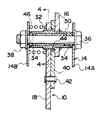
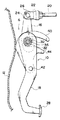
図1には「車両用ペダル」としての吊り下げ式のブレーキペダル10の支持構造が側面視で示されており、又図2には当該ブレーキペダル10の要部縦断面構造が示されており、更に図3には当該ブレーキペダル10の要部を上方側から観た平面構造が示されている。なお、本実施形態に係るブレーキペダル10の支持構造は、フルキャブオーバータイプの車両に対して適用されるものである。
【0017】
これらの図に示されるように、「車体側構成部材」としてのフロントパネル12の車室内側には、ペダルブラケット14(図2及び図3参照)に揺動可能に支持されたブレーキペダル10が配置されている。このブレーキペダル10は、略車両上下方向を長手方向として配置された「第1アーム」としてのペダル上方アーム16と、「第2アーム」としてのペダル下方アーム18とに二分割されている。
【0018】
ペダル上方アーム16の上端部には、「踏力伝達部材」としてのプッシュロッド(オペレーティングロッド)20の先端部が相対回転自在に連結されている。具体的に説明すると、プッシュロッド20の先端部には平面視で略コ字形とされたクレビス22が取り付けられており、このクレビス22の両側部内にペダル上方アーム16の上端部が挿入状態で配置されている。そして、このクレビス22の両側部とペダル上方アーム16の上端部とにクレビスピン24が挿通され、当該クレビスピン24の貫通端部に抜け止め用のβピン26等が挿入係止されることにより、ペダル上方アーム16の上端部とプッシュロッド20の先端部とが相対回転自在に連結されている。
【0019】
なお、プッシュロッド20の基端部はブレーキペダル10に付与された乗員の踏力を増強するための踏力増強手段として機能する図示しないブレーキブースタと連結されており、更にブレーキブースタには当該ブレーキブースタによって増強された圧力を液圧に変換するための液圧変換手段として機能するマスタシリンダ並びに液圧系統の体積変化に追従してブレーキフルードを貯留及び補充するリザーバタンクが一体的に配設されている。
【0020】
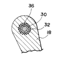
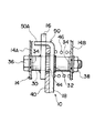
一方、ペダル下方アーム18の下端部には、乗員の踏力が付与される「踏面」としてのペダルパッド28が取り付けられている。また、ペダル下方アーム18の上端部は、ペダルボス30を介してペダル上方アーム16の下端部と係合されている。具体的に説明すると、図2に示されるように、ペダル上方アーム16の下端部には円孔が形成されており、この円孔内へ略円筒状のペダルボス30が圧入されて溶接により固着されている。さらに、ペダルボス30の軸方向中間部にはセレーション32が形成されており、当該セレーション32にペダル下方アーム18の上端部が嵌合されることにより、ペダルボス30とペダル下方アーム18の上端部とが係合されている(図4参照)。
【0021】
なお、ペダルボス30の軸方向両端部には樹脂製のブッシュ34が嵌入されており、更にこれらのブッシュ34内には図示しない樹脂製のカラーが挿入されている。そして、ペダルブラケット14の一方のサイドプレート部14A側からペダルボス30の軸芯部へ「揺動中心軸」としての取付ボルト36が挿入され、他方のサイドプレート部14B側からナット38が螺合されることにより、ブレーキペダル10はペダルボス30を揺動中心として取付ボルト36回りに揺動可能に支持されている。
【0022】
さらに、上述したペダル上方アーム16の下端部側とペダル下方アーム18の上端部側との間には、「解除手段」としての板状の解除レバー40が介在されている。解除レバー40は、側面視で略ε形状を成している。解除レバー40の下端部は、リベット42でペダル下方アーム18の長手方向中間部付近に結合されている。従って、解除レバー40は、リベット42回りに揺動可能にペダル下方アーム18に支持されている。また、解除レバー40の上部側には、後端側から前端側に向かって円弧状に切欠かれた切欠44が形成されている。この切欠44の切欠幅は、ペダルボス30のセレーション32の外径寸法よりも若干大きく設定されている。
【0023】
また、上述したペダル下方アーム18の上端部とペダルブラケット14の他方のサイドプレート部14Bとの間には、圧縮コイルスプリング46が配設されている。この圧縮コイルスプリング46はペダルボス30に巻装されており、一端部は前記他方のサイドプレート部14Bに当接係止され、又他端部はペダル下方アーム18の上端部の側面に当接係止されている。従って、圧縮コイルスプリング46は、ペダル下方アーム18の上端部及び解除レバー40の上部側をこれらの部材がペダル上方アーム16の下端部に密着する方向へ常時押圧付勢している。さらに、図3に示されるように、上述した解除レバー40の上部前端側には、当該解除レバー40の後端側から前端側へ向かうにつれて板厚が増加するテーパ部40Aが形成されている。
【0024】
次に、本実施形態の作用並びに効果について説明する。
【0025】
ブレーキペダル10の通常操作時にあっては、圧縮コイルスプリング46の付勢力によってペダル下方アーム18の上端部はペダルボス30のセレーション32に係合された状態を維持していると共に、ペダルボス30は解除レバー40の切欠44の長手方向中間部付近に位置されている。従って、乗員がペダル下方アーム18のペダルパッド28を踏み込むと、当該ペダル下方アーム18の上端部と係合されたペダルボス30も取付ボルト36回りに同方向へ回転される。このため、ペダルボス30に溶接されたペダル上方アーム16も同方向へ揺動され、これによりプッシュロッド20が略車両後方側へ向けて押圧される。その結果、乗員の踏力はプッシュロッド20を介してブレーキブースタに伝達されて増強された後にマスタシリンダによって液圧に変換される。
【0026】
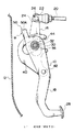
一方、所定値以上の外力が車両前部に作用すると、図5に示されるように、フロントパネル12が略車両後方側へ変位することがある。この場合、フロントパネル12によって解除レバー40の前端部が押圧される。このため、解除レバー40はリベット42回りに略車両後方側へ揺動され、これに伴い図6に示されるように、ペダル上方アーム16の下端部の前端エッジ部が解除レバー40のテーパ部40A上を相対的に摺動していく。これにより、解除レバー40によって、ペダル下方アーム18の上端部が圧縮コイルスプリング46の付勢力に抗してペダル上方アーム16から離間する方向へ変位され、ペダル下方アーム18の上端部とペダルボス30のセレーション32との係合が解除される。すなわち、ペダルボス30のセレーション32を介してペダル下方アーム18に作用していたペダル上方アーム16に対する拘束力が失われる。
【0027】
その結果、所定値以上の外力が車両前部に作用した際にペダル下方アーム18ひいてはペダルパッド28をフリーな状態にすることができ、拘束力を失ったペダル下方アーム18はペダルボス30回りに略車両前方側へ回転変位される。これにより、本実施形態によれば、所定値以上の外力が車両の前方から作用した際における乗員の慣性移動による脚部の膝の屈曲を抑制することができ、ひいては乗員の脚部の膝をステアリングコラムから遠ざけることができる。
【0028】
なお、本実施形態では、ペダル下方アーム18とペダルボス30とを係合させるための構成としてセレーション32を採用したが、これに限らず、図7に示されるような凸歯係合を採用してもよい。簡単に説明すると、ペダルボス30の軸方向中間部には90度間隔でキー状の凸歯48が形成されており、これらの凸歯48をペダル下方アーム18の上端部に嵌合させることにより、ペダル下方アーム18の上端部とペダルボス30とを係合させるようにしてもよい。要は、ペダル下方アーム18の上端部がペダルボス30に対して軸方向に相対移動可能で、かつペダル下方アーム18が揺動された際にはペダルボス30も一体的に回転して当該揺動をペダルボス30を介してペダル上方アーム16に確実に伝達することができる係合手段として把握される構成であればすべて適用可能である。この点は、後述する第2実施形態及び第3実施形態についても同様である。
【0029】
また、本実施形態では、ペダル下方アーム18の上端部をペダルボス30のセレーション32に係合させた状態を維持するべく、狭義には付勢手段として把握される圧縮コイルスプリング46を用いたが、これに限らず、通常時においてはペダル下方アーム18の上端部とペダルボス30との係合状態を保持し、所定値以上の外力が車両前部に作用した際には解除レバー40からの押圧力を受けて当該保持状態を解除し得る保持手段として把握される構成であればすべて適用可能である。例えば、セレーション32の所定部位に形成されたV溝に止め輪を嵌合させたり、自然状態での内径がセレーション32の外径よりも短い所定硬度の筒状の弾性体(ゴムブッシュ等)をセレーション32に被嵌させたり、或るいは、ペダル下方アーム18のペダルボス30への組付後にセレーション32の歯先を適宜間隔である程度潰しておく等の構成を適用することも可能である。この点も、後述する第2実施形態及び第3実施形態についても同様である。
【0030】
さらに、本実施形態では、ペダル上方アーム16の下端部をペダルボス30に溶接により固着して一体化し、当該ペダルボス30にペダル下方アーム18の上端部を通常は係合させて所定値以上の外力が車両前部に作用した際には離脱させる構成を採ったが、これに限らず、逆の構成を採ってもよい。すなわち、ペダル下方アーム18の上端部をペダルボス30に溶接により固着して一体化し、当該ペダルボス30にペダル上方アーム16の下端部を通常は係合させて所定値以上の外力が車両前部に作用した際には離脱させるようにしてもよい。この点は後述する第2実施形態についても同様である。また、後述する第3実施形態では、前記逆の構成が採られている。
〔第2実施形態〕
次に、図8〜図10を用いて、第2実施形態に係るブレーキペダル10の支持構造について説明する。なお、前述した第1実施形態と同一構成部分については、同一番号を付してその説明を省略する。
【0031】
図8及び図9に示されるように、本実施形態では、ペダル下方アーム18の上端部に、正面視でL字形に形成された「規制手段」としての規制部50を設けた点に特徴がある。規制部50の上縁部50Aは、ペダル上方アーム16の中間部の前端面と正面視で重合する程度に延出されている(図9参照)。
【0032】
上記構成によれば、所定値以上の外力が車両前部に作用した際にフロントパネル12の後方変位によって解除レバー40が押圧され、これによりペダル下方アーム18の上端部とペダルボス30のセレーション32との係合を解除してペダル下方アーム18ひいてはペダルパッド28をフリーな状態にする点は、前述した第1実施形態の場合と同様である。
【0033】
ここで、本実施形態では、ペダル下方アーム18の上端部にL字形の規制部50を設けたので、前記の如くペダル下方アーム18がペダルボス30のセレーション32から離脱されると、図10に示されるように、当該規制部50の上縁部50Aがペダル上方アーム16の中間部の前端面に当接する。これにより、ペダル上方アーム16に対するペダル下方アーム18のペダル踏み込み方向への相対変位が規制される。その結果、規制部50によってペダル下方アーム18のペダル踏み込み方向への相対変位が規制された以降は、乗員のペダル操作が可能となり、前記外力作用後に最寄りの整備工場等までの走行を可能にすることができる。
〔第3実施形態〕
次に、図11〜図15を用いて、第3実施形態に係るブレーキペダル60の支持構造について説明する。なお、前述した第1実施形態と同一構成部分については、同一番号を付してその説明を省略する。
【0034】
図11〜図13に示されるように、本実施形態では、第1及び第2実施形態で用いたブレーキペダル支持構造をボンネットタイプの車両、或るいはセミボンネットタイプの車両に適用した点に特徴がある。従って、部品形状及び部品レイアウトが異なるものの、基本的な考え方は前述した各実施形態と同様である。
【0035】
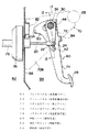
概説すると、図11に示されるように、エンジンルーム62と車室内空間64とを仕切る位置には、「車体側構成部材」としてのダッシュパネル66が略垂直に配置されている。なお、ダッシュパネル66の上端部は略車両幅方向を長手方向として配置されたカウルインナパネルの前端下部に溶接接合されており、又ダッシュパネル66の下端部はフロアパネルに溶接接合されている。
【0036】
ダッシュパネル66の略車両後方側には高強度部材であるパイプ状のインパネリインフォース68が略車両幅方向を長手方向として配置されており、両者の間にペダルブラケット70が掛け渡されている。なお、ペダルブラケット70は下方側が開放された断面コ字形に形成されており、又ペダルブラケット70の一対のサイドプレート部70A、70Bの前部側には略車両前後方向に対する剛性を意図的に低下させるための開口や切欠等が形成されている。
【0037】
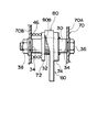
上述したペダルブラケット70の一対のサイドプレート部70A、70B間には、「車両用ペダル」としての吊り下げ式のブレーキペダル60が揺動可能に支持されている。このブレーキペダル60も「第1アーム」としてのペダル上方アーム72と、「第2アーム」としてのペダル下方アーム74とに二分割されており、前述した第1実施形態と同様の係合構成によりペダルボス30を介して相互に連結されている(図12及び図13参照)。但し、本実施形態では、ペダル下方アーム74の上端部がペダルボス30に溶接されて一体化されており、ペダル上方アーム72の上端部がペダルボス30のセレーション32に係合されている。
【0038】
また、この実施形態では、車両レイアウト上の理由から、即ち、エンジンルーム62内におけるペダルブラケット70の前方側にブレーキブースタ76及び「液圧変換手段」としてのマスタシリンダ78等が配設され、当該ブレーキブースタ76からプッシュロッド20がダッシュパネル66を貫通して車室内空間64側へ突出した状態で配置されているため、ペダル上方アーム72はペダルボス30から略車両下方側へ向けて延出されている。なお、ペダル上方アーム72の先端部(この場合、下端部)にプッシュロッド20がクレビス22及びクレビスピン24によって相対回転自在に連結される点は前述した第1実施形態と同様であるが、通常のペダル操作時におけるペダル下方アーム74との干渉を回避するべく、ペダル上方アーム72の先端部側はペダル下方アーム74から離間する方向へクランクされている(図12参照)。
【0039】
さらに、この実施形態では、ペダルボス30からダッシュパネル66までの距離が前述した第1実施形態や第2実施形態の場合よりも長いことから、解除レバー80の前端側にはダッシュパネル66側へ向かって突出する突出部80Aが形成されている。これに対応して、ダッシュパネル66における突出部80Aと対向する位置には、側面視でハット形状の押圧ブラケット82が溶接又は固定具により取り付けられている。なお、この実施形態では、解除レバー80のテーパ部80Bがペダル上方アーム72側の面に形成されているが、機能的には第1実施形態における解除レバー40のテーパ部40Aと同様である。また、本実施形態では、解除レバー80及び押圧ブラケット82が本発明の「解除手段」に相当する。
【0040】
また、ペダル下方アーム74における後端側の所定位置(ペダル上方アーム72と干渉可能な位置)には、平面視でL字形の「規制手段」としての規制部84が一体形成されている。
【0041】
上記構成によれば、ブレーキペダル60の通常操作時にあっては、圧縮コイルスプリング46の付勢力によってペダル上方アーム72の上端部はペダルボス30のセレーション32に係合された状態を維持していると共に、ペダルボス30は解除レバー80の切欠44の長手方向中間部付近に位置されている。従って、乗員がペダル下方アーム74のペダルパッド28を踏み込むと、当該ペダル下方アーム74の上端部と溶接により一体化されたペダルボス30も取付ボルト36回りに同方向へ回転される。このため、ペダルボス30のセレーション32に係合されたペダル上方アーム72も同方向へ揺動され、これによりプッシュロッド20が略車両前方側へ向けて押圧される。その結果、乗員の踏力はプッシュロッド20を介してブレーキブースタ76に伝達された増強された後にマスタシリンダ78によって液圧に変換される。
【0042】
一方、所定値以上の外力が車両前部に作用すると、その際の荷重がマスタシリンダ78及びブレーキブースタ76を介してダッシュパネル66に入力されることがある。この場合、図14に示される如く、ダッシュパネル66は略車両後方側へ変位するのに対し、インパネリインフォース68は高強度であるため略車両後方側へは殆ど変位しない。このため、両者の間に相対変位が生じ、ペダルブラケット70の特に前部側が座屈変形される。
【0043】
また、ダッシュパネル66が略車両後方側へ変位すると、これに伴ってダッシュパネル66に固定されていた押圧ブラケット82も略車両後方側へと変位する。このため、押圧ブラケット82によって解除レバー80の突出部80Aが略車両後方側へ押圧され、解除レバー80をリベット42回りに揺動させる。このため、図15に示される如く、ペダル上方アーム72の上端部の前端エッジ部が解除レバー80のテーパ部80B上を相対的に摺動していく。これにより、解除レバー80によって、ペダル上方アーム72の上端部が圧縮コイルスプリング46の付勢力に抗してペダル下方アーム74から離間する方向へ変位され、ペダル上方アーム72の上端部とペダルボス30のセレーション32との係合が解除される。すなわち、ペダルボス30のセレーション32を介してペダル上方アーム72に作用していたペダル下方アーム74に対する拘束力が失われる。
【0044】
その結果、所定値以上の外力が車両前部に作用した際にペダル下方アーム74ひいてはペダルパッド28をフリーな状態にすることができ、拘束力を失ったペダル下方アーム74はペダルボス30回りに略車両前方側へ回転変位される。従って、本実施形態によっても、前述した第1実施形態と同様に、所定値以上の外力が車両の前方から作用した際における乗員の慣性移動による脚部の膝の屈曲を抑制することができ、ひいては乗員の脚部の膝をステアリングコラムから遠ざけることができる。
【0045】
さらに、本実施形態では、ペダル下方アーム74の後端側にL字形の規制部84を設けたので、前記の如くペダル上方アーム72がペダルボス30のセレーション32から離脱されて略車両前方側へ所定量揺動されると、当該規制部84がペダル上方アーム72の中間部の後端面に当接する。これにより、ペダル上方アーム72に対するペダル下方アーム74のペダル踏み込み方向への相対変位が規制される。その結果、本実施形態によっても、前述した第2実施形態と同様に、規制部84によってペダル下方アーム74のペダル踏み込み方向への相対変位が規制された以降は、乗員のペダル操作が可能となり、前記外力作用後に最寄りの整備工場等までの走行を可能にすることができる。
【0046】
なお、本実施形態では、押圧ブラケット82をダッシュパネル66に取り付ける構成を採ったが、これに限らず、ダッシュパネル66自体に押圧ブラケット82に相当する凸部を一体成形する構成を採ってもよい。
【0047】
以上説明してきた各実施形態では、吊り下げ式の主ブレーキペダルを対象として本発明を適用したが、これに限らず、吊り下げ式のクラッチペダル等の車両用ペダルに対しても本発明は適用可能である。
【0048】
【発明の効果】
以上説明したように、請求項1に記載の本発明に係る車両用ペダル支持構造は、踏力伝達部材側と連結された第1アームと、当該第1アームと揺動中心軸にて係合されると共に踏面を備えた第2アームと、を含んで車両用ペダルを構成し、さらに、揺動中心軸における第1アームと第2アームとの間に、所定値以上の外力が車両前部に作用した際における車体側構成部材の略車両後方側への変位を利用して第2アームを第1アームから離間する方向へ又は第1アームを第2アームから離間する方向へ変位させることで第1アームと第2アームとの係合を解除し、第2アームを第1アームに対して回転フリーな状態にする解除手段を介在させたので、当該外力作用時に第1アームと第2アームとの相互間に作用していた拘束力を失わせることができ、その結果、所定値以上の外力が車両前部に作用した際に車両用ペダルの踏面をフリーな状態にすることができるという優れた効果を有する。
【0049】
請求項2記載の本発明に係る車両用ペダル支持構造は、請求項1に記載の発明において、第1アームと第2アームとの係合が解除された状態において、第2アームが第1アームに対してペダル踏込み方向へ所定量相対変位すると第1アームに干渉して第2アームのそれ以上の相対変位を規制することで乗員のペダル操作を可能とする規制手段を第2アームに設けたので、規制手段によって第1アームに対する第2アームの相対変位が規制された以降は乗員のペダル操作が可能となり、その結果、前記外力作用後に最寄りの整備工場等までの走行を可能にすることができるという優れた効果を有する。
【図面の簡単な説明】
【図1】第1実施形態に係るブレーキペダルの支持構造の全体構成を示す側面図である。
【図2】図1に示されるブレーキペダルの支持構造の要部を示す図1の2−2線に沿う縦断面図である。
【図3】図1に示されるブレーキペダルの支持構造の要部を図1の3線矢視方向から観た平面図である。
【図4】図1に示されるペダル下方アームとペダルボスとの係合構造を示す図2の4−4線に沿う縦断面図である。
【図5】図1に示される状態から所定値以上の外力が車両前部に作用した場合の各部材の挙動を示す側面図である。
【図6】図5に示される状態におけるブレーキペダルの支持構造の要部を図5の6線矢視方向から観た平面図である。
【図7】ペダル下方アームとペダルボスとの係合構造の別の実施形態を示す図4に対応する縦断面図である。
【図8】第2実施形態に係るブレーキペダルの支持構造の全体構成を示す側面図である。
【図9】図8に示されるブレーキペダルの支持構造の要部を図8の9線矢視方向から観た正面図である。
【図10】図8に示される状態から所定値以上の外力が車両前部に作用した場合の各部材の挙動を示す側面図である。
【図11】第3実施形態に係るブレーキペダルの支持構造の全体構成を示す側面図である。
【図12】図11に示されるブレーキペダルの支持構造の要部を示す図11の12−12線に沿う縦断面図である。
【図13】図11に示されるブレーキペダルの支持構造の要部を図11の13線矢視方向から観た平面図である。
【図14】図11に示される状態から所定値以上の外力が車両前部に作用した場合の各部材の挙動を示す側面図である。
【図15】図14に示される状態におけるブレーキペダルの支持構造の要部を図14の15線矢視方向から観た平面図である。
【図16】従来構造を示す斜視図である。
【符号の説明】
10 ブレーキペダル(車両用ペダル)
12 フロントパネル(車体側構成部材)
16 ペダル上方アーム(第1アーム)
18 ペダル下方アーム(第2アーム)
20 プッシュロッド(踏力伝達部材)
28 ペダルパッド(踏面)
36 取付ボルト(揺動中心軸)
40 解除レバー(解除手段)
50 規制部(規制手段)
60 ブレーキペダル(車両用ペダル)
66 ダッシュパネル(車体側構成部材)
72 ペダル上方アーム(第1アーム)
74 ペダル下方アーム(第2アーム)
78 マスタシリンダ(液圧変換手段)
80 解除レバー(解除手段)
82 押圧ブラケット(解除手段)
84 規制部(規制手段)[0001]
BACKGROUND OF THE INVENTION
The present invention is supported via a treading force transmission member that is supported so as to be swingable about a swinging center axis, and swings when a stepping force of an occupant is applied to a tread surface provided at a lower end portion and is connected to a predetermined portion. The present invention relates to a vehicular pedal support structure applied to a vehicular pedal that transmits a pedaling force applied by an occupant to a hydraulic pressure conversion means.
[0002]
[Prior art and problems to be solved by the invention]
Conventionally, various countermeasures have been taken as countermeasures when an external force of a predetermined value or more acts from the front of the vehicle. As an example of this type of countermeasure, the configuration disclosed in Japanese Utility Model Laid-Open No. 1-73464 can be cited.
[0003]
Briefly described, as shown in FIG. 16, in the configuration disclosed in this publication, the
[0004]
Further, a knee protector 412 having a substantially arcuate surface shape and elastically deformable is disposed below the
[0005]
According to the above configuration, when an external force of a predetermined value or more acts from the front of the vehicle, the occupant attempts to move inertially toward the front of the vehicle, and accordingly, the occupant's legs move inertially in the same direction while bending from the knee. try to. For this reason, if the knee protector 412 is not provided, the occupant's knees may come into contact with the
[0006]
Such a configuration in which the knee protector 412 is disposed is also considered to be meaningful as a countermeasure when an external force of a predetermined value or more is applied from the front of the vehicle, but there is another countermeasure in relation to the occupant's legs. It is possible to approach from the viewpoint, and it is important from the viewpoint of multiple protection to establish the countermeasures in a multifaceted relationship with the occupant's legs.
[0007]
As a result of experimenting from such a point of view, the present inventor has found that a brake pedal or the like for a vehicle such as a brake pedal is utilized by utilizing deformation or displacement behavior of a body panel or the like when an external force of a predetermined value or more acts from the front of the vehicle. It came to the conclusion that making the tread surface of the pedal free is also an extremely effective measure.
[0008]
In view of the above knowledge, an object of the present invention is to obtain a vehicular pedal support structure capable of freeing the tread surface of a vehicular pedal when an external force of a predetermined value or more acts on the front portion of the vehicle.
[0009]
[Means for Solving the Problems]
The present invention according to
[0010]
A vehicle pedal support structure according to a second aspect of the present invention is the invention according to the first aspect,The second arm includesIn the state where the engagement between the first arm and the second arm is released,When the second arm is displaced relative to the first arm by a predetermined amount in the pedal depression direction, the second arm interferes with the first arm and restricts the relative displacement beyond that of the second arm, thereby enabling the passenger to operate the pedal.Regulatory measuresIs provided,It is characterized by that.
[0011]
According to the first aspect of the present invention, since the first arm connected to the treading force transmission member side and the second arm having the tread are engaged in the normal state, the occupant is in contact with the tread of the second arm. When the pedal force is applied, the first arm is swung around the swing center axis together with the second arm. As a result, the pedaling force applied by the occupant is transmitted to the hydraulic pressure converting means via the pedaling force transmission member connected to the first arm, and converted into hydraulic pressure.
[0012]
On the other hand, when an external force of a predetermined value or more acts on the front part of the vehicle, the vehicle body side structural member is displaced substantially to the rear side of the vehicle, and this displacement is utilized., Interposed between the first arm and the second arm in the swing center axisBy release meansThe second arm is displaced in a direction away from the first arm or in a direction away from the second arm. ThisThe engagement between the first arm and the second arm is released. For this reason, the restraining force acting between the first arm and the second arm is lost.The second arm is free to rotate with respect to the first arm.
[0013]
The effect | action of this invention of
[0014]
Here, in the present invention described in
[0015]
DETAILED DESCRIPTION OF THE INVENTION
[First Embodiment]
Hereinafter, the support structure of the
[0016]
FIG. 1 shows a support structure of a suspension
[0017]
As shown in these drawings, a
[0018]
A distal end portion of a push rod (operating rod) 20 as a “treading force transmission member” is connected to the upper end portion of the pedal
[0019]
Note that the base end portion of the
[0020]
On the other hand, a
[0021]
In addition,
[0022]
Further, a plate-
[0023]
A
[0024]
Next, the operation and effect of this embodiment will be described.
[0025]
During normal operation of the
[0026]
On the other hand, when an external force of a predetermined value or more acts on the front part of the vehicle, the
[0027]
As a result, when an external force of a predetermined value or more is applied to the front of the vehicle, the pedal
[0028]
In the present embodiment, the
[0029]
In this embodiment, the
[0030]
Furthermore, in this embodiment, the lower end portion of the pedal
[Second Embodiment]
Next, the support structure of the
[0031]
As shown in FIGS. 8 and 9, the present embodiment is characterized in that a
[0032]
According to the above configuration, the
[0033]
Here, in this embodiment, since the L-shaped restricting
[Third Embodiment]
Next, the support structure of the
[0034]
As shown in FIGS. 11 to 13, the present embodiment is characterized in that the brake pedal support structure used in the first and second embodiments is applied to a bonnet type vehicle or a semi-bonnet type vehicle. There is. Therefore, although the component shape and the component layout are different, the basic concept is the same as that of each of the embodiments described above.
[0035]
In general, as shown in FIG. 11, a
[0036]
A pipe-like
[0037]
A suspension
[0038]
In this embodiment, for reasons of vehicle layout, that is, a
[0039]
Furthermore, in this embodiment, since the distance from the
[0040]
Further, at a predetermined position on the rear end side of the pedal lower arm 74 (a position at which the pedal
[0041]
According to the above configuration, during normal operation of the
[0042]
On the other hand, when an external force exceeding a predetermined value acts on the front portion of the vehicle, the load at that time may be input to the
[0043]
Further, when the
[0044]
As a result, when an external force of a predetermined value or more is applied to the front of the vehicle, the pedal
[0045]
Further, in the present embodiment, since the L-shaped restricting
[0046]
In this embodiment, the configuration in which the
[0047]
In each of the embodiments described above, the present invention is applied to a suspension type main brake pedal. However, the present invention is not limited to this, and the present invention is also applied to a vehicle pedal such as a suspension type clutch pedal. Is possible.
[0048]
【The invention's effect】
As described above, the vehicle pedal support structure according to the first aspect of the present invention includes the first arm connected to the pedal force transmission member side, the first arm,At the oscillation center axisA vehicular pedal including a second arm that is engaged and has a tread surface;Between the first arm and the second arm on the swing center axis,Utilizing the displacement of the vehicle body side structural member toward the vehicle rear side when an external force of a predetermined value or more acts on the front part of the vehicleBy displacing the second arm away from the first arm or moving the first arm away from the second armDisengagement between first arm and second armAnd the second arm is in a state of being free to rotate with respect to the first arm.Release meansBecause I intervenedThe restraining force acting between the first arm and the second arm when the external force is applied can be lost, and as a result, when an external force exceeding a predetermined value acts on the front of the vehicle, It has an excellent effect that the tread surface can be made free.
[0049]
A pedal support structure for a vehicle according to a second aspect of the present invention is the vehicle pedal support structure according to the first aspect, wherein the engagement between the first arm and the second arm is released.When the second arm is displaced relative to the first arm by a predetermined amount in the pedal depression direction, the second arm interferes with the first arm and restricts the relative displacement beyond that of the second arm, thereby enabling the passenger to operate the pedal.Regulatory measuresIs provided on the second arm,After the relative displacement of the second arm relative to the first arm is restricted by the restricting means, the occupant can operate the pedal, and as a result, it is possible to travel to the nearest maintenance shop after the external force action. Has an excellent effect.
[Brief description of the drawings]
FIG. 1 is a side view showing an overall configuration of a brake pedal support structure according to a first embodiment.
2 is a longitudinal sectional view taken along line 2-2 of FIG. 1, showing a main part of the brake pedal support structure shown in FIG.
3 is a plan view of the main part of the brake pedal support structure shown in FIG. 1 as viewed from the direction of
4 is a longitudinal sectional view taken along line 4-4 of FIG. 2, showing an engagement structure between a pedal lower arm and a pedal boss shown in FIG.
FIG. 5 is a side view showing the behavior of each member when an external force of a predetermined value or more is applied to the front portion of the vehicle from the state shown in FIG.
6 is a plan view of the main part of the brake pedal support structure in the state shown in FIG. 5 as viewed from the direction of
FIG. 7 is a longitudinal sectional view corresponding to FIG. 4 showing another embodiment of the engagement structure between the pedal lower arm and the pedal boss.
FIG. 8 is a side view showing an overall configuration of a brake pedal support structure according to a second embodiment.
9 is a front view of the main part of the brake pedal support structure shown in FIG. 8 as viewed from the direction of the arrow 9 in FIG. 8;
10 is a side view showing the behavior of each member when an external force of a predetermined value or more is applied to the front portion of the vehicle from the state shown in FIG.
FIG. 11 is a side view showing an overall configuration of a brake pedal support structure according to a third embodiment.
12 is a longitudinal sectional view taken along the line 12-12 in FIG. 11, showing the main part of the brake pedal support structure shown in FIG.
13 is a plan view of the main part of the brake pedal support structure shown in FIG. 11 as viewed from the direction of the
14 is a side view showing the behavior of each member when an external force of a predetermined value or more is applied to the front portion of the vehicle from the state shown in FIG.
15 is a plan view of the essential part of the brake pedal support structure in the state shown in FIG. 14 as viewed from the direction of the
FIG. 16 is a perspective view showing a conventional structure.
[Explanation of symbols]
10 Brake pedal (vehicle pedal)
12 Front panel (body-side component)
16 Pedal upper arm (first arm)
18 Pedal lower arm (second arm)
20 Push rod (treading force transmission member)
28 Pedal pad (tread)
36 Mounting bolt (Oscillation center axis)
40 Release lever (release means)
50 Regulatory department (regulatory means)
60 Brake pedal (vehicle pedal)
66 Dash panel (vehicle body side component)
72 Pedal upper arm (first arm)
74 Pedal lower arm (second arm)
78 Master cylinder (hydraulic pressure conversion means)
80 Release lever (release means)
82 Pressing bracket (Release means)
84 Regulations (regulatory means)
Claims (2)
前記車両用ペダルは、踏力伝達部材側と連結された第1アームと、当該第1アームと揺動中心軸にて係合されると共に踏面を備えた第2アームと、を含んで構成され、
さらに、揺動中心軸における第1アームと第2アームとの間には、所定値以上の外力が車両前部に作用した際における車体側構成部材の略車両後方側への変位を利用して第2アームを第1アームから離間する方向へ又は第1アームを第2アームから離間する方向へ変位させることで第1アームと第2アームとの係合を解除し、第2アームを第1アームに対して回転フリーな状態にする解除手段が介在されている、
ことを特徴とする車両用ペダル支持構造。The occupant is supported through a treading force transmission member that is supported by the occupant's treading force and is coupled to a predetermined portion by being supported by the treading surface provided at the lower end portion so that the treading force of the occupant is applied. A pedal support structure for a vehicle that is applied to a pedal for the vehicle that transmits the pedaling force to the hydraulic pressure conversion means,
The vehicle pedal includes a first arm connected to the pedal force transmission member side, and a second arm that is engaged with the first arm at the swing center axis and includes a tread surface,
Further, between the first arm and the second arm on the swing center axis , the displacement of the vehicle body side structural member to the substantially rear side of the vehicle when an external force of a predetermined value or more is applied to the front of the vehicle is utilized. By disengaging the second arm in the direction away from the first arm or in the direction away from the second arm, the engagement between the first arm and the second arm is released , and the second arm is moved to the first arm. A release means is provided to make the rotation free state with respect to the arm ,
A pedal support structure for a vehicle.
ことを特徴とする請求項1に記載の車両用ペダル支持構造。 In the state where the engagement between the first arm and the second arm is released, the second arm interferes with the first arm when the second arm is displaced by a predetermined amount in the pedal depression direction with respect to the first arm. A restricting means is provided that allows the occupant to operate the pedal by restricting further relative displacement of the second arm .
The vehicle pedal support structure according to claim 1.
Priority Applications (1)
| Application Number | Priority Date | Filing Date | Title |
|---|---|---|---|
| JP11104898A JP3671668B2 (en) | 1998-04-21 | 1998-04-21 | Pedal support structure for vehicles |
Applications Claiming Priority (1)
| Application Number | Priority Date | Filing Date | Title |
|---|---|---|---|
| JP11104898A JP3671668B2 (en) | 1998-04-21 | 1998-04-21 | Pedal support structure for vehicles |
Publications (2)
| Publication Number | Publication Date |
|---|---|
| JPH11301431A JPH11301431A (en) | 1999-11-02 |
| JP3671668B2 true JP3671668B2 (en) | 2005-07-13 |
Family
ID=14551095
Family Applications (1)
| Application Number | Title | Priority Date | Filing Date |
|---|---|---|---|
| JP11104898A Expired - Lifetime JP3671668B2 (en) | 1998-04-21 | 1998-04-21 | Pedal support structure for vehicles |
Country Status (1)
| Country | Link |
|---|---|
| JP (1) | JP3671668B2 (en) |
Families Citing this family (4)
| Publication number | Priority date | Publication date | Assignee | Title |
|---|---|---|---|---|
| DE10040270C2 (en) * | 2000-08-17 | 2002-09-26 | Edscha Ag | Safety device in the pedal area for a car |
| JP4858806B2 (en) * | 2005-07-01 | 2012-01-18 | スズキ株式会社 | Pedal device |
| JP5921900B2 (en) * | 2012-02-06 | 2016-05-24 | 三菱自動車工業株式会社 | Pedal device |
| JP2023164181A (en) * | 2022-04-29 | 2023-11-10 | 株式会社デンソー | brake pedal device |
-
1998
- 1998-04-21 JP JP11104898A patent/JP3671668B2/en not_active Expired - Lifetime
Also Published As
| Publication number | Publication date |
|---|---|
| JPH11301431A (en) | 1999-11-02 |
Similar Documents
| Publication | Publication Date | Title |
|---|---|---|
| JP3277814B2 (en) | Vehicle pedal displacement control structure | |
| EP0805079B1 (en) | Pedal support structure for a vehicle | |
| JP3239751B2 (en) | Vehicle pedal support structure | |
| JP4466659B2 (en) | Pedal support structure for vehicles | |
| JP3449206B2 (en) | Vehicle pedal displacement control structure | |
| JPH11139346A (en) | Vehicular pedal displacement control structure | |
| EP1510426B1 (en) | Automotive pedal support structure | |
| JP3671668B2 (en) | Pedal support structure for vehicles | |
| JP3239790B2 (en) | Vehicle pedal displacement control structure | |
| JPH1143073A (en) | Vehicle pedal displacement control structure | |
| JP4120528B2 (en) | Brake arrangement structure for vehicles | |
| JP3932702B2 (en) | Pedal bracket structure | |
| JP3856272B2 (en) | Pedal bracket structure | |
| JP2008225666A (en) | Vehicular pedal displacement control structure | |
| JP2959235B2 (en) | Pedal device | |
| JPH1159351A (en) | Vehicular pedal displacement control structure | |
| JPH11268667A (en) | Structure for controlling displacement of pedal for vehicle | |
| JPH10236288A (en) | Pedal supporting structure for vehicle | |
| WO2020250562A1 (en) | Operative pedal device for vehicle | |
| JP3804651B2 (en) | Pedal displacement control structure for vehicles | |
| JP3269412B2 (en) | Vehicle pedal support structure | |
| JP3267891B2 (en) | Vehicle pedal displacement control structure | |
| JPH10264859A (en) | Pedal supporting structure of vehicle | |
| KR100986497B1 (en) | protective device of automobile driver | |
| JP3236555B2 (en) | Vehicle release structure |
Legal Events
| Date | Code | Title | Description |
|---|---|---|---|
| A977 | Report on retrieval |
Free format text: JAPANESE INTERMEDIATE CODE: A971007 Effective date: 20040701 |
|
| A131 | Notification of reasons for refusal |
Free format text: JAPANESE INTERMEDIATE CODE: A131 Effective date: 20040720 |
|
| A521 | Written amendment |
Free format text: JAPANESE INTERMEDIATE CODE: A523 Effective date: 20040916 |
|
| TRDD | Decision of grant or rejection written | ||
| A01 | Written decision to grant a patent or to grant a registration (utility model) |
Free format text: JAPANESE INTERMEDIATE CODE: A01 Effective date: 20050329 |
|
| A61 | First payment of annual fees (during grant procedure) |
Free format text: JAPANESE INTERMEDIATE CODE: A61 Effective date: 20050411 |
|
| R150 | Certificate of patent or registration of utility model |
Free format text: JAPANESE INTERMEDIATE CODE: R150 |
|
| FPAY | Renewal fee payment (event date is renewal date of database) |
Free format text: PAYMENT UNTIL: 20090428 Year of fee payment: 4 |
|
| FPAY | Renewal fee payment (event date is renewal date of database) |
Free format text: PAYMENT UNTIL: 20090428 Year of fee payment: 4 |
|
| FPAY | Renewal fee payment (event date is renewal date of database) |
Free format text: PAYMENT UNTIL: 20100428 Year of fee payment: 5 |
|
| FPAY | Renewal fee payment (event date is renewal date of database) |
Free format text: PAYMENT UNTIL: 20100428 Year of fee payment: 5 |
|
| FPAY | Renewal fee payment (event date is renewal date of database) |
Free format text: PAYMENT UNTIL: 20110428 Year of fee payment: 6 |
|
| FPAY | Renewal fee payment (event date is renewal date of database) |
Free format text: PAYMENT UNTIL: 20120428 Year of fee payment: 7 |
|
| FPAY | Renewal fee payment (event date is renewal date of database) |
Free format text: PAYMENT UNTIL: 20120428 Year of fee payment: 7 |
|
| FPAY | Renewal fee payment (event date is renewal date of database) |
Free format text: PAYMENT UNTIL: 20130428 Year of fee payment: 8 |
|
| FPAY | Renewal fee payment (event date is renewal date of database) |
Free format text: PAYMENT UNTIL: 20140428 Year of fee payment: 9 |
|
| EXPY | Cancellation because of completion of term |