WO2020246465A1 - レンズ駆動装置、カメラモジュール、及びカメラ搭載装置 - Google Patents
レンズ駆動装置、カメラモジュール、及びカメラ搭載装置 Download PDFInfo
- Publication number
- WO2020246465A1 WO2020246465A1 PCT/JP2020/021770 JP2020021770W WO2020246465A1 WO 2020246465 A1 WO2020246465 A1 WO 2020246465A1 JP 2020021770 W JP2020021770 W JP 2020021770W WO 2020246465 A1 WO2020246465 A1 WO 2020246465A1
- Authority
- WO
- WIPO (PCT)
- Prior art keywords
- ois
- lens
- optical axis
- stage
- unit
- Prior art date
Links
- 230000003287 optical effect Effects 0.000 claims abstract description 58
- 230000033001 locomotion Effects 0.000 claims abstract description 47
- 230000004044 response Effects 0.000 claims abstract description 6
- 125000006850 spacer group Chemical group 0.000 claims description 49
- 238000003384 imaging method Methods 0.000 claims description 10
- 230000002093 peripheral effect Effects 0.000 claims description 9
- 238000012545 processing Methods 0.000 claims description 3
- 238000000034 method Methods 0.000 claims description 2
- 230000005389 magnetism Effects 0.000 abstract description 6
- 230000000694 effects Effects 0.000 abstract 1
- 230000005540 biological transmission Effects 0.000 description 34
- 230000006399 behavior Effects 0.000 description 12
- 229920001230 polyarylate Polymers 0.000 description 9
- 239000000758 substrate Substances 0.000 description 7
- 238000012937 correction Methods 0.000 description 6
- 238000010586 diagram Methods 0.000 description 6
- 229920000106 Liquid crystal polymer Polymers 0.000 description 5
- 239000004977 Liquid-crystal polymers (LCPs) Substances 0.000 description 5
- 238000001514 detection method Methods 0.000 description 5
- 230000009977 dual effect Effects 0.000 description 5
- 229910045601 alloy Inorganic materials 0.000 description 2
- 239000000956 alloy Substances 0.000 description 2
- 229910010293 ceramic material Inorganic materials 0.000 description 2
- 239000004020 conductor Substances 0.000 description 2
- 239000000463 material Substances 0.000 description 2
- 238000000465 moulding Methods 0.000 description 2
- 239000011347 resin Substances 0.000 description 2
- 229920005989 resin Polymers 0.000 description 2
- 230000006641 stabilisation Effects 0.000 description 2
- 238000011105 stabilization Methods 0.000 description 2
- 229910052727 yttrium Inorganic materials 0.000 description 2
- 238000013459 approach Methods 0.000 description 1
- DMFGNRRURHSENX-UHFFFAOYSA-N beryllium copper Chemical compound [Be].[Cu] DMFGNRRURHSENX-UHFFFAOYSA-N 0.000 description 1
- 230000000295 complement effect Effects 0.000 description 1
- YOCUPQPZWBBYIX-UHFFFAOYSA-N copper nickel Chemical compound [Ni].[Cu] YOCUPQPZWBBYIX-UHFFFAOYSA-N 0.000 description 1
- 230000001771 impaired effect Effects 0.000 description 1
- 239000007769 metal material Substances 0.000 description 1
- 229910044991 metal oxide Inorganic materials 0.000 description 1
- 150000004706 metal oxides Chemical class 0.000 description 1
- 238000012986 modification Methods 0.000 description 1
- 230000004048 modification Effects 0.000 description 1
- 239000012778 molding material Substances 0.000 description 1
- 239000004065 semiconductor Substances 0.000 description 1
- 239000010935 stainless steel Substances 0.000 description 1
- 229910001220 stainless steel Inorganic materials 0.000 description 1
Images


Classifications
-
- G—PHYSICS
- G02—OPTICS
- G02B—OPTICAL ELEMENTS, SYSTEMS OR APPARATUS
- G02B7/00—Mountings, adjusting means, or light-tight connections, for optical elements
- G02B7/003—Alignment of optical elements
- G02B7/005—Motorised alignment
-
- H—ELECTRICITY
- H04—ELECTRIC COMMUNICATION TECHNIQUE
- H04N—PICTORIAL COMMUNICATION, e.g. TELEVISION
- H04N23/00—Cameras or camera modules comprising electronic image sensors; Control thereof
- H04N23/50—Constructional details
- H04N23/54—Mounting of pick-up tubes, electronic image sensors, deviation or focusing coils
-
- G—PHYSICS
- G03—PHOTOGRAPHY; CINEMATOGRAPHY; ANALOGOUS TECHNIQUES USING WAVES OTHER THAN OPTICAL WAVES; ELECTROGRAPHY; HOLOGRAPHY
- G03B—APPARATUS OR ARRANGEMENTS FOR TAKING PHOTOGRAPHS OR FOR PROJECTING OR VIEWING THEM; APPARATUS OR ARRANGEMENTS EMPLOYING ANALOGOUS TECHNIQUES USING WAVES OTHER THAN OPTICAL WAVES; ACCESSORIES THEREFOR
- G03B5/00—Adjustment of optical system relative to image or object surface other than for focusing
- G03B5/02—Lateral adjustment of lens
-
- G—PHYSICS
- G02—OPTICS
- G02B—OPTICAL ELEMENTS, SYSTEMS OR APPARATUS
- G02B27/00—Optical systems or apparatus not provided for by any of the groups G02B1/00 - G02B26/00, G02B30/00
- G02B27/64—Imaging systems using optical elements for stabilisation of the lateral and angular position of the image
- G02B27/646—Imaging systems using optical elements for stabilisation of the lateral and angular position of the image compensating for small deviations, e.g. due to vibration or shake
-
- G—PHYSICS
- G02—OPTICS
- G02B—OPTICAL ELEMENTS, SYSTEMS OR APPARATUS
- G02B7/00—Mountings, adjusting means, or light-tight connections, for optical elements
- G02B7/02—Mountings, adjusting means, or light-tight connections, for optical elements for lenses
- G02B7/023—Mountings, adjusting means, or light-tight connections, for optical elements for lenses permitting adjustment
-
- G—PHYSICS
- G02—OPTICS
- G02B—OPTICAL ELEMENTS, SYSTEMS OR APPARATUS
- G02B7/00—Mountings, adjusting means, or light-tight connections, for optical elements
- G02B7/02—Mountings, adjusting means, or light-tight connections, for optical elements for lenses
- G02B7/04—Mountings, adjusting means, or light-tight connections, for optical elements for lenses with mechanism for focusing or varying magnification
- G02B7/08—Mountings, adjusting means, or light-tight connections, for optical elements for lenses with mechanism for focusing or varying magnification adapted to co-operate with a remote control mechanism
-
- G—PHYSICS
- G03—PHOTOGRAPHY; CINEMATOGRAPHY; ANALOGOUS TECHNIQUES USING WAVES OTHER THAN OPTICAL WAVES; ELECTROGRAPHY; HOLOGRAPHY
- G03B—APPARATUS OR ARRANGEMENTS FOR TAKING PHOTOGRAPHS OR FOR PROJECTING OR VIEWING THEM; APPARATUS OR ARRANGEMENTS EMPLOYING ANALOGOUS TECHNIQUES USING WAVES OTHER THAN OPTICAL WAVES; ACCESSORIES THEREFOR
- G03B15/00—Special procedures for taking photographs; Apparatus therefor
-
- G—PHYSICS
- G03—PHOTOGRAPHY; CINEMATOGRAPHY; ANALOGOUS TECHNIQUES USING WAVES OTHER THAN OPTICAL WAVES; ELECTROGRAPHY; HOLOGRAPHY
- G03B—APPARATUS OR ARRANGEMENTS FOR TAKING PHOTOGRAPHS OR FOR PROJECTING OR VIEWING THEM; APPARATUS OR ARRANGEMENTS EMPLOYING ANALOGOUS TECHNIQUES USING WAVES OTHER THAN OPTICAL WAVES; ACCESSORIES THEREFOR
- G03B17/00—Details of cameras or camera bodies; Accessories therefor
- G03B17/02—Bodies
- G03B17/12—Bodies with means for supporting objectives, supplementary lenses, filters, masks, or turrets
-
- G—PHYSICS
- G03—PHOTOGRAPHY; CINEMATOGRAPHY; ANALOGOUS TECHNIQUES USING WAVES OTHER THAN OPTICAL WAVES; ELECTROGRAPHY; HOLOGRAPHY
- G03B—APPARATUS OR ARRANGEMENTS FOR TAKING PHOTOGRAPHS OR FOR PROJECTING OR VIEWING THEM; APPARATUS OR ARRANGEMENTS EMPLOYING ANALOGOUS TECHNIQUES USING WAVES OTHER THAN OPTICAL WAVES; ACCESSORIES THEREFOR
- G03B3/00—Focusing arrangements of general interest for cameras, projectors or printers
-
- G—PHYSICS
- G03—PHOTOGRAPHY; CINEMATOGRAPHY; ANALOGOUS TECHNIQUES USING WAVES OTHER THAN OPTICAL WAVES; ELECTROGRAPHY; HOLOGRAPHY
- G03B—APPARATUS OR ARRANGEMENTS FOR TAKING PHOTOGRAPHS OR FOR PROJECTING OR VIEWING THEM; APPARATUS OR ARRANGEMENTS EMPLOYING ANALOGOUS TECHNIQUES USING WAVES OTHER THAN OPTICAL WAVES; ACCESSORIES THEREFOR
- G03B30/00—Camera modules comprising integrated lens units and imaging units, specially adapted for being embedded in other devices, e.g. mobile phones or vehicles
-
- H—ELECTRICITY
- H02—GENERATION; CONVERSION OR DISTRIBUTION OF ELECTRIC POWER
- H02N—ELECTRIC MACHINES NOT OTHERWISE PROVIDED FOR
- H02N2/00—Electric machines in general using piezoelectric effect, electrostriction or magnetostriction
- H02N2/02—Electric machines in general using piezoelectric effect, electrostriction or magnetostriction producing linear motion, e.g. actuators; Linear positioners ; Linear motors
- H02N2/028—Electric machines in general using piezoelectric effect, electrostriction or magnetostriction producing linear motion, e.g. actuators; Linear positioners ; Linear motors along multiple or arbitrary translation directions, e.g. XYZ stages
-
- H—ELECTRICITY
- H02—GENERATION; CONVERSION OR DISTRIBUTION OF ELECTRIC POWER
- H02N—ELECTRIC MACHINES NOT OTHERWISE PROVIDED FOR
- H02N2/00—Electric machines in general using piezoelectric effect, electrostriction or magnetostriction
- H02N2/02—Electric machines in general using piezoelectric effect, electrostriction or magnetostriction producing linear motion, e.g. actuators; Linear positioners ; Linear motors
- H02N2/04—Constructional details
-
- H—ELECTRICITY
- H02—GENERATION; CONVERSION OR DISTRIBUTION OF ELECTRIC POWER
- H02N—ELECTRIC MACHINES NOT OTHERWISE PROVIDED FOR
- H02N2/00—Electric machines in general using piezoelectric effect, electrostriction or magnetostriction
- H02N2/10—Electric machines in general using piezoelectric effect, electrostriction or magnetostriction producing rotary motion, e.g. rotary motors
- H02N2/12—Constructional details
-
- H—ELECTRICITY
- H04—ELECTRIC COMMUNICATION TECHNIQUE
- H04N—PICTORIAL COMMUNICATION, e.g. TELEVISION
- H04N23/00—Cameras or camera modules comprising electronic image sensors; Control thereof
-
- H—ELECTRICITY
- H04—ELECTRIC COMMUNICATION TECHNIQUE
- H04N—PICTORIAL COMMUNICATION, e.g. TELEVISION
- H04N23/00—Cameras or camera modules comprising electronic image sensors; Control thereof
- H04N23/50—Constructional details
- H04N23/55—Optical parts specially adapted for electronic image sensors; Mounting thereof
-
- H—ELECTRICITY
- H04—ELECTRIC COMMUNICATION TECHNIQUE
- H04N—PICTORIAL COMMUNICATION, e.g. TELEVISION
- H04N23/00—Cameras or camera modules comprising electronic image sensors; Control thereof
- H04N23/57—Mechanical or electrical details of cameras or camera modules specially adapted for being embedded in other devices
-
- H—ELECTRICITY
- H04—ELECTRIC COMMUNICATION TECHNIQUE
- H04N—PICTORIAL COMMUNICATION, e.g. TELEVISION
- H04N23/00—Cameras or camera modules comprising electronic image sensors; Control thereof
- H04N23/60—Control of cameras or camera modules
-
- H—ELECTRICITY
- H04—ELECTRIC COMMUNICATION TECHNIQUE
- H04N—PICTORIAL COMMUNICATION, e.g. TELEVISION
- H04N23/00—Cameras or camera modules comprising electronic image sensors; Control thereof
- H04N23/60—Control of cameras or camera modules
- H04N23/68—Control of cameras or camera modules for stable pick-up of the scene, e.g. compensating for camera body vibrations
- H04N23/682—Vibration or motion blur correction
- H04N23/685—Vibration or motion blur correction performed by mechanical compensation
- H04N23/687—Vibration or motion blur correction performed by mechanical compensation by shifting the lens or sensor position
Definitions
- the present invention relates to a lens driving device, a camera module, and a camera mounting device.
- AF function Autofocus function
- OIS function Optical Image Stabilization
- a lens drive device having an AF function and an OIS function has an autofocus drive unit (hereinafter referred to as "AF drive unit”) for moving the lens unit in the optical axis direction and a plane in which the lens unit is orthogonal to the optical axis direction. It is provided with a runout correction drive unit (hereinafter referred to as “OIS drive unit”) for swinging the lens.
- AF drive unit autofocus drive unit
- OIS drive unit runout correction drive unit
- a voice coil motor (VCM) is applied to the AF drive unit and the OIS drive unit.
- a camera module having a plurality of (typically two) lens driving devices has been put into practical use (so-called dual camera).
- the dual camera has various possibilities depending on the usage scene, such as being able to simultaneously capture two images having different focal lengths and being able to simultaneously capture a still image and a moving image.
- a lens driving device using VCM is affected by external magnetism, so that high-precision operation may be impaired.
- a lens driving device using VCM is affected by external magnetism, so that high-precision operation may be impaired.
- magnetic interference will occur between the lens driving devices.
- Patent Document 2 discloses a lens driving device in which an ultrasonic motor is applied to an AF driving unit and an OIS driving unit. Since the lens driving device disclosed in Patent Document 2 is magnetless, the influence of external magnetism can be reduced, but the structure is complicated, and it is difficult to reduce the size and height.
- An object of the present invention is to provide a lens driving device, a camera module, and a camera-mounted device capable of reducing the influence of external magnetism, as well as reducing the size and height.
- the lens driving device is 1st fixed part and A first movable portion having a lens holder for holding the lens portion and arranged apart from the first fixed portion, A first support portion that supports the first movable portion with respect to the first fixed portion, It is a lens driving device that is composed of an ultrasonic motor that converts vibrational motion into linear motion, and includes a Z-direction drive unit for moving the first movable portion in the optical axis direction with respect to the first fixed portion.
- a rotating body that rotates around the optical axis in response to the linear motion of the Z-direction drive unit, It has a mechanical element that converts the rotational motion of the rotating body into the linear motion in the optical axis direction. As the rotating body rotates, the first movable portion moves in the optical axis direction.
- the camera module With the above lens drive
- the lens portion attached to the first movable portion and It includes an imaging unit that captures a subject image imaged by the lens unit.
- the camera-mounted device A camera-mounted device that is an information device or a transportation device. With the above camera module It includes an image processing unit that processes the image information obtained by the camera module.
- a lens driving device a camera module, and a camera-mounted device that can reduce the influence of external magnetism and can reduce the size and height.
- FIG. 1A and 1B are diagrams showing a smartphone equipped with a camera module according to an embodiment of the present invention.
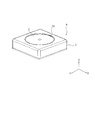
- FIG. 2 is an external perspective view of the camera module.
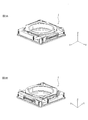
- 3A and 3B are external perspective views of the lens driving device.
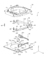
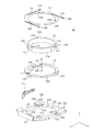
- FIG. 4 is an exploded perspective view of the lens driving device.
- FIG. 5 is an exploded perspective view of the lens driving device.
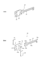
- 6A and 6B are perspective views of the first OIS drive unit.
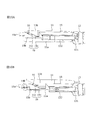
- FIG. 7 is an exploded perspective view of the OIS movable portion.
- FIG. 8 is an exploded perspective view of the OIS movable portion.
- FIG. 9 is a perspective view of the AF drive unit.
- 10A and 10B are diagrams showing the behavior of the lens holder with the rotation of the rotating spacer.
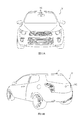
- 11A and 11B are diagrams showing an automobile as a camera-mounted device for mounting an in-vehicle camera module.
- FIG. 1A and 1B are diagrams showing a smartphone M (an example of a camera-mounted device) equipped with a camera module A according to an embodiment of the present invention.
- FIG. 1A is a front view of the smartphone M
- FIG. 1B is a rear view of the smartphone M.
- the smartphone M has a dual camera including two rear cameras OC1 and OC2.
- the camera module A is applied to the rear cameras OC1 and OC2.
- the camera module A has an AF function and an OIS function, automatically adjusts the focus when shooting a subject, and optically corrects the shake (vibration) that occurs during shooting to shoot an image without image blur. be able to.
- FIG. 2 is an external perspective view of the camera module A.
- 3A and 3B are external perspective views of the lens driving device 1.
- FIG. 3B shows a state in which FIG. 3A is rotated by 180 ° around the Z axis.
- the present embodiment will be described using a Cartesian coordinate system (X, Y, Z). Also in the figure described later, it is shown by a common Cartesian coordinate system (X, Y, Z).
- the X direction is the vertical direction (or the horizontal direction)
- the Y direction is the horizontal direction (or the vertical direction)
- the Z direction is the front-back direction. It will be installed. That is, the Z direction is the optical axis direction, the upper side (+ Z side) in the figure is the optical axis direction light receiving side (subject side), and the lower side ( ⁇ Z side) is the optical axis direction imaging side.
- the X direction and the Y direction are "optical axis orthogonal directions" orthogonal to the Z axis
- the XY plane is an "optical axis orthogonal plane” orthogonal to the optical axis.
- the camera module A is imaged by a lens driving device 1 that realizes an AF function and an OIS function, a lens unit 2 in which a lens is housed in a cylindrical lens barrel, and a lens unit 2. It includes an imaging unit (not shown) that captures a subject image, a cover 3 that covers the entire image, and the like.
- the cover 3 is a covered square cylinder having a rectangular shape when viewed from the optical axis direction.
- the cover 3 has a square shape in a plan view.
- the cover 3 has a substantially circular opening 3a on the upper surface.
- the lens portion 2 is configured to face the outside from the opening 3a and project toward the light receiving side from the opening surface of the cover 3 as it moves in the optical axis direction.
- the cover 3 is fixed to the OIS fixing portion 20 (see FIG. 4) of the lens driving device 1, for example, by adhesion.
- the imaging unit (not shown) is arranged on the optical axis direction imaging side of the lens driving device 1.
- the image pickup unit (not shown) has, for example, an image sensor substrate and an image pickup element mounted on the image sensor substrate.
- the image sensor is composed of, for example, a CCD (charge-coupled device) type image sensor, a CMOS (complementary metal oxide semiconductor) type image sensor, and the like.
- the image sensor captures a subject image imaged by the lens unit 2.
- the lens driving device 1 is mounted on an image sensor substrate (not shown) and is mechanically and electrically connected.
- the control unit that controls the drive of the lens driving device 1 may be provided on the image sensor substrate, or may be provided on the camera-mounted device (smartphone M in the present embodiment) on which the camera module A is mounted. ..
- FIGS. 4 and 5 are exploded perspective views of the lens driving device 1.
- FIG. 5 shows a state in which FIG. 4 is rotated by 90 ° around the Z axis and viewed from below.
- the lens driving device 1 includes an OIS movable portion 10 (second movable portion), an OIS fixing portion 20 (second fixed portion), and an OIS driving unit 30 (XY).
- a directional drive unit), an OIS support unit 40 (second support unit), and the like are provided.
- the OIS movable portion 10 is a portion that swings in the plane orthogonal to the optical axis during image stabilization.
- the OIS movable portion 10 includes an AF movable portion 11 (first movable portion), a first stage 12 (first fixed portion), an AF drive portion 13 (Z direction drive portion), an AF support portion 14 (first support portion), and It includes an AF unit having a rotating spacer 15 (see FIG. 7 and the like).
- the OIS fixing portion 20 is a portion to which the OIS movable portion 10 is connected via the OIS support portion 40.
- the OIS fixing portion 20 includes a base 21.
- the OIS support portion 40 supports the OIS movable portion 10 with respect to the OIS fixing portion 20 in a state of being separated in the optical axis direction.
- the OIS support portion 40 includes a second stage 41X, 41Y, balls 42, 43 and an OIS urging member 44.
- the OIS movable portion 10 is arranged at a distance from the OIS fixing portion 20 in the optical axis direction, and is connected to the OIS fixing portion 20 via the OIS support portion 40. Further, the OIS movable portion 10 and the OIS fixing portion 20 are urged in a direction approaching each other by OIS urging members 44 arranged at four locations on the outer peripheral surface of the OIS movable portion 10.
- the OIS movable portion 10 can be swung accurately in the XY plane. It has become.
- the number of balls 42, 43 constituting the OIS support portion 40 can be changed as appropriate.
- the base 21 is formed of, for example, a molding material made of polyarylate (PAR), a PAR alloy (for example, PAR / PC) in which a plurality of resin materials containing PAR are mixed, or a liquid crystal polymer (LCP). It is a member having a rectangular shape in a plan view, and has a circular opening 21a in the center.
- the base 21 has an OIS motor fixing portion 21b in which the OIS driving portion 30 is arranged at two corner portions.
- the OIS motor fixing portion 21b is formed so as to project from the main surface of the base 21 toward the light receiving side in the optical axis direction, and has a shape capable of holding the OIS drive portion 30.
- terminal fittings and wiring are arranged on the base 21 by, for example, insert molding. Further, a sensor substrate on which Hall elements 51X and 51Y are mounted is arranged on the base 21.
- the wiring includes a power supply line to the AF drive unit 13 (see FIG. 7 and the like) and the OIS drive unit 30. The wiring is exposed from the peripheral edge of the base 21, for example, and is electrically connected to the wiring formed on the sensor substrate and the OIS urging member 44.
- the base 21 has ball accommodating portions 21c, 21d, 21e for accommodating the balls 42.
- the ball accommodating portion 21c is formed by being recessed in a circular shape, and accommodates the balls 42 interposed between the base 21 and the first stage 12.
- the ball accommodating portion 21d is formed by being recessed in a rectangular shape extending in the X direction, and accommodates the ball 42 interposed between the base 21 and the second stage 41X.
- the ball accommodating portion 21e is formed by being recessed in a rectangular shape extending in the Y direction, and accommodates the ball 42 interposed between the base 21 and the second stage 41Y.
- the side surfaces of the ball accommodating portions 21d and 21e are formed in a tapered shape so that the groove width becomes narrower toward the bottom surface side, for example.
- the sensor board (not shown) has wiring (not shown) including a power supply line and a signal line for Hall elements 51X and 51Y.
- the Hall elements 51X and 51Y are electrically connected to the wiring (not shown) of the base 21 via the wiring (not shown) formed on the sensor substrate.
- magnets 52X and 52Y are arranged at positions facing the Hall elements 51X and 51Y. The positions of the OIS movable portion 10 in the X direction and the Y direction are detected by the XY position detection unit including the Hall elements 51X and 51Y and the magnets 52X and 52Y.
- the second stages 41X and 41Y are formed of, for example, a liquid crystal polymer and have an L-shape as a whole.
- the inner peripheral surfaces of the second stages 41X and 41Y are formed in an arc shape along the outer shape of the lens holder 11.
- the second stages 41X and 41Y are arranged along the X direction and the Y direction, respectively. Further, the adjacent portions are separated from each other at a predetermined interval so that the second stages 41X and 41Y can move independently of each other.
- the outer surfaces of the second stages 41X and 41Y are recessed inward so that the OIS drive units 30X and 30Y are located when the lens drive device 1 is assembled.
- the second stages 41X and 41Y are formed in an L shape as a whole, and the second stages 41X and 41Y are arranged below the thinly formed portion in the first stage 12. The height of the OIS movable portion 10 is reduced.
- Engagement pieces 41e and 41f protruding toward the light receiving side in the optical axis direction are provided on the peripheral edges of the second stages 41X and 41Y.
- One end of the OIS power transmission unit 33 is fixed to the engaging pieces 41e and 41f. Further, the engaging pieces 41e and 41f are loosely fitted into the engaging grooves 12g and 12h provided in the first stage 12.
- the engaging piece 41e and the engaging groove 12g are engaged to the extent that at least the surfaces facing each other in the Y direction do not abut when the first stage 12 moves in the Y direction, and the engaging piece 41f And the engagement groove 12h are engaged with each other to the extent that the surfaces facing each other in the Y direction do not come into contact with each other at least when the first stage 12 moves in the Y direction. That is, even if the first stage 12 moves in the Y direction, the second stage 41X is not displaced, and even if the first stage 12 moves in the X direction, the second stage 41Y is not displaced.
- Each of the second stages 41X and 41Y has three ball accommodating portions 41a and 41b accommodating the balls 42 on the lower surface (the surface on the optical axis direction imaging side).
- the ball accommodating portion 41a faces the ball accommodating portions 21d and 21e of the base 21.
- the ball accommodating portions 41a and 41b are formed by being recessed in an oval shape extending in the X direction and the Y direction, respectively. Further, the side surfaces of the ball accommodating portions 41a and 41b are formed in a tapered shape so that the groove width becomes narrower toward the bottom surface side.
- each of the second stages 41X and 41Y has two ball accommodating portions 41c and 41d accommodating the ball 43 on the upper surface (the surface on the light receiving side in the optical axis direction).
- the ball accommodating portions 41c and 41d are formed by being recessed in an oval shape extending in the Y direction and the X direction, respectively.
- the side surfaces of the ball accommodating portions 41c and 41d are formed in a tapered shape so that the groove width becomes narrower toward the bottom surface side.
- the balls 42 are sandwiched between the ball accommodating portions 21c to 21e of the base 21, the ball accommodating portions 12b of the first stage 12, and the ball accommodating portions 41a and 41b of the second stages 41X and 41Y.
- the balls 42 are in multi-point contact between the ball accommodating portions 21d and 21e of the base 21 and the ball accommodating portions 41a and 41b of the second stages 41X and 41Y. Therefore, the ball 42 stably rolls in the X direction or the Y direction.
- the ball 43 is sandwiched by the ball accommodating portions 41c and 41d of the second stages 41X and 41Y and the lower surface of the first stage 12 in a multi-point contact. Therefore, the ball 43 stably rolls in the X direction or the Y direction.
- the OIS urging member 44 is composed of, for example, a tension coil spring, and connects the OIS movable portion 10 and the OIS fixing portion 20.
- one end of the OIS urging member 44 is connected to the wiring of the base 21 (not shown), and the other end is connected to the wiring of the first stage 12 (not shown).
- the OIS urging member 44 receives a tensile load when the OIS movable portion 10 and the OIS fixing portion 20 are connected, and acts so that the OIS movable portion 10 and the OIS fixing portion 20 approach each other.
- the OIS movable portion 10 is oscillatingly held in the XY plane in a state of being urged in the optical axis direction (a state of being pressed against the base 21) by the OIS urging member 44.
- the OIS urging member 44 functions as a power supply line to the AF drive unit 13.
- the OIS drive unit 30 is an actuator that moves the OIS movable unit 10 in the X direction and the Y direction.
- the OIS drive unit 30 has a first OIS drive unit 30X (first XY direction drive unit) that moves the OIS movable unit 10 in the X direction, and a first OIS drive unit 10 that moves the OIS movable unit 10 in the Y direction. It is composed of two OIS drive units 30Y (second XY direction drive units).
- the first OIS drive unit 30X is fixed to the OIS motor fixing unit 21b of the base 21 so as to extend along the X direction.
- the second OIS drive unit 30Y is fixed to the OIS motor fixing unit 21b of the base 21 so as to extend along the Y direction. That is, the first OIS drive unit 30X and the second OIS drive unit 30Y are arranged along the sides orthogonal to each other.
- FIGS. 6A and 6B The configuration of the OIS drive unit 30 is shown in FIGS. 6A and 6B.
- FIG. 6A shows a state in which each member of the OIS drive unit 30 is assembled
- FIG. 6B shows a state in which each member of the OIS drive unit 30 is disassembled.
- 6A and 6B show the second OIS drive unit 30Y, but since the main configuration of the first OIS drive unit 30X is the same, the OIS drive unit 30 is treated as a diagram.
- the OIS drive unit 30 includes an OIS resonance unit 31, an OIS piezoelectric element 32, an OIS electrode (not shown), and an OIS power transmission unit 33.
- An ultrasonic motor is composed of an OIS resonance unit 31, an OIS piezoelectric element 32, and an OIS electrode (not shown), and the driving force of the ultrasonic motor is transmitted to the second stages 41X and 41Y via the OIS power transmission unit 33. ..
- the OIS piezoelectric element 32 is, for example, a plate-shaped element made of a ceramic material, and generates vibration by applying a high frequency voltage.
- the OIS electrode (not shown) sandwiches the OIS resonance portion 31 and the OIS piezoelectric element 32, and applies a voltage to the OIS piezoelectric element 32.
- the OIS electrode is electrically connected to, for example, the wiring (not shown) of the base 21.
- the OIS resonance portion 31 is formed of a conductive material and resonates with the vibration of the OIS piezoelectric element 32 to convert the vibration motion into a linear motion.
- the OIS resonance portion 31 is a substantially rectangular body portion 31a sandwiched between the OIS piezoelectric elements 32, two arm portions 31b extending from the upper part and the lower part of the body portion 31a, and the center of the body portion 31a. It has a projecting portion 31c protruding from the portion and an energizing portion 31d extending from the central portion of the body portion 31a to the side opposite to the protruding portion 31c.
- the energizing unit 31d is electrically connected to, for example, the wiring of the base 21.
- the two arm portions 31b have a symmetrical shape, and their respective free ends abut on the OIS power transmission portion 33 and resonate with the vibration of the OIS piezoelectric element 32 to deform symmetrically.
- the OIS piezoelectric element 32 is attached to the body portion 31a of the OIS resonance portion 31 from the thickness direction and sandwiched by OIS electrodes (not shown) so that they are electrically connected to each other. For example, when one of the feeding paths is connected to the OIS electrode and the other is connected to the energized portion 31d of the OIS resonance portion 31, a voltage is applied to the OIS piezoelectric element 32 and vibration is generated.
- the OIS resonance unit 31 has at least two resonance frequencies and deforms with different behaviors with respect to each resonance frequency.
- the overall shape of the OIS resonant portion 31 is set so that it deforms with different behaviors with respect to the two resonant frequencies.
- the different behaviors are the behavior of moving the OIS power transmission unit 33 forward in the X direction or the Y direction and the behavior of moving it backward.
- the OIS power transmission unit 33 is a chucking guide extending in one direction, one end of which is connected to the OIS resonance unit 31, and the other end of which is connected to the second stages 41X and 41Y.
- the OIS power transmission unit 33 has an OIS motor contact portion 33a, a stage fixing portion 33c, and a connecting portion 33b.
- the OIS motor contact portion 33a is formed, for example, in a substantially L-shaped cross section, and contacts the free end portion of the arm portion 31b of the OIS resonance portion 31.
- the stage fixing portion 33c is arranged at the end of the OIS power transmission portion 33, and is fixed to the engaging pieces 41e and 41f (see FIG. 4 and the like) of the second stages 41X and 41Y.
- the connecting portion 33b is a portion that connects the OIS motor contact portion 33a and the stage fixing portion 33c, and is branched into two from the stage fixing portion 33c and is formed parallel to each other.
- the width between the OIS motor contact portions 33a is set wider than the width between the free ends of the arm portions 31b of the OIS resonance portion 31.
- the outer shape of the lens driving device 1 can be increased simply by increasing the contact portion in the X direction or the Y direction.
- the moving distance (stroke) of the OIS movable portion 10 can be increased.
- the first OIS drive unit 30X is fixed so as to connect the base 21 and the second stage 41X
- the second OIS drive unit 30X is fixed so as to connect the base 21 and the second stage 41Y. There is.
- the first OIS drive unit 30X corrects the runout in the X direction
- the second stage 41X and the first stage 12 move
- the second stage 41Y does not move.
- the second OIS drive unit 30Y corrects the runout in the Y direction
- the second stage 41Y and the first stage 12 move
- the second stage 41X does not move. That is, the movement of the OIS movable unit 10 by one OIS drive unit 30 is not hindered by the structure of the other OIS drive unit 30. Since it is possible to prevent the OIS movable portion 10 from rotating around the Z axis, the OIS movable portion 10 can be swung accurately in the XY plane.
- FIGS. 7 and 8 are exploded perspective views of the OIS movable portion 10.
- FIG. 8 shows a view of FIG. 7 rotated 90 ° around the Z axis and viewed from below. Note that FIG. 8 shows a state in which the AF drive unit 13 is attached to the rotary spacer 15.
- the OIS movable portion 10 includes an AF movable portion 11, a first stage 12, an AF drive portion 13, an AF support portion 14, a rotating spacer 15, and the like.
- the AF movable portion 11 is a portion that moves in the optical axis direction when focusing.
- the AF movable portion 11 is arranged radially separated from the first stage 12 (first fixed portion), and is connected to the first stage 12 via the AF support portion 14.
- the AF movable portion 11 is composed of a lens holder that holds the lens portion 2 (see FIG. 2) (hereinafter, referred to as “lens holder 11”).
- the lens holder 11 is formed of, for example, polyarylate (PAR), a PAR alloy in which a plurality of resin materials including PAR are mixed, a liquid crystal polymer, or the like.
- the lens holder 11 has a tubular lens accommodating portion 11a.
- a lens portion 2 (see FIG. 2) is fixed to the lens accommodating portion 11a by, for example, adhesion.
- the lens holder 11 has a slide portion 11b protruding outward in the radial direction on the upper outer peripheral edge of the lens accommodating portion 11a.
- the lower surface 11c of the slide portion 11b is formed so as to be inclined in the optical axis direction, the slide portion 11b rises toward the optical axis direction imaging side in conjunction with the rotation of the rotation spacer 15, and the lens holder 11 moves in the optical axis direction. It is designed to move to.
- the first stage 12 is a portion that supports the lens holder 11 via the AF support portion 14.
- the second stages 41X and 41Y are arranged below the first stage 12 via the ball 43.
- the first stage 12 moves in the X direction and the Y direction in conjunction with the movement of the second stages 41X and 41Y at the time of runout correction.
- the first stage 12 is a member having a substantially rectangular tubular shape, and is formed of, for example, a liquid crystal polymer.
- the first stage 12 has a substantially circular opening 12a in a portion corresponding to the lens holder 11.
- the portions corresponding to the second stages 41X and 41Y are formed thinner by the thickness of the second stages 41X and 41Y as compared with the other portions.
- the first stage 12 has a ball accommodating portion 12b on the lower surface for accommodating 42 interposed between the base 21 and the base 21.
- the ball accommodating portion 12b is formed so as to be recessed in a circular shape at a position facing the ball accommodating portion 21e of the base 21 in the Z direction.
- the first stage 12 has ball accommodating portions 12m and 12n on the lower surface for accommodating the balls 43 interposed between the second stages 41X and 41Y.
- the ball accommodating portions 12m and 12n are formed by being recessed in an oval shape extending in the Y direction and the X direction at positions facing the ball accommodating portions 41c and 41d of the second stages 41X and 41Y in the Z direction, respectively.
- the side surfaces of the ball accommodating portions 12m and 12n are formed in a tapered shape so that the groove width becomes narrower toward the bottom surface side.
- the first stage 12 has an upper spring fixing portion 12c for fixing the AF support portion 14 at four corners on the upper surface.
- the upper spring fixing portion 12c is formed so as to project from the main surface 12j toward the light receiving side in the optical axis direction.
- the first stage 12 has a spacer arranging portion 12d and a motor fixing portion 12f on the peripheral edge of the opening 12a.
- the spacer arranging portion 12d is formed so as to be recessed on the optical axis direction imaging side with respect to the main surface 12j, and has a ball accommodating portion 12e for accommodating the balls 17.
- the rotation of the rotating spacer 15 is restricted by the step between the spacer arranging portion 12d and the main surface 12j.
- the AF drive unit 13 is fixed to the motor fixing unit 12f.
- three spacer arranging portions 12d are provided at equal intervals along the circumferential direction. As a result, the posture of the rotation spacer 15 is stabilized, so that the rotation operation can be controlled with high accuracy.
- the spacer arrangement portion 12d may be provided with 2 or 4 or more.
- wiring is arranged in the first stage 12 by, for example, insert molding.
- the wiring is appropriately exposed from the first stage 12, and the AF drive unit 13 and the OIS urging member 44 are electrically connected to this portion. Power is supplied to the AF drive unit 13 via the wiring of the OIS urging member 44 and the first stage 12.
- engaging grooves 12g, 12h are located at positions corresponding to the engaging pieces 41e, 41f of the second stages 41X, 41Y. Is provided.
- the engaging pieces 41e and 41f of the second stages 41X and 41Y engage with the engaging grooves 12g and 12h of the first stage 12.
- the OIS movable portion 10 moves in the X direction or the Y direction in conjunction with the movement of the second stages 41X and 41Y.
- the AF support portion 14 supports the lens holder 11 so as to be movable in the optical axis direction with respect to the first stage 12.
- the AF support portion 14 is composed of an upper spring that elastically supports the lens holder 11 on the optical axis direction light receiving side (upper side) with respect to the first stage 12 (hereinafter, “upper spring”). 14 ").
- the upper spring 14 is a leaf spring made of a metal material such as beryllium copper, nickel copper, or stainless steel.
- the upper spring 14 has a lens holder fixing portion 14a, a stage fixing portion 14b, and an arm portion 14c.
- the lens holder fixing portion 14a has a shape corresponding to the upper surface of the lens accommodating portion 11a of the lens holder 11.
- the stage fixing portion 14b is provided at a position corresponding to the upper spring fixing portion 12c of the first stage 12.
- the arm portion 14c extends from the lens holder fixing portion 14a and connects the lens holder fixing portion 14a and the stage fixing portion 14b.
- the upper spring 14 is positioned with respect to the lens holder 11, for example, by engaging the positioning piece 14d provided in the lens holder fixing portion 14a with the positioning hole 11d provided in the slide portion 11b of the lens holder 11. And fixed. Further, the upper spring 14 is fixed to the first stage 12 by, for example, the stage fixing portion 14b being adhered to the upper spring fixing portion 12c of the first stage 12.
- the lens holder fixing portion 14a is displaced together with the lens holder 11, and the arm portion 14c is elastically deformed.
- the rotating spacer 15 is a rotating body that rotates about the optical axis in response to the linear motion of the AF drive unit 13.
- the rotating spacer 15 has an annular shape and is arranged along the outer peripheral surface of the lens holder 11. Further, the rotary spacer 15 has a motor connection portion 15d to which the AF drive portion 13 is connected.
- the rotating spacer 15 has an annular portion 15a and a stage fixing portion 15b.
- the stage fixing portion 15b is provided at a position corresponding to the spacer arranging portion 12d of the first stage 12, and is formed, for example, protruding from the annular portion 15a toward the optical axis direction imaging side.
- the upper surface 15c of the stage fixing portion 15b is formed so as to be inclined in the optical axis direction, and the slide portion 11b of the lens holder 11 is placed on it (hereinafter, referred to as “holder guide portion 15c”).
- the holder guide portion 15c of the rotary spacer 15 and the slide portion 11b of the lens holder 11 are end face cams 18 (see FIG. 10A and the like) in which the slide portion 11b slides along the holder guide portion 15c as the rotary spacer 15 rotates.
- the end face cam 18 is a mechanical element that converts a rotational motion into a linear motion in the optical axis direction.
- end face cams 18 are provided at equal intervals along the circumferential direction.
- the rotational motion of the rotary spacer 15 is converted into a linear motion by the end face cam 18 and is evenly transmitted to the lens holder 11, so that the moving motion of the lens holder 11 can be controlled with high accuracy.
- two or four or more end face cams 18 may be provided at equal intervals along the circumferential direction.
- the ball 16 is arranged between the holder guide portion 15c and the slide portion 11b, and the balls 16 are indirectly in contact with each other so that the rotary spacer 15 and the lens holder 11 slide smoothly.
- the ball 16 may not be arranged between the rotating spacer 15 and the lens holder 11, but the balls 16 may be in direct contact with each other and slide.
- a ball 17 is arranged between the rotating spacer 15 and the first stage 12, so that the rotating spacer 15 rotates smoothly on the first stage 12.
- the AF drive unit 13 is an actuator that moves the lens holder 11 in the Z direction. Like the OIS drive unit 30, the AF drive unit 13 is composed of an ultrasonic motor. The AF drive unit 13 is fixed to the motor fixing unit 12f of the first stage 12 so as to follow the peripheral surface of the rotating spacer 15.
- the AF drive unit 13 includes an AF resonance unit 131, an AF piezoelectric element 132, an AF electrode (not shown), and an AF power transmission unit 133.
- An ultrasonic motor is composed of an AF resonance unit 131, an AF piezoelectric element 132, and an AF electrode (not shown), and the driving force of the ultrasonic motor is transmitted to the rotating spacer 15 via the AF power transmission unit 133.
- the AF piezoelectric element 132 is, for example, a plate-shaped element made of a ceramic material, and generates vibration by applying a high frequency voltage.
- the AF electrode (not shown) sandwiches the AF resonance portion 131 and the AF piezoelectric element 132, and applies a voltage to the AF piezoelectric element 132.
- the AF electrode is electrically connected to, for example, the wiring (not shown) of the first stage 12.
- the AF resonance portion 131 is formed of a conductive material and resonates with the vibration of the AF piezoelectric element 132 to convert the vibration motion into a linear motion.
- the AF resonance portion 131 is a substantially rectangular body portion 131a sandwiched between the AF piezoelectric elements 132, two arm portions 131b extending from the upper part and the lower part of the body portion 131a, and the center of the body portion 131a. It has a protruding portion 131c protruding from the portion and an energized portion 131d extending from the central portion of the body portion 131a to the opposite side of the protruding portion 131c and electrically connected to the power feeding path (wiring of the first stage 12).
- the two arm portions 131b have a symmetrical shape, and their respective free ends abut on the AF power transmission portion 133 and resonate with the vibration of the AF piezoelectric element 132 to deform symmetrically.
- the AF piezoelectric element 132 is attached to the body portion 131a of the AF resonance portion 131 from the thickness direction and sandwiched by AF electrodes (not shown) so that they are electrically connected to each other. For example, when the energized portion 131d of the AF resonance portion 131 and the AF electrode are connected to the wiring (not shown) of the first stage 12, a voltage is applied to the AF piezoelectric element 132 and vibration is generated.
- the AF resonance unit 131 has at least two resonance frequencies, and is deformed with different behavior with respect to each resonance frequency.
- the AF resonance portion 131 is set in its overall shape so as to be deformed with different behaviors with respect to the two resonance frequencies.
- the different behaviors are the behavior of moving the AF power transmission unit 133 forward along the circumferential direction and the behavior of moving it backward.
- the AF power transmission unit 133 is a chucking guide extending along the circumferential direction, one end of which is connected to the AF resonance unit 131 and the other end of which is connected to the rotary spacer 15.
- the AF power transmission unit 133 includes an AF motor contact portion 133a, a spacer fixing portion 133c, and a connecting portion 133b.
- the AF motor contact portion 133a is formed in a flat plate shape, for example, and contacts the free end portion of the arm portion 131b of the AF resonance portion 131.
- the spacer fixing portion 133c is arranged at the end of the AF power transmission portion 133, and is fixed to the motor connecting portion 15d of the rotating spacer 15.
- the connecting portion 133b is a portion that connects the AF motor contact portion 133a and the spacer fixing portion 133c, and is formed by branching from the spacer fixing portion 133c into two and being curved in parallel with each other and along the accommodating direction. ing.
- the AF power transmission unit 133 moves in response to the linear motion of the AF resonance unit 131, but since one end of the AF power transmission unit 133 is connected to the rotation spacer 15 and restrained, the arm portion of the AF resonance unit 131
- the AF motor contact portion 133a of the AF power transmission unit 133 slides with the 131b, and the AF power transmission unit 133 rotates. That is, it can be said that the AF drive unit 13 converts the vibrational motion into the rotary motion when the AF power transmission unit 133 is included.
- the width between the AF motor contact portions 133a is set wider than the width between the free ends of the arm portion 131b of the AF resonance portion 131.
- the contact portion is simply enlarged along the circumferential direction without increasing the outer shape of the lens driving device 1.
- the amount of rotation of the rotating spacer 15, that is, the moving distance of the lens holder 11 (stroke in the optical axis direction) can be increased.
- the AF piezoelectric element 132 vibrates and the AF resonance unit 131 is deformed according to the frequency. Due to the driving force of the AF driving unit 13, the rotating spacer 15 rotates, the lens holder 11 moves in the optical axis direction, and focusing is performed.
- FIGS. 10A and 10B Specific examples of the behavior of the lens holder 11 with the rotation of the rotating spacer 15 are shown in FIGS. 10A and 10B.
- FIG. 10A shows an initial state in which the AF drive unit 13 is not driven
- FIG. 10B shows a state in which the AF drive unit 13 is driven.
- the rotary spacer 15 connected to the AF power transmission unit 133 rotates. ..
- the end face cam 18 operates, the slide portion 11b of the lens holder 11 rises along the holder guide portion 15c of the rotating spacer 15, and the lens holder 11 moves to the light receiving side in the optical axis direction.
- the OIS piezoelectric element 32 vibrates and the OIS resonance unit 31 is deformed according to the frequency.
- the driving force of the OIS driving unit 30 causes the OIS power transmitting unit 33 to slide in the X direction or the Y direction.
- the OIS movable portion 10 moves in the X direction or the Y direction, and runout correction is performed.
- the first OIS drive unit 30X when the first OIS drive unit 30X is driven and the OIS power transmission unit 33 moves in the X direction, power is generated from the base 21 on which the first OIS drive unit 30X is arranged to the second stage 41X. Is transmitted. Since the ball 42 (the ball 42 arranged in the ball accommodating portion 21d) sandwiched between the second stage 41X and the base 21 is arranged so as to be rollable in the X direction, it is second with respect to the base 21. Stage 41X moves in the X direction. Since the ball 43 (the ball 43 arranged in the ball accommodating portion 41c) sandwiched between the first stage 12 and the second stage 41X cannot roll in the X direction, the first stage 12 is compared with the second stage 41X.
- the position in the X direction is maintained, and the first stage 12 moves in the X direction in conjunction with the second stage 41X.
- the balls 43 sandwiched between the second stage 41Y and the first stage 12 are arranged so as to be rollable in the X direction, the first stage 12 slides smoothly on the second stage 41Y.
- the movement of the second stage 41Y with respect to the base 21 in the X direction is restricted by the ball 42 (the ball 42 arranged in the ball accommodating portion 21e) sandwiched between the second stage 41Y and the base 21. .. Therefore, the second stage 41Y is not displaced with respect to the base 21, and only the second stage 41X and the first stage 12 move in the X direction.
- the position in the Y direction is maintained, and the first stage 12 moves in the Y direction in conjunction with the second stage 41Y.
- the balls 43 sandwiched between the second stage 41X and the first stage 12 are arranged so as to be rollable in the Y direction, the first stage 12 slides smoothly on the second stage 41X.
- the movement of the second stage 41X with respect to the base 21 in the Y direction is restricted by the ball 42 (the ball 42 arranged in the ball accommodating portion 21d) sandwiched between the second stage 41X and the base 21. .. Therefore, the second stage 41X is not displaced with respect to the base 21, and only the second stage 41Y and the first stage 12 move in the Y direction.
- the second stages 41X and 41Y do not interfere with each other and can move independently. That is, the first OIS drive unit 30X connected to the second stage 41X does not receive a force in the Y direction due to the movement of the second stage 41Y, and the second OIS connected to the second stage 41Y. The drive unit 30Y does not receive a force in the X direction due to the movement of the second stage 41X. Therefore, the runout correction in the XY plane can be performed with high accuracy.
- the OIS movable portion 10 swings in the XY plane, and runout correction is performed.
- the energizing voltage to the OIS drive unit 30 is set based on the detection signal indicating the angular runout from the shake detection unit (for example, a gyro sensor, not shown) so that the angular runout of the camera module A is offset. Be controlled.
- the shake detection unit for example, a gyro sensor, not shown
- the lens driving device 1 holds the first stage 12 (first fixed portion) and the lens portion 2, and is arranged apart from the first stage 12 (first stage 12).
- 1 movable part an AF support part 14 (first support part) that supports the lens holder 11 with respect to the first stage 12, and an ultrasonic motor that converts vibrational motion into linear motion, and the first stage 12
- the lens holder 11 is provided with an AF drive unit 13 (Z direction drive unit) that moves the lens holder 11 in the optical axis direction (Z direction).
- the lens driving device 1 includes a rotating spacer 15 (rotating body) that receives a linear motion of the AF driving unit 13 and rotates about an optical axis, and an end face cam that converts the rotational motion of the rotating spacer 15 into a linear motion in the optical axis direction.
- 18 mechanical element
- the rotation of the rotating spacer 15 causes the lens holder 11 to move in the optical axis direction.
- the lens driving device 1 since the AF driving unit 13 is composed of an ultrasonic motor, the influence of external magnetism can be reduced, and the size and height can be reduced. Therefore, unlike the smartphone M, even if the camera modules A having the lens driving device 1 are arranged close to each other, there is no magnetic influence, which is extremely suitable for dual cameras.
- a smartphone M which is a mobile terminal with a camera
- the present invention uses the camera module and the image information obtained by the camera module. It can be applied to a camera-mounted device having an image processing unit to be processed.
- Camera-mounted devices include information devices and transportation devices.
- the information device includes, for example, a mobile phone with a camera, a notebook computer, a tablet terminal, a portable game machine, a web camera, and an in-vehicle device with a camera (for example, a back monitor device and a drive recorder device).
- the transportation equipment includes, for example, an automobile.
- FIGS. 11A and 11B are diagrams showing an automobile V as a camera-mounted device on which an in-vehicle camera module VC (Vehicle Camera) is mounted.
- 11A is a front view of the automobile V
- FIG. 11B is a rear perspective view of the automobile V.
- the automobile V is equipped with the camera module A described in the embodiment as the in-vehicle camera module VC.
- the vehicle-mounted camera module VC may be attached to the windshield toward the front or attached to the rear gate toward the rear, for example.
- This in-vehicle camera module VC is used for a back monitor, a drive recorder, a collision avoidance control, an automatic driving control, and the like.
- the end face cam 18 composed of the slide portion 11b of the lens holder 11 and the holder guide portion 15c of the rotation spacer 15 is used, but it is interposed between the lens holder 11 and the rotation spacer 15.
- Other cam structures and the like may be applied to the mechanical elements.
- the rotary spacer 15 is rotated by the AF drive unit 13, and the end face cam 18 converts the rotational motion into a linear motion to move the lens holder 11 in the optical axis direction. It may be moved in the optical axis direction while being rotated, that is, the lens holder 11 may function as a rotating body to cause a spiral motion.
- a mechanical element is provided between the lens holder 11 and the first stage 12.
- the present invention can be applied not only to autofocus but also to moving the first movable portion (lens holder 11) in the optical axis direction such as zooming.
- Lens drive device 10 OIS movable part (second movable part) 11 AF movable part, lens holder (first movable part) 11b Slide part 12 1st stage (1st fixed part) 13 AF drive unit (Z direction drive unit) 14 AF support, upper spring (first support) 15 Rotating spacer 15c Holder guide 16, 17 Ball 18 End face cam (mechanical element) 20 OIS fixing part (second fixing part) 30 OIS drive unit (XY direction drive unit) 40 OIS support part (second support part)
Landscapes
- Physics & Mathematics (AREA)
- General Physics & Mathematics (AREA)
- Engineering & Computer Science (AREA)
- Multimedia (AREA)
- Signal Processing (AREA)
- Optics & Photonics (AREA)
- Adjustment Of Camera Lenses (AREA)
- Studio Devices (AREA)
- Lens Barrels (AREA)
- Camera Bodies And Camera Details Or Accessories (AREA)
- General Electrical Machinery Utilizing Piezoelectricity, Electrostriction Or Magnetostriction (AREA)
Priority Applications (3)
| Application Number | Priority Date | Filing Date | Title |
|---|---|---|---|
| CN202080041688.1A CN113924516A (zh) | 2019-06-07 | 2020-06-02 | 透镜驱动装置、摄像机模块及摄像机搭载装置 |
| KR1020217037553A KR20220017398A (ko) | 2019-06-07 | 2020-06-02 | 렌즈 구동 장치, 카메라 모듈, 및 카메라 탑재 장치 |
| US17/616,710 US20220308303A1 (en) | 2019-06-07 | 2020-06-02 | Lens driving apparatus, camera module and camera-mounted apparatus |
Applications Claiming Priority (2)
| Application Number | Priority Date | Filing Date | Title |
|---|---|---|---|
| JP2019-107368 | 2019-06-07 | ||
| JP2019107368A JP7294897B2 (ja) | 2019-06-07 | 2019-06-07 | レンズ駆動装置、カメラモジュール、及びカメラ搭載装置 |
Publications (1)
| Publication Number | Publication Date |
|---|---|
| WO2020246465A1 true WO2020246465A1 (ja) | 2020-12-10 |
Family
ID=73653229
Family Applications (1)
| Application Number | Title | Priority Date | Filing Date |
|---|---|---|---|
| PCT/JP2020/021770 WO2020246465A1 (ja) | 2019-06-07 | 2020-06-02 | レンズ駆動装置、カメラモジュール、及びカメラ搭載装置 |
Country Status (5)
| Country | Link |
|---|---|
| US (1) | US20220308303A1 (zh) |
| JP (2) | JP7294897B2 (zh) |
| KR (1) | KR20220017398A (zh) |
| CN (1) | CN113924516A (zh) |
| WO (1) | WO2020246465A1 (zh) |
Cited By (1)
| Publication number | Priority date | Publication date | Assignee | Title |
|---|---|---|---|---|
| EP4099677A4 (en) * | 2021-04-14 | 2023-05-03 | Beijing Xiaomi Mobile Software Co., Ltd. | CAMERA ACTUATOR |
Families Citing this family (2)
| Publication number | Priority date | Publication date | Assignee | Title |
|---|---|---|---|---|
| KR20220161314A (ko) * | 2020-03-30 | 2022-12-06 | 미쓰미덴기가부시기가이샤 | 광학 소자 구동 장치, 카메라 모듈, 및 카메라 탑재 장치 |
| WO2022158089A1 (ja) * | 2021-01-19 | 2022-07-28 | 株式会社村田製作所 | カメラモジュール |
Citations (9)
| Publication number | Priority date | Publication date | Assignee | Title |
|---|---|---|---|---|
| JPS6090408U (ja) * | 1983-11-25 | 1985-06-20 | 日本電産コパル株式会社 | レンズ駆動機構 |
| JP2005124280A (ja) * | 2003-10-15 | 2005-05-12 | Seiko Instruments Inc | 圧電アクチュエータおよびそれを用いた電子機器 |
| JP2006338026A (ja) * | 2005-06-03 | 2006-12-14 | Sekonix Co Ltd | マクロ機能付き携帯端末機用レンズ組立体 |
| JP2008089803A (ja) * | 2006-09-29 | 2008-04-17 | Fujinon Corp | 撮像装置 |
| JP2008167561A (ja) * | 2006-12-27 | 2008-07-17 | Kyocera Corp | 圧電素子を用いた駆動機構と該駆動機構を用いたカメラモジュール、及び該カメラモジュールを備えた携帯端末 |
| JP2009136050A (ja) * | 2007-11-29 | 2009-06-18 | Nidec Copal Corp | 駆動装置 |
| JP2009258497A (ja) * | 2008-04-18 | 2009-11-05 | Minebea Co Ltd | レンズ駆動用アクチュエータ |
| JP2011215350A (ja) * | 2010-03-31 | 2011-10-27 | Fujifilm Corp | レンズ組立体およびカメラユニット |
| JP2013210550A (ja) * | 2012-03-30 | 2013-10-10 | Mitsumi Electric Co Ltd | レンズホルダ駆動装置、カメラモジュール、およびカメラ付き携帯端末 |
Family Cites Families (7)
| Publication number | Priority date | Publication date | Assignee | Title |
|---|---|---|---|---|
| CH696993A5 (de) * | 2004-06-24 | 2008-02-29 | Miniswys Sa | Antriebseinheit. |
| JP2006017923A (ja) * | 2004-06-30 | 2006-01-19 | Mitsumi Electric Co Ltd | 小型カメラ |
| CH699707A2 (de) * | 2008-10-10 | 2010-04-15 | Creaholic Sa | Miniaturisierte angetriebene lagerungsvorrichtung. |
| CN104678532B (zh) * | 2013-12-03 | 2017-08-08 | 博立码杰通讯(深圳)有限公司 | 变焦对焦装置和变焦镜头 |
| CH709292A3 (de) | 2014-02-20 | 2015-10-15 | Miniswys Sa | Positioniervorrichtung für einen Bildstabilisator. |
| CN208459665U (zh) * | 2018-07-06 | 2019-02-01 | 中山联合光电科技股份有限公司 | 超声电机驱动的变焦镜头 |
| CN115494605A (zh) * | 2018-08-13 | 2022-12-20 | 米尼斯怀斯股份公司 | 透镜驱动装置、摄像机模块及摄像机搭载装置 |
-
2019
- 2019-06-07 JP JP2019107368A patent/JP7294897B2/ja active Active
-
2020
- 2020-06-02 KR KR1020217037553A patent/KR20220017398A/ko unknown
- 2020-06-02 WO PCT/JP2020/021770 patent/WO2020246465A1/ja active Application Filing
- 2020-06-02 CN CN202080041688.1A patent/CN113924516A/zh active Pending
- 2020-06-02 US US17/616,710 patent/US20220308303A1/en active Pending
-
2023
- 2023-06-08 JP JP2023094828A patent/JP2023105217A/ja active Pending
Patent Citations (9)
| Publication number | Priority date | Publication date | Assignee | Title |
|---|---|---|---|---|
| JPS6090408U (ja) * | 1983-11-25 | 1985-06-20 | 日本電産コパル株式会社 | レンズ駆動機構 |
| JP2005124280A (ja) * | 2003-10-15 | 2005-05-12 | Seiko Instruments Inc | 圧電アクチュエータおよびそれを用いた電子機器 |
| JP2006338026A (ja) * | 2005-06-03 | 2006-12-14 | Sekonix Co Ltd | マクロ機能付き携帯端末機用レンズ組立体 |
| JP2008089803A (ja) * | 2006-09-29 | 2008-04-17 | Fujinon Corp | 撮像装置 |
| JP2008167561A (ja) * | 2006-12-27 | 2008-07-17 | Kyocera Corp | 圧電素子を用いた駆動機構と該駆動機構を用いたカメラモジュール、及び該カメラモジュールを備えた携帯端末 |
| JP2009136050A (ja) * | 2007-11-29 | 2009-06-18 | Nidec Copal Corp | 駆動装置 |
| JP2009258497A (ja) * | 2008-04-18 | 2009-11-05 | Minebea Co Ltd | レンズ駆動用アクチュエータ |
| JP2011215350A (ja) * | 2010-03-31 | 2011-10-27 | Fujifilm Corp | レンズ組立体およびカメラユニット |
| JP2013210550A (ja) * | 2012-03-30 | 2013-10-10 | Mitsumi Electric Co Ltd | レンズホルダ駆動装置、カメラモジュール、およびカメラ付き携帯端末 |
Cited By (1)
| Publication number | Priority date | Publication date | Assignee | Title |
|---|---|---|---|---|
| EP4099677A4 (en) * | 2021-04-14 | 2023-05-03 | Beijing Xiaomi Mobile Software Co., Ltd. | CAMERA ACTUATOR |
Also Published As
| Publication number | Publication date |
|---|---|
| JP2023105217A (ja) | 2023-07-28 |
| JP7294897B2 (ja) | 2023-06-20 |
| KR20220017398A (ko) | 2022-02-11 |
| CN113924516A (zh) | 2022-01-11 |
| JP2020201359A (ja) | 2020-12-17 |
| US20220308303A1 (en) | 2022-09-29 |
Similar Documents
| Publication | Publication Date | Title |
|---|---|---|
| KR102506824B1 (ko) | 렌즈 구동 장치, 카메라 모듈, 및 카메라 탑재 장치 | |
| WO2020246465A1 (ja) | レンズ駆動装置、カメラモジュール、及びカメラ搭載装置 | |
| WO2021117374A1 (ja) | レンズ駆動装置、カメラモジュール、及びカメラ搭載装置 | |
| WO2021200980A1 (ja) | 光学素子駆動装置、カメラモジュール、及びカメラ搭載装置 | |
| JP7075029B2 (ja) | レンズ駆動装置、カメラモジュール、及びカメラ搭載装置 | |
| WO2022097389A1 (ja) | 光学素子駆動装置、カメラモジュール、及びカメラ搭載装置 | |
| US20230408890A1 (en) | Optical element driving device, camera module, and camera-equipped device | |
| JP7372563B2 (ja) | レンズ駆動装置、カメラモジュール、及びカメラ搭載装置 | |
| JP7093050B2 (ja) | レンズ駆動装置、カメラモジュール、及びカメラ搭載装置 | |
| JP7269521B2 (ja) | レンズ駆動装置、カメラモジュール、及びカメラ搭載装置 | |
| WO2024048011A1 (ja) | 光学素子駆動装置、カメラモジュール、及びカメラ搭載装置 | |
| WO2023026965A1 (ja) | 光学素子駆動装置、カメラモジュール及びカメラ搭載装置 | |
| JP2024034090A (ja) | 光学素子駆動装置、カメラモジュール、及びカメラ搭載装置 | |
| KR20240046716A (ko) | 광학 소자 구동 장치, 카메라 모듈 및 카메라 탑재 장치 | |
| CN116736470A (zh) | 光学元件驱动装置、摄像机模块及摄像机搭载装置 | |
| CN117836688A (zh) | 光学元件驱动装置、摄像机模块及摄像机搭载装置 |
Legal Events
| Date | Code | Title | Description |
|---|---|---|---|
| 121 | Ep: the epo has been informed by wipo that ep was designated in this application |
Ref document number: 20819371 Country of ref document: EP Kind code of ref document: A1 |
|
| NENP | Non-entry into the national phase |
Ref country code: DE |
|
| 122 | Ep: pct application non-entry in european phase |
Ref document number: 20819371 Country of ref document: EP Kind code of ref document: A1 |