WO2020241045A1 - ダンパー装置 - Google Patents
ダンパー装置 Download PDFInfo
- Publication number
- WO2020241045A1 WO2020241045A1 PCT/JP2020/015235 JP2020015235W WO2020241045A1 WO 2020241045 A1 WO2020241045 A1 WO 2020241045A1 JP 2020015235 W JP2020015235 W JP 2020015235W WO 2020241045 A1 WO2020241045 A1 WO 2020241045A1
- Authority
- WO
- WIPO (PCT)
- Prior art keywords
- cap
- base
- seal
- damper device
- wall portion
- Prior art date
Links
Images


Classifications
-
- F—MECHANICAL ENGINEERING; LIGHTING; HEATING; WEAPONS; BLASTING
- F16—ENGINEERING ELEMENTS AND UNITS; GENERAL MEASURES FOR PRODUCING AND MAINTAINING EFFECTIVE FUNCTIONING OF MACHINES OR INSTALLATIONS; THERMAL INSULATION IN GENERAL
- F16F—SPRINGS; SHOCK-ABSORBERS; MEANS FOR DAMPING VIBRATION
- F16F9/00—Springs, vibration-dampers, shock-absorbers, or similarly-constructed movement-dampers using a fluid or the equivalent as damping medium
- F16F9/10—Springs, vibration-dampers, shock-absorbers, or similarly-constructed movement-dampers using a fluid or the equivalent as damping medium using liquid only; using a fluid of which the nature is immaterial
- F16F9/12—Devices with one or more rotary vanes turning in the fluid any throttling effect being immaterial, i.e. damping by viscous shear effect only
-
- F—MECHANICAL ENGINEERING; LIGHTING; HEATING; WEAPONS; BLASTING
- F16—ENGINEERING ELEMENTS AND UNITS; GENERAL MEASURES FOR PRODUCING AND MAINTAINING EFFECTIVE FUNCTIONING OF MACHINES OR INSTALLATIONS; THERMAL INSULATION IN GENERAL
- F16F—SPRINGS; SHOCK-ABSORBERS; MEANS FOR DAMPING VIBRATION
- F16F9/00—Springs, vibration-dampers, shock-absorbers, or similarly-constructed movement-dampers using a fluid or the equivalent as damping medium
- F16F9/10—Springs, vibration-dampers, shock-absorbers, or similarly-constructed movement-dampers using a fluid or the equivalent as damping medium using liquid only; using a fluid of which the nature is immaterial
- F16F9/14—Devices with one or more members, e.g. pistons, vanes, moving to and fro in chambers and using throttling effect
-
- F—MECHANICAL ENGINEERING; LIGHTING; HEATING; WEAPONS; BLASTING
- F16—ENGINEERING ELEMENTS AND UNITS; GENERAL MEASURES FOR PRODUCING AND MAINTAINING EFFECTIVE FUNCTIONING OF MACHINES OR INSTALLATIONS; THERMAL INSULATION IN GENERAL
- F16H—GEARING
- F16H57/00—General details of gearing
- F16H57/0006—Vibration-damping or noise reducing means specially adapted for gearings
Definitions
- the present invention relates to a damper device filled with a viscous liquid.
- Patent Document 1 describes a rotatable rotor, a housing and a cap for accommodating the rotor, a damping medium filled in the rotating region of the rotor, and an encapsulation portion provided outside the rotating region of the rotor and communicating with the rotating region. Dampers equipped with are disclosed.
- the housing and cap have a plurality of annular protrusions, and the rotor has a plurality of annular rotor protrusions that project vertically. The rotor protrusion fits into the gap between the annular protrusion of the housing and cap.
- the gas existing in the sealed portion may move to the gap around the annular protrusion to reduce the damping force.
- An object of the present invention is to provide a damper device capable of stably generating a damping force.
- the damper device of an embodiment of the present invention is filled with a base, a rotor rotatably supported by the base, a cap that defines the storage chamber of the rotor together with the base, and the storage chamber. It is provided with a viscous liquid.
- the base and cap define a viscous liquid reservoir on the radial outer side of the containment chamber and seal between the containment chambers.
- FIG. 1 is a perspective view of the damper device 10 of the embodiment.
- the damper device 10 is attached to the glove box of a vehicle, for example, and applies a damping force to the opening / closing operation of the opening / closing body (lid member) of the glove box. Further, the damper device 10 may be attached to the console box of the vehicle to apply a damping force to the opening and closing of the opening / closing body of the console box. In any case, the damper device 10 is attached to the fixed body and the opening / closing body that opens and closes the opening of the fixed body.
- the damper device 10 includes a base 20, a cap 22, a rotor 24, a connecting gear 26, a seal ring (not shown), and a viscous liquid (not shown).
- the viscous liquid is filled between the base 20 and the cap 22 to provide viscous resistance to the rotation of the rotor 24.
- the viscous liquid is, for example, oil such as grease, and is filled so as not to leak between the base 20 and the cap 22.
- the base 20 is connected to either the fixed body or the opening / closing body, and the connecting gear 26 is connected to either the fixed body or the opening / closing body.
- the connecting gear 26 is connected to the opening / closing body via a rack gear or the like, rotates according to the movement of the opening / closing body, and the base 20 is connected to the fixed body.
- the rotor 24 rotates together with the connecting gear 26 to receive a resistance force from the viscous liquid and generate a damping force.
- the usage mode of the damper device 10 is not limited to the mode in which the base 20 is arranged on the lower side and the connecting gear 26 is arranged on the upper side as shown in FIG. 1, and the rotation axis of the rotor 24 is oriented in the vertical direction. It may be used in a tilted state.
- FIG. 2 is an exploded view of the damper device 10.
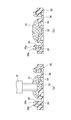
- FIG. 3 is a cross-sectional view of the damper device 10.
- the cross-sectional views of the damper device 10 shown in FIGS. 3 (a) and 3 (b) are both along the axial direction, but the rotation positions are different. Note that FIGS. 2 and 3 show a state in which the viscous liquid is not filled.
- the base 20 has a peripheral wall portion 30, a recess 32, a base inclined surface 34, an annular groove portion 36, an annular recess portion 38, a tooth portion 40, and a connecting hole portion 42.
- the cap 22 has an insertion hole 60, an outer peripheral wall portion 62, a cap inclined surface 64, and an inner peripheral groove portion 66.
- the rotor 24 has a rotating shaft portion 50, an inclined portion 52, a through hole portion 54, an annular wall portion 56, and a convex portion 58.
- the connecting gear 26 has a connecting hole 68.
- the base 20 is formed in a bottomed cylindrical shape.
- a recess 32, a base inclined surface 34, and an annular groove 36 are formed at the bottom of the base 20.
- the recess 32 is formed as a cylindrical recess in the center of the base 20. It becomes easy to put a lot of viscous liquid in the recess 32 during the assembling process.
- the base inclined surface 34 is formed on the inner surface of the base 20, is inclined so as to rise outward in the radial direction from the recess 32, and is inclined with respect to a surface orthogonal to the axial direction. That is, the base inclined surface 34 extends in a direction away from the bottom surface of the base 20 in the radial direction.
- the base inclined surface 34 is formed in a conical shape recessed from the inner edge of the annular groove portion 36 toward the recess 32.
- the annular groove portion 36 is continuously provided on the radial outer side of the base inclined surface 34, and is formed by being recessed in an annular shape.
- the annular groove 36 guides the rotation of the rotor 24.
- the peripheral wall portion 30 is formed so as to be connected to the annular groove portion 36 and to stand on the outer periphery of the base 20.
- a tooth portion 40 is formed on the outer peripheral surface of the peripheral wall portion 30. The tooth portion 40 meshes with a fixed body, for example, to regulate the rotation of the base 20.
- the annular recessed portion 38 is formed by recessing the upper end portion of the peripheral wall portion 30, and is formed in an annular shape along the peripheral wall portion 30. Excess viscous liquid is stored in the annular recess 38.
- the peripheral wall portion 30 has an inner side wall portion 30a and an outer wall portion 30b that sandwich the annular recess portion 38 in the radial direction.
- the inner side wall portion 30a is set so that the height in the axial direction is lower than that of the outer wall portion 30b. This makes it difficult for the viscous liquid to move to the outer diameter side of the outer wall portion 30b.
- the tip end side of the inner side wall portion 30a is inclined in a tapered shape so as to rise outward in the radial direction.
- the connecting hole 42 is formed in an annular shape on the lower surface of the base 20 and engages with a protrusion formed on a pedestal on which the damper device 10 is attached. As a result, the damper device 10 can be stably attached. Further, the connecting hole portion 42 is formed not on the central side but on the outer side in the radial direction from the annular groove portion 36, and is provided at a position where the connecting hole portion 42 overlaps when viewed in the axial direction of the pool chamber 44, so that the axial height of the base 20 is increased. Can be suppressed.
- the rotating shaft portion 50 of the rotor 24 is erected in the center of the rotor 24 and is formed in a columnar shape.
- the rotor 24 rotates about the axis of the rotating shaft portion 50.
- a flat surface that fits into the connecting gear 26 is formed on the side surface of the rotating shaft portion 50 on the tip end side.
- a plurality of inclined portions 52 project outward from the rotating shaft portion 50 in the radial direction and are formed at equal intervals in the circumferential direction.
- a through hole portion 54 is formed between the adjacent inclined portions 52.
- the inclined portion 52 extends so as to rise outward in the radial direction from the rotating shaft portion 50, and is inclined along the base inclined surface 34 as shown in FIG. 3A.
- the inclined portion 52 is inclined with respect to a plane orthogonal to the rotating shaft portion 50, and is inclined outward in the radial direction and upward in the axial direction.
- the inclined portion 52 and the through hole portion 54 have the same radial length.
- the annular wall portion 56 is formed in a cylindrical shape, is located on the radial outer side of the plurality of inclined portions 52, and hangs down from the outer peripheral edge of the inclined portions 52.
- the annular wall portion 56 fits into and engages with the annular groove portion 36 of the base 20 to stabilize the rotation of the rotor 24.
- the convex portion 58 is formed in a columnar shape so as to project the rotating shaft portion 50 downward, and is coaxial with the rotating shaft portion 50.
- An axial groove for securing a gas movement path is formed on the outer peripheral surface of the convex portion 58. The rotation of the rotor 24 can be stabilized by engaging the convex portion 58 in the concave portion 32.
- the cap 22 sandwiches the rotor 24 with the base 20 and defines the storage chamber 70 of the rotor 24 together with the base 20.
- the insertion hole 60 is formed in the center of the cap 22 and exposes the rotating shaft portion 50 of the rotor 24 to the outside from the accommodation chamber 70.
- the rotating shaft portion 50 is inserted into the insertion hole 60.
- the outer peripheral wall portion 62 is formed in a cylindrical shape on the outer periphery of the cap 22.
- the inner peripheral groove portion 66 is formed inside the outer peripheral wall portion 62, receives the peripheral wall portion 30 of the base 20, and is coupled to the peripheral wall portion 30.
- the inner peripheral groove portion 66 faces the annular recessed portion 38 of the base 20.
- the first seal portion 46 and the second seal portion 48 are formed by welding.
- the first seal portion 46 and the second seal portion 48 of FIGS. 3 (a) and 3 (b) are shown in a state in which the base 20 and the cap 22 of the seal portion are overlapped and not melted.
- the first seal portion 46 is formed on the inner peripheral surface of the peripheral wall portion 30, and the second seal portion 48 is formed on the outer peripheral surface of the peripheral wall portion 30.
- the pool chamber 44 is formed on the radial outer side of the storage chamber 70 by being closed by the first seal portion 46 and the second seal portion 48.
- the base 20 and the cap 22 define a viscous liquid pool 44 on the radial outer side of the storage chamber 70.
- the sump chamber 44 is formed by the peripheral wall portion 30 of the base 20 and the inner peripheral groove portion 66 of the cap 22, and the volume of the sump chamber 44 is secured by the annular recessed portion 38.
- the sump chamber 44 is formed along the circumferential direction and stores the viscous liquid discharged from the storage chamber 70.
- the storage chamber 70 is filled with a sufficient viscous liquid, and the storage chamber 44 stores the excess viscous liquid.
- the cap inclined surface 64 is formed on the inner surface of the cap 22, is inclined so as to be lowered inward in the radial direction, and is inclined with respect to a surface orthogonal to the axial direction.
- the cap inclined surface 64 is formed parallel to the inclined portion 52 and the base inclined surface 34.
- the inclined portion 52 of the rotor 24 is sandwiched between the base inclined surface 34 and the cap inclined surface 64.
- the inclined portion 52 is located in the area in the accommodation chamber 70 formed by the base inclined surface 34 and the cap inclined surface 64. That is, the base inclined surface 34 faces the lower surface of the inclined portion 52, the cap inclined surface 64 faces the upper surface of the inclined portion 52, and the base inclined surface 34, the inclined portion 52, and the cap inclined surface 64 overlap when viewed in the axial direction. Is located.
- the accommodation chamber 70 is formed so as to rise outward in the radial direction from the position of the rotating shaft portion 50.
- the seal ring 28 surrounds the rotating shaft portion 50, abuts on the outer peripheral surface of the rotating shaft portion 50 and the inner peripheral surface of the insertion hole 60, and the viscous liquid in the storage chamber 70 leaks through the insertion hole 60. suppress.
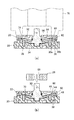
- FIG. 4 is a diagram illustrating an assembly process of the damper device 10.
- the discharge port of the discharge device 72 is aligned with the central position of the base 20, and the discharge device 72 discharges the viscous liquid 74.
- the viscous liquid 74 rests in the center of the base 20 and is discharged in excess of the amount required for the containment chamber 70.
- the recess 32 makes it easier to place more viscous liquid 74 on the base 20.
- FIG. 5 is a diagram showing a continuation of the assembly process of the damper device 10 of FIG.
- the rotor 24 is brought close to the base 20 from above and placed on the base 20 as shown in FIG. 5 (b).
- the convex portion 58 enters the concave portion 32 and pushes the viscous liquid 74, and the viscous liquid 74 protrudes upward from the through hole portion 54 and becomes a raised state.
- the convex portion 58 of the rotor 24 fits into and engages with the concave portion 32 of the base 20. If the concave-convex relationship between the base 20 and the rotor 24 is opposite, gas may accumulate in the concave portion of the rotor 24, but by forming the convex portion 58 in the rotor 24, it is possible to suppress the accumulation of gas. Further, since the base inclined surface 34 is formed so as to rise along the inclined portion 52 of the rotor 24, the gas on the central side can be guided outward in the radial direction.
- FIG. 6 is a diagram showing a continuation of the assembly process of the damper device 10 of FIG.
- the cap 22 is brought closer to the base 20 side from above, and as shown in FIG. 6B, the cap inclined surface 64 comes into contact with the raised viscous liquid 74, and the viscous liquid Push 74 apart.
- the viscous liquid 74 and the gas are guided by the cap inclined surface 64 and the inclined portion 52 and spread in the radial direction, and are guided toward the annular recess portion 38 by the inclination. Since the cap inclined surface 64 and the inclined portion 52 are inclined so as to rise outward in the radial direction, the gas in the accommodation chamber 70 can be easily pushed out in the radial direction.
- FIG. 7 is a diagram showing a continuation of the assembly process of the damper device 10 of FIG.
- the cap 22 is brought close to the base 20, the tip of the outer peripheral wall portion 62 comes into contact with the outer wall portion 30b and the approach stops.
- the viscous liquid 74 is pushed by the cap 22 and spreads to the annular groove portion 36 and the annular recess portion 38.
- the ultrasonic welding device 76 is driven in a state where the tip of the outer peripheral wall portion 62 and the outer wall portion 30b are in contact with each other, the contact portion is melted and can be approached, and the cap 22 is pushed further onto the base 20. As they approach each other, the inner peripheral edge of the inner peripheral groove portion 66 comes into contact with the inner side wall portion 30a. By melting the contact portion between the tip of the outer peripheral wall portion 62 and the outer wall portion 30b, the second seal portion 48 is formed, and the viscous liquid 74 can be prevented from leaking to the outside of the damper device 10.
- the first seal portion 46 is formed. As shown in FIG. 7B, the first seal portion 46 cuts off the communication between the storage chamber 70 and the storage chamber 44. The first sealing portion 46 seals between the accommodating chamber 70 and the collecting chamber 44. As a result, it is possible to limit the return of the gas to the storage chamber 70 after pushing the gas into the storage chamber 44, and prevent the viscous resistance generated when the rotor 24 is rotated due to the accumulation of air bubbles in the storage chamber 70 from being stably exhibited. be able to.
- the sump chamber 44 is closed to the outside by the second seal portion 48 on the radial outer side of the sump chamber 44, and the viscous liquid 74 can be prevented from leaking to the outside.
- FIG. 8 is a partial cross-sectional view of the damper device 10.
- the portion where the first seal portion 46 and the second seal portion 48 are formed is shown in a state where the base 20 and the cap 22 are overlapped with each other, but the overlapped portions are actually melted and joined.
- the second seal portion 48 is melted before the first seal portion 46 and welding is started. Since the second seal portion 48 is formed before the first seal portion 46, the seal allowance L2 of the second seal portion 48 is larger than the seal allowance L1 of the first seal portion 46, and the axial length is long. It is formed.
- the first seal portion 46 and the second seal portion 48 are formed in an annular shape, the axial length of the first seal portion 46 is the seal allowance L1, and the axial length of the second seal portion 48 is the seal allowance L2. is there.
- the cap 22 when the cap 22 is pushed toward the base 20, it is possible to secure a path for pushing gas from the accommodating chamber 70 to the collecting chamber 44 side until the pushing is completed. That is, the gas can be pushed out from the storage chamber 70 while the second seal portion 48 is formed. As a result, the viscous liquid 74 is filled in the storage chamber 70 with a sufficient filling rate. Further, by starting the formation of the second seal portion 48 first, it is possible to prevent the viscous liquid 74 from leaking to the outside in the step of pushing the cap 22.
- the second seal portion 48 is started to be welded while the first seal portion 46 is being welded, and the first seal portion 48 is welded.
- the cap 22 is pushed toward the base 20 while melting both the seal portion 46 and the second seal portion 48.
- the first seal portion 46 and the second seal portion 48 can be formed in one pushing step, and the work efficiency can be improved.
- the axial lengths of the annular wall portion 56 and the annular groove portion 36 are secured in order to generate a desired damping force. There is a need. Since the inclined portion 52 is raised, even if the annular wall portion 56 is hung down from the inclined portion 52, it is possible to suppress an increase in the axial length of the entire damper device 10. Further, since the pool chamber 44 is provided at a position where it does not overlap the annular wall portion 56 when viewed in the axial direction, the axial length of the damper device 10 becomes longer while ensuring the axial length of the annular wall portion 56. It can be suppressed.
- the base inclined surface 34 extends to the annular groove portion 36, and all of the portions facing the inclined portion 52 and the through hole portion 54 are formed so as to be inclined.
- FIG. 9 is an exploded view of the damper device of the first modified example.
- the damper device 100 of the first modification is mainly different from the damper device 10 shown in FIG. 2 in that the cap is divided into two members.
- the damper device 100 includes members of a base 120, a first cap 122a, a second cap 122b, a seal ring 28, and a rotor 124.
- the rotor 124, the seal ring 28, the first cap 122a, and the second cap 122b with the base 120 at the bottom are attached in this order from above.
- the configuration of each member will be described with reference to the new drawings.
- FIG. 10 is a perspective sectional view of the damper device 100 of the first modification. Further, FIG. 11 is a partially enlarged view of the damper device 100 shown in FIG.
- the damper device 100 further includes a first seal portion 93, a second seal portion 94, a third seal portion 95, and a fourth seal portion 96 that connect the members.
- the base 120 has a bottom portion 80, an inner side wall portion 82a and an outer wall portion 82b.
- the bottom 80 of the base 120 is also the bottom of the damper device 100 and constitutes the bottom of the storage chamber 170.
- the inner side wall portion 82a and the outer wall portion 82b stand upright from the bottom portion 80 and face each other.
- the inner side wall portion 82a is located inside the outer wall portion 82b.
- the storage chamber 170 is located inside the inner side wall portion 82a, and the pool portion 144 is located between the inner side wall portion 82a and the outer wall portion 82b.
- the rotor 124 has a rotating shaft portion 150 and an overhanging portion 152.
- the rotating shaft portion 150 is erected in the center of the rotor 124 and is formed in a columnar shape.
- the overhanging portion 152 projects radially outward from the rotating shaft portion 150 and is accommodated in the accommodating chamber 170.
- the first cap 122a defines the base 120 and the storage chamber 170.
- the storage chamber 170 is filled with the viscous liquid 74.
- the second cap 122b is fixed to the base 120 to prevent the first cap 122a from coming off.
- the second cap 122b can prevent the first cap 122a from coming off while maintaining the closed state of the storage chamber 170.
- the amount of air remaining in the accommodation chamber 170 can be reduced.
- the first cap 122a has a first annular plate portion 84, a first peripheral wall portion 86, and an engaging portion 88.
- the first annular plate portion 84 has an insertion hole 60 in the center and extends radially outward from the insertion hole 60.
- the first annular plate portion 84 has an annular rib 84a formed so as to project from the upper surface.
- the first peripheral wall portion 86 projects so as to hang down from the outer peripheral edge of the first annular plate portion 84, and is formed in a substantially cylindrical shape.
- the engaging portion 88 is formed at the tip end portion of the first peripheral wall portion 86, and engages with the inner side wall portion 82a of the base 120 so as to face in the axial direction.
- the engaging portion 88 is located between the accommodating chamber 170 and the reservoir chamber 144. As a result, the storage chamber 170 defined by the base 120 and the first cap 122a is closed.
- the engaging portion 88 is formed in a convex shape protruding downward, and the tip portion of the inner side wall portion 82a is formed in a concave shape. As a result, the engaging portion 88 and the tip end portion of the inner side wall portion 82a can be concavely engaged with each other, and the base 120 and the first cap 122a can be prevented from being displaced in the radial direction.
- the second cap 122b has a second annular plate portion 90 and a second peripheral wall portion 92.
- the second annular plate portion 90 has a central hole 90a and extends radially outward from the central hole 90a.
- the second peripheral wall portion 92 projects so as to hang down from the lower surface of the second annular plate portion 90, and is formed in a substantially cylindrical shape.
- the second peripheral wall portion 92 is located in the middle in the radial range of the second annular plate portion 90. That is, the second annular plate portion 90 projects radially outward from the second peripheral wall portion 92.
- the annular rib 84a enters the inside of the central hole 90a, and the inner peripheral region of the second annular plate portion 90 overlaps with the outer peripheral region of the first annular plate portion 84 in the axial direction.
- the second peripheral wall portion 92 is inserted between the inner side wall portion 82a and the outer wall portion 82b, and is located on the radial outer side of the first peripheral wall portion 86.
- the second peripheral wall portion 92 of the second cap 122b has a plurality of ribs 92a on the outer peripheral surface.
- the plurality of ribs 92a are formed so as to project from the outer peripheral surface of the second peripheral wall portion 92, and are formed apart from each other in the circumferential direction.
- the rib 92a is provided in a shape along the inner peripheral surface of the outer wall portion 82b.
- the first seal portion 93, the second seal portion 94, the third seal portion 95, and the fourth seal portion 96 shown in FIG. 11 are formed by welding.
- the seal portion of each member is shown in a state where it is not melted by welding.
- the first seal portion 93 is formed by welding the outer peripheral surface of the first peripheral wall portion 86 of the first cap 122a and the inner peripheral surface of the second peripheral wall portion 92 of the second cap 122b.
- the first seal portion 93 is located between the accommodating chamber 170 and the reservoir portion 144 in the radial direction, and fixes the first cap 122a and the second cap 122b.
- the first seal portion 93 blocks communication between the storage chamber 170 and the outside, and prevents the viscous liquid 74 from leaking from the inside of the storage chamber 170.
- the second seal portion 94 is formed by welding the outer peripheral surface of the inner side wall portion 82a of the base 120 and the inner peripheral surface of the second peripheral wall portion 92 of the second cap 122b.
- the second seal portion 94 is located between the storage chamber 170 and the pool portion 144 in the radial direction, blocks communication between the storage chamber 170 and the pool portion 144, and prevents the viscous liquid 74 from leaking from the storage chamber 170.
- the second cap 122b is fixed to the base 120 by the first seal portion 93 and the second seal portion 94 to seal between the storage chamber 170 and the storage chamber 144, and is fixed to the first cap 122a (welding in the embodiment). Is).
- the first cap 122a has a function of closing the storage chamber 170
- the second cap 122b has a function of fixing to the base 120.
- the first seal portion 93 and the second seal portion 94 are connected to the engaging portion 88 and are formed continuously in the axial direction on the radial outer side of the engaging portion 88. That is, the space between the engaging portion 88 and the inner side wall portion 82a is sealed up and down, and the viscous liquid 74 is restricted from moving from between the engaging portion 88 and the inner side wall portion 82a in the radial direction. Further, the second cap 122b is bonded to the first cap 122a and the base 120 by welding. By sealing the positions of the first seal portion 93 and the second seal portion 94 close to the storage chamber 170, it is possible to prevent the viscous liquid 74 injected in advance from being scattered in various places and stabilize the amount of seal in the storage chamber 170. it can.
- the third seal portion 95 is formed by welding the outer peripheral surface of the second peripheral wall portion 92 and the inner peripheral surface of the outer wall portion 82b.
- the third seal portion 95 is located outside the pool portion 144 and seals the viscous liquid 74 from leaking from the pool portion 144. Further, the third seal portion 95 connects the second cap 122b and the base 120.
- the fourth seal portion 96 is formed by welding the outer peripheral surface of the first annular plate portion 84 and the inner peripheral surface of the second peripheral wall portion 92.
- the fourth seal portion 96 seals the viscous liquid 74 from leaking from the gap between the first cap 122a and the second cap 122b. Further, the fourth seal portion 96 connects the first cap 122a and the second cap 122b.
- the first seal portion 93 and the fourth seal portion 96 can doubly seal the viscous liquid 74 from leaking between the first cap 122a and the second cap 122b. Further, the second seal portion 94 and the third seal portion 95 can doubly seal the viscous liquid 74 from leaking between the second cap 122b and the base 120.
- FIG. 12 is a diagram for explaining an assembly process of the damper device 100 of the first modification.
- the viscous liquid 74 is placed in the center of the base 120, the rotor 124 is placed on the base 120, and the first cap 122a is pressed from above toward the base 120. As a result, the viscous liquid 74 is pushed out to the pool portion 144 side through the gap between the engaging portion 88 and the inner side wall portion 82a.
- the first cap 122a approaches the base 120, and as shown in FIG. 12A, the engaging portion 88 of the first cap 122a is in a state of being engaged with the tip end portion of the inner side wall portion 82a of the base 120. ..
- the engagement between the engaging portion 88 and the inner side wall portion 82a closes the storage chamber 170 and restricts the movement of the viscous liquid 74.
- the step of welding the second cap 122b is executed with the storage chamber 170 closed. As a result, it is possible to prevent the viscous liquid 74 from being compressed in the storage chamber 170 by pushing the second cap 122b.
- the second cap 122b is brought closer to the base 120 with the second peripheral wall portion 92 aligned between the inner side wall portion 82a and the outer wall portion 82b.
- the tip of the second peripheral wall portion 92 corresponds to the inclined surface 97 formed on the outer peripheral surface of the first annular plate portion 84.
- the inclined surface 97 is inclined so as to project downward in the radial direction, and projects outward in the radial direction from the inner peripheral surface of the second peripheral wall portion 92. That is, when the second peripheral wall portion 92 is pushed into the outer periphery of the first annular plate portion 84, it always comes into contact with the inclined surface 97.
- the ultrasonic welding device 76 With the second peripheral wall portion 92 in contact with the inclined surface 97 of the first annular plate portion 84, the ultrasonic welding device 76 is driven to melt the contact portion, and the second cap 122b further approaches the base 120.
- FIG. 12B shows a state in which the second cap 122b is pushed toward the base 120 and the inner peripheral surface of the second peripheral wall portion 92 and the outer peripheral surface of the first peripheral wall portion 86 are melted, and the first seal portion is shown. 93 is starting to be generated. Further, the second peripheral wall portion 92 hits the engaging portion between the engaging portion 88 and the inner side wall portion 82a and begins to melt, and the accommodation chamber 170 is sealed. By melting the engaging portion between the engaging portion 88 and the inner side wall portion 82a, the communication between the accommodating chamber 170 and the collecting portion 144 can be reliably cut off.
- the inner peripheral surface of the second peripheral wall portion 92 on the base end side corresponds to the outer peripheral edge of the first annular plate portion 84, and the outer peripheral surface of the second peripheral wall portion 92 on the base end side is the outer wall portion 82b. It corresponds to the inner peripheral edge on the tip side.
- the hit portion begins to be melted by the ultrasonic welding device 76.
- FIG. 12C the pushing of the second cap 122b is completed, the first seal portion 93, the second seal portion 94, the third seal portion 95, and the fourth seal portion 96 are formed, and the assembly of the damper device 100 is completed.
- the first seal portion 93 is formed, then the second seal portion 94 is formed, and then the third seal portion 95 and the fourth seal portion 96 are formed.
- the accommodating chamber 170 can be sealed, and then the pool portion 144 can be sealed.
- the welding start timings of the second seal portion 94, the third seal portion 95, and the fourth seal portion 96 may be at the same time.
- FIG. 13 is a perspective sectional view of the damper device 200 of the second modified example.
- FIG. 14 is a partially enlarged view of the damper device 200 shown in FIG.
- the positions of the first seal portion 293 and the second seal portion 294 are different from those of the damper device 100 of the first modification shown in FIG. 10, and the positions of the first seal portion 293 and the second seal portion 293 and the second are different.
- the seal portion 294 is located above the first seal portion 93 and the second seal portion 94 of the damper device 100.
- the damper device 200 includes a base 220, a first cap 222a, a second cap 222b, a rotor 124, a first seal portion 293, a second seal portion 294, and a third seal portion 295.
- the base 220 has a bottom 80, an inner wall 282a and an outer wall 282b.
- the inner side wall portion 282a and the outer wall portion 282b are erected from the bottom portion 80 and face each other.
- the inner side wall portion 282a is located inside the outer wall portion 282b.
- the accommodation chamber 170 is located inside the inner side wall portion 282a, and the pool portion 244 is located between the inner side wall portion 282a and the outer wall portion 282b.
- the inner side wall portion 282a is erected so as to cover the outer periphery of the accommodation chamber 170, and is erected above the overhanging portion 152. By forming the inner side wall portion 282a high, the pool chamber 244 can be enlarged.
- the first cap 222a is formed in a substantially disk shape and has an insertion hole 60 in the center.
- the engaging portion 288 of the first cap 222a is formed on the lower surface on the outer peripheral side and engages with the inner side wall portion 282a of the base 220 so as to face in the axial direction.
- the second cap 222b has a second annular plate portion 290 and a peripheral wall portion 292.
- the second annular plate portion 290 extends outward in the radial direction.
- the peripheral wall portion 292 projects so as to hang down from the lower surface of the second annular plate portion 290, and is formed in a substantially cylindrical shape.
- FIG. 15 is a diagram for explaining an assembly process of the damper device 200 of the second modification.
- the engaging portion 288 of the first cap 222a is engaged with the tip end portion of the inner side wall portion 282a of the base 220, and the storage chamber 170 is closed.
- the step of welding the second cap 222b is executed. As a result, it is possible to prevent the viscous liquid 74 from being compressed in the storage chamber 170 by pushing the second cap 222b.
- the second cap 222b is brought closer toward the base 220 with the peripheral wall portion 292 aligned between the inner side wall portion 282a and the outer wall portion 282b.
- the tip of the peripheral wall portion 292 corresponds to an inclined surface 297 formed on the outer peripheral surface of the first cap 222a.
- the contacted portion is melted by the ultrasonic welding device 76.
- FIG. 15B shows a state in which the second cap 222b is pushed toward the base 220 and the inner peripheral surface of the peripheral wall portion 292 and the outer peripheral surface of the first cap 222a are melted, and the first seal portion 293 is generated. I'm starting. Further, the peripheral wall portion 292 hits the engaging portion of the engaging portion 288 and the inner side wall portion 282a and begins to melt, and the accommodation chamber 170 is sealed.
- the outer peripheral surface of the peripheral wall portion 292 on the base end side corresponds to the inner peripheral edge of the outer wall portion 282b on the distal end side.
- the pushing of the second cap 222b is completed, the first seal portion 293, the second seal portion 294, and the third seal portion 295 are formed, and the assembly of the damper device 200 is completed.
- the accommodation chamber 170 can be sealed, and then the reservoir portion 244 can be sealed.
- a mode in which the fixed body or the opening / closing body is connected to the tooth portion 40 formed on the base 20 is shown, but the present invention is not limited to this mode.
- a flange plate-shaped mounting portion having a screw hole may be formed.
- the connecting gear 26 is connected to the opening / closing body, the base 20 is connected to the fixed body in a state where rotation is restricted.
- the mode in which the first seal portion 46 and the second seal portion 48 are formed by welding is shown, but the present invention is not limited to this mode.
- the second seal portion 48 may be formed by adhesion or mechanical coupling
- the first seal portion 46 may be formed by mechanical coupling, for example, a seal ring.
- the method is not limited to ultrasonic welding, and may be formed by another method such as vibration welding or laser welding.
- the first seal portion 93, the second seal portion 94, the third seal portion 95, and the fourth seal portion 96 are also limited to the mode formed by welding like the first seal portion 46 and the second seal portion 48. It does not have to be, and may be formed by adhesion or mechanical bonding. In any case, these sealing portions fix the members to each other and restrict the movement of the viscous liquid 74. That is, fixation includes welding, adhesion, and the like.
- the base inclined surface 34 and the cap inclined surface 64 are parallel to the inclined portion 52 of the rotor 24
- the present invention is not limited to this aspect and may not be parallel.
- the base inclined surface 34, the cap inclined surface 64, and the inclined portion 52 are inclined so as to rise outward in the radial direction, and are inclined with respect to the plane orthogonal to the rotation shaft portion 50, and the viscous liquid 74. Is guided to the pool room 44.
- the present invention relates to a damper device filled with a viscous liquid.
- damper device 20 base, 22 cap, 24 rotor, 26 connecting gear, 28 seal ring, 30 peripheral wall part, 30a inner side wall part, 30b outer wall part, 32 recesses, 34 base inclined surface, 36 annular groove, 38 annular recess Part, 40 tooth part, 42 connecting hole part, 44 pool chamber, 46 first seal part, 48 second seal part, 50 rotating shaft part, 52 inclined part, 54 through hole part, 56 annular wall part, 58 convex part, 60 insertion hole, 62 outer peripheral wall part, 64 cap inclined surface, 66 inner peripheral groove part, 68 connecting hole, 70 accommodation chamber, 72 discharge device, 74 viscous liquid, 76 ultrasonic welding device, 88 engaging part, 93 first seal Part, 94 2nd seal part, 122a 1st cap, 122b 2nd cap.
Landscapes
- Engineering & Computer Science (AREA)
- General Engineering & Computer Science (AREA)
- Mechanical Engineering (AREA)
- Fluid-Damping Devices (AREA)
Abstract
ダンパー装置10は、ベース20と、ベース20に回転可能に支持されるロータ24と、ベース20とともにロータ24の収容室を画成するキャップ22と、収容室に充填される粘性液体と、を備える。ベース20およびキャップ22は、収容室の径方向外側に粘性液体の溜まり室を画成し、収容室と溜まり室の間をシールする。溜まり室は、溜まり室の径方向外側におけるベースおよびキャップのシールによって閉塞される。
Description
本発明は、粘性液体を充填されたダンパー装置に関する。
特許文献1には、回転可能なロータと、ロータを収容するハウジングおよびキャップと、ロータの回転領域に充填される減衰媒体と、ロータの回転領域の外側に設けられ、回転領域に連通する封入部を備えるダンパーが開示されている。ハウジングおよびキャップは複数の環状突部を有し、ロータは上下に突出する円環状のロータ突部を複数有する。ハウジングおよびキャップの環状突部の間隙にロータ突部が嵌合する。
特許文献1に開示される技術では、封入部に存在する気体が環状突部の周りの隙間に移動して、減衰力を低下させるおそれがある。
本発明の目的は、減衰力を安定して発生できるダンパー装置を提供することにある。
上記課題を解決するために、本発明のある態様のダンパー装置は、ベースと、ベースに回転可能に支持されるロータと、ベースとともにロータの収容室を画成するキャップと、収容室に充填される粘性液体と、を備える。ベースおよびキャップは、収容室の径方向外側に粘性液体の溜まり室を画成し、収容室と溜まり室の間をシールする。
本発明によれば、減衰力を安定して発生できるダンパー装置を提供できる。
図1は、実施例のダンパー装置10の斜視図である。ダンパー装置10は、たとえば車両のグローブボックスに取り付けられ、グローブボックスの開閉体(ふた部材)の開閉動作に減衰力を付与する。また、ダンパー装置10は、車両のコンソールボックスに取り付けられ、コンソールボックスの開閉体の開閉に減衰力を付与してもよい。いずれにしてもダンパー装置10は固定体と固定体の開口を開閉する開閉体とに取り付けられる。
ダンパー装置10は、ベース20、キャップ22、ロータ24、連結ギヤ26、シールリング(不図示)および粘性液体(不図示)を備える。粘性液体は、ベース20およびキャップ22の間に充填され、ロータ24の回転に粘性抵抗を付与する。粘性液体は、例えばグリースなどのオイル等であって、ベース20およびキャップ22の間から漏れないように充填される。
ベース20は、固定体および開閉体のいずれか一方に連結し、連結ギヤ26は、固定体および開閉体のいずれか他方に連結する。例えば、連結ギヤ26はラックギヤ等を介して開閉体に連結され、開閉体の動きに応じて回転し、ベース20は固定体に連結される。ロータ24は、連結ギヤ26とともに回転して粘性液体から抵抗力を受け、減衰力を発生する。なお、ダンパー装置10の使用態様は、図1に示すようにベース20を下側に配置し、連結ギヤ26を上側に配置される態様に限定されず、ロータ24の回転軸を鉛直方向に対して傾斜させた状態で使用してもよい。
図2は、ダンパー装置10の分解図である。また、図3は、ダンパー装置10の断面図である。図3(a)および図3(b)に示すダンパー装置10の断面図はともに軸方向に沿ったものであるが回転位置が異なる。なお、図2および図3には、粘性液体が充填されていない状態を示す。
ベース20は、周壁部30、凹部32、ベース傾斜面34、環状溝部36、環状窪み部38、歯部40および連結孔部42を有する。キャップ22は、挿通孔60、外周壁部62、キャップ傾斜面64および内周溝部66を有する。ロータ24は、回転軸部50、傾斜部52、貫通孔部54、環状壁部56および凸部58を有する。連結ギヤ26は、連結孔68を有する。
ベース20は、有底円筒状に形成される。ベース20の底部には、凹部32、ベース傾斜面34および環状溝部36が形成される。凹部32は、ベース20の中央で円筒状に凹んで形成される。組み立て工程時に凹部32に多くの粘性液体を載せやすくなる。
ベース傾斜面34は、ベース20の内面に形成され、凹部32から径方向外向きに立ち上がるように傾斜し、軸方向に直交する面に対して傾斜する。すなわち、ベース傾斜面34は、ベース20の底面に対して径方向外向きに離れる方向に延在する。ベース傾斜面34は、環状溝部36の内縁から凹部32に向かって窪んだ錐状に形成される。
環状溝部36は、ベース傾斜面34の径方向外側に連設し、環状に凹んで形成される。環状溝部36は、ロータ24の回転をガイドする。周壁部30は、環状溝部36に連設し、ベース20の外周に立設するように形成される。周壁部30の外周面には、歯部40が形成される。歯部40は、例えば固定体に噛合してベース20の回転を規制する。
環状窪み部38は、周壁部30を上端部を窪ませて形成され、周壁部30に沿って環状に形成される。環状窪み部38には、余った粘性液体が収容される。周壁部30は、環状窪み部38を径方向に挟む内側壁部30aおよび外側壁部30bを有する。内側壁部30aは、外側壁部30bより軸方向高さが低くなるように設定される。これにより、粘性液体が外側壁部30bより外径側に移動しづらくなる。内側壁部30aの先端側は、径方向外向きに立ち上がるようにテーパ状に傾斜する。
連結孔部42は、ベース20の下面に環状に形成され、ダンパー装置10を取り付ける台座に形成された突起に係合する。これにより、ダンパー装置10を安定して取り付けることができる。また、連結孔部42を中央側ではなく、環状溝部36より径方向外側に形成し、溜まり室44の軸方向に見て重なる位置に設けることで、ベース20の軸方向高さが高くなることを抑えることができる。
ロータ24の回転軸部50は、ロータ24の中央に立設し、柱状に形成される。ロータ24は、回転軸部50の軸周りに回転する。回転軸部50の先端側の側面には、連結ギヤ26に嵌合する平面が形成される。傾斜部52は、回転軸部50から径方向外向き張り出し、周方向に等間隔に離れて複数形成される。図2に示すように、隣り合う傾斜部52の間には貫通孔部54が形成される。傾斜部52は、回転軸部50から径方向外向きに立ち上がるように延在し、図3(a)に示すようにベース傾斜面34に沿って傾斜する。傾斜部52は、回転軸部50に直交する面に対して傾斜し、径方向外向きかつ軸方向上向きに傾斜する。傾斜部52および貫通孔部54の径方向長さは同じである。
環状壁部56は、円筒形状に形成され、複数の傾斜部52の径方向外側に位置し、傾斜部52の外周縁から垂下する。環状壁部56は、ベース20の環状溝部36に収まって係合し、ロータ24の回転を安定させる。
凸部58は、回転軸部50を下方に突出させるように円柱状に形成され、回転軸部50と同軸である。凸部58の外周面には、気体の移動経路を確保するための軸方向溝が形成される。凸部58が凹部32に収まって係合することで、ロータ24の回転を安定させることができる。
キャップ22は、ロータ24をベース20と挟んで、ベース20とともにロータ24の収容室70を画成する。挿通孔60は、キャップ22の中央に形成され、ロータ24の回転軸部50を収容室70から外部に露出させる。挿通孔60には、回転軸部50が挿通される。外周壁部62は、キャップ22の外周に円筒状に形成される。
内周溝部66は、外周壁部62の内側に形成され、ベース20の周壁部30を受け入れて周壁部30に結合する。内周溝部66は、ベース20の環状窪み部38に対向する。結合方法については後述するが、溶着により第1シール部46および第2シール部48が形成される。図3(a)および図3(b)の第1シール部46および第2シール部48は、シール部分のベース20およびキャップ22が重なった状態で溶けていない状態で示される。
第1シール部46は、周壁部30の内周面に形成され、第2シール部48は、周壁部30の外周面に形成される。第1シール部46および第2シール部48により閉塞されて溜まり室44が収容室70の径方向外側に形成される。ベース20およびキャップ22は、収容室70の径方向外側に粘性液体の溜まり室44を画成する。溜まり室44は、ベース20の周壁部30およびキャップ22の内周溝部66とにより形成され、環状窪み部38により溜まり室44の体積が確保されている。溜まり室44は、周方向に沿って形成され、収容室70から出た粘性液体を収容する。収容室70側に十分な粘性液体を満たし、余った粘性液体を溜まり室44が収容する。
キャップ傾斜面64は、キャップ22の内面に形成され、径方向内向きに下がるように傾斜し、軸方向に直交する面に対して傾斜する。キャップ傾斜面64は、傾斜部52およびベース傾斜面34に沿って平行に形成される。ベース傾斜面34およびキャップ傾斜面64によりロータ24の傾斜部52が挟まれている。ベース傾斜面34およびキャップ傾斜面64によって形成される収容室70内の領域に傾斜部52が位置する。つまり、ベース傾斜面34は傾斜部52の下面に対向し、キャップ傾斜面64は傾斜部52の上面に対向し、軸方向に見てベース傾斜面34、傾斜部52およびキャップ傾斜面64が重なって位置する。これにより、収容室70が回転軸部50の位置から径方向外向きに立ち上がるように形成される。
シールリング28は、回転軸部50に環囲し、回転軸部50の外周面および挿通孔60の内周面に当接し、挿通孔60を介して収容室70にある粘性液体が漏れることを抑える。
図4は、ダンパー装置10の組み立て工程について説明する図である。図4(a)に示すように、吐出装置72の吐出口がベース20の中央の位置に合わされ、吐出装置72が粘性液体74を吐出する。図4(b)に示すように、粘性液体74は、ベース20の中央に載っており、収容室70に必要な量より多く吐出される。凹部32により多くの粘性液体74をベース20に載せやすい。
図5は、図4のダンパー装置10の組み立て工程の続きを示す図である。図5(a)に示すように、ロータ24が上方からベース20に接近させられて、図5(b)に示すようにベース20に載置される。ロータ24がベース20に接近すると、凹部32に凸部58が入り込んで粘性液体74を押し、粘性液体74が貫通孔部54から上に出て隆起した状態になる。
ロータ24の凸部58は、ベース20の凹部32に収まって係合する。ベース20およびロータ24の凹凸関係が逆である場合、ロータ24の凹部に気体が溜まるおそれがあるが、ロータ24に凸部58を形成することで、気体が溜まることを抑えることができる。また、ベース傾斜面34がロータ24の傾斜部52に沿って立ち上がるように形成されることで、中央側にある気体を径方向外側に誘導できる。
図6は、図5のダンパー装置10の組み立て工程の続きを示す図である。図6(a)に示すように、キャップ22が上方からベース20側に接近させられて、図6(b)に示すように、キャップ傾斜面64が隆起した粘性液体74に接触し、粘性液体74を押し広げる。粘性液体74および気体は、キャップ傾斜面64や傾斜部52に誘導されて径方向に拡がり、傾斜によって環状窪み部38に向かって誘導される。キャップ傾斜面64および傾斜部52が径方向外向きに立ち上がるように傾斜していることで、収容室70内にある気体を径方向外向きに押し出しやすくなる。
図7は、図6のダンパー装置10の組み立て工程の続きを示す図である。図7(a)に示すように、キャップ22がベース20に向かって接近させられると、外周壁部62の先端が外側壁部30bに当接して接近が止まる。このとき粘性液体74は、キャップ22に押されて環状溝部36や環状窪み部38に拡がっている。
外周壁部62の先端と外側壁部30bが当接した状態で超音波溶着装置76が駆動して、その当接部分が溶かされて接近が可能となり、キャップ22が押されてベース20にさらに接近し、内周溝部66の内周縁が内側壁部30aに当接する。外周壁部62の先端と外側壁部30bの当接部分が溶かされることで、第2シール部48が形成され、粘性液体74がダンパー装置10の外部に漏れることを抑えることができる。
外周壁部62の先端と外側壁部30bの当接部分が溶かされている途中で、内周溝部66の内周縁と内側壁部30aとの当接部分が超音波溶着装置76により溶かされ始め、第1シール部46が形成される。図7(b)に示すように、第1シール部46により収容室70と溜まり室44の連通が遮断される。第1シール部46は、収容室70と溜まり室44の間をシールする。これにより、気体を溜まり室44に押し出した後、気体が収容室70に戻ることを制限でき、収容室70に気泡が溜まってロータ24回転時に発生する粘性抵抗が安定して発揮できないことを抑えることができる。溜まり室44は、溜まり室44の径方向外側における第2シール部48によって外部と閉塞され、粘性液体74が外部に漏れることを抑えられる。
図7(b)に示すように、ベース20およびキャップ22が固定された後、連結ギヤ26が回転軸部50に装着されて、ダンパー装置10の組み立て工程が完了する。
図8は、ダンパー装置10の部分断面図である。図8では、第1シール部46および第2シール部48が形成される部分を、ベース20およびキャップ22が重なった状態で示すが、実際には重なった部分は溶けて結合している。
組み立て工程で説明したように、第2シール部48は、第1シール部46より先に溶かされて溶着開始される。第1シール部46より先に第2シール部48を形成するため、第2シール部48のシール代L2は、第1シール部46のシール代L1より大きく、軸方向長さが長くなるように形成される。第1シール部46および第2シール部48は円環状に形成され、第1シール部46の軸方向長さがシール代L1であり、第2シール部48の軸方向長さがシール代L2である。
これにより、キャップ22をベース20側に押し込む際に、収容室70から溜まり室44側へ気体を押し出す経路を押し込み完了まで確保できる。つまり、第2シール部48を形成している間も収容室70から気体を押し出すことができる。これにより粘性液体74は、十分な充填率で収容室70に充填される。また、第2シール部48を先に形成開始することで、キャップ22を押し込む工程で粘性液体74が外部に漏れることを抑えることができる。
また、第1シール部46のシール代L1が第2シール部48のシール代L2より長いため、第1シール部46を溶着している途中から第2シール部48を溶着開始して、第1シール部46および第2シール部48の両方を溶かしつつ、キャップ22をベース20側に押し込める。これにより、一回の押し込み工程で第1シール部46および第2シール部48を形成でき、作業効率を高めることができる。
ロータ24の回転時に発生する粘性抵抗は主に環状壁部56の領域で発生するため、所望の減衰力を発生させるためには、環状壁部56および環状溝部36の軸方向長さを確保する必要がある。傾斜部52が立ち上がっているため、傾斜部52から環状壁部56を垂下させても、ダンパー装置10全体の軸方向長さが長くなることを抑えることができる。また、溜まり室44が軸方向に見て環状壁部56に重ならない位置に設けられることで、環状壁部56の軸方向長さを確保しつつ、ダンパー装置10の軸方向長さが長くなることを抑えることができる。
径方向に見て溜まり室44が収容室70に重なる位置に設けられることで、ダンパー装置10の軸方向高さを抑えることができる。ベース傾斜面34は、環状溝部36に至るまで延在し、傾斜部52および貫通孔部54に対向部分の全てが傾斜して形成される。
図9は、第1変型例のダンパー装置の分解図である。第1変形例のダンパー装置100は、図2に示すダンパー装置10と比べて、キャップが2部材に分かれているいる点が主に異なる。
ダンパー装置100は、ベース120、第1キャップ122a、第2キャップ122b、シールリング28およびロータ124の部材を含んで構成される。ベース120を底ににした、ロータ124、シールリング28、第1キャップ122a、第2キャップ122bが上方から順に取り付けられる。各部材の構成を新たな図面を参照しつつ説明する。
図10は、第1変形例のダンパー装置100の斜視断面図である。また、図11は、図10に示すダンパー装置100の部分拡大図である。ダンパー装置100は、各部材を結合する第1シール部93、第2シール部94、第3シール部95および第4シール部96をさらに備える。ベース120は、底部80、内側壁部82aおよび外側壁部82bを有する。
ベース120の底部80は、ダンパー装置100の底部でもあり、収容室170の底面を構成する。内側壁部82aおよび外側壁部82bは、底部80から立設し、互いに対向する。内側壁部82aは、外側壁部82bの内側に位置する。内側壁部82aの内側に収容室170が位置し、内側壁部82aおよび外側壁部82bの間に溜まり部144が位置する。
ロータ124は、回転軸部150および張出部152を有する。回転軸部150は、ロータ124の中央に立設し、柱状に形成される。張出部152は、回転軸部150から径方向外向き張り出し、収容室170に収容される。
第1キャップ122aは、ベース120と収容室170を画成する。収容室170には、粘性液体74が充填される。第2キャップ122bは、ベース120に固定され、第1キャップ122aが外れることを止める。これにより、第1キャップ122aが収容室170を閉塞した後、収容室170を閉塞した状態を維持しつつ、第2キャップ122bが第1キャップ122aを外れ止めできる。これにより、収容室170に残留する空気量を低減できる。
第1キャップ122aは、第1環状板部84、第1周壁部86および係合部88を有する。第1環状板部84は、中央に挿通孔60を有し、挿通孔60から径方向外向きに延在する。第1環状板部84は、上面に突出して形成される環状リブ84aを有する。第1周壁部86は、第1環状板部84の外周縁から垂下するように突出し、略円筒状に形成される。
係合部88は、第1周壁部86の先端部に形成され、ベース120の内側壁部82aと軸方向に向かい合って係合する。係合部88は、収容室170および溜まり室144の間に位置する。これにより、ベース120と第1キャップ122aにより画成される収容室170が閉じられる。
係合部88は下方に突出した凸形状に形成され、内側壁部82aの先端部は凹形状に形成される。これにより、係合部88と内側壁部82aの先端部とが凹凸係合することができ、ベース120と第1キャップ122aが径方向にずれることを抑えることができる。
第2キャップ122bは、第2環状板部90および第2周壁部92を有する。第2環状板部90は、中央孔90aを有し、中央孔90aから径方向外向きに延在する。第2周壁部92は、第2環状板部90の下面から垂下するように突出し、略円筒状に形成される。第2周壁部92は、第2環状板部90の径方向の範囲において中途に位置する。つまり、第2環状板部90は、第2周壁部92より径方向外向きに張り出している。
中央孔90aの内側に環状リブ84aが入り込み、第2環状板部90の内周領域は、第1環状板部84の外周領域と軸方向に重なる。第2周壁部92は、内側壁部82aおよび外側壁部82bの間に差し込まれ、第1周壁部86の径方向外側に位置する。
第2キャップ122bの第2周壁部92は、外周面に複数のリブ92aを有する。複数のリブ92aは、第2周壁部92の外周面に突出して形成され、周方向に離れて形成される。リブ92aは、外側壁部82bの内周面に沿った形状に設けられる。第2周壁部92が内側壁部82aおよび外側壁部82bの間に押し込まれるときに、複数のリブ92aが外側壁部82bに当接することで、第2キャップ122bの押し込み姿勢が安定する。
図11に示す第1シール部93、第2シール部94、第3シール部95および第4シール部96は、溶着により形成される。図10および図11では、各部材のシール部分が溶着で溶けていない状態で示されている。
第1シール部93は、第1キャップ122aの第1周壁部86の外周面と、第2キャップ122bの第2周壁部92の内周面との溶着により形成される。第1シール部93は、径方向において収容室170と溜まり部144の間に位置し、第1キャップ122aおよび第2キャップ122bを固着させる。第1シール部93は、収容室170と外部との連通を遮断し、粘性液体74が収容室170内から漏れることを封じる。
第2シール部94は、ベース120の内側壁部82aの外周面と、第2キャップ122bの第2周壁部92の内周面との溶着により形成される。第2シール部94は、径方向において収容室170と溜まり部144の間に位置し、収容室170と溜まり部144の連通を遮断し、粘性液体74が収容室170から漏れることを封じる。
第2キャップ122bは、第1シール部93および第2シール部94により、ベース120に固着して収容室170および溜まり室144の間をシールするとともに、第1キャップ122aに固着(実施例では溶着である)する。これにより、第1キャップ122aが収容室170を閉塞する機能を有し、第2キャップ122bがベース120に固定する機能を有する。
第1シール部93および第2シール部94は、係合部88に連なり、係合部88の径方向外側で軸方向に連続して形成される。つまり、係合部88と内側壁部82aの間が上下にシールされ、粘性液体74が係合部88と内側壁部82aの間から径方向外側に移動することが規制される。また、第2キャップ122bが溶着により第1キャップ122aおよびベース120に結合する。第1シール部93および第2シール部94が収容室170に近い位置をシールすることで、予め注入した粘性液体74が各所に散らばることを抑え、収容室170内のシール量を安定させることができる。
第3シール部95は、第2周壁部92の外周面と外側壁部82bの内周面との溶着により形成される。第3シール部95は、溜まり部144の外側に位置し、粘性液体74が溜まり部144から漏れることを封じる。また、第3シール部95は、第2キャップ122bおよびベース120を結合する。
第4シール部96は、第1環状板部84の外周面と、第2周壁部92の内周面との溶着により形成される。第4シール部96は、第1キャップ122aおよび第2キャップ122bの隙間から粘性液体74が漏れることを封じる。また、第4シール部96は、第1キャップ122aおよび第2キャップ122bを結合する。
第1シール部93および第4シール部96により、粘性液体74が第1キャップ122aおよび第2キャップ122bの間から漏れることを2重にシールできる。また、第2シール部94および第3シール部95により、粘性液体74が第2キャップ122bおよびベース120の間から漏れることを2重にシールできる。
図12は、第1変形例のダンパー装置100の組み立て工程を説明するための図である。ベース120の中央に粘性液体74が載せられ、ロータ124がベース120に載せられ、第1キャップ122aが上方からベース120に向かって押しつけられる。これにより、粘性液体74が係合部88と内側壁部82aの隙間を通って溜まり部144側に押し出される。
さらに第1キャップ122aがベース120に接近して、図12(a)に示すように、第1キャップ122aの係合部88がベース120の内側壁部82aの先端部と係合した状態になる。係合部88と内側壁部82aの係合により、収容室170が閉じられ、粘性液体74の移動が制限される。
収容室170が閉じられた状態で、第2キャップ122bが溶着される工程が実行される。これにより、第2キャップ122bの押し込みによって粘性液体74が収容室170内で圧縮されることを抑えられる。第2キャップ122bは、第2周壁部92を内側壁部82aおよび外側壁部82bの間に位置合わせした状態で、ベース120に向かって接近させられる。第2周壁部92の先端が第1環状板部84の外周面に形成された傾斜面97に当たる。傾斜面97は、下方に向かって径方向外向きに張り出すように傾斜し、第2周壁部92の内周面より径方向外向きに張り出している。つまり、第2周壁部92が第1環状板部84の外周に押し込まれば、傾斜面97に必ず当接する。
第2周壁部92が第1環状板部84の傾斜面97に当たった状態で、超音波溶着装置76が駆動して当接部分が溶かされ、第2キャップ122bがさらにベース120に接近する。
図12(b)には、第2キャップ122bがベース120に向かって押し込まれ、第2周壁部92の内周面と第1周壁部86の外周面が溶けた状態を示し、第1シール部93が生成され始めている。また、第2周壁部92が、係合部88と内側壁部82aの係合部分に当たって溶かし始めて、収容室170がシールされる。係合部88と内側壁部82aの係合部分が溶かされることで、収容室170と溜まり部144の連通を確実に遮断できる。
図12(b)では、第2周壁部92の基端側の内周面が第1環状板部84の外周縁に当たり、第2周壁部92の基端側の外周面が外側壁部82bの先端側の内周縁に当たる。当たった部分は超音波溶着装置76によって溶かされ始める。
図12(c)では、第2キャップ122bの押し込みが終わり、第1シール部93、第2シール部94、第3シール部95および第4シール部96が形成され、ダンパー装置100の組み立てが完了する。第1シール部93から形成され始め、次に第2シール部94が形成され、次に第3シール部95および第4シール部96が形成される。先に第1シール部93および第2シール部94から溶着を開始することで、収容室170をシールし、次に溜まり部144をシールできる。なお、第2シール部94、第3シール部95および第4シール部96の溶着開始タイミングは同時であってもよい。
図13は、第2変形例のダンパー装置200の斜視断面図である。また、図14は、図13に示すダンパー装置200の部分拡大図である。第2変形例のダンパー装置200は、図10に示す第1変形例のダンパー装置100と比べて、第1シール部293および第2シール部294の位置が異なり、第1シール部293および第2シール部294がダンパー装置100の第1シール部93および第2シール部94より上方に位置する。
ダンパー装置200は、ベース220、第1キャップ222a、第2キャップ222b、ロータ124、第1シール部293、第2シール部294および第3シール部295を備える。ベース220は、底部80、内側壁部282aおよび外側壁部282bを有する。
内側壁部282aおよび外側壁部282bは、底部80から立設し、互いに対向する。内側壁部282aは、外側壁部282bの内側に位置する。内側壁部282aの内側に収容室170が位置し、内側壁部282aおよび外側壁部282bの間に溜まり部244が位置する。内側壁部282aは、収容室170の外周を覆うように立設しており、張出部152より上方に立設している。内側壁部282aを高く形成することで、溜まり室244を大きくできる。
第1キャップ222aは、略円盤状に形成され、中央に挿通孔60を有する。第1キャップ222aの係合部288は、外周側の下面に形成され、ベース220の内側壁部282aと軸方向に向かい合って係合する。
第2キャップ222bは、第2環状板部290および周壁部292を有する。第2環状板部290は、径方向外向きに延在する。周壁部292は、第2環状板部290の下面から垂下するように突出し、略円筒状に形成される。
図15は、第2変形例のダンパー装置200の組み立て工程を説明するための図である。図15(a)に示すように、第1キャップ222aの係合部288がベース220の内側壁部282aの先端部と係合した状態になっており、収容室170が閉じられた状態で、第2キャップ222bが溶着される工程が実行される。これにより、第2キャップ222bの押し込みによって粘性液体74が収容室170内で圧縮されることを抑えられる。
第2キャップ222bは、周壁部292を内側壁部282aおよび外側壁部282bの間に位置合わせした状態で、ベース220に向かって接近させられる。周壁部292の先端が第1キャップ222aの外周面に形成された傾斜面297に当たる。超音波溶着装置76により当接した箇所が溶かされる。
図15(b)では、第2キャップ222bがベース220に向かって押し込まれ、周壁部292の内周面と第1キャップ222aの外周面が溶けた状態を示し、第1シール部293が生成され始めている。また、周壁部292が、係合部288と内側壁部282aの係合部分に当たって溶かし始めて、収容室170がシールされる。
図15(b)では、周壁部292の基端側の外周面が外側壁部282bの先端側の内周縁に当たる。図15(c)では、第2キャップ222bの押し込みが終わり、第1シール部293、第2シール部294および第3シール部295が形成され、ダンパー装置200の組み立てが完了する。先に第1シール部293および第2シール部294から溶着を開始することで、収容室170をシールし、次に溜まり部244をシールできる。
本発明は上述の各実施例に限定されるものではなく、当業者の知識に基づいて各種の設計変更等の変形を各実施例に対して加えることも可能であり、そのような変形が加えられた実施例も本発明の範囲に含まれうる。
実施例では、ベース20に形成された歯部40に固定体または開閉体が連結される態様を示したが、この態様に限られない。例えば、ネジ止め孔を有するフランジ板状の取付部が形成されてよい。いずれにしても、連結ギヤ26が開閉体に連結される場合、ベース20は回転が規制された状態で固定体に連結される。
また、実施例では、第1シール部46および第2シール部48を溶着により形成する態様を示したが、この態様に限られない。例えば、第2シール部48は、接着や機械的結合で形成され、第1シール部46は機械的結合、例えばシールリングを用いて形成されてもよい。また、超音波溶着に限られず、振動溶着、レーザー溶着等の別方法の溶着で形成されてもよい。また、第1シール部93、第2シール部94、第3シール部95および第4シール部96も、第1シール部46および第2シール部48と同様に溶着により形成される態様に限定されなくてよく、接着や機械的結合で形成されてもよい。いずれにしても、これらのシール部は部材同士を固着して粘性液体74の移動を規制する。つまり、固着は、溶着や接着などを含む。
また、実施例では、ベース傾斜面34およびキャップ傾斜面64がロータ24の傾斜部52に平行である態様を示したが、この態様に限られず、平行でなくてもよい。いずれにしても、ベース傾斜面34、キャップ傾斜面64および傾斜部52は、径方向外向きに立ち上がるように傾斜し、回転軸部50に直交する面に対して傾斜しており、粘性液体74を溜まり室44へ誘導する。
本発明は、粘性液体を充填されたダンパー装置に関する。
10 ダンパー装置、 20 ベース、 22 キャップ、 24 ロータ、 26 連結ギヤ、 28 シールリング、 30 周壁部、 30a 内側壁部、 30b 外側壁部、 32 凹部、 34 ベース傾斜面、 36 環状溝部、 38 環状窪み部、 40 歯部、 42 連結孔部、 44 溜まり室、 46 第1シール部、 48 第2シール部、 50 回転軸部、 52 傾斜部、 54 貫通孔部、 56 環状壁部、 58 凸部、 60 挿通孔、 62 外周壁部、 64 キャップ傾斜面、 66 内周溝部、 68 連結孔、 70 収容室、 72 吐出装置、 74 粘性液体、 76 超音波溶着装置、 88 係合部、 93 第1シール部、 94 第2シール部、 122a 第1キャップ、 122b 第2キャップ。
Claims (6)
- ベースと、
前記ベースに回転可能に支持されるロータと、
前記ベースとともに前記ロータの収容室を画成するキャップと、
前記収容室に充填される粘性液体と、を備え、
前記ベースおよび前記キャップは、前記収容室の径方向外側に前記粘性液体の溜まり室を画成し、
前記収容室と前記溜まり室の間をシールすることを特徴とするダンパー装置。 - 前記溜まり室は、前記溜まり室の径方向外側における前記ベースおよび前記キャップのシールによって閉塞され、
前記溜まり室の径方向外側のシールは、前記収容室と前記溜まり室の間のシールより軸方向のシール代が大きいことを特徴とする請求項1に記載のダンパー装置。 - 前記キャップは、
前記ベースと前記収容室を画成する第1キャップと、
前記ベースに固定され、前記第1キャップが外れることを止める第2キャップと、を有することを特徴とする請求項1に記載のダンパー装置。 - 前記第1キャップは、前記ベースと軸方向に向かい合って係合する係合部を有し、
前記係合部は、前記収容室および前記溜まり室の間に位置することを特徴とする請求項3に記載のダンパー装置。 - 前記第2キャップは、前記収容室および前記溜まり室の間で前記ベースに固着してシールするとともに、前記第1キャップに固着することを特徴とする請求項3または4に記載のダンパー装置。
- 前記係合部の径方向外側で前記第2キャップおよび前記第1キャップが固着して形成される第1シール部と、
前記係合部の径方向外側で前記第2キャップおよび前記ベースが固着して形成される第2シール部と、を備え、
前記第1シール部および前記第2シール部は、軸方向に連続して形成されることを特徴とする請求項4に記載のダンパー装置。
Priority Applications (4)
| Application Number | Priority Date | Filing Date | Title |
|---|---|---|---|
| US17/611,789 US11988263B2 (en) | 2019-05-28 | 2020-04-02 | Damper device |
| CN202080036319.3A CN113825925B (zh) | 2019-05-28 | 2020-04-02 | 阻尼器装置 |
| GB2116643.4A GB2597220B (en) | 2019-05-28 | 2020-04-02 | Damper device |
| JP2021522667A JP7094650B2 (ja) | 2019-05-28 | 2020-04-02 | ダンパー装置 |
Applications Claiming Priority (2)
| Application Number | Priority Date | Filing Date | Title |
|---|---|---|---|
| JP2019-099405 | 2019-05-28 | ||
| JP2019099405 | 2019-05-28 |
Publications (1)
| Publication Number | Publication Date |
|---|---|
| WO2020241045A1 true WO2020241045A1 (ja) | 2020-12-03 |
Family
ID=73553390
Family Applications (1)
| Application Number | Title | Priority Date | Filing Date |
|---|---|---|---|
| PCT/JP2020/015235 WO2020241045A1 (ja) | 2019-05-28 | 2020-04-02 | ダンパー装置 |
Country Status (5)
| Country | Link |
|---|---|
| US (1) | US11988263B2 (ja) |
| JP (1) | JP7094650B2 (ja) |
| CN (1) | CN113825925B (ja) |
| GB (1) | GB2597220B (ja) |
| WO (1) | WO2020241045A1 (ja) |
Families Citing this family (1)
| Publication number | Priority date | Publication date | Assignee | Title |
|---|---|---|---|---|
| US20230080244A1 (en) * | 2020-02-17 | 2023-03-16 | Tok, Inc. | Rotary damper |
Citations (4)
| Publication number | Priority date | Publication date | Assignee | Title |
|---|---|---|---|---|
| JPS5061583A (ja) * | 1973-10-03 | 1975-05-27 | ||
| JPS61133134U (ja) * | 1985-02-08 | 1986-08-20 | ||
| JPH10115337A (ja) * | 1996-10-09 | 1998-05-06 | Koyo Fastener Kk | 回転制御ダンパー |
| JP2016114183A (ja) * | 2014-12-16 | 2016-06-23 | 株式会社ニフコ | ダンパー、および、ダンパーの製造方法 |
Family Cites Families (24)
| Publication number | Priority date | Publication date | Assignee | Title |
|---|---|---|---|---|
| JPS61133134A (ja) | 1984-12-04 | 1986-06-20 | Mitsuo Sohgoh Kenkyusho Kk | 物質の変圧処理法と複合材の製造法及び含泡体の製造法 |
| JPS6124850A (ja) * | 1984-07-16 | 1986-02-03 | Nifco Inc | 一方向性ダンパ− |
| JP2884267B2 (ja) * | 1991-03-11 | 1999-04-19 | 株式会社ニフコ | 回転ダンパー |
| JP3459078B2 (ja) * | 1992-05-08 | 2003-10-20 | 株式会社ニフコ | 回転ダンパー |
| US5301775A (en) * | 1993-06-29 | 1994-04-12 | Illinois Tool Works Inc. | Adjustable high torque damper device |
| SE509769C2 (sv) * | 1993-09-03 | 1999-03-08 | Itw Ateco Gmbh | Rotationsdämpare |
| JP3421484B2 (ja) * | 1995-09-01 | 2003-06-30 | 株式会社ニフコ | 回転ダンパー |
| US5660254A (en) * | 1995-12-04 | 1997-08-26 | Illinois Tool Works Inc. | Dry rotary damper |
| GB2316994B (en) * | 1996-09-04 | 2000-08-30 | Kinetrol Ltd | Rotary dampers |
| JP3044010B2 (ja) * | 1997-12-17 | 2000-05-22 | 株式会社渡辺製作所 | 回転ダンパー取付構造 |
| EP1233206B1 (en) * | 2001-02-14 | 2008-07-30 | Oiles Corporation | Damper and automobile seat having the damper |
| DE10210917C1 (de) * | 2002-03-13 | 2003-11-13 | Itw Automotive Prod Gmbh & Co | Bremsvorrichtung mit Freilauf |
| US20040155392A1 (en) * | 2003-02-06 | 2004-08-12 | Doornbos David A. | Laser welded viscous damper |
| JP2006523811A (ja) * | 2003-04-15 | 2006-10-19 | イリノイ トゥール ワークス インコーポレイティド | ダンパ |
| JP2005030550A (ja) * | 2003-06-19 | 2005-02-03 | Nifco Inc | 回転ダンパー |
| JP4434755B2 (ja) * | 2003-09-17 | 2010-03-17 | 株式会社ニフコ | 回転ダンパー |
| US7364023B2 (en) * | 2003-10-29 | 2008-04-29 | Antonino Cultraro | Device for slowing the movement of a drawer or similar movable member, having releasable locking means |
| JP4553121B2 (ja) * | 2004-11-30 | 2010-09-29 | 株式会社ニフコ | 回転ダンパー |
| JP2006162044A (ja) * | 2004-12-10 | 2006-06-22 | Fuji Latex Kk | 回転ダンパー装置 |
| ITTO20060031U1 (it) * | 2006-03-03 | 2007-09-04 | Antonino Cultraro | Dispositivo per la frenatura del movimento di uno sportello, cassetto, o simile organo mobile |
| WO2008053570A1 (fr) * | 2006-10-31 | 2008-05-08 | Nifco Inc. | Amortisseur de rotation |
| DE112010001849B4 (de) * | 2009-06-03 | 2016-02-25 | Illinois Tool Works, Inc. | Drehgelenk-Dämpferanordnung |
| JP5613502B2 (ja) * | 2010-05-19 | 2014-10-22 | 株式会社ニフコ | ダンパー |
| JP6258188B2 (ja) | 2014-11-27 | 2018-01-10 | 株式会社ニフコ | ダンパー及びダンパーの製造方法 |
-
2020
- 2020-04-02 GB GB2116643.4A patent/GB2597220B/en active Active
- 2020-04-02 CN CN202080036319.3A patent/CN113825925B/zh active Active
- 2020-04-02 JP JP2021522667A patent/JP7094650B2/ja active Active
- 2020-04-02 US US17/611,789 patent/US11988263B2/en active Active
- 2020-04-02 WO PCT/JP2020/015235 patent/WO2020241045A1/ja active Application Filing
Patent Citations (4)
| Publication number | Priority date | Publication date | Assignee | Title |
|---|---|---|---|---|
| JPS5061583A (ja) * | 1973-10-03 | 1975-05-27 | ||
| JPS61133134U (ja) * | 1985-02-08 | 1986-08-20 | ||
| JPH10115337A (ja) * | 1996-10-09 | 1998-05-06 | Koyo Fastener Kk | 回転制御ダンパー |
| JP2016114183A (ja) * | 2014-12-16 | 2016-06-23 | 株式会社ニフコ | ダンパー、および、ダンパーの製造方法 |
Also Published As
| Publication number | Publication date |
|---|---|
| CN113825925B (zh) | 2024-07-12 |
| GB2597220B (en) | 2023-05-03 |
| JPWO2020241045A1 (ja) | 2020-12-03 |
| US11988263B2 (en) | 2024-05-21 |
| CN113825925A (zh) | 2021-12-21 |
| US20220235843A1 (en) | 2022-07-28 |
| GB2597220A (en) | 2022-01-19 |
| GB202116643D0 (en) | 2022-01-05 |
| JP7094650B2 (ja) | 2022-07-04 |
Similar Documents
| Publication | Publication Date | Title |
|---|---|---|
| US5269397A (en) | Rotary damper with improved connection between cap and housing | |
| JP3872500B2 (ja) | 流体動圧軸受、モータおよび記録媒体駆動装置 | |
| KR101305667B1 (ko) | 회전댐퍼 | |
| TWI404056B (zh) | Viscous fluid sealed damper | |
| JP5915042B2 (ja) | 摩擦接合構造及びポンプ装置 | |
| JPH0434015B2 (ja) | ||
| WO2020241045A1 (ja) | ダンパー装置 | |
| JP4434755B2 (ja) | 回転ダンパー | |
| KR20070014074A (ko) | 점성 유체 봉입 댐퍼 및 점성 유체 봉입 댐퍼의 장착 구조 | |
| EP1413794A2 (en) | A direction-dependent, ultrasonically-welded hinge damper | |
| JPH0511023B2 (ja) | ||
| WO2020241290A1 (ja) | ダンパー装置 | |
| EP1650468A1 (en) | An ultrasonically-welded hinge damper | |
| JP4431378B2 (ja) | 粘性流体封入ダンパー | |
| KR910000315B1 (ko) | 초음파 용착방법 | |
| JPH09144795A (ja) | 回転ダンパ | |
| JP2006329342A (ja) | 粘性流体封入ダンパー及び振動減衰装置 | |
| JP4278143B2 (ja) | 回転ダンパー | |
| JP4484486B2 (ja) | 回転ダンパー | |
| KR930002571B1 (ko) | 회전댐퍼 | |
| JPH0429632A (ja) | ロータリーダンパ | |
| KR20070016959A (ko) | 점성 유체 봉입 댐퍼 | |
| KR20080055400A (ko) | 회전댐퍼 | |
| JP2000193011A (ja) | 粘性液体封入ダンパー | |
| JP4236646B2 (ja) | 流体封入式防振装置 |
Legal Events
| Date | Code | Title | Description |
|---|---|---|---|
| 121 | Ep: the epo has been informed by wipo that ep was designated in this application |
Ref document number: 20814575 Country of ref document: EP Kind code of ref document: A1 |
|
| DPE1 | Request for preliminary examination filed after expiration of 19th month from priority date (pct application filed from 20040101) | ||
| ENP | Entry into the national phase |
Ref document number: 2021522667 Country of ref document: JP Kind code of ref document: A |
|
| NENP | Non-entry into the national phase |
Ref country code: DE |
|
| 122 | Ep: pct application non-entry in european phase |
Ref document number: 20814575 Country of ref document: EP Kind code of ref document: A1 |