WO2020235209A1 - 自律走行システム - Google Patents
自律走行システム Download PDFInfo
- Publication number
- WO2020235209A1 WO2020235209A1 PCT/JP2020/013193 JP2020013193W WO2020235209A1 WO 2020235209 A1 WO2020235209 A1 WO 2020235209A1 JP 2020013193 W JP2020013193 W JP 2020013193W WO 2020235209 A1 WO2020235209 A1 WO 2020235209A1
- Authority
- WO
- WIPO (PCT)
- Prior art keywords
- work vehicle
- control unit
- initialization
- initialization process
- travel
- Prior art date
Links
- 238000000034 method Methods 0.000 claims abstract description 127
- 230000008569 process Effects 0.000 claims abstract description 122
- 238000004891 communication Methods 0.000 claims description 46
- 238000001514 detection method Methods 0.000 claims description 13
- 241000209094 Oryza Species 0.000 description 140
- 235000007164 Oryza sativa Nutrition 0.000 description 140
- 235000009566 rice Nutrition 0.000 description 140
- 238000005259 measurement Methods 0.000 description 24
- 238000012545 processing Methods 0.000 description 20
- 230000001133 acceleration Effects 0.000 description 13
- 230000005540 biological transmission Effects 0.000 description 7
- 230000008859 change Effects 0.000 description 7
- 238000012937 correction Methods 0.000 description 6
- 230000003028 elevating effect Effects 0.000 description 5
- 210000000078 claw Anatomy 0.000 description 4
- 230000000694 effects Effects 0.000 description 4
- 241000196324 Embryophyta Species 0.000 description 2
- 206010034719 Personality change Diseases 0.000 description 2
- 230000007547 defect Effects 0.000 description 2
- 238000010586 diagram Methods 0.000 description 2
- 230000007246 mechanism Effects 0.000 description 2
- 230000007935 neutral effect Effects 0.000 description 2
- 238000013459 approach Methods 0.000 description 1
- 230000002950 deficient Effects 0.000 description 1
- 238000006073 displacement reaction Methods 0.000 description 1
- 230000005484 gravity Effects 0.000 description 1
- 239000004973 liquid crystal related substance Substances 0.000 description 1
- 238000010295 mobile communication Methods 0.000 description 1
- 230000004044 response Effects 0.000 description 1
- 230000007704 transition Effects 0.000 description 1
Images


Classifications
-
- G—PHYSICS
- G05—CONTROLLING; REGULATING
- G05D—SYSTEMS FOR CONTROLLING OR REGULATING NON-ELECTRIC VARIABLES
- G05D1/00—Control of position, course or altitude of land, water, air, or space vehicles, e.g. automatic pilot
- G05D1/02—Control of position or course in two dimensions
- G05D1/021—Control of position or course in two dimensions specially adapted to land vehicles
- G05D1/0276—Control of position or course in two dimensions specially adapted to land vehicles using signals provided by a source external to the vehicle
- G05D1/0278—Control of position or course in two dimensions specially adapted to land vehicles using signals provided by a source external to the vehicle using satellite positioning signals, e.g. GPS
-
- A—HUMAN NECESSITIES
- A01—AGRICULTURE; FORESTRY; ANIMAL HUSBANDRY; HUNTING; TRAPPING; FISHING
- A01B—SOIL WORKING IN AGRICULTURE OR FORESTRY; PARTS, DETAILS, OR ACCESSORIES OF AGRICULTURAL MACHINES OR IMPLEMENTS, IN GENERAL
- A01B69/00—Steering of agricultural machines or implements; Guiding agricultural machines or implements on a desired track
- A01B69/007—Steering or guiding of agricultural vehicles, e.g. steering of the tractor to keep the plough in the furrow
- A01B69/008—Steering or guiding of agricultural vehicles, e.g. steering of the tractor to keep the plough in the furrow automatic
-
- A—HUMAN NECESSITIES
- A01—AGRICULTURE; FORESTRY; ANIMAL HUSBANDRY; HUNTING; TRAPPING; FISHING
- A01C—PLANTING; SOWING; FERTILISING
- A01C11/00—Transplanting machines
- A01C11/02—Transplanting machines for seedlings
-
- A—HUMAN NECESSITIES
- A01—AGRICULTURE; FORESTRY; ANIMAL HUSBANDRY; HUNTING; TRAPPING; FISHING
- A01C—PLANTING; SOWING; FERTILISING
- A01C11/00—Transplanting machines
- A01C11/02—Transplanting machines for seedlings
- A01C11/025—Transplanting machines using seedling trays; Devices for removing the seedlings from the trays
-
- G—PHYSICS
- G05—CONTROLLING; REGULATING
- G05D—SYSTEMS FOR CONTROLLING OR REGULATING NON-ELECTRIC VARIABLES
- G05D1/00—Control of position, course or altitude of land, water, air, or space vehicles, e.g. automatic pilot
- G05D1/0088—Control of position, course or altitude of land, water, air, or space vehicles, e.g. automatic pilot characterized by the autonomous decision making process, e.g. artificial intelligence, predefined behaviours
-
- G—PHYSICS
- G05—CONTROLLING; REGULATING
- G05D—SYSTEMS FOR CONTROLLING OR REGULATING NON-ELECTRIC VARIABLES
- G05D1/00—Control of position, course or altitude of land, water, air, or space vehicles, e.g. automatic pilot
- G05D1/02—Control of position or course in two dimensions
- G05D1/021—Control of position or course in two dimensions specially adapted to land vehicles
- G05D1/0268—Control of position or course in two dimensions specially adapted to land vehicles using internal positioning means
- G05D1/027—Control of position or course in two dimensions specially adapted to land vehicles using internal positioning means comprising intertial navigation means, e.g. azimuth detector
-
- B—PERFORMING OPERATIONS; TRANSPORTING
- B60—VEHICLES IN GENERAL
- B60Y—INDEXING SCHEME RELATING TO ASPECTS CROSS-CUTTING VEHICLE TECHNOLOGY
- B60Y2200/00—Type of vehicle
- B60Y2200/20—Off-Road Vehicles
- B60Y2200/22—Agricultural vehicles
Definitions
- the present invention mainly relates to an autonomous traveling system for autonomously traveling a work vehicle.
- the work vehicle is provided with a configuration capable of receiving radio waves from the GNSS satellite, and the user is manually driven so as to move the work vehicle forward or backward, and the change in the position of the work vehicle at this time is changed. Detect based on the radio waves of the GNSS satellite. Then, the direction in which the position of the work vehicle is changed or the opposite direction is regarded as the direction of the work vehicle, and the direction (direction) of the work vehicle is detected.
- this process is referred to as an initialization process.
- Patent Document 1 describes that the initialization process is performed when a predetermined condition is satisfied when the work vehicle (tractor) is started. However, Patent Document 1 does not describe that the initialization process is performed at other timings.
- the present invention has been made in view of the above circumstances, and a main object thereof is to provide an autonomous traveling system capable of easily performing initialization processing.
- this autonomous travel system includes a position acquisition unit, a direction detection unit, a travel control unit, an initialization control unit, and a condition setting unit.
- the position acquisition unit acquires the position of the work vehicle using a satellite positioning system.
- the orientation detection unit detects the orientation of the work vehicle.
- the travel control unit autonomously travels the work vehicle along a preset travel route.
- the initialization control unit obtains the orientation of the work vehicle based on the acquired value of the position acquisition unit while the work vehicle is performing the initialization traveling in a straight direction in a predetermined direction. Perform initialization processing.
- condition setting unit it is set that the power of the work vehicle is switched from off to on as the first start condition of the initialization process, and the second start condition of the initialization process is the work vehicle. It is set that the instruction to perform the initialization process is received when the power is on.
- the initialization process can be performed by giving a separate instruction. Therefore, the initialization process can be performed without turning off the power of the work vehicle, so that the initialization process of the orientation detection unit can be easily performed.
- the travel control unit may perform the above. It is preferable that the work vehicle is autonomously driven by the initialization.
- the work vehicle can be autonomously driven to perform the initialization process, so that the operator's labor can be reduced as compared with the case where the operator manually drives the work vehicle.
- the autonomous driving system described above preferably has the following configuration. That is, the travel control unit stops autonomous travel along the travel path when the position acquisition unit cannot acquire the position of the work vehicle with a predetermined accuracy.
- the initialization control unit resets the initialization completion state when the position acquisition unit cannot acquire the position of the work vehicle with a predetermined accuracy.
- the travel control unit satisfies the first start condition or the second start condition, and the travel permission condition is satisfied.
- the work vehicle is autonomously driven in the initialization.
- the work vehicle can be autonomously driven to perform the initialization process, so that the operator's labor can be reduced.
- the travel control unit sets a position at which the position acquisition unit cannot acquire the position of the work vehicle with a predetermined accuracy and stops autonomous travel as a restart position, and initializes the operation. After the processing is completed, it is preferable to autonomously drive the work vehicle to the restart position.
- the instruction to perform the initialization process is transmitted from a wireless communication terminal provided separately from the work vehicle.
- Top view of rice transplanter. A block diagram showing the main configurations of an autonomous driving system. The figure which shows the traveling route created in the field.
- a flowchart showing a process of executing an initialization process during preparation for autonomous driving The figure which shows the wireless communication terminal which displayed the screen about preparation for autonomous driving.
- a flowchart showing a process of executing an initialization process during autonomous driving The figure which shows the wireless communication terminal which displayed the screen during autonomous driving.
- FIG. 1 is a side view of a rice transplanter 1 used in the autonomous traveling system 100 according to an embodiment of the present invention.
- FIG. 2 is a plan view of the rice transplanter 1.
- FIG. 3 is a block diagram of the rice transplanter 1 and the wireless communication terminal 7.
- the autonomous traveling system 100 of the present embodiment is a system for causing the rice transplanter 1 for planting rice (planting seedlings) in the field to perform autonomous traveling.
- the autonomous traveling means that the device related to the traveling is controlled by the control device included in the rice transplanter 1, so that at least the steering is autonomously performed along a predetermined route. Further, in addition to steering, the vehicle speed or work by the working machine may be autonomously performed.
- the autonomous traveling includes a case where a person is on the rice transplanter 1 and a case where no person is on the rice transplanter 1.
- the work vehicle in the present invention is not limited to the rice transplanter 1, and may be, for example, a seeder, a tractor, a combine, or the like.
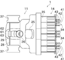
- the rice transplanter 1 includes a vehicle body portion 11, a front wheel 12, a rear wheel 13, and a planting portion 14.
- the front wheels 12 and the rear wheels 13 are provided in pairs with respect to the vehicle body portion 11, respectively.
- the vehicle body portion 11 is provided with a bonnet 21.
- the bonnet 21 is provided at the front portion of the vehicle body portion 11.
- An engine 22 is provided inside the bonnet 21.
- the power generated by the engine 22 is transmitted to the front wheels 12 and the rear wheels 13 via the mission case 23. This power is also transmitted to the planting portion 14 via the mission case 23 and the PTO shaft 24 arranged at the rear portion of the vehicle body portion 11.
- the vehicle body portion 11 further includes a driver's seat 25 for an operator to sit on, and a plurality of operating tools.
- the driver's seat 25 is arranged between the front wheels 12 and the rear wheels 13 in the front-rear direction of the vehicle body portion 11.
- the plurality of operating tools are, for example, a steering handle 26 and a speed change operation pedal 27.
- the direction of travel of the rice transplanter 1 is changed by operating the steering handle 26 by the operator.
- the speed change operation pedal 27 By operating the speed change operation pedal 27 by the operator, the traveling speed (vehicle speed) of the rice transplanter 1 is adjusted.
- the planting portion 14 is arranged behind the vehicle body portion 11.
- the planting portion 14 is connected to the vehicle body portion 11 via an elevating link mechanism 31.
- the elevating link mechanism 31 is composed of parallel links including a top link 31a and a lower link 31b.
- An elevating cylinder 32 is connected to the lower link 31b. As the elevating cylinder 32 expands and contracts, the planting portion 14 moves up and down with respect to the vehicle body portion 11.
- the elevating cylinder 32 is a hydraulic cylinder in this embodiment, it may be an electric cylinder.
- the planting unit 14 includes a planting input case unit 33, a plurality of planting units 34, a seedling stand 35, a plurality of floats 36, and a spare seedling stand 37.
- the planting unit 14 can sequentially supply seedlings from the seedling stand 35 to each planting unit 34 and continuously plant the seedlings.
- Each planting unit 34 has a planting transmission case portion 41 and a rotating case portion 42. Power is transmitted to the planting transmission case portion 41 via the PTO shaft 24 and the planting input case portion 33.
- the rotary case portion 42 is rotatably attached to the planting transmission case portion 41.
- the rotating case portions 42 are arranged on both sides of the planting transmission case portion 41 in the vehicle width direction.
- Two planting claws 43 are attached to one side of each rotating case portion 42.
- the two planting claws 43 are arranged in the traveling direction of the rice transplanter 1.
- the two planting claws 43 are displaced as the rotating case portion 42 rotates. By displacement of the two planting claws 43, one row of seedlings is planted.
- the seedling stand 35 is arranged in front of and above the plurality of planting units 34.
- the seedling mat can be placed on the seedling stand 35.
- the seedling stand 35 is configured so that the seedlings of the seedling mat placed on the seedling stand 35 can be supplied to each planting unit 34.
- the seedling stand 35 is configured to be laterally feedable (sliding in the lateral direction) so as to reciprocate in the vehicle width direction. Further, the seedling stand 35 is configured so that the seedling mat can be intermittently vertically fed downward at the reciprocating end of the seedling stand 35.
- the float 36 is swingably provided at the lower part of the planting portion 14.
- the float 36 can bring the lower surface of the float 36 into contact with the field surface in order to stabilize the planting posture of the planting portion 14 with respect to the field surface.
- the spare seedling stand 37 is provided in pairs with respect to the vehicle body portion 11.
- the spare seedling stand 37 is arranged outside the bonnet 21 in the vehicle width direction.
- the spare seedling stand 37 can be equipped with a seedling box containing spare mat seedlings.
- the upper parts of the pair of left and right spare seedling stands 37 are connected by a connecting frame 28 extending in the vertical direction and the vehicle width direction.
- a housing 29 is provided at the center of the connecting frame 28 in the vehicle width direction.
- a positioning antenna 61, an inertial measurement unit (IMU) 62, and a communication antenna 63 are provided inside the housing 29.
- the positioning antenna 61 can receive radio waves from the positioning satellites constituting the satellite positioning system (GNSS).
- GNSS satellite positioning system
- the position of the rice transplanter 1 can be acquired by performing a known positioning calculation based on this radio wave.
- the inertial measurement unit 62 has three gyro sensors (angular velocity sensors) and three acceleration sensors. The details of the information detected by the inertial measurement unit 62 and the initialization process of the inertial measurement unit 62 will be described later.
- the communication antenna 63 is an antenna for performing wireless communication with the wireless communication terminal 7 shown in FIG.
- the control unit 50 includes an arithmetic unit (not shown), a storage device, an input / output unit, and the like. Various programs, data, and the like are stored in the storage device. The arithmetic unit can read various programs from the storage device and execute them. By the cooperation of the hardware and software described above, the control unit 50 can be operated as the travel control unit 51, the work equipment control unit 52, the initialization control unit 53, and the condition setting unit 54.
- the control unit 50 may be one piece of hardware or a plurality of pieces of hardware that can communicate with each other. Further, in addition to the inertial measurement unit 62 described above, the control unit 50 is connected to a position acquisition unit 64, a communication processing unit 65, a vehicle speed sensor 66, and a steering angle sensor 67.
- the position acquisition unit 64 acquires the positioning information of the rice transplanter 1 as a mobile station based on the radio waves received by the positioning antenna 61 from the positioning satellite. More specifically, the position acquisition unit 64 acquires the pseudo distance from the positioning satellite to the positioning antenna 61 and the carrier phase when the radio wave reaches the positioning antenna 61 for each of the positioning satellites that have received the radio waves. .. This pseudo distance is obtained by multiplying the signal propagation time measured using the internal clock of the positioning satellite and the internal clock of the position acquisition unit 64 by the speed of light.
- the carrier wave phase is obtained by measuring the difference between the phase of the carrier wave received by the positioning antenna 61 and the phase output by the internal oscillator of the position acquisition unit 64.
- the position acquisition unit 64 acquires the positioning correction information generated based on the pseudo distance from the positioning satellite to the reference station 120 and the carrier phase when the reference station 120 is reached with respect to the reference station 120 whose position is known. To do. In the present embodiment, the position acquisition unit 64 acquires the positioning correction information by directly communicating between the reference station 120 and the rice transplanter 1. The position acquisition unit 64 may acquire positioning correction information via the Internet, a wireless communication terminal 7, or the like.
- the position acquisition unit 64 moves by performing a calculation by a known GNSS-RTK method using the positioning information which is the observed value obtained by the rice transplanter 1 and the positioning correction information generated by the reference station 120.
- the baseline solution between the rice transplanter 1 as a station and the reference station 120 is continuously calculated.
- the positioning solution which is the position of the rice transplanter 1
- both the rice transplanter 1 and the reference station 120 detect the carrier phase of the radio wave from the GNSS satellite and use it for the positioning calculation, so that the position of the rice transplanter 1 can be determined with significantly higher accuracy than the normal single positioning. Can be obtained.
- a positioning calculation using, for example, a differential GNSS may be performed.
- the communication processing unit 65 is electrically connected to the communication antenna 63.
- the communication processing unit 65 can perform modulation processing or demodulation processing by an appropriate method to transmit / receive data to / from the wireless communication terminal 7.
- the vehicle speed sensor 66 detects the vehicle speed of the rice transplanter 1.
- the vehicle speed sensor 66 is provided at an appropriate position of the rice transplanter 1, for example, on the axle of the front wheel 12. In this case, the vehicle speed sensor 66 generates a pulse according to the rotation of the axle of the front wheel 12.
- the detection result data obtained by the vehicle speed sensor 66 is output to the control unit 50.
- the steering angle sensor 67 detects the steering angle of the front wheels 12.
- the steering angle sensor 67 is provided at an appropriate position of the rice transplanter 1, for example, at a kingpin (not shown) provided on the front wheel 12.
- the steering angle sensor 67 may be provided on the steering handle 26.
- the detection result data obtained by the steering angle sensor 67 is output to the control unit 50.
- the travel control unit 51 automatically controls the travel of the rice transplanter 1.
- the travel control unit 51 can perform vehicle speed control and steering control.
- the travel control unit 51 may perform both vehicle speed control and steering control at the same time, or may perform only steering control. In the latter case, the vehicle speed of the rice transplanter 1 is operated by the operator using the speed change operation pedal 27.
- the vehicle speed of rice transplanter 1 is adjusted based on predetermined conditions. Specifically, the vehicle speed control is controlled by the traveling control unit 51 to bring the current vehicle speed obtained from the detection result of the vehicle speed sensor 66 closer to the target vehicle speed. This control is realized by changing at least one of the gear ratio of the transmission in the transmission case 23 and the rotation speed of the engine 22.
- the vehicle speed control also includes a control to set the vehicle speed to zero so that the rice transplanter 1 stops.
- Steering control is control that adjusts the rudder angle of the rice transplanter 1 based on predetermined conditions.
- the steering control unit 51 controls the current steering angle obtained from the detection result of the steering angle sensor 67 to approach the target steering angle. This control is realized, for example, by driving a steering actuator provided on the rotation shaft of the steering handle 26.
- the traveling control unit 51 may directly adjust the steering angle (wheel) of the front wheel 12 of the rice transplanter 1 instead of the rotation angle (steering angle) of the steering handle 26.
- the work machine control unit 52 can control the operation (elevation operation, planting work, etc.) of the planting unit 14 based on predetermined conditions.
- the processing performed by the initialization control unit 53 and the condition setting unit 54 will be described later.
- the wireless communication terminal 7 is a tablet terminal and includes a communication antenna 71, a communication processing unit 72, a display unit 73, an operation unit 74, a storage unit 75, and a calculation unit 80.
- the wireless communication terminal 7 is not limited to the tablet terminal, but may be a smartphone or a laptop computer.
- the wireless communication terminal 7 performs various processes related to the autonomous traveling of the rice transplanter 1, and the control unit 50 of the rice transplanter 1 may perform at least a part of these processes. On the contrary, the wireless communication terminal 7 may perform at least a part of various processes related to autonomous traveling performed by the control unit 50 of the rice transplanter 1.
- the communication antenna 71 is an antenna for short-range communication for wireless communication with the rice transplanter 1.
- the communication processing unit 72 is electrically connected to the communication antenna 71.
- the communication processing unit 72 performs modulation processing of the transmission signal, demodulation processing of the reception signal, and the like.
- either the rice transplanter 1 or the wireless communication terminal 7 is provided with a mobile phone line and a mobile communication antenna for performing communication using the Internet.
- a part of the information stored in the rice transplanter 1 or the wireless communication terminal 7 can be stored in an external server, or the information can be acquired from the external server.
- the display unit 73 is a liquid crystal display, an organic EL display, or the like, and is configured to be able to display an image.
- the display unit 73 can display, for example, information on autonomous driving, information on the setting of the rice transplanter 1, detection results of various sensors, warning information, and the like.
- the operation unit 74 includes a touch panel and a hardware key.
- the touch panel is arranged so as to overlap the display unit 73, and can detect an operation by an operator's finger or the like.
- the hardware key is arranged on the side surface of the housing of the wireless communication terminal 7 or around the display unit 73, and can be operated by being pressed by the operator.
- the wireless communication terminal 7 may be configured to include only one of a touch panel and a hardware key.
- the storage unit 75 is a non-volatile memory such as a flash memory or a hard disk.
- the storage unit 75 stores, for example, information about autonomous traveling.
- the arithmetic unit 80 is an arithmetic unit such as a CPU.
- the calculation unit 80 can read various programs from the storage unit 75 and execute them. By the cooperation of the above hardware and software, the calculation unit 80 can be operated as the display control unit 81 and the initialization instruction control unit 82. The processing performed by the display control unit 81 and the initialization instruction control unit 82 will be described later.
- the field includes a work area and a headland area.
- the work area is located in the central part of the field and is an area for performing work.
- the headland area is located outside the work area and is an area used for proper work in the work area.
- the headland area is used to move the rice transplanter 1 that has entered the field to the starting position of the work in the work area. Further, the headland area is also used as an area for turning the rice transplanter 1.
- the position and shape of the field are created based on the transition of the position information when the rice transplanter 1 is run along the outer circumference of the field.
- the position and shape of the field may be created by the user designating a range on a map displayed on the display unit 73 without actually running the rice transplanter 1.
- the information about the field is stored in the wireless communication terminal 7, but it may be stored in the server described above. In this case, the wireless communication terminal 7 acquires information about the field from this server.
- a traveling route 91 for autonomously traveling the rice transplanter 1 is created.
- the travel path 91 is created by, for example, the calculation unit 80.
- the traveling path 91 includes a plurality of straight paths 91a and a plurality of turning paths 91b. Further, a start position (S in FIG. 4) and an end position (G in FIG. 4) are set in the travel path 91.
- the traveling route 91 shown in FIG. 4 is an example, and the rice transplanter 1 can be autonomously traveled along a route having another feature.
- the inertial measurement unit 62 is a sensor unit capable of specifying the posture, acceleration, etc. of the rice transplanter 1. Specifically, the inertial measurement unit 62 includes a sensor group in which an angular velocity sensor and an acceleration sensor are attached to each of the first axis, the second axis, and the third axis that are orthogonal to each other.
- the inertial measurement unit 62 has a first acceleration sensor that detects the acceleration in the first axis direction, a second acceleration sensor that detects the acceleration in the second axis direction, and a second acceleration sensor that detects the acceleration in the third axis direction.
- a first angular velocity sensor that detects the angular velocity around the first axis
- a second angular velocity sensor that detects the angular velocity around the second axis
- a third angular velocity sensor that detects the angular velocity around the third axis.
- the first angular velocity sensor can detect the roll angular velocity of the rice transplanter 1
- the second angular velocity sensor can detect the pitch angular velocity of the rice transplanter 1
- the third angular velocity sensor can detect the yaw angular velocity of the rice transplanter 1.
- the direction is determined with respect to the machine 1, and it is attached to the position of the center of gravity of the rice transplanter 1.
- the first axis is arranged so as to coincide with the front-rear direction of the rice transplanter 1, that is, to be a roll rotation axis.
- the second axis is arranged so as to coincide with the left-right direction of the rice transplanter 1, that is, to be a pitch rotation axis.
- the third axis is arranged so as to coincide with the vertical direction of the rice transplanter 1, that is, to be the yaw rotation axis.
- the angular velocity (roll angular velocity, pitch angular velocity, and yaw angular velocity) of the attitude change of the rice planting machine 1 and the acceleration in the front-rear direction, the left-right direction, and the up-down direction can be specified. It has become like.
- the result of integrating the obtained angular velocities is used to acquire the posture of the rice transplanter 1.
- Information on the posture of the rice transplanter 1 is input to the control unit 50 and used for correcting the position information acquired by the position acquisition unit 64 or for other control.
- the position information is calculated by temporarily interrupting the radio waves from the GNSS satellite. If it becomes impossible, the position of the rice transplanter 1 in the meantime can be obtained.
- the angular velocity sensor of the inertial measurement unit 62 can detect the change in the orientation of the rice transplanter 1, but cannot detect the orientation itself of the rice transplanter 1. In particular, the angle (yaw angle) indicating which direction the rice transplanter 1 is facing cannot be obtained even if the gravitational acceleration is used as a clue.
- the rice transplanter 1 is actually moved straight in a predetermined direction (for example, forward or backward), and the position change of the rice transplanter 1 at this time is obtained by using GNSS radio waves, and the direction indicated by the position change is obtained.
- the yaw angle is calculated based on this.
- the process of determining the direction (yaw angle) at which the rice transplanter 1 faces in this way is called an initialization process, and the process of moving the rice transplanter 1 straight to perform the initialization process is called an initialization run.
- the vehicle speed and the mileage for performing the initialization running are predetermined.
- the initialization control unit 53 described above controls the initialization process.
- the condition setting unit 54 sets the conditions for starting the initialization process.
- the orientation detection unit may have a configuration different from that of the inertial measurement unit 62 of the present embodiment as long as it can detect at least the orientation of the rice transplanter 1 (specifically, the orientation with the vertical direction as the center of rotation). ..
- Patent Document 1 describes that the initialization process is performed only when the tractor is started. Further, Patent Document 1 describes that the operator manually performs the initialization running. Therefore, in the configuration of Patent Document 1, in order to perform the initialization process, it is necessary for the operator to board the tractor and turn on the power from off to on, and then the operator operates the tractor to perform the initialization traveling. In this respect, in the present embodiment, the operator can remotely instruct the initialization process without approaching the rice transplanter 1 while maintaining the power of the rice transplanter 1 turned on, and the initialization run is not performed manually. It can also be done autonomously. The details will be described below.
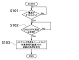
- the initialization process is performed when the rice transplanter 1 is started.
- the start-up time of the rice transplanter 1 indicates the time when the power supply of the rice transplanter 1 is switched from off to on (strictly speaking, until a predetermined time elapses after the rice transplanter 1 is switched on).
- the initialization control unit 53 determines whether or not the power supply of the rice transplanter 1 is switched from off to on (that is, whether or not it is immediately after the rice transplanter 1 is started). When the initialization control unit 53 determines that the power supply of the rice transplanter 1 has been switched from off to on, it determines whether or not GNSS-RTK positioning is effective (S102). GNSS-RTK positioning is effective when both the positioning information of the rice transplanter 1 as a mobile station and the positioning correction information generated by the reference station 120 are appropriately received and the calculation is performed by the GNSS-RTK method. Refers to the fact that Therefore, when GNSS-RTK positioning is effective, the position of the rice transplanter 1 can be acquired with high accuracy (predetermined accuracy).
- the position of the rice transplanter 1 cannot be acquired with high accuracy because GNSS-RTK is not effective.
- the position of the rice transplanter 1 can be acquired with low accuracy (less than a predetermined accuracy) by independent positioning.
- the initialization control unit 53 determines that the GNSS-RTK positioning is effective, the initialization control unit 53 performs the initialization process (S103). Specifically, the initialization control unit 53 instructs the travel control unit 51, and the travel control unit 51 sets the above-mentioned steering angle to neutral and advances the rice transplanter 1 straight (forward or backward) to perform initialization. I do. As described above, in the initialization running, the running control unit 51 can autonomously run the rice transplanter 1, but the operator may manually run the rice transplanter 1. Further, the initialization control unit 53 performs the initialization process of the inertial measurement unit 62 as described above during the initialization traveling. The value calculated in the initialization process is stored in the control unit 50 or the like and used for calculating the position and orientation of the rice transplanter 1.
- condition setting unit 54 sets that the power has been turned on from off as the first start condition of the initialization process. Further, in the present embodiment, it is also set that GNSS-RTK positioning is effective as another condition for starting the initialization process.
- the rice transplanter 1 may store the value calculated by the initialization process for a certain period of time even after the power is turned off. In this case, if it is clear that the orientation of the rice transplanter 1 has not changed while the power of the rice transplanter 1 is off (for example, when the rice transplanter 1 is restarted), the power of the rice transplanter 1 is turned off. Even when it is turned on, the value calculated in the previous initialization process may be used.
- the initialization control unit 53 determines whether or not the initialization process has been completed (S201). When the initialization process has been completed, it is not necessary to perform the initialization process, so the process related to autonomous driving (S206) is performed.
- the initialization control unit 53 determines whether or not GNSS-RTK positioning is effective, as in step S102 (S202). When the initialization control unit 53 determines that the GNSS-RTK positioning is effective, the initialization control unit 53 notifies the wireless communication terminal 7 to that effect. As a result, the display control unit 81 activates the initialization processing start button (S203).
- the initialization process start button is a button for the operator to instruct the start of the initialization process.
- the initialization process start button is a button on the GUI displayed on the display unit 73 of the wireless communication terminal 7.
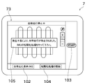
- FIG. 7 shows a screen displayed on the display unit 73 of the wireless communication terminal 7 during preparation for autonomous traveling.
- a work vehicle icon 101 indicating the position of the rice transplanter 1 is displayed on a map showing a field to be autonomously traveled.
- a determination result button 102 indicating the determination result of the autonomous traveling condition and an autonomous traveling start button 103 for starting the autonomous traveling are further displayed.
- the determination result button 102 displays whether or not the autonomous driving condition is satisfied. In the example shown in FIG. 7, since the autonomous traveling condition is not satisfied, "NG" is displayed.
- the autonomous travel start button 103 is a button for instructing the start of autonomous travel. In the example shown in FIG. 7, since the autonomous traveling condition is not satisfied, the autonomous traveling start button 103 is invalid (grayed out). By operating the determination result button 102, the screen shown in FIG. 8 is displayed.
- the screen of FIG. 8 shows the autonomous driving conditions in detail.
- the autonomous driving conditions are that the steering angle is neutral, the position of the work vehicle matches the start position of the traveling path, and the initialization process of the inertial measurement unit 62 (IMU) is completed. That is included. If the initialization process is not completed, the initialization process start button 104 is displayed in the vicinity thereof.
- the display position, display hierarchy, and the like of the initialization process start button 104 are examples.
- the initialization process start button 104 may be displayed on the screen shown in FIG. 7.
- the initialization process start button 104 is normally hidden, and is displayed when it is enabled in step S203. Instead of this, it is usually displayed in gray out or the like, and may be operable when it is enabled in step S203. Further, in the present embodiment, the initialization process start button 104 is a button on the GUI, but may be a hardware key of the wireless communication terminal 7. Further, the initialization process start button 104 may be provided not on the wireless communication terminal 7 but on another terminal owned by the operator, or may be provided on the rice transplanter 1.
- a signal instructing the start of the initialization process is transmitted from the calculation unit 80 (initialization instruction control unit 82) to the control unit 50 (initialization control unit 53).
- the initialization control unit 53 determines whether or not the initialization process start button 104 has been operated based on the presence or absence of reception of this signal (S204).
- the initialization control unit 53 performs the initialization process in the same manner as in step S103 (S205).
- the initialization process can be performed without turning off the power of the rice transplanter 1, no restart time is required, so that the initialization process can be performed easily in a short time. be able to. Further, if there is a setting that is deleted by turning off the power of the rice transplanter 1, the trouble of such setting can be reduced.
- the autonomous travel system 100 may perform the initialization travel manually or autonomously. However, by autonomously performing the initialization running, the labor of the operator can be reduced. In particular, when the rice transplanter 1 is autonomously driven unmanned (without the operator boarding the driver's seat 25), the time and effort for the operator to move to the rice transplanter 1 for the initialization running can be reduced.
- the driving permission conditions include, for example, (1) that there are no obstacles in the area passed during the initialization driving, (2) that the start of the initialization driving is notified by a warning sound or the like, and (3) the operator is in the driver's seat 25.
- the condition (3) can be detected by the driver's seat 25 or a seat switch provided below the driver's seat 25.
- This travel permission condition is applied not only to the initialization travel performed when the power of the rice transplanter 1 is on, but also to the initialization travel performed when the power of the rice transplanter 1 is switched from off to on.
- the initialization process needs to be performed with the power of the rice transplanter 1 (control unit 50) turned on.
- the rice transplanter 1 and the wireless communication terminal 7 can communicate only when the power of the rice transplanter 1 is turned on. That is, even if the initialization process start button 104 is operated when the power of the rice transplanter 1 is off, the initialization process is not performed.
- the initialization process start button 104 may be enabled only when the power of the rice transplanter 1 is on.
- the IMU initialization condition among the autonomous driving conditions will be satisfied.
- the autonomous driving start button 103 is enabled (grayout is canceled). Then, when it is detected that the autonomous travel start button 103 has been operated, the travel control unit 51 starts autonomous travel (S206).
- condition setting unit 54 sets that, as the second start condition of the initialization process, it has received an instruction to perform the initialization process (received a signal) when the power of the rice transplanter 1 is on. doing. Further, in the present embodiment, it is also set that GNSS-RTK positioning is effective as another condition for starting the initialization process.
- FIG. 10 shows a screen displayed on the display unit 73 during autonomous driving.
- the position and traveling route of the rice transplanter 1 in the field are shown.
- the autonomous traveling stop button 105 is displayed instead of the place where the autonomous traveling start button 103 is displayed. By operating the autonomous travel stop button 105, autonomous travel is stopped.
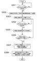
- the control unit 50 has detected whether or not GNSS-RTK positioning is effective (S301).
- positioning failure the fact that GNSS-RTK positioning is not effective is simply referred to as "positioning failure" or the like. As described above, when a positioning failure occurs, the position of the rice transplanter 1 cannot be acquired with high accuracy.
- the travel control unit 51 stops autonomous travel and stores the current position as a restart position (S302).
- the restart position is a position for restarting autonomous driving. That is, since the rice transplanter 1 moves by performing the initialization run, there is an area where the work is not performed. In order to prevent this, the autonomous traveling system 100 is configured to restart the autonomous traveling after returning the rice transplanter 1 to the restarting position.
- the initialization control unit 53 resets the completion state of this initialization process (S303). As a result, the set value obtained in the previously performed initialization process is deleted. Further, until a new initialization process is performed, the restart of the autonomous traveling of the rice transplanter 1 along the traveling route 91 is prohibited.
- the display control unit 81 of the wireless communication terminal 7 displays a message to that effect on the display unit 73 (see FIG. 11). This message may include that initialization processing is required, as shown in FIG. Further, the display control unit 81 displays the initialization process start button 104 on the display unit 73. As shown in FIG. 11, the initialization process start button 104 is not activated until the positioning defect is resolved.
- the display control unit 81 activates the initialization process start button 104 by canceling the grayout of the initialization process start button 104 (S305). Further, when the initialization process start button 104 is operated (S306), the initialization instruction control unit 82 transmits a signal instructing the start of the initialization process to the control unit 50. When the initialization control unit 53 determines that this signal has been received, the initialization control unit 53 performs the initialization run and initializes the inertial measurement unit 62 (S307) in the same manner as in step S205. The points regarding the travel permission conditions are the same as those in step S205.
- the traveling control unit 51 autonomously moves the rice transplanter 1 to the restart position and starts autonomous traveling from the restart position (S308). ).
- the second start condition of the initialization process is the same both during the preparation for autonomous driving and when the autonomous driving is stopped.
- the autonomous travel system 100 of the present embodiment includes a position acquisition unit 64, an inertial measurement unit 62, a travel control unit 51, an initialization control unit 53, and a condition setting unit 54. ..
- the position acquisition unit 64 acquires the position of the rice transplanter 1 using a satellite positioning system.
- the inertial measurement unit 62 detects the orientation of the rice transplanter 1.
- the travel control unit 51 autonomously causes the rice transplanter 1 to travel along a preset travel path 91.
- the initialization control unit 53 obtains the direction of the rice transplanter 1 based on the acquired value of the position acquisition unit 64 while the rice transplanter 1 is performing the initialization traveling straight in a predetermined direction, so that the inertial measurement unit 62 Initialization process of.
- the condition setting unit 54 is set that the power supply of the rice transplanter 1 is switched from off to on as the first start condition of the initialization process, and the power supply of the rice transplanter 1 is set as the second start condition of the initialization process. It is set that an instruction to perform initialization processing is accepted when it is on.
- the initialization process can be performed by giving a separate instruction. it can. Therefore, since the initialization process can be performed without turning off the power of the rice transplanter 1, the initialization process of the inertial measurement unit 62 can be easily performed.
- the rice transplanter 1 is autonomously initialized and run.
- the rice transplanter 1 can be autonomously driven to perform the initialization process, so that the operator's labor can be reduced as compared with the case where the operator manually drives the rice transplanter 1.
- the travel control unit 51 stops autonomous travel along the travel route when the position acquisition unit 64 cannot acquire the position of the rice transplanter 1 with a predetermined accuracy. ..
- the initialization control unit 53 resets the initialization completion state when the position acquisition unit 64 cannot acquire the position of the rice transplanter 1 with a predetermined accuracy.
- the travel control unit 51 satisfies the first start condition or the second start condition, and the travel permission condition is satisfied, the rice transplanter 51 can plant the rice.
- the machine 1 is autonomously initialized and run.
- the rice transplanter 1 can be autonomously driven to perform initialization processing, so that the operator's labor can be reduced.
- the traveling control unit 51 sets a position at which the position acquisition unit 64 cannot acquire the position of the rice transplanter 1 with a predetermined accuracy and stops the autonomous traveling as a restart position. After the initialization process is completed, the rice transplanter 1 is autonomously driven to the restart position.
- an instruction to perform initialization processing is transmitted from a wireless communication terminal 7 provided separately from the rice transplanter 1.
- the flowchart shown in the above embodiment is an example, and some processes may be omitted, the contents of some processes may be changed, or new processes may be added. For example, when the initialization running is performed autonomously, a process for displaying the fact on the display unit 73 may be added. Further, after the initialization process start button is operated, it may be determined again whether or not GNSS-RTK positioning is effective.
- the initialization process start button 104 may be enabled when the travel permission condition is satisfied.
- the completed state of the previous initialization process is automatically reset when the positioning is defective, but the completed state may be reset in response to an operator's instruction.
- the button for instructing the reset of the previous initialization process and the button for instructing the start of the new initialization process may be separated.
- the configuration may be such that these two processes are performed by operating one button.
Landscapes
- Engineering & Computer Science (AREA)
- Life Sciences & Earth Sciences (AREA)
- Radar, Positioning & Navigation (AREA)
- Remote Sensing (AREA)
- Soil Sciences (AREA)
- Environmental Sciences (AREA)
- Automation & Control Theory (AREA)
- Aviation & Aerospace Engineering (AREA)
- Physics & Mathematics (AREA)
- General Physics & Mathematics (AREA)
- Mechanical Engineering (AREA)
- Business, Economics & Management (AREA)
- Health & Medical Sciences (AREA)
- Artificial Intelligence (AREA)
- Evolutionary Computation (AREA)
- Game Theory and Decision Science (AREA)
- Medical Informatics (AREA)
- Guiding Agricultural Machines (AREA)
- Control Of Position, Course, Altitude, Or Attitude Of Moving Bodies (AREA)
Abstract
この自律走行システムは、位置取得部と、慣性計測装置と、走行制御部と、初期化制御部と、条件設定部と、を備える。位置取得部は、衛星測位システムを用いて作業車両の位置を取得する。慣性計測装置は、作業車両の向きを検出する。走行制御部は、予め設定された走行経路に沿って作業車両を自律走行させる。初期化制御部は、作業車両が所定方向に直進する初期化走行を行っている間の位置取得部の取得値に基づいて当該作業車両の向きを求めることで、慣性計測装置の初期化処理を行う。条件設定部は、初期化処理の第1開始条件として作業車両の電源がオフからオンに切り替わったことが設定されており、初期化処理の第2開始条件として作業車両の電源がオンであるときに初期化処理を行う指示を受け付けたことが設定されている。
Description
本発明は、主として、作業車両を自律走行させる自律走行システムに関する。
従来から、GNSS衛星から受信した電波に基づいて作業車両の位置情報を取得し、予め設定された経路に沿って作業車両を自律的に走行させる自律走行システムが知られている。このような自律走行を実現するためには、作業車両の向きが、作業車両を自律走行させる自律走行制御部によって把握されていることが必要である。
特許文献1では、GNSS衛星から電波を受信できる構成を作業車両が備えていることを利用し、作業車両を前進又は後進させるようにユーザに手動運転させ、このときの作業車両の位置の変化をGNSS衛星の電波に基づいて検出する。そして、作業車両の位置が変化した向き又はその反対向きを作業車両の向きとみなして、作業車両の向き(方位)を検出する。以下では、この処理を初期化処理と称する。
特許文献1には、作業車両(トラクタ)の起動時において、所定条件を満たした場合に初期化処理を行うことが記載されている。しかし、特許文献1には、それ以外のタイミングで初期化処理を行うことは記載されていない。
本発明は以上の事情に鑑みてされたものであり、その主要な目的は、初期化処理を簡単に行うことが可能な自律走行システムを提供することにある。
本発明の解決しようとする課題は以上の如くであり、次にこの課題を解決するための手段とその効果を説明する。
本発明の観点によれば、以下の構成の自律走行システムが提供される。即ち、この自律走行システムは、位置取得部と、向き検出部と、走行制御部と、初期化制御部と、条件設定部と、を備える。前記位置取得部は、衛星測位システムを用いて作業車両の位置を取得する。前記向き検出部は、前記作業車両の向きを検出する。前記走行制御部は、予め設定された走行経路に沿って前記作業車両を自律走行させる。前記初期化制御部は、前記作業車両が所定方向に直進する初期化走行を行っている間の前記位置取得部の取得値に基づいて当該作業車両の向きを求めることで、前記向き検出部の初期化処理を行う。前記条件設定部には、前記初期化処理の第1開始条件として前記作業車両の電源がオフからオンに切り替わったことが設定されており、前記初期化処理の第2開始条件として前記作業車両の電源がオンであるときに前記初期化処理を行う指示を受け付けたことが設定されている。
これにより、作業車両の電源がオフからオンになった場合だけでなく、作業車両の電源がオンを維持している場合においても、別途指示を行うことで初期化処理を行わせることができる。従って、作業車両の電源をオフにする処理を行うことなく初期化処理を行うことが可能となるので、向き検出部の初期化処理を簡単に行うことができる。
前記の自律走行システムにおいては、前記走行制御部は、前記初期化処理が完了しておらず、前記第1開始条件又は前記第2開始条件を満たし、かつ、走行許可条件を満たす場合は、前記作業車両を自律的に前記初期化走行させることが好ましい。
これにより、作業車両を自律走行させて初期化処理を行うことができるので、オペレータが手動で作業車両を走行させる場合と比較して、オペレータの手間を軽減できる。
前記の自律走行システムにおいては、以下の構成とすることが好ましい。即ち、前記走行制御部は、前記位置取得部が前記作業車両の位置を所定の精度で取得できなくなった場合に、前記走行経路に沿った自律走行を停止させる。前記初期化制御部は、前記位置取得部が前記作業車両の位置を所定の精度で取得できなくなった場合に、初期化完了状態をリセットする。前記走行制御部は、前記位置取得部が前記作業車両の位置を所定の精度で取得できるようになり、前記第1開始条件又は前記第2開始条件を満たし、かつ、走行許可条件を満たす場合に、前記作業車両を自律的に前記初期化走行させる。
これにより、衛星測位等に失敗した場合であっても、作業車両を自律走行させて初期化処理を行うことができるので、オペレータの手間を軽減できる。
前記の自律走行システムにおいては、前記走行制御部は、前記位置取得部が前記作業車両の位置を所定の精度で取得できなくなって自律走行を停止させた位置を再開位置として設定し、前記初期化処理の完了後に、前記再開位置まで前記作業車両を自律走行させることが好ましい。
これにより、初期化走行によって位置が変化した後においても、初期化走行を行う前の再開位置から作業を再開できる。
前記の自律走行システムにおいては、前記初期化処理を行う指示は、前記作業車両とは別に設けられた無線通信端末から送信されることが好ましい。
これにより、遠隔で初期化処理を実行させることができる。
次に、図面を参照して本発明の実施の形態を説明する。図1は、本発明の一実施形態に係る自律走行システム100で用いられる田植機1の側面図である。図2は、田植機1の平面図である。図3は、田植機1及び無線通信端末7のブロック図である。
本実施形態の自律走行システム100は、圃場内で田植え(苗の植付け)を行う田植機1に自律走行を行わせるためのシステムである。自律走行とは、田植機1が備える制御装置により走行に関する装置が制御されることで、予め定められた経路に沿うように少なくとも操舵が自律的に行われることを意味する。また、操舵に加え、車速又は作業機による作業等が自律的に行われる構成であってもよい。自律走行には、田植機1に人が乗っている場合と、田植機1に人が乗っていない場合が含まれる。なお、本発明における作業車両は、田植機1に限定されるものではなく、例えば、播種機、トラクタ、コンバイン等であってもよい。
図1及び図2に示すように、田植機1は、車体部11と、前輪12と、後輪13と、植付部14と、を備えている。前輪12及び後輪13は、それぞれ、車体部11に対して左右1対で設けられている。
車体部11は、ボンネット21を備えている。ボンネット21は、車体部11の前部に設けられている。ボンネット21の内部には、エンジン22が設けられている。
エンジン22が発生させた動力は、ミッションケース23を介して前輪12及び後輪13に伝達される。この動力は、ミッションケース23と、車体部11の後部に配置されたPTO軸24と、を介して、植付部14にも伝達される。
車体部11は、オペレータが座るための運転座席25と、複数の操作具と、を更に備えている。運転座席25は、車体部11の前後方向において前輪12と後輪13の間に配置されている。複数の操作具は、例えば、操舵ハンドル26及び変速操作ペダル27である。
オペレータによって操舵ハンドル26が操作されることで、田植機1の進行方向が変更される。オペレータによって変速操作ペダル27が操作されることで、田植機1の走行速度(車速)が調節される。
植付部14は、車体部11の後方に配置されている。植付部14は、昇降リンク機構31を介して車体部11に連結されている。昇降リンク機構31は、トップリンク31a及びロワーリンク31bを含む平行リンクにより構成されている。
ロワーリンク31bには、昇降シリンダ32が連結されている。昇降シリンダ32が伸縮することによって、車体部11に対して植付部14が上下に昇降する。なお、昇降シリンダ32は、本実施形態においては油圧シリンダとしているが、電動シリンダとしてもよい。
植付部14は、植付入力ケース部33と、複数の植付ユニット34と、苗載台35と、複数のフロート36と、予備苗台37と、を備えている。植付部14は、各植付ユニット34に対して苗載台35から苗を順次供給し、苗の植付けを連続的に行うことができる。
各植付ユニット34は、植付伝動ケース部41と、回転ケース部42と、を有している。植付伝動ケース部41には、PTO軸24及び植付入力ケース部33を介して動力が伝達される。
回転ケース部42は、植付伝動ケース部41に回転可能に取り付けられている。回転ケース部42は、植付伝動ケース部41の車幅方向の両側に配置されている。各回転ケース部42の一側には、2つの植付爪43が取り付けられている。
2つの植付爪43は、田植機1の進行方向に並べられている。2つの植付爪43は、回転ケース部42の回転に伴い変位する。2つの植付爪43が変位することにより、1条分の苗の植付が行われる。
苗載台35は、複数の植付ユニット34の前上方に配置されている。苗載台35は、苗マットを載置可能である。苗載台35は、当該苗載台35に載置された苗マットの苗を各植付ユニット34に対して供給できるように構成されている。
具体的には、苗載台35は、車幅方向に往復するように横送り移動可能に(横方向にスライド可能に)構成されている。また、苗載台35は、当該苗載台35の往復移動端で苗マットを間欠的に下方に縦送り搬送可能に構成されている。
フロート36は、植付部14の下部に揺動可能に設けられている。フロート36は、植付部14の植付姿勢を圃場表面に対して安定させるために、当該フロート36の下面を圃場表面に接触させることができる。
予備苗台37は、車体部11に対して左右1対で設けられている。予備苗台37は、ボンネット21の車幅方向外側に配置されている。予備苗台37は、予備のマット苗を収容した苗箱を搭載可能である。
左右1対の予備苗台37の上部同士は、上下方向及び車幅方向に延びる連結フレーム28によって連結されている。連結フレーム28の車幅方向の中央に、筐体29が設けられている。筐体29の内部には、測位アンテナ61と、慣性計測装置(IMU)62と、通信アンテナ63と、が設けられている。
測位アンテナ61は、衛星測位システム(GNSS)を構成する測位衛星からの電波を受信することができる。この電波に基づいて公知の測位計算が行われることにより、田植機1の位置を取得することができる。
慣性計測装置62は、3つのジャイロセンサ(角速度センサ)と、3つの加速度センサと、を有している。なお、慣性計測装置62が検出する情報の詳細、及び、慣性計測装置62の初期化処理については後述する。
通信アンテナ63は、図3に示す無線通信端末7と無線通信を行うためのアンテナである。
制御部50は、図示しない演算装置、記憶装置、及び入出力部等を備える。記憶装置には、各種のプログラム及びデータ等が記憶されている。演算装置は、各種のプログラムを記憶装置から読み出して実行することができる。上記のハードウェアとソフトウェアの協働により、制御部50を、走行制御部51、作業機制御部52、初期化制御部53、及び条件設定部54として動作させることができる。制御部50は、1つのハードウェアであってもよいし、互いに通信可能な複数のハードウェアであってもよい。また、制御部50には、上記の慣性計測装置62に加え、位置取得部64と、通信処理部65と、車速センサ66と、舵角センサ67と、が接続されている。
位置取得部64は、測位衛星から測位アンテナ61が受信した電波に基づいて、移動局としての田植機1の測位情報を取得する。より詳細には、位置取得部64は、電波を受信した測位衛星のそれぞれについて、測位衛星から測位アンテナ61までの擬似距離と、電波が測位アンテナ61に到達したときの搬送波位相と、を取得する。この擬似距離は、測位衛星の内部時計と、位置取得部64の内部時計と、を用いて計測された信号伝搬時間に光速を乗じることにより得られる。また、搬送波位相は、測位アンテナ61で受信された搬送波の位相と、位置取得部64の内部発振器が出力する位相と、の差を測定することにより得られる。
加えて、位置取得部64は、位置が既知の基準局120に関して、測位衛星から基準局120までの擬似距離と、基準局120に到達したときの搬送波位相と、に基づいて生成された測位補正情報を取得する。本実施形態では、基準局120と田植機1とが直接通信を行うことで、位置取得部64が測位補正情報を取得する。なお、位置取得部64は、インターネット及び無線通信端末7等を介して測位補正情報を取得してもよい。
位置取得部64は、田植機1で得られた観測値である測位情報と、基準局120で生成された測位補正情報と、を用いて、公知のGNSS-RTK法による計算を行うことにより、移動局としての田植機1と、基準局120と、の間の基線解を連続的に算出する。これにより、田植機1の位置である測位解がリアルタイムで求められる。GNSS-RTK法では、田植機1と基準局120の双方でGNSS衛星からの電波の搬送波位相を検出して測位計算に用いるので、通常の単独測位よりも著しく高い精度で、田植機1の位置を取得することができる。なお、GNSS-RTK法に代えて、例えばディファレンシャルGNSSを用いた測位演算が行われてもよい。
通信処理部65は、通信アンテナ63に電気的に接続されている。この通信処理部65は、適宜の方式で変調処理又は復調処理を行って、無線通信端末7との間でデータの送受信を行うことができる。
車速センサ66は、田植機1の車速を検出する。車速センサ66は、田植機1の適宜の位置、例えば前輪12の車軸に設けられる。この場合、車速センサ66は、前輪12の車軸の回転に応じたパルスを発生させる。車速センサ66で得られた検出結果のデータは、制御部50へ出力される。
舵角センサ67は、前輪12の舵角を検出する。舵角センサ67は、田植機1の適宜の位置、例えば前輪12に設けられた図示しないキングピンに設けられる。なお、舵角センサ67は、操舵ハンドル26に設けられてもよい。舵角センサ67で得られた検出結果のデータは、制御部50へ出力される。
走行制御部51は、田植機1の走行に関する自動制御を行う。例えば、走行制御部51は、車速制御及び操舵制御を行うことができる。走行制御部51は、車速制御及び操舵制御の両方を同時に行ってもよいし、操舵制御のみを行うようにしてもよい。後者の場合、田植機1の車速は、オペレータが変速操作ペダル27を用いて操作する。
車速制御では、予め定められた条件に基づいて田植機1の車速が調整される。車速制御は、具体的には、走行制御部51が、車速センサ66の検出結果により得られた現在の車速を目標の車速に近づける制御を行う。この制御は、ミッションケース23内の変速装置の変速比、及び、エンジン22の回転速度のうち、少なくとも一方を変更することにより実現される。なお、この車速制御は、田植機1が停止するように車速をゼロにする制御も含む。
操舵制御とは、予め定められた条件に基づいて田植機1の舵角を調整する制御である。操舵制御は、具体的には、走行制御部51が、舵角センサ67の検出結果により得られた現在の舵角を目標の舵角に近づける制御を行う。この制御は、例えば、操舵ハンドル26の回転軸に設けられた操舵アクチュエータを駆動することにより実現される。なお、操舵制御に関しては、走行制御部51が、操舵ハンドル26の回動角度(ステアリング角度)ではなく、田植機1の前輪12の操舵角(車輪)を直接調整してもよい。
作業機制御部52は、予め定められた条件に基づいて植付部14の動作(昇降動作又は植付作業等)を制御可能である。なお、初期化制御部53及び条件設定部54が行う処理は後述する。
無線通信端末7は、タブレット端末であり、通信アンテナ71と、通信処理部72と、表示部73と、操作部74と、記憶部75と、演算部80と、を備える。なお、無線通信端末7はタブレット端末に限るものではなく、スマートフォン又はノートパソコンであってもよい。無線通信端末7は、田植機1の自律走行に関する様々な処理を行うが、これらの処理の少なくとも一部を田植機1の制御部50が行ってもよい。逆に、田植機1の制御部50が行う自律走行に関する様々な処理の少なくとも一部を無線通信端末7が行ってもよい。
通信アンテナ71は、田植機1と無線通信を行うための近距離通信用のアンテナである。通信処理部72は、通信アンテナ71に電気的に接続されている。通信処理部72は、送信信号の変調処理又は受信信号の復調処理等を行う。また、田植機1又は無線通信端末7の何れか一方は、携帯電話回線及びインターネットを利用した通信を行うための携帯通信用アンテナを備える。これにより、例えば田植機1又は無線通信端末7に記憶される情報の一部を外部のサーバに記憶させたり、外部のサーバから情報を取得したりすることができる。
表示部73は、液晶ディスプレイ又は有機ELディスプレイ等であり、画像を表示可能に構成されている。表示部73は、例えば、自律走行に関する情報、田植機1の設定に関する情報、各種センサの検出結果、及び警告情報等を表示することができる。
操作部74は、タッチパネルと、ハードウェアキーと、を含んでいる。タッチパネルは、表示部73に重ねて配置されており、オペレータの指等による操作を検出可能である。ハードウェアキーは、無線通信端末7の筐体の側面又は表示部73の周囲等に配置されており、オペレータが押圧することで操作可能である。なお、無線通信端末7は、タッチパネルとハードウェアキーの何れか一方のみを備える構成であってもよい。
記憶部75は、フラッシュメモリ又はハードディスク等の不揮発性メモリである。記憶部75には、例えば、自律走行に関する情報が記憶されている。
演算部80は、CPU等の演算装置である。演算部80は、各種のプログラムを記憶部75から読み出して実行することができる。この上記のハードウェアとソフトウェアの協働により、演算部80を、表示制御部81及び初期化指示制御部82として動作させることができる。表示制御部81及び初期化指示制御部82が行う処理は後述する。
次に、図4を参照して、圃場及び自律走行用の走行経路について説明する。圃場には、作業領域と枕地領域とが含まれている。作業領域は圃場の中央部に位置しており、作業を行うための領域である。枕地領域は、作業領域の外側に位置しており、作業領域で適切に作業を行うために使用される領域である。例えば、枕地領域は、圃場に進入した田植機1を作業領域での作業の開始位置に移動させるために用いられる。更に、枕地領域は、田植機1を旋回させるための領域としても用いられる。
圃場の位置及び形状は、田植機1を圃場の外周に沿って走行させた際の位置情報の推移に基づいて作成されている。なお、田植機1を実際に走行させずに、例えば表示部73に表示された地図上でユーザが範囲を指定することで、圃場の位置及び形状が作成されてもよい。また、本実施形態では圃場に関する情報は無線通信端末7に記憶されているが、上述したサーバに記憶されていてもよい。この場合、無線通信端末7は、このサーバから圃場に関する情報を取得する。
本実施形態では、田植機1を自律走行させるための走行経路91が作成される。走行経路91は、例えば演算部80によって作成される。図4に示すように、走行経路91は、複数の直線経路91a及び複数の旋回経路91bを含んで構成されている。また、走行経路91には、開始位置(図4のS)と、終了位置(図4のG)と、が設定される。なお、図4に示す走行経路91は一例であり、別の特徴を有する経路に沿って田植機1を自律走行させることもできる。
次に、慣性計測装置62について更に詳細に説明する。
慣性計測装置62は、田植機1の姿勢や加速度等を特定することが可能なセンサユニットである。具体的には、慣性計測装置62は、互いに直交する第1軸、第2軸、及び第3軸のそれぞれに対して、角速度センサと加速度センサとを取り付けたセンサ群を備える。
詳述すると、慣性計測装置62は、第1軸方向の加速度を検出する第1加速度センサと、第2軸方向の加速度を検出する第2加速度センサと、第3軸方向の加速度を検出する第3加速度センサと、前記第1軸回りの角速度を検出する第1角速度センサと、前記第2軸回りの角速度を検出する第2角速度センサと、第3軸回りの角速度を検出する第3角速度センサと、を備えるものである。
慣性計測装置62は、第1角速度センサが田植機1のロール角速度を、第2角速度センサが田植機1のピッチ角速度を、第3角速度センサが田植機1のヨー角速度を検出できるように、田植機1に対して方向が定められて、田植機1の重心位置に取り付けられている。言い換えれば、第1軸は、田植機1の前後方向と一致するように、即ちロール回転軸となるように配置される。第2軸は、田植機1の左右方向と一致するように、即ちピッチ回転軸となるように配置される。第3軸は、田植機1の上下方向と一致するように、即ちヨー回転軸となるように配置される。
このような構成の慣性計測装置62の検出結果により、田植機1の姿勢変化の角速度(ロール角速度、ピッチ角速度、及びヨー角速度)、並びに、前後方向、左右方向、及び上下方向の加速度を特定できるようになっている。そして、得られた角速度を積分した結果が、田植機1の姿勢を取得するために用いられる。田植機1の姿勢に関する情報は制御部50に入力されて、位置取得部64が取得した位置情報を補正するのに用いたり、その他の制御に用いられたりする。
また、慣性計測装置62で取得された田植機1の姿勢変化及び加速度に関する情報を用いて公知の慣性航法演算を行うことにより、GNSS衛星からの電波が一時的に途切れる等して位置情報を算出できなくなった場合に、その間の田植機1の位置を求めることができる。
このような構成の田植機1に適切に自律走行を行わせるためには、田植機1の位置情報が制御部50によって正確に把握されているだけでは足りず、田植機1の向きが制御部50によって正確に把握されていることが必要である。この点、慣性計測装置62の角速度センサは、田植機1の向きの変化を検出することはできるが、田植機1の向きそのものを検出することはできない。特に、田植機1がどの方位を向いているかを示す角度(ヨー角)に関しては、重力加速度を手掛かりにしても求めることができない。
そこで、本実施形態では、田植機1を所定方向(例えば前又は後)に実際に直進させるとともに、GNSS電波を用いてこのときの田植機1の位置変化を求め、当該位置変化が示す向きに基づいてヨー角を求めることとしている。このようにして田植機1が向く方位(ヨー角)を求める処理を初期化処理と称し、初期化処理を行うために田植機1を直進させることを初期化走行と称する。また、初期化走行を行うための車速及び走行距離は予め定められている。上述の初期化制御部53は、初期化処理に関する制御を行う。条件設定部54は、初期化処理を開始するための条件を設定する。
なお、向き検出部は、少なくとも田植機1の向き(詳細には上下方向を回転中心とした向き)を検出可能であれば、本実施形態の慣性計測装置62とは異なる構成であってもよい。
特許文献1には、トラクタの起動時のみに初期化処理を行うことが記載されている。また、特許文献1には、オペレータが手動で初期化走行を行うことが記載されている。そのため、特許文献1の構成において、初期化処理を行うためには、オペレータがトラクタに搭乗して電源をオフからオンにし、その後にオペレータがトラクタを操作して初期化走行を行う必要がある。この点、本実施形態では、田植機1の電源をオンにした状態を維持しつつ、オペレータが田植機1に近づくことなく遠隔で初期化処理を指示可能であり、初期化走行を手動ではなく自律的に行うことも可能である。以下、詳細に説明する。
初めに、図5を参照して、田植機1の起動時に慣性計測装置62の初期化処理を行う流れについて説明する。
本実施形態の自律走行システム100では、特許文献1と同様、田植機1の起動時にも初期化処理が行われる。田植機1の起動時とは、田植機1の電源がオフからオンに切り替わった時(厳密にはオンに切り替わった後に所定時間が経過するまで)を示す。
初期化制御部53は、田植機1の電源がオフからオンに切り替わったか否か(即ち、田植機1が起動した直後であるか否か)を判定している。初期化制御部53は、田植機1の電源がオフからオンに切り替わったと判定した場合、GNSS-RTK測位が有効か否かを判定する(S102)。GNSS-RTK測位が有効とは、移動局としての田植機1の測位情報と、基準局120で生成された測位補正情報と、の両方を適切に受信して、GNSS-RTK法による計算を行うことができていることを指す。従って、GNSS-RTK測位が有効である場合、田植機1の位置を高い精度(所定の精度)で取得できる。一方、障害物等により田植機1の測位情報及び測位補正情報の何れかが取得できない場合、GNSS-RTKが有効ではないため、田植機1の位置を高い精度で取得できない。なお、単独測位による低い精度で(所定の精度以下で)田植機1の位置を取得できる可能性はある。
GNSS-RTK測位が有効でない場合、初期化処理を適切に行うことができない。従って、初期化制御部53は、GNSS-RTK測位が有効であると判定した場合、初期化処理を行う(S103)。具体的には、初期化制御部53は走行制御部51に指示し、走行制御部51は、上述のステアリング角度をニュートラルにして、田植機1を直進(前進又は後進)させることで初期化走行を行う。このように、初期化走行は、走行制御部51が田植機1を自律的に走行させることが可能であるが、オペレータが手動で田植機1を走行させてもよい。また、初期化制御部53は、初期化走行中において、上述したように慣性計測装置62の初期化処理を行う。初期化処理で算出された値は制御部50等に記憶され、田植機1の位置及び向きの算出に用いられる。
このように、条件設定部54は、初期化処理の第1開始条件として、電源がオフからオンになったことを設定している。また、本実施形態では、初期化処理を開始するための別の条件として、GNSS-RTK測位が有効であることも設定されている。なお、田植機1は、電源がオフになった後も一定時間は初期化処理で算出した値を記憶してもよい。この場合、田植機1の電源がオフの間に田植機1の向きが変化していないことが明らかである場合(例えば田植機1が再起動した場合)は、田植機1の電源がオフからオンになった場合でも、以前の初期化処理で算出した値を用いてもよい。
次に、図6から図8を参照して、田植機1の電源がオンになった後であって、かつ、自律走行の開始前において、初期化処理を行う流れについて説明する。具体的な状況としては、自律走行の準備中に測位不良等が発生し、慣性計測装置62の初期化処理を再び行わないと田植機1の自律走行が実行できない状況を想定している。
初期化制御部53は、初期化処理が完了済みか否かを判定する(S201)。初期化処理が完了済みである場合は、初期化処理を行う必要がないため、自律走行に関する処理(S206)を行う。
初期化制御部53は、初期化処理が完了済みでない場合、ステップS102と同様に、GNSS-RTK測位が有効か否かを判定する(S202)。初期化制御部53は、GNSS-RTK測位が有効と判断した場合、無線通信端末7にその旨を伝達する。その結果、表示制御部81は、初期化処理開始ボタンの有効化を行う(S203)。
初期化処理開始ボタンは、オペレータが初期化処理の開始を指示するためのボタンである。本実施形態では、初期化処理開始ボタンは、無線通信端末7の表示部73に表示されるGUI上のボタンである。以下、初期化処理の開始ボタンの表示について図7及び図8を参照して具体的に説明する。図7には、自律走行の準備中に無線通信端末7の表示部73に表示される画面が示されている。この画面には、自律走行の対象となる圃場を示す地図上に、田植機1の位置を示す作業車両アイコン101が表示されている。また、この画面には、更に、自律走行条件の判定結果を示す判定結果ボタン102と、自律走行を開始するための自律走行開始ボタン103と、が表示されている。
判定結果ボタン102は、自律走行条件を満たすか否かを表示する。図7に示す例では、自律走行条件を満たさないため、「NG」と表示されている。自律走行開始ボタン103は、自律走行の開始を指示するためのボタンである。図7に示す例では、自律走行条件が満たされていないので、自律走行開始ボタン103が無効(グレーアウト)となっている。判定結果ボタン102を操作することで、図8に示す画面が表示される。
図8の画面には、自律走行条件について詳細に示されている。本実施形態では、自律走行条件として、ステアリング角度がニュートラルであること、作業車両位置が走行経路の開始位置と一致していること、慣性計測装置62(IMU)の初期化処理が完了していることが含まれている。また、初期化処理が完了していない場合、その近傍に初期化処理開始ボタン104が表示される。なお、初期化処理開始ボタン104の表示位置、表示階層等は一例であり、例えば図7に示す画面に初期化処理開始ボタン104が表示されてもよい。
本実施形態では、初期化処理開始ボタン104は、通常は非表示であり、ステップS203で有効化した場合に表示される。これに代えて、普段はグレーアウト等で表示されており、ステップS203で有効化した場合に操作可能となってもよい。また、本実施形態では、初期化処理開始ボタン104はGUI上のボタンであるが、無線通信端末7のハードウェアキーであってもよい。また、初期化処理開始ボタン104は、無線通信端末7ではなく、オペレータが所持する他の端末に設けられてもよいし、田植機1に設けられてもよい。
初期化処理開始ボタン104が操作されることで、初期化処理の開始を指示する信号が演算部80(初期化指示制御部82)から制御部50(初期化制御部53)へ送信される。初期化制御部53は、この信号の受信の有無に基づいて、初期化処理開始ボタン104が操作されたか否かを判定する(S204)。初期化制御部53は、初期化処理開始ボタン104が操作されたと判定した場合、ステップS103と同様に初期化処理を行う(S205)。
このように、本実施形態では、田植機1の電源をオフにすることなく初期化処理が可能であるため、再起動の時間が不要であるため、短い時間でかつ簡単に初期化処理を行うことができる。また、田植機1の電源をオフにすることで削除される設定がある場合は、このような設定の手間も軽減できる。
自律走行システム100は、初期化走行を手動で行ってもよいし、自律的に行ってもよい。ただし、初期化走行を自律的に行うことで、オペレータの手間を軽減できる。特に、田植機1を無人で(運転座席25にオペレータが搭乗せずに)自律走行させる場合、オペレータが初期化走行のために田植機1まで移動する手間も低減できる。
また、初期化走行を自律的に行う場合、走行許可条件を満たした場合にのみ、初期化走行が開始される。走行許可条件としては、例えば、(1)初期化走行で通過する領域に障害物がないこと、(2)初期化走行の開始を警告音等で報知したこと、(3)オペレータが運転座席25に搭乗する場合はオペレータが運転座席25に着座していることである。なお、(3)の条件については、運転座席25又はその下方に設けたシートスイッチ等で検出可能である。この走行許可条件は、田植機1の電源がオンの状態で行う初期化走行だけでなく、田植機1の電源がオフからオンに切り替わった時に行う初期化走行にも適用される。
なお、当然であるが、初期化処理は、田植機1(制御部50)の電源がオンの状態で行われる必要がある。この点、本実施形態では、田植機1の電源がオンの場合でのみ、田植機1と無線通信端末7が通信可能である。つまり、田植機1の電源がオフのときに初期化処理開始ボタン104を操作しても、初期化処理が行われることはない。なお、初期化処理開始ボタン104が田植機1側に設けられる場合は、田植機1の電源がオンの場合にのみ、初期化処理開始ボタン104を有効にすればよい。
初期化処理が行われることにより、自律走行条件のうちのIMU初期化条件が満たされることとなる。その他の自律走行条件を満たした場合、自律走行開始ボタン103が有効となる(グレーアウトが解除される)。そして、自律走行開始ボタン103が操作されたことを検出した場合、走行制御部51は、自律走行を開始する(S206)。
このように、条件設定部54は、初期化処理の第2開始条件として、田植機1の電源がオンであるときに初期化処理を行う指示を受け付けたこと(信号を受信したこと)を設定している。また、本実施形態では、初期化処理を開始するための別の条件として、GNSS-RTK測位が有効であることも設定されている。
次に、図9から図11を参照して、自律走行中に測位不良等により初期化処理が必要となり、当該初期化処理を行う流れについて説明する。
図10には、自律走行中に表示部73に表示される画面が示されている。自律走行中では、圃場における田植機1の位置及び走行経路が示されている。また、自律走行開始ボタン103が表示されていた箇所には、代わりに、自律走行停止ボタン105が表示される。自律走行停止ボタン105を操作することで、自律走行が停止される。
制御部50は、GNSS-RTK測位が有効か否かを検出している(S301)。以下の説明では、GNSS-RTK測位が有効でないことを単に「測位不良」等と称する。上述したように、測位不良が発生した場合、田植機1の位置を高い精度で取得できない。
走行制御部51は、測位不良が発生した場合、自律走行を停止し、現在位置を再開位置として記憶する(S302)。再開位置とは、自律走行を再開するための位置である。即ち、初期化走行を行うことで田植機1が移動するため、作業が行われない領域が発生する。それを防止するために、自律走行システム100は、田植機1を再開位置に戻した後に自律走行を再開させるように構成されている。
測位不良が発生した場合、以前に行った初期化処理で得られた値(設定値)は不要となる。従って、初期化制御部53は、この初期化処理の完了状態をリセットする(S303)。これにより、以前に行った初期化処理で得られた設定値が削除される。また、新たな初期化処理が行われるまでは、走行経路91に沿った田植機1の自律走行の再開が禁止される。
また、測位不良により自律走行が停止したことは、無線通信端末7にも送信される。無線通信端末7の表示制御部81は、測位不良により自律走行を停止したことを制御部50から受信した後に、その旨のメッセージを表示部73に表示する(図11を参照)。このメッセージには、図11に示すように、初期化処理が必要であることを含めてもよい。更に、表示制御部81は、表示部73に初期化処理開始ボタン104を表示する。なお、測位不良が解消するまでは、図11に示すように、初期化処理開始ボタン104は有効化されない。
その後、測位不良が解消したと判定した場合(S304)、表示制御部81は、初期化処理開始ボタン104のグレーアウトを解除する等して、初期化処理開始ボタン104を有効化する(S305)。また、初期化指示制御部82は、初期化処理開始ボタン104が操作された場合(S306)、初期化処理の開始を指示する信号を制御部50へ送信する。初期化制御部53は、この信号を受信したと判定した場合、ステップS205と同様に、初期化走行を行って慣性計測装置62の初期化処理を行う(S307)。なお、走行許可条件に関する点もステップS205と同じである。
その後、自律走行条件を全て満たし、自律走行開始ボタン103が操作された場合、走行制御部51は田植機1を再開位置まで自律的に移動させるとともに、当該再開位置から自律走行を開始する(S308)。
なお、自律走行の準備中と自律走行の停止中の両方において、初期化処理の第2開始条件は共通である。
以上に説明したように、本実施形態の自律走行システム100は、位置取得部64と、慣性計測装置62と、走行制御部51と、初期化制御部53と、条件設定部54と、を備える。位置取得部64は、衛星測位システムを用いて田植機1の位置を取得する。慣性計測装置62は、田植機1の向きを検出する。走行制御部51は、予め設定された走行経路91に沿って田植機1を自律走行させる。初期化制御部53は、田植機1が所定方向に直進する初期化走行を行っている間の位置取得部64の取得値に基づいて当該田植機1の向きを求めることで、慣性計測装置62の初期化処理を行う。条件設定部54には、初期化処理の第1開始条件として田植機1の電源がオフからオンに切り替わったことが設定されており、初期化処理の第2開始条件として田植機1の電源がオンであるときに初期化処理を行う指示を受け付けたことが設定されている。
これにより、田植機1の電源がオフからオンになった場合だけでなく、田植機1の電源がオンを維持している場合においても、別途指示を行うことで初期化処理を行わせることができる。従って、田植機1の電源をオフにする処理を行うことなく初期化処理を行うことが可能となるので、慣性計測装置62の初期化処理を簡単に行うことができる。
また、本実施形態の自律走行システム100において、走行制御部51は、初期化処理が完了しておらず、第1開始条件又は第2開始条件を満たし、かつ、走行許可条件を満たす場合は、田植機1を自律的に初期化走行させる。
これにより、田植機1を自律走行させて初期化処理を行うことができるので、オペレータが手動で田植機1を走行させる場合と比較して、オペレータの手間を軽減できる。
また、本実施形態の自律走行システム100において、走行制御部51は、位置取得部64が田植機1の位置を所定の精度で取得できなくなった場合に、走行経路に沿った自律走行を停止させる。初期化制御部53は、位置取得部64が田植機1の位置を所定の精度で取得できなくなった場合に、初期化完了状態をリセットする。走行制御部51は、位置取得部64が田植機1の位置を所定の精度で取得できるようになり、第1開始条件又は第2開始条件を満たし、かつ、走行許可条件を満たす場合に、田植機1を自律的に初期化走行させる。
これにより、衛星測位等に失敗した場合であっても、田植機1を自律走行させて初期化処理を行うことができるので、オペレータの手間を軽減できる。
また、本実施形態の自律走行システム100において、走行制御部51は、位置取得部64が田植機1の位置を所定の精度で取得できなくなって自律走行を停止させた位置を再開位置として設定し、初期化処理の完了後に、再開位置まで田植機1を自律走行させる。
これにより、初期化走行によって位置が変化した後においても、初期化走行を行う前の再開位置から作業を再開できる。
また、本実施形態の自律走行システム100において、初期化処理を行う指示は、田植機1とは別に設けられた無線通信端末7から送信される。
これにより、遠隔で初期化処理を実行させることができる。
以上に本発明の好適な実施の形態を説明したが、上記の構成は例えば以下のように変更することができる。
上記実施形態で示したフローチャートは一例であり、一部の処理を省略したり、一部の処理の内容を変更したり、新たな処理を追加したりしてもよい。例えば、初期化走行を自律的に行う場合に、その旨を表示部73に表示する処理を追加してもよい。また、初期化処理開始ボタンが操作された後に、GNSS-RTK測位が有効か否かを再び判定してもよい。
上記実施形態では、初期化処理開始ボタン104の操作後に走行許可条件を満たすか否かを判定する。これに代えて、走行許可条件を満たした場合に初期化処理開始ボタン104を有効化してもよい。
上記実施形態では、測位不良時に以前の初期化処理の完了状態を自動的にリセットするが、オペレータの指示を受けて当該完了状態をリセットする構成であってもよい。この場合、以前の初期化処理のリセットを指示するボタンと、新たな初期化処理の開始を指示するボタンと、を分けてもよい。あるいは、1つのボタンを操作することで、これらの2つの処理が行われる構成であってもよい。
1 田植機(作業車両)
7 無線通信端末
50 制御部
51 走行制御部
52 作業機制御部
53 初期化制御部
54 条件設定部
64 位置取得部
62 慣性計測装置(向き検出部)
80 演算部
81 表示制御部
82 初期化指示制御部
100 自律走行システム
7 無線通信端末
50 制御部
51 走行制御部
52 作業機制御部
53 初期化制御部
54 条件設定部
64 位置取得部
62 慣性計測装置(向き検出部)
80 演算部
81 表示制御部
82 初期化指示制御部
100 自律走行システム
Claims (5)
- 衛星測位システムを用いて作業車両の位置を取得する位置取得部と、
前記作業車両の向きを検出する向き検出部と、
予め設定された走行経路に沿って前記作業車両を自律走行させる走行制御部と、
前記作業車両が所定方向に直進する初期化走行を行っている間の前記位置取得部の取得値に基づいて当該作業車両の向きを求めることで、前記向き検出部の初期化処理を行う初期化制御部と、
前記初期化処理の第1開始条件として前記作業車両の電源がオフからオンに切り替わったことが設定されており、前記初期化処理の第2開始条件として前記作業車両の電源がオンであるときに前記初期化処理を行う指示を受け付けたことが設定されている条件設定部と、
を備えることを特徴とする自律走行システム。 - 請求項1に記載の自律走行システムであって、
前記走行制御部は、前記初期化処理が完了しておらず、前記第1開始条件又は前記第2開始条件を満たし、かつ、走行許可条件を満たす場合は、前記作業車両を自律的に前記初期化走行させることを特徴とする自律走行システム。 - 請求項1に記載の自律走行システムであって、
前記走行制御部は、前記位置取得部が前記作業車両の位置を所定の精度で取得できなくなった場合に、前記走行経路に沿った自律走行を停止させ、
前記初期化制御部は、前記位置取得部が前記作業車両の位置を所定の精度で取得できなくなった場合に、初期化完了状態をリセットし、
前記走行制御部は、前記位置取得部が前記作業車両の位置を所定の精度で取得できるようになり、前記第1開始条件又は前記第2開始条件を満たし、かつ、走行許可条件を満たす場合に、前記作業車両を自律的に前記初期化走行させることを特徴とする自律走行システム。 - 請求項2又は3に記載の自律走行システムであって、
前記走行制御部は、前記位置取得部が前記作業車両の位置を所定の精度で取得できなくなって自律走行を停止させた位置を再開位置として設定し、前記初期化処理の完了後に、前記再開位置まで前記作業車両を自律走行させることを特徴とする自律走行システム。 - 請求項1から4までの何れか一項に記載の自律走行システムであって、
前記初期化処理を行う指示は、前記作業車両とは別に設けられた無線通信端末から送信されることを特徴とする自律走行システム。
Priority Applications (4)
| Application Number | Priority Date | Filing Date | Title |
|---|---|---|---|
| US17/611,887 US20220217893A1 (en) | 2019-05-17 | 2020-03-25 | Autonomous Travel System |
| EP20809034.0A EP3970462A4 (en) | 2019-05-17 | 2020-03-25 | AUTONOMOUS DRIVING SYSTEM |
| KR1020217033933A KR20220010474A (ko) | 2019-05-17 | 2020-03-25 | 자율 주행 시스템 |
| CN202080036154.XA CN113825390A (zh) | 2019-05-17 | 2020-03-25 | 自主行驶系统 |
Applications Claiming Priority (2)
| Application Number | Priority Date | Filing Date | Title |
|---|---|---|---|
| JP2019093355A JP7227070B2 (ja) | 2019-05-17 | 2019-05-17 | 自律走行システム |
| JP2019-093355 | 2019-05-17 |
Publications (1)
| Publication Number | Publication Date |
|---|---|
| WO2020235209A1 true WO2020235209A1 (ja) | 2020-11-26 |
Family
ID=73222264
Family Applications (1)
| Application Number | Title | Priority Date | Filing Date |
|---|---|---|---|
| PCT/JP2020/013193 WO2020235209A1 (ja) | 2019-05-17 | 2020-03-25 | 自律走行システム |
Country Status (6)
| Country | Link |
|---|---|
| US (1) | US20220217893A1 (ja) |
| EP (1) | EP3970462A4 (ja) |
| JP (1) | JP7227070B2 (ja) |
| KR (1) | KR20220010474A (ja) |
| CN (1) | CN113825390A (ja) |
| WO (1) | WO2020235209A1 (ja) |
Families Citing this family (3)
| Publication number | Priority date | Publication date | Assignee | Title |
|---|---|---|---|---|
| JP2022183958A (ja) * | 2021-05-31 | 2022-12-13 | ヤンマーホールディングス株式会社 | 自動走行方法、自動走行システム、及び自動走行プログラム |
| JP2023150416A (ja) * | 2022-03-31 | 2023-10-16 | ヤンマーホールディングス株式会社 | 自動走行方法、自動走行システム、及び自動走行プログラム |
| CN114947627B (zh) * | 2022-08-01 | 2022-11-22 | 深圳市云鼠科技开发有限公司 | 扫地机imu初始化的判定方法、装置、设备及存储介质 |
Citations (6)
| Publication number | Priority date | Publication date | Assignee | Title |
|---|---|---|---|---|
| JPH09304079A (ja) * | 1996-05-15 | 1997-11-28 | Fuji Heavy Ind Ltd | 自律走行車の走行制御装置 |
| JP2000172337A (ja) * | 1998-12-07 | 2000-06-23 | Mitsubishi Electric Corp | 自律移動ロボット |
| US7400956B1 (en) * | 2003-03-20 | 2008-07-15 | Hemisphere Gps Inc. | Satellite position and heading sensor for vehicle steering control |
| JP2017199107A (ja) * | 2016-04-26 | 2017-11-02 | ヤンマー株式会社 | 作業車両制御システム |
| JP2018163507A (ja) | 2017-03-24 | 2018-10-18 | ヤンマー株式会社 | 自律走行システム |
| JP2019041590A (ja) * | 2017-08-29 | 2019-03-22 | 井関農機株式会社 | 作業車両 |
Family Cites Families (5)
| Publication number | Priority date | Publication date | Assignee | Title |
|---|---|---|---|---|
| JPH07147804A (ja) * | 1993-12-02 | 1995-06-13 | Fuji Heavy Ind Ltd | 自律走行作業車の作業領域逸脱防止装置 |
| JP2005215742A (ja) | 2004-01-27 | 2005-08-11 | Yanmar Co Ltd | 農業用作業車 |
| EP3069204B1 (en) * | 2013-11-12 | 2023-05-17 | Husqvarna AB | Improved navigation for a robotic working tool |
| JP6909726B2 (ja) * | 2015-10-30 | 2021-07-28 | 株式会社小松製作所 | 作業機械の制御システム、作業機械、作業機械の管理システム、及び作業機械の管理方法 |
| JP7019310B2 (ja) | 2017-05-29 | 2022-02-15 | ヤンマーパワーテクノロジー株式会社 | 自律走行システム |
-
2019
- 2019-05-17 JP JP2019093355A patent/JP7227070B2/ja active Active
-
2020
- 2020-03-25 WO PCT/JP2020/013193 patent/WO2020235209A1/ja active Application Filing
- 2020-03-25 KR KR1020217033933A patent/KR20220010474A/ko unknown
- 2020-03-25 US US17/611,887 patent/US20220217893A1/en active Pending
- 2020-03-25 EP EP20809034.0A patent/EP3970462A4/en active Pending
- 2020-03-25 CN CN202080036154.XA patent/CN113825390A/zh active Pending
Patent Citations (6)
| Publication number | Priority date | Publication date | Assignee | Title |
|---|---|---|---|---|
| JPH09304079A (ja) * | 1996-05-15 | 1997-11-28 | Fuji Heavy Ind Ltd | 自律走行車の走行制御装置 |
| JP2000172337A (ja) * | 1998-12-07 | 2000-06-23 | Mitsubishi Electric Corp | 自律移動ロボット |
| US7400956B1 (en) * | 2003-03-20 | 2008-07-15 | Hemisphere Gps Inc. | Satellite position and heading sensor for vehicle steering control |
| JP2017199107A (ja) * | 2016-04-26 | 2017-11-02 | ヤンマー株式会社 | 作業車両制御システム |
| JP2018163507A (ja) | 2017-03-24 | 2018-10-18 | ヤンマー株式会社 | 自律走行システム |
| JP2019041590A (ja) * | 2017-08-29 | 2019-03-22 | 井関農機株式会社 | 作業車両 |
Non-Patent Citations (1)
| Title |
|---|
| See also references of EP3970462A4 |
Also Published As
| Publication number | Publication date |
|---|---|
| US20220217893A1 (en) | 2022-07-14 |
| KR20220010474A (ko) | 2022-01-25 |
| JP7227070B2 (ja) | 2023-02-21 |
| EP3970462A1 (en) | 2022-03-23 |
| CN113825390A (zh) | 2021-12-21 |
| EP3970462A4 (en) | 2023-06-07 |
| JP2020187669A (ja) | 2020-11-19 |
Similar Documents
| Publication | Publication Date | Title |
|---|---|---|
| JP7354217B2 (ja) | 自動作業システム | |
| WO2020235209A1 (ja) | 自律走行システム | |
| JP6643091B2 (ja) | 農作業機 | |
| KR102192966B1 (ko) | 조작 단말 | |
| JP6267626B2 (ja) | 走行経路設定装置 | |
| JP6594805B2 (ja) | 作業車両 | |
| JP6267627B2 (ja) | 操作端末 | |
| KR20200092435A (ko) | 병주 작업 시스템 | |
| JP6253565B2 (ja) | 操作端末 | |
| JP6267586B2 (ja) | ディスプレイ装置 | |
| JP6850759B2 (ja) | 自律操舵装置 | |
| JP2019170197A (ja) | 領域登録システム | |
| JP2022169575A (ja) | 走行作業機 | |
| JP6258782B2 (ja) | モニタ装置 | |
| WO2020240982A1 (ja) | 自律走行システム | |
| JP6921934B2 (ja) | 農作業機 | |
| JP7045979B2 (ja) | 走行作業機 | |
| JP7140858B2 (ja) | 走行経路生成方法、走行経路生成システム | |
| JP6832996B2 (ja) | 走行経路生成方法 | |
| US20220147046A1 (en) | Autonomous Traveling System | |
| JP2019135670A (ja) | 作業車両の走行領域登録システム | |
| JP6934510B2 (ja) | 農作業機 | |
| US20220159899A1 (en) | Autonomous travel system | |
| JP2021175405A (ja) | 農作業機 |
Legal Events
| Date | Code | Title | Description |
|---|---|---|---|
| 121 | Ep: the epo has been informed by wipo that ep was designated in this application |
Ref document number: 20809034 Country of ref document: EP Kind code of ref document: A1 |
|
| NENP | Non-entry into the national phase |
Ref country code: DE |
|
| WWE | Wipo information: entry into national phase |
Ref document number: 2020809034 Country of ref document: EP |