WO2020235209A1 - Système de déplacement autonome - Google Patents
Système de déplacement autonome Download PDFInfo
- Publication number
- WO2020235209A1 WO2020235209A1 PCT/JP2020/013193 JP2020013193W WO2020235209A1 WO 2020235209 A1 WO2020235209 A1 WO 2020235209A1 JP 2020013193 W JP2020013193 W JP 2020013193W WO 2020235209 A1 WO2020235209 A1 WO 2020235209A1
- Authority
- WO
- WIPO (PCT)
- Prior art keywords
- work vehicle
- control unit
- initialization
- initialization process
- travel
- Prior art date
Links
- 238000000034 method Methods 0.000 claims abstract description 127
- 230000008569 process Effects 0.000 claims abstract description 122
- 238000004891 communication Methods 0.000 claims description 46
- 238000001514 detection method Methods 0.000 claims description 13
- 241000209094 Oryza Species 0.000 description 140
- 235000007164 Oryza sativa Nutrition 0.000 description 140
- 235000009566 rice Nutrition 0.000 description 140
- 238000005259 measurement Methods 0.000 description 24
- 238000012545 processing Methods 0.000 description 20
- 230000001133 acceleration Effects 0.000 description 13
- 230000005540 biological transmission Effects 0.000 description 7
- 230000008859 change Effects 0.000 description 7
- 238000012937 correction Methods 0.000 description 6
- 230000003028 elevating effect Effects 0.000 description 5
- 210000000078 claw Anatomy 0.000 description 4
- 230000000694 effects Effects 0.000 description 4
- 241000196324 Embryophyta Species 0.000 description 2
- 206010034719 Personality change Diseases 0.000 description 2
- 230000007547 defect Effects 0.000 description 2
- 238000010586 diagram Methods 0.000 description 2
- 230000007246 mechanism Effects 0.000 description 2
- 230000007935 neutral effect Effects 0.000 description 2
- 238000013459 approach Methods 0.000 description 1
- 230000002950 deficient Effects 0.000 description 1
- 238000006073 displacement reaction Methods 0.000 description 1
- 230000005484 gravity Effects 0.000 description 1
- 239000004973 liquid crystal related substance Substances 0.000 description 1
- 238000010295 mobile communication Methods 0.000 description 1
- 230000004044 response Effects 0.000 description 1
- 230000007704 transition Effects 0.000 description 1
Images


Classifications
-
- G—PHYSICS
- G05—CONTROLLING; REGULATING
- G05D—SYSTEMS FOR CONTROLLING OR REGULATING NON-ELECTRIC VARIABLES
- G05D1/00—Control of position, course, altitude or attitude of land, water, air or space vehicles, e.g. using automatic pilots
- G05D1/02—Control of position or course in two dimensions
- G05D1/021—Control of position or course in two dimensions specially adapted to land vehicles
- G05D1/0276—Control of position or course in two dimensions specially adapted to land vehicles using signals provided by a source external to the vehicle
- G05D1/0278—Control of position or course in two dimensions specially adapted to land vehicles using signals provided by a source external to the vehicle using satellite positioning signals, e.g. GPS
-
- A—HUMAN NECESSITIES
- A01—AGRICULTURE; FORESTRY; ANIMAL HUSBANDRY; HUNTING; TRAPPING; FISHING
- A01B—SOIL WORKING IN AGRICULTURE OR FORESTRY; PARTS, DETAILS, OR ACCESSORIES OF AGRICULTURAL MACHINES OR IMPLEMENTS, IN GENERAL
- A01B69/00—Steering of agricultural machines or implements; Guiding agricultural machines or implements on a desired track
- A01B69/007—Steering or guiding of agricultural vehicles, e.g. steering of the tractor to keep the plough in the furrow
- A01B69/008—Steering or guiding of agricultural vehicles, e.g. steering of the tractor to keep the plough in the furrow automatic
-
- A—HUMAN NECESSITIES
- A01—AGRICULTURE; FORESTRY; ANIMAL HUSBANDRY; HUNTING; TRAPPING; FISHING
- A01C—PLANTING; SOWING; FERTILISING
- A01C11/00—Transplanting machines
- A01C11/02—Transplanting machines for seedlings
-
- A—HUMAN NECESSITIES
- A01—AGRICULTURE; FORESTRY; ANIMAL HUSBANDRY; HUNTING; TRAPPING; FISHING
- A01C—PLANTING; SOWING; FERTILISING
- A01C11/00—Transplanting machines
- A01C11/02—Transplanting machines for seedlings
- A01C11/025—Transplanting machines using seedling trays; Devices for removing the seedlings from the trays
-
- G—PHYSICS
- G05—CONTROLLING; REGULATING
- G05D—SYSTEMS FOR CONTROLLING OR REGULATING NON-ELECTRIC VARIABLES
- G05D1/00—Control of position, course, altitude or attitude of land, water, air or space vehicles, e.g. using automatic pilots
- G05D1/0088—Control of position, course, altitude or attitude of land, water, air or space vehicles, e.g. using automatic pilots characterized by the autonomous decision making process, e.g. artificial intelligence, predefined behaviours
-
- G—PHYSICS
- G05—CONTROLLING; REGULATING
- G05D—SYSTEMS FOR CONTROLLING OR REGULATING NON-ELECTRIC VARIABLES
- G05D1/00—Control of position, course, altitude or attitude of land, water, air or space vehicles, e.g. using automatic pilots
- G05D1/02—Control of position or course in two dimensions
- G05D1/021—Control of position or course in two dimensions specially adapted to land vehicles
- G05D1/0268—Control of position or course in two dimensions specially adapted to land vehicles using internal positioning means
- G05D1/027—Control of position or course in two dimensions specially adapted to land vehicles using internal positioning means comprising intertial navigation means, e.g. azimuth detector
-
- B—PERFORMING OPERATIONS; TRANSPORTING
- B60—VEHICLES IN GENERAL
- B60Y—INDEXING SCHEME RELATING TO ASPECTS CROSS-CUTTING VEHICLE TECHNOLOGY
- B60Y2200/00—Type of vehicle
- B60Y2200/20—Off-Road Vehicles
- B60Y2200/22—Agricultural vehicles
Definitions
- the present invention mainly relates to an autonomous traveling system for autonomously traveling a work vehicle.
- the work vehicle is provided with a configuration capable of receiving radio waves from the GNSS satellite, and the user is manually driven so as to move the work vehicle forward or backward, and the change in the position of the work vehicle at this time is changed. Detect based on the radio waves of the GNSS satellite. Then, the direction in which the position of the work vehicle is changed or the opposite direction is regarded as the direction of the work vehicle, and the direction (direction) of the work vehicle is detected.
- this process is referred to as an initialization process.
- Patent Document 1 describes that the initialization process is performed when a predetermined condition is satisfied when the work vehicle (tractor) is started. However, Patent Document 1 does not describe that the initialization process is performed at other timings.
- the present invention has been made in view of the above circumstances, and a main object thereof is to provide an autonomous traveling system capable of easily performing initialization processing.
- this autonomous travel system includes a position acquisition unit, a direction detection unit, a travel control unit, an initialization control unit, and a condition setting unit.
- the position acquisition unit acquires the position of the work vehicle using a satellite positioning system.
- the orientation detection unit detects the orientation of the work vehicle.
- the travel control unit autonomously travels the work vehicle along a preset travel route.
- the initialization control unit obtains the orientation of the work vehicle based on the acquired value of the position acquisition unit while the work vehicle is performing the initialization traveling in a straight direction in a predetermined direction. Perform initialization processing.
- condition setting unit it is set that the power of the work vehicle is switched from off to on as the first start condition of the initialization process, and the second start condition of the initialization process is the work vehicle. It is set that the instruction to perform the initialization process is received when the power is on.
- the initialization process can be performed by giving a separate instruction. Therefore, the initialization process can be performed without turning off the power of the work vehicle, so that the initialization process of the orientation detection unit can be easily performed.
- the travel control unit may perform the above. It is preferable that the work vehicle is autonomously driven by the initialization.
- the work vehicle can be autonomously driven to perform the initialization process, so that the operator's labor can be reduced as compared with the case where the operator manually drives the work vehicle.
- the autonomous driving system described above preferably has the following configuration. That is, the travel control unit stops autonomous travel along the travel path when the position acquisition unit cannot acquire the position of the work vehicle with a predetermined accuracy.
- the initialization control unit resets the initialization completion state when the position acquisition unit cannot acquire the position of the work vehicle with a predetermined accuracy.
- the travel control unit satisfies the first start condition or the second start condition, and the travel permission condition is satisfied.
- the work vehicle is autonomously driven in the initialization.
- the work vehicle can be autonomously driven to perform the initialization process, so that the operator's labor can be reduced.
- the travel control unit sets a position at which the position acquisition unit cannot acquire the position of the work vehicle with a predetermined accuracy and stops autonomous travel as a restart position, and initializes the operation. After the processing is completed, it is preferable to autonomously drive the work vehicle to the restart position.
- the instruction to perform the initialization process is transmitted from a wireless communication terminal provided separately from the work vehicle.
- Top view of rice transplanter. A block diagram showing the main configurations of an autonomous driving system. The figure which shows the traveling route created in the field.
- a flowchart showing a process of executing an initialization process during preparation for autonomous driving The figure which shows the wireless communication terminal which displayed the screen about preparation for autonomous driving.
- a flowchart showing a process of executing an initialization process during autonomous driving The figure which shows the wireless communication terminal which displayed the screen during autonomous driving.
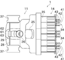
- FIG. 1 is a side view of a rice transplanter 1 used in the autonomous traveling system 100 according to an embodiment of the present invention.
- FIG. 2 is a plan view of the rice transplanter 1.
- FIG. 3 is a block diagram of the rice transplanter 1 and the wireless communication terminal 7.
- the autonomous traveling system 100 of the present embodiment is a system for causing the rice transplanter 1 for planting rice (planting seedlings) in the field to perform autonomous traveling.
- the autonomous traveling means that the device related to the traveling is controlled by the control device included in the rice transplanter 1, so that at least the steering is autonomously performed along a predetermined route. Further, in addition to steering, the vehicle speed or work by the working machine may be autonomously performed.
- the autonomous traveling includes a case where a person is on the rice transplanter 1 and a case where no person is on the rice transplanter 1.
- the work vehicle in the present invention is not limited to the rice transplanter 1, and may be, for example, a seeder, a tractor, a combine, or the like.
- the rice transplanter 1 includes a vehicle body portion 11, a front wheel 12, a rear wheel 13, and a planting portion 14.
- the front wheels 12 and the rear wheels 13 are provided in pairs with respect to the vehicle body portion 11, respectively.
- the vehicle body portion 11 is provided with a bonnet 21.
- the bonnet 21 is provided at the front portion of the vehicle body portion 11.
- An engine 22 is provided inside the bonnet 21.
- the power generated by the engine 22 is transmitted to the front wheels 12 and the rear wheels 13 via the mission case 23. This power is also transmitted to the planting portion 14 via the mission case 23 and the PTO shaft 24 arranged at the rear portion of the vehicle body portion 11.
- the vehicle body portion 11 further includes a driver's seat 25 for an operator to sit on, and a plurality of operating tools.
- the driver's seat 25 is arranged between the front wheels 12 and the rear wheels 13 in the front-rear direction of the vehicle body portion 11.
- the plurality of operating tools are, for example, a steering handle 26 and a speed change operation pedal 27.
- the direction of travel of the rice transplanter 1 is changed by operating the steering handle 26 by the operator.
- the speed change operation pedal 27 By operating the speed change operation pedal 27 by the operator, the traveling speed (vehicle speed) of the rice transplanter 1 is adjusted.
- the planting portion 14 is arranged behind the vehicle body portion 11.
- the planting portion 14 is connected to the vehicle body portion 11 via an elevating link mechanism 31.
- the elevating link mechanism 31 is composed of parallel links including a top link 31a and a lower link 31b.
- An elevating cylinder 32 is connected to the lower link 31b. As the elevating cylinder 32 expands and contracts, the planting portion 14 moves up and down with respect to the vehicle body portion 11.
- the elevating cylinder 32 is a hydraulic cylinder in this embodiment, it may be an electric cylinder.
- the planting unit 14 includes a planting input case unit 33, a plurality of planting units 34, a seedling stand 35, a plurality of floats 36, and a spare seedling stand 37.
- the planting unit 14 can sequentially supply seedlings from the seedling stand 35 to each planting unit 34 and continuously plant the seedlings.
- Each planting unit 34 has a planting transmission case portion 41 and a rotating case portion 42. Power is transmitted to the planting transmission case portion 41 via the PTO shaft 24 and the planting input case portion 33.
- the rotary case portion 42 is rotatably attached to the planting transmission case portion 41.
- the rotating case portions 42 are arranged on both sides of the planting transmission case portion 41 in the vehicle width direction.
- Two planting claws 43 are attached to one side of each rotating case portion 42.
- the two planting claws 43 are arranged in the traveling direction of the rice transplanter 1.
- the two planting claws 43 are displaced as the rotating case portion 42 rotates. By displacement of the two planting claws 43, one row of seedlings is planted.
- the seedling stand 35 is arranged in front of and above the plurality of planting units 34.
- the seedling mat can be placed on the seedling stand 35.
- the seedling stand 35 is configured so that the seedlings of the seedling mat placed on the seedling stand 35 can be supplied to each planting unit 34.
- the seedling stand 35 is configured to be laterally feedable (sliding in the lateral direction) so as to reciprocate in the vehicle width direction. Further, the seedling stand 35 is configured so that the seedling mat can be intermittently vertically fed downward at the reciprocating end of the seedling stand 35.
- the float 36 is swingably provided at the lower part of the planting portion 14.
- the float 36 can bring the lower surface of the float 36 into contact with the field surface in order to stabilize the planting posture of the planting portion 14 with respect to the field surface.
- the spare seedling stand 37 is provided in pairs with respect to the vehicle body portion 11.
- the spare seedling stand 37 is arranged outside the bonnet 21 in the vehicle width direction.
- the spare seedling stand 37 can be equipped with a seedling box containing spare mat seedlings.
- the upper parts of the pair of left and right spare seedling stands 37 are connected by a connecting frame 28 extending in the vertical direction and the vehicle width direction.
- a housing 29 is provided at the center of the connecting frame 28 in the vehicle width direction.
- a positioning antenna 61, an inertial measurement unit (IMU) 62, and a communication antenna 63 are provided inside the housing 29.
- the positioning antenna 61 can receive radio waves from the positioning satellites constituting the satellite positioning system (GNSS).
- GNSS satellite positioning system
- the position of the rice transplanter 1 can be acquired by performing a known positioning calculation based on this radio wave.
- the inertial measurement unit 62 has three gyro sensors (angular velocity sensors) and three acceleration sensors. The details of the information detected by the inertial measurement unit 62 and the initialization process of the inertial measurement unit 62 will be described later.
- the communication antenna 63 is an antenna for performing wireless communication with the wireless communication terminal 7 shown in FIG.
- the control unit 50 includes an arithmetic unit (not shown), a storage device, an input / output unit, and the like. Various programs, data, and the like are stored in the storage device. The arithmetic unit can read various programs from the storage device and execute them. By the cooperation of the hardware and software described above, the control unit 50 can be operated as the travel control unit 51, the work equipment control unit 52, the initialization control unit 53, and the condition setting unit 54.
- the control unit 50 may be one piece of hardware or a plurality of pieces of hardware that can communicate with each other. Further, in addition to the inertial measurement unit 62 described above, the control unit 50 is connected to a position acquisition unit 64, a communication processing unit 65, a vehicle speed sensor 66, and a steering angle sensor 67.
- the position acquisition unit 64 acquires the positioning information of the rice transplanter 1 as a mobile station based on the radio waves received by the positioning antenna 61 from the positioning satellite. More specifically, the position acquisition unit 64 acquires the pseudo distance from the positioning satellite to the positioning antenna 61 and the carrier phase when the radio wave reaches the positioning antenna 61 for each of the positioning satellites that have received the radio waves. .. This pseudo distance is obtained by multiplying the signal propagation time measured using the internal clock of the positioning satellite and the internal clock of the position acquisition unit 64 by the speed of light.
- the carrier wave phase is obtained by measuring the difference between the phase of the carrier wave received by the positioning antenna 61 and the phase output by the internal oscillator of the position acquisition unit 64.
- the position acquisition unit 64 acquires the positioning correction information generated based on the pseudo distance from the positioning satellite to the reference station 120 and the carrier phase when the reference station 120 is reached with respect to the reference station 120 whose position is known. To do. In the present embodiment, the position acquisition unit 64 acquires the positioning correction information by directly communicating between the reference station 120 and the rice transplanter 1. The position acquisition unit 64 may acquire positioning correction information via the Internet, a wireless communication terminal 7, or the like.
- the position acquisition unit 64 moves by performing a calculation by a known GNSS-RTK method using the positioning information which is the observed value obtained by the rice transplanter 1 and the positioning correction information generated by the reference station 120.
- the baseline solution between the rice transplanter 1 as a station and the reference station 120 is continuously calculated.
- the positioning solution which is the position of the rice transplanter 1
- both the rice transplanter 1 and the reference station 120 detect the carrier phase of the radio wave from the GNSS satellite and use it for the positioning calculation, so that the position of the rice transplanter 1 can be determined with significantly higher accuracy than the normal single positioning. Can be obtained.
- a positioning calculation using, for example, a differential GNSS may be performed.
- the communication processing unit 65 is electrically connected to the communication antenna 63.
- the communication processing unit 65 can perform modulation processing or demodulation processing by an appropriate method to transmit / receive data to / from the wireless communication terminal 7.
- the vehicle speed sensor 66 detects the vehicle speed of the rice transplanter 1.
- the vehicle speed sensor 66 is provided at an appropriate position of the rice transplanter 1, for example, on the axle of the front wheel 12. In this case, the vehicle speed sensor 66 generates a pulse according to the rotation of the axle of the front wheel 12.
- the detection result data obtained by the vehicle speed sensor 66 is output to the control unit 50.
- the steering angle sensor 67 detects the steering angle of the front wheels 12.
- the steering angle sensor 67 is provided at an appropriate position of the rice transplanter 1, for example, at a kingpin (not shown) provided on the front wheel 12.
- the steering angle sensor 67 may be provided on the steering handle 26.
- the detection result data obtained by the steering angle sensor 67 is output to the control unit 50.
- the travel control unit 51 automatically controls the travel of the rice transplanter 1.
- the travel control unit 51 can perform vehicle speed control and steering control.
- the travel control unit 51 may perform both vehicle speed control and steering control at the same time, or may perform only steering control. In the latter case, the vehicle speed of the rice transplanter 1 is operated by the operator using the speed change operation pedal 27.
- the vehicle speed of rice transplanter 1 is adjusted based on predetermined conditions. Specifically, the vehicle speed control is controlled by the traveling control unit 51 to bring the current vehicle speed obtained from the detection result of the vehicle speed sensor 66 closer to the target vehicle speed. This control is realized by changing at least one of the gear ratio of the transmission in the transmission case 23 and the rotation speed of the engine 22.
- the vehicle speed control also includes a control to set the vehicle speed to zero so that the rice transplanter 1 stops.
- Steering control is control that adjusts the rudder angle of the rice transplanter 1 based on predetermined conditions.
- the steering control unit 51 controls the current steering angle obtained from the detection result of the steering angle sensor 67 to approach the target steering angle. This control is realized, for example, by driving a steering actuator provided on the rotation shaft of the steering handle 26.
- the traveling control unit 51 may directly adjust the steering angle (wheel) of the front wheel 12 of the rice transplanter 1 instead of the rotation angle (steering angle) of the steering handle 26.
- the work machine control unit 52 can control the operation (elevation operation, planting work, etc.) of the planting unit 14 based on predetermined conditions.
- the processing performed by the initialization control unit 53 and the condition setting unit 54 will be described later.
- the wireless communication terminal 7 is a tablet terminal and includes a communication antenna 71, a communication processing unit 72, a display unit 73, an operation unit 74, a storage unit 75, and a calculation unit 80.
- the wireless communication terminal 7 is not limited to the tablet terminal, but may be a smartphone or a laptop computer.
- the wireless communication terminal 7 performs various processes related to the autonomous traveling of the rice transplanter 1, and the control unit 50 of the rice transplanter 1 may perform at least a part of these processes. On the contrary, the wireless communication terminal 7 may perform at least a part of various processes related to autonomous traveling performed by the control unit 50 of the rice transplanter 1.
- the communication antenna 71 is an antenna for short-range communication for wireless communication with the rice transplanter 1.
- the communication processing unit 72 is electrically connected to the communication antenna 71.
- the communication processing unit 72 performs modulation processing of the transmission signal, demodulation processing of the reception signal, and the like.
- either the rice transplanter 1 or the wireless communication terminal 7 is provided with a mobile phone line and a mobile communication antenna for performing communication using the Internet.
- a part of the information stored in the rice transplanter 1 or the wireless communication terminal 7 can be stored in an external server, or the information can be acquired from the external server.
- the display unit 73 is a liquid crystal display, an organic EL display, or the like, and is configured to be able to display an image.
- the display unit 73 can display, for example, information on autonomous driving, information on the setting of the rice transplanter 1, detection results of various sensors, warning information, and the like.
- the operation unit 74 includes a touch panel and a hardware key.
- the touch panel is arranged so as to overlap the display unit 73, and can detect an operation by an operator's finger or the like.
- the hardware key is arranged on the side surface of the housing of the wireless communication terminal 7 or around the display unit 73, and can be operated by being pressed by the operator.
- the wireless communication terminal 7 may be configured to include only one of a touch panel and a hardware key.
- the storage unit 75 is a non-volatile memory such as a flash memory or a hard disk.
- the storage unit 75 stores, for example, information about autonomous traveling.
- the arithmetic unit 80 is an arithmetic unit such as a CPU.
- the calculation unit 80 can read various programs from the storage unit 75 and execute them. By the cooperation of the above hardware and software, the calculation unit 80 can be operated as the display control unit 81 and the initialization instruction control unit 82. The processing performed by the display control unit 81 and the initialization instruction control unit 82 will be described later.
- the field includes a work area and a headland area.
- the work area is located in the central part of the field and is an area for performing work.
- the headland area is located outside the work area and is an area used for proper work in the work area.
- the headland area is used to move the rice transplanter 1 that has entered the field to the starting position of the work in the work area. Further, the headland area is also used as an area for turning the rice transplanter 1.
- the position and shape of the field are created based on the transition of the position information when the rice transplanter 1 is run along the outer circumference of the field.
- the position and shape of the field may be created by the user designating a range on a map displayed on the display unit 73 without actually running the rice transplanter 1.
- the information about the field is stored in the wireless communication terminal 7, but it may be stored in the server described above. In this case, the wireless communication terminal 7 acquires information about the field from this server.
- a traveling route 91 for autonomously traveling the rice transplanter 1 is created.
- the travel path 91 is created by, for example, the calculation unit 80.
- the traveling path 91 includes a plurality of straight paths 91a and a plurality of turning paths 91b. Further, a start position (S in FIG. 4) and an end position (G in FIG. 4) are set in the travel path 91.
- the traveling route 91 shown in FIG. 4 is an example, and the rice transplanter 1 can be autonomously traveled along a route having another feature.
- the inertial measurement unit 62 is a sensor unit capable of specifying the posture, acceleration, etc. of the rice transplanter 1. Specifically, the inertial measurement unit 62 includes a sensor group in which an angular velocity sensor and an acceleration sensor are attached to each of the first axis, the second axis, and the third axis that are orthogonal to each other.
- the inertial measurement unit 62 has a first acceleration sensor that detects the acceleration in the first axis direction, a second acceleration sensor that detects the acceleration in the second axis direction, and a second acceleration sensor that detects the acceleration in the third axis direction.
- a first angular velocity sensor that detects the angular velocity around the first axis
- a second angular velocity sensor that detects the angular velocity around the second axis
- a third angular velocity sensor that detects the angular velocity around the third axis.
- the first angular velocity sensor can detect the roll angular velocity of the rice transplanter 1
- the second angular velocity sensor can detect the pitch angular velocity of the rice transplanter 1
- the third angular velocity sensor can detect the yaw angular velocity of the rice transplanter 1.
- the direction is determined with respect to the machine 1, and it is attached to the position of the center of gravity of the rice transplanter 1.
- the first axis is arranged so as to coincide with the front-rear direction of the rice transplanter 1, that is, to be a roll rotation axis.
- the second axis is arranged so as to coincide with the left-right direction of the rice transplanter 1, that is, to be a pitch rotation axis.
- the third axis is arranged so as to coincide with the vertical direction of the rice transplanter 1, that is, to be the yaw rotation axis.
- the angular velocity (roll angular velocity, pitch angular velocity, and yaw angular velocity) of the attitude change of the rice planting machine 1 and the acceleration in the front-rear direction, the left-right direction, and the up-down direction can be specified. It has become like.
- the result of integrating the obtained angular velocities is used to acquire the posture of the rice transplanter 1.
- Information on the posture of the rice transplanter 1 is input to the control unit 50 and used for correcting the position information acquired by the position acquisition unit 64 or for other control.
- the position information is calculated by temporarily interrupting the radio waves from the GNSS satellite. If it becomes impossible, the position of the rice transplanter 1 in the meantime can be obtained.
- the angular velocity sensor of the inertial measurement unit 62 can detect the change in the orientation of the rice transplanter 1, but cannot detect the orientation itself of the rice transplanter 1. In particular, the angle (yaw angle) indicating which direction the rice transplanter 1 is facing cannot be obtained even if the gravitational acceleration is used as a clue.
- the rice transplanter 1 is actually moved straight in a predetermined direction (for example, forward or backward), and the position change of the rice transplanter 1 at this time is obtained by using GNSS radio waves, and the direction indicated by the position change is obtained.
- the yaw angle is calculated based on this.
- the process of determining the direction (yaw angle) at which the rice transplanter 1 faces in this way is called an initialization process, and the process of moving the rice transplanter 1 straight to perform the initialization process is called an initialization run.
- the vehicle speed and the mileage for performing the initialization running are predetermined.
- the initialization control unit 53 described above controls the initialization process.
- the condition setting unit 54 sets the conditions for starting the initialization process.
- the orientation detection unit may have a configuration different from that of the inertial measurement unit 62 of the present embodiment as long as it can detect at least the orientation of the rice transplanter 1 (specifically, the orientation with the vertical direction as the center of rotation). ..
- Patent Document 1 describes that the initialization process is performed only when the tractor is started. Further, Patent Document 1 describes that the operator manually performs the initialization running. Therefore, in the configuration of Patent Document 1, in order to perform the initialization process, it is necessary for the operator to board the tractor and turn on the power from off to on, and then the operator operates the tractor to perform the initialization traveling. In this respect, in the present embodiment, the operator can remotely instruct the initialization process without approaching the rice transplanter 1 while maintaining the power of the rice transplanter 1 turned on, and the initialization run is not performed manually. It can also be done autonomously. The details will be described below.
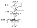
- the initialization process is performed when the rice transplanter 1 is started.
- the start-up time of the rice transplanter 1 indicates the time when the power supply of the rice transplanter 1 is switched from off to on (strictly speaking, until a predetermined time elapses after the rice transplanter 1 is switched on).
- the initialization control unit 53 determines whether or not the power supply of the rice transplanter 1 is switched from off to on (that is, whether or not it is immediately after the rice transplanter 1 is started). When the initialization control unit 53 determines that the power supply of the rice transplanter 1 has been switched from off to on, it determines whether or not GNSS-RTK positioning is effective (S102). GNSS-RTK positioning is effective when both the positioning information of the rice transplanter 1 as a mobile station and the positioning correction information generated by the reference station 120 are appropriately received and the calculation is performed by the GNSS-RTK method. Refers to the fact that Therefore, when GNSS-RTK positioning is effective, the position of the rice transplanter 1 can be acquired with high accuracy (predetermined accuracy).
- the position of the rice transplanter 1 cannot be acquired with high accuracy because GNSS-RTK is not effective.
- the position of the rice transplanter 1 can be acquired with low accuracy (less than a predetermined accuracy) by independent positioning.
- the initialization control unit 53 determines that the GNSS-RTK positioning is effective, the initialization control unit 53 performs the initialization process (S103). Specifically, the initialization control unit 53 instructs the travel control unit 51, and the travel control unit 51 sets the above-mentioned steering angle to neutral and advances the rice transplanter 1 straight (forward or backward) to perform initialization. I do. As described above, in the initialization running, the running control unit 51 can autonomously run the rice transplanter 1, but the operator may manually run the rice transplanter 1. Further, the initialization control unit 53 performs the initialization process of the inertial measurement unit 62 as described above during the initialization traveling. The value calculated in the initialization process is stored in the control unit 50 or the like and used for calculating the position and orientation of the rice transplanter 1.
- condition setting unit 54 sets that the power has been turned on from off as the first start condition of the initialization process. Further, in the present embodiment, it is also set that GNSS-RTK positioning is effective as another condition for starting the initialization process.
- the rice transplanter 1 may store the value calculated by the initialization process for a certain period of time even after the power is turned off. In this case, if it is clear that the orientation of the rice transplanter 1 has not changed while the power of the rice transplanter 1 is off (for example, when the rice transplanter 1 is restarted), the power of the rice transplanter 1 is turned off. Even when it is turned on, the value calculated in the previous initialization process may be used.
- the initialization control unit 53 determines whether or not the initialization process has been completed (S201). When the initialization process has been completed, it is not necessary to perform the initialization process, so the process related to autonomous driving (S206) is performed.
- the initialization control unit 53 determines whether or not GNSS-RTK positioning is effective, as in step S102 (S202). When the initialization control unit 53 determines that the GNSS-RTK positioning is effective, the initialization control unit 53 notifies the wireless communication terminal 7 to that effect. As a result, the display control unit 81 activates the initialization processing start button (S203).
- the initialization process start button is a button for the operator to instruct the start of the initialization process.
- the initialization process start button is a button on the GUI displayed on the display unit 73 of the wireless communication terminal 7.
- FIG. 7 shows a screen displayed on the display unit 73 of the wireless communication terminal 7 during preparation for autonomous traveling.
- a work vehicle icon 101 indicating the position of the rice transplanter 1 is displayed on a map showing a field to be autonomously traveled.
- a determination result button 102 indicating the determination result of the autonomous traveling condition and an autonomous traveling start button 103 for starting the autonomous traveling are further displayed.
- the determination result button 102 displays whether or not the autonomous driving condition is satisfied. In the example shown in FIG. 7, since the autonomous traveling condition is not satisfied, "NG" is displayed.
- the autonomous travel start button 103 is a button for instructing the start of autonomous travel. In the example shown in FIG. 7, since the autonomous traveling condition is not satisfied, the autonomous traveling start button 103 is invalid (grayed out). By operating the determination result button 102, the screen shown in FIG. 8 is displayed.
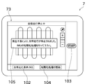
- the screen of FIG. 8 shows the autonomous driving conditions in detail.
- the autonomous driving conditions are that the steering angle is neutral, the position of the work vehicle matches the start position of the traveling path, and the initialization process of the inertial measurement unit 62 (IMU) is completed. That is included. If the initialization process is not completed, the initialization process start button 104 is displayed in the vicinity thereof.
- the display position, display hierarchy, and the like of the initialization process start button 104 are examples.
- the initialization process start button 104 may be displayed on the screen shown in FIG. 7.
- the initialization process start button 104 is normally hidden, and is displayed when it is enabled in step S203. Instead of this, it is usually displayed in gray out or the like, and may be operable when it is enabled in step S203. Further, in the present embodiment, the initialization process start button 104 is a button on the GUI, but may be a hardware key of the wireless communication terminal 7. Further, the initialization process start button 104 may be provided not on the wireless communication terminal 7 but on another terminal owned by the operator, or may be provided on the rice transplanter 1.
- a signal instructing the start of the initialization process is transmitted from the calculation unit 80 (initialization instruction control unit 82) to the control unit 50 (initialization control unit 53).
- the initialization control unit 53 determines whether or not the initialization process start button 104 has been operated based on the presence or absence of reception of this signal (S204).
- the initialization control unit 53 performs the initialization process in the same manner as in step S103 (S205).
- the initialization process can be performed without turning off the power of the rice transplanter 1, no restart time is required, so that the initialization process can be performed easily in a short time. be able to. Further, if there is a setting that is deleted by turning off the power of the rice transplanter 1, the trouble of such setting can be reduced.
- the autonomous travel system 100 may perform the initialization travel manually or autonomously. However, by autonomously performing the initialization running, the labor of the operator can be reduced. In particular, when the rice transplanter 1 is autonomously driven unmanned (without the operator boarding the driver's seat 25), the time and effort for the operator to move to the rice transplanter 1 for the initialization running can be reduced.
- the driving permission conditions include, for example, (1) that there are no obstacles in the area passed during the initialization driving, (2) that the start of the initialization driving is notified by a warning sound or the like, and (3) the operator is in the driver's seat 25.
- the condition (3) can be detected by the driver's seat 25 or a seat switch provided below the driver's seat 25.
- This travel permission condition is applied not only to the initialization travel performed when the power of the rice transplanter 1 is on, but also to the initialization travel performed when the power of the rice transplanter 1 is switched from off to on.
- the initialization process needs to be performed with the power of the rice transplanter 1 (control unit 50) turned on.
- the rice transplanter 1 and the wireless communication terminal 7 can communicate only when the power of the rice transplanter 1 is turned on. That is, even if the initialization process start button 104 is operated when the power of the rice transplanter 1 is off, the initialization process is not performed.
- the initialization process start button 104 may be enabled only when the power of the rice transplanter 1 is on.
- the IMU initialization condition among the autonomous driving conditions will be satisfied.
- the autonomous driving start button 103 is enabled (grayout is canceled). Then, when it is detected that the autonomous travel start button 103 has been operated, the travel control unit 51 starts autonomous travel (S206).
- condition setting unit 54 sets that, as the second start condition of the initialization process, it has received an instruction to perform the initialization process (received a signal) when the power of the rice transplanter 1 is on. doing. Further, in the present embodiment, it is also set that GNSS-RTK positioning is effective as another condition for starting the initialization process.
- FIG. 10 shows a screen displayed on the display unit 73 during autonomous driving.
- the position and traveling route of the rice transplanter 1 in the field are shown.
- the autonomous traveling stop button 105 is displayed instead of the place where the autonomous traveling start button 103 is displayed. By operating the autonomous travel stop button 105, autonomous travel is stopped.
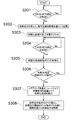
- the control unit 50 has detected whether or not GNSS-RTK positioning is effective (S301).
- positioning failure the fact that GNSS-RTK positioning is not effective is simply referred to as "positioning failure" or the like. As described above, when a positioning failure occurs, the position of the rice transplanter 1 cannot be acquired with high accuracy.
- the travel control unit 51 stops autonomous travel and stores the current position as a restart position (S302).
- the restart position is a position for restarting autonomous driving. That is, since the rice transplanter 1 moves by performing the initialization run, there is an area where the work is not performed. In order to prevent this, the autonomous traveling system 100 is configured to restart the autonomous traveling after returning the rice transplanter 1 to the restarting position.
- the initialization control unit 53 resets the completion state of this initialization process (S303). As a result, the set value obtained in the previously performed initialization process is deleted. Further, until a new initialization process is performed, the restart of the autonomous traveling of the rice transplanter 1 along the traveling route 91 is prohibited.
- the display control unit 81 of the wireless communication terminal 7 displays a message to that effect on the display unit 73 (see FIG. 11). This message may include that initialization processing is required, as shown in FIG. Further, the display control unit 81 displays the initialization process start button 104 on the display unit 73. As shown in FIG. 11, the initialization process start button 104 is not activated until the positioning defect is resolved.
- the display control unit 81 activates the initialization process start button 104 by canceling the grayout of the initialization process start button 104 (S305). Further, when the initialization process start button 104 is operated (S306), the initialization instruction control unit 82 transmits a signal instructing the start of the initialization process to the control unit 50. When the initialization control unit 53 determines that this signal has been received, the initialization control unit 53 performs the initialization run and initializes the inertial measurement unit 62 (S307) in the same manner as in step S205. The points regarding the travel permission conditions are the same as those in step S205.
- the traveling control unit 51 autonomously moves the rice transplanter 1 to the restart position and starts autonomous traveling from the restart position (S308). ).
- the second start condition of the initialization process is the same both during the preparation for autonomous driving and when the autonomous driving is stopped.
- the autonomous travel system 100 of the present embodiment includes a position acquisition unit 64, an inertial measurement unit 62, a travel control unit 51, an initialization control unit 53, and a condition setting unit 54. ..
- the position acquisition unit 64 acquires the position of the rice transplanter 1 using a satellite positioning system.
- the inertial measurement unit 62 detects the orientation of the rice transplanter 1.
- the travel control unit 51 autonomously causes the rice transplanter 1 to travel along a preset travel path 91.
- the initialization control unit 53 obtains the direction of the rice transplanter 1 based on the acquired value of the position acquisition unit 64 while the rice transplanter 1 is performing the initialization traveling straight in a predetermined direction, so that the inertial measurement unit 62 Initialization process of.
- the condition setting unit 54 is set that the power supply of the rice transplanter 1 is switched from off to on as the first start condition of the initialization process, and the power supply of the rice transplanter 1 is set as the second start condition of the initialization process. It is set that an instruction to perform initialization processing is accepted when it is on.
- the initialization process can be performed by giving a separate instruction. it can. Therefore, since the initialization process can be performed without turning off the power of the rice transplanter 1, the initialization process of the inertial measurement unit 62 can be easily performed.
- the rice transplanter 1 is autonomously initialized and run.
- the rice transplanter 1 can be autonomously driven to perform the initialization process, so that the operator's labor can be reduced as compared with the case where the operator manually drives the rice transplanter 1.
- the travel control unit 51 stops autonomous travel along the travel route when the position acquisition unit 64 cannot acquire the position of the rice transplanter 1 with a predetermined accuracy. ..
- the initialization control unit 53 resets the initialization completion state when the position acquisition unit 64 cannot acquire the position of the rice transplanter 1 with a predetermined accuracy.
- the travel control unit 51 satisfies the first start condition or the second start condition, and the travel permission condition is satisfied, the rice transplanter 51 can plant the rice.
- the machine 1 is autonomously initialized and run.
- the rice transplanter 1 can be autonomously driven to perform initialization processing, so that the operator's labor can be reduced.
- the traveling control unit 51 sets a position at which the position acquisition unit 64 cannot acquire the position of the rice transplanter 1 with a predetermined accuracy and stops the autonomous traveling as a restart position. After the initialization process is completed, the rice transplanter 1 is autonomously driven to the restart position.
- an instruction to perform initialization processing is transmitted from a wireless communication terminal 7 provided separately from the rice transplanter 1.
- the flowchart shown in the above embodiment is an example, and some processes may be omitted, the contents of some processes may be changed, or new processes may be added. For example, when the initialization running is performed autonomously, a process for displaying the fact on the display unit 73 may be added. Further, after the initialization process start button is operated, it may be determined again whether or not GNSS-RTK positioning is effective.
- the initialization process start button 104 may be enabled when the travel permission condition is satisfied.
- the completed state of the previous initialization process is automatically reset when the positioning is defective, but the completed state may be reset in response to an operator's instruction.
- the button for instructing the reset of the previous initialization process and the button for instructing the start of the new initialization process may be separated.
- the configuration may be such that these two processes are performed by operating one button.
Landscapes
- Engineering & Computer Science (AREA)
- Life Sciences & Earth Sciences (AREA)
- Remote Sensing (AREA)
- Radar, Positioning & Navigation (AREA)
- Soil Sciences (AREA)
- Environmental Sciences (AREA)
- Physics & Mathematics (AREA)
- Aviation & Aerospace Engineering (AREA)
- General Physics & Mathematics (AREA)
- Automation & Control Theory (AREA)
- Mechanical Engineering (AREA)
- Business, Economics & Management (AREA)
- Health & Medical Sciences (AREA)
- Artificial Intelligence (AREA)
- Evolutionary Computation (AREA)
- Game Theory and Decision Science (AREA)
- Medical Informatics (AREA)
- Guiding Agricultural Machines (AREA)
- Control Of Position, Course, Altitude, Or Attitude Of Moving Bodies (AREA)
Abstract
Le présent système de déplacement autonome est pourvu d'une unité d'acquisition d'emplacement, d'un dispositif de mesure d'inertie, d'une unité de commande de déplacement, d'une unité de commande d'initialisation et d'une unité de réglage de condition. L'unité d'acquisition d'emplacement acquiert un emplacement du véhicule de travail à l'aide d'un système de positionnement par satellites. Le dispositif de mesure d'inertie détecte une orientation du véhicule de travail. L'unité de commande de déplacement amène le véhicule de travail à se déplacer de manière autonome le long d'un trajet de déplacement prédéterminé. L'unité de commande d'initialisation réalise un processus d'initialisation pour le dispositif de mesure d'inertie par l'obtention de l'orientation du véhicule de travail sur la base d'une valeur acquise par l'unité d'acquisition d'emplacement pendant le déplacement d'initialisation dans lequel le véhicule de travail se déplace en ligne droite dans une direction prédéterminée. Dans l'unité de réglage de condition, une commutation de l'état d'arrêt à l'état de marche d'une source d'alimentation du véhicule de travail est définie comme étant une première condition de démarrage pour le processus d'initialisation, et l'acceptation d'une instruction pour effectuer le processus d'initialisation lorsque la source d'alimentation du véhicule de travail est en état de marche est définie comme étant une seconde condition de démarrage pour le processus d'initialisation.
Priority Applications (4)
| Application Number | Priority Date | Filing Date | Title |
|---|---|---|---|
| CN202080036154.XA CN113825390A (zh) | 2019-05-17 | 2020-03-25 | 自主行驶系统 |
| EP20809034.0A EP3970462A4 (fr) | 2019-05-17 | 2020-03-25 | Système de déplacement autonome |
| US17/611,887 US20220217893A1 (en) | 2019-05-17 | 2020-03-25 | Autonomous Travel System |
| KR1020217033933A KR20220010474A (ko) | 2019-05-17 | 2020-03-25 | 자율 주행 시스템 |
Applications Claiming Priority (2)
| Application Number | Priority Date | Filing Date | Title |
|---|---|---|---|
| JP2019-093355 | 2019-05-17 | ||
| JP2019093355A JP7227070B2 (ja) | 2019-05-17 | 2019-05-17 | 自律走行システム |
Publications (1)
| Publication Number | Publication Date |
|---|---|
| WO2020235209A1 true WO2020235209A1 (fr) | 2020-11-26 |
Family
ID=73222264
Family Applications (1)
| Application Number | Title | Priority Date | Filing Date |
|---|---|---|---|
| PCT/JP2020/013193 WO2020235209A1 (fr) | 2019-05-17 | 2020-03-25 | Système de déplacement autonome |
Country Status (6)
| Country | Link |
|---|---|
| US (1) | US20220217893A1 (fr) |
| EP (1) | EP3970462A4 (fr) |
| JP (1) | JP7227070B2 (fr) |
| KR (1) | KR20220010474A (fr) |
| CN (1) | CN113825390A (fr) |
| WO (1) | WO2020235209A1 (fr) |
Families Citing this family (3)
| Publication number | Priority date | Publication date | Assignee | Title |
|---|---|---|---|---|
| JP2022183958A (ja) * | 2021-05-31 | 2022-12-13 | ヤンマーホールディングス株式会社 | 自動走行方法、自動走行システム、及び自動走行プログラム |
| JP2023150416A (ja) * | 2022-03-31 | 2023-10-16 | ヤンマーホールディングス株式会社 | 自動走行方法、自動走行システム、及び自動走行プログラム |
| CN114947627B (zh) * | 2022-08-01 | 2022-11-22 | 深圳市云鼠科技开发有限公司 | 扫地机imu初始化的判定方法、装置、设备及存储介质 |
Citations (6)
| Publication number | Priority date | Publication date | Assignee | Title |
|---|---|---|---|---|
| JPH09304079A (ja) * | 1996-05-15 | 1997-11-28 | Fuji Heavy Ind Ltd | 自律走行車の走行制御装置 |
| JP2000172337A (ja) * | 1998-12-07 | 2000-06-23 | Mitsubishi Electric Corp | 自律移動ロボット |
| US7400956B1 (en) * | 2003-03-20 | 2008-07-15 | Hemisphere Gps Inc. | Satellite position and heading sensor for vehicle steering control |
| JP2017199107A (ja) * | 2016-04-26 | 2017-11-02 | ヤンマー株式会社 | 作業車両制御システム |
| JP2018163507A (ja) | 2017-03-24 | 2018-10-18 | ヤンマー株式会社 | 自律走行システム |
| JP2019041590A (ja) * | 2017-08-29 | 2019-03-22 | 井関農機株式会社 | 作業車両 |
Family Cites Families (5)
| Publication number | Priority date | Publication date | Assignee | Title |
|---|---|---|---|---|
| JPH07147804A (ja) * | 1993-12-02 | 1995-06-13 | Fuji Heavy Ind Ltd | 自律走行作業車の作業領域逸脱防止装置 |
| JP2005215742A (ja) | 2004-01-27 | 2005-08-11 | Yanmar Co Ltd | 農業用作業車 |
| US10136576B2 (en) * | 2013-11-12 | 2018-11-27 | Husqvarna Ab | Navigation for a robotic working tool |
| CN107407733B (zh) * | 2015-10-30 | 2020-08-11 | 株式会社小松制作所 | 作业机械的控制系统、作业机械、作业机械的管理系统以及作业机械的管理方法 |
| JP7019310B2 (ja) | 2017-05-29 | 2022-02-15 | ヤンマーパワーテクノロジー株式会社 | 自律走行システム |
-
2019
- 2019-05-17 JP JP2019093355A patent/JP7227070B2/ja active Active
-
2020
- 2020-03-25 EP EP20809034.0A patent/EP3970462A4/fr active Pending
- 2020-03-25 KR KR1020217033933A patent/KR20220010474A/ko unknown
- 2020-03-25 CN CN202080036154.XA patent/CN113825390A/zh active Pending
- 2020-03-25 WO PCT/JP2020/013193 patent/WO2020235209A1/fr active Application Filing
- 2020-03-25 US US17/611,887 patent/US20220217893A1/en active Pending
Patent Citations (6)
| Publication number | Priority date | Publication date | Assignee | Title |
|---|---|---|---|---|
| JPH09304079A (ja) * | 1996-05-15 | 1997-11-28 | Fuji Heavy Ind Ltd | 自律走行車の走行制御装置 |
| JP2000172337A (ja) * | 1998-12-07 | 2000-06-23 | Mitsubishi Electric Corp | 自律移動ロボット |
| US7400956B1 (en) * | 2003-03-20 | 2008-07-15 | Hemisphere Gps Inc. | Satellite position and heading sensor for vehicle steering control |
| JP2017199107A (ja) * | 2016-04-26 | 2017-11-02 | ヤンマー株式会社 | 作業車両制御システム |
| JP2018163507A (ja) | 2017-03-24 | 2018-10-18 | ヤンマー株式会社 | 自律走行システム |
| JP2019041590A (ja) * | 2017-08-29 | 2019-03-22 | 井関農機株式会社 | 作業車両 |
Non-Patent Citations (1)
| Title |
|---|
| See also references of EP3970462A4 |
Also Published As
| Publication number | Publication date |
|---|---|
| CN113825390A (zh) | 2021-12-21 |
| JP7227070B2 (ja) | 2023-02-21 |
| JP2020187669A (ja) | 2020-11-19 |
| EP3970462A1 (fr) | 2022-03-23 |
| US20220217893A1 (en) | 2022-07-14 |
| KR20220010474A (ko) | 2022-01-25 |
| EP3970462A4 (fr) | 2023-06-07 |
Similar Documents
| Publication | Publication Date | Title |
|---|---|---|
| JP7354217B2 (ja) | 自動作業システム | |
| WO2020235209A1 (fr) | Système de déplacement autonome | |
| JP6643091B2 (ja) | 農作業機 | |
| KR102192966B1 (ko) | 조작 단말 | |
| JP6267626B2 (ja) | 走行経路設定装置 | |
| JP6594805B2 (ja) | 作業車両 | |
| JP6267627B2 (ja) | 操作端末 | |
| JP6253565B2 (ja) | 操作端末 | |
| KR20200092435A (ko) | 병주 작업 시스템 | |
| JP6267586B2 (ja) | ディスプレイ装置 | |
| JP6850759B2 (ja) | 自律操舵装置 | |
| JP2019170197A (ja) | 領域登録システム | |
| JP2022169575A (ja) | 走行作業機 | |
| JP6258782B2 (ja) | モニタ装置 | |
| WO2020240982A1 (fr) | Système de déplacement autonome | |
| JP6921934B2 (ja) | 農作業機 | |
| JP7045979B2 (ja) | 走行作業機 | |
| JP7140858B2 (ja) | 走行経路生成方法、走行経路生成システム | |
| JP6832996B2 (ja) | 走行経路生成方法 | |
| US20220147046A1 (en) | Autonomous Traveling System | |
| JP2021175405A (ja) | 農作業機 | |
| JP2019135670A (ja) | 作業車両の走行領域登録システム | |
| JP6934510B2 (ja) | 農作業機 | |
| US20220159899A1 (en) | Autonomous travel system |
Legal Events
| Date | Code | Title | Description |
|---|---|---|---|
| 121 | Ep: the epo has been informed by wipo that ep was designated in this application |
Ref document number: 20809034 Country of ref document: EP Kind code of ref document: A1 |
|
| NENP | Non-entry into the national phase |
Ref country code: DE |
|
| WWE | Wipo information: entry into national phase |
Ref document number: 2020809034 Country of ref document: EP |