WO2020235053A1 - 冷蔵庫 - Google Patents
冷蔵庫 Download PDFInfo
- Publication number
- WO2020235053A1 WO2020235053A1 PCT/JP2019/020301 JP2019020301W WO2020235053A1 WO 2020235053 A1 WO2020235053 A1 WO 2020235053A1 JP 2019020301 W JP2019020301 W JP 2019020301W WO 2020235053 A1 WO2020235053 A1 WO 2020235053A1
- Authority
- WO
- WIPO (PCT)
- Prior art keywords
- oil separator
- condenser
- compressor
- refrigerator
- refrigerant
- Prior art date
Links
- 239000003507 refrigerant Substances 0.000 claims abstract description 126
- 238000011144 upstream manufacturing Methods 0.000 claims abstract description 33
- 239000003921 oil Substances 0.000 claims description 162
- 239000010721 machine oil Substances 0.000 claims description 9
- 239000012071 phase Substances 0.000 description 22
- 239000010687 lubricating oil Substances 0.000 description 15
- 239000012808 vapor phase Substances 0.000 description 14
- 238000000926 separation method Methods 0.000 description 6
- 230000006835 compression Effects 0.000 description 5
- 238000007906 compression Methods 0.000 description 5
- 239000007788 liquid Substances 0.000 description 5
- 239000007791 liquid phase Substances 0.000 description 5
- 238000000034 method Methods 0.000 description 5
- 230000005494 condensation Effects 0.000 description 4
- 238000009833 condensation Methods 0.000 description 4
- 230000007423 decrease Effects 0.000 description 4
- 238000001816 cooling Methods 0.000 description 3
- 230000000694 effects Effects 0.000 description 3
- 239000012530 fluid Substances 0.000 description 2
- 238000009423 ventilation Methods 0.000 description 2
- 238000010276 construction Methods 0.000 description 1
- 238000007599 discharging Methods 0.000 description 1
- 238000009413 insulation Methods 0.000 description 1
- 238000012986 modification Methods 0.000 description 1
- 230000004048 modification Effects 0.000 description 1
Images


Classifications
-
- F—MECHANICAL ENGINEERING; LIGHTING; HEATING; WEAPONS; BLASTING
- F25—REFRIGERATION OR COOLING; COMBINED HEATING AND REFRIGERATION SYSTEMS; HEAT PUMP SYSTEMS; MANUFACTURE OR STORAGE OF ICE; LIQUEFACTION SOLIDIFICATION OF GASES
- F25B—REFRIGERATION MACHINES, PLANTS OR SYSTEMS; COMBINED HEATING AND REFRIGERATION SYSTEMS; HEAT PUMP SYSTEMS
- F25B1/00—Compression machines, plants or systems with non-reversible cycle
-
- F—MECHANICAL ENGINEERING; LIGHTING; HEATING; WEAPONS; BLASTING
- F25—REFRIGERATION OR COOLING; COMBINED HEATING AND REFRIGERATION SYSTEMS; HEAT PUMP SYSTEMS; MANUFACTURE OR STORAGE OF ICE; LIQUEFACTION SOLIDIFICATION OF GASES
- F25B—REFRIGERATION MACHINES, PLANTS OR SYSTEMS; COMBINED HEATING AND REFRIGERATION SYSTEMS; HEAT PUMP SYSTEMS
- F25B43/00—Arrangements for separating or purifying gases or liquids; Arrangements for vaporising the residuum of liquid refrigerant, e.g. by heat
- F25B43/02—Arrangements for separating or purifying gases or liquids; Arrangements for vaporising the residuum of liquid refrigerant, e.g. by heat for separating lubricants from the refrigerant
-
- F—MECHANICAL ENGINEERING; LIGHTING; HEATING; WEAPONS; BLASTING
- F25—REFRIGERATION OR COOLING; COMBINED HEATING AND REFRIGERATION SYSTEMS; HEAT PUMP SYSTEMS; MANUFACTURE OR STORAGE OF ICE; LIQUEFACTION SOLIDIFICATION OF GASES
- F25D—REFRIGERATORS; COLD ROOMS; ICE-BOXES; COOLING OR FREEZING APPARATUS NOT OTHERWISE PROVIDED FOR
- F25D19/00—Arrangement or mounting of refrigeration units with respect to devices or objects to be refrigerated, e.g. infrared detectors
Definitions
- the present invention relates to a refrigerator.
- the compression part for compressing the refrigerant is generally lubricated with lubricating oil.
- a part of the lubricating oil is discharged to the refrigerant circuit together with the refrigerant compressed by the compression unit.
- the pressure loss of the fluid flowing through the refrigerant circuit becomes larger, the heat transfer property of the fluid decreases, and the cooling capacity of the refrigerator decreases, as compared with the case where only the refrigerant flows through the refrigerant circuit.
- Patent No. 3485006 describes a refrigerant circuit including a compressor, a condenser, a throttle device, an evaporator as a cooler, and an oil separator, and a return passage connected to the refrigerant circuit and including a solenoid valve.
- a refrigerator equipped with is disclosed. In the refrigerator, an oil separator is arranged between the compressor and the condenser so as to separate the lubricating oil from the refrigerant discharged from the compressor.
- Japanese Patent No. 3485006 does not disclose the relative positional relationship of each component constituting the refrigerant circuit in the flow path of the gas that exchanges heat with the refrigerant.
- the relative positional relationship between the compressor, the condenser, and the oil separator in the gas flow path is not disclosed.
- the condensing capacity of the refrigerator changes according to the relative positional relationship between the parts constituting the refrigerant circuit in the flow of the gas that exchanges heat with the refrigerant flowing through the refrigerant circuit. This is because when the relative positional relationship between the parts in the gas flow is changed, the temperature of the gas flowing around each part also changes, and as a result, the state of the refrigerant flowing through each part also changes.
- a main object of the present invention is to provide a refrigerator equipped with an oil separator and having a high condensing capacity.
- the refrigerator according to the present invention includes a compressor, an oil separator, a condenser, a throttle device, and an evaporator, and a refrigerant circuit in which a refrigerant circulates in this order through the compressor, an oil separator, a condenser, a throttle device, and an evaporator.
- the compressor includes an inlet and an outlet and is lubricated with refrigerating machine oil.
- the oil separator is provided so as to separate the refrigerant discharged from the discharge port and the refrigerating machine oil.
- the condenser is provided so that the refrigerant flowing through the condenser and the gas flowing along the first direction exchange heat with each other. In the first direction, the oil separator is located upstream of the compressor.
- FIG. It is a figure which shows the refrigerant circuit and the oil return passage of the refrigerator which concerns on Embodiment 1.
- FIG. It is a figure which shows the machine room and the heat insulating part of the refrigerator shown in FIG. It is a figure which shows the arrangement example of the oil separator of the refrigerator shown in FIG. It is a figure which shows the arrangement example of the oil separator of the refrigerator which concerns on Embodiment 2.
- FIG. 3 shows the arrangement example of the oil separator of the refrigerator which concerns on Embodiment 3.
- the refrigerator 100 includes a refrigerant circuit constituting a refrigerating cycle and an oil return passage connected to the refrigerant circuit.
- the refrigerant circuit includes a compressor 1, a condenser 2, a first throttle device 3, an evaporator 4, and an oil separator 5.
- the refrigerant circuit is provided so that the refrigerant circulates in order through the compressor 1, the oil separator 5, the condenser 2, the first throttle device 3, and the evaporator 4.
- the compressor 1 includes a suction port for sucking the refrigerant, a compression unit for compressing the refrigerant sucked from the suction port, and a discharge port for discharging the high-temperature and high-pressure vapor-phase refrigerant compressed by the compression unit.
- the compressed portion is lubricated with refrigerating machine oil (hereinafter referred to as oil).
- the compression unit is housed in the shell 10.
- the suction port and the discharge port are provided as openings on the shell 10.
- the compressor 1 discharges the refrigerant and the refrigerating machine oil from the discharge port. Further, the compressor 1 sucks the refrigerant and the oil from the suction port.
- the discharge port of the compressor 1 is connected to the inflow port of the oil separator 5 via the first flow path 11.
- the suction port of the compressor 1 is connected to the outlet of the evaporator 4 via the second flow path 12 and the third flow path 13. Further, the suction port of the compressor 1 is connected to the oil return passage 14 via the third flow path 13.
- the oil separator 5 includes an inflow port into which the gas phase refrigerant and oil flow in, a first outflow port from which the gas phase refrigerant flows out, and a second outflow port from which oil flows out.
- the oil separator 5 is provided so as to separate the vapor phase refrigerant and oil flowing in from the inflow port into the gas phase refrigerant and the oil, and to discharge each of them from the first outlet or the second outlet.
- the first outlet of the oil separator 5 is connected to the inlet of the condenser 2.
- the condenser 2 includes an inflow port into which the gas phase refrigerant flowing out from the first outflow port of the oil separator 5 flows in, and an outflow port in which the liquid phase refrigerant flows out.
- the condenser 2 is provided so that the gas phase refrigerant flowing in from the inflow port exchanges heat with the gas flowing along the first direction A (see FIG. 2). As a result, the gas phase refrigerant is condensed into a liquid phase refrigerant.
- the outlet of the condenser 2 is connected to the inlet of the first throttle device 3.
- the flow of gas along the first direction A is formed around the condenser 2 by the blower 8.
- the first throttle device 3 includes an inflow port into which the liquid phase refrigerant condensed in the condenser 2 flows in and an outflow port into which the gas-liquid 2 refrigerant flows out.
- the first throttle device 3 is provided so as to reduce the pressure of the liquid phase refrigerant flowing in from the inflow port. As a result, the liquid-phase refrigerant expands to become a gas-liquid two-phase refrigerant.
- the first drawing device 3 is provided as, for example, a capillary tube.
- the evaporator 4 includes an inflow port into which the gas-liquid two-phase refrigerant decompressed in the first throttle device 3 flows in, and an outflow port from which the gas-phase refrigerant flows out.
- the evaporator 4 is provided so that the gas-liquid two-phase refrigerant flowing in from the inflow port exchanges heat with the air in the storage chamber of the refrigerator 100. As a result, the gas-liquid two-phase refrigerant evaporates to become a gas-phase refrigerant.
- the outlet of the evaporator 4 is connected to the suction port of the compressor 1 via the second flow path 12 and the third flow path 13. Further, the outlet of the evaporator 4 is connected to the oil return passage 14 via the second flow path 12.
- the second flow path 12 and the third flow path 13 connect the outlet of the evaporator 4 and the suction port of the compressor 1.
- One end of the second flow path 12 in the flow direction of the refrigerant is connected to the outlet of the evaporator 4.
- the other end of the second flow path 12 in the distribution direction is connected to one end of the third flow path 13.
- the other end of the third flow path 13 is connected to the suction port of the compressor 1.
- the other end of the second flow path 12 and the other end of the third flow path 13 are connected to the oil return passage 14.
- the refrigerator 100 does not have an on-off valve that opens and closes the second flow path 12.
- the oil return passage 14 is connected to the first end connected to the second outlet of the oil separator 5, the other end of the second flow path 12, and the first end of the third flow path 13. It has two ends.
- the second end of the oil return passage 14 is connected to a connecting portion 18 between the other end of the second flow path 12 and the one end of the third flow path 13.
- the oil return passage 14 bypasses the condenser 2, the first throttle device 3, and the evaporator 4 in the refrigerant circuit, and connects the second outlet of the oil separator 5 and the suction port of the compressor 1. There is.
- the oil return passage 14 is provided so as to return the oil separated from the refrigerant by the oil separator 5 to the suction port of the compressor 1.
- the oil return passage 14 includes an on-off valve 6 and a second throttle device 7.
- the on-off valve 6 is provided so as to open and close the oil return passage 14.
- the second throttle device 7 is provided so as to reduce the pressure of the oil flowing through the oil return passage 14.
- the on-off valve 6 is, for example, a solenoid valve.
- the on-off valve 6 is controlled so as to close the oil return passage 14 when the compressor 1 is driven and open the oil return passage 14 when the compressor 1 is stopped.
- the second drawing device 7 is, for example, a capillary tube.
- the refrigerator 100 includes a machine room 21 and a heat insulating portion 22.
- the machine room 21 includes, for example, a compressor 1, a first throttle device 3, an oil separator 5, an on-off valve 6, a second throttle device 7, a first flow path 11, a part of a second flow path 12, and a third flow path. 13, the oil return passage 14, and the blower 8 are housed inside.
- the heat insulating portion 22 houses, for example, the remainder of the evaporator 4 and the fifth flow path 15 inside.
- the heat insulating portion 22 is provided so as to surround a storage chamber (not shown) cooled by the evaporator 4.
- the heat insulating portion 22 has a portion arranged above the machine room 21.
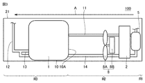
- the machine room 21 of the refrigerator 100 houses a compressor 1, a condenser 2, an oil separator 5, and a blower 8.
- the first direction A shown in FIG. 3 is along the horizontal direction.
- the first direction A is the flow direction of the gas flowing around the condenser 2 by the blower 8 as described above. Ventilation ports (not shown) are provided at both ends of the machine room 21 in the first direction A.
- the compressor 1, the condenser 2, the oil separator 5, and the blower 8 are arranged side by side between the two ventilation ports in the first direction A.
- FIG. 3 in the refrigerant circuit shown in FIG. 1, the illustration of other flow paths other than the first flow path 11, the second flow path 12, and the third flow path 13 is omitted.
- the condenser 2 is arranged on the upstream side of the compressor 1 in the first direction A.
- the blower 8 is arranged on the upstream side of the compressor 1 and on the downstream side of the condenser 2 in the first direction A.
- the oil separator 5 is arranged above the condenser 2. That is, the oil separator 5, the condenser 2, the blower 8, and the compressor 1 are arranged side by side in order from the upstream side to the downstream side in the first direction A.
- At least a part of the first flow path 11 and the oil return path 14 is arranged on the upstream side of the compressor 1 in the first direction A.
- the first flow path 11 and the oil return passage 14 are passed beside the condenser 2 and the blower 8 in a direction perpendicular to the first direction A.
- the first flow path 11 and the oil return passage 14 are provided so as to extend along the first direction A, for example.
- the blower 8 includes, for example, an impeller 8A and a drive unit 8B for driving the impeller 8A.
- the impeller 8A and the drive unit 8B are arranged side by side in the first direction A.
- the impeller 8A is arranged, for example, in the first direction A on the downstream side of the drive unit 8B.
- the condenser 2, the oil separator 5, and the blower 8 are arranged so that at least a part of each overlaps.
- the compressor 1, the condenser 2, the oil separator 5, and the blower 8 are arranged so that at least a part of each overlaps.
- the refrigerator 100 has a first state in which the compressor 1 is driven and the refrigerant circulates in the refrigerant circuit, and a second state in which the compressor 1 is stopped and the refrigerant does not circulate in the refrigerant circuit. It is provided to switch between states.
- the oil return passage 14 is closed by the on-off valve 6 in the first state and opened by the on-off valve 6 in the second state.
- the refrigerant is the compressor 1, the first flow path 11, the oil separator 5, the condenser 2, the first throttle device 3, the evaporator 4, the second flow path 12, and the third flow path 13. Is circulated in order.
- the refrigerator 100 can cool the air in the storage chamber.
- the pressure difference between the first flow path 11 and the third flow path 13, that is, the pressure difference applied between both ends of the oil return passage 14, is the oil separator. Acts on the oil separated in 5. After the second state is realized, the oil separated in the oil separator 5 in the first state flows through the oil return passage 14 due to the pressure difference and is returned to the third flow path 13.
- At least three temperature regions of a first temperature region R1, a second temperature region R2, and a third temperature region R3 are formed in the machine room 21 shown in FIG. To.
- the first temperature region R1 is a region located on the most upstream side of the machine room 21 in the first direction A, and is a region located on the upstream side of the oil separator 5 in the first direction A.
- the temperature of the atmosphere in the first temperature region R1 is equal to or higher than the outside air temperature Tatm and lower than the condensation temperature Tc.
- the second temperature region R2 is a region located downstream of the first temperature region R1 and upstream of the third temperature region R3 in the first direction A.
- the second temperature region R2 is a region located downstream of the oil separator 5 and upstream of the compressor 1 in the first direction A, more specifically, the surface of the shell 10 of the compressor 1. It is a region located on the upstream side of 10A.
- a part of each of the condenser 2, the oil separator 5, the first flow path 11, and the second flow path 12 and the third flow path 13 is arranged in the second temperature region R2.
- the air flowing from the first temperature region R1 to the second temperature region R2 is heated by exchanging heat with the refrigerant discharged from the compressor 1 in the oil separator 5 and the condenser 2.
- the refrigerant discharged from the compressor 1 is condensed by the heat exchange.
- the temperature of the atmosphere in the second temperature region R2 becomes higher than the temperature of the atmosphere in the first temperature region R1, the condensation temperature Tc or more, and the refrigerant temperature Td discharged from the compressor 1 or less.
- the temperature of the atmosphere in the second temperature region R2 increases from the upstream side to the downstream side in the first direction A. Since the air heat-exchanged with the refrigerant in the oil separator 5 flows around the condenser 2, the temperature around the condenser 2 is higher than the temperature around the oil separator 5.
- the refrigerant discharged from the compressor 1 and flowing into the oil separator 5 has an outside air temperature of Tatm or more and a condensation temperature of less than Tc. It exchanges heat with air and condenses.
- the third temperature region R3 is a region located on the downstream side of the second temperature region R2 in the first direction A.
- the third temperature region R3 includes a region located around the compressor 1 in the direction perpendicular to the first direction A and a region located downstream of the compressor 1 in the first direction A.
- the compressor 1 that acts as a heat source in the refrigerant circuit is arranged in the third temperature region R3. Further, the remaining portions of the second flow path 12 and the third flow path 13 are arranged in the third temperature region R3. The air flowing from the second temperature region R2 to the third temperature region R3 is heated by the shell 10 of the compressor 1.
- the temperature of the atmosphere in the third temperature region R3 is higher than the temperature of the atmosphere in the second temperature region R2, for example, higher than the condensation temperature Tc and lower than the refrigerant temperature Td discharged from the compressor 1.
- the temperature of the air in the third temperature region R3 is, for example, about 10 ° C. or more higher than the temperature of the air in the first temperature region R1.
- the refrigerator 100 includes a compressor 1, an oil separator 5, a condenser 2, a first throttle device 3, and an evaporator 4, and the refrigerant is a compressor 1, an oil separator 5, a condenser 2, and a first throttle device 3. , And a refrigerant circuit that circulates the evaporator 4 in order.
- the compressor 1 includes a suction port and a discharge port, and is lubricated with refrigerating machine oil.
- the refrigerant circuit has a second flow path 12 and a third flow path 13 as a refrigerant flow path connecting the evaporator and the suction port.
- the oil separator 5 is provided so as to separate the refrigerant discharged from the discharge port of the compressor 1 and the refrigerating machine oil.
- the refrigerator 100 has a first end connected to the oil separator 5 and a second end connected to the refrigerant flow path, and the refrigerator is separated by the oil separator 5 when the compressor 1 stops driving.
- An oil return passage 14 provided for returning machine oil to the refrigerant flow path is further provided.
- the condenser 2 is provided so that the refrigerant flowing through the condenser 2 and the gas flowing along the first direction A exchange heat with each other. In the first direction A, the oil separator 5 is arranged on the upstream side of the compressor 1 which acts as a heat source in the refrigerant circuit.
- the temperature of the atmosphere of the second temperature region R2 located upstream of the compressor 1 in the first direction A is lower than the temperature Td of the refrigerant discharged from the compressor 1. Therefore, the refrigerant flowing through the oil separator 5 arranged in the second temperature region R2 exchanges heat with the air flowing through the second temperature region R2 and condenses. That is, the oil separator 5 acts as a condenser in the refrigerant circuit together with the condenser 2. As a result, the condensing capacity of the refrigerator 100 is higher than that when the oil separator 5 is arranged in the third temperature region R3.
- the condenser 2 in the first direction A, the condenser 2 is arranged on the upstream side of the compressor 1, and the oil separator 5 is arranged on the upstream side of the condenser 2. Even in this way, the oil separator 5 acts as a condenser in the refrigerant circuit together with the condenser 2. Therefore, the condensing capacity of the refrigerator 100 is higher than that when the oil separator 5 is arranged in the third temperature region R3.
- the compressor 1, the condenser 2, the oil separator 5, and the blower 8 are arranged so that at least a part of each of them overlaps when viewed from the first direction A.
- the size of the machine room 21 in the cross section perpendicular to the first direction A of the refrigerator 100 is that of the refrigerator in which the compressor 1, the condenser 2, the oil separator 5, and the blower 8 are arranged so as not to overlap each other. Compared to small. In the refrigerator 100, the increase in the size of the machine room 21 in the cross section perpendicular to the first direction A is suppressed by providing the oil separator 5.
- the refrigerator 101 according to the second embodiment has basically the same configuration as the refrigerator 100 according to the first embodiment, but the oil separator 5 has a condenser 2 in the first direction A. It differs from the refrigerator 100 in that it is located on the downstream side of the refrigerator 100.
- the illustration of other flow paths other than the first flow path 11, the second flow path 12, and the third flow path 13 is omitted.
- the oil separator 5 is arranged on the upstream side of the compressor 1 and on the downstream side of the condenser 2 and the blower 8 in the first direction A.
- the oil separator 5 is arranged at a distance from the surface 10A of the shell 10 of the compressor 1 in the first direction A.
- the condenser 2, the blower 8, the oil separator 5, and the compressor 1 are arranged side by side in order from the upstream side to the downstream side in the first direction A.
- the condenser 2 and the oil separator 5 are arranged so as to sandwich the blower 8 in the first direction A.
- the refrigerator 101 When the refrigerator 101 is in the first state, at least three temperature regions of a first temperature region R1, a second temperature region R2, and a third temperature region R3 are formed in the machine room 21 shown in FIG. To.
- the first temperature region R1, the second temperature region R2, and the third temperature region R3 in the refrigerator 101 are basically the same as the first temperature region R1, the second temperature region R2, and the third temperature region R3 in the refrigerator 100. It is classified.
- the first temperature region R1 is a region located on the upstream side of the condenser 2 in the first direction A.
- the second temperature region R2 is a region located on the downstream side of the condenser 2 and on the upstream side of the compressor 1 in the first direction A.
- the condenser 2 and the oil separator 5 are arranged in the second temperature region R2. Since the air heat-exchanged with the refrigerant in the condenser 2 flows around the oil separator 5, the temperature around the oil separator 5 is higher than the temperature around the condenser 2.
- the refrigerator 101 Since the refrigerator 101 has basically the same configuration as the refrigerator 100, it can have the same effect as the refrigerator 100. Specifically, as described above, the temperature of the atmosphere in the second temperature region R2 located upstream of the compressor 1 in the first direction A is lower than the temperature Td of the refrigerant discharged from the compressor 1. .. Therefore, also in the refrigerator 101, since the oil separator 5 is arranged in the second temperature region R2, the refrigerant flowing through the oil separator 5 exchanges heat with the air flowing through the second temperature region R2 and condenses. That is, also in the refrigerator 101, the oil separator 5 acts as a condenser in the refrigerant circuit together with the condenser 2. As a result, the condensing capacity of the refrigerator 101 is higher than that when the oil separator 5 is arranged in the third temperature region R3.
- the refrigerator 101 further includes a blower 8 that forms a gas flow along the first direction A.
- the blower 8 is arranged on the downstream side of the condenser 2 and on the upstream side of the oil separator 5.
- the wind speed realized by the blower 8 becomes slower as the distance from the suction port or the outlet of the blower 8 increases. Therefore, the shorter the distance between the condenser 2 and the oil separator 5 and the blower 8, the higher the condensing capacity of the condenser 2 and the oil separator 5.
- each distance between the condenser 2 and the oil separator 5 and the blower 8 is set in the refrigerator 100. It can be shortened compared to each distance between the condenser 2 and the oil separator 5 and the blower 8. In this case, the condensing capacity of the refrigerator 101 is higher than that of the refrigerator 100.
- FIG. 5 is a graph showing the relationship between the pressure and the solubility of the lubricating oil in the refrigerant in the gas phase region of the refrigerant R600a.
- the horizontal axis of FIG. 5 indicates the pressure of the vapor phase refrigerant (unit: MPa), and the vertical axis of FIG. 5 indicates the solubility (unit: mass%) of the lubricating oil in the vapor phase refrigerant.
- the higher the pressure of the vapor phase refrigerant the higher the solubility of the lubricating oil in the vapor phase refrigerant, and the higher the temperature of the vapor phase refrigerant, the lower the solubility of the lubricating oil in the vapor phase refrigerant.
- the solubility of the vapor-phase refrigerant when the temperature is 40 ° C. is about 70% by mass. In the state where the solubility of the lubricating oil in the vapor phase refrigerant is low, the amount of lubricating oil present as oil droplets in the lubricating oil in the vapor phase refrigerant is larger than in the state where the solubility is high.
- the oil separator 5 is arranged on the downstream side of the condenser 2 in the first direction A, the oil separator 5 is arranged on the upstream side of the condenser 2 in the first direction A.
- the temperature around the oil separator 5 is higher than that of the refrigerator 100. Therefore, the temperature of the gas phase refrigerant flowing through the oil separator 5 of the refrigerator 101 is higher than the temperature of the gas phase refrigerant flowing through the oil separator 5 of the refrigerator 100, and is in the gas phase refrigerant flowing through the oil separator 5 of the refrigerator 101.
- the amount of lubricating oil present as oil droplets is larger than that of the vapor-phase refrigerant flowing through the oil separator 5 of the refrigerator 100.
- the separation efficiency of the oil separator 5 in the refrigerator 101 is higher than the separation efficiency of the oil separator 5 in the refrigerator 100.
- the separation method of the oil separator 5 of the refrigerator 101 is not particularly limited as in the oil separator 5 of the refrigerator 100, but is, for example, a cyclone method.
- Embodiment 3 As shown in FIG. 6, the refrigerator 102 according to the third embodiment has basically the same configuration as the refrigerator 101 according to the second embodiment, but the oil separator 5 is in contact with the compressor 1. In that respect, it differs from the refrigerator 101.
- FIG. 5 in the refrigerant circuit shown in FIG. 1, the illustration of other flow paths other than the first flow path 11, the second flow path 12, and the third flow path 13 is omitted.
- the shell 10 of the compressor 1 has a surface 10A facing the condenser 2 and the blower 8.
- the surface 10A is spaced apart from the condenser 2 and the blower 8 in the first direction A.
- the oil separator 5 is in contact with and fixed to the surface 10A of the shell 10 of the compressor 1.
- the oil separator 5 is arranged on the upstream side of the compressor 1 and on the downstream side of the condenser 2 and the blower 8 in the first direction A.
- the condenser 2, the blower 8, the oil separator 5, and the compressor 1 are arranged side by side in order from the upstream side to the downstream side in the first direction A.
- the refrigerator 102 When the refrigerator 102 is in the first state, at least three temperature regions of a first temperature region R1, a second temperature region R2, and a third temperature region R3 are formed in the machine room 21 shown in FIG. To.
- the first temperature region R1, the second temperature region R2, and the third temperature region R3 in the refrigerator 102 are similarly classified as the first temperature region R1, the second temperature region R2, and the third temperature region R3 in the refrigerator 101. ..
- the condenser 2 and the oil separator 5 are arranged in the second temperature region R2.
- the temperature around the oil separator 5 is higher than the temperature around the condenser 2.
- the refrigerator 102 Since the refrigerator 102 has basically the same configuration as the refrigerator 101, it can have the same effect as the refrigerator 101.
- the temperature of the atmosphere in the second temperature region R2 located upstream of the compressor 1 in the first direction A is lower than the temperature Td of the refrigerant discharged from the compressor 1. .. Therefore, also in the refrigerator 102, since the oil separator 5 is arranged in the second temperature region R2, the refrigerant flowing through the oil separator 5 exchanges heat with the air flowing through the second temperature region R2 and condenses. That is, also in the refrigerator 102, the oil separator 5 acts as a condenser in the refrigerant circuit together with the condenser 2. As a result, the condensing capacity of the refrigerator 101 is higher than that when the oil separator 5 is arranged in the third temperature region R3.
- the oil separator 5 is arranged on the downstream side of the condenser 2 in the first direction A, the oil separator 5 is arranged on the upstream side of the condenser 2 in the first direction A.
- the temperature around the oil separator 5 is higher than that of the refrigerator 100.
- the oil separator 5 since the oil separator 5 is in contact with the surface 10A of the shell 10 of the compressor 1, the oil separator 5 is separated from the surface 10A of the shell 10 of the compressor 1 in the first direction A.
- the temperature of the oil separator 5 is higher than that of the refrigerator 101 arranged in the above.
- the temperature of the gas phase refrigerant flowing through the oil separator 5 of the refrigerator 102 is higher than the temperature of the gas phase refrigerant flowing through the oil separator 5 of the refrigerator 100 and the refrigerator 101, and the air flowing through the oil separator 5 of the refrigerator 102.
- the amount of lubricating oil present as oil droplets in the phase refrigerant is larger than that of the gas phase refrigerant flowing through the oil separator 5 of the refrigerator 100 and the refrigerator 101.
- the separation efficiency of the oil separator 5 in the refrigerator 102 is higher than the separation efficiency of the oil separator 5 in the refrigerator 100 and the refrigerator 101.
- the separation method of the oil separator 5 of the refrigerator 102 is not particularly limited as in the oil separator 5 of the refrigerator 100, but is, for example, a cyclone method.
- the compressor 1, the condenser 2, the oil separator 5, and the blower 8 are overlapped when viewed from the first direction A. It is located in, but is not limited to this.
- the oil separator 5 may be arranged so as not to overlap with, for example, the condenser 2.
Abstract
冷蔵庫(100)は、圧縮機(1)、油分離器(5)、凝縮器(2)、第1絞り装置(3)、および蒸発器(4)を含み、冷媒が圧縮機、油分離器、凝縮器、第1絞り装置、および蒸発器を順に循環する冷媒回路を備える。圧縮機(1)は、吸入口および吐出口とを含み、冷凍機油によって潤滑されている。油分離器(5)は、圧縮機の吐出口から吐出された冷媒と冷凍機油とを分離するように設けられている。凝縮器(2)は、凝縮器を流れる冷媒と、第1方向(A)に沿って流れる気体とが熱交換するように設けられている。第1方向において、油分離器(5)は、上記冷媒回路において熱源として作用する圧縮機よりも上流側に配置されている。
Description
本発明は、冷蔵庫に関する。
冷蔵庫に用いられる圧縮機では、一般的に冷媒を圧縮するための圧縮部が潤滑油によって潤滑されている。このような圧縮機では、一部の潤滑油が圧縮部によって圧縮された冷媒とともに冷媒回路に吐出される。このような場合、冷媒のみが冷媒回路を流れる場合と比べて、冷媒回路を流れる流体の圧力損失が大きくなり、また当該流体の伝熱性が低下し、冷蔵庫の冷却能力が低下する。
特許第3485006号には、圧縮機、凝縮器、絞り装置、冷却器としての蒸発器、および油分離器を含む冷媒回路と、該冷媒回路に接続されておりかつ電磁弁を含む返油路とを備える冷蔵庫が開示されている。上記冷蔵庫では、油分離器が、圧縮機と凝縮器との間に配置され、圧縮機から吐出された冷媒から潤滑油を分離するように設けられている。
しかしながら、特許第3485006号には、冷媒回路を構成する各部品について、冷媒と熱交換する気体の流路における相対的な位置関係は開示されていない。特に、上記気体の流路における、圧縮機、凝縮器、および油分離器の相対的な位置関係は、開示されていない。
一方で、冷蔵庫の凝縮能力は、冷媒回路を流れる冷媒と熱交換する気体の流れにおいて、冷媒回路を構成する各部品間の相対的な位置関係に応じて変化する。気体の流れにおける各部品間の相対的な位置関係を変化させると、各部品の周囲を流れる気体の温度も変化し、その結果、各部品を流れる冷媒の状態も変化するためである。
本発明の主たる目的は、油分離器を備え、かつ凝縮能力が高い冷蔵庫を提供することにある。
本発明に係る冷蔵庫は、圧縮機、油分離器、凝縮器、絞り装置、および蒸発器を含み、冷媒が圧縮機、油分離器、凝縮器、絞り装置、および蒸発器を順に循環する冷媒回路を備える。圧縮機は、吸入口および吐出口とを含み、冷凍機油によって潤滑されている。油分離器は、吐出口から吐出された冷媒と冷凍機油とを分離するように設けられている。凝縮器は、凝縮器を流れる冷媒と、第1方向に沿って流れる気体とが熱交換するように設けられている。第1方向において、油分離器は、圧縮機よりも上流側に配置されている。
本発明によれば、油分離器を備え、かつ凝縮能力が高い冷蔵庫を提供することができる。
以下、図面に基づいて本発明の実施の形態を説明する。なお、以下の図面において同一または相当する部分には同一の参照番号を付しその説明は繰返さない。
実施の形態1.
<冷蔵庫の構成>
図1に示されるように、実施の形態1に係る冷蔵庫100は、冷凍サイクルを構成している冷媒回路と、冷媒回路に接続されている返油路とを備える。
<冷蔵庫の構成>
図1に示されるように、実施の形態1に係る冷蔵庫100は、冷凍サイクルを構成している冷媒回路と、冷媒回路に接続されている返油路とを備える。
冷媒回路は、圧縮機1、凝縮器2、第1絞り装置3、蒸発器4、および油分離器5を含む。冷媒回路は、冷媒が、圧縮機1、油分離器5、凝縮器2、第1絞り装置3、および蒸発器4を順に循環するように設けられている。
圧縮機1は、冷媒を吸入する吸入口と、上記吸入口から吸入された冷媒を圧縮する圧縮部と、該圧縮部で圧縮した高温・高圧の気相冷媒を吐出する吐出口とを含む。上記圧縮部は、冷凍機油(以下、油)によって潤滑されている。上記圧縮部は、シェル10に収容されている。上記吸込口および上記吐出口は、シェル10上に開口部として設けられている。圧縮機1は、冷媒および上記冷凍機油を吐出口から吐出する。さらに圧縮機1は、冷媒および上記油を吸入口から吸入する。圧縮機1の吐出口は、第1流路11を介して油分離器5の流入口に接続されている。圧縮機1の吸入口は、第2流路12および第3流路13を介して蒸発器4の流出口に接続されている。さらに、圧縮機1の吸入口は、第3流路13を介して返油路14に接続されている。
油分離器5は、気相冷媒および油が流入する流入口と、気相冷媒が流出する第1流出口と、油が流出する第2流出口とを含む。油分離器5は、流入口から流入した気相冷媒および油を気相冷媒と油とに分離し、それぞれを第1流出口または第2流出口から流出するように設けられている。油分離器5の第1流出口は、凝縮器2の流入口に接続されている。油分離器5の第2流出口は、返油路14に接続されている。油分離器5が冷媒と油とを分離する方式としては、例えば遠心力を利用するサイクロン方式、または細かいメッシュを利用して油を濾すデミタス方式が挙げられるが、これらに限られるものではない。
凝縮器2は、油分離器5の第1流出口から流出した気相冷媒が流入する流入口と、液相冷媒が流出する流出口とを含む。凝縮器2は、流入口から流入した気相冷媒が第1方向A(図2参照)に沿って流れる気体と熱交換するように設けられている。これにより、気相冷媒は凝縮されて液相冷媒となる。凝縮器2の流出口は、第1絞り装置3の流入口に接続されている。第1方向Aに沿った気体の流れは、送風機8によって凝縮器2の周囲に形成される。
第1絞り装置3は、凝縮器2において凝縮された液相冷媒が流入する流入口と、気液2冷媒が流出する流出口とを含む。第1絞り装置3は、流入口から流入した液相冷媒を減圧するように設けられている。これにより、液相冷媒は膨張して気液2相冷媒となる。第1絞り装置3は、例えばキャピラリーチューブとして設けられている。
蒸発器4は、第1絞り装置3において減圧された気液2相冷媒が流入する流入口と、気相冷媒が流出する流出口とを含む。蒸発器4は、流入口から流入した気液2相冷媒が冷蔵庫100の貯蔵室内の空気と熱交換するように設けられている。これにより、気液2相冷媒は蒸発して気相冷媒となる。蒸発器4の流出口は、第2流路12および第3流路13を介して圧縮機1の吸入口に接続されている。さらに、蒸発器4の流出口は、第2流路12を介して返油路14に接続されている。
第2流路12および第3流路13は、蒸発器4の流出口と圧縮機1の吸入口とを接続している。冷媒の流通方向における第2流路12の一端は、蒸発器4の流出口に接続されている。上記流通方向における第2流路12の他端は、第3流路13の一端に接続されている。第3流路13の他端は、圧縮機1の吸入口に接続されている。さらに、第2流路12の上記他端および第3流路13の上記一端は、返油路14に接続されている。冷蔵庫100は、第2流路12を開閉する開閉弁を備えていない。
返油路14は、油分離器5の上記第2流出口に接続されている第1端と、第2流路12の上記他端および第3流路13の上記一端に接続されている第2端とを有している。返油路14の上記第2端は、第2流路12の上記他端と第3流路13の上記一端との接続部18に接続されている。返油路14は、上記冷媒回路における凝縮器2、第1絞り装置3、および蒸発器4をバイパスして、油分離器5の第2流出口と圧縮機1の吸入口とを接続している。返油路14は、油分離器5によって冷媒から分離された油を圧縮機1の吸入口に返すように設けられている。
返油路14は、開閉弁6と、第2絞り装置7とを含む。開閉弁6は、返油路14を開閉するように設けられている。第2絞り装置7は、返油路14を流れる油を減圧するように設けられている。開閉弁6は、例えば電磁弁である。開閉弁6は、圧縮機1が駆動されているときに返油路14を閉止し、圧縮機1が駆動停止されているときに返油路14を開放するように制御される。第2絞り装置7は、例えばキャピラリーチューブである。
図2に示されるように、冷蔵庫100は、機械室21と、断熱部22とを備えている。機械室21は、例えば圧縮機1、第1絞り装置3、油分離器5、開閉弁6、第2絞り装置7、第1流路11、第2流路12の一部、第3流路13、返油路14、および送風機8を内部に収容している。断熱部22は、例えば蒸発器4および第5流路15の残部を内部に収容している。断熱部22は、蒸発器4により冷却される図示しない貯蔵室を囲むように設けられている。断熱部22は、機械室21よりも上方に配置された部分を有している。
<機械室の具体的構成>
図3に示されるように、冷蔵庫100の機械室21には、圧縮機1、凝縮器2、油分離器5、および送風機8が収容されている。図3に示される第1方向Aは、水平方向に沿っている。第1方向Aは、上述のように送風機8によって凝縮器2の周囲を流れる気体の流通方向である。第1方向Aにおける機械室21の両端部には、図示しない通風口が設けられている。圧縮機1、凝縮器2、油分離器5、および送風機8は、第1方向Aにおいて、上記2つの通風口間に並んで配置されている。なお、図3では、図1に示される冷媒回路において第1流路11、第2流路12、および第3流路13以外の他の流路の図示が省略されている。
図3に示されるように、冷蔵庫100の機械室21には、圧縮機1、凝縮器2、油分離器5、および送風機8が収容されている。図3に示される第1方向Aは、水平方向に沿っている。第1方向Aは、上述のように送風機8によって凝縮器2の周囲を流れる気体の流通方向である。第1方向Aにおける機械室21の両端部には、図示しない通風口が設けられている。圧縮機1、凝縮器2、油分離器5、および送風機8は、第1方向Aにおいて、上記2つの通風口間に並んで配置されている。なお、図3では、図1に示される冷媒回路において第1流路11、第2流路12、および第3流路13以外の他の流路の図示が省略されている。
図3に示されるように、凝縮器2は、第1方向Aにおいて、圧縮機1よりも上流側に配置されている。送風機8は、第1方向Aにおいて、圧縮機1よりも上流側であって凝縮器2よりも下流側に配置されている。油分離器5は、凝縮器2よりも上方に配置されている。つまり、油分離器5、凝縮器2、送風機8、および圧縮機1が、第1方向Aにおいて上流側から下流側に順に並んで配置されている。
第1流路11および返油路14の少なくとも一部は、第1方向Aにおいて圧縮機1よりも上流側に配置されている。第1流路11および返油路14は、第1方向Aと垂直な方向において凝縮器2および送風機8の横に通されている。第1流路11および返油路14は、例えば第1方向Aに沿って延びるように設けられている。
送風機8は、例えば羽根車8Aと、羽根車8Aを駆動する駆動部8Bとを含む。羽根車8Aと駆動部8Bとは第1方向Aにおいて並んで配置されている。羽根車8Aは、例えば第1方向Aにおいて駆動部8Bよりも下流側に配置されている。
第1方向Aから視て、凝縮器2、油分離器5、および送風機8は、それぞれの少なくとも一部が重なるように配置されている。第1方向Aから視て、圧縮機1、凝縮器2、油分離器5、および送風機8は、それぞれの少なくとも一部が重なるように配置されている。
<冷蔵庫の動作>
冷蔵庫100は、圧縮機1が駆動されており、冷媒が上記冷媒回路を循環している第1状態と、圧縮機1が駆動停止されており、冷媒が上記冷媒回路を循環していない第2状態とを切り替えるように設けられている。返油路14は、第1状態において開閉弁6によって閉止され、第2状態において開閉弁6によって開放される。
冷蔵庫100は、圧縮機1が駆動されており、冷媒が上記冷媒回路を循環している第1状態と、圧縮機1が駆動停止されており、冷媒が上記冷媒回路を循環していない第2状態とを切り替えるように設けられている。返油路14は、第1状態において開閉弁6によって閉止され、第2状態において開閉弁6によって開放される。
上記第1状態において、冷媒は、圧縮機1、第1流路11、油分離器5、凝縮器2、第1絞り装置3、蒸発器4、第2流路12、および第3流路13を順に循環する。これにより、冷蔵庫100は、貯蔵室内の空気を冷却できる。
上記第1状態から上記第2状態に切り替える時に、第1流路11と第3流路13との間の圧力差、すなわち返油路14の両端間に印加される圧力差は、油分離器5において分離された油に作用する。上記第1状態において油分離器5において分離されていた油は、上記第2状態が実現された後、上記圧力差によって返油路14を流通して第3流路13に返される。
冷蔵庫100が上記第1状態にあるときに、図3に示される機械室21には、少なくとも第1温度領域R1、第2温度領域R2,および第3温度領域R3の3つの温度領域が形成される。
第1温度領域R1は、第1方向Aにおいて機械室21の最も上流側に位置する領域であって、第1方向Aにおいて油分離器5よりも上流側に位置する領域である。第1温度領域R1の雰囲気の温度は、外気温度Tatm以上、凝縮温度Tc未満である。
第2温度領域R2は、第1方向Aにおいて第1温度領域R1よりも下流側に位置しかつ第3温度領域R3よりも上流側に位置する領域である。第2温度領域R2は、第1方向Aにおいて油分離器5よりも下流側であって圧縮機1よりも上流側に位置する領域、より具体的には、圧縮機1のシェル10の上記表面10Aよりも上流側に位置する領域である。凝縮器2、油分離器5、第1流路11、ならびに第2流路12および第3流路13の各一部は、第2温度領域R2に配置されている。第1温度領域R1から第2温度領域R2に流入した空気は、油分離器5および凝縮器2において圧縮機1から吐出された冷媒と熱交換することにより、加熱される。一方、圧縮機1から吐出された冷媒は、上記熱交換に伴い、凝縮される。その結果、第2温度領域R2の雰囲気の温度は、第1温度領域R1の雰囲気の温度よりも高くなり、凝縮温度Tc以上、圧縮機1から吐出された冷媒温度Td未満となる。第2温度領域R2の雰囲気の温度は、第1方向Aにおいて上流側から下流側に向かうにつれて高くなる。凝縮器2の周囲には油分離器5において冷媒と熱交換された空気が流れるため、凝縮器2の周囲の温度は、油分離器5の周囲の温度と比べて、高い。
冷蔵庫100では、油分離器5が凝縮器2よりも上流側に配置されているため、圧縮機1から吐出されて油分離器5に流入した冷媒は、外気温度Tatm以上凝縮温度Tc未満である空気と熱交換して凝縮する。
第3温度領域R3は、第1方向Aにおいて第2温度領域R2よりも下流側に位置する領域である。第3温度領域R3は、第1方向Aに垂直な方向において圧縮機1の周囲に位置する領域および第1方向Aにおいて圧縮機1よりも下流側に位置する領域を含む。上記冷媒回路において熱源として作用する圧縮機1は、第3温度領域R3に配置されている。さらに、第2流路12および第3流路13の各残部は、第3温度領域R3に配置されている。第2温度領域R2から第3温度領域R3に流入した空気は、圧縮機1のシェル10により加熱される。その結果、第3温度領域R3の雰囲気の温度は、第2温度領域R2の雰囲気の温度よりも高くなり、例えば凝縮温度Tcより高く、圧縮機1から吐出された冷媒温度Td以下である。第3温度領域R3の空気の温度は、例えば第1温度領域R1の空気の温度と比べて、約10℃以上高くなる。
<作用効果>
冷蔵庫100は、圧縮機1、油分離器5、凝縮器2、第1絞り装置3、および蒸発器4を含み、冷媒が圧縮機1、油分離器5、凝縮器2、第1絞り装置3、および蒸発器4を順に循環する冷媒回路を備える。圧縮機1は、吸入口および吐出口とを含み、冷凍機油によって潤滑されている。冷媒回路は、蒸発器と吸入口との間を接続する冷媒流路としての第2流路12および第3流路13を有している。油分離器5は、圧縮機1の吐出口から吐出された冷媒と冷凍機油とを分離するように設けられている。冷蔵庫100は、油分離器5に接続された第1端と冷媒流路に接続された第2端とを有し、圧縮機1が駆動を停止したときに油分離器5において分離された冷凍機油を上記冷媒流路に返すように設けられた返油路14をさらに備える。凝縮器2は、凝縮器2を流れる冷媒と、第1方向Aに沿って流れる気体とが熱交換するように設けられている。第1方向Aにおいて、油分離器5は、上記冷媒回路において熱源として作用する圧縮機1よりも上流側に配置されている。
冷蔵庫100は、圧縮機1、油分離器5、凝縮器2、第1絞り装置3、および蒸発器4を含み、冷媒が圧縮機1、油分離器5、凝縮器2、第1絞り装置3、および蒸発器4を順に循環する冷媒回路を備える。圧縮機1は、吸入口および吐出口とを含み、冷凍機油によって潤滑されている。冷媒回路は、蒸発器と吸入口との間を接続する冷媒流路としての第2流路12および第3流路13を有している。油分離器5は、圧縮機1の吐出口から吐出された冷媒と冷凍機油とを分離するように設けられている。冷蔵庫100は、油分離器5に接続された第1端と冷媒流路に接続された第2端とを有し、圧縮機1が駆動を停止したときに油分離器5において分離された冷凍機油を上記冷媒流路に返すように設けられた返油路14をさらに備える。凝縮器2は、凝縮器2を流れる冷媒と、第1方向Aに沿って流れる気体とが熱交換するように設けられている。第1方向Aにおいて、油分離器5は、上記冷媒回路において熱源として作用する圧縮機1よりも上流側に配置されている。
上述のように、第1方向Aにおいて圧縮機1よりも上流側に位置する第2温度領域R2の雰囲気の温度は、圧縮機1から吐出された冷媒の温度Tdよりも低い。そのため、第2温度領域R2に配置された油分離器5を流れる冷媒は、第2温度領域R2を流れる空気と熱交換して、凝縮する。つまり、油分離器5は、凝縮器2とともに、上記冷媒回路において凝縮器として作用する。その結果、冷蔵庫100の凝縮能力は、油分離器5が上記第3温度領域R3内に配置された場合のそれと比べて、高い。
上記冷蔵庫100では、第1方向Aにおいて、凝縮器2は圧縮機1よりも上流側に配置されており、かつ油分離器5は凝縮器2よりも上流側に配置されている。このようにしても、油分離器5は、凝縮器2とともに、上記冷媒回路において凝縮器として作用する。そのため、冷蔵庫100の凝縮能力は、油分離器5が上記第3温度領域R3内に配置された場合のそれと比べて、高い。
上記冷蔵庫100では、第1方向Aから視て、圧縮機1、凝縮器2、油分離器5、および送風機8は、それぞれの少なくとも一部が重なるように配置されている。このような冷蔵庫100の第1方向Aに垂直な断面における機械室21の寸法は、圧縮機1、凝縮器2、油分離器5、および送風機8が重ならないように配置されている冷蔵庫のそれと比べて、小さい。冷蔵庫100では、油分離器5を備えることに伴って第1方向Aに垂直な断面における機械室21の寸法の増大が抑制されている。
実施の形態2.
図4に示されるように、実施の形態2に係る冷蔵庫101は、実施の形態1に係る冷蔵庫100と基本的に同様の構成を備えるが、油分離器5が第1方向Aにおいて凝縮器2よりも下流側に配置されている点で、冷蔵庫100とは異なる。なお、図4では、図1に示される冷媒回路において第1流路11、第2流路12、および第3流路13以外の他の流路の図示が省略されている。
図4に示されるように、実施の形態2に係る冷蔵庫101は、実施の形態1に係る冷蔵庫100と基本的に同様の構成を備えるが、油分離器5が第1方向Aにおいて凝縮器2よりも下流側に配置されている点で、冷蔵庫100とは異なる。なお、図4では、図1に示される冷媒回路において第1流路11、第2流路12、および第3流路13以外の他の流路の図示が省略されている。
図4に示されるように、油分離器5は、第1方向Aにおいて、圧縮機1よりも上流側であって、凝縮器2および送風機8よりも下流側に配置されている。油分離器5は、第1方向Aにおいて、圧縮機1のシェル10の表面10Aと間隔を隔てて配置されている。冷蔵庫101の機械室21では、凝縮器2、送風機8、油分離器5、および圧縮機1が、第1方向Aにおいて上流側から下流側に順に並んで配置されている。言い換えると、凝縮器2および油分離器5は、第1方向Aにおいて送風機8を挟むように配置されている。
冷蔵庫101が上記第1状態にあるときに、図4に示される機械室21には、少なくとも第1温度領域R1、第2温度領域R2,および第3温度領域R3の3つの温度領域が形成される。冷蔵庫101における第1温度領域R1、第2温度領域R2,および第3温度領域R3は、冷蔵庫100における第1温度領域R1、第2温度領域R2,および第3温度領域R3と基本的に同様に区分される。
冷蔵庫101において、第1温度領域R1は、第1方向Aにおいて凝縮器2よりも上流側に位置する領域である。第2温度領域R2は、第1方向Aにおいて凝縮器2よりも下流側であって圧縮機1よりも上流側に位置する領域である。凝縮器2および油分離器5は、第2温度領域R2に配置されている。油分離器5の周囲には凝縮器2において冷媒と熱交換された空気が流れるため、油分離器5の周囲の温度は、凝縮器2の周囲の温度と比べて、高い。
冷蔵庫101は、上記冷蔵庫100と基本的に同様の構成を備えるため、冷蔵庫100と同様の効果を奏することができる。具体的には、上述のように、第1方向Aにおいて圧縮機1よりも上流側に位置する第2温度領域R2の雰囲気の温度は、圧縮機1から吐出された冷媒の温度Tdよりも低い。そのため、冷蔵庫101においても、油分離器5は第2温度領域R2に配置されているため、油分離器5を流れる冷媒は第2温度領域R2を流れる空気と熱交換して凝縮する。つまり、冷蔵庫101においても、油分離器5は、凝縮器2とともに、上記冷媒回路において凝縮器として作用する。その結果、冷蔵庫101の凝縮能力は、油分離器5が上記第3温度領域R3内に配置された場合のそれと比べて、高い。
上記冷蔵庫101は、第1方向Aに沿った気体の流れを形成する送風機8をさらに備える。第1方向Aにおいて、送風機8は、凝縮器2よりも下流側であって、油分離器5よりも上流側に配置されている。送風機8によって実現される風速は、送風機8の吸い込み口または吹き出し口からの距離が離れるほど遅くなる。そのため、凝縮器2および油分離器5と送風機8との間の各距離が短いほど、凝縮器2および油分離器5の凝縮能力が高くなる。冷蔵庫101では、凝縮器2および油分離器5が第1方向Aにおいて送風機8を挟んむように配置されるため、凝縮器2および油分離器5と送風機8との間の各距離は、冷蔵庫100における凝縮器2および油分離器5と送風機8との間の各距離と比べて、短くすることができる。この場合、冷蔵庫101の凝縮能力は、上記冷蔵庫100の凝縮能力と比べて、高くなる。
図5は、冷媒R600aの気相域での、圧力と潤滑油の冷媒中の溶解度との関係を示すグラフである。図5の横軸は気相冷媒の圧力(単位:MPa)を示し、図5の縦軸は潤滑油の気相冷媒中の溶解度(単位:質量%)を示す。図5に示されるように、気相冷媒の圧力が高いほど潤滑油の気相冷媒中の溶解度は高くなり、気相冷媒の温度が高いほど潤滑油の気相冷媒中の溶解度は低くなる。例えば、気相冷媒の圧力が0.45MPa程度であって気相冷媒の温度が50℃であるときの溶解度は約40質量%であるのに対し、気相冷媒の圧力が0.45MPa程度であって気相冷媒の温度が40℃であるときの溶解度は約70質量%である。潤滑油の気相冷媒中の溶解度が低い状態では、上記溶解度が高い状態と比べて、気相冷媒中の潤滑油のうち油滴として存在する潤滑油量が多くなる。
上記冷蔵庫101では、油分離器5が第1方向Aにおいて凝縮器2よりも下流側に配置されているため、油分離器5が第1方向Aにおいて凝縮器2よりも上流側に配置された冷蔵庫100と比べて、油分離器5の周囲の温度が高い。そのため、冷蔵庫101の油分離器5を流れる気相冷媒の温度は、冷蔵庫100の油分離器5を流れる気相冷媒の温度と比べて高く、冷蔵庫101の油分離器5を流れる気相冷媒中に油滴として存在する潤滑油量は、冷蔵庫100の油分離器5を流れる気相冷媒のそれと比べて、多い。その結果、冷蔵庫101での油分離器5の分離効率は、冷蔵庫100の油分離器5の分離効率と比べて、高くなる。これにより、冷蔵庫101では、冷蔵庫100と比べて、潤滑油が冷媒回路を循環することに伴う冷却能力の低下が抑制されている。なお、冷蔵庫101の油分離器5の分離方式も、冷蔵庫100の油分離器5と同様に特に制限されるものではないが、例えばサイクロン方式である。
実施の形態3.
図6に示されるように、実施の形態3に係る冷蔵庫102は、実施の形態2に係る冷蔵庫101と基本的に同様の構成を備えるが、油分離器5が圧縮機1に接触している点で、冷蔵庫101とは異なる。なお、図5では、図1に示される冷媒回路において第1流路11、第2流路12、および第3流路13以外の他の流路の図示が省略されている。
図6に示されるように、実施の形態3に係る冷蔵庫102は、実施の形態2に係る冷蔵庫101と基本的に同様の構成を備えるが、油分離器5が圧縮機1に接触している点で、冷蔵庫101とは異なる。なお、図5では、図1に示される冷媒回路において第1流路11、第2流路12、および第3流路13以外の他の流路の図示が省略されている。
図6に示されるように、圧縮機1のシェル10は、凝縮器2および送風機8側を向いた表面10Aを有している。表面10Aは、第1方向Aにおいて、凝縮器2および送風機8と間隔を隔てて配置されている。油分離器5は、圧縮機1のシェル10の表面10Aと接触して、これに固定されている。
油分離器5は、第1方向Aにおいて、圧縮機1よりも上流側であって、凝縮器2および送風機8よりも下流側に配置されている。冷蔵庫102の機械室21では、凝縮器2、送風機8、油分離器5、および圧縮機1が、第1方向Aにおいて上流側から下流側に順に並んで配置されている。
冷蔵庫102が上記第1状態にあるときに、図6に示される機械室21には、少なくとも第1温度領域R1、第2温度領域R2,および第3温度領域R3の3つの温度領域が形成される。冷蔵庫102における第1温度領域R1、第2温度領域R2,および第3温度領域R3は、冷蔵庫101における第1温度領域R1、第2温度領域R2,および第3温度領域R3と同様に区分される。凝縮器2および油分離器5は、第2温度領域R2に配置されている。
油分離器5の周囲には凝縮器2において冷媒と熱交換された空気が流れるため、油分離器5の周囲の温度は、凝縮器2の周囲の温度と比べて、高い。
冷蔵庫102は、上記冷蔵庫101と基本的に同様の構成を備えるため、冷蔵庫101と同様の効果を奏することができる。
具体的には、上述のように、第1方向Aにおいて圧縮機1よりも上流側に位置する第2温度領域R2の雰囲気の温度は、圧縮機1から吐出された冷媒の温度Tdよりも低い。そのため、冷蔵庫102においても、油分離器5は第2温度領域R2に配置されているため、油分離器5を流れる冷媒は第2温度領域R2を流れる空気と熱交換して凝縮する。つまり、冷蔵庫102においても、油分離器5は、凝縮器2とともに、上記冷媒回路において凝縮器として作用する。その結果、冷蔵庫101の凝縮能力は、油分離器5が上記第3温度領域R3内に配置された場合のそれと比べて、高い。
また、冷蔵庫102では、油分離器5が第1方向Aにおいて凝縮器2よりも下流側に配置されているため、油分離器5が第1方向Aにおいて凝縮器2よりも上流側に配置された冷蔵庫100と比べて、油分離器5の周囲の温度が高い。さらに、冷蔵庫102では、油分離器5が圧縮機1のシェル10の表面10Aに接触しているため、油分離器5が第1方向Aにおいて圧縮機1のシェル10の表面10Aと間隔を隔てて配置された冷蔵庫101と比べて、油分離器5の温度が高い。そのため、冷蔵庫102の油分離器5を流れる気相冷媒の温度は、冷蔵庫100および冷蔵庫101の油分離器5を流れる気相冷媒の温度と比べて高く、冷蔵庫102の油分離器5を流れる気相冷媒中に油滴として存在する潤滑油量は、冷蔵庫100および冷蔵庫101の油分離器5を流れる気相冷媒のそれと比べて多い。その結果、冷蔵庫102での油分離器5の分離効率は、冷蔵庫100および冷蔵庫101の油分離器5の分離効率と比べて、高くなる。これにより、冷蔵庫102では、冷蔵庫100および冷蔵庫101と比べて、潤滑油が冷媒回路を循環することに伴う冷却能力の低下が抑制されている。なお、冷蔵庫102の油分離器5の分離方式も、冷蔵庫100の油分離器5と同様に特に制限されるものではないが、例えばサイクロン方式である。
実施の形態1~3に係る冷蔵庫100,101,102では、第1方向Aから視て、圧縮機1、凝縮器2、油分離器5、および送風機8は、それぞれの少なくとも一部が重なるように配置されているが、これに限られるものではない。第1方向Aから視て、油分離器5は、例えば凝縮器2と重ならないように配置されていてもよい。
以上のように本発明の実施の形態について説明を行なったが、上述の実施の形態を様々に変形することも可能である。また、本発明の範囲は上述の実施の形態に限定されるものではない。本発明の範囲は、請求の範囲によって示され、請求の範囲と均等の意味および範囲内でのすべての変更を含むことが意図される。
1 圧縮機、2 凝縮器、3 第1絞り装置、4 蒸発器、5 油分離器、6 開閉弁、7 第2絞り装置、8 送風機、8A 羽根車、8B 駆動部、10 シェル、10A 表面、11 第1流路、12 第2流路、13 第3流路、14 返油路、15 第5流路、18 接続部、21 機械室、22 断熱部、100,101,102 冷蔵庫、A 第1方向、R1 第1温度領域、R2 第2温度領域、R3 第3温度領域。
Claims (6)
- 圧縮機、油分離器、凝縮器、絞り装置、および蒸発器を含み、冷媒が前記圧縮機、前記油分離器、前記凝縮器、前記絞り装置、および前記蒸発器を順に循環する冷媒回路を備え、
前記圧縮機は、吸入口および吐出口とを含み、冷凍機油によって潤滑されており、
前記油分離器は、前記吐出口から吐出された冷媒と冷凍機油とを分離するように設けられており、
前記凝縮器は、前記凝縮器を流れる冷媒と、第1方向に沿って流れる気体とが熱交換するように設けられており、
前記第1方向において、前記油分離器は、前記圧縮機よりも上流側に配置されている、冷蔵庫。 - 前記圧縮機、前記油分離器、および前記凝縮器は、前記第1方向において並んで配置されている、請求項1に記載の冷蔵庫。
- 前記第1方向において、前記凝縮器は前記圧縮機よりも上流側に配置されており、かつ前記油分離器は前記凝縮器よりも上流側に配置されている、請求項1または2に記載の冷蔵庫。
- 前記第1方向において、前記凝縮器は前記圧縮機よりも上流側に配置されており、かつ前記油分離器は前記凝縮器よりも下流側に配置されている、請求項1または2に記載の冷蔵庫。
- 前記油分離器は、前記圧縮機に接触している、請求項4に記載の冷蔵庫。
- 前記第1方向に沿った気体の流れを形成する送風機をさらに備え、
前記第1方向において、前記送風機は、前記凝縮器よりも下流側であって、前記油分離器よりも上流側に配置されている、請求項4または5に記載の冷蔵庫。
Priority Applications (2)
| Application Number | Priority Date | Filing Date | Title |
|---|---|---|---|
| PCT/JP2019/020301 WO2020235053A1 (ja) | 2019-05-22 | 2019-05-22 | 冷蔵庫 |
| JP2021519982A JP7229348B2 (ja) | 2019-05-22 | 2019-05-22 | 冷蔵庫 |
Applications Claiming Priority (1)
| Application Number | Priority Date | Filing Date | Title |
|---|---|---|---|
| PCT/JP2019/020301 WO2020235053A1 (ja) | 2019-05-22 | 2019-05-22 | 冷蔵庫 |
Publications (1)
| Publication Number | Publication Date |
|---|---|
| WO2020235053A1 true WO2020235053A1 (ja) | 2020-11-26 |
Family
ID=73459309
Family Applications (1)
| Application Number | Title | Priority Date | Filing Date |
|---|---|---|---|
| PCT/JP2019/020301 WO2020235053A1 (ja) | 2019-05-22 | 2019-05-22 | 冷蔵庫 |
Country Status (2)
| Country | Link |
|---|---|
| JP (1) | JP7229348B2 (ja) |
| WO (1) | WO2020235053A1 (ja) |
Citations (10)
| Publication number | Priority date | Publication date | Assignee | Title |
|---|---|---|---|---|
| JPH0373873U (ja) * | 1989-11-20 | 1991-07-25 | ||
| JPH0566432U (ja) * | 1992-02-14 | 1993-09-03 | 三洋電機株式会社 | 冷凍機ユニット |
| JPH09250823A (ja) * | 1996-03-19 | 1997-09-22 | Mitsubishi Electric Corp | 冷凍空調装置 |
| JPH11237140A (ja) * | 1998-02-20 | 1999-08-31 | Hitachi Cable Ltd | 冷凍機用冷媒配管 |
| JP2000186863A (ja) * | 1998-12-22 | 2000-07-04 | Mitsubishi Electric Corp | 可燃性冷媒を用いた冷凍空調装置 |
| JP2001324174A (ja) * | 2000-05-16 | 2001-11-22 | Sanyo Electric Co Ltd | 冷凍機ユニット |
| JP2003148814A (ja) * | 2001-11-15 | 2003-05-21 | Matsushita Electric Ind Co Ltd | 冷凍装置 |
| KR20090088023A (ko) * | 2008-02-14 | 2009-08-19 | 주식회사 케이티이엔지 | 이원 냉동기 |
| JP2009216292A (ja) * | 2008-03-10 | 2009-09-24 | Mitsubishi Heavy Ind Ltd | 輸送用冷凍装置 |
| JP2014048030A (ja) * | 2012-09-04 | 2014-03-17 | Sharp Corp | 冷却庫 |
-
2019
- 2019-05-22 WO PCT/JP2019/020301 patent/WO2020235053A1/ja active Application Filing
- 2019-05-22 JP JP2021519982A patent/JP7229348B2/ja active Active
Patent Citations (10)
| Publication number | Priority date | Publication date | Assignee | Title |
|---|---|---|---|---|
| JPH0373873U (ja) * | 1989-11-20 | 1991-07-25 | ||
| JPH0566432U (ja) * | 1992-02-14 | 1993-09-03 | 三洋電機株式会社 | 冷凍機ユニット |
| JPH09250823A (ja) * | 1996-03-19 | 1997-09-22 | Mitsubishi Electric Corp | 冷凍空調装置 |
| JPH11237140A (ja) * | 1998-02-20 | 1999-08-31 | Hitachi Cable Ltd | 冷凍機用冷媒配管 |
| JP2000186863A (ja) * | 1998-12-22 | 2000-07-04 | Mitsubishi Electric Corp | 可燃性冷媒を用いた冷凍空調装置 |
| JP2001324174A (ja) * | 2000-05-16 | 2001-11-22 | Sanyo Electric Co Ltd | 冷凍機ユニット |
| JP2003148814A (ja) * | 2001-11-15 | 2003-05-21 | Matsushita Electric Ind Co Ltd | 冷凍装置 |
| KR20090088023A (ko) * | 2008-02-14 | 2009-08-19 | 주식회사 케이티이엔지 | 이원 냉동기 |
| JP2009216292A (ja) * | 2008-03-10 | 2009-09-24 | Mitsubishi Heavy Ind Ltd | 輸送用冷凍装置 |
| JP2014048030A (ja) * | 2012-09-04 | 2014-03-17 | Sharp Corp | 冷却庫 |
Also Published As
| Publication number | Publication date |
|---|---|
| JPWO2020235053A1 (ja) | 2020-11-26 |
| JP7229348B2 (ja) | 2023-02-27 |
Similar Documents
| Publication | Publication Date | Title |
|---|---|---|
| US9103571B2 (en) | Refrigeration apparatus | |
| EP2543941B1 (en) | Chiller | |
| US20100162739A1 (en) | Heat exchanger | |
| JP5698160B2 (ja) | 空気調和機 | |
| JP6678332B2 (ja) | 空気調和機の室外ユニットおよび制御方法 | |
| KR20100121672A (ko) | 냉동 장치 | |
| KR20070046967A (ko) | 냉동장치 | |
| WO2013146731A1 (ja) | 冷凍装置 | |
| CN110023694A (zh) | 制冷循环装置 | |
| JP5403095B2 (ja) | 冷凍装置 | |
| JP6351875B1 (ja) | 熱交換器及び冷凍サイクル装置 | |
| JP2006003022A (ja) | 冷凍装置及び中間圧レシーバ | |
| KR20110097367A (ko) | 칠러 | |
| JP2000274890A (ja) | 超臨界サイクル | |
| KR101275921B1 (ko) | 밀폐형 압축기 | |
| JP2008116135A (ja) | 熱交換器及び冷凍装置 | |
| WO2020235053A1 (ja) | 冷蔵庫 | |
| JP4963971B2 (ja) | ヒートポンプ式設備機器 | |
| US20220214082A1 (en) | Refrigeration cycle apparatus | |
| JP4352327B2 (ja) | エジェクタサイクル | |
| JP2020056536A (ja) | 冷凍サイクル装置 | |
| US11898781B2 (en) | Gas header, heat exchanger, and refrigeration cycle apparatus | |
| JP2010236833A (ja) | 空気熱源ターボヒートポンプおよびその制御方法 | |
| WO2020157806A1 (ja) | 冷蔵庫 | |
| JP6111655B2 (ja) | 冷凍装置 |
Legal Events
| Date | Code | Title | Description |
|---|---|---|---|
| 121 | Ep: the epo has been informed by wipo that ep was designated in this application |
Ref document number: 19930057 Country of ref document: EP Kind code of ref document: A1 |
|
| ENP | Entry into the national phase |
Ref document number: 2021519982 Country of ref document: JP Kind code of ref document: A |
|
| NENP | Non-entry into the national phase |
Ref country code: DE |
|
| 122 | Ep: pct application non-entry in european phase |
Ref document number: 19930057 Country of ref document: EP Kind code of ref document: A1 |