WO2020230605A1 - 電圧レギュレータ及び車載用のバックアップ電源 - Google Patents
電圧レギュレータ及び車載用のバックアップ電源 Download PDFInfo
- Publication number
- WO2020230605A1 WO2020230605A1 PCT/JP2020/017930 JP2020017930W WO2020230605A1 WO 2020230605 A1 WO2020230605 A1 WO 2020230605A1 JP 2020017930 W JP2020017930 W JP 2020017930W WO 2020230605 A1 WO2020230605 A1 WO 2020230605A1
- Authority
- WO
- WIPO (PCT)
- Prior art keywords
- voltage
- state
- transistor
- conductive path
- electrically connected
- Prior art date
- Legal status (The legal status is an assumption and is not a legal conclusion. Google has not performed a legal analysis and makes no representation as to the accuracy of the status listed.)
- Ceased
Links
Images


Classifications
-
- G—PHYSICS
- G05—CONTROLLING; REGULATING
- G05F—SYSTEMS FOR REGULATING ELECTRIC OR MAGNETIC VARIABLES
- G05F1/00—Automatic systems in which deviations of an electric quantity from one or more predetermined values are detected at the output of the system and fed back to a device within the system to restore the detected quantity to its predetermined value or values, i.e. retroactive systems
- G05F1/10—Regulating voltage or current
- G05F1/46—Regulating voltage or current wherein the variable actually regulated by the final control device is DC
- G05F1/56—Regulating voltage or current wherein the variable actually regulated by the final control device is DC using semiconductor devices in series with the load as final control devices
-
- G—PHYSICS
- G06—COMPUTING OR CALCULATING; COUNTING
- G06F—ELECTRIC DIGITAL DATA PROCESSING
- G06F1/00—Details not covered by groups G06F3/00 - G06F13/00 and G06F21/00
- G06F1/26—Power supply means, e.g. regulation thereof
- G06F1/30—Means for acting in the event of power-supply failure or interruption, e.g. power-supply fluctuations
-
- H—ELECTRICITY
- H02—GENERATION; CONVERSION OR DISTRIBUTION OF ELECTRIC POWER
- H02J—ELECTRIC POWER NETWORKS; CIRCUIT ARRANGEMENTS OR SYSTEMS FOR SUPPLYING OR DISTRIBUTING ELECTRIC POWER; SYSTEMS FOR STORING ELECTRIC ENERGY
- H02J1/00—Circuit arrangements for DC mains or DC distribution networks
- H02J1/10—Parallel operation of DC sources
- H02J1/108—Parallel operation of DC sources having arrangements for blocking reverse current flow, e.g. using diodes
-
- H—ELECTRICITY
- H02—GENERATION; CONVERSION OR DISTRIBUTION OF ELECTRIC POWER
- H02J—ELECTRIC POWER NETWORKS; CIRCUIT ARRANGEMENTS OR SYSTEMS FOR SUPPLYING OR DISTRIBUTING ELECTRIC POWER; SYSTEMS FOR STORING ELECTRIC ENERGY
- H02J9/00—Circuit arrangements for emergency or stand-by power supply, e.g. for emergency lighting
- H02J9/04—Circuit arrangements for emergency or stand-by power supply, e.g. for emergency lighting in which the distribution system is disconnected from the normal source and connected to a standby source
- H02J9/06—Circuit arrangements for emergency or stand-by power supply, e.g. for emergency lighting in which the distribution system is disconnected from the normal source and connected to a standby source with automatic change-over, e.g. UPS systems
- H02J9/062—Circuit arrangements for emergency or stand-by power supply, e.g. for emergency lighting in which the distribution system is disconnected from the normal source and connected to a standby source with automatic change-over, e.g. UPS systems for AC powered loads
Definitions
- Patent Document 1 discloses a voltage regulation circuit having a low dropout voltage regulator and a current source.
- the low dropout voltage regulator includes an output section coupled to the power supply input section of the load circuit and is configured to supply the power supply voltage to the load circuit.
- the current source is coupled to the power input section of the load circuit and the output section of the low dropout voltage regulator, and supplies current to the load circuit so as to reduce the current supplied to the load circuit by the low dropout voltage regulator.
- the input circuit unit applies a voltage corresponding to the combination of the first states at the plurality of output terminals to the first terminal.
- the transistor is energized when at least one of the output terminals is in the first state.
- the switch is turned on when the transistor is energized.
- the element unit defines the output voltage applied to the second conductive path to a voltage corresponding to the voltage applied to the first terminal.
- the voltage regulator which is an example of the present disclosure, is (1)
- the control unit operates so as to switch each state of the plurality of output terminals to either the first state or the second state.
- the input circuit unit applies a voltage corresponding to the combination of the first states at the plurality of output terminals to the first terminal.
- the transistor is in the energized state when at least one of the output terminals is in the first state, and the switch is in the on state when the transistor is in the energized state.
- the element unit sets the output voltage applied to the second conductive path to a voltage corresponding to the voltage applied to the first terminal.
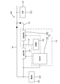
- One end of the resistor 33 is connected to the other end of the resistor 37 and the base of the transistor 41.
- One end of the resistor 33, the other end of the resistor 37, and the base of the transistor 41 have the same potential.
- One end of the resistor 35 is connected to the other end of the resistor 33 and the other end of the resistor 39.
- One end of the resistor 35, the other end of the resistor 33, and the other end of the resistor 39 have the same potential.
- the other end of the resistor 37 and the other end of the resistor 39 are connected to each of the inter-element conductive paths 93 and 94 in the series component 31.
- the other end of the resistor 35 is connected to the ground and has a ground potential.
- the control unit 20 operates so as to switch each state of the ports P1 and P2 to either the first state or the second state, thereby switching a plurality of types of Vb to the transistor 41. It can be applied to the base and the output voltage Vout can be changed accordingly. In this way, one voltage regulator 10 can output output voltages of a plurality of different sizes.
- the voltage regulator 10 can gradually switch the voltage applied to the base of the transistor 41 by controlling the plurality of ports P1 and P2 by the control unit 20, and such a configuration is defined as "a plurality of resistors 33, 35 and It can be realized by a simple configuration mainly composed of a plurality of resistors 37 and 39. Moreover, since the control unit 20 only needs to switch the plurality of ports P1 and P2 to the high level voltage or the low level voltage, the control of the control unit 20 is also simplified.
Landscapes
- Engineering & Computer Science (AREA)
- Physics & Mathematics (AREA)
- General Physics & Mathematics (AREA)
- Power Engineering (AREA)
- Theoretical Computer Science (AREA)
- Radar, Positioning & Navigation (AREA)
- Electromagnetism (AREA)
- Automation & Control Theory (AREA)
- Business, Economics & Management (AREA)
- Emergency Management (AREA)
- General Engineering & Computer Science (AREA)
- Continuous-Control Power Sources That Use Transistors (AREA)
- Stand-By Power Supply Arrangements (AREA)
- Direct Current Feeding And Distribution (AREA)
- Charge And Discharge Circuits For Batteries Or The Like (AREA)
Priority Applications (2)
| Application Number | Priority Date | Filing Date | Title |
|---|---|---|---|
| CN202080033029.3A CN113785255B (zh) | 2019-05-15 | 2020-04-27 | 电压调节器以及车载用的备用电源 |
| US17/610,568 US11841721B2 (en) | 2019-05-15 | 2020-04-27 | Voltage regulator and in-vehicle backup power supply |
Applications Claiming Priority (2)
| Application Number | Priority Date | Filing Date | Title |
|---|---|---|---|
| JP2019-091925 | 2019-05-15 | ||
| JP2019091925A JP7200823B2 (ja) | 2019-05-15 | 2019-05-15 | 電圧レギュレータ及び車載用のバックアップ電源 |
Publications (1)
| Publication Number | Publication Date |
|---|---|
| WO2020230605A1 true WO2020230605A1 (ja) | 2020-11-19 |
Family
ID=73222860
Family Applications (1)
| Application Number | Title | Priority Date | Filing Date |
|---|---|---|---|
| PCT/JP2020/017930 Ceased WO2020230605A1 (ja) | 2019-05-15 | 2020-04-27 | 電圧レギュレータ及び車載用のバックアップ電源 |
Country Status (4)
| Country | Link |
|---|---|
| US (1) | US11841721B2 (https=) |
| JP (1) | JP7200823B2 (https=) |
| CN (1) | CN113785255B (https=) |
| WO (1) | WO2020230605A1 (https=) |
Families Citing this family (2)
| Publication number | Priority date | Publication date | Assignee | Title |
|---|---|---|---|---|
| CN113763898A (zh) * | 2021-08-31 | 2021-12-07 | 惠科股份有限公司 | 控制电路及其驱动方法、显示装置 |
| CN116820172A (zh) * | 2023-04-18 | 2023-09-29 | 深圳蓝影医学科技股份有限公司 | 低压差线性稳压电路 |
Citations (3)
| Publication number | Priority date | Publication date | Assignee | Title |
|---|---|---|---|---|
| JPH0482711U (https=) * | 1990-11-28 | 1992-07-17 | ||
| JP2006293492A (ja) * | 2005-04-06 | 2006-10-26 | Denso Corp | 電源装置 |
| JP2010198405A (ja) * | 2009-02-26 | 2010-09-09 | Aiphone Co Ltd | 電源装置 |
Family Cites Families (21)
| Publication number | Priority date | Publication date | Assignee | Title |
|---|---|---|---|---|
| NL6809968A (https=) * | 1970-03-09 | 1969-01-21 | ||
| GB1405445A (en) * | 1971-09-25 | 1975-09-10 | Sony Corp | Transistor circuits |
| JPH0682306B2 (ja) * | 1989-05-29 | 1994-10-19 | 茨城日本電気株式会社 | 電源回路 |
| JP3131344B2 (ja) * | 1994-01-24 | 2001-01-31 | シャープ株式会社 | 減電圧感知遮断回路及びそれを用いたシーケンス回路 |
| JP3447106B2 (ja) * | 1994-04-06 | 2003-09-16 | ニチコン株式会社 | 半導体スイッチ回路 |
| JP3427088B2 (ja) * | 1994-09-30 | 2003-07-14 | ソニー株式会社 | スイッチング電源装置 |
| JPH09325824A (ja) * | 1996-06-07 | 1997-12-16 | Oki Electric Ind Co Ltd | 電源安定化回路 |
| JP3583866B2 (ja) * | 1996-08-07 | 2004-11-04 | 三洋電機株式会社 | 電源回路 |
| JPH1132475A (ja) * | 1997-07-10 | 1999-02-02 | Yahata Denki Sangyo Kk | 過電圧遮断型電源フィルタ装置 |
| JP3489438B2 (ja) * | 1998-04-27 | 2004-01-19 | 三菱電機株式会社 | 電池パック |
| JP2003258605A (ja) * | 2002-02-28 | 2003-09-12 | Nippon Telegr & Teleph Corp <Ntt> | 可変インピーダンス回路 |
| EP1439444A1 (en) * | 2003-01-16 | 2004-07-21 | Dialog Semiconductor GmbH | Low drop out voltage regulator having a cascode structure |
| JP2006067187A (ja) * | 2004-08-26 | 2006-03-09 | Matsushita Electric Ind Co Ltd | 過電圧過電流保護回路 |
| JP2006127093A (ja) * | 2004-10-28 | 2006-05-18 | Quanta Display Japan Inc | 定電圧レギュレータ回路 |
| JP4991336B2 (ja) * | 2007-02-15 | 2012-08-01 | 三洋電機株式会社 | 調整回路 |
| JP2012143030A (ja) * | 2010-12-28 | 2012-07-26 | Renesas Electronics Corp | 電子回路 |
| US8928296B2 (en) * | 2011-03-01 | 2015-01-06 | Analog Devices, Inc. | High power supply rejection ratio (PSRR) and low dropout regulator |
| US20150286232A1 (en) * | 2014-04-08 | 2015-10-08 | Fujitsu Limited | Voltage regulation circuit |
| JP2017004059A (ja) * | 2015-06-04 | 2017-01-05 | イサハヤ電子株式会社 | 定電圧回路 |
| US10038378B2 (en) * | 2016-09-21 | 2018-07-31 | Qualcomm Incorporated | Device and method to stabilize a supply voltage |
| CN106563857B (zh) * | 2016-10-18 | 2018-09-28 | 丁毅 | 一种电火花加工机床用脉冲电源 |
-
2019
- 2019-05-15 JP JP2019091925A patent/JP7200823B2/ja active Active
-
2020
- 2020-04-27 US US17/610,568 patent/US11841721B2/en active Active
- 2020-04-27 WO PCT/JP2020/017930 patent/WO2020230605A1/ja not_active Ceased
- 2020-04-27 CN CN202080033029.3A patent/CN113785255B/zh active Active
Patent Citations (3)
| Publication number | Priority date | Publication date | Assignee | Title |
|---|---|---|---|---|
| JPH0482711U (https=) * | 1990-11-28 | 1992-07-17 | ||
| JP2006293492A (ja) * | 2005-04-06 | 2006-10-26 | Denso Corp | 電源装置 |
| JP2010198405A (ja) * | 2009-02-26 | 2010-09-09 | Aiphone Co Ltd | 電源装置 |
Also Published As
| Publication number | Publication date |
|---|---|
| US11841721B2 (en) | 2023-12-12 |
| CN113785255A (zh) | 2021-12-10 |
| US20220221887A1 (en) | 2022-07-14 |
| JP7200823B2 (ja) | 2023-01-10 |
| CN113785255B (zh) | 2023-02-28 |
| JP2020187561A (ja) | 2020-11-19 |
Similar Documents
| Publication | Publication Date | Title |
|---|---|---|
| US11031771B2 (en) | Power supply control apparatus | |
| US20080018174A1 (en) | Power control apparatus and method thereof | |
| US10654428B2 (en) | Power supply control device | |
| EP3208940A1 (en) | A driver circuit, corresponding device and method | |
| WO2020230605A1 (ja) | 電圧レギュレータ及び車載用のバックアップ電源 | |
| JP6996446B2 (ja) | 回路装置 | |
| JP2020005344A (ja) | 給電制御装置 | |
| JP7082758B2 (ja) | 電圧レギュレータ及び車載用のバックアップ電源 | |
| US11824397B2 (en) | Pre-charge current control device | |
| US10396661B2 (en) | Power supply control apparatus | |
| JP7697348B2 (ja) | 制御装置 | |
| JP2021034839A (ja) | スイッチ装置 | |
| US11881850B2 (en) | Driving apparatus | |
| JP2020187560A5 (https=) | ||
| CN116057836A (zh) | 检测电路及供电控制装置 | |
| US20250199555A1 (en) | Voltage regulator with switching circuitry | |
| KR102818359B1 (ko) | 릴레이 구동회로 및 이를 포함하는 배터리 시스템 | |
| JP2018101882A (ja) | 出力ドライバ回路 | |
| KR100828260B1 (ko) | 역 접속 전원 차단 회로 및 이를 포함하는 모터 회로 | |
| CN107066012B (zh) | 一种开关电路及电子设备 | |
| WO2021131698A1 (ja) | 給電制御装置 | |
| KR20230091582A (ko) | 전자 장치의 온오프 동작 제어 시스템 |
Legal Events
| Date | Code | Title | Description |
|---|---|---|---|
| 121 | Ep: the epo has been informed by wipo that ep was designated in this application |
Ref document number: 20805401 Country of ref document: EP Kind code of ref document: A1 |
|
| NENP | Non-entry into the national phase |
Ref country code: DE |
|
| 122 | Ep: pct application non-entry in european phase |
Ref document number: 20805401 Country of ref document: EP Kind code of ref document: A1 |