WO2020208459A1 - 正極活物質の作製方法 - Google Patents
正極活物質の作製方法 Download PDFInfo
- Publication number
- WO2020208459A1 WO2020208459A1 PCT/IB2020/052989 IB2020052989W WO2020208459A1 WO 2020208459 A1 WO2020208459 A1 WO 2020208459A1 IB 2020052989 W IB2020052989 W IB 2020052989W WO 2020208459 A1 WO2020208459 A1 WO 2020208459A1
- Authority
- WO
- WIPO (PCT)
- Prior art keywords
- positive electrode
- active material
- secondary battery
- electrode active
- metal
- Prior art date
- Legal status (The legal status is an assumption and is not a legal conclusion. Google has not performed a legal analysis and makes no representation as to the accuracy of the status listed.)
- Ceased
Links
Images





















Classifications
-
- H—ELECTRICITY
- H01—ELECTRIC ELEMENTS
- H01M—PROCESSES OR MEANS, e.g. BATTERIES, FOR THE DIRECT CONVERSION OF CHEMICAL ENERGY INTO ELECTRICAL ENERGY
- H01M4/00—Electrodes
- H01M4/02—Electrodes composed of, or comprising, active material
- H01M4/36—Selection of substances as active materials, active masses, active liquids
- H01M4/362—Composites
- H01M4/366—Composites as layered products
-
- H—ELECTRICITY
- H01—ELECTRIC ELEMENTS
- H01M—PROCESSES OR MEANS, e.g. BATTERIES, FOR THE DIRECT CONVERSION OF CHEMICAL ENERGY INTO ELECTRICAL ENERGY
- H01M4/00—Electrodes
- H01M4/02—Electrodes composed of, or comprising, active material
- H01M4/36—Selection of substances as active materials, active masses, active liquids
- H01M4/48—Selection of substances as active materials, active masses, active liquids of inorganic oxides or hydroxides
- H01M4/50—Selection of substances as active materials, active masses, active liquids of inorganic oxides or hydroxides of manganese
- H01M4/505—Selection of substances as active materials, active masses, active liquids of inorganic oxides or hydroxides of manganese of mixed oxides or hydroxides containing manganese for inserting or intercalating light metals, e.g. LiMn2O4 or LiMn2OxFy
-
- C—CHEMISTRY; METALLURGY
- C01—INORGANIC CHEMISTRY
- C01G—COMPOUNDS CONTAINING METALS NOT COVERED BY SUBCLASSES C01D OR C01F
- C01G51/00—Compounds of cobalt
- C01G51/40—Complex oxides containing cobalt and at least one other metal element
- C01G51/42—Complex oxides containing cobalt and at least one other metal element containing alkali metals, e.g. LiCoO2
-
- C—CHEMISTRY; METALLURGY
- C01—INORGANIC CHEMISTRY
- C01G—COMPOUNDS CONTAINING METALS NOT COVERED BY SUBCLASSES C01D OR C01F
- C01G53/00—Compounds of nickel
-
- H—ELECTRICITY
- H01—ELECTRIC ELEMENTS
- H01M—PROCESSES OR MEANS, e.g. BATTERIES, FOR THE DIRECT CONVERSION OF CHEMICAL ENERGY INTO ELECTRICAL ENERGY
- H01M4/00—Electrodes
- H01M4/02—Electrodes composed of, or comprising, active material
- H01M4/04—Processes of manufacture in general
- H01M4/043—Processes of manufacture in general involving compressing or compaction
-
- H—ELECTRICITY
- H01—ELECTRIC ELEMENTS
- H01M—PROCESSES OR MEANS, e.g. BATTERIES, FOR THE DIRECT CONVERSION OF CHEMICAL ENERGY INTO ELECTRICAL ENERGY
- H01M4/00—Electrodes
- H01M4/02—Electrodes composed of, or comprising, active material
- H01M4/04—Processes of manufacture in general
- H01M4/0471—Processes of manufacture in general involving thermal treatment, e.g. firing, sintering, backing particulate active material, thermal decomposition, pyrolysis
-
- H—ELECTRICITY
- H01—ELECTRIC ELEMENTS
- H01M—PROCESSES OR MEANS, e.g. BATTERIES, FOR THE DIRECT CONVERSION OF CHEMICAL ENERGY INTO ELECTRICAL ENERGY
- H01M4/00—Electrodes
- H01M4/02—Electrodes composed of, or comprising, active material
- H01M4/36—Selection of substances as active materials, active masses, active liquids
-
- H—ELECTRICITY
- H01—ELECTRIC ELEMENTS
- H01M—PROCESSES OR MEANS, e.g. BATTERIES, FOR THE DIRECT CONVERSION OF CHEMICAL ENERGY INTO ELECTRICAL ENERGY
- H01M4/00—Electrodes
- H01M4/02—Electrodes composed of, or comprising, active material
- H01M4/36—Selection of substances as active materials, active masses, active liquids
- H01M4/362—Composites
- H01M4/364—Composites as mixtures
-
- H—ELECTRICITY
- H01—ELECTRIC ELEMENTS
- H01M—PROCESSES OR MEANS, e.g. BATTERIES, FOR THE DIRECT CONVERSION OF CHEMICAL ENERGY INTO ELECTRICAL ENERGY
- H01M4/00—Electrodes
- H01M4/02—Electrodes composed of, or comprising, active material
- H01M4/36—Selection of substances as active materials, active masses, active liquids
- H01M4/48—Selection of substances as active materials, active masses, active liquids of inorganic oxides or hydroxides
- H01M4/52—Selection of substances as active materials, active masses, active liquids of inorganic oxides or hydroxides of nickel, cobalt or iron
- H01M4/525—Selection of substances as active materials, active masses, active liquids of inorganic oxides or hydroxides of nickel, cobalt or iron of mixed oxides or hydroxides containing iron, cobalt or nickel for inserting or intercalating light metals, e.g. LiNiO2, LiCoO2 or LiCoOxFy
-
- H—ELECTRICITY
- H01—ELECTRIC ELEMENTS
- H01M—PROCESSES OR MEANS, e.g. BATTERIES, FOR THE DIRECT CONVERSION OF CHEMICAL ENERGY INTO ELECTRICAL ENERGY
- H01M4/00—Electrodes
- H01M4/02—Electrodes composed of, or comprising, active material
- H01M4/36—Selection of substances as active materials, active masses, active liquids
- H01M4/58—Selection of substances as active materials, active masses, active liquids of inorganic compounds other than oxides or hydroxides, e.g. sulfides, selenides, tellurides, halogenides or LiCoFy; of polyanionic structures, e.g. phosphates, silicates or borates
- H01M4/582—Halogenides
-
- C—CHEMISTRY; METALLURGY
- C01—INORGANIC CHEMISTRY
- C01P—INDEXING SCHEME RELATING TO STRUCTURAL AND PHYSICAL ASPECTS OF SOLID INORGANIC COMPOUNDS
- C01P2004/00—Particle morphology
- C01P2004/80—Particles consisting of a mixture of two or more inorganic phases
-
- H—ELECTRICITY
- H01—ELECTRIC ELEMENTS
- H01M—PROCESSES OR MEANS, e.g. BATTERIES, FOR THE DIRECT CONVERSION OF CHEMICAL ENERGY INTO ELECTRICAL ENERGY
- H01M10/00—Secondary cells; Manufacture thereof
- H01M10/05—Accumulators with non-aqueous electrolyte
- H01M10/052—Li-accumulators
-
- H—ELECTRICITY
- H01—ELECTRIC ELEMENTS
- H01M—PROCESSES OR MEANS, e.g. BATTERIES, FOR THE DIRECT CONVERSION OF CHEMICAL ENERGY INTO ELECTRICAL ENERGY
- H01M4/00—Electrodes
- H01M4/02—Electrodes composed of, or comprising, active material
- H01M2004/021—Physical characteristics, e.g. porosity, surface area
-
- H—ELECTRICITY
- H01—ELECTRIC ELEMENTS
- H01M—PROCESSES OR MEANS, e.g. BATTERIES, FOR THE DIRECT CONVERSION OF CHEMICAL ENERGY INTO ELECTRICAL ENERGY
- H01M4/00—Electrodes
- H01M4/02—Electrodes composed of, or comprising, active material
- H01M2004/026—Electrodes composed of, or comprising, active material characterised by the polarity
- H01M2004/028—Positive electrodes
-
- H—ELECTRICITY
- H01—ELECTRIC ELEMENTS
- H01M—PROCESSES OR MEANS, e.g. BATTERIES, FOR THE DIRECT CONVERSION OF CHEMICAL ENERGY INTO ELECTRICAL ENERGY
- H01M4/00—Electrodes
- H01M4/02—Electrodes composed of, or comprising, active material
- H01M4/62—Selection of inactive substances as ingredients for active masses, e.g. binders, fillers
-
- Y—GENERAL TAGGING OF NEW TECHNOLOGICAL DEVELOPMENTS; GENERAL TAGGING OF CROSS-SECTIONAL TECHNOLOGIES SPANNING OVER SEVERAL SECTIONS OF THE IPC; TECHNICAL SUBJECTS COVERED BY FORMER USPC CROSS-REFERENCE ART COLLECTIONS [XRACs] AND DIGESTS
- Y02—TECHNOLOGIES OR APPLICATIONS FOR MITIGATION OR ADAPTATION AGAINST CLIMATE CHANGE
- Y02E—REDUCTION OF GREENHOUSE GAS [GHG] EMISSIONS, RELATED TO ENERGY GENERATION, TRANSMISSION OR DISTRIBUTION
- Y02E60/00—Enabling technologies; Technologies with a potential or indirect contribution to GHG emissions mitigation
- Y02E60/10—Energy storage using batteries
Definitions
- One aspect of the present invention relates to a product, a method, or a manufacturing method. Alternatively, one aspect of the invention relates to a process, machine, manufacture, or composition (composition of matter).
- One aspect of the present invention relates to a semiconductor device, a display device, a light emitting device, a power storage device, a lighting device or an electronic device, or a method for manufacturing the same.
- the present invention relates to a positive electrode active material that can be used for a secondary battery, a secondary battery, and an electronic device having the secondary battery.
- the power storage device refers to an element having a power storage function and a device in general.
- a storage battery also referred to as a secondary battery
- a lithium ion secondary battery such as a lithium ion secondary battery, a lithium ion capacitor, an electric double layer capacitor, and the like.
- the electronic device refers to all devices having a power storage device, and an electro-optical device having a power storage device, an information terminal device having a power storage device, and the like are all electronic devices.
- Lithium-ion secondary batteries which have particularly high output and high energy density, are mobile information terminals such as mobile phones, smartphones, tablets, or notebook computers, portable music players, digital cameras, medical devices, and next-generation clean energy vehicles (hybrid).
- HVs high output and high energy density
- EVs electric vehicles
- PSVs plug-in hybrid vehicles
- the characteristics required for lithium-ion secondary batteries include further high energy density, improvement of cycle characteristics, safety in various operating environments, and improvement of long-term reliability.
- Patent Document 1 and Patent Document 2 Improvement of the positive electrode active material with the aim of improving the cycle characteristics and increasing the capacity of the lithium ion secondary battery is being studied.
- Patent Documents 1 to 3 Research on the crystal structure of the positive electrode active material has also been conducted.
- Non-Patent Document 4 describes the physical properties of metal fluoride.
- X-ray diffraction is one of the methods used for analyzing the crystal structure of the positive electrode active material.
- XRD data can be analyzed by using ICSD (Inorganic Crystal Structure Database) introduced in Non-Patent Document 5.
- One aspect of the present invention is to provide a positive electrode active material for a lithium ion secondary battery having a high capacity and excellent charge / discharge cycle characteristics, and a method for producing the same.
- one aspect of the present invention is to provide a method for producing a positive electrode active material having high productivity.
- one aspect of the present invention is to provide a positive electrode active material in which a decrease in capacity in a charge / discharge cycle is suppressed by using it in a lithium ion secondary battery.
- one aspect of the present invention is to provide a high-capacity secondary battery.
- one aspect of the present invention is to provide a secondary battery having excellent charge / discharge characteristics.
- one aspect of the present invention is to provide a positive electrode active material in which elution of transition metals such as cobalt is suppressed even when the state of being charged at a high voltage is held for a long time.
- one aspect of the present invention is to provide a secondary battery having high safety or reliability.
- one aspect of the present invention is to provide a novel substance, active material particles, a power storage device, or a method for producing them.
- a compound having an element X, a compound having a halogen and an alkali metal, and a metal fluoride are each pulverized and then mixed with a metal oxide powder to prepare a first mixture. It has a first step and a second step of heating at a temperature of 700 ° C. or higher and 950 ° C. or lower, and the element X is one or more selected from magnesium, calcium, zirconium, lanthanum and barium, and is a metal fluoride.
- the average particle size of the obtained positive electrode active material is preferably 1 ⁇ m or more and 100 ⁇ m or less.
- the metal oxide preferably has a structure represented by the space group R-3m. Further, in the above configuration, the metal oxide is preferably lithium cobalt oxide.
- one aspect of the present invention is a first step of preparing a first mixture by pulverizing magnesium fluoride, lithium fluoride, and aluminum fluoride, respectively, and then mixing them with a powder of a metal oxide. And a second step of heating at a temperature of 700 ° C. or higher and 950 ° C. or lower, the metal oxide has a metal M, and the metal M is a positive electrode active material selected from cobalt, manganese, nickel and iron. It is a manufacturing method of.
- the number of atoms of magnesium contained in magnesium fluoride is preferably 0.005 times or more and 0.05 times or less the number of atoms of metal M contained in the metal oxide.
- the number of aluminum atoms of aluminum fluoride is 0.0005 times or more the sum of the number of atoms of metal M of the metal oxide and the number of atoms of aluminum of aluminum fluoride. It is preferably 0.02 times or less.
- the average particle size of the obtained positive electrode active material is preferably 1 ⁇ m or more and 100 ⁇ m or less.
- the metal oxide preferably has a structure represented by the space group R-3m. Further, in the above configuration, the metal oxide is preferably lithium cobalt oxide.
- one aspect of the present invention is to prepare a first mixture by pulverizing magnesium fluoride, lithium fluoride, a nickel compound, and aluminum fluoride, and then mixing them with a powder of a metal oxide. It has a first step and a second step of heating at a temperature of 700 ° C. or higher and 950 ° C. or lower, the metal oxide having a metal M, and the metal M being selected from cobalt, manganese, nickel and iron. It is a method for producing one or more positive electrode active materials.
- the nickel compound is preferably nickel hydroxide.
- the number of atoms of magnesium contained in magnesium fluoride is preferably 0.005 times or more and 0.05 times or less the number of atoms of metal M contained in the metal oxide.
- the number of aluminum atoms of aluminum fluoride is 0.0005 times or more the sum of the number of atoms of metal M of the metal oxide and the number of atoms of aluminum of aluminum fluoride. It is preferably 0.02 times or less.
- the average particle size of the obtained positive electrode active material is preferably 1 ⁇ m or more and 100 ⁇ m or less.
- the metal oxide preferably has a structure represented by the space group R-3m. Further, in the above configuration, the metal oxide is preferably lithium cobalt oxide.
- a positive electrode active material for a lithium ion secondary battery having a high capacity and excellent charge / discharge cycle characteristics it is possible to provide a method for producing the same. Further, it is possible to provide a method for producing a positive electrode active material having good productivity. Further, by using it in a lithium ion secondary battery, it is possible to provide a positive electrode active material in which a decrease in capacity in a charge / discharge cycle is suppressed. In addition, a high-capacity secondary battery can be provided. Further, it is possible to provide a secondary battery having excellent charge / discharge characteristics.
- FIG. 1A is a diagram illustrating a method for producing a substance.
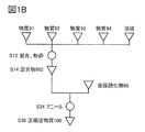
- FIG. 1B is a diagram illustrating a method for producing a substance.
- FIG. 2A is a diagram illustrating a method for producing a positive electrode active material.
- FIG. 2B is a diagram illustrating a method for producing a positive electrode active material.
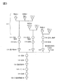
- FIG. 3 is a diagram illustrating a method for producing a positive electrode active material.
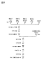
- FIG. 4 is a diagram illustrating a method for producing a positive electrode active material.
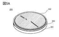
- FIG. 5A is a diagram illustrating a coin-type secondary battery.
- FIG. 5B is a diagram illustrating a coin-type secondary battery.
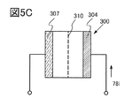
- FIG. 5C is a diagram illustrating charging of the secondary battery.
- FIG. 6A is a diagram illustrating a cylindrical secondary battery.
- FIG. 6B is a diagram illustrating a cylindrical secondary battery.
- FIG. 6C is a diagram illustrating a cylindrical secondary battery.
- FIG. 6D is a diagram illustrating a cylindrical secondary battery.
- FIG. 7A is a diagram illustrating an example of a secondary battery.
- FIG. 7B is a diagram illustrating an example of a secondary battery.
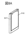
- FIG. 8A is a diagram illustrating an example of a secondary battery.
- FIG. 8B is a diagram illustrating an example of a secondary battery.
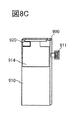
- FIG. 8C is a diagram illustrating an example of a secondary battery.
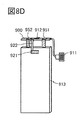
- FIG. 8D is a diagram illustrating an example of a secondary battery.
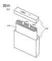
- FIG. 9A is a diagram illustrating an example of a secondary battery.
- FIG. 9B is a diagram illustrating an example of a secondary battery.
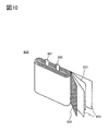
- FIG. 10 is a diagram illustrating an example of a secondary battery.
- FIG. 11A is a diagram illustrating a laminated type secondary battery.
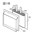
- FIG. 11B is a diagram illustrating a laminated type secondary battery.
- FIG. 11C is a diagram illustrating a laminated type secondary battery.
- FIG. 12A is a diagram illustrating a laminated type secondary battery.
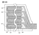
- FIG. 12B is a diagram illustrating a laminated type secondary battery.
- FIG. 13 is a diagram showing the appearance of the secondary battery.
- FIG. 14 is a diagram showing the appearance of the secondary battery.
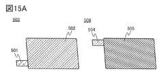
- FIG. 15A is a diagram for explaining a method of manufacturing a secondary battery.
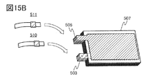
- FIG. 15B is a diagram for explaining a method of manufacturing a secondary battery.
- FIG. 15A is a diagram for explaining a method of manufacturing a secondary battery.
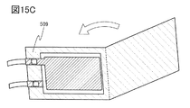
- FIG. 15C is a diagram for explaining a method of manufacturing a secondary battery.
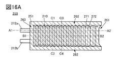
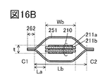
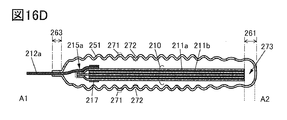
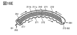
- FIG. 16A is a diagram illustrating a bendable secondary battery.
- FIG. 16B is a diagram illustrating a bendable secondary battery.
- FIG. 16C is a diagram illustrating a bendable secondary battery.
- FIG. 16D is a diagram illustrating a bendable secondary battery.
- FIG. 16E is a diagram illustrating a bendable secondary battery.
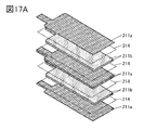
- FIG. 17A is a diagram illustrating a bendable secondary battery.
- FIG. 17B is a diagram illustrating a bendable secondary battery.
- FIG. 18A is a diagram illustrating an example of an electronic device.
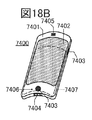
- FIG. 18B is a diagram illustrating an example of an electronic device.
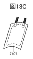
- FIG. 18C is a diagram illustrating an example of a secondary battery.
- FIG. 18A is a diagram illustrating an example of an electronic device.
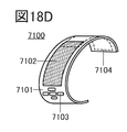
- FIG. 18D is a diagram illustrating an example of an electronic device.
- FIG. 18E is a diagram illustrating an example of a secondary battery.
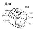
- FIG. 18F is a diagram illustrating an example of an electronic device.
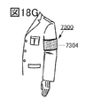
- FIG. 18G is a diagram illustrating an example of an electronic device.
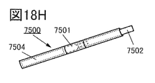
- FIG. 18H is a diagram illustrating an example of an electronic device.
- FIG. 19A is a diagram illustrating an example of an electronic device.
- FIG. 19B is a diagram illustrating an example of an electronic device.
- FIG. 19C is a diagram illustrating an example of an electronic device.
- FIG. 20 is a diagram illustrating an example of an electronic device.
- FIG. 21A is a diagram illustrating an example of a vehicle.
- FIG. 21B is a diagram illustrating an example of a vehicle.
- FIG. 21A is a diagram illustrating an example of a vehicle.
- FIG. 21C is a diagram illustrating an example of a vehicle.
- FIG. 22A is a diagram illustrating an example of an electronic device.
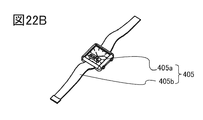
- FIG. 22B is a diagram illustrating an example of an electronic device.
- FIG. 22C is a diagram illustrating an example of an electronic device.
- FIG. 23 is a diagram showing DSC.
- FIG. 24 is a diagram showing DSC.
- FIG. 25 is a diagram showing DSC.
- FIG. 26A is a diagram showing the cycle characteristics of the secondary battery.
- FIG. 26B is a diagram showing the cycle characteristics of the secondary battery.
- FIG. 27A is a diagram showing the cycle characteristics of the secondary battery.
- FIG. 27B is a diagram showing the cycle characteristics of the secondary battery.
- the crystal plane and the direction are indicated by the Miller index.
- the notation of crystal plane and direction is to add a superscript bar to the number, but in this specification etc., due to the limitation of application notation, instead of adding a bar above the number,-(minus) before the number. It may be expressed with a sign).
- the individual orientation indicating the direction in the crystal is []
- the aggregate orientation indicating all the equivalent directions is ⁇ >
- the individual plane indicating the crystal plane is ()
- the aggregate plane having equivalent symmetry is ⁇ . Express each with.
- segregation refers to a phenomenon in which a certain element (for example, B) is spatially unevenly distributed in a solid composed of a plurality of elements (for example, A, B, C).
- the surface layer portion of particles such as active material means a region from the surface to about 10 nm.
- the surface created by cracks and cracks can also be called the surface.
- the area deeper than the surface layer is called the inside.
- the layered rock salt type crystal structure of the composite oxide containing lithium and the transition metal has a rock salt type ion arrangement in which cations and anions are alternately arranged, and the transition metal and lithium are present.
- a crystal structure capable of two-dimensional diffusion of lithium because it is regularly arranged to form a two-dimensional plane.
- the layered rock salt crystal structure may have a distorted lattice of rock salt crystals.
- the rock salt type crystal structure means a structure in which cations and anions are alternately arranged. There may be a cation or anion deficiency.
- the pseudo-spinel-type crystal structure of the composite oxide containing lithium and the transition metal is the space group R-3 m, and although it is not a spinel-type crystal structure, ions such as cobalt and magnesium are present.
- a light element such as lithium may occupy the oxygen 4-coordination position, and in this case as well, the ion arrangement has symmetry similar to that of the spinel type.
- the pseudo-spinel type crystal structure has Li randomly between layers, but is similar to the CdCl 2 type crystal structure.
- This crystal structure similar to CdCl type 2 is similar to the crystal structure when lithium nickel oxide is charged to a charging depth of 0.94 (Li 0.06 NiO 2 ), but contains a large amount of pure lithium cobalt oxide or cobalt. It is known that the layered rock salt type positive electrode active material usually does not have this crystal structure.
- Layered rock salt crystals and anions of rock salt crystals have a cubic closest packed structure (face-centered cubic lattice structure). Pseudo-spinel-type crystals are also presumed to have a cubic close-packed structure with anions. When they come into contact, there is a crystal plane in which the cubic close-packed structure composed of anions is oriented in the same direction.
- the space group of layered rock salt type crystals and pseudo-spinel type crystals is R-3m
- the space group of rock salt type crystals Fm-3m (space group of general rock salt type crystals) and Fd-3m (the simplest symmetry).
- the mirror index of the crystal plane satisfying the above conditions is different between the layered rock salt type crystal and the pseudo spinel type crystal and the rock salt type crystal.
- the orientations of the crystals are substantially the same when the orientations of the cubic closest packed structures composed of anions are aligned. is there.
- TEM transmission electron microscope
- STEM scanning transmission electron microscope
- HAADF-SFEM high-angle scattering annular dark-field scanning transmission electron microscope
- ABF-STEM that the orientations of the crystals in the two regions are roughly the same.
- the angle formed by the repetition of the bright line and the dark line between the crystals is 5 degrees or less, more preferably 2.5 degrees or less. It can be observed.
- light elements such as oxygen and fluorine may not be clearly observed in the TEM image or the like, but in that case, the alignment of the metal elements can be used to determine the alignment.
- the theoretical capacity of the positive electrode active material means the amount of electricity when all the lithium that can be inserted and removed from the positive electrode active material is desorbed.
- the theoretical capacity of LiCoO 2 is 274 mAh / g
- the theoretical capacity of LiNiO 2 is 274 mAh / g
- the theoretical capacity of LiMn 2 O 4 is 148 mAh / g.
- the charging depth when all the insertable and detachable lithium is inserted is 0, and the charging depth when all the insertable and detachable lithium contained in the positive electrode active material is desorbed is 1. And.
- charging means moving lithium ions from the positive electrode to the negative electrode in the battery and moving electrons from the positive electrode to the negative electrode in an external circuit.
- the positive electrode active material the release of lithium ions is called charging.
- a positive electrode active material having a charging depth of 0.7 or more and 0.9 or less may be referred to as a positive electrode active material charged at a high voltage.
- discharging means moving lithium ions from the negative electrode to the positive electrode in the battery and moving electrons from the negative electrode to the positive electrode in an external circuit.
- inserting lithium ions is called electric discharge.
- a positive electrode active material having a charging depth of 0.06 or less, or a positive electrode active material in which a capacity of 90% or more of the charging capacity is discharged from a state of being charged at a high voltage is defined as a sufficiently discharged positive electrode active material. ..
- the non-equilibrium phase change means a phenomenon that causes a non-linear change of a physical quantity.
- a non-equilibrium phase change occurs before and after the peak in the dQ / dV curve obtained by differentiating the capacitance (Q) with the voltage (V) (dQ / dV), and the crystal structure changes significantly. ..
- the secondary battery has, for example, a positive electrode and a negative electrode.
- a positive electrode active material As a material constituting the positive electrode, there is a positive electrode active material.
- the positive electrode active material is, for example, a substance that undergoes a reaction that contributes to the charge / discharge capacity.
- the positive electrode active material may contain a substance that does not contribute to the charge / discharge capacity.
- the positive electrode active material of one aspect of the present invention may be expressed as a positive electrode material, a positive electrode material for a secondary battery, or the like. Further, in the present specification and the like, the positive electrode active material according to one aspect of the present invention preferably has a compound. Further, in the present specification and the like, the positive electrode active material according to one aspect of the present invention preferably has a composition. Further, in the present specification and the like, the positive electrode active material according to one aspect of the present invention preferably has a complex.
- the discharge rate is the relative ratio of the current at the time of discharge to the battery capacity, and is expressed in the unit C.
- the current corresponding to 1C is X (A).
- X (A) When discharged with a current of 2X (A), it is said to be discharged at 2C, and when discharged with a current of X / 5 (A), it is said to be discharged at 0.2C.
- the charging rate is also the same.
- When charged with a current of 2X (A) it is said to be charged with 2C, and when charged with a current of X / 5 (A), it is charged with 0.2C. It is said that
- Constant current charging refers to, for example, a method of charging with a constant charging rate.
- Constant voltage charging refers to, for example, a method of charging by keeping the voltage constant when the upper limit voltage is reached in charging.
- the constant current discharge refers to, for example, a method of discharging with a constant discharge rate.
- the positive electrode active material of one aspect of the present invention has a metal A, a transition metal Mt, an element X, a metal M (2) and oxygen. Moreover, the positive electrode active material of one aspect of the present invention may have a metal M (1).
- Metal A is an alkali metal.
- an alkaline earth metal may be used as the metal A.
- the transition metal Mt is preferably one or more of, for example, cobalt, manganese, nickel and iron.
- Element X is one or more selected from, for example, magnesium, calcium, zirconium, lanthanum and barium.
- the positive electrode active material of one aspect of the present invention has the element X, the structural stability of the positive electrode active material can be improved even in a secondary battery using the positive electrode active material of one aspect of the present invention, for example, even at a high charging voltage. Can be enhanced. By increasing the charging voltage, the discharge capacity and energy density can be increased. In addition, the cycle characteristics and the like can be improved by increasing the stability of the structure.
- the metal M (2) is, for example, one or more selected from nickel, aluminum, manganese, titanium, vanadium, iron and chromium, particularly preferably one or more of nickel and aluminum, and more preferably aluminum.
- the metal M (1) is preferably one or more selected from, for example, nickel, aluminum, manganese, titanium, vanadium, iron and chromium, and is a metal different from the metal M (2).
- the transition metal Mt is preferably a metal different from the metal M (2). Further, the transition metal Mt is more preferably a metal different from the metal M (1) and the metal M (2).
- the positive electrode active material of one aspect of the present invention has the metal M (2) in addition to the element X, for example, safety may be enhanced in a secondary battery using the positive electrode active material of one aspect of the present invention. .. Further, at a high charging voltage, the structural stability of the positive electrode active material may be further enhanced. In addition, the charging voltage may be further increased.
- the positive electrode active material of one aspect of the present invention is, for example, in a secondary battery using the positive electrode active material of the present invention.
- the structural stability of the positive electrode active material may be further enhanced.
- the discharge capacity may be further increased.
- a metal oxide having a metal A and a transition metal Mt (hereinafter, metal oxide 95) and a plurality of substances (hereinafter, substance 91, substance 92, substance 93 and substance 94) are mixed.
- Mixing and annealing are performed (step S34) to obtain a positive electrode active material 100 (step S36).
- four substances are shown as examples as a plurality of substances, but the plurality of substances may be three or less, or five or more.
- the plurality of substances may be three substances 91, 92 and 94.
- step S12 substances 91 to 94 are prepared, mixed and pulverized in step S12 to prepare a mixture 902 (step S14), and the mixture 902 and the metal oxide 95 are mixed and annealed. (Step 34), the positive electrode active material 100 is obtained (step S36).
- the substance 91 to the substance 94 may easily adhere to the surface of the metal oxide 95 in the annealing step of step S34.
- the contact area between the metal oxide 95 and the substance 91 to 94 may increase. Therefore, it may be easy to add one or more of the elements contained in the substance 91 to the substance 94 to the metal oxide 95.
- FIG. 1B an example in which a solvent is prepared together with the substances 91 to 94 and mixed by a wet method is shown, but when mixing by a dry method, it is not necessary to prepare a solvent.
- the metal oxide 95 is preferably particles.
- the metal oxide 95 may be a thin film formed by using a CVD (Chemical Vapor Deposition) method, a sputtering method, a vapor deposition method, or the like.
- the thin film is formed, for example, on a substrate.
- the substrate for example, various forms such as a foil of a material that can be used for a current collector, a glass substrate, a resin substrate, and the like, which will be described later, can be used.
- metal oxide 95 for example, an oxide having a layered rock salt type crystal structure can be used. Alternatively, for example, an oxide having a spinel-type crystal structure can be used. Alternatively, for example, a phosphoric acid compound, a silicic acid compound, or the like may be used as the metal oxide 95.
- the metal oxide 95 is an oxide having a layered rock salt type crystal structure
- cobalt, manganese, nickel, aluminum or the like may be used as the transition metal Mt.
- the material having such a transition metal Mt include lithium cobalt oxide, lithium manganate, lithium nickel oxide, lithium cobalt oxide in which a part of cobalt is substituted with manganese, and cobalt in which a part of cobalt is substituted with nickel.
- Examples thereof include lithium oxide or nickel-manganese-lithium cobalt oxide.
- metal oxide 95 for example, an oxide having a structure represented by the space group R-3m may be used.
- the metal oxide 95 is an oxide having a spinel-type crystal structure
- manganese, nickel, or the like may be used as the transition metal Mt.
- the elements contained in the substance 91 to the substance 94 are added to the surface of the metal oxide 95, a region near the surface, or the inside by the above mixing and annealing. Further, by the above mixing and annealing, a part of the elements contained in the metal oxide 95 may be replaced with a part of the elements contained in the substance 91 to the substance 94.
- a halogen compound having a metal A can be used as the substance 91.
- lithium when lithium is used as the metal A, for example, lithium fluoride, lithium chloride, etc. can be used as the substance 91.
- Lithium fluoride is particularly preferable because it easily melts in the annealing step described later.
- sodium when sodium is used as the metal A, for example, sodium fluoride, sodium chloride, or the like can be used as the substance 91.
- potassium when potassium is used as the metal A, for example, potassium fluoride or the like can be used as the substance 91.
- calcium is used as the metal A, for example, calcium chloride or the like can be used as the substance 91.
- the substance 92 is a compound having an element X.
- magnesium fluoride for example, magnesium fluoride, magnesium oxide, magnesium hydroxide, magnesium carbonate, magnesium chloride, etc. can be used as the substance 92.
- the concentration of the element X on the surface and in the vicinity of the surface of the metal oxide 95 can be made higher than the concentration inside.
- the value of the ratio of the number of atoms of the element X (Ax1) to the number of atoms of the transition metal Mt (Am1) in the first region where the distance from the surface is 20 nm or more and 200 nm or less ⁇ (Ax1) / (Am1) ⁇ Is the value of the ratio of the number of atoms of the element X (Ax2) to the number of atoms of the transition metal Mt (Am2) in the second region where the distance from the surface is 1 ⁇ m or more and 3 ⁇ m or less ⁇ (Ax2) / (Am2) ⁇ . Higher than.
- the substance 91 and the substance 92 are mixed and annealed to cause a eutectic reaction. Alternatively, it is preferable that the co-melting point is lowered. Alternatively, it is preferable that a eutectic reaction occurs. Alternatively, it is preferable that the eutectic point is lowered.
- the description may be applied to a decrease in the eutectic melting point, a eutectic reaction, and a decrease in the eutectic point.
- Substance 93 is a compound having metal M (1).
- the substance 94 is a compound having the metal M (2).
- the substance 93 and the substance 94 preferably function as metal sources in the production of the positive electrode active material according to one aspect of the present invention.
- the value of the ratio of the number of atoms (Amb1) of the metal M (2) to the number of atoms (Am1) of the transition metal Mt in the first region where the distance from the surface is 20 nm or more and 200 nm or less ⁇ (Amb1) / ( Am1) ⁇ is the value of the ratio of the number of atoms of the element X (Amb2) to the number of atoms of the transition metal Mt (Am2) in the second region where the distance from the surface is 1 ⁇ m or more and 3 ⁇ m or less ⁇ (Amb2) / ( Higher than Am2) ⁇ .
- the annealing may be divided into two parts as shown in FIGS. 2A and 2B. .. More specifically, a substance other than the substance that inhibits the eutectic reaction was mixed and annealed (step S34), and one or more of the elements possessed by at least one of the substance 91 and the substance 92 was added to the metal oxide 95. Then, a substance that inhibits the eutectic reaction is added, mixed, and annealed (step S55) to obtain a positive electrode active material 100 (step S36).
- the substance 91, the substance 92 and the metal oxide 95 are mixed and annealed (step S34), and the substance 93, the substance 94 and the annealed mixture are mixed and annealed (step S55), and the positive electrode is formed.
- the active material 100 is obtained (step S36).
- the substance 91, the substance 92, the substance 93 and the metal oxide 95 are mixed and annealed (step S34), and the substance 94 and the annealed mixture are mixed and annealed (step S55), and the positive electrode activity is performed.
- the step of FIG. 2A or FIG. 2B may be used.
- the step of FIG. 2A may be used.
- the substance 93 and the substance 94 do not inhibit the eutectic reaction between the substance 91 and the substance 92 as much as possible. More specifically, for example, the substance 93 and the substance 94 preferably have high stability at a temperature lower than the temperature at which the eutectic reaction between the substance 91 and the substance 92 occurs. For example, it is preferable that the reactivity with the element X is low at a temperature lower than the temperature at which the eutectic reaction occurs.
- the melting points of the substance 93 and the substance 94 are not too high above the temperature of the annealing step.
- the difference between the temperature of the annealing step and the melting point is preferably 500 ° C. or lower, more preferably 400 ° C. or lower, still more preferably 300 ° C. or lower.
- either or both of the substance 93 and the substance 94 may cause a eutectic reaction.
- the eutectic reaction can be evaluated using, for example, DSC (Different Scanning calorimetry).
- the DSC scans the measured temperature and observes changes in the amount of heat. This change in calorific value is caused by, for example, an endothermic reaction such as melting or an exothermic reaction such as crystallization.
- FIG. 23 shows an example of DSC of a mixture of substance 91 and substance 92.
- lithium fluoride is used as the substance 91
- magnesium fluoride is used as the substance 92.
- FIG. 24 shows an example of DSC of a mixture of substance 91, substance 92 and substance 94.
- lithium fluoride is used as the substance 91
- magnesium fluoride is used as the substance 92
- aluminum hydroxide is used as the substance 94.
- FIG. 25 shows an example of DSC of a mixture of substance 91, substance 92 and substance 94.
- lithium fluoride is used as the substance 91
- magnesium fluoride is used as the substance 92
- aluminum fluoride is used as the substance 94.
- Table 1 shows substance 91, substance 92 and substance 94 corresponding to FIGS. 23, 24 and 25.
- Lithium fluoride has a melting point of 848 ° C. and magnesium fluoride has a melting point of 1263 ° C.
- the peak observed at about 735 ° C. is considered to suggest a decrease in the melting point of lithium fluoride due to the eutectic reaction.
- aluminum fluoride exhibits the properties shown in FIG. 25 is that, for example, aluminum fluoride is a temperature lower than the temperature at which the eutectic reaction of substance 91 and substance 92 occurs, for example, the eutectic reaction of lithium fluoride and magnesium fluoride. It is considered that the stability is high and the reaction with magnesium contained in magnesium fluoride is difficult to occur.
- the scanning speed of the measured temperature in the DSC shown in FIGS. 23, 24 and 25 is 20 ° C./min. And said.
- a compound having a metal M (2) As a compound having a metal M (2), a halogen compound having a metal A and a compound having an element X are used. It is preferable to use aluminum fluoride, which has high stability at a temperature lower than the temperature at which the eutectic reaction occurs.
- Step S11> First, the material of the mixture 902 is prepared.
- lithium fluoride When a compound having fluorine is used as the substance 91, for example, lithium fluoride, magnesium fluoride or the like can be used. Of these, it is preferable to use lithium fluoride.
- magnesium fluoride magnesium oxide, magnesium hydroxide, magnesium carbonate and the like
- lithium source for example, lithium fluoride or lithium carbonate can be used.
- lithium fluoride LiF is prepared as the substance 91
- magnesium fluoride MgF 2 is prepared as the substance 92 (step S11 in FIG. 3).
- a solvent As the solvent, a ketone such as acetone, an alcohol such as ethanol and isopropanol, ether, dioxane, acetonitrile, N-methyl-2-pyrrolidone (NMP) and the like can be used. It is more preferable to use an aprotic solvent that does not easily react with lithium. In this embodiment, acetone is used (see step S11 in FIG. 3).
- Step S12 the material of the above mixture 902 is mixed and pulverized (step S12 in FIG. 3).
- Mixing can be done dry or wet, but wet is preferred as it can be ground into smaller pieces.
- a ball mill, a bead mill or the like can be used for mixing.
- zirconia balls it is preferable to use zirconia balls as a medium, for example.
- the mixing means is preferably a blender, a mixer, or a ball mill.
- Step S13, Step S14> The material mixed and pulverized above is recovered (step S13 in FIG. 3) to obtain a mixture 902 (step S14 in FIG. 3).
- the average particle size (D50) of the mixture 902 is preferably 600 nm or more and 20 ⁇ m or less, and more preferably 1 ⁇ m or more and 10 ⁇ m or less.
- the mixture 902 pulverized in this way tends to uniformly adhere the mixture 902 to the surface of the particles of the metal oxide 95 when mixed with the metal oxide 95 in a later step. It is preferable that the mixture 902 is uniformly adhered to the surface of the particles of the metal oxide 95 because halogen and magnesium are easily distributed on the surface layer of the particles of the metal oxide 95 after heating.
- Step S15, Step S16, Step S17> the substance 93 is prepared for mixing in step S31.
- finely divided nickel hydroxide is prepared as the substance 93.
- Nickel hydroxide and acetone are mixed, pulverized (step S15) and recovered (step S16) to obtain pulverized nickel hydroxide (step S17).
- Aluminum fluoride is suitable as the substance 94 because it has an extremely small effect on the eutectic reaction between the substance 91 and the substance 92 when the annealing is performed in the subsequent step S34.
- Step S25 Further, a metal oxide 95 is prepared as step S25 for mixing in step S31.
- the main components of the metal oxide 95 having the metal A and the transition metal Mt are metal A, the transition metal Mt and oxygen, and the elements other than the above main components are impurities.
- the total impurity concentration is preferably 10,000 ppm wt or less, and more preferably 5000 ppm wt or less.
- the total impurity concentration of transition metals such as titanium and arsenic is preferably 3000 ppm wt or less, and more preferably 1500 ppm wt or less.
- lithium cobalt oxide particles (trade name: CellSeed C-10N) manufactured by Nippon Chemical Industrial Co., Ltd. can be used. This has an average particle size (D50) of about 12 ⁇ m, and in the impurity analysis by glow discharge mass spectrometry (GD-MS), the magnesium concentration and fluorine concentration are 50 ppm wt or less, and the calcium concentration, aluminum concentration and silicon concentration are 100 ppm wt.
- lithium cobaltate has a nickel concentration of 150 ppm wt or less, a sulfur concentration of 500 ppm wt or less, an arsenic concentration of 1100 ppm wt or less, and other element concentrations other than lithium, cobalt and oxygen of 150 ppm wt or less.
- the metal oxide 95 in step S25 preferably has a layered rock salt type crystal structure with few defects and strains. Therefore, it is preferable that the metal oxide has few impurities. If the metal oxide 95 contains a large amount of impurities, it is highly possible that the metal oxide 95 has a crystal structure with many defects or strains.
- Step S31> Next, the mixture 902, the metal oxide 95, the pulverized aluminum fluoride, and the pulverized nickel hydroxide are mixed (step S31 in FIG. 3).
- step S31 The atomic number TM of the transition metal Mt of the metal oxide 95 is used, and the atomic number T2 of the metal M (2) of the substance 94 is used.
- step S31 The atomic number TM of the transition metal Mt of the metal oxide 95 is used, and the atomic number T1 of the metal M (1) of the substance 94 is used.
- the mixing in step S31 is preferably made under milder conditions than the mixing in step S12 so as not to destroy the particles of the composite oxide.
- the number of revolutions is smaller or the time is shorter than the mixing in step S12.
- the dry type is a milder condition than the wet type.
- a ball mill, a bead mill or the like can be used for mixing.
- zirconia balls it is preferable to use zirconia balls as a medium, for example.
- Step S32, Step S33> The material mixed above is recovered (step S32 in FIG. 3) to obtain a mixture 903 (step S33 in FIG. 3).
- Step S34> the mixture 903 is heated (step S34 in FIG. 3). This step may be called annealing or firing.
- Annealing is preferably performed at an appropriate temperature and time.
- the appropriate temperature and time vary depending on conditions such as the particle size and composition of the metal oxide 95 in step S25. Smaller particles may be more preferred at lower temperatures or shorter times than larger particles.
- the annealing temperature is preferably equal to or higher than the temperature at which the mixture 902 melts. Annexing the mixture 903 is presumed to melt the mixture 902. For example, it is considered that a mixture of MgF 2 (melting point 1263 ° C.) and LiF (melting point 848 ° C.) is melted and distributed on the surface layer of the composite oxide particles. It is considered that the melting of MgF 2 promotes the reaction with LiCoO 2 and produces LiMO 2 . Therefore, the fluoride and magnesium sources are preferably in a combination that forms a eutectic mixture.
- the annealing temperature is more preferably equal to or higher than the temperature at which the mixture 903 melts. It is believed that the formation of a covalent mixture of fluoride (eg LiF), magnesium source (eg MgF 2 ) and lithium oxide (eg LiCoO 2 ) promotes the production of LiMO 2 .
- fluoride eg LiF
- magnesium source eg MgF 2
- lithium oxide eg LiCoO 2
- the annealing temperature is preferably at least the temperature at which the endothermic peak is observed by the DSC shown in FIG. 23, for example, 735 ° C. or higher, and more preferably 820 ° C. or higher.
- the decomposition temperature of LiCoO 2 is about 1100 ° C., but at a temperature in the vicinity thereof, there is a concern that LiCoO 2 may be decomposed, albeit in a small amount. Therefore, for example, the annealing temperature is preferably 1050 ° C. or lower, and more preferably 1000 ° C. or lower.
- the annealing temperature is preferably 735 ° C. or higher and 1050 ° C. or lower, and more preferably 735 ° C. or higher and 1000 ° C. or lower. Further, 820 ° C. or higher and 1050 ° C. or lower are preferable, and 820 ° C. or higher and 1000 ° C. or lower is more preferable.
- the annealing time is preferably, for example, 3 hours or more, and more preferably 10 hours or more.
- the temperature lowering time after annealing is preferably 10 hours or more and 50 hours or less, for example.
- the diffusion of the elements contained in this mixture 903 is faster in the surface layer portion and in the vicinity of the grain boundaries than in the particles of the metal oxide 95. Therefore, magnesium and halogen have higher concentrations in the surface layer and near the grain boundaries than in the inside. As will be described later, when the magnesium concentration in the surface layer portion and the vicinity of the grain boundary is high, the change in the crystal structure can be suppressed more effectively. Therefore, a positive electrode active material having a smooth surface of particles and a small surface roughness can be obtained.
- Step S35, Step S36> The material annealed above is recovered (step S35 in FIG. 3). In addition, it is preferable to sift the particles. In the above steps, the positive electrode active material 100 according to one aspect of the present invention can be produced (step S36 in FIG. 3).
- Step S21 As shown in step S21 of FIG. 4, first, a substance 91, a substance 92, a substance 93, and a substance 94 are prepared as materials for the mixture 904.
- lithium fluoride LiF is prepared as the substance 91
- magnesium fluoride MgF 2 is prepared as the substance 92
- nickel hydroxide is prepared as the substance 93
- aluminum fluoride is prepared as the substance 94 (step). S21).
- Aluminum fluoride is suitable as the substance 94 because it has an extremely small effect on the eutectic reaction between the substance 91 and the substance 92 when the annealing is performed in the subsequent step S34.
- the likelihood of a eutectic reaction may vary depending on the atmosphere and pressure of the annealing and the total amount of material to be annealed relative to the volume of the processing chamber of the annealing device.
- the total amount of the material to be annealed is large, it is preferable to use aluminum fluoride as the substance 94 in order to perform the treatment more uniformly.
- the total amount of powder when the total amount of powder is large, it may be difficult for the surface of the powder to be exposed to the annealing atmosphere. Even in such a case, it is preferable to use aluminum fluoride as the substance 94 in order to carry out each reaction in the production of the positive electrode active material more stably.
- Step S22> the above materials are mixed and pulverized (step S22 in FIG. 4).
- Mixing can be done dry or wet, but wet is preferred as it can be ground into smaller pieces.
- a ball mill, a bead mill or the like can be used for mixing.
- zirconia balls it is preferable to use zirconia balls as a medium, for example. It is preferable that the mixing and pulverizing steps are sufficiently performed to pulverize the above-mentioned material.
- Step S23 The material mixed and pulverized above is recovered (step S23) to obtain a mixture 904 (step S24).
- Step S25 Further, the metal oxide 95 is used as step S25.
- Step S31 Next, the mixture 904 and the metal oxide 95 are mixed (step S31).
- step S31 Since the manufacturing procedure after step S31 is the same as that in FIG. 3, detailed description will be omitted. According to the production procedure after step S31, the positive electrode active material is obtained in step S36.
- steps S15 to S20 in FIG. 3 can be omitted.
- the positive electrode active material preferably has a metal that becomes a carrier ion (hereinafter, element A).
- element A for example, alkali metals such as lithium, sodium and potassium, and Group 2 elements such as calcium, beryllium and magnesium can be used.
- the positive electrode active material carrier ions are desorbed from the positive electrode active material as it is charged. If the desorption of the element A is large, the capacity of the secondary battery is increased due to the large number of ions contributing to the capacity of the secondary battery. On the other hand, if the element A is largely desorbed, the crystal structure of the compound contained in the positive electrode active material is likely to collapse. The collapse of the crystal structure of the positive electrode active material may lead to a decrease in the discharge capacity due to the charge / discharge cycle. When the positive electrode active material of one aspect of the present invention has the element X, the collapse of the crystal structure when the carrier ions are desorbed during charging of the secondary battery may be suppressed.
- the element X For example, a part of the element X is replaced with the position of the element A.
- Elements such as magnesium, calcium, zirconium, lanthanum, and barium can be used as the element X.
- an element such as copper, potassium, sodium or zinc can be used as the element X.
- two or more of the above-mentioned elements may be used in combination.
- the positive electrode active material of one aspect of the present invention preferably has a halogen in addition to the element X. It is preferable to have a halogen such as fluorine and chlorine. When the positive electrode active material of one aspect of the present invention has the halogen, the substitution of element X with the position of element A may be promoted.
- the positive electrode active material of one aspect of the present invention has a metal (hereinafter, element Me) whose valence changes depending on the charging and discharging of the secondary battery.
- the element Me is, for example, a transition metal.
- the positive electrode active material of one aspect of the present invention has, for example, one or more of cobalt, nickel, and manganese as the element Me, and particularly has cobalt.
- the position of the element Me may have an element such as aluminum which does not change in valence and can have the same valence as the element Me, more specifically, for example, a trivalent main group element.
- the element X described above may be substituted at the position of the element Me, for example. When the positive electrode active material of one aspect of the present invention is an oxide, the element X may be substituted at the position of oxygen.
- the positive electrode active material of one aspect of the present invention for example, it is preferable to use a lithium composite oxide having a layered rock salt type crystal structure. More specifically, for example, as a lithium composite oxide having a layered rock salt type crystal structure, a lithium composite oxide having lithium cobalt oxide, lithium nickel oxide, nickel, manganese and cobalt, and a lithium composite oxide having nickel, cobalt and aluminum. , Etc. can be used. Further, these positive electrode active materials are preferably represented by the space group R-3m.
- the crystal structure may collapse when the charging depth is increased.
- the collapse of the crystal structure is, for example, a layer shift. If the collapse of the crystal structure is irreversible, the capacity of the secondary battery may decrease due to repeated charging and discharging.
- the positive electrode active material of one aspect of the present invention can realize excellent cycle characteristics. Further, the positive electrode active material of one aspect of the present invention can have a stable crystal structure in a high voltage charging state. Therefore, the positive electrode active material according to one aspect of the present invention may be less likely to cause a short circuit when the high voltage charged state is maintained. In such a case, safety is further improved, which is preferable.
- the difference in volume between the fully discharged state and the charged state with a high voltage is small when compared with the change in crystal structure and the same number of transition metal atoms.
- Positive electrode active material of an embodiment of the present invention may be represented by the chemical formula AM y O Z (y> 0 , z> 0).
- lithium cobalt oxide may be represented by LiCoO 2 .
- lithium nickelate may be represented by LiNiO 2 .
- the positive electrode active material of one embodiment of the present invention having the element X when the charging depth is 0.8 or more, it is represented by the space group R-3m, and although it does not have a spinel-type crystal structure, the element Me (for example, cobalt) , Element X (eg magnesium), etc. may occupy the oxygen 6 coordination position, and the cation arrangement may have symmetry similar to the spinel type.
- This structure is referred to as a pseudo-spinel type crystal structure in the present specification and the like.
- a light element such as lithium may occupy the oxygen 4-coordination position, and in this case as well, the ion arrangement has symmetry similar to that of the spinel type.
- the structure of the positive electrode active material becomes unstable due to the desorption of carrier ions during charging. It can be said that the pseudo-spinel type crystal structure is a structure capable of maintaining high stability despite desorption of carrier ions.
- the charging depth of the present invention is high, by using a positive electrode active material having a pseudo-spinel type structure in a secondary battery, for example, at a voltage of about 4.6 V based on the potential of lithium metal, more preferably 4.65 V. At a voltage of about 4.7 V, the structure of the positive electrode active material is stable, and it is possible to suppress a decrease in capacity due to charging and discharging.
- graphite is used as the negative electrode active material in the secondary battery, for example, the positive electrode activity is performed when the voltage of the secondary battery is 4.3 V or more and 4.5 V or less, more preferably 4.35 V or more and 4.55 V or less.
- the structure of the material is stable, and it is possible to suppress a decrease in capacity due to charging and discharging.
- the pseudo-spinel type crystal structure has Li randomly between layers, but is similar to the CdCl 2 type crystal structure.
- This crystal structure similar to CdCl type 2 is similar to the crystal structure when lithium nickel oxide is charged to a charging depth of 0.94 (Li 0.06 NiO 2 ), but contains a large amount of pure lithium cobalt oxide or cobalt. It is known that the layered rock salt type positive electrode active material usually does not have this crystal structure.
- Layered rock salt crystals and anions of rock salt crystals have a cubic closest packed structure (face-centered cubic lattice structure). Pseudo-spinel-type crystals are also presumed to have a cubic close-packed structure with anions. When they come into contact, there is a crystal plane in which the cubic close-packed structure composed of anions is oriented in the same direction.
- the space group of layered rock salt type crystals and pseudo-spinel type crystals is R-3m
- the space group of rock salt type crystals Fm-3m (space group of general rock salt type crystals) and Fd-3m (the simplest symmetry).
- the mirror index of the crystal plane satisfying the above conditions is different between the layered rock salt type crystal and the pseudo spinel type crystal and the rock salt type crystal.
- the orientations of the crystals are substantially the same when the orientations of the cubic closest packed structures composed of anions are aligned. is there.
- the pseudo-spinel type crystal structure sets the coordinates of cobalt and oxygen in the unit cell within the range of Co (0,0,0.5), O (0,0,x), 0.20 ⁇ x ⁇ 0.25. Can be indicated by.
- the difference between the volume of the unit cell at the volume of 0 charge depth and the volume per unit cell of the pseudo-spinel type crystal structure at the charge depth of 0.82 is preferably 2.5% or less. 2.2% or less is more preferable.
- the positive electrode active material of one aspect of the present invention has a pseudo-spinel-type crystal structure when charged at a high voltage, but not all of the particles need to have a pseudo-spinel-type crystal structure. It may contain other crystal structures or may be partially amorphous. However, when Rietveld analysis is performed on the XRD pattern, the pseudo-spinel type crystal structure is preferably 50 wt% or more, more preferably 60 wt% or more, and further preferably 66 wt% or more. When the pseudo-spinel type crystal structure is 50 wt% or more, more preferably 60 wt% or more, still more preferably 66 wt% or more, the positive electrode active material having sufficiently excellent cycle characteristics can be obtained.
- the number of atoms of the element X is preferably 0.001 times or more and 0.1 times or less, more preferably greater than 0.01 times and less than 0.04 times, and further preferably about 0.02 times the number of atoms of the element Me.
- the concentration of the element X shown here may be, for example, a value obtained by elemental analysis of the entire particles of the positive electrode active material using ICP-MS or the like, or a value of the composition of the raw materials in the process of producing the positive electrode active material. May be based on.
- the ratio Ni / (Co + Ni) of the number of nickel atoms (Ni) to the sum of the atomic numbers of cobalt and nickel (Co + Ni) may be less than 0.1. It is preferably 0.075 or less, and more preferably 0.075 or less.
- Metal oxide 95 Next, an example of a material that can be used as the metal oxide 95 will be described.
- various composite oxides can be used.
- compounds such as LiFeO 2 , LiCoO 2 , LiNiO 2 , LiMn 2 O 4 , Li 2 MnO 3 , V 2 O 5 , Cr 2 O 5 , and MnO 2 can be used.
- a composite oxide represented by LiMO 2 can be used as a material having a layered rock salt type crystal structure.
- the element M is preferably one or more selected from Co or Ni. LiCoO 2 is preferable because it has advantages such as a large capacity, stability in the atmosphere, and relatively thermal stability. Further, the element M may have one or more selected from Al and Mn in addition to one or more selected from Co and Ni.
- the neighborhood is, for example, a value larger than 0.9 times the value and smaller than 1.1 times.
- the metal oxide 95 for example, a solid solution in which a plurality of composite oxides are combined can be used.
- a solid solution of LiNi x Mn y Co z O 2 (x, y, z> 0, x + y + z 1) and Li 2 MnO 3.
- LiNiO 2 or LiNi 1-x M x O 2 (M Co, Al, etc.
- the average particle size of the primary particles is preferably 1 nm or more and 100 ⁇ m or less, more preferably 50 nm or more and 50 ⁇ m or less, and more preferably 1 ⁇ m or more and 30 ⁇ m or less.
- the specific surface area is preferably 1 m 2 / g or more and 20 m 2 / g or less.
- the average particle size of the secondary particles is preferably 5 ⁇ m or more and 50 ⁇ m or less.
- the average particle size can be measured by observation with a SEM (scanning electron microscope) or TEM, or by a particle size distribution meter using a laser diffraction / scattering method or the like.
- the specific surface area can be measured by the gas adsorption method.
- a conductive material such as a carbon layer may be provided on the surface of the metal oxide 95.
- a conductive material such as a carbon layer
- the conductivity of the electrode can be improved.
- the coating of the carbon layer on the metal oxide 95 can be formed by mixing a carbohydrate such as glucose at the time of firing the metal oxide 95.
- graphene, multigraphene, graphene oxide (GO: Graphene Oxide) or RGO (Reduced Graphene Oxide) can be used as the conductive material.
- graphene, multigraphene, graphene oxide (GO: Graphene Oxide) or RGO (Reduced Graphene Oxide) can be used as the conductive material.
- RGO refers to, for example, a compound obtained by reducing graphene oxide (GO).
- a layer having one or more of oxides or fluorides may be provided on the surface of the metal oxide 95.
- the oxide may have a composition different from that of the metal oxide 95. Further, the oxide may have the same composition as the metal oxide 95.
- metal M is one or more of Fe, Mn, Co, Ni, Ti, V, Nb
- metal A is one or more of Li, Na, Mg
- element X is S, P, Mo, W, As, Si. One or more.
- a composite material (general formula LiMPO 4 (M is one or more of Fe (II), Mn (II), Co (II), Ni (II)) can be used. It can.
- Typical examples of the general formula LiMPO 4 are LiFePO 4 , LiNiPO 4 , LiCoPO 4 , LiMnPO 4 , LiFe a Ni b PO 4 , LiFe a Co b PO 4 , LiFe a Mn b PO 4 , LiNi a Co b PO 4 .
- LiNi a Mn b PO 4 (a + b is 1 or less, 0 ⁇ a ⁇ 1, 0 ⁇ b ⁇ 1), LiFe c Ni d Co e PO 4 , LiFe c Ni d Mn e PO 4 , LiNi c Co d Mn e PO 4 (c + d + e ⁇ 1, 0 ⁇ c ⁇ 1,0 ⁇ d ⁇ 1,0 ⁇ e ⁇ 1), LiFe f Ni g Co h Mn i PO 4 (f + g + h + i is 1 or less, 0 ⁇ f ⁇ 1,0 ⁇ Lithium compounds such as g ⁇ 1, 0 ⁇ h ⁇ 1, 0 ⁇ i ⁇ 1) can be used.
- the average particle size of the primary particles is preferably 1 nm or more and 20 ⁇ m or less, more preferably 10 nm or more and 5 ⁇ m or less, and more preferably 50 nm or more and 2 ⁇ m or less. .. Further, the specific surface area is preferably 1 m 2 / g or more and 20 m 2 / g or less. The average particle size of the secondary particles is preferably 5 ⁇ m or more and 50 ⁇ m or less.
- a composite material such as the general formula Li (2-j) MSiO 4 (M is one or more of Fe (II), Mn (II), Co (II), Ni (II), 0 ⁇ j ⁇ 2) is used. Can be used.
- Typical examples of the general formula Li (2-j) MSiO 4 are Li (2-j) FeSiO 4 , Li (2-j) NiSiO 4 , Li (2-j) CoSiO 4 , Li (2-j) MnSiO.
- the represented Nacicon type compound can be used.
- the pear-con type compound include Fe 2 (MnO 4 ) 3 , Fe 2 (SO 4 ) 3 , Li 3 Fe 2 (PO 4 ) 3, and the like.
- metal oxide 95 a perovskite-type fluoride such as NaFeF 3 , FeF 3 , metal chalcogenides (sulfide, serene, telluride) such as TiS 2 and MoS 2 , and an inverse spinel-type crystal structure such as LiMVO 4 It is possible to use materials having oxides, vanadium oxides (V 2 O 5 , V 6 O 13 , LiV 3 O 8, etc.), manganese oxides, organic sulfur compounds and the like.
- a borate-based positive electrode material represented by the general formula LiMBO 3 (M is Fe (II), Mn (II), Co (II)) can be used.
- a lithium manganese composite oxide that can be represented by the composition formula Lia Mn b Mc Od can be used.
- element M a metal element selected from other than lithium and manganese, silicon, and phosphorus are preferably used, and nickel is more preferable.
- the lithium manganese composite oxide it is necessary to satisfy 0 ⁇ a / (b + c) ⁇ 2, c> 0, and 0.26 ⁇ (b + c) / d ⁇ 0.5 at the time of discharge. preferable.
- Examples of the material having sodium include NaFeO 2 , Na 2/3 [Fe 1/2 Mn 1/2 ] O 2 , Na 2/3 [Ni 1/3 Mn 2/3 ] O 2 , and Na 2 Fe 2 ( SO 4 ) 3 , Na 3 V 2 (PO 4 ) 3 , Na 2 FePO 4 F, NaVPO 4 F, NaMPO 4 (M is Fe (II), Mn (II), Co (II), Ni (II) ), Na 2 FePO 4 F, Na 4 Co 3 (PO 4 ) 2 P 2 O 7 , and other sodium-containing oxides can be used as the metal oxide 95.
- a lithium-containing metal sulfide can be used as the metal oxide 95.
- a lithium-containing metal sulfide can be used as the metal oxide 95.
- Li 2 TiS 3 and Li 3 NbS 4 can be mentioned.
- This embodiment can be used in combination with other embodiments as appropriate.
- the positive electrode has a positive electrode active material layer and a positive electrode current collector.
- the positive electrode active material layer has at least a positive electrode active material. Further, the positive electrode active material layer may contain other substances such as a coating film on the surface of the active material, a conductive auxiliary agent or a binder in addition to the positive electrode active material.
- the positive electrode active material 100 described in the previous embodiment can be used. By using the positive electrode active material 100 described in the previous embodiment, a secondary battery having a high capacity and excellent cycle characteristics can be obtained.
- a carbon material, a metal material, a conductive ceramic material, or the like can be used.
- a fibrous material as a conductive auxiliary agent.
- the content of the conductive auxiliary agent with respect to the total amount of the active material layer is preferably 1 wt% or more and 10 wt% or less, and more preferably 1 wt% or more and 5 wt% or less.
- the conductive auxiliary agent can form a network of electrical conduction in the active material layer.
- the conductive auxiliary agent can maintain the path of electrical conduction between the positive electrode active materials.
- the conductive auxiliary agent for example, natural graphite, artificial graphite such as mesocarbon microbeads, carbon fiber, or the like can be used.
- carbon fibers for example, carbon fibers such as mesophase pitch carbon fibers and isotropic pitch carbon fibers can be used.
- carbon fiber, carbon nanofiber, carbon nanotube, or the like can be used.
- the carbon nanotubes can be produced by, for example, a vapor phase growth method.
- a carbon material such as carbon black (acetylene black (AB) or the like), graphite (graphite) particles, graphene, fullerene or the like can be used.
- metal powders such as copper, nickel, aluminum, silver and gold, metal fibers, conductive ceramic materials and the like can be used.
- a graphene compound may be used as the conductive auxiliary agent.
- Graphene compounds may have excellent electrical properties such as high conductivity and excellent physical properties such as high flexibility and high mechanical strength.
- the graphene compound has a planar shape.
- Graphene compounds enable surface contact with low contact resistance. Further, even if it is thin, the conductivity may be very high, and a conductive path can be efficiently formed in the active material layer with a small amount. Therefore, it is preferable to use the graphene compound as the conductive auxiliary agent because the contact area between the active material and the conductive auxiliary agent can be increased.
- a spray-drying device it is preferable to cover the entire surface of the active material and form a graphene compound as a conductive auxiliary agent as a film. It is also preferable because the electrical resistance may be reduced.
- RGO refers to, for example, a compound obtained by reducing graphene oxide (GO).
- the specific surface area of the active material is large, and more conductive paths connecting the active materials are required. Therefore, the amount of the conductive auxiliary agent tends to increase, and the amount of the active material supported tends to decrease relatively.
- the capacity of the secondary battery decreases.
- the graphene compound can efficiently form a conductive path even in a small amount, so that it is not necessary to reduce the amount of the active material supported, which is particularly preferable.
- graphene or multigraphene may be used as the graphene compound.
- the graphene compound preferably has a sheet-like shape.
- the graphene compound may be in the form of a sheet in which a plurality of multigraphenes or / or a plurality of graphenes are partially overlapped.
- the sheet-shaped graphene compound is dispersed substantially uniformly inside the active material layer.
- the plurality of graphene compounds are preferably formed so as to partially cover the plurality of granular positive electrode active materials or to stick to the surface of the plurality of granular positive electrode active materials, and are in surface contact with each other.
- a network-like graphene compound sheet (hereinafter referred to as graphene compound net or graphene net) can be formed by binding a plurality of graphene compounds to each other.
- the graphene net can also function as a binder for binding the active materials to each other. Therefore, since the amount of the binder can be reduced or not used, the ratio of the active material to the electrode volume and the electrode weight can be improved. That is, the capacity of the secondary battery can be increased.
- graphene oxide as a graphene compound, mix it with an active material to form a layer to be an active material layer, and then reduce it.
- the graphene compound can be dispersed substantially uniformly inside the active material layer. Since the solvent is volatilized and removed from the uniformly dispersed graphene oxide-containing dispersion medium to reduce the graphene oxide, the graphene compounds remaining in the active material layer partially overlap and are dispersed to the extent that they are in surface contact with each other. Can form a three-dimensional conductive path.
- the graphene oxide may be reduced, for example, by heat treatment or by using a reducing agent.
- graphene compounds enable surface contact with low contact resistance, so the amount of granular positive electrode is smaller than that of ordinary conductive auxiliaries.
- the electrical conductivity between the active material and the graphene compound can be improved. Therefore, the ratio of the positive electrode active material in the active material layer can be increased. As a result, the discharge capacity of the secondary battery can be increased.
- a spray-drying device in advance, it is possible to cover the entire surface of the active material to form a graphene compound as a conductive auxiliary agent as a film, and further to form a conductive path between the active materials with the graphene compound. ..
- the binder for example, it is preferable to use a rubber material such as styrene-butadiene rubber (SBR), styrene-isoprene-styrene rubber, acrylonitrile-butadiene rubber, butadiene rubber, or ethylene-propylene-diene copolymer. Further, fluororubber can be used as the binder.
- SBR styrene-butadiene rubber
- fluororubber can be used as the binder.
- a water-soluble polymer for example, a polysaccharide or the like can be used.
- a polysaccharide for example, cellulose derivatives such as carboxymethyl cellulose (CMC), methyl cellulose, ethyl cellulose, hydroxypropyl cellulose, diacetyl cellulose and regenerated cellulose, starch and the like can be used. Further, it is more preferable to use these water-soluble polymers in combination with the above-mentioned rubber material.
- the binder includes polystyrene, methyl polyacrylate, polymethyl methacrylate (polymethyl methacrylate, PMMA), sodium polyacrylate, polyvinyl alcohol (PVA), polyethylene oxide (PEO), polypropylene oxide, polyimide, polyvinyl chloride.
- PVA polyvinyl alcohol
- PEO polyethylene oxide
- PEO polypropylene oxide
- polyimide polyvinyl chloride.
- Polytetrafluoroethylene, polyethylene, polypropylene, polyisobutylene, polyethylene terephthalate, nylon, polyvinylidene fluoride (PVDF), polyacrylonitrile (PAN), ethylenepropylene diene polymer, polyvinyl acetate, nitrocellulose and the like are preferably used. ..
- the binder may be used in combination of a plurality of the above.
- a material having a particularly excellent viscosity adjusting effect may be used in combination with another material.
- a rubber material or the like has excellent adhesive strength and elastic strength, but it may be difficult to adjust the viscosity when mixed with a solvent. In such a case, for example, it is preferable to mix with a material having a particularly excellent viscosity adjusting effect.
- a material having a particularly excellent viscosity adjusting effect for example, a water-soluble polymer may be used.
- the water-soluble polymer having a particularly excellent viscosity adjusting effect the above-mentioned polysaccharides such as carboxymethyl cellulose (CMC), methyl cellulose, ethyl cellulose, hydroxypropyl cellulose and cellulose derivatives such as diacetyl cellulose and regenerated cellulose, and starch are used. be able to.
- CMC carboxymethyl cellulose
- methyl cellulose methyl cellulose
- ethyl cellulose methyl cellulose
- hydroxypropyl cellulose hydroxypropyl cellulose
- cellulose derivatives such as diacetyl cellulose and regenerated cellulose
- the solubility of a cellulose derivative such as carboxymethyl cellulose is increased by using a salt such as a sodium salt or an ammonium salt of carboxymethyl cellulose, and the effect as a viscosity modifier is easily exhibited.
- a salt such as a sodium salt or an ammonium salt of carboxymethyl cellulose
- the cellulose and the cellulose derivative used as the binder of the electrode include salts thereof.
- the water-soluble polymer stabilizes its viscosity by being dissolved in water, and the active material and other materials to be combined as a binder, such as styrene-butadiene rubber, can be stably dispersed in the aqueous solution. Further, since it has a functional group, it is expected that it can be easily stably adsorbed on the surface of the active material. In addition, many cellulose derivatives such as carboxymethyl cellulose have functional groups such as hydroxyl groups and carboxyl groups, and because they have functional groups, the polymers interact with each other and exist widely covering the surface of the active material. There is expected.
- the immobile membrane is a membrane having no electrical conductivity or a membrane having extremely low electrical conductivity.
- the battery reaction potential may be changed. Decomposition of the electrolytic solution can be suppressed. Further, it is more desirable that the passivation membrane suppresses the conductivity of electricity and can conduct lithium ions.
- ⁇ Positive current collector> As the positive electrode current collector, a material having high conductivity such as metals such as stainless steel, gold, platinum, aluminum and titanium, and alloys thereof can be used. Further, it is preferable that the material used for the positive electrode current collector does not elute at the potential of the positive electrode. Further, an aluminum alloy to which an element for improving heat resistance such as silicon, titanium, neodymium, scandium, and molybdenum is added can be used. Further, it may be formed of a metal element that reacts with silicon to form silicide.
- metal elements that react with silicon to form silicide include zirconium, titanium, hafnium, vanadium, niobium, tantalum, chromium, molybdenum, tungsten, cobalt, and nickel.
- a foil-like shape, a plate-like shape (sheet-like shape), a net-like shape, a punching metal-like shape, an expanded metal-like shape, or the like can be appropriately used. It is preferable to use a current collector having a thickness of 5 ⁇ m or more and 30 ⁇ m or less.
- the negative electrode has a negative electrode active material layer and a negative electrode current collector. Further, the negative electrode active material layer may have a conductive auxiliary agent and a binder.
- Niobium electrode active material for example, an alloy-based material, a carbon-based material, or the like can be used.
- an element capable of performing a charge / discharge reaction by an alloying / dealloying reaction with lithium can be used.
- a material containing at least one of silicon, tin, gallium, aluminum, germanium, lead, antimony, bismuth, silver, zinc, cadmium, indium and the like can be used.
- Such elements have a larger capacity than carbon, and silicon in particular has a high theoretical capacity of 4200 mAh / g. Therefore, it is preferable to use silicon as the negative electrode active material. Moreover, you may use the compound which has these elements.
- an element capable of performing a charge / discharge reaction by an alloying / dealloying reaction with lithium, a compound having the element, and the like may be referred to as an alloy-based material.
- SiO refers to, for example, silicon monoxide.
- SiO can also be expressed as SiO x .
- x preferably has a value in the vicinity of 1.
- x is preferably, for example, 0.2 or more and 1.5 or less, and more preferably 0.3 or more and 1.2 or less.
- graphite graphitizable carbon (soft carbon), graphitizable carbon (hard carbon), carbon nanotubes, graphene, carbon black, etc. may be used.
- Examples of graphite include artificial graphite and natural graphite.
- Examples of artificial graphite include mesocarbon microbeads (MCMB), coke-based artificial graphite, pitch-based artificial graphite and the like.
- MCMB mesocarbon microbeads
- the artificial graphite spheroidal graphite having a spherical shape can be used.
- MCMB may have a spherical shape, which is preferable.
- MCMB is relatively easy to reduce its surface area and may be preferable.
- Examples of natural graphite include scaly graphite and spheroidized natural graphite.
- Graphite exhibits a potential as low as lithium metal when lithium ions are inserted into graphite (during the formation of a lithium-graphite interlayer compound) (0.05 V or more and 0.3 V or less vs. Li / Li + ). As a result, the lithium ion secondary battery can exhibit a high operating voltage. Further, graphite is preferable because it has advantages such as relatively high capacity per unit volume, relatively small volume expansion, low cost, and high safety as compared with lithium metal.
- titanium dioxide TiO 2
- lithium titanium oxide Li 4 Ti 5 O 12
- lithium-graphite interlayer compound Li x C 6
- niobium pentoxide Nb 2 O 5
- oxidation Oxides such as tungsten (WO 2 ) and molybdenum oxide (MoO 2 ) can be used.
- Li 2.6 Co 0.4 N 3 is preferable because it exhibits a large charge / discharge capacity (900 mAh / g, 1890 mAh / cm 3 ).
- lithium ions are contained in the negative electrode active material, so that it can be combined with materials such as V 2 O 5 and Cr 3 O 8 which do not contain lithium ions as the positive electrode active material, which is preferable. .. Even when a material containing lithium ions is used as the positive electrode active material, a double nitride of lithium and a transition metal can be used as the negative electrode active material by desorbing the lithium ions contained in the positive electrode active material in advance.
- a material that causes a conversion reaction can also be used as the negative electrode active material.
- a transition metal oxide that does not form an alloy with lithium such as cobalt oxide (CoO), nickel oxide (NiO), and iron oxide (FeO)
- CoO cobalt oxide
- NiO nickel oxide
- FeO iron oxide
- oxides such as Fe 2 O 3 , CuO, Cu 2 O, RuO 2 , Cr 2 O 3 and sulfides such as CoS 0.89 , NiS and CuS, Zn 3 N 2 , Cu 3 N, Ge 3 N 4, etc., sulphides such as NiP 2 , FeP 2 , CoP 3 , and fluorides such as FeF 3 , BiF 3 .
- the same material as the conductive auxiliary agent and binder that the positive electrode active material layer can have can be used.
- the same material as the positive electrode current collector can be used for the negative electrode current collector.
- the negative electrode current collector preferably uses a material that does not alloy with carrier ions such as lithium.
- the electrolyte has a solvent and an electrolyte.
- the solvent of the electrolytic solution is preferably an aproton organic solvent, for example, ethylene carbonate (EC), propylene carbonate (PC), butylene carbonate, chloroethylene carbonate, vinylene carbonate, ⁇ -butylolactone, ⁇ -valerolactone, dimethyl carbonate.
- DMC diethyl carbonate
- DEC diethyl carbonate
- EMC ethyl methyl carbonate
- methyl formate methyl acetate, ethyl acetate, methyl propionate, ethyl propionate, propyl propionate, methyl butyrate, 1,3-dioxane, 1,4 -Use one of dioxane, dimethoxyethane (DME), dimethyl sulfoxide, diethyl ether, methyl diglyme, acetonitrile, benzonitrile, tetrahydrofuran, sulfolane, sulton, etc., or two or more of them in any combination and ratio. be able to.
- Ionic liquids room temperature molten salt
- Ionic liquids consist of cations and anions, including organic cations and anions.
- organic cation used in the electrolytic solution examples include aliphatic onium cations such as quaternary ammonium cations, tertiary sulfonium cations, and quaternary phosphonium cations, and aromatic cations such as imidazolium cations and pyridinium cations.
- organic cation used in the electrolytic solution monovalent amide anion, monovalent methide anion, fluorosulfonic acid anion, perfluoroalkyl sulfonic acid anion, tetrafluoroborate anion, perfluoroalkyl borate anion, hexafluorophosphate anion. , Or perfluoroalkyl phosphate anion and the like.
- the electrolytic solution used for the secondary battery it is preferable to use a highly purified electrolytic solution having a small content of elements other than granular dust and constituent elements of the electrolytic solution (hereinafter, also simply referred to as "impurities").
- impurities a highly purified electrolytic solution having a small content of elements other than granular dust and constituent elements of the electrolytic solution.
- the weight ratio of impurities to the electrolytic solution is preferably 1% or less, preferably 0.1% or less, and more preferably 0.01% or less.
- the electrolytic solution contains vinylene carbonate, propane sultone (PS), tert-butylbenzene (TBB), fluoroethylene carbonate (FEC), lithium bis (oxalate) borate (LiBOB), and dinitrile compounds such as succinonitrile and adiponitrile.
- Additives may be added.
- the concentration of the material to be added may be, for example, 0.1 wt% or more and 5 wt% or less with respect to the entire solvent.
- a polymer gel electrolyte obtained by swelling the polymer with an electrolytic solution may be used.
- the secondary battery can be made thinner and lighter.
- silicone gel acrylic gel, acrylonitrile gel, polyethylene oxide gel, polypropylene oxide gel, fluoropolymer gel and the like can be used.
- polymer for example, a polymer having a polyalkylene oxide structure such as polyethylene oxide (PEO), PVDF, polyacrylonitrile, etc., and a copolymer containing them can be used.
- PEO polyethylene oxide
- PVDF-HFP which is a copolymer of PVDF and hexafluoropropylene (HFP)
- the polymer to be formed may have a porous shape.
- a solid electrolyte having an inorganic material such as a sulfide type or an oxide type, or a solid electrolyte having a polymer material such as PEO (polyethylene oxide) type can be used.
- PEO polyethylene oxide
- Sulfide-based solid electrolytes include thiosilicon-based (Li 10 GeP 2 S 12 , Li 3.25 Ge 0.25 P 0.75 S 4, etc.) and sulfide glass (70Li 2 S / 30P 2 S 5 , 30 Li).
- sulfide crystallized glass Li 7 P 3 S 11 , Li 3.25 P 0.95 S 4 etc.
- the sulfide-based solid electrolyte has advantages such as having a material having high conductivity, being able to be synthesized at a low temperature, and being relatively soft so that the conductive path can be easily maintained even after charging and discharging.
- Oxide-based solid electrolytes include materials having a perovskite-type crystal structure (La 2 / 3-x Li 3x TIO 3, etc.) and materials having a NASICON-type crystal structure (Li 1 + x Al x Ti 2-x (PO 4 ) 3 ). Etc.), materials having a garnet-type crystal structure (Li 7 La 3 Zr 2 O 12 etc.), materials having a LISION type crystal structure (Li 14 ZnGe 4 O 16 etc.), LLZO (Li 7 La 3 Zr 2 O 12 etc.
- Oxide glass Li 3 PO 4- Li 4 SiO 4 , 50Li 4 SiO 4 ⁇ 50Li 3 BO 3, etc.
- Oxide crystallized glass Li 1.07 Al 0.69 Ti 1.46 (PO 4 ) 3 ) , Li 1.5 Al 0.5 Ge 1.5 (PO 4 ) 3, etc.
- Oxide-based solid electrolytes have the advantage of being stable in the atmosphere.
- Halide-based solid electrolytes include LiAlCl 4 , Li 3 InBr 6 , LiF, LiCl, LiBr, LiI and the like. Further, a composite material in which the pores of porous alumina or porous silica are filled with these halide-based solid electrolytes can also be used as the solid electrolyte.
- Li 1 + x Al x Ti 2-x (PO 4 ) 3 (0 ⁇ x ⁇ 1) (hereinafter referred to as LATP) having a NASICON type crystal structure is used as a secondary battery of one aspect of the present invention, that is, aluminum and titanium. Since the positive electrode active material used contains an element that may be contained, a synergistic effect can be expected for improving the cycle characteristics, which is preferable. In addition, productivity can be expected to improve by reducing the number of processes.
- the NASICON type crystal structure is a compound represented by M 2 (XO 4 ) 3 (M: transition metal, X: S, P, As, Mo, W, etc.), and is MO 6
- M transition metal
- X S, P, As, Mo, W, etc.
- MO 6 An octahedron and an XO- 4 tetrahedron share a vertex and have a three-dimensionally arranged structure.
- the secondary battery preferably has a separator.
- a separator for example, paper, non-woven fabric, glass fiber, ceramics, or one formed of nylon (polyamide), vinylon (polyvinyl alcohol-based fiber), polyester, acrylic, polyolefin, synthetic fiber using polyurethane or the like is used. Can be done. It is preferable that the separator is processed into an envelope shape and arranged so as to wrap either the positive electrode or the negative electrode.
- the separator may have a multi-layer structure.
- an organic material film such as polypropylene or polyethylene can be coated with a ceramic material, a fluorine material, a polyamide material, or a mixture thereof.
- the ceramic material for example, aluminum oxide particles, silicon oxide particles and the like can be used.
- the fluorine-based material for example, PVDF, polytetrafluoroethylene and the like can be used.
- the polyamide-based material for example, nylon, aramid (meth-based aramid, para-based aramid) and the like can be used.
- the oxidation resistance is improved by coating with a ceramic material, deterioration of the separator during high voltage charging / discharging can be suppressed, and the reliability of the secondary battery can be improved. Further, when a fluorine-based material is coated, the separator and the electrode are easily brought into close contact with each other, and the output characteristics can be improved. Coating a polyamide-based material, particularly aramid, improves heat resistance and thus can improve the safety of the secondary battery.
- a mixed material of aluminum oxide and aramid may be coated on both sides of a polypropylene film.
- the surface of the polypropylene film in contact with the positive electrode may be coated with a mixed material of aluminum oxide and aramid, and the surface in contact with the negative electrode may be coated with a fluorine-based material.
- the safety of the secondary battery can be maintained even if the thickness of the entire separator is thin, so that the capacity per volume of the secondary battery can be increased.
- the exterior body of the secondary battery for example, a metal material such as aluminum or a resin material can be used. Further, a film-like exterior body can also be used. As the film, for example, a metal thin film having excellent flexibility such as aluminum, stainless steel, copper, and nickel is provided on a film made of a material such as polyethylene, polypropylene, polycarbonate, ionomer, and polyamide, and an exterior is further formed on the metal thin film. A film having a three-layer structure provided with an insulating synthetic resin film such as a polyamide resin or a polyester resin can be used as the outer surface of the body.
- FIG. 5A is an external view of a coin-type (single-layer flat type) secondary battery
- FIG. 5B is a cross-sectional view thereof.
- the positive electrode can 301 that also serves as the positive electrode terminal and the negative electrode can 302 that also serves as the negative electrode terminal are insulated and sealed with a gasket 303 that is made of polypropylene or the like.
- the positive electrode 304 is formed by a positive electrode current collector 305 and a positive electrode active material layer 306 provided in contact with the positive electrode current collector 305.
- the negative electrode 307 is formed by a negative electrode current collector 308 and a negative electrode active material layer 309 provided in contact with the negative electrode current collector 308.
- the positive electrode 304 and the negative electrode 307 used in the coin-type secondary battery 300 may have the active material layer formed on only one side thereof.
- the positive electrode can 301 and the negative electrode can 302 metals such as nickel, aluminum, and titanium that are corrosion resistant to the electrolytic solution, or alloys thereof or alloys of these and other metals (for example, stainless steel) may be used. it can. Further, in order to prevent corrosion by the electrolytic solution, it is preferable to coat with nickel, aluminum or the like.
- the positive electrode can 301 is electrically connected to the positive electrode 304
- the negative electrode can 302 is electrically connected to the negative electrode 307.
- the electrolyte is impregnated with the negative electrode 307, the positive electrode 304, and the separator 310, and as shown in FIG. 5B, the positive electrode 304, the separator 310, the negative electrode 307, and the negative electrode can 302 are laminated in this order with the positive electrode can 301 facing down.
- a coin-shaped secondary battery 300 is manufactured by crimping the 301 and the negative electrode can 302 via the gasket 303.
- the current flow during charging of the secondary battery will be described with reference to FIG. 5C.
- a secondary battery using lithium is regarded as one closed circuit, the movement of lithium ions and the flow of current 78i are in the same direction.
- the anode (anode) and the cathode (cathode) are exchanged by charging and discharging, and the oxidation reaction and the reduction reaction are exchanged. Therefore, an electrode having a high reaction potential is called a positive electrode.
- An electrode having a low reaction potential is called a negative electrode. Therefore, in the present specification, the positive electrode is "positive electrode” or “positive electrode” regardless of whether the battery is being charged, discharged, a reverse pulse current is applied, or a charging current is applied.
- the negative electrode is referred to as "positive electrode” and the negative electrode is referred to as "negative electrode” or "-pole (minus electrode)".
- anode (anode) and cathode (cathode) related to the oxidation reaction and the reduction reaction are used, the charging and discharging are reversed, which may cause confusion. Therefore, the terms anode (anode) and cathode (cathode) are not used herein. If the terms anode (anode) and cathode (cathode) are used, specify whether they are charging or discharging, and also indicate whether they correspond to the positive electrode (positive electrode) or the negative electrode (negative electrode). To do.
- a charger is connected to the two terminals shown in FIG. 5C, and the secondary battery 300 is charged. As the charging of the secondary battery 300 progresses, the potential difference between the electrodes increases.
- FIG. 6B is a diagram schematically showing a cross section of the cylindrical secondary battery 600.
- the cylindrical secondary battery 600 has a positive electrode cap (battery lid) 601 on the upper surface and a battery can (outer can) 602 on the side surface and the bottom surface.
- the positive electrode cap and the battery can (outer can) 602 are insulated by a gasket (insulating packing) 610.
- a battery element in which a strip-shaped positive electrode 604 and a negative electrode 606 are wound with a separator 605 sandwiched between them is provided inside the hollow cylindrical battery can 602.
- the battery element is wound around the center pin.
- One end of the battery can 602 is closed and the other end is open.
- a metal such as nickel, aluminum, or titanium having corrosion resistance to an electrolytic solution, or an alloy thereof or an alloy between these and another metal (for example, stainless steel or the like) can be used. .. Further, in order to prevent corrosion by the electrolytic solution, it is preferable to coat the battery can 602 with nickel, aluminum or the like.
- the battery element in which the positive electrode, the negative electrode, and the separator are wound is sandwiched between a pair of insulating plates 608 and 609 facing each other. Further, a non-aqueous electrolytic solution (not shown) is injected into the inside of the battery can 602 provided with the battery element.
- the non-aqueous electrolyte solution the same one as that of a coin-type secondary battery can be used.
- a positive electrode terminal (positive electrode current collecting lead) 603 is connected to the positive electrode 604, and a negative electrode terminal (negative electrode current collecting lead) 607 is connected to the negative electrode 606.
- a metal material such as aluminum can be used for both the positive electrode terminal 603 and the negative electrode terminal 607.
- the positive electrode terminal 603 is resistance welded to the safety valve mechanism 612, and the negative electrode terminal 607 is resistance welded to the bottom of the battery can 602.
- the safety valve mechanism 612 is electrically connected to the positive electrode cap 601 via a PTC (Positive Temperature Coefficient) element 611.
- the safety valve mechanism 612 disconnects the electrical connection between the positive electrode cap 601 and the positive electrode 604 when the increase in the internal pressure of the battery exceeds a predetermined threshold value.
- the PTC element 611 is a heat-sensitive resistance element whose resistance increases when the temperature rises, and the amount of current is limited by the increase in resistance to prevent abnormal heat generation.
- Barium titanate (BaTIO 3 ) -based semiconductor ceramics or the like can be used as the PTC element.
- a plurality of secondary batteries 600 may be sandwiched between the conductive plate 613 and the conductive plate 614 to form the module 615.
- the plurality of secondary batteries 600 may be connected in parallel, may be connected in series, or may be connected in parallel and then further connected in series.
- FIG. 6D is a top view of the module 615.
- the conductive plate 613 is shown by a dotted line for clarity.
- the module 615 may have a lead wire 616 that electrically connects a plurality of secondary batteries 600.
- a conductive plate can be superposed on the conducting wire 616.
- the temperature control device 617 may be provided between the plurality of secondary batteries 600. When the secondary battery 600 is overheated, it can be cooled by the temperature control device 617, and when the secondary battery 600 is too cold, it can be heated by the temperature control device 617. Therefore, the performance of the module 615 is less affected by the outside air temperature.
- the heat medium included in the temperature control device 617 preferably has insulating properties and nonflammability.
- the battery pack includes a circuit board 900 and a secondary battery 913.
- a label 910 is affixed to the secondary battery 913.
- the secondary battery 913 has a terminal 951 and a terminal 952.
- the circuit board 900 is fixed with a seal 915.
- the circuit board 900 has a terminal 911 and a circuit 912.
- the terminal 911 is connected to the terminal 951, the terminal 952, the antenna 914, and the circuit 912 via the circuit board 900.
- a plurality of terminals 911 may be provided, and each of the plurality of terminals 911 may be used as a control signal input terminal, a power supply terminal, or the like.
- the circuit 912 may be provided on the back surface of the circuit board 900.
- the antenna 914 is not limited to a coil shape, and may be, for example, a linear shape or a plate shape. Further, antennas such as a flat antenna, an open surface antenna, a traveling wave antenna, an EH antenna, a magnetic field antenna, and a dielectric antenna may be used. Alternatively, the antenna 914 may be a flat conductor. This flat plate-shaped conductor can function as one of the conductors for electric field coupling. That is, the antenna 914 may function as one of the two conductors of the capacitor. As a result, electric power can be exchanged not only by an electromagnetic field and a magnetic field but also by an electric field.
- the battery pack has a layer 916 between the antenna 914 and the secondary battery 913.
- the layer 916 has a function capable of shielding the electromagnetic field generated by the secondary battery 913, for example.
- a magnetic material can be used as the layer 916.
- the structure of the secondary battery is not limited to FIG. 7.
- antennas may be provided on each of the pair of facing surfaces of the secondary battery 913 shown in FIGS. 7A and 7B.
- FIG. 8A is an external view showing one of the pair of surfaces
- FIG. 8B is an external view showing the other of the pair of surfaces.
- the description of the secondary battery shown in FIGS. 7A and 7B can be appropriately incorporated.
- the antenna 914 is provided on one side of the pair of surfaces of the secondary battery 913 with the layer 916 interposed therebetween, and as shown in FIG. 8B, the layer 917 is provided on the other side of the pair of surfaces of the secondary battery 913.
- An antenna 918 is provided on the sandwich.
- the layer 917 has a function capable of shielding the electromagnetic field generated by the secondary battery 913, for example.
- a magnetic material can be used as the layer 917.
- the antenna 918 has, for example, a function capable of performing data communication with an external device.
- an antenna having a shape applicable to the antenna 914 can be applied.
- a communication method between the secondary battery and other devices via the antenna 918 a response method that can be used between the secondary battery and other devices such as NFC (Near Field Communication) shall be applied. Can be done.
- the display device 920 may be provided in the secondary battery 913 shown in FIGS. 7A and 7B.
- the display device 920 is electrically connected to the terminal 911. It is not necessary to provide the label 910 on the portion where the display device 920 is provided.
- the description of the secondary battery shown in FIGS. 7A and 7B can be appropriately incorporated.
- the display device 920 may display, for example, an image showing whether or not charging is in progress, an image showing the amount of stored electricity, and the like.
- an electronic paper for example, a liquid crystal display device, an electroluminescence (also referred to as EL) display device, or the like can be used.
- the power consumption of the display device 920 can be reduced by using electronic paper.
- the sensor 921 may be provided in the secondary battery 913 shown in FIGS. 7A and 7B.
- the sensor 921 is electrically connected to the terminal 911 via the terminal 922.
- the description of the secondary battery shown in FIGS. 7A and 7B can be appropriately incorporated.
- the sensor 921 includes, for example, displacement, position, velocity, acceleration, angular velocity, rotation speed, distance, light, liquid, magnetism, temperature, chemical substance, voice, time, hardness, electric field, current, voltage, power, radiation, flow rate. , Humidity, inclination, vibration, odor, or infrared rays may be measured.
- data temperature or the like
- indicating the environment in which the secondary battery is placed can be detected and stored in the memory in the circuit 912.
- the secondary battery 913 shown in FIG. 9A has a winding body 950 in which terminals 951 and 952 are provided inside the housing 930.
- the wound body 950 is impregnated with the electrolytic solution inside the housing 930.
- the terminal 952 is in contact with the housing 930, and the terminal 951 is not in contact with the housing 930 by using an insulating material or the like.
- the housing 930 is shown separately for convenience, but in reality, the winding body 950 is covered with the housing 930, and the terminals 951 and 952 extend outside the housing 930.
- a metal material for example, aluminum
- a resin material can be used as the housing 930.
- the housing 930 shown in FIG. 9A may be formed of a plurality of materials.
- the housing 930a and the housing 930b are bonded to each other, and the winding body 950 is provided in the region surrounded by the housing 930a and the housing 930b.
- an insulating material such as an organic resin can be used.
- an antenna such as an antenna 914 may be provided inside the housing 930a.
- a metal material can be used as the housing 930b.
- the wound body 950 has a negative electrode 931, a positive electrode 932, and a separator 933.
- the wound body 950 is a wound body in which the negative electrode 931 and the positive electrode 932 are overlapped and laminated with the separator 933 interposed therebetween, and the laminated sheet is wound.
- a plurality of layers of the negative electrode 931, the positive electrode 932, and the separator 933 may be further laminated.
- the negative electrode 931 is connected to the terminal 911 shown in FIG. 7 via one of the terminal 951 and the terminal 952.
- the positive electrode 932 is connected to the terminal 911 shown in FIG. 7 via the other of the terminal 951 and the terminal 952.
- the laminated type secondary battery has a flexible structure
- the secondary battery can be bent according to the deformation of the electronic device if it is mounted on an electronic device having at least a part of the flexible portion. it can.
- the laminated type secondary battery 980 will be described with reference to FIG.
- the laminated secondary battery 980 has a wound body 993 shown in FIG. 11A.
- the wound body 993 has a negative electrode 994, a positive electrode 995, and a separator 996. Similar to the winding body 950 described with reference to FIG. 10, the wound body 993 is formed by laminating a negative electrode 994 and a positive electrode 995 on top of each other with a separator 996 interposed therebetween, and winding the laminated sheet.
- the number of layers of the negative electrode 994, the positive electrode 995, and the separator 996 may be appropriately designed according to the required capacity and the element volume.
- the negative electrode 994 is connected to the negative electrode current collector (not shown) via one of the lead electrode 997 and the lead electrode 998
- the positive electrode 995 is connected to the positive electrode current collector (not shown) via the other of the lead electrode 997 and the lead electrode 998. Is connected to.
- the above-mentioned winding body 993 is housed in a space formed by bonding a film 981 as an exterior body and a film 982 having a recess by thermocompression bonding or the like, and is shown in FIG. 11C.
- the secondary battery 980 can be manufactured as described above.
- the wound body 993 has a lead electrode 997 and a lead electrode 998, and is impregnated with an electrolytic solution inside the film 981 and the film 982 having a recess.
- a metal material such as aluminum or a resin material can be used.
- a resin material is used as the material of the film 981 and the film 982 having the recesses, the film 981 and the film 982 having the recesses can be deformed when an external force is applied to produce a flexible storage battery. be able to.
- FIGS. 11B and 11C show an example in which two films are used, a space may be formed by bending one film, and the above-mentioned winding body 993 may be stored in the space.
- a secondary battery 980 having a high capacity and excellent cycle characteristics can be obtained.
- the secondary battery 980 having the wound body in the space formed by the film serving as the exterior body has been described.
- the space formed by the film serving as the exterior body may be formed. It may be a secondary battery having a plurality of strip-shaped positive electrodes, separators and negative electrodes.
- the laminated secondary battery 500 shown in FIG. 12A includes a positive electrode 503 having a positive electrode current collector 501 and a positive electrode active material layer 502, a negative electrode 506 having a negative electrode current collector 504 and a negative electrode active material layer 505, and a separator 507. , The electrolytic solution 508, and the exterior body 509. A separator 507 is installed between the positive electrode 503 and the negative electrode 506 provided in the exterior body 509. Further, the inside of the exterior body 509 is filled with the electrolytic solution 508. As the electrolytic solution 508, the electrolytic solution shown in the second embodiment can be used.
- the positive electrode current collector 501 and the negative electrode current collector 504 also serve as terminals for obtaining electrical contact with the outside. Therefore, a part of the positive electrode current collector 501 and the negative electrode current collector 504 may be arranged so as to be exposed to the outside from the exterior body 509. Further, the positive electrode current collector 501 and the negative electrode current collector 504 are not exposed to the outside from the exterior body 509, and the lead electrode is ultrasonically bonded to the positive electrode current collector 501 or the negative electrode current collector 504 using a lead electrode. It may be allowed to expose the lead electrode to the outside.
- the exterior body 509 has a highly flexible metal such as aluminum, stainless steel, copper, and nickel on a film made of a material such as polyethylene, polypropylene, polycarbonate, ionomer, and polyamide.
- a three-layer structure laminate film in which a thin film is provided and an insulating synthetic resin film such as a polyamide resin or a polyester resin is provided on the metal thin film as the outer surface of the exterior body can be used.
- FIG. 12B an example of the cross-sectional structure of the laminated secondary battery 500 is shown in FIG. 12B.
- FIG. 12A shows an example of being composed of two current collectors for simplicity, it is actually composed of a plurality of electrode layers as shown in FIG. 12B.
- the number of electrode layers is 16 as an example. Even if the number of electrode layers is 16, the secondary battery 500 has flexibility.
- FIG. 12B shows a structure in which the negative electrode current collector 504 has 8 layers and the positive electrode current collector 501 has 8 layers, for a total of 16 layers. Note that FIG. 12B shows a cross section of the negative electrode extraction portion, in which eight layers of negative electrode current collectors 504 are ultrasonically bonded.
- the number of electrode layers is not limited to 16, and may be large or small. When the number of electrode layers is large, a secondary battery having a larger capacity can be used. Further, when the number of electrode layers is small, the thickness can be reduced and a secondary battery having excellent flexibility can be obtained.
- FIGS. 13 and 14 have a positive electrode 503, a negative electrode 506, a separator 507, an exterior body 509, a positive electrode lead electrode 510, and a negative electrode lead electrode 511.
- FIG. 15A shows an external view of the positive electrode 503 and the negative electrode 506.
- the positive electrode 503 has a positive electrode current collector 501, and the positive electrode active material layer 502 is formed on the surface of the positive electrode current collector 501. Further, the positive electrode 503 has a region (hereinafter, referred to as a tab region) in which the positive electrode current collector 501 is partially exposed.
- the negative electrode 506 has a negative electrode current collector 504, and the negative electrode active material layer 505 is formed on the surface of the negative electrode current collector 504. Further, the negative electrode 506 has a region where the negative electrode current collector 504 is partially exposed, that is, a tab region.
- the area and shape of the tab region of the positive electrode and the negative electrode are not limited to the example shown in FIG. 15A.
- FIG. 15B shows the negative electrode 506, the separator 507, and the positive electrode 503 laminated.
- an example in which 5 sets of negative electrodes and 4 sets of positive electrodes are used is shown.
- the tab regions of the positive electrode 503 are joined to each other, and the positive electrode lead electrode 510 is joined to the tab region of the positive electrode on the outermost surface.
- bonding for example, ultrasonic welding or the like may be used.
- the tab regions of the negative electrode 506 are bonded to each other, and the negative electrode lead electrode 511 is bonded to the tab region of the negative electrode on the outermost surface.
- the negative electrode 506, the separator 507, and the positive electrode 503 are arranged on the exterior body 509.
- the exterior body 509 is bent at the portion shown by the broken line. After that, the outer peripheral portion of the exterior body 509 is joined. For example, thermocompression bonding may be used for joining. At this time, a region (hereinafter, referred to as an introduction port) that is not joined to a part (or one side) of the exterior body 509 is provided so that the electrolytic solution 508 can be put in later.
- an introduction port a region that is not joined to a part (or one side) of the exterior body 509 is provided so that the electrolytic solution 508 can be put in later.
- the electrolytic solution 508 (not shown) is introduced into the exterior body 509 from the introduction port provided in the exterior body 509.
- the electrolytic solution 508 is preferably introduced in a reduced pressure atmosphere or an inert atmosphere.
- the inlet is joined. In this way, the laminated type secondary battery 500 can be manufactured.
- FIG. 16A shows a schematic top view of the bendable secondary battery 250.
- 16B, 16C, and 16D are schematic cross-sectional views taken along the cutting lines C1-C2, cutting lines C3-C4, and cutting lines A1-A2 in FIG. 16A, respectively.
- the secondary battery 250 has an exterior body 251 and an electrode laminate 210 housed inside the exterior body 251.
- the electrode laminate 210 has at least a positive electrode 211a and a negative electrode 211b.
- the lead 212a electrically connected to the positive electrode 211a and the lead 212b electrically connected to the negative electrode 211b extend to the outside of the exterior body 251.
- an electrolytic solution (not shown) is sealed in the region surrounded by the exterior body 251.
- FIG. 17A is a perspective view illustrating the stacking order of the positive electrode 211a, the negative electrode 211b, and the separator 214.
- FIG. 17B is a perspective view showing leads 212a and leads 212b in addition to the positive electrode 211a and the negative electrode 211b.
- the secondary battery 250 has a plurality of strip-shaped positive electrodes 211a, a plurality of strip-shaped negative electrodes 211b, and a plurality of separators 214.
- the positive electrode 211a and the negative electrode 211b each have a protruding tab portion and a portion other than the tab.
- a positive electrode active material layer is formed on a portion other than the tab on one surface of the positive electrode 211a, and a negative electrode active material layer is formed on a portion other than the tab on one surface of the negative electrode 211b.
- the positive electrode 211a and the negative electrode 211b are laminated so that the surfaces of the positive electrode 211a where the positive electrode active material layer is not formed and the surfaces of the negative electrode 211b where the negative electrode active material layer is not formed are in contact with each other.
- a separator 214 is provided between the surface of the positive electrode 211a on which the positive electrode active material layer is formed and the surface of the negative electrode 211b on which the negative electrode active material layer is formed.
- the separator 214 is shown by a dotted line for easy viewing.
- the plurality of positive electrodes 211a and the leads 212a are electrically connected at the joint portion 215a. Further, the plurality of negative electrodes 211b and the leads 212b are electrically connected at the joint portion 215b.
- the exterior body 251 has a film-like shape and is bent in two so as to sandwich the positive electrode 211a and the negative electrode 211b.
- the exterior body 251 has a bent portion 261, a pair of sealing portions 262, and a sealing portion 263.
- the pair of seal portions 262 are provided so as to sandwich the positive electrode 211a and the negative electrode 211b, and can also be referred to as a side seal.
- the seal portion 263 has a portion that overlaps with the lead 212a and the lead 212b, and can also be called a top seal.
- the exterior body 251 preferably has a wavy shape in which ridge lines 271 and valley lines 272 are alternately arranged at a portion overlapping the positive electrode 211a and the negative electrode 211b. Further, it is preferable that the seal portion 262 and the seal portion 263 of the exterior body 251 are flat.
- FIG. 16B is a cross section cut at a portion overlapping the ridge line 271
- FIG. 16C is a cross section cut at a portion overlapping the valley line 272.
- 16B and 16C both correspond to the cross sections of the secondary battery 250 and the positive electrode 211a and the negative electrode 211b in the width direction.
- the distance between the widthwise ends of the positive electrode 211a and the negative electrode 211b, that is, the ends of the positive electrode 211a and the negative electrode 211b and the seal portion 262 is defined as the distance La.
- the positive electrode 211a and the negative electrode 211b are deformed so as to be displaced from each other in the length direction as described later.
- the distance La is too short, the exterior body 251 may be strongly rubbed against the positive electrode 211a and the negative electrode 211b, and the exterior body 251 may be damaged.
- the metal film of the exterior body 251 is exposed, the metal film may be corroded by the electrolytic solution. Therefore, it is preferable to set the distance La as long as possible.
- the distance La is made too large, the volume of the secondary battery 250 will increase.
- the distance La is 0.8 times or more and 3.0 times or less of the thickness t. It is preferably 0.9 times or more and 2.5 times or less, and more preferably 1.0 times or more and 2.0 times or less.
- the distance between the pair of sealing portions 262 is the distance Lb
- the distance Lb is sufficiently larger than the width of the positive electrode 211a and the negative electrode 211b (here, the width Wb of the negative electrode 211b).
- the difference between the distance Lb between the pair of sealing portions 262 and the width Wb of the negative electrode 211b is 1.6 times or more and 6.0 times or less, preferably 1.8 times the thickness t of the positive electrode 211a and the negative electrode 211b. It is preferable to satisfy 5 times or more and 5.0 times or less, more preferably 2.0 times or more and 4.0 times or less.
- FIG. 16D is a cross section including the lead 212a, which corresponds to a cross section in the length direction of the secondary battery 250, the positive electrode 211a, and the negative electrode 211b.
- the bent portion 261 has a space 273 between the end portions of the positive electrode 211a and the negative electrode 211b in the length direction and the exterior body 251.
- FIG. 16E shows a schematic cross-sectional view when the secondary battery 250 is bent.
- FIG. 16E corresponds to the cross section at the cutting line B1-B2 in FIG. 16A.
- the secondary battery 250 When the secondary battery 250 is bent, a part of the exterior body 251 located outside the bend is stretched, and the other part located inside is deformed so as to shrink. More specifically, the portion located outside the exterior body 251 is deformed so that the amplitude of the wave is small and the period of the wave is large. On the other hand, the portion located inside the exterior body 251 is deformed so that the amplitude of the wave is large and the period of the wave is small.
- the positive electrode 211a and the negative electrode 211b are relatively displaced from each other.
- one end of the laminated positive electrode 211a and the negative electrode 211b on the seal portion 263 side is fixed by the fixing member 217, they are displaced so that the closer to the bent portion 261 is, the larger the deviation amount is.
- the stress applied to the positive electrode 211a and the negative electrode 211b is relaxed, and the positive electrode 211a and the negative electrode 211b themselves do not need to expand or contract.
- the secondary battery 250 can be bent without damaging the positive electrode 211a and the negative electrode 211b.
- the space 273 is provided between the positive electrode 211a and the negative electrode 211b and the exterior body 251 so that the positive electrode 211a and the negative electrode 211b located inside when bent do not come into contact with the exterior body 251 and are relative to each other. You can shift to.
- the secondary battery 250 illustrated in FIGS. 16 and 17 is a battery in which the exterior body is not easily damaged, the positive electrode 211a and the negative electrode 211b are not easily damaged, and the battery characteristics are not easily deteriorated even if the secondary battery 250 is repeatedly bent and stretched.
- the positive electrode active material described in the previous embodiment for the positive electrode 211a of the secondary battery 250 By using the positive electrode active material described in the previous embodiment for the positive electrode 211a of the secondary battery 250, a battery having further excellent cycle characteristics can be obtained.
- FIGS. 18A to 18G show an example of mounting a bendable secondary battery in an electronic device described in a part of the third embodiment.
- Electronic devices to which a bendable secondary battery is applied include, for example, television devices (also called televisions or television receivers), monitors for computers, digital cameras, digital video cameras, digital photo frames, mobile phones. Examples include large game machines (also referred to as mobile phones and mobile phone devices), portable game machines, mobile information terminals, sound reproduction devices, and pachinko machines.
- a rechargeable battery with a flexible shape along the inner or outer wall of a house or building, or along the curved surface of the interior or exterior of an automobile.
- FIG. 18A shows an example of a mobile phone.
- the mobile phone 7400 includes an operation button 7403, an external connection port 7404, a speaker 7405, a microphone 7406, and the like, in addition to the display unit 7402 incorporated in the housing 7401.
- the mobile phone 7400 has a secondary battery 7407.
- the secondary battery of one aspect of the present invention it is possible to provide a lightweight and long-life mobile phone.
- FIG. 18B shows a state in which the mobile phone 7400 is curved.
- the secondary battery 7407 provided inside the mobile phone 7400 is also bent.
- the state of the bent secondary battery 7407 is shown in FIG. 18C.
- the secondary battery 7407 is a thin storage battery.
- the secondary battery 7407 is fixed in a bent state.
- the secondary battery 7407 has a lead electrode electrically connected to the current collector.
- the current collector is a copper foil, which is partially alloyed with gallium to improve the adhesion to the active material layer in contact with the current collector, and the reliability of the secondary battery 7407 in a bent state is improved. It has a high composition.
- FIG. 18D shows an example of a bangle type display device.
- the portable display device 7100 includes a housing 7101, a display unit 7102, an operation button 7103, and a secondary battery 7104.
- FIG. 18E shows the state of the bent secondary battery 7104.
- the housing is deformed and the curvature of a part or the whole of the secondary battery 7104 changes.
- the degree of bending at an arbitrary point of the curve is represented by the value of the radius of the corresponding circle, which is called the radius of curvature, and the reciprocal of the radius of curvature is called the curvature.
- a part or all of the main surface of the housing or the secondary battery 7104 changes within the range of the radius of curvature of 40 mm or more and 150 mm or less. High reliability can be maintained as long as the radius of curvature on the main surface of the secondary battery 7104 is in the range of 40 mm or more and 150 mm or less.
- a lightweight and long-life portable display device can be provided.
- FIG. 18F shows an example of a wristwatch-type mobile information terminal.
- the mobile information terminal 7200 includes a housing 7201, a display unit 7202, a band 7203, a buckle 7204, an operation button 7205, an input / output terminal 7206, and the like.
- the mobile information terminal 7200 can execute various applications such as mobile phone, e-mail, text viewing and creation, music playback, Internet communication, and computer games.
- the display surface of the display unit 7202 is provided to be curved, and display can be performed along the curved display surface. Further, the display unit 7202 is provided with a touch sensor and can be operated by touching the screen with a finger or a stylus. For example, the application can be started by touching the icon 7207 displayed on the display unit 7202.
- the operation button 7205 can have various functions such as power on / off operation, wireless communication on / off operation, manner mode execution / cancellation, and power saving mode execution / cancellation. ..
- the function of the operation button 7205 can be freely set by the operating system incorporated in the mobile information terminal 7200.
- the personal digital assistant 7200 can execute short-range wireless communication standardized for communication. For example, by communicating with a headset capable of wireless communication, it is possible to make a hands-free call.
- the mobile information terminal 7200 is provided with an input / output terminal 7206, and data can be directly exchanged with another information terminal via a connector. It is also possible to charge via the input / output terminal 7206. The charging operation may be performed by wireless power supply without going through the input / output terminal 7206.
- the display unit 7202 of the portable information terminal 7200 has a secondary battery of one aspect of the present invention.
- a lightweight and long-life portable information terminal can be provided.
- the secondary battery 7104 shown in FIG. 18E can be incorporated in a curved state inside the housing 7201 or in a bendable state inside the band 7203.
- the portable information terminal 7200 has a sensor.
- a human body sensor such as a fingerprint sensor, a pulse sensor, a body temperature sensor, a touch sensor, a pressure sensor, an acceleration sensor, or the like is preferably mounted.
- FIG. 18G shows an example of an armband type display device.
- the display device 7300 has a display unit 7304 and has a secondary battery according to an aspect of the present invention. Further, the display device 7300 can be provided with a touch sensor on the display unit 7304, and can also function as a portable information terminal.
- the display surface of the display unit 7304 is curved, and display can be performed along the curved display surface.
- the display device 7300 can change the display status by communication standard short-range wireless communication or the like.
- the display device 7300 is provided with an input / output terminal, and data can be directly exchanged with another information terminal via a connector. It can also be charged via the input / output terminals.
- the charging operation may be performed by wireless power supply without going through the input / output terminals.
- the secondary battery of one aspect of the present invention as the secondary battery of the display device 7300, a lightweight and long-life display device can be provided.
- the secondary battery of one aspect of the present invention as the secondary battery in the daily electronic device, a lightweight and long-life product can be provided.
- daily electronic devices include electric toothbrushes, electric shavers, electric beauty devices, etc.
- the secondary batteries of these products are compact and lightweight with a stick shape in consideration of user-friendliness.
- a large-capacity secondary battery is desired.
- FIG. 18H is a perspective view of a device also called a cigarette-accommodating smoking device (electronic cigarette).
- the electronic cigarette 7500 is composed of an atomizer 7501 including a heating element, a secondary battery 7504 for supplying electric power to the atomizer, and a cartridge 7502 including a liquid supply bottle and a sensor.
- a protection circuit for preventing overcharging or overdischarging of the secondary battery 7504 may be electrically connected to the secondary battery 7504.
- the secondary battery 7504 shown in FIG. 18H has an external terminal so that it can be connected to a charging device. Since the secondary battery 7504 becomes the tip portion when it is held, it is desirable that the total length is short and the weight is light. Since the secondary battery of one aspect of the present invention has a high capacity and good cycle characteristics, it is possible to provide a compact and lightweight electronic cigarette 7500 that can be used for a long period of time.
- FIGS. 19A and 19B show an example of a tablet terminal that can be folded in half.
- FIG. 19A shows a state in which the tablet terminal 9600 is opened
- FIG. 19B shows a state in which the tablet terminal 9600 is closed.
- the tablet terminal 9600 has a power storage body 9635 inside the housing 9630a and the housing 9630b.
- the power storage body 9635 passes through the movable portion 9640 and is provided over the housing 9630a and the housing 9630b.
- the display unit 9631 can use all or part of the area as the touch panel area, and can input data by touching an image, characters, an input form, or the like including an icon displayed in the area.
- a keyboard button may be displayed on the entire surface of the display unit 9631a on the housing 9630a side, and information such as characters and images may be displayed on the display unit 9631b on the housing 9630b side.
- the keyboard may be displayed on the display unit 9631b on the housing 9630b side, and information such as characters and images may be displayed on the display unit 9631a on the housing 9630a side.
- the keyboard display switching button on the touch panel may be displayed on the display unit 9631, and the keyboard may be displayed on the display unit 9631 by touching the button with a finger or a stylus.
- touch input can be simultaneously performed on the touch panel area of the display unit 9631a on the housing 9630a side and the touch panel area of the display unit 9631b on the housing 9630b side.
- the switch 9625 to the switch 9627 may be not only an interface for operating the tablet terminal 9600 but also an interface capable of switching various functions.
- at least one of the switch 9625 to the switch 9627 may function as a switch for switching the power on / off of the tablet terminal 9600.
- at least one of the switch 9625 to the switch 9627 may have a function of switching the display direction such as vertical display or horizontal display, or a function of switching between black and white display and color display.
- at least one of the switch 9625 to the switch 9627 may have a function of adjusting the brightness of the display unit 9631.
- the brightness of the display unit 9631 can be optimized according to the amount of external light during use detected by the optical sensor built in the tablet terminal 9600.
- the tablet terminal may incorporate not only an optical sensor but also another detection device such as a gyro, an acceleration sensor, or other sensor for detecting inclination.
- FIG. 19A shows an example in which the display areas of the display unit 9631a on the housing 9630a side and the display unit 9631b on the housing 9630b side are almost the same, but the display areas of the display unit 9631a and the display unit 9631b are particularly different. It is not limited, and one size and the other size may be different, and the display quality may be different. For example, one may be a display panel capable of displaying a higher definition than the other.
- FIG. 19B shows a state in which the tablet terminal 9600 is closed in half, and the tablet terminal 9600 has a charge / discharge control circuit 9634 including a housing 9630, a solar cell 9633, and a DCDC converter 9636. Further, as the power storage body 9635, the power storage body according to one aspect of the present invention is used.
- the tablet terminal 9600 can be folded in half, it can be folded so that the housing 9630a and the housing 9630b are overlapped when not in use. Since the display unit 9631 can be protected by folding, the durability of the tablet terminal 9600 can be improved. Further, since the power storage body 9635 using the secondary battery of one aspect of the present invention has a high capacity and good cycle characteristics, it is possible to provide a tablet terminal 9600 that can be used for a long time over a long period of time.
- the tablet terminal 9600 shown in FIGS. 19A and 19B displays a function for displaying various information (still image, moving image, text image, etc.), a calendar, a date, a time, and the like on the display unit. It can have a function, a touch input function for touch input operation or editing of information displayed on a display unit, a function for controlling processing by various software (programs), and the like.
- Electric power can be supplied to a touch panel, a display unit, a video signal processing unit, or the like by a solar cell 9633 mounted on the surface of the tablet terminal 9600.
- the solar cell 9633 can be provided on one side or both sides of the housing 9630, and can be configured to efficiently charge the power storage body 9635.
- a lithium ion battery is used as the power storage body 9635, there is an advantage that the size can be reduced.
- FIG. 19C shows the solar cell 9633, the storage body 9635, the DCDC converter 9636, the converter 9637, the switches SW1, SW2 and SW3, and the display unit 9631.
- the storage body 9635, the DCDC converter 9636, the converter 9637, the switches SW1 to SW3 Is the location corresponding to the charge / discharge control circuit 9634 shown in FIG. 19B.
- the electric power generated by the solar cell is stepped up or down by the DCDC converter 9636 so as to be a voltage for charging the storage body 9635. Then, when the electric power from the solar cell 9633 is used for the operation of the display unit 9631, the switch SW1 is turned on, and the converter 9637 boosts or lowers the voltage required for the display unit 9631. Further, when the display is not performed on the display unit 9631, the SW1 may be turned off and the SW2 may be turned on to charge the power storage body 9635.
- the solar cell 9633 is shown as an example of the power generation means, but is not particularly limited, and the storage body 9635 is charged by another power generation means such as a piezoelectric element (piezo element) or a thermoelectric conversion element (Peltier element). It may be.
- a non-contact power transmission module that wirelessly (non-contactly) transmits and receives power for charging, or a configuration in which other charging means are combined may be used.
- FIG. 20 shows an example of another electronic device.
- the display device 8000 is an example of an electronic device using the secondary battery 8004 according to one aspect of the present invention.
- the display device 8000 corresponds to a display device for receiving TV broadcasts, and includes a housing 8001, a display unit 8002, a speaker unit 8003, a secondary battery 8004, and the like.
- the secondary battery 8004 according to one aspect of the present invention is provided inside the housing 8001.
- the display device 8000 can be supplied with electric power from a commercial power source, or can use the electric power stored in the secondary battery 8004. Therefore, even when the power cannot be supplied from the commercial power supply due to a power failure or the like, the display device 8000 can be used by using the secondary battery 8004 according to one aspect of the present invention as an uninterruptible power supply.
- the display unit 8002 includes a light emitting device equipped with a light emitting element such as a liquid crystal display device and an organic EL element in each pixel, an electrophoresis display device, a DMD (Digital Micromirror Device), a PDP (Plasma Display Panel), and a FED (Field Emission Display). ), Etc., a semiconductor display device can be used.
- a light emitting element such as a liquid crystal display device and an organic EL element in each pixel
- an electrophoresis display device such as a liquid crystal display device and an organic EL element in each pixel
- a DMD Digital Micromirror Device
- PDP Plasma Display Panel
- FED Field Emission Display
- the display device includes all information display devices such as those for receiving TV broadcasts, those for personal computers, and those for displaying advertisements.
- the stationary lighting device 8100 is an example of an electronic device using the secondary battery 8103 according to one aspect of the present invention.
- the lighting device 8100 includes a housing 8101, a light source 8102, a secondary battery 8103, and the like.
- FIG. 20 illustrates a case where the secondary battery 8103 is provided inside the ceiling 8104 in which the housing 8101 and the light source 8102 are installed, but the secondary battery 8103 is provided inside the housing 8101. It may have been done.
- the lighting device 8100 can be supplied with electric power from a commercial power source, or can use the electric power stored in the secondary battery 8103. Therefore, even when the power cannot be supplied from the commercial power supply due to a power failure or the like, the lighting device 8100 can be used by using the secondary battery 8103 according to one aspect of the present invention as an uninterruptible power supply.
- FIG. 20 illustrates the stationary lighting device 8100 provided on the ceiling 8104
- the secondary battery according to one aspect of the present invention includes, for example, a side wall 8105, a floor 8106, a window 8107, etc. other than the ceiling 8104. It can be used for a stationary lighting device provided in the above, or for a desktop lighting device or the like.
- an artificial light source that artificially obtains light by using electric power can be used.
- an incandescent lamp, a discharge lamp such as a fluorescent lamp, and a light emitting element such as an LED or an organic EL element are examples of the artificial light source.
- the air conditioner having the indoor unit 8200 and the outdoor unit 8204 is an example of an electronic device using the secondary battery 8203 according to one aspect of the present invention.
- the indoor unit 8200 has a housing 8201, an air outlet 8202, a secondary battery 8203, and the like.
- FIG. 20 illustrates the case where the secondary battery 8203 is provided in the indoor unit 8200, the secondary battery 8203 may be provided in the outdoor unit 8204. Alternatively, the secondary battery 8203 may be provided in both the indoor unit 8200 and the outdoor unit 8204.
- the air conditioner can be supplied with electric power from a commercial power source, or can use the electric power stored in the secondary battery 8203.
- the secondary battery 8203 when the secondary battery 8203 is provided in both the indoor unit 8200 and the outdoor unit 8204, the secondary battery 8203 according to one aspect of the present invention is provided even when power cannot be supplied from a commercial power source due to a power failure or the like.
- the power supply as an uninterruptible power supply, the air conditioner can be used.
- FIG. 20 illustrates a separate type air conditioner composed of an indoor unit and an outdoor unit
- the integrated air conditioner having the functions of the indoor unit and the outdoor unit in one housing may be used.
- a secondary battery according to one aspect of the present invention can also be used.
- the electric refrigerator / freezer 8300 is an example of an electronic device using the secondary battery 8304 according to one aspect of the present invention.
- the electric freezer / refrigerator 8300 has a housing 8301, a refrigerator door 8302, a freezer door 8303, a secondary battery 8304, and the like.
- the secondary battery 8304 is provided inside the housing 8301.
- the electric refrigerator / freezer 8300 can be supplied with electric power from a commercial power source, or can use the electric power stored in the secondary battery 8304. Therefore, even when the power cannot be supplied from the commercial power source due to a power failure or the like, the electric refrigerator-freezer 8300 can be used by using the secondary battery 8304 according to one aspect of the present invention as an uninterruptible power supply.
- High-frequency heating devices such as microwave ovens and electronic devices such as electric rice cookers require high power in a short time. Therefore, by using the secondary battery according to one aspect of the present invention as an auxiliary power source for assisting the electric power that cannot be covered by the commercial power source, it is possible to prevent the breaker of the commercial power source from being tripped when the electronic device is used. ..
- the power usage rate the ratio of the amount of power actually used (called the power usage rate) to the total amount of power that can be supplied by the commercial power supply source.
- the power usage rate By storing power in the next battery, it is possible to suppress an increase in the power usage rate outside the above time zone.
- the electric freezer / refrigerator 8300 electric power is stored in the secondary battery 8304 at night when the temperature is low and the refrigerating room door 8302 and the freezing room door 8303 are not opened / closed. Then, in the daytime when the temperature rises and the refrigerating room door 8302 and the freezing room door 8303 are opened and closed, the power usage rate in the daytime can be suppressed low by using the secondary battery 8304 as an auxiliary power source.
- the cycle characteristics of the secondary battery can be improved and the reliability can be improved. Further, according to one aspect of the present invention, it is possible to obtain a high-capacity secondary battery, thereby improving the characteristics of the secondary battery, and thus reducing the size and weight of the secondary battery itself. it can. Therefore, by mounting the secondary battery, which is one aspect of the present invention, in the electronic device described in the present embodiment, it is possible to obtain a longer life and lighter electronic device.
- This embodiment can be implemented in combination with other embodiments as appropriate.
- a secondary battery By installing a secondary battery in a vehicle, it is possible to realize a next-generation clean energy vehicle such as a hybrid electric vehicle (HEV), an electric vehicle (EV), or a plug-in hybrid vehicle (PHEV).
- HEV hybrid electric vehicle
- EV electric vehicle
- PHEV plug-in hybrid vehicle
- FIG. 21 illustrates a vehicle using a secondary battery, which is one aspect of the present invention.
- the automobile 8400 shown in FIG. 21A is an electric vehicle that uses an electric motor as a power source for traveling. Alternatively, it is a hybrid vehicle in which an electric motor and an engine can be appropriately selected and used as a power source for traveling.
- the secondary battery which is one aspect of the present invention, a vehicle having a long cruising range can be realized.
- the automobile 8400 has a secondary battery.
- the modules of the secondary battery shown in FIGS. 6C and 6D may be used side by side with respect to the floor portion in the vehicle.
- a battery pack in which a plurality of secondary batteries shown in FIG. 9 are combined may be installed on the floor portion in the vehicle.
- the secondary battery can not only drive the electric motor 8406, but also supply electric power to a light emitting device such as a headlight 8401 and a room light (not shown).
- the secondary battery can supply electric power to display devices such as speedometers and tachometers of the automobile 8400.
- the secondary battery can supply electric power to a semiconductor device such as a navigation system included in the automobile 8400.
- the automobile 8500 shown in FIG. 21B can be charged by receiving electric power from an external charging facility by a plug-in method, a non-contact power supply method, or the like to the secondary battery of the automobile 8500.
- FIG. 21B shows a state in which the secondary battery 8024 mounted on the automobile 8500 is being charged from the ground-mounted charging device 8021 via the cable 8022.
- the charging method, connector standards, etc. may be appropriately performed by a predetermined method such as CHAdeMO (registered trademark) or combo.
- the charging device 8021 may be a charging station provided in a commercial facility or a household power source.
- the plug-in technology can charge the secondary battery 8024 and the secondary battery 8025 mounted on the automobile 8500 by supplying electric power from the outside. Charging can be performed by converting AC power into DC power via a conversion device such as an ACDC converter.
- a power receiving device on the vehicle and supply power from a ground power transmission device in a non-contact manner to charge the vehicle.
- this non-contact power supply system by incorporating a power transmission device on the road or the outer wall, it is possible to charge the battery not only while the vehicle is stopped but also while the vehicle is running. Further, electric power may be transmitted and received between vehicles by using this contactless power supply method. Further, a solar cell may be provided on the exterior portion of the vehicle to charge the secondary battery when the vehicle is stopped or running. An electromagnetic induction method or a magnetic field resonance method can be used to supply power in such a non-contact manner.
- FIG. 21C is an example of a two-wheeled vehicle using the secondary battery of one aspect of the present invention.
- the scooter 8600 shown in FIG. 21C includes a secondary battery 8602, a side mirror 8601, and a turn signal 8603.
- the secondary battery 8602 can supply electricity to the turn signal 8603.
- the scooter 8600 shown in FIG. 21C can store the secondary battery 8602 in the storage under the seat 8604.
- the secondary battery 8602 can be stored in the under-seat storage 8604 even if the under-seat storage 8604 is small.
- the secondary battery 8602 is removable, and when charging, the secondary battery 8602 may be carried indoors, charged, and stored before traveling.
- the cycle characteristics of the secondary battery are improved, and the capacity of the secondary battery can be increased. Therefore, the secondary battery itself can be made smaller and lighter. If the secondary battery itself can be made smaller and lighter, it will contribute to the weight reduction of the vehicle, and thus the cruising range can be improved. Further, the secondary battery mounted on the vehicle can also be used as a power supply source other than the vehicle. In this case, for example, it is possible to avoid using a commercial power source during peak power demand. Avoiding the use of commercial power during peak power demand can contribute to energy savings and reduction of carbon dioxide emissions. Further, if the cycle characteristics are good, the secondary battery can be used for a long period of time, so that the amount of rare metals such as cobalt used can be reduced.
- This embodiment can be implemented in combination with other embodiments as appropriate.
- FIG. 22A shows an example of a wearable device.
- the wearable device uses a secondary battery as a power source. Further, in order to improve the water resistance of water when the user uses it in daily life or outdoors, a wearable device capable of wireless charging as well as wired charging in which the connector portion to be connected is exposed is desired.
- the spectacle-type device 400 can be mounted on a glasses-type device 400 as shown in FIG. 22A.
- the spectacle-type device 400 has a frame 400a and a display unit 400b.
- By mounting the secondary battery on the temple portion of the curved frame 400a it is possible to obtain a spectacle-type device 400 that is lightweight, has a good weight balance, and has a long continuous use time.
- the headset-type device 401 has at least a microphone unit 401a, a flexible pipe 401b, and an earphone unit 401c.
- a secondary battery can be provided in the flexible pipe 401b or in the earphone portion 401c.
- the secondary battery 402b can be provided in the thin housing 402a of the device 402.
- the secondary battery 403b can be provided in the thin housing 403a of the device 403.
- the belt-type device 406 has a belt portion 406a and a wireless power supply receiving portion 406b, and a secondary battery can be mounted inside the belt portion 406a.
- the wristwatch-type device 405 has a display unit 405a and a belt unit 405b, and a secondary battery can be provided on the display unit 405a or the belt unit 405b.
- the display unit 405a can display not only the time but also various information such as incoming e-mails and telephone calls.
- the wristwatch type device 405 is a wearable device of a type that is directly wrapped around the wrist, a sensor for measuring the pulse, blood pressure, etc. of the user may be mounted. It is possible to accumulate data on the amount of exercise and health of the user and use it to maintain health.
- the wristwatch-type device 405 shown in FIG. 22A will be described in detail below.
- FIG. 22B shows a perspective view of the wristwatch-type device 405 removed from the arm.
- FIG. 22C shows a state in which the secondary battery 913 is built in.
- the secondary battery 913 is provided at a position overlapping the display unit 405a, and is compact and lightweight.
- This embodiment can be implemented in combination with other embodiments as appropriate.
- a secondary battery was produced using the positive electrode active material of one aspect of the present invention and evaluated.
- a mixture 902 having magnesium and fluorine was prepared (steps S11 to S14).
- nickel hydroxide which is a metal source
- acetone were mixed to prepare finely powdered nickel hydroxide (steps S15 to S17).
- lithium cobalt oxide was prepared as a composite oxide having lithium and cobalt. More specifically, CellSeed C-10N manufactured by Nippon Chemical Industrial Co., Ltd. was prepared (step S25).
- step S31 the mixture 902, nickel hydroxide, aluminum fluoride or aluminum hydroxide, and lithium cobalt oxide were mixed.
- the number of moles of lithium in the mixture 902 is 0.0033 times
- the number of moles of nickel in nickel hydroxide is 0.005 times
- the number of moles of aluminum fluoride or aluminum hydroxide is 0.003 times the number of moles of lithium cobaltate. It was blended so as to be 0.005 times each. Mixing was dry. Mixing was carried out with a ball mill using zirconia balls at 150 rpm for 1 hour.
- step S32 and step S33 the treated material was recovered to obtain a mixture 903 (step S32 and step S33).
- step S34 the mixture 903 was placed in an aluminum oxide crucible and annealed at 900 ° C. for 20 hours in a muffle furnace in an oxygen atmosphere.
- the amount of the mixture 903 to be annealed was 30 g for Sample 1, 2.4 g for Sample 2, 30 g for Sample 3, and 2.4 g for Sample 4.
- step S35 The material after the heat treatment was recovered and sieved (step S35) to obtain the positive electrode active materials Sample 1, Sample 2, Sample 3 and Sample 4 (step S36).
- Lithium metal was used for the opposite electrode.
- LiPF 6 lithium hexafluorophosphate
- EC ethylene carbonate
- DEC diethyl carbonate
- VC vinylene carbonate
- Polypropylene with a thickness of 25 ⁇ m was used for the separator.
- the positive electrode can and the negative electrode can those made of stainless steel (SUS) were used.
- FIG. 26A and 26B show the cycle characteristics of a secondary battery using Sample 1 and Sample 2 as positive electrode active materials, respectively. Sample 1 is shown by a solid line, and Sample 2 is shown by a dotted line. FIG. 26A shows the result of the cycle characteristic at 25 ° C., and FIG. 26B shows the result of the cycle characteristic at 45 ° C.
- FIG. 27A and 27B show the cycle characteristics of a secondary battery using Sample 3 and Sample 4 as positive electrode active materials, respectively. Sample 3 is shown by a solid line, and Sample 4 is shown by a dotted line.
- FIG. 27A shows the result of the cycle characteristic at 25 ° C.
- FIG. 27B shows the result of the cycle characteristic at 45 ° C.
- the reaction can be preferably controlled in the production of the positive electrode active material, and a secondary battery having excellent characteristics has been obtained.
Landscapes
- Chemical & Material Sciences (AREA)
- Chemical Kinetics & Catalysis (AREA)
- Electrochemistry (AREA)
- General Chemical & Material Sciences (AREA)
- Inorganic Chemistry (AREA)
- Composite Materials (AREA)
- Organic Chemistry (AREA)
- Engineering & Computer Science (AREA)
- Manufacturing & Machinery (AREA)
- Battery Electrode And Active Subsutance (AREA)
- Inorganic Compounds Of Heavy Metals (AREA)
- Electric Double-Layer Capacitors Or The Like (AREA)
Abstract
Description
図2Aは、正極活物質の作製方法を説明する図である。図2Bは、正極活物質の作製方法を説明する図である。
図3は、正極活物質の作製方法を説明する図である。
図4は、正極活物質の作製方法を説明する図である。
図5Aは、コイン型二次電池を説明する図である。図5Bは、コイン型二次電池を説明する図である。図5Cは、二次電池の充電を説明する図である。
図6Aは、円筒型二次電池を説明する図である。図6Bは、円筒型二次電池を説明する図である。図6Cは、円筒型二次電池を説明する図である。図6Dは、円筒型二次電池を説明する図である。
図7Aは、二次電池の例を説明する図である。図7Bは、二次電池の例を説明する図である。
図8Aは、二次電池の例を説明する図である。図8Bは、二次電池の例を説明する図である。図8Cは、二次電池の例を説明する図である。図8Dは、二次電池の例を説明する図である。
図9Aは、二次電池の例を説明する図である。図9Bは、二次電池の例を説明する図である。
図10は、二次電池の例を説明する図である。
図11Aは、ラミネート型の二次電池を説明する図である。図11Bは、ラミネート型の二次電池を説明する図である。図11Cは、ラミネート型の二次電池を説明する図である。
図12Aは、ラミネート型の二次電池を説明する図である。図12Bは、ラミネート型の二次電池を説明する図である。
図13は、二次電池の外観を示す図である。
図14は、二次電池の外観を示す図である。
図15Aは、二次電池の作製方法を説明するための図である。図15Bは、二次電池の作製方法を説明するための図である。図15Cは、二次電池の作製方法を説明するための図である。
図16Aは、曲げることのできる二次電池を説明する図である。図16Bは、曲げることのできる二次電池を説明する図である。図16Cは、曲げることのできる二次電池を説明する図である。図16Dは、曲げることのできる二次電池を説明する図である。図16Eは、曲げることのできる二次電池を説明する図である。
図17Aは、曲げることのできる二次電池を説明する図である。図17Bは、曲げることのできる二次電池を説明する図である。
図18Aは、電子機器の一例を説明する図である。図18Bは、電子機器の一例を説明する図である。図18Cは、二次電池の一例を説明する図である。図18Dは、電子機器の一例を説明する図である。図18Eは、二次電池の一例を説明する図である。図18Fは、電子機器の一例を説明する図である。図18Gは、電子機器の一例を説明する図である。図18Hは、電子機器の一例を説明する図である。
図19Aは、電子機器の一例を説明する図である。図19Bは、電子機器の一例を説明する図である。図19Cは、電子機器の一例を説明する図である。
図20は、電子機器の一例を説明する図である。
図21Aは、車両の一例を説明する図である。図21Bは、車両の一例を説明する図である。図21Cは、車両の一例を説明する図である。
図22Aは、電子機器の一例を説明する図である。図22Bは、電子機器の一例を説明する図である。図22Cは、電子機器の一例を説明する図である。
図23は、DSCを示す図である。
図24は、DSCを示す図である。
図25は、DSCを示す図である。
図26Aは、二次電池のサイクル特性を示す図である。図26Bは、二次電池のサイクル特性を示す図である。
図27Aは、二次電池のサイクル特性を示す図である。図27Bは、二次電池のサイクル特性を示す図である。
本実施の形態では、本発明の一態様の正極活物質と、その作製方法について説明する。
以下に、本発明の一態様の正極活物質の作製方法について、図1Aおよび図1Bを用いて説明する。
DSCでは、測定温度を走査し、熱量の変化を観測する。この熱量の変化は例えば、融解などの吸熱反応や、結晶化などの発熱反応により生じる。

以下に、図3を用いて本発明の一態様の正極活物質の作製方法の一例について説明する。
まず混合物902の材料を用意する。
次に、上記の混合物902の材料を混合および粉砕する(図3のステップS12)。混合は乾式または湿式で行うことができるが、湿式はより小さく粉砕することができるため好ましい。混合には例えばボールミル、ビーズミル等を用いることができる。ボールミルを用いる場合は、例えばメディアとしてジルコニアボールを用いることが好ましい。この混合および粉砕工程を十分に行うことにより、後の工程で微粉化された混合物902を得ることができる。
上記で混合、粉砕した材料を回収し(図3のステップS13)、混合物902を得る(図3のステップS14)。
また、ステップS31で混合するために、物質93を準備する。ここでは物質93として微粉化した水酸化ニッケルを用意する。水酸化ニッケルとアセトンを混合、粉砕し(ステップS15)、回収し(ステップS16)、微粉化した水酸化ニッケルが得られる(ステップS17)。
また、ステップS31で混合するために、物質94を準備する。物質94として微粉化したフッ化アルミニウムを用意する。フッ化アルミニウムとアセトンを混合、粉砕し(ステップS18)、回収し(ステップS19)、微粉化したフッ化アルミニウムが得られる(ステップS20)。
また、ステップS31で混合するため、ステップS25として金属酸化物95を用意する。
次に、混合物902と、金属酸化物95と、微粉化したフッ化アルミニウムと、微粉化した水酸化ニッケルを混合する(図3のステップS31)。
上記で混合した材料を回収し(図3のステップS32)、混合物903を得る(図3のステップS33)。
次に、混合物903を加熱する(図3のステップS34)。本工程は、アニールまたは焼成という場合がある。
上記でアニールした材料を回収する(図3のステップS35)。さらに、粒子をふるいにかけることが好ましい。上記の工程で、本発明の一態様の正極活物質100を作製することができる(図3のステップS36)。
以下に、図4を用いて本発明の一態様の正極活物質の作製方法の一例について説明する。
図4のステップS21に示すように、まず混合物904の材料として、物質91、物質92、物質93および物質94を用意する。
次に、上記材料を混合および粉砕する(図4のステップS22)。混合は乾式または湿式で行うことができるが、湿式はより小さく粉砕することができるため好ましい。混合には例えばボールミル、ビーズミル等を用いることができる。ボールミルを用いる場合は、例えばメディアとしてジルコニアボールを用いることが好ましい。この混合および粉砕工程を十分に行い、上記材料を微粉化することが好ましい。
上記で混合、粉砕した材料を回収し(ステップS23)、混合物904を得る(ステップS24)。
また、ステップS25として金属酸化物95を用いる。
次に、混合物904と、金属酸化物95と、を混合する(ステップS31)。
次に、正極活物質の構造の一例について説明する。
正極活物質は、キャリアイオンとなる金属(以降、元素A)を有することが好ましい。元素Aとして例えばリチウム、ナトリウム、カリウム等のアルカリ金属、およびカルシウム、ベリリウム、マグネシウム等の第2族の元素を用いることができる。
次に、金属酸化物95として用いることができる材料の一例について説明する。
本実施の形態では、先の実施の形態で説明した正極活物質100を有する二次電池に用いることのできる材料の例について説明する。本実施の形態では、正極、負極および電解液が、外装体に包まれている二次電池を例にとって説明する。
正極は、正極活物質層および正極集電体を有する。
正極活物質層は、少なくとも正極活物質を有する。また、正極活物質層は、正極活物質に加えて、活物質表面の被膜、導電助剤またはバインダなどの他の物質を含んでもよい。
正極集電体としては、ステンレス、金、白金、アルミニウム、チタン等の金属、及びこれらの合金など、導電性が高い材料を用いることができる。また正極集電体に用いる材料は、正極の電位で溶出しないことが好ましい。また、シリコン、チタン、ネオジム、スカンジウム、モリブデンなどの耐熱性を向上させる元素が添加されたアルミニウム合金を用いることができる。また、シリコンと反応してシリサイドを形成する金属元素で形成してもよい。シリコンと反応してシリサイドを形成する金属元素としては、ジルコニウム、チタン、ハフニウム、バナジウム、ニオブ、タンタル、クロム、モリブデン、タングステン、コバルト、ニッケル等がある。集電体は、箔状、板状(シート状)、網状、パンチングメタル状、エキスパンドメタル状等の形状を適宜用いることができる。集電体は、厚みが5μm以上30μm以下のものを用いるとよい。
負極は、負極活物質層および負極集電体を有する。また、負極活物質層は、導電助剤およびバインダを有していてもよい。
負極活物質としては、例えば合金系材料や炭素系材料等を用いることができる。
負極集電体には、正極集電体と同様の材料を用いることができる。なお負極集電体は、リチウム等のキャリアイオンと合金化しない材料を用いることが好ましい。
電解液は、溶媒と電解質を有する。電解液の溶媒としては、非プロトン性有機溶媒が好ましく、例えば、エチレンカーボネート(EC)、プロピレンカーボネート(PC)、ブチレンカーボネート、クロロエチレンカーボネート、ビニレンカーボネート、γ−ブチロラクトン、γ−バレロラクトン、ジメチルカーボネート(DMC)、ジエチルカーボネート(DEC)、エチルメチルカーボネート(EMC)、ギ酸メチル、酢酸メチル、酢酸エチル、プロピオン酸メチル、プロピオン酸エチル、プロピオン酸プロピル、酪酸メチル、1,3−ジオキサン、1,4−ジオキサン、ジメトキシエタン(DME)、ジメチルスルホキシド、ジエチルエーテル、メチルジグライム、アセトニトリル、ベンゾニトリル、テトラヒドロフラン、スルホラン、スルトン等の1種、又はこれらのうちの2種以上を任意の組み合わせおよび比率で用いることができる。
また二次電池は、セパレータを有することが好ましい。セパレータとしては、例えば、紙、不織布、ガラス繊維、セラミックス、或いはナイロン(ポリアミド)、ビニロン(ポリビニルアルコール系繊維)、ポリエステル、アクリル、ポリオレフィン、ポリウレタンを用いた合成繊維等で形成されたものを用いることができる。セパレータはエンベロープ状に加工し、正極または負極のいずれか一方を包むように配置することが好ましい。
二次電池が有する外装体としては、例えばアルミニウムなどの金属材料や樹脂材料を用いることができる。また、フィルム状の外装体を用いることもできる。フィルムとしては、例えばポリエチレン、ポリプロピレン、ポリカーボネート、アイオノマー、ポリアミド等の材料からなる膜上に、アルミニウム、ステンレス、銅、ニッケル等の可撓性に優れた金属薄膜を設け、さらに該金属薄膜上に外装体の外面としてポリアミド系樹脂、ポリエステル系樹脂等の絶縁性合成樹脂膜を設けた三層構造のフィルムを用いることができる。
本実施の形態では、先の実施の形態で説明した正極活物質100を有する二次電池の形状の例について説明する。本実施の形態で説明する二次電池に用いる材料は、先の実施の形態の記載を参酌することができる。
まずコイン型の二次電池の一例について説明する。図5Aはコイン型(単層偏平型)の二次電池の外観図であり、図5Bは、その断面図である。
次に円筒型の二次電池の例について図6を参照して説明する。円筒型の二次電池600の外観図を図6Aに示す。図6Bは、円筒型の二次電池600の断面を模式的に示した図である。図6Bに示すように、円筒型の二次電池600は、上面に正極キャップ(電池蓋)601を有し、側面および底面に電池缶(外装缶)602を有している。これら正極キャップと電池缶(外装缶)602とは、ガスケット(絶縁パッキン)610によって絶縁されている。
二次電池の別の構造例について、図7乃至図11を用いて説明する。
次に、ラミネート型の二次電池の例について、図11乃至図17を参照して説明する。ラミネート型の二次電池は、可撓性を有する構成とすれば、可撓性を有する部位を少なくとも一部有する電子機器に実装すれば、電子機器の変形に合わせて二次電池も曲げることもできる。
ここで、図13に外観図を示すラミネート型二次電池の作製方法の一例について、図15B、図15Cを用いて説明する。
次に、曲げることのできる二次電池の例について図16および図17を参照して説明する。
本実施の形態では、本発明の一態様である二次電池を電子機器に実装する例について説明する。
本実施の形態では、車両に本発明の一態様である二次電池を搭載する例を示す。
本実施の形態では、本発明の一態様の正極活物質を有する二次電池を搭載することのできるウェアラブルデバイスの一例を示す。
図3に示す作製フローを参照し、正極活物質であるSample 1、Sample 2、Sample 3およびSample 4を作製した。
Sample 1、Sample 2、Sample 3およびSample 4を正極活物質として用い、CR2032タイプ(直径20mm、高さ3.2mm)のコイン型の二次電池を作製した。
作製した二次電池を用いて、25℃または45℃において、充電をCCCV(0.5C、4.6V、終止電流0.05C)、放電をCC(0.5C、2.5V)で繰り返し充放電を行い、サイクル特性を評価した。図26A、図26B、図27Aおよび図27Bに結果を示す。図26A、図26B、図27Aおよび図27Bの横軸はサイクル、縦軸は放電容量である。
Claims (17)
- 元素Xを有する化合物と、ハロゲンおよびアルカリ金属を有する化合物と、金属フッ化物と、をそれぞれ微粉化した後に金属酸化物の粉末と混合して第1の混合物を作製する第1のステップと、
700℃以上950℃以下の温度で加熱する第2のステップと、を有し、
前記元素Xはマグネシウム、カルシウム、ジルコニウム、ランタンおよびバリウムから選ばれる一以上であり、
前記金属フッ化物は
、ニッケル、アルミニウム、マンガン、チタン、バナジウム、鉄およびクロムから選ばれる一以上を有し、
前記金属酸化物は、
コバルト、マンガン、ニッケルおよび鉄から選ばれる一以上を有する正極活物質の作製方法。 - 請求項1において、得られる前記正極活物質の平均粒子径は、1μm以上100μm以下である正極活物質の作製方法。
- 請求項1または請求項2において、
前記金属酸化物は、空間群R−3mで表される構造を有する正極活物質の作製方法。 - 請求項3において、
前記金属酸化物はコバルト酸リチウムである正極活物質の作製方法。 - フッ化マグネシウムと、フッ化リチウムと、フッ化アルミニウムと、をそれぞれ微粉化した後に金属酸化物の粉末と混合して第1の混合物を作製する第1のステップと、
700℃以上950℃以下の温度で加熱する第2のステップと、を有し、
前記金属酸化物は金属Mを有し、
前記金属Mはコバルト、マンガン、ニッケルおよび鉄から選ばれる一以上である正極活物質の作製方法。 - 請求項5において、
前記第1の混合物における前記フッ化マグネシウムが有するマグネシウムの原子数は、前記金属酸化物が有する前記金属Mの原子数の0.005倍以上0.05倍以下である正極活物質の作製方法。 - 請求項5または請求項6において、
前記第1の混合物において、
前記フッ化アルミニウムが有するアルミニウムの原子数は、前記金属酸化物が有する前記金属Mの原子数と前記フッ化アルミニウムが有するアルミニウムの原子数の和の0.0005倍以上0.02倍以下である正極活物質の作製方法。 - 請求項5乃至請求項7のいずれか一において、前記正極活物質の平均粒子径は、1μm以上100μm以下である正極活物質の作製方法。
- 請求項5乃至請求項8のいずれか一において、
前記金属酸化物は、空間群R−3mで表される構造を有する正極活物質の作製方法。 - 請求項9において、
前記金属酸化物はコバルト酸リチウムである正極活物質の作製方法。 - フッ化マグネシウムと、フッ化リチウムと、ニッケル化合物と、フッ化アルミニウムと、をそれぞれ微粉化した後に金属酸化物の粉末と混合して第1の混合物を作製する第1のステップと、
700℃以上950℃以下の温度で加熱する第2のステップと、を有し、
前記金属酸化物は金属Mを有し、前記金属Mはコバルト、マンガン、ニッケルおよび鉄から選ばれる一以上である正極活物質の作製方法。 - 請求項11において、前記ニッケル化合物は、水酸化ニッケルである正極活物質の作製方法。
- 請求項11または請求項12において、
前記第1の混合物において、前記フッ化マグネシウムが有するマグネシウムの原子数は、前記金属酸化物が有する前記金属Mの原子数の0.005倍以上0.05倍以下である正極活物質の作製方法。 - 請求項11乃至請求項13のいずれか一において、
前記第1の混合物において、
前記フッ化アルミニウムが有するアルミニウムの原子数は、前記金属酸化物が有する前記金属Mの原子数と前記フッ化アルミニウムが有するアルミニウムの原子数の和の0.0005倍以上0.02倍以下である正極活物質の作製方法。 - 請求項11乃至請求項14のいずれか一において、得られる前記正極活物質の平均粒子径は、1μm以上100μm以下である正極活物質の作製方法。
- 請求項11乃至請求項15のいずれか一において、
前記金属酸化物は、空間群R−3mで表される構造を有する正極活物質の作製方法。 - 請求項16において、
前記金属酸化物はコバルト酸リチウムである正極活物質の作製方法。
Priority Applications (6)
| Application Number | Priority Date | Filing Date | Title |
|---|---|---|---|
| US17/601,250 US20220181619A1 (en) | 2019-04-12 | 2020-03-30 | Method for manufacturing positive electrode active material |
| CN202080022275.9A CN113597410A (zh) | 2019-04-12 | 2020-03-30 | 正极活性物质的制造方法 |
| KR1020217036455A KR20210151153A (ko) | 2019-04-12 | 2020-03-30 | 양극 활물질의 제작 방법 |
| JP2021513024A JP7487179B2 (ja) | 2019-04-12 | 2020-03-30 | 正極活物質の作製方法 |
| JP2024075746A JP7775369B2 (ja) | 2019-04-12 | 2024-05-08 | 正極活物質の作製方法 |
| JP2025192556A JP2026012493A (ja) | 2019-04-12 | 2025-11-12 | 二次電池 |
Applications Claiming Priority (2)
| Application Number | Priority Date | Filing Date | Title |
|---|---|---|---|
| JP2019-076181 | 2019-04-12 | ||
| JP2019076181 | 2019-04-12 |
Publications (1)
| Publication Number | Publication Date |
|---|---|
| WO2020208459A1 true WO2020208459A1 (ja) | 2020-10-15 |
Family
ID=72752154
Family Applications (1)
| Application Number | Title | Priority Date | Filing Date |
|---|---|---|---|
| PCT/IB2020/052989 Ceased WO2020208459A1 (ja) | 2019-04-12 | 2020-03-30 | 正極活物質の作製方法 |
Country Status (5)
| Country | Link |
|---|---|
| US (1) | US20220181619A1 (ja) |
| JP (3) | JP7487179B2 (ja) |
| KR (1) | KR20210151153A (ja) |
| CN (1) | CN113597410A (ja) |
| WO (1) | WO2020208459A1 (ja) |
Families Citing this family (6)
| Publication number | Priority date | Publication date | Assignee | Title |
|---|---|---|---|---|
| CN113597410A (zh) * | 2019-04-12 | 2021-11-02 | 株式会社半导体能源研究所 | 正极活性物质的制造方法 |
| EP4131470A4 (en) * | 2020-03-31 | 2024-11-27 | Panasonic Intellectual Property Management Co., Ltd. | NON-AQUEOUS ELECTROLYTE RECHARGEABLE BATTERY |
| CN113363631B (zh) * | 2021-06-28 | 2023-11-03 | 宁德新能源科技有限公司 | 电池和具有所述电池的用电装置 |
| CN115085316A (zh) * | 2022-06-27 | 2022-09-20 | 立讯精密工业股份有限公司 | 一种充电装置、充电器及智能穿戴设备 |
| CN115440958B (zh) * | 2022-09-22 | 2025-06-06 | 深圳市贝特瑞纳米科技有限公司 | 正极材料及其制备方法、锂离子电池 |
| CN117308550B (zh) * | 2023-11-29 | 2024-02-13 | 山东信泰节能科技股份有限公司 | 一种保温板生产用烘干装置 |
Citations (2)
| Publication number | Priority date | Publication date | Assignee | Title |
|---|---|---|---|---|
| JP2015144108A (ja) * | 2013-12-27 | 2015-08-06 | 旭硝子株式会社 | リチウムイオン二次電池正極用の表面修飾リチウム含有複合酸化物 |
| JP2019032954A (ja) * | 2017-08-07 | 2019-02-28 | 株式会社半導体エネルギー研究所 | 正極活物質の作製方法、および二次電池 |
Family Cites Families (8)
| Publication number | Priority date | Publication date | Assignee | Title |
|---|---|---|---|---|
| US20010012586A1 (en) * | 1995-10-23 | 2001-08-09 | Kuochih Hong | Method to make nickel positive electrodes and batteries using same |
| JP3777988B2 (ja) | 2001-01-23 | 2006-05-24 | 日亜化学工業株式会社 | リチウム二次電池用正極活物質及びその製造方法 |
| KR100822013B1 (ko) * | 2005-04-15 | 2008-04-14 | 주식회사 에너세라믹 | 불소화합물코팅 리튬이차전지 양극 활물질 및 그 제조방법 |
| JP4736943B2 (ja) | 2006-05-17 | 2011-07-27 | 日亜化学工業株式会社 | リチウム二次電池用正極活物質およびその製造方法 |
| WO2010114104A1 (ja) * | 2009-04-03 | 2010-10-07 | 旭硝子株式会社 | リン酸鉄リチウム粒子の製造方法および二次電池の製造方法 |
| JP2013048061A (ja) * | 2011-08-29 | 2013-03-07 | Sony Corp | 二次電池、電池パック、電動車両、電力貯蔵システム、電動工具および電子機器 |
| US10833321B2 (en) * | 2015-03-06 | 2020-11-10 | Uchicago Argonne, Llc | Cathode materials for lithium ion batteries |
| CN113597410A (zh) | 2019-04-12 | 2021-11-02 | 株式会社半导体能源研究所 | 正极活性物质的制造方法 |
-
2020
- 2020-03-30 CN CN202080022275.9A patent/CN113597410A/zh active Pending
- 2020-03-30 US US17/601,250 patent/US20220181619A1/en active Pending
- 2020-03-30 KR KR1020217036455A patent/KR20210151153A/ko active Pending
- 2020-03-30 JP JP2021513024A patent/JP7487179B2/ja active Active
- 2020-03-30 WO PCT/IB2020/052989 patent/WO2020208459A1/ja not_active Ceased
-
2024
- 2024-05-08 JP JP2024075746A patent/JP7775369B2/ja active Active
-
2025
- 2025-11-12 JP JP2025192556A patent/JP2026012493A/ja active Pending
Patent Citations (2)
| Publication number | Priority date | Publication date | Assignee | Title |
|---|---|---|---|---|
| JP2015144108A (ja) * | 2013-12-27 | 2015-08-06 | 旭硝子株式会社 | リチウムイオン二次電池正極用の表面修飾リチウム含有複合酸化物 |
| JP2019032954A (ja) * | 2017-08-07 | 2019-02-28 | 株式会社半導体エネルギー研究所 | 正極活物質の作製方法、および二次電池 |
Also Published As
| Publication number | Publication date |
|---|---|
| JPWO2020208459A1 (ja) | 2020-10-15 |
| JP7487179B2 (ja) | 2024-05-20 |
| JP2026012493A (ja) | 2026-01-23 |
| JP7775369B2 (ja) | 2025-11-25 |
| CN113597410A (zh) | 2021-11-02 |
| US20220181619A1 (en) | 2022-06-09 |
| JP2024100801A (ja) | 2024-07-26 |
| KR20210151153A (ko) | 2021-12-13 |
Similar Documents
| Publication | Publication Date | Title |
|---|---|---|
| JP7465330B2 (ja) | リチウムイオン二次電池 | |
| JP7117344B2 (ja) | リチウムイオン二次電池 | |
| JP6741385B2 (ja) | リチウムイオン二次電池の正極活物質の作製方法 | |
| JP2023033572A (ja) | リチウムイオン二次電池の作製方法 | |
| JP7081908B2 (ja) | リチウムイオン二次電池 | |
| JP2020140954A (ja) | 正極活物質および正極活物質の作製方法、及び二次電池 | |
| JP7775369B2 (ja) | 正極活物質の作製方法 | |
| JP2024036638A (ja) | リチウムイオン二次電池用正極材、リチウムイオン二次電池、電子機器および車両 | |
| JP2026009408A (ja) | 正極活物質 | |
| WO2020201874A1 (ja) | 正極活物質、および二次電池 | |
| WO2020104881A1 (ja) | 正極活物質、および二次電池 | |
| JPWO2019243952A1 (ja) | 正極活物質、正極、および二次電池、ならびに正極の作製方法 | |
| JP2024099557A (ja) | 二次電池 | |
| JPWO2020099991A1 (ja) | 正極活物質、二次電池、電子機器および車両 | |
| JP7237221B2 (ja) | リチウムイオン二次電池 | |
| WO2020261040A1 (ja) | 正極活物質、正極、二次電池、およびこれらの作製方法 | |
| WO2021152428A1 (ja) | 二次電池、携帯情報端末、車両および正極活物質の作製方法 | |
| WO2022038448A1 (ja) | 電極の作製方法、二次電池、電子機器および車両 | |
| WO2021205288A1 (ja) | 正極活物質、正極、二次電池、電子機器、及び車両 |
Legal Events
| Date | Code | Title | Description |
|---|---|---|---|
| 121 | Ep: the epo has been informed by wipo that ep was designated in this application |
Ref document number: 20788572 Country of ref document: EP Kind code of ref document: A1 |
|
| ENP | Entry into the national phase |
Ref document number: 2021513024 Country of ref document: JP Kind code of ref document: A |
|
| NENP | Non-entry into the national phase |
Ref country code: DE |
|
| ENP | Entry into the national phase |
Ref document number: 20217036455 Country of ref document: KR Kind code of ref document: A |
|
| 122 | Ep: pct application non-entry in european phase |
Ref document number: 20788572 Country of ref document: EP Kind code of ref document: A1 |