WO2020204016A1 - ドライブレコーダの設置方法、ドライブレコーダ及び自動車 - Google Patents
ドライブレコーダの設置方法、ドライブレコーダ及び自動車 Download PDFInfo
- Publication number
- WO2020204016A1 WO2020204016A1 PCT/JP2020/014720 JP2020014720W WO2020204016A1 WO 2020204016 A1 WO2020204016 A1 WO 2020204016A1 JP 2020014720 W JP2020014720 W JP 2020014720W WO 2020204016 A1 WO2020204016 A1 WO 2020204016A1
- Authority
- WO
- WIPO (PCT)
- Prior art keywords
- camera
- drive recorder
- image
- vehicle
- image processing
- Prior art date
- Legal status (The legal status is an assumption and is not a legal conclusion. Google has not performed a legal analysis and makes no representation as to the accuracy of the status listed.)
- Ceased
Links
Images


Classifications
-
- B—PERFORMING OPERATIONS; TRANSPORTING
- B60—VEHICLES IN GENERAL
- B60R—VEHICLES, VEHICLE FITTINGS, OR VEHICLE PARTS, NOT OTHERWISE PROVIDED FOR
- B60R11/00—Arrangements for holding or mounting articles, not otherwise provided for
- B60R11/02—Arrangements for holding or mounting articles, not otherwise provided for for radio sets, television sets, telephones, or the like; Arrangement of controls thereof
-
- B—PERFORMING OPERATIONS; TRANSPORTING
- B60—VEHICLES IN GENERAL
- B60R—VEHICLES, VEHICLE FITTINGS, OR VEHICLE PARTS, NOT OTHERWISE PROVIDED FOR
- B60R11/00—Arrangements for holding or mounting articles, not otherwise provided for
- B60R11/04—Mounting of cameras operative during drive; Arrangement of controls thereof relative to the vehicle
-
- G—PHYSICS
- G07—CHECKING-DEVICES
- G07C—TIME OR ATTENDANCE REGISTERS; REGISTERING OR INDICATING THE WORKING OF MACHINES; GENERATING RANDOM NUMBERS; VOTING OR LOTTERY APPARATUS; ARRANGEMENTS, SYSTEMS OR APPARATUS FOR CHECKING NOT PROVIDED FOR ELSEWHERE
- G07C5/00—Registering or indicating the working of vehicles
Definitions
- the present invention relates to a drive recorder installation method, a drive recorder, and an automobile.
- An increasing number of vehicles are equipped with drive recorders that record images outside the vehicle.
- a camera is installed toward the front of the vehicle to record an image.
- the cause of the accident is identified by looking at the recorded situation of the car or person.
- the camera In conventional drive recorders, the camera is often installed near the rear-view mirror (room mirror) with the camera facing forward.
- the angle of view of the camera is generally about 120 ° in the vertical and horizontal directions, and objects outside the angle of view are not photographed. Therefore, the situation of the object and the situation of the driver from the left and right sides are not photographed.
- accidents are often related to the entry of cars and people from these directions, the status of traffic lights and signs, and the driver's actions at that time.
- An object of the present invention is to provide a drive recorder installation method, a drive recorder, and an automobile that can clearly photograph the front, side parts, and vehicle occupants of a vehicle.
- the method of installing the drive recorder of the present invention includes a camera having a fisheye lens of a stereoscopic projection method having an angle of view of 220 ° to 250 °, and an image processing device that performs image processing on the image captured by the camera and stores it in a storage unit.
- This is a method of installing a drive recorder equipped with the above in an automobile, in which the camera is installed with the fisheye lens facing downward on a straight line connecting the driver's seat and a side mirror on the opposite side of the driver's seat.
- the camera is installed on the upper part of the windshield or the front part of the ceiling of the automobile.
- the drive recorder has a plurality of cameras, and the cameras are installed on at least one of the left and right side mirrors of the vehicle.
- the camera has a plurality of fisheye lenses, and the fisheye lenses are installed on the straight line and at least two of the side mirrors on the left and right sides of the vehicle.
- the drive recorder of the present invention has a three-dimensional projection type fisheye lens having an angle of view of 220 ° to 250 °, and performs image processing on a camera installed in an automobile with the fisheye lens facing downward and an image taken by the camera.
- the image processing device includes an image processing device that stores the image in the storage unit, and the image processing device expands the image taken by the camera in a plane, and vertically and vertically a portion that captures the front side of the vehicle and a portion that captures the rear side of the vehicle.
- An image for reproduction is generated by arranging the image in.
- the camera has a plurality of fisheye lenses and an image sensor that receives light from the plurality of fisheye lenses and converts it into an electric signal.
- the drive recorder of the present invention is installed, the image taken by the camera is analyzed, and the vehicle speed is controlled based on the analysis result.
- the front, side parts and vehicle occupants of the vehicle can be clearly photographed.
- the drive recorder includes a camera 1 and an image processing device 2, and an external memory 3 and a monitor 4 can be connected to the drive recorder.
- the external memory 3 is a non-volatile memory such as a flash memory or a hard disk.
- the monitor 4 is a display device such as a liquid crystal display.
- the camera 1 has a fisheye lens 1A and an image sensor such as a CCD (Charge-Coupled Device) or a CMOS (Complementary Metal-Oxide Semiconductor), and is mounted on a vehicle to photograph the surrounding environment of the vehicle and generate an image.
- the camera 1 continuously shoots, for example, every 1/60 second frame (60 fps) to generate an image.
- the camera 1 outputs the captured image to the image processing device 2.
- a stereographic fisheye lens having an angle of view of 220 ° to 250 ° can be used.
- the peripheral image is magnified about 4 times compared to the central image.
- the stereographic projection method resembles human vision. Further, while the other projection method deforms the image toward the periphery, the stereographic projection method does not deform the image, and is therefore suitable as a lens for the camera 1 of the drive recorder.
- the image processing device 2 has a control unit 20 and an image memory 26.
- the control unit 20 includes a CPU (central processing unit), a ROM in which programs and the like are stored, a RAM as a work area, and the like.
- the CPU executes the program, the functions of the image acquisition unit 21, the image compression unit 22, the image generation unit 23, and the data transfer unit 24 are realized.
- the image acquisition unit 21 acquires a captured image from the camera 1.
- the acquired captured image data is written in the image memory 26.
- the captured image data can be repeatedly overwritten and written to the image memory 26 at high speed.
- the image compression unit 22 compresses the captured image data in a predetermined compression format, for example, a JPEG (Joint Photographic Experts Group) method, and generates compressed image data.
- the compressed image data is transferred to and stored in the external memory 3 by the data transfer unit 24.
- the image generation unit 23 reads captured image data from the image memory 26 (or external memory 3) and generates an image for reproduction by image conversion processing. For example, the image generation unit 23 unfolds the fisheye lens image (omnidirectional image) taken by the camera 1 in a plane, arranges and combines the image on the front side of the camera 1 at the top and the image on the rear side at the bottom. Generate an image for playback (see FIG. 3).
- the data transfer unit 24 transfers the image data for reproduction to the monitor 4.
- the monitor 4 displays an image for reproduction.
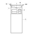
- FIG. 2 shows an example of installing this drive recorder in the vehicle C of an automobile.
- the side mirrors M1 and M2 are located in front of the windshield W (windshield).
- vehicle C is a truck, a bus, or the like without a bonnet.
- the camera 1 is installed on the upper part of the windshield W or the front part of the vehicle on the ceiling of the vehicle so that the fisheye lens 1A faces downward. This makes it possible to photograph the front, left and right of the vehicle, the driver's seat, the passenger's seat, and the like. In addition, a portion higher than the installation height of the camera 1, for example, a traffic light or a sign can be photographed.
- the image processing device 2, the external memory 3, and the monitor 4 can be installed at any place.
- the camera 1 is arranged on a straight line L connecting the driver D (driver's seat) and the side mirror M1 on the opposite side of the driver's seat.
- the camera 1 is arranged on a straight line connecting the left side mirror and the driver's seat.
- the term "on a straight line” means on a straight line connecting the side mirror and the driver's seat when the vehicle C is viewed in a plan view.
- the camera 1 can take a picture of the part that the driver sees with the side mirror, that is, the side mirror that reflects the side part of the vehicle C.
- the side mirror that reflects the side part of the vehicle C.
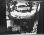
- Figure 3 shows an example of a playback image.
- the side mirror reflects the side portion of the vehicle.
- the driver can easily confirm the state of the side portion of the vehicle.
- the magnification of a necessary part such as a side mirror part may be increased so that it can be displayed on the monitor 4.
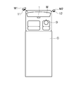
- cameras 11 and 12 having the same configuration as the camera 1 may be installed on the left and right side mirrors M1 and M2 so that the fisheye lens faces downward.
- the captured images of the cameras 11 and 12 are output to the image processing device 2 and stored in the external memory 3 in the same manner as the camera 1.
- the image sensor may be shared by the cameras 1, 11 and 12. That is, the light coming from the three fisheye lenses installed at the center of the vehicle C in the vehicle width direction and at both ends in the vehicle width direction is guided to the same image sensor to receive light, converted into an electric signal, and the image is displayed. It may be generated. As a result, the images taken at the three locations can be treated as completely synchronized images, resulting in an image with higher evidence ability.
- the fisheye lens may be installed at any two locations instead of the three locations at the center of the vehicle C in the vehicle width direction and at both ends in the vehicle width direction.
- cameras 13 and 14 having the same configuration as the camera 1 may be further installed behind the left and right sides of the vehicle C.
- the cameras 13 and 14 are installed at the rear tire positions. As a result, the cause of the accident can be verified more clearly.
- a camera 15 having the same configuration as the camera 1 may be further installed behind the vehicle C.
- an around viewer can be created, and any part can be panned, tilted, zoomed and monitored.
- pan / tilt / zoom it is possible to monitor not only when driving but also when backing up or pulling width, which is useful for driving support.
- the pan / tilt / zoom functions may be provided mechanically or the field of view may be moved by software.
- the vehicle may be decelerated or stopped by analyzing the images taken by one or more cameras and controlling the vehicle speed by automatic braking when there is a person or a foreign object. As a result, an accident can be prevented.
- the present invention is not limited to the above embodiment as it is, and at the implementation stage, the components can be modified and embodied within a range that does not deviate from the gist thereof.
- various inventions can be formed by an appropriate combination of the plurality of constituent elements disclosed in the above-described embodiment. For example, some components may be removed from all the components shown in the embodiments. In addition, components across different embodiments may be combined as appropriate.
Landscapes
- Engineering & Computer Science (AREA)
- Mechanical Engineering (AREA)
- Physics & Mathematics (AREA)
- General Physics & Mathematics (AREA)
- Time Recorders, Dirve Recorders, Access Control (AREA)
- Fittings On The Vehicle Exterior For Carrying Loads, And Devices For Holding Or Mounting Articles (AREA)
- Closed-Circuit Television Systems (AREA)
Applications Claiming Priority (2)
| Application Number | Priority Date | Filing Date | Title |
|---|---|---|---|
| JP2019-067577 | 2019-03-29 | ||
| JP2019067577A JP2020164067A (ja) | 2019-03-29 | 2019-03-29 | ドライブレコーダの設置方法、ドライブレコーダ及び自動車 |
Publications (1)
| Publication Number | Publication Date |
|---|---|
| WO2020204016A1 true WO2020204016A1 (ja) | 2020-10-08 |
Family
ID=72668504
Family Applications (1)
| Application Number | Title | Priority Date | Filing Date |
|---|---|---|---|
| PCT/JP2020/014720 Ceased WO2020204016A1 (ja) | 2019-03-29 | 2020-03-30 | ドライブレコーダの設置方法、ドライブレコーダ及び自動車 |
Country Status (2)
| Country | Link |
|---|---|
| JP (1) | JP2020164067A (enExample) |
| WO (1) | WO2020204016A1 (enExample) |
Families Citing this family (4)
| Publication number | Priority date | Publication date | Assignee | Title |
|---|---|---|---|---|
| JP2024050334A (ja) * | 2022-09-29 | 2024-04-10 | キヤノン株式会社 | 移動体及び撮像装置の設置方法 |
| JP7631275B2 (ja) * | 2022-09-29 | 2025-02-18 | キヤノン株式会社 | 移動体及び撮像装置の設置方法 |
| JP7622025B2 (ja) | 2022-11-30 | 2025-01-27 | キヤノン株式会社 | 画像処理システム、画像処理方法、およびコンピュータプログラム |
| JP2024094614A (ja) * | 2022-12-28 | 2024-07-10 | キヤノン株式会社 | 撮像装置、移動体、及びコンピュータプログラム |
Citations (10)
| Publication number | Priority date | Publication date | Assignee | Title |
|---|---|---|---|---|
| JPS5810232B2 (ja) * | 1974-09-21 | 1983-02-24 | シャープ株式会社 | インクキロクソウチ |
| JP2001045438A (ja) * | 1999-08-04 | 2001-02-16 | Suzuki Motor Corp | 画像処理方法および画像処理装置 |
| JP2005309812A (ja) * | 2004-04-22 | 2005-11-04 | Denso Corp | 車両周辺表示制御装置 |
| JP2007158578A (ja) * | 2005-12-02 | 2007-06-21 | National Univ Corp Shizuoka Univ | 全周囲情報環状表示システム |
| JP2011131740A (ja) * | 2009-12-24 | 2011-07-07 | Kyocera Corp | 車両の運転支援装置 |
| JP2014134912A (ja) * | 2013-01-09 | 2014-07-24 | Fujitsu Ten Ltd | 再生装置、再生システム、再生方法及びプログラム |
| JP2016187273A (ja) * | 2015-03-27 | 2016-10-27 | 京セラ株式会社 | 画像処理装置、撮像装置、排水制御システム、および車両 |
| JP2017045396A (ja) * | 2015-08-28 | 2017-03-02 | 富士通テン株式会社 | 画像記録装置および画像記録方法 |
| JP2017201789A (ja) * | 2017-06-02 | 2017-11-09 | 富士通テン株式会社 | 画像処理装置、表示装置、携帯用表示装置、画像処理方法、表示装置の表示方法、携帯用表示装置の表示方法及びプログラム |
| JP2018107620A (ja) * | 2016-12-26 | 2018-07-05 | 京セラ株式会社 | 撮像システム、移動体、および制御方法 |
Family Cites Families (5)
| Publication number | Priority date | Publication date | Assignee | Title |
|---|---|---|---|---|
| JP4797603B2 (ja) * | 2005-11-29 | 2011-10-19 | トヨタ自動車株式会社 | 運転支援装置 |
| JP5786901B2 (ja) * | 2013-06-20 | 2015-09-30 | 株式会社デンソー | 事故通報システム |
| JP5810232B1 (ja) * | 2014-03-28 | 2015-11-11 | 富士重工業株式会社 | 車両用制御装置 |
| JP6892258B2 (ja) * | 2016-12-15 | 2021-06-23 | 株式会社東芝 | 運転状態制御装置および運転状態制御方法 |
| JP2018138433A (ja) * | 2017-02-24 | 2018-09-06 | 株式会社デンソーテン | 車両用歩行者保護装置 |
-
2019
- 2019-03-29 JP JP2019067577A patent/JP2020164067A/ja active Pending
-
2020
- 2020-03-30 WO PCT/JP2020/014720 patent/WO2020204016A1/ja not_active Ceased
Patent Citations (10)
| Publication number | Priority date | Publication date | Assignee | Title |
|---|---|---|---|---|
| JPS5810232B2 (ja) * | 1974-09-21 | 1983-02-24 | シャープ株式会社 | インクキロクソウチ |
| JP2001045438A (ja) * | 1999-08-04 | 2001-02-16 | Suzuki Motor Corp | 画像処理方法および画像処理装置 |
| JP2005309812A (ja) * | 2004-04-22 | 2005-11-04 | Denso Corp | 車両周辺表示制御装置 |
| JP2007158578A (ja) * | 2005-12-02 | 2007-06-21 | National Univ Corp Shizuoka Univ | 全周囲情報環状表示システム |
| JP2011131740A (ja) * | 2009-12-24 | 2011-07-07 | Kyocera Corp | 車両の運転支援装置 |
| JP2014134912A (ja) * | 2013-01-09 | 2014-07-24 | Fujitsu Ten Ltd | 再生装置、再生システム、再生方法及びプログラム |
| JP2016187273A (ja) * | 2015-03-27 | 2016-10-27 | 京セラ株式会社 | 画像処理装置、撮像装置、排水制御システム、および車両 |
| JP2017045396A (ja) * | 2015-08-28 | 2017-03-02 | 富士通テン株式会社 | 画像記録装置および画像記録方法 |
| JP2018107620A (ja) * | 2016-12-26 | 2018-07-05 | 京セラ株式会社 | 撮像システム、移動体、および制御方法 |
| JP2017201789A (ja) * | 2017-06-02 | 2017-11-09 | 富士通テン株式会社 | 画像処理装置、表示装置、携帯用表示装置、画像処理方法、表示装置の表示方法、携帯用表示装置の表示方法及びプログラム |
Also Published As
| Publication number | Publication date |
|---|---|
| JP2020164067A (ja) | 2020-10-08 |
Similar Documents
| Publication | Publication Date | Title |
|---|---|---|
| WO2020204016A1 (ja) | ドライブレコーダの設置方法、ドライブレコーダ及び自動車 | |
| JP5194679B2 (ja) | 車両用周辺監視装置および映像表示方法 | |
| KR101766077B1 (ko) | 차량 주변 영상 정보 제공 시스템 및 방법 | |
| US8736680B1 (en) | Method and system for split-screen video display | |
| WO2018030285A1 (ja) | 複数カメラを用いた車両用モニタリングシステム | |
| JP2000225970A (ja) | 車載用画像記録システム | |
| CN101585347B (zh) | 汽车后视系统及具有该后视系统的汽车 | |
| WO2010050012A1 (ja) | 車載用カメラモジュール | |
| JP2007313950A (ja) | 車両監視装置 | |
| CN102474597A (zh) | 车辆周围图像生成装置 | |
| JPWO2020090511A1 (ja) | 撮影装置、画像処理方法、及び、プログラム | |
| US20140176699A1 (en) | Driving assistant system and method | |
| JP7622025B2 (ja) | 画像処理システム、画像処理方法、およびコンピュータプログラム | |
| US20140184737A1 (en) | Driving assistant system and method | |
| JP2023046953A (ja) | 画像処理システム、移動装置、画像処理方法、およびコンピュータプログラム | |
| JPH05310078A (ja) | 車両安全確認装置及びその装置に使用するカメラ | |
| JP2011124879A (ja) | 車両用撮像システム及び車載用撮像装置 | |
| JP2023046511A (ja) | 画像処理システム、画像処理方法、およびコンピュータプログラム | |
| JP4606322B2 (ja) | 車両運転支援装置 | |
| JP2000247265A (ja) | 車載用画像記録システム | |
| WO2020003630A1 (ja) | 画像処理装置、画像処理方法、ドライブレコーダー | |
| JP7348323B2 (ja) | 電子ミラーの映像合成装置及び映像合成方法 | |
| KR100593594B1 (ko) | 파노라마 카메라를 포함하는 차량 주행 보조 장치 | |
| CN115633153B (zh) | 摄像装置 | |
| JP3147679B2 (ja) | 車両用周辺視認装置 |
Legal Events
| Date | Code | Title | Description |
|---|---|---|---|
| 121 | Ep: the epo has been informed by wipo that ep was designated in this application |
Ref document number: 20782460 Country of ref document: EP Kind code of ref document: A1 |
|
| NENP | Non-entry into the national phase |
Ref country code: DE |
|
| 122 | Ep: pct application non-entry in european phase |
Ref document number: 20782460 Country of ref document: EP Kind code of ref document: A1 |