WO2020203994A1 - ガス分離システム - Google Patents
ガス分離システム Download PDFInfo
- Publication number
- WO2020203994A1 WO2020203994A1 PCT/JP2020/014656 JP2020014656W WO2020203994A1 WO 2020203994 A1 WO2020203994 A1 WO 2020203994A1 JP 2020014656 W JP2020014656 W JP 2020014656W WO 2020203994 A1 WO2020203994 A1 WO 2020203994A1
- Authority
- WO
- WIPO (PCT)
- Prior art keywords
- gas
- gas separation
- separation membrane
- membrane unit
- permeated
- Prior art date
- Legal status (The legal status is an assumption and is not a legal conclusion. Google has not performed a legal analysis and makes no representation as to the accuracy of the status listed.)
- Ceased
Links
Images
Classifications
-
- C—CHEMISTRY; METALLURGY
- C10—PETROLEUM, GAS OR COKE INDUSTRIES; TECHNICAL GASES CONTAINING CARBON MONOXIDE; FUELS; LUBRICANTS; PEAT
- C10L—FUELS NOT OTHERWISE PROVIDED FOR; NATURAL GAS; SYNTHETIC NATURAL GAS OBTAINED BY PROCESSES NOT COVERED BY SUBCLASSES C10G OR C10K; LIQUIFIED PETROLEUM GAS; USE OF ADDITIVES TO FUELS OR FIRES; FIRE-LIGHTERS
- C10L3/00—Gaseous fuels; Natural gas; Synthetic natural gas obtained by processes not covered by subclass C10G, C10K; Liquefied petroleum gas
- C10L3/06—Natural gas; Synthetic natural gas obtained by processes not covered by C10G, C10K3/02 or C10K3/04
- C10L3/10—Working-up natural gas or synthetic natural gas
-
- B—PERFORMING OPERATIONS; TRANSPORTING
- B01—PHYSICAL OR CHEMICAL PROCESSES OR APPARATUS IN GENERAL
- B01D—SEPARATION
- B01D53/00—Separation of gases or vapours; Recovering vapours of volatile solvents from gases; Chemical or biological purification of waste gases, e.g. engine exhaust gases, smoke, fumes, flue gases, aerosols
- B01D53/22—Separation of gases or vapours; Recovering vapours of volatile solvents from gases; Chemical or biological purification of waste gases, e.g. engine exhaust gases, smoke, fumes, flue gases, aerosols by diffusion
- B01D53/225—Multiple stage diffusion
- B01D53/226—Multiple stage diffusion in serial connexion
-
- B—PERFORMING OPERATIONS; TRANSPORTING
- B01—PHYSICAL OR CHEMICAL PROCESSES OR APPARATUS IN GENERAL
- B01D—SEPARATION
- B01D63/00—Apparatus in general for separation processes using semi-permeable membranes
- B01D63/02—Hollow fibre modules
-
- B—PERFORMING OPERATIONS; TRANSPORTING
- B01—PHYSICAL OR CHEMICAL PROCESSES OR APPARATUS IN GENERAL
- B01D—SEPARATION
- B01D69/00—Semi-permeable membranes for separation processes or apparatus characterised by their form, structure or properties; Manufacturing processes specially adapted therefor
- B01D69/08—Hollow fibre membranes
-
- B—PERFORMING OPERATIONS; TRANSPORTING
- B01—PHYSICAL OR CHEMICAL PROCESSES OR APPARATUS IN GENERAL
- B01D—SEPARATION
- B01D71/00—Semi-permeable membranes for separation processes or apparatus characterised by the material; Manufacturing processes specially adapted therefor
- B01D71/06—Organic material
- B01D71/58—Other polymers having nitrogen in the main chain, with or without oxygen or carbon only
- B01D71/62—Polycondensates having nitrogen-containing heterocyclic rings in the main chain
- B01D71/64—Polyimides; Polyamide-imides; Polyester-imides; Polyamide acids or similar polyimide precursors
- B01D71/641—Polyamide-imides
-
- B—PERFORMING OPERATIONS; TRANSPORTING
- B01—PHYSICAL OR CHEMICAL PROCESSES OR APPARATUS IN GENERAL
- B01D—SEPARATION
- B01D71/00—Semi-permeable membranes for separation processes or apparatus characterised by the material; Manufacturing processes specially adapted therefor
- B01D71/06—Organic material
- B01D71/58—Other polymers having nitrogen in the main chain, with or without oxygen or carbon only
- B01D71/62—Polycondensates having nitrogen-containing heterocyclic rings in the main chain
- B01D71/64—Polyimides; Polyamide-imides; Polyester-imides; Polyamide acids or similar polyimide precursors
- B01D71/643—Polyether-imides
-
- C—CHEMISTRY; METALLURGY
- C10—PETROLEUM, GAS OR COKE INDUSTRIES; TECHNICAL GASES CONTAINING CARBON MONOXIDE; FUELS; LUBRICANTS; PEAT
- C10L—FUELS NOT OTHERWISE PROVIDED FOR; NATURAL GAS; SYNTHETIC NATURAL GAS OBTAINED BY PROCESSES NOT COVERED BY SUBCLASSES C10G OR C10K; LIQUIFIED PETROLEUM GAS; USE OF ADDITIVES TO FUELS OR FIRES; FIRE-LIGHTERS
- C10L3/00—Gaseous fuels; Natural gas; Synthetic natural gas obtained by processes not covered by subclass C10G, C10K; Liquefied petroleum gas
- C10L3/06—Natural gas; Synthetic natural gas obtained by processes not covered by C10G, C10K3/02 or C10K3/04
- C10L3/10—Working-up natural gas or synthetic natural gas
- C10L3/101—Removal of contaminants
- C10L3/102—Removal of contaminants of acid contaminants
- C10L3/104—Carbon dioxide
-
- B—PERFORMING OPERATIONS; TRANSPORTING
- B01—PHYSICAL OR CHEMICAL PROCESSES OR APPARATUS IN GENERAL
- B01D—SEPARATION
- B01D53/00—Separation of gases or vapours; Recovering vapours of volatile solvents from gases; Chemical or biological purification of waste gases, e.g. engine exhaust gases, smoke, fumes, flue gases, aerosols
- B01D53/22—Separation of gases or vapours; Recovering vapours of volatile solvents from gases; Chemical or biological purification of waste gases, e.g. engine exhaust gases, smoke, fumes, flue gases, aerosols by diffusion
- B01D2053/221—Devices
- B01D2053/223—Devices with hollow tubes
- B01D2053/224—Devices with hollow tubes with hollow fibres
-
- B—PERFORMING OPERATIONS; TRANSPORTING
- B01—PHYSICAL OR CHEMICAL PROCESSES OR APPARATUS IN GENERAL
- B01D—SEPARATION
- B01D2256/00—Main component in the product gas stream after treatment
- B01D2256/24—Hydrocarbons
- B01D2256/245—Methane
-
- B—PERFORMING OPERATIONS; TRANSPORTING
- B01—PHYSICAL OR CHEMICAL PROCESSES OR APPARATUS IN GENERAL
- B01D—SEPARATION
- B01D2257/00—Components to be removed
- B01D2257/50—Carbon oxides
- B01D2257/504—Carbon dioxide
-
- B—PERFORMING OPERATIONS; TRANSPORTING
- B01—PHYSICAL OR CHEMICAL PROCESSES OR APPARATUS IN GENERAL
- B01D—SEPARATION
- B01D2317/00—Membrane module arrangements within a plant or an apparatus
- B01D2317/02—Elements in series
- B01D2317/025—Permeate series
-
- C—CHEMISTRY; METALLURGY
- C10—PETROLEUM, GAS OR COKE INDUSTRIES; TECHNICAL GASES CONTAINING CARBON MONOXIDE; FUELS; LUBRICANTS; PEAT
- C10L—FUELS NOT OTHERWISE PROVIDED FOR; NATURAL GAS; SYNTHETIC NATURAL GAS OBTAINED BY PROCESSES NOT COVERED BY SUBCLASSES C10G OR C10K; LIQUIFIED PETROLEUM GAS; USE OF ADDITIVES TO FUELS OR FIRES; FIRE-LIGHTERS
- C10L2290/00—Fuel preparation or upgrading, processes or apparatus therefore, comprising specific process steps or apparatus units
- C10L2290/54—Specific separation steps for separating fractions, components or impurities during preparation or upgrading of a fuel
- C10L2290/548—Membrane- or permeation-treatment for separating fractions, components or impurities during preparation or upgrading of a fuel
Definitions
- the present invention relates to a gas separation system for producing a CH 4- enriched gas from a raw material gas containing carbon dioxide (CO 2 ) and methane (CH 4 ) using a plurality of gas separation membrane units.
- a membrane separation method using the difference in permeation rate of these gases with respect to the membrane is known.
- a high-purity CH 4- enriched gas which is a target gas, can be obtained by recovering the non-permeated gas.
- Permeation rate is a transmission volume per unit membrane area and unit time and a unit partial pressure difference with respect to the film of the CO 2 and CH 4 contained in the raw material gas, P 'CO2 and P' CH4 (unit, ⁇ 10 -5 cm 3 (STP) can be expressed by / (cm 2 ⁇ sec ⁇ cmHg )).
- the gas separation selectivity of the CO 2 and CH 4 films can be expressed by the ratio of these permeation rates, P'CO2 / P'CH4 (permeation rate of high-permeability gas / permeation rate of low-permeability gas). ..
- the gas separation membrane is used as a gas separation membrane module in which a gas separation membrane having gas selective permeability is housed in a container provided with at least a gas inlet, a permeated gas discharge port, and a non-permeated gas discharge port. Has been done.
- the gas separation membrane is installed in the container so that the space on the gas supply side and the space on the gas permeation side are separated.
- it is generally used as a gas separation membrane unit in which a plurality of gas separation membrane modules are combined in parallel in order to obtain a required membrane area.
- the gas separation membrane unit Since the plurality of gas separation membrane modules constituting the gas separation membrane unit share the gas inlet, the impermeable gas discharge port, and the permeation gas discharge port, the gas separation membrane unit is a gas separation membrane module having a substantially large membrane area. Acts as.
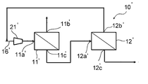
- a two-stage separation system 10'as shown in FIG. has been used conventionally.
- the system 10'in FIG. 3 is a gas separation system including two gas separation membrane units 11'and 12'.
- the mixed gas as a raw material is supplied to the first gas separation membrane unit 11', and the non-permeated gas from the first gas separation membrane unit 11'is supplied to the second gas separation membrane unit 12'.
- the non-permeated gas supplied from the second gas separation membrane unit 12' is recovered as a product gas.
- the permeated gas from the second gas separation membrane unit 12' merges with the raw material gas again and is supplied to the first gas separation membrane unit 11'.
- a two-stage gas separation system that separates the permeated gas of the first gas separation membrane unit in the second stage has also been proposed in the application of extracting the permeated gas as a product gas (Patent Document 1). ).
- an object of the present invention is to provide a gas separation system that can eliminate the drawbacks of the above-mentioned prior art.
- the present invention is a gas separation system including a first gas separation membrane unit and a second gas separation membrane unit, which is used for producing CH 4- enriched gas from a raw material gas containing CO 2 and CH 4 .
- Each gas separation membrane unit includes at least a gas inlet, a permeated gas outlet and a non-permeated gas outlet.
- the raw material gas supply line connected to the gas inlet of the first gas separation membrane unit,
- the compression means placed in the raw material gas supply line and A first connecting line that connects the permeated gas discharge port of the first gas separation membrane unit and the gas inlet of the second gas separation membrane unit, It has a second connecting line that connects the impermeable gas discharge port of the second gas separation membrane unit and the raw material gas supply line.
- the gas separation selectivity P'CO2 / P'CH4 of the first gas separation membrane unit and the second gas separation membrane unit is 30 or more.
- the recovery rate of CH 4 is 98% or more, the CO 2 content in the impermeable gas discharged from the impermeable gas discharge port of the first gas separation membrane unit is 5 mol% or less, and the second gas separation is performed.
- a gas separation system in which the amount of gas supplied to the membrane unit per hour is 60% or less of the amount of raw material gas supplied to the first gas separation membrane unit per hour. ..
- the present invention is a method for producing CH 4- enriched gas from a raw material gas containing CO 2 and CH 4 using a gas separation system.
- a gas separation system Equipped with a first gas separation membrane unit and a second gas separation membrane unit, Each gas separation membrane unit includes at least a gas inlet, a permeated gas outlet and a non-permeated gas outlet.
- the raw material gas supply line connected to the gas inlet of the first gas separation membrane unit, A compression means intervening in the raw material gas supply line, A first connecting line that connects the permeated gas discharge port of the first gas separation membrane unit and the gas inlet of the second gas separation membrane unit, It has a second connecting line that connects the impermeable gas discharge port of the second gas separation membrane unit and the raw material gas supply line.
- the recovery rate of CH 4 is 98% or more, the CO 2 content in the impermeable gas discharged from the impermeable gas discharge port of the first gas separation membrane unit is 5 mol% or less, and the first gas separation is performed.
- a method for producing CH 4- enriched gas in which the gas separation system is operated so that the amount of permeated gas per hour of the membrane unit is 60% or less of the amount of raw material gas per hour supplied to the first gas separation membrane unit. Is to provide.
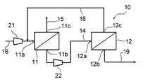
- FIG. 1 is a schematic view showing the configuration of a gas separation system for methane separation according to an embodiment of the present invention.
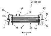
- FIG. 2 is a schematic view showing the structure of an example of a module constituting the gas separation membrane unit used in the gas separation system of the present invention.
- FIG. 3 is a schematic view showing the configuration of a conventional gas separation system for methane separation.
- the gas separation system 10 which is a preferred embodiment of the present invention and a preferred embodiment of the present invention for producing a CH 4- enriched gas using the gas separation system 10 will be described.
- the gas separation system 10 of the present embodiment includes two gas separation membrane units, a first gas separation membrane unit 11 and a second gas separation membrane unit 12.
- a module 40 having a gas separation membrane 30 made of a hollow fiber membrane or the like and having gas selective permeability is housed in a casing 31 is used. Can be done.
- the permeation rate of CO 2 is P'CO2 (cm 3 (STP) / (cm 2 ⁇ sec ⁇ cmHg)) and the permeation rate of CH 4 is P'CH4 (cm). is higher than the 3 (STP) / (cm 2 ⁇ sec ⁇ cmHg)).
- Each of the gas separation membrane units 11 and 12 of the present embodiment uses one gas separation membrane module 40 shown in FIG. 2, or a plurality of these modules 40 are arranged in parallel.
- the casing 31 in the module 40 has two facing surfaces open to form an opening 32.
- the opening 32 is for inserting the gas separation membrane 30 into the casing 31, not the opening of the gas separation membrane 30.
- the gas separation membrane 30 is housed in the casing 31 through the opening 32.
- the gas separation membrane 30 is composed of a bundle of hollow fiber membranes in which a large number of hollow fiber membranes are bundled so as to coincide with each other in the longitudinal direction, the gas separation membrane 30 is in the accommodation state, and each opening 32 of the casing 31 is formed. It is housed in the casing 31 so that each end of the hollow fiber membrane opens in the vicinity of.
- the gas separation membrane 30 In the state where the gas separation membrane 30 is housed in the casing 31, the gas separation membrane 30 is fixed to the inner wall of the casing 31 by the tube plates 33 and 34 at the positions of both ends in the Y direction, which is the extending direction of the hollow fiber membrane. Has been done.
- Each opening 32 of the casing 31 is closed by lids 35 and 36.
- the lid 35 is provided with a gas inlet 37.
- the lid 36 is provided with a non-permeated gas discharge port 38.
- the mixed gas to be separated is introduced into the module (that is, the unit) from the gas inlet 37 of the lid 35.
- the gas that has permeated through the gas separation membrane 30 is discharged to the outside of the module (that is, outside the unit) from the permeation gas discharge port 39 provided in the casing 31.
- the impermeable gas that has not permeated through the gas separation membrane 30 is discharged to the outside of the module (that is, outside the unit) from the impermeable gas discharge port 38 of the lid 36.
- the casing 31 may be provided with a purge gas supply port (not shown).
- first gas separation membrane unit 11 and the second gas separation membrane unit 12 are connected in series. Specifically, the first gas separation membrane unit 11 and the second gas separation membrane unit 12 are the permeation gas discharge port 11b of the first gas separation membrane unit 11 and the gas inlet 12a of the second gas separation membrane unit 12. Is connected by connecting with the first connecting line 14.
- a raw material gas supply line 16 for supplying a raw material gas from a mixed gas source (not shown) as a raw material to the first gas separation membrane unit 11 is connected to the gas inlet 11a of the first gas separation membrane unit 11.
- a second connecting line 18 for supplying the non-permeable gas of the second gas separation membrane unit 12 to the first gas separation membrane unit 11 is connected to the non-permeable gas discharge port 12c of the second gas separation membrane unit 12.
- the second connecting line 18 may be connected to either the discharge side or the suction side of the first compression means 21 in the raw material gas supply line 16, but from the viewpoint of suppressing the required compression power of the system, the second connection line 18 may be connected to the discharge side. It is preferable that they are connected.
- the first compression means 21 is interposed in the middle of the raw material gas supply line 16.
- the first compression means 21 is installed for the purpose of pressurizing the raw material gas and supplying it to the first gas separation membrane unit 11.
- the second compression means 22 is interposed and arranged in the middle of the first connection line 14.
- the second means 22 is installed for the purpose of pressurizing the permeated gas discharged from the permeated gas discharge port 11b of the first gas separation membrane unit 11 and supplying it to the second gas separation membrane unit 12.
- a compressor can be used as the first compression means 21 and the second compression means 22.
- the system 10 is connected to the non-permeable gas discharge port 11c of the first gas separation membrane unit 11, and has a first take-out line 15 for taking out the non-permeable gas from the discharge port 11c to the outside of the system, and a second gas separation membrane unit. It is connected to the permeated gas discharge port 12b of 12, and has a second take-out line 19 for taking out the permeated gas from the discharge port 12b to the outside of the system.
- the raw material gas to be separated is supplied from the mixed gas source (not shown) to the first gas separation membrane unit 11 through the raw material gas supply line 16.
- the raw material gas contains at least CO 2 and CH 4 to be separated.
- the permeated gas which is the gas that has permeated the gas separation membrane, and the gas are separated due to the difference in the permeation rate with respect to the gas separation membrane. It is separated into a non-permeated gas, which is a gas that has not permeated the membrane.
- any gas separation membrane of the first gas separation membrane unit 11 and the second gas separation membrane unit 12 has a larger CO2 'permeation rate P of CO 2 compared to CH4' permeation rate P of CH 4 ..
- the non-permeated gas discharged from the non-permeated gas discharge port 11c of the first gas separation membrane unit 11 is one in which CH 4 is concentrated as compared with the raw material gas.
- the non-permeated gas is discharged from the non-permeated gas discharge port 11c and is taken out of the system through the first take-out gas line 15.
- the permeated gas from the first gas separation membrane unit 11 is one in which CO 2 is concentrated as compared with the raw material gas.
- the permeated gas is discharged from the permeated gas discharge port 11b, supplied to the second gas separation membrane unit 12 through the first connecting line 14, and further discharged from the permeated gas discharge port 12b of the second gas separation membrane unit 12.
- the carbon-enriched gas is taken out of the system.
- the non-permeated gas of the second gas separation membrane unit 12 passes through the second connecting line 18 again from the non-permeated gas discharge port 12c, is introduced into the raw material gas supply line 16, and merges with the raw material gas to be the first gas. It is supplied to the separation membrane unit 11.
- the CO 2 content in the impermeable gas discharged from the impermeable gas discharge port 11c of the first gas separation membrane unit 11 is 5 mol% or less. Further, in order to increase the purity of CH 4 in the non-permeated gas, the CO 2 content in the non-permeated gas is particularly preferably 3 mol% or less.
- the CH 4 purity in the non-permeated gas is preferably 95 mol% or more, more preferably 97 mol% or more.
- the recovery rate of CH 4 is 98% or more, and it is particularly preferable that it is 98.5% or more.
- Recovery of CH 4 is discharged per unit time from the non-permeate gas outlet 11c of the first gas separation membrane unit 11 to the amount of CH 4 in the raw material gas per unit time is introduced into the first gas separation membrane unit 11 It is calculated as the amount of CH 4 in the non-permeated gas.
- the recovery rate is a ratio based on the volume in the standard state.
- CH 4 is a greenhouse gas. Recovery is preferably low from the viewpoint of membrane area and energy consumption, high recovery is desired in order to suppress the loss of CH 4 gas.
- the gas supplied to the first gas separation membrane unit 11 has a flow rate (F2) (gas amount per hour, unit Nm 3 / h) of the gas supplied to the second gas separation membrane unit 12.
- the ratio to the flow rate (F1) (hereinafter, also referred to as “supply flow rate ratio (F2 / F1)”) is set to 60% or less.
- the supply flow rate of the second gas separation membrane unit 12 is set to a certain level or less, the flow rate of the entire system that depends on this flow rate is suppressed, and the entire system that depends on the flow rate is compressed. Power can be suppressed.
- the compression power of the second compression means 22 can be significantly reduced.
- the supply flow rate ratio (F2 / F1) is more preferably 50% or less. The lower the supply flow rate ratio (F2 / F1), the better, but usually it is 10% or more or 20% or more.
- the gas separation selectivity P'CO2 / P'CH4 is a specific value for each of the first gas separation membrane unit 11 and the second gas separation membrane unit 12.
- Gas separation selectivity (P 'CO2 / P' CH4 ) 1 and the gas separation selectivity of the second gas separation membrane unit 12 (P 'CO2 / P' CH4) 2 of specifically the first gas separation membrane unit 11 All of them are 30 or more, which means that the compression power of the second compression means 22 can be reduced, and the film area can be reduced and the compression power can be suppressed at the same time while reducing the amount of CO 2 gas in the product gas.
- Gas separation selectivity (P 'CO2 / P' CH4 ) 1 and the gas separation selectivity of the second gas separation membrane unit 12 (P 'CO2 / P' CH4) 2 of the first gas separation membrane unit 11 is 35 or more Is more preferable.
- Gas separation selectivity (P 'CO2 / P' CH4 ) 1 and the gas separation selectivity of the second gas separation membrane unit 12 (P 'CO2 / P' CH4) 2 of the first gas separation membrane unit 11 is generally 120 or less Is preferable from the viewpoint of ease of manufacturing the gas separation membrane unit.
- the ratio of the membrane area S1 of the first gas separation membrane unit 11 to the membrane area S2 of the second gas separation membrane unit is preferably S1 / S2 of 1 or more and 14 or less because F2 / F1 can easily be in the above range. More preferably, it is 2 or more and 12 or less.
- constitutes two units gas separation selectivity of the first gas separation membrane units 11 (P 'CO2 / P' CH4) 1 and the gas separation selectivity of the second gas separation membrane unit 12 (P 'CO2 / P'CH4 ) 2 may be the same or different.
- the 'transmission rate P of CO 2 CO2 1 and the second gas separation membrane unit 12' CH4 2 first gas separation membrane unit 11 permeation rate P of CO 2 may be different may be the same.
- permeation rate P of the CO 2 of the first gas separation membrane unit 'CO2 1 is permeation rate P of the CO 2 gas separation membrane used in the second gas separation membrane unit' higher than the CO2 2, the system It is preferable in that the number of membrane modules can be reduced without significantly impairing the overall efficiency.
- the ratio of the permeation rates of both P'CO2 2 / P'CO2 1 is preferably 0.7 or less, more preferably 0.5 or less.
- Aforementioned gas separation selectivity P 'CO2 / P' CH4 ( P 'CO2 / P' CH4 1 and P 'CO2 / P' CH4 2 ) and permeation rate P of CO 2 'CO2 (P' CO2 1 and P 'CO2 2), respectively, it may be a permeation rate P 'CO2 gas separation selectivity P' CO2 / P 'CH4 and CO 2 in the temperature conditions in the gas separation membrane unit during operation.
- the gas permeation rate may be lower than when the operating temperature is set relatively high.
- the operating temperature of each unit may be different, and the permeation speed between the two units may be the above-mentioned relationship.
- the operating temperature of the second gas separation membrane unit 12 is made higher than that of the first gas separation membrane unit 11, and the permeation rate of CO 2 of the first gas separation membrane unit 11 is higher than that of P'CO2 1.
- the P'CO2 2 of the unit 12 may be increased.
- the operating temperature of the first gas separation membrane unit 11 is made higher than that of the second gas separation membrane unit 12, and the permeation rate of CO 2 of the second gas separation membrane unit 12 is higher than that of P'CO2 2.
- the P'CO2 1 of the unit 11 may be increased.
- the difference in operating temperature is preferably 5 ° C. or higher, more preferably 20 ° C. or higher, and particularly preferably 40 ° C. or higher.
- the operating temperature of the first gas separation membrane unit 11 and the second gas separation membrane unit is not particularly limited, and is, for example, room temperature or higher and 80 ° C. or lower.
- Gas separation selectivity of the first gas separation membrane unit 11 ( P'CO2 / P'CH4 ) 1 and gas separation selectivity of the second gas separation membrane unit 12 ( P'CO2 / P'CH4 ) 2 ratio (P' CO2 / P 'CH4) 1 / (P' CO2 / P 'CH4) 2 is preferably to increase the CH 4 recovery rate while suppressing module number, for example 0.2 to 1.1, It is more preferably 0.2 or more and 1 or less.
- the gas separation system and gas separation method of the present invention include, for example, 40 volumes of CH 4 in a total of 100% by volume of CH 4 and CO 2. It can be used for separating a raw material gas or the like having a CO 2 content of 20% by volume or more and 60% by volume or less.
- carbon dioxide (CO 2) and methane (CH 4) is carbon dioxide (CO 2) volume ratio of the well be larger than methane (CH 4), the volume ratio of carbon dioxide (CO 2) It may be smaller than methane (CH 4 ).
- the total ratio of CH 4 and CO 2 in the raw material gas is preferably 95% by volume or more, and more preferably 98% by volume or more.
- Biogas refers to a gas generated by methane fermentation of organic waste by the action of anaerobic microorganisms.
- biogas include digestion gas generated by anaerobic fermentation of sewage sludge and landfill gas generated from a landfill site for waste.
- organic waste include the above-mentioned sewage sludge and landfill waste, manure from dairy cows and pigs, and food residues.
- the raw material gas is natural gas because the gas separation system of the present invention can be preferably used.
- the gas separation membranes in the gas separation membrane units 11 and 12 can be appropriately selected according to the type of mixed gas to be supplied and the target product gas.
- the gas separation membrane the same ones used so far in the technical field can be used without particular limitation. Examples thereof include rubber-like polymer materials such as silicone resin and polybutadiene resin, glassy polymer materials such as polyimide, polyetherimide, polyamide, polyamideimide, polysulfone, polycarbonate and cellulose, and ceramic materials such as zeolite.
- the gas separation membrane may be a homogeneous membrane, an asymmetric membrane composed of a homogeneous layer and a porous layer, a microporous membrane, or the like.
- the form of storing the gas separation membrane in the casing may be any of a plate-and-frame type, a spiral type, a hollow fiber type and the like.
- a particularly preferably used gas separation membrane is a hollow fiber gas separation membrane of aromatic polyimide.
- the hollow fiber gas separation membrane preferably has an asymmetric structure in which the thickness of the homogeneous layer is 10 nm or more and 200 nm or less, and the thickness of the porous layer is 20 ⁇ m or more and 200 ⁇ m or less.
- the inner diameter of the hollow fiber membrane is preferably about 30 ⁇ m or more and 500 ⁇ m or less.
- the number of gas separation membrane modules provided in one gas separation membrane unit may be one or a plurality. When two or more gas separation membrane modules are provided in one gas separation membrane unit, it is preferable that they are connected in parallel in the unit. When each gas separation membrane unit includes a plurality of gas separation membrane modules, the membrane area in the unit can be easily adjusted by changing the number of the gas separation membrane modules.
- the pressure of the gas sent to the first gas separation membrane unit 11 and the second gas separation membrane unit 12 made of the hollow fiber membrane is 0.2 MPaG to 2.0 MPaG. It is preferable that the pressure of the gas sent to the second gas separation membrane unit 12 is slightly higher (about 0 to 0.3 MPaG) than the pressure of the gas sent to the first gas separation membrane unit 11.
- the present invention has been described above based on the preferred embodiment, the present invention is not limited to the above embodiment.
- the second compression means 22 is interposed in the first connecting line 14.
- the compression power can be further reduced. preferable.
- a gas separation membrane unit having a hollow fiber membrane is used as an example of each gas separation membrane unit, but a gas separation membrane unit of another form may be used instead.
- Examples 1-1 to 1-5 The mixed gas containing carbon dioxide and methane was separated using the gas separation system 10 shown in FIG. A compressor was used as the first compression means 21 in the system 10. Gas mixture composition used was the CO 2 40 vol%, CH 4 60% by volume. As modules constituting the first and second gas separation membrane unit 11, 12, P 'CO2 is 9.62 ⁇ 10 -5 cm 3 (STP ) / (cm 2 ⁇ sec ⁇ cmHg), P' CH4 is 0.
- a gas separation selectivity P 'CO2 / P' CH4 is 61.91
- a gas separation membrane composed of polyimide hollow fiber membranes A plurality of gas separation membrane modules housed in the case were connected in parallel and used.
- the operating temperature of the first and second gas separation membrane units 11 and 12 was 35 ° C.
- the number of gas separation membrane modules constituting the first gas separation membrane unit 11 was set to 70, and the number of gas separation membrane modules constituting the second gas separation membrane unit 12 was set to the value shown in Table 1.
- the mixed gas is supplied to the first gas separation membrane unit 11 at a flow rate of 500 Nm 3 / h and a pressure of 1 MPaG, and the permeated gas of the first gas separation membrane unit 11 is supplied to the second gas separation membrane unit 11 at a pressure of 1.1 MPaG. It was supplied to the unit 12 and the non-permeated gas of the second gas separation membrane unit 12 was returned to the first gas separation membrane unit 11.
- the permeated gas pressure at the permeated gas discharge port of the first gas separation membrane unit 11 and the permeated gas pressure at the permeated gas discharge port of the second gas separation membrane unit 12 were 0.03 MPaG. Under these conditions, the supply flow rate to each unit is shown in Table 1. Further, the composition of the non-permeated gas of the first gas separation membrane unit 11, the recovery rate of CH 4 (Rcv.,%), The flow rate of the permeated gas and the non-permeated gas of each unit, the supply flow rate ratio (F2 / F1), and the first 2 Table 1 shows the compression power of the compression means 22 and the total compression power (sum of the compression powers of the compression means 21 and 22).
- Examples 2-1 to 2-5 Examples except that the number of gas separation membrane modules of the first gas separation membrane unit 11 is set to 80 and the number of gas separation membrane modules constituting the second gas separation membrane unit 12 is set to the value shown in Table 1. It was the same as 1-1.
- Table 1 shows the supply flow rate to each unit. Further, the composition of the non-permeated gas of the first gas separation membrane unit 11, the recovery rate of CH 4 (Rcv.,%), The flow rate of the permeated gas and the non-permeated gas of each unit, the supply flow rate ratio (F2 / F1), the first. 2 Table 1 shows the compression power and the total compression power of the compression means 22.
- Examples 3-1 to 3-6 As modules constituting the first gas separation membrane unit 11 and the second gas separation membrane unit 12, P'CO2 is 8.49 ⁇ 10-5 cm 3 (STP) / (cm 2 ⁇ sec ⁇ cmHg), P'CH4. There 0.16 ⁇ 10 -5 cm 3 (STP ) / (cm 2 ⁇ sec ⁇ cmHg), a gas separation selectivity P 'CO2 / P' CH4 is 54.63, the gas composed of the polyimide hollow fiber membranes A plurality of gas separation membrane modules for accommodating the separation membrane in the case were connected in parallel and used. Except for these points, the same as in Example 2-1.
- the number of gas separation membrane modules of the first gas separation membrane unit 11 and the second gas separation membrane unit 12 was set to the number shown in Table 2. Except for these points, the same as in Example 1-1.
- Table 2 shows the supply flow rate to each unit. Further, the composition of the non-permeated gas of the first gas separation membrane unit 11, the recovery rate of CH 4 (Rcv.,%), The flow rate of the permeated gas and the non-permeated gas of each unit, the supply flow rate ratio (F2 / F1), the first. 2 Table 2 shows the compression power and the total compression power of the compression means 22.
- the number of gas separation membrane modules constituting the first gas separation membrane unit 11' was set to the values shown in Table 3.
- the number of gas separation membrane modules constituting the second gas separation membrane unit 12' was set to 70.
- the mixed gas is supplied to the first gas separation membrane unit 11'with a flow rate of 500 Nm 3 / h and a pressure of 1 MPaG, and the non-permeated gas of the first gas separation membrane unit 11'is sent to the second gas separation membrane unit 12'. It was supplied and the permeated gas of the second gas separation membrane unit 12'was returned to the first gas separation membrane unit 11'.
- the permeation gas pressure at the permeation gas discharge port of the first gas separation membrane unit 11'and the permeation gas pressure at the permeation gas discharge port of the second gas separation membrane unit 12 were 0.03 MPaG.
- Table 3 shows the supply flow rate to each unit. Further, the composition of the non-permeated gas of the second gas separation membrane unit 12, the recovery rate of CH 4 (Rcv.,%), The permeated gas of each unit, the flow rate of the non-permeated gas, and the compression power of the first compression means 21'. It is shown in Table 3.
- the CO 2 concentration in the non-permeated gas of the first gas separation membrane unit 11 is 5 mol% or less
- the recovery rate of CH 4 is 98% or more
- the second gas separation membrane unit 11 The amount of permeated gas per hour (F2) supplied to the unit is set to be 60% or less of the amount of raw material gas per hour (F1) supplied to the first gas separation membrane unit. It can be seen that in the gas separation system of each embodiment in Table 1, the increase in compression power is suppressed even if the total number of modules of the first and second gas separation membrane unit modules is reduced.
- Comparative Examples 7-2 to 7-5 and Examples 3-1 to 3-3 which adopted the same separation selectivity and membrane area conditions of the gas separation membrane as in Examples 2-1 to 2-5.
- Comparative Examples 8-1 and 8-2 in which the separation selectivity and the membrane area condition of the gas separation membrane similar to 6 are adopted, when the membrane area of the first gas separation membrane unit 11 is reduced, the compression power becomes large. It can be seen that the product purity is reduced.
- Examples 4-1 to 4-17 The volume ratio of CO 2 / CH 4 was changed as shown in Table 4 below, and the number of modules of each unit was changed as shown in Table 4 in the same manner as in Example 1-1.
- Table 4 shows the supply flow rate to each unit. Further, the composition of the non-permeated gas of the first gas separation membrane unit 11, the recovery rate of CH 4 (Rcv.,%), The flow rate of the permeated gas and the non-permeated gas of each unit, the supply flow rate ratio (F2 / F1), the first. 2 Table 4 shows the compression power and the total compression power of the compression means 22.
- the present invention achieves a high recovery rate and high purity of CH 4 , while increasing the membrane area as compared with the conventional gas separation system. It can be seen that the increase in the required compression power is suppressed when the amount is reduced.
- Examples 5-1 to 5-6 The same as in Example 1-1 except that the number of gas separation membrane modules of the first gas separation membrane unit 11 and the second gas separation membrane unit 12 was set to the number shown in Table 5.
- the supply flow rate to each unit is shown in Table 5.
- the compression power of the compression means 22 and the total compression power are shown in Table 5.
- Examples 6-1 to 6-7, 7-1 to 7-7 The same as in Example 3-1 except that the number of gas separation membrane modules of the first gas separation membrane unit 11 and the second gas separation membrane unit 12 was set to the number shown in Table 5.
- the supply flow rate to each unit is shown in Table 5.
- the compression power of the compression means 22 and the total compression power are shown in Table 5.
- Example 8-1 to 8-11 As modules constituting the first and second gas separation membrane unit 11, 12, P 'CO2 is 6.79 ⁇ 10 -5 cm 3 (STP ) / (cm 2 ⁇ sec ⁇ cmHg), P' CH4 is 0. 16 ⁇ 10 -5 cm 3 (STP ) / (cm 2 ⁇ sec ⁇ cmHg), a gas separation selectivity P 'CO2 / P' CH4 is 43.70, a gas separation membrane composed of polyimide hollow fiber membranes A plurality of gas separation membrane modules housed in the case were connected in parallel and used. The number of gas separation membrane modules of the first gas separation membrane unit 11 and the second gas separation membrane unit 12 was set to the number shown in Table 5.
- Example 1-1 The supply flow rate to each unit is shown in Table 5. Further, the composition of the non-permeated gas of the first gas separation membrane unit 11, the recovery rate of CH 4 (Rcv.,%), The flow rate of the permeated gas and the non-permeated gas of each unit, the supply flow rate ratio (F2 / F1), the first. 2 The compression power of the compression means 22 and the total compression power are shown in Table 5.
- a gas separation system for methane separation and methane enrichment which can reduce the membrane area while suppressing the required compression power as compared with the conventional gas separation system while achieving high recovery rate and high purity of CH 4.
- a method for producing gas is provided.
Landscapes
- Chemical & Material Sciences (AREA)
- Chemical Kinetics & Catalysis (AREA)
- Oil, Petroleum & Natural Gas (AREA)
- Engineering & Computer Science (AREA)
- General Chemical & Material Sciences (AREA)
- Organic Chemistry (AREA)
- Analytical Chemistry (AREA)
- Separation Using Semi-Permeable Membranes (AREA)
Priority Applications (2)
| Application Number | Priority Date | Filing Date | Title |
|---|---|---|---|
| US17/440,343 US11938442B2 (en) | 2019-03-29 | 2020-03-30 | Gas separation system |
| JP2021512129A JP7476885B2 (ja) | 2019-03-29 | 2020-03-30 | ガス分離システム |
Applications Claiming Priority (2)
| Application Number | Priority Date | Filing Date | Title |
|---|---|---|---|
| JP2019-068933 | 2019-03-29 | ||
| JP2019068933 | 2019-03-29 |
Publications (1)
| Publication Number | Publication Date |
|---|---|
| WO2020203994A1 true WO2020203994A1 (ja) | 2020-10-08 |
Family
ID=72669044
Family Applications (1)
| Application Number | Title | Priority Date | Filing Date |
|---|---|---|---|
| PCT/JP2020/014656 Ceased WO2020203994A1 (ja) | 2019-03-29 | 2020-03-30 | ガス分離システム |
Country Status (3)
| Country | Link |
|---|---|
| US (1) | US11938442B2 (enExample) |
| JP (1) | JP7476885B2 (enExample) |
| WO (1) | WO2020203994A1 (enExample) |
Cited By (3)
| Publication number | Priority date | Publication date | Assignee | Title |
|---|---|---|---|---|
| US11285434B2 (en) | 2020-03-30 | 2022-03-29 | Air Products And Chemicals, Inc. | Membrane process and system for high recovery of a nonpermeating gas |
| JP2023140120A (ja) * | 2022-03-22 | 2023-10-04 | 本田技研工業株式会社 | ガス分離装置 |
| JP7529187B1 (ja) * | 2024-01-17 | 2024-08-06 | Ube株式会社 | ガス分離システム及びメタン富化ガスの製造方法 |
Families Citing this family (1)
| Publication number | Priority date | Publication date | Assignee | Title |
|---|---|---|---|---|
| EP4074409A1 (en) * | 2021-04-13 | 2022-10-19 | Linde GmbH | Process for reducing carbon dioxide content of gas mixture and membrane separation arrangement |
Citations (4)
| Publication number | Priority date | Publication date | Assignee | Title |
|---|---|---|---|---|
| JP2001000949A (ja) * | 1999-06-21 | 2001-01-09 | Mitsubishi Kakoki Kaisha Ltd | 消化ガス貯蔵設備 |
| JP2013534863A (ja) * | 2010-07-01 | 2013-09-09 | エボニック ファイバース ゲゼルシャフト ミット ベシュレンクテル ハフツング | ガス分離法 |
| JP2015066484A (ja) * | 2013-09-27 | 2015-04-13 | 富士フイルム株式会社 | ガス分離膜およびその製造方法ならびにガス分離膜モジュール |
| JP2018126729A (ja) * | 2017-02-06 | 2018-08-16 | セントラル硝子株式会社 | 気体の分離方法 |
Family Cites Families (9)
| Publication number | Priority date | Publication date | Assignee | Title |
|---|---|---|---|---|
| US5482539A (en) | 1993-09-22 | 1996-01-09 | Enerfex, Inc. | Multiple stage semi-permeable membrane process and apparatus for gas separation |
| JPH09124514A (ja) * | 1995-11-01 | 1997-05-13 | Sumitomo Seika Chem Co Ltd | 嫌気性消化醗酵ガスのメタン濃縮方法および装置 |
| JP2007254572A (ja) | 2006-03-23 | 2007-10-04 | Ngk Insulators Ltd | メタン濃縮システム及びその運用方法 |
| US8192524B2 (en) * | 2009-01-29 | 2012-06-05 | Chevron U.S.A. Inc. | Process for upgrading natural gas with improved management of CO2 |
| CN104941394B (zh) | 2014-03-31 | 2020-03-03 | 宇部兴产株式会社 | 气体分离系统及富化气体的制造方法 |
| CA2987592C (en) | 2015-05-29 | 2023-09-19 | Ohio State Innovation Foundation | Methods for the separation of co2 from a gas stream |
| US10239015B2 (en) * | 2016-11-22 | 2019-03-26 | Korea Institute Of Energy Research | Apparatus and method for separating carbon dioxide with self recycle loop |
| JP6953764B2 (ja) | 2017-03-31 | 2021-10-27 | 宇部興産株式会社 | バイオガス濃縮システムおよびバイオガス濃縮方法 |
| US10569217B2 (en) * | 2018-01-24 | 2020-02-25 | Air Liquide Advanced Technologies U.S. Llc | Production of biomethane using a high recovery module |
-
2020
- 2020-03-30 WO PCT/JP2020/014656 patent/WO2020203994A1/ja not_active Ceased
- 2020-03-30 JP JP2021512129A patent/JP7476885B2/ja active Active
- 2020-03-30 US US17/440,343 patent/US11938442B2/en active Active
Patent Citations (4)
| Publication number | Priority date | Publication date | Assignee | Title |
|---|---|---|---|---|
| JP2001000949A (ja) * | 1999-06-21 | 2001-01-09 | Mitsubishi Kakoki Kaisha Ltd | 消化ガス貯蔵設備 |
| JP2013534863A (ja) * | 2010-07-01 | 2013-09-09 | エボニック ファイバース ゲゼルシャフト ミット ベシュレンクテル ハフツング | ガス分離法 |
| JP2015066484A (ja) * | 2013-09-27 | 2015-04-13 | 富士フイルム株式会社 | ガス分離膜およびその製造方法ならびにガス分離膜モジュール |
| JP2018126729A (ja) * | 2017-02-06 | 2018-08-16 | セントラル硝子株式会社 | 気体の分離方法 |
Cited By (4)
| Publication number | Priority date | Publication date | Assignee | Title |
|---|---|---|---|---|
| US11285434B2 (en) | 2020-03-30 | 2022-03-29 | Air Products And Chemicals, Inc. | Membrane process and system for high recovery of a nonpermeating gas |
| JP2023140120A (ja) * | 2022-03-22 | 2023-10-04 | 本田技研工業株式会社 | ガス分離装置 |
| JP7529187B1 (ja) * | 2024-01-17 | 2024-08-06 | Ube株式会社 | ガス分離システム及びメタン富化ガスの製造方法 |
| WO2025154196A1 (ja) * | 2024-01-17 | 2025-07-24 | Ube株式会社 | ガス分離システム及びメタン富化ガスの製造方法 |
Also Published As
| Publication number | Publication date |
|---|---|
| US11938442B2 (en) | 2024-03-26 |
| JPWO2020203994A1 (enExample) | 2020-10-08 |
| JP7476885B2 (ja) | 2024-05-01 |
| US20220184549A1 (en) | 2022-06-16 |
Similar Documents
| Publication | Publication Date | Title |
|---|---|---|
| CN104941394B (zh) | 气体分离系统及富化气体的制造方法 | |
| WO2020203994A1 (ja) | ガス分離システム | |
| KR101985551B1 (ko) | 가스의 분리 방법 | |
| KR102847957B1 (ko) | 변화하는 조성 또는 유량을 갖는 가스 스트림으로부터 가스 성분을 분리하기 위한 장치 및 멤브레인 공정 | |
| CA3113200C (en) | Membrane process and system for high recovery of a nonpermeating gas | |
| CN106000016B (zh) | 气体分离系统及富化气体的制造方法 | |
| JP5124158B2 (ja) | メタン濃縮装置およびメタン濃縮方法 | |
| JP5948853B2 (ja) | ガス分離システム | |
| JP2014502212A (ja) | 高圧の炭化水素ガス混合物の精製方法およびその実施のための装置 | |
| JP6953764B2 (ja) | バイオガス濃縮システムおよびバイオガス濃縮方法 | |
| WO2024014494A1 (ja) | ガス分離システム及び富化ガスの製造方法 | |
| JPH06205924A (ja) | 多純度膜方法 | |
| JP2020163282A (ja) | ガス分離膜システム | |
| JP6464881B2 (ja) | ガス分離システム及び富化ガスの製造方法 | |
| JP7468822B1 (ja) | ガス分離システム及びメタン富化ガスの製造方法 | |
| WO2025155513A1 (en) | 4-stage membrane process with sweep for biogas upgrading | |
| KR101881090B1 (ko) | 중공사 복합막 모듈을 이용한 다단 바이오가스 정제방법 | |
| JP2007254572A (ja) | メタン濃縮システム及びその運用方法 | |
| JP6511912B2 (ja) | ガス分離システム及び富化ガスの製造方法 | |
| JP7031214B2 (ja) | ヘリウム富化ガスの製造方法及びガス分離システム | |
| JP2020163250A (ja) | ガス分離膜システム | |
| BR112024022562B1 (pt) | Sistema de separação de gás para enriquecimento de metano contido em gás misto de matéria-prima, e, método para produzir gás enriquecido com metano enriquecido em metano | |
| Onuţu et al. | Study of the Membrane Performances in Separation of Biomethane from Raw Biogas. |
Legal Events
| Date | Code | Title | Description |
|---|---|---|---|
| 121 | Ep: the epo has been informed by wipo that ep was designated in this application |
Ref document number: 20783893 Country of ref document: EP Kind code of ref document: A1 |
|
| DPE1 | Request for preliminary examination filed after expiration of 19th month from priority date (pct application filed from 20040101) | ||
| ENP | Entry into the national phase |
Ref document number: 2021512129 Country of ref document: JP Kind code of ref document: A |
|
| NENP | Non-entry into the national phase |
Ref country code: DE |
|
| 122 | Ep: pct application non-entry in european phase |
Ref document number: 20783893 Country of ref document: EP Kind code of ref document: A1 |