WO2020203994A1 - ガス分離システム - Google Patents
ガス分離システム Download PDFInfo
- Publication number
- WO2020203994A1 WO2020203994A1 PCT/JP2020/014656 JP2020014656W WO2020203994A1 WO 2020203994 A1 WO2020203994 A1 WO 2020203994A1 JP 2020014656 W JP2020014656 W JP 2020014656W WO 2020203994 A1 WO2020203994 A1 WO 2020203994A1
- Authority
- WO
- WIPO (PCT)
- Prior art keywords
- gas
- gas separation
- separation membrane
- membrane unit
- permeated
- Prior art date
Links
- 238000000926 separation method Methods 0.000 title claims abstract description 373
- 239000012528 membrane Substances 0.000 claims abstract description 332
- 230000006835 compression Effects 0.000 claims abstract description 70
- 238000007906 compression Methods 0.000 claims abstract description 70
- 238000011084 recovery Methods 0.000 claims abstract description 28
- 239000002994 raw material Substances 0.000 claims description 56
- 239000012510 hollow fiber Substances 0.000 claims description 18
- 239000004642 Polyimide Substances 0.000 claims description 9
- 238000004519 manufacturing process Methods 0.000 claims description 9
- 229920001721 polyimide Polymers 0.000 claims description 9
- 239000007789 gas Substances 0.000 description 535
- CURLTUGMZLYLDI-UHFFFAOYSA-N Carbon dioxide Chemical compound O=C=O CURLTUGMZLYLDI-UHFFFAOYSA-N 0.000 description 114
- VNWKTOKETHGBQD-UHFFFAOYSA-N methane Chemical compound C VNWKTOKETHGBQD-UHFFFAOYSA-N 0.000 description 59
- 229910002092 carbon dioxide Inorganic materials 0.000 description 57
- 230000000052 comparative effect Effects 0.000 description 16
- 239000000203 mixture Substances 0.000 description 16
- 239000000047 product Substances 0.000 description 8
- VZSRBBMJRBPUNF-UHFFFAOYSA-N 2-(2,3-dihydro-1H-inden-2-ylamino)-N-[3-oxo-3-(2,4,6,7-tetrahydrotriazolo[4,5-c]pyridin-5-yl)propyl]pyrimidine-5-carboxamide Chemical compound C1C(CC2=CC=CC=C12)NC1=NC=C(C=N1)C(=O)NCCC(N1CC2=C(CC1)NN=N2)=O VZSRBBMJRBPUNF-UHFFFAOYSA-N 0.000 description 6
- 239000001569 carbon dioxide Substances 0.000 description 5
- YJLUBHOZZTYQIP-UHFFFAOYSA-N 2-[5-[2-(2,3-dihydro-1H-inden-2-ylamino)pyrimidin-5-yl]-1,3,4-oxadiazol-2-yl]-1-(2,4,6,7-tetrahydrotriazolo[4,5-c]pyridin-5-yl)ethanone Chemical compound C1C(CC2=CC=CC=C12)NC1=NC=C(C=N1)C1=NN=C(O1)CC(=O)N1CC2=C(CC1)NN=N2 YJLUBHOZZTYQIP-UHFFFAOYSA-N 0.000 description 3
- 230000005540 biological transmission Effects 0.000 description 3
- 238000000034 method Methods 0.000 description 3
- 239000000126 substance Substances 0.000 description 3
- 238000000855 fermentation Methods 0.000 description 2
- 239000010815 organic waste Substances 0.000 description 2
- 230000035699 permeability Effects 0.000 description 2
- 239000012466 permeate Substances 0.000 description 2
- 239000002861 polymer material Substances 0.000 description 2
- 239000010801 sewage sludge Substances 0.000 description 2
- 239000002699 waste material Substances 0.000 description 2
- HMUNWXXNJPVALC-UHFFFAOYSA-N 1-[4-[2-(2,3-dihydro-1H-inden-2-ylamino)pyrimidin-5-yl]piperazin-1-yl]-2-(2,4,6,7-tetrahydrotriazolo[4,5-c]pyridin-5-yl)ethanone Chemical compound C1C(CC2=CC=CC=C12)NC1=NC=C(C=N1)N1CCN(CC1)C(CN1CC2=C(CC1)NN=N2)=O HMUNWXXNJPVALC-UHFFFAOYSA-N 0.000 description 1
- 241000283690 Bos taurus Species 0.000 description 1
- OKTJSMMVPCPJKN-UHFFFAOYSA-N Carbon Chemical compound [C] OKTJSMMVPCPJKN-UHFFFAOYSA-N 0.000 description 1
- 239000004952 Polyamide Substances 0.000 description 1
- 239000004962 Polyamide-imide Substances 0.000 description 1
- 239000005062 Polybutadiene Substances 0.000 description 1
- 239000004697 Polyetherimide Substances 0.000 description 1
- 241000282887 Suidae Species 0.000 description 1
- 229910021536 Zeolite Inorganic materials 0.000 description 1
- 230000004308 accommodation Effects 0.000 description 1
- 125000003118 aryl group Chemical group 0.000 description 1
- 230000015572 biosynthetic process Effects 0.000 description 1
- 229910052799 carbon Inorganic materials 0.000 description 1
- 229920002678 cellulose Polymers 0.000 description 1
- 239000001913 cellulose Substances 0.000 description 1
- 229910010293 ceramic material Inorganic materials 0.000 description 1
- 239000011248 coating agent Substances 0.000 description 1
- 238000000576 coating method Methods 0.000 description 1
- 235000013365 dairy product Nutrition 0.000 description 1
- 230000029087 digestion Effects 0.000 description 1
- HNPSIPDUKPIQMN-UHFFFAOYSA-N dioxosilane;oxo(oxoalumanyloxy)alumane Chemical compound O=[Si]=O.O=[Al]O[Al]=O HNPSIPDUKPIQMN-UHFFFAOYSA-N 0.000 description 1
- 238000005265 energy consumption Methods 0.000 description 1
- 210000003608 fece Anatomy 0.000 description 1
- 230000004151 fermentation Effects 0.000 description 1
- 239000010794 food waste Substances 0.000 description 1
- 239000005431 greenhouse gas Substances 0.000 description 1
- 238000010438 heat treatment Methods 0.000 description 1
- 239000010871 livestock manure Substances 0.000 description 1
- 244000005700 microbiome Species 0.000 description 1
- 239000012982 microporous membrane Substances 0.000 description 1
- 239000003345 natural gas Substances 0.000 description 1
- 229920002492 poly(sulfone) Polymers 0.000 description 1
- 229920002647 polyamide Polymers 0.000 description 1
- 229920002312 polyamide-imide Polymers 0.000 description 1
- 229920002857 polybutadiene Polymers 0.000 description 1
- 229920000515 polycarbonate Polymers 0.000 description 1
- 239000004417 polycarbonate Substances 0.000 description 1
- 229920001601 polyetherimide Polymers 0.000 description 1
- 230000002265 prevention Effects 0.000 description 1
- 238000010926 purge Methods 0.000 description 1
- 229920005989 resin Polymers 0.000 description 1
- 239000011347 resin Substances 0.000 description 1
- 229920002050 silicone resin Polymers 0.000 description 1
- 230000001629 suppression Effects 0.000 description 1
- 238000004381 surface treatment Methods 0.000 description 1
- 238000010792 warming Methods 0.000 description 1
- 239000010457 zeolite Substances 0.000 description 1
Images
Classifications
-
- B—PERFORMING OPERATIONS; TRANSPORTING
- B01—PHYSICAL OR CHEMICAL PROCESSES OR APPARATUS IN GENERAL
- B01D—SEPARATION
- B01D71/00—Semi-permeable membranes for separation processes or apparatus characterised by the material; Manufacturing processes specially adapted therefor
- B01D71/06—Organic material
- B01D71/58—Other polymers having nitrogen in the main chain, with or without oxygen or carbon only
- B01D71/62—Polycondensates having nitrogen-containing heterocyclic rings in the main chain
- B01D71/64—Polyimides; Polyamide-imides; Polyester-imides; Polyamide acids or similar polyimide precursors
-
- B—PERFORMING OPERATIONS; TRANSPORTING
- B01—PHYSICAL OR CHEMICAL PROCESSES OR APPARATUS IN GENERAL
- B01D—SEPARATION
- B01D53/00—Separation of gases or vapours; Recovering vapours of volatile solvents from gases; Chemical or biological purification of waste gases, e.g. engine exhaust gases, smoke, fumes, flue gases, aerosols
- B01D53/22—Separation of gases or vapours; Recovering vapours of volatile solvents from gases; Chemical or biological purification of waste gases, e.g. engine exhaust gases, smoke, fumes, flue gases, aerosols by diffusion
- B01D53/225—Multiple stage diffusion
- B01D53/226—Multiple stage diffusion in serial connexion
-
- B—PERFORMING OPERATIONS; TRANSPORTING
- B01—PHYSICAL OR CHEMICAL PROCESSES OR APPARATUS IN GENERAL
- B01D—SEPARATION
- B01D63/00—Apparatus in general for separation processes using semi-permeable membranes
- B01D63/02—Hollow fibre modules
-
- B—PERFORMING OPERATIONS; TRANSPORTING
- B01—PHYSICAL OR CHEMICAL PROCESSES OR APPARATUS IN GENERAL
- B01D—SEPARATION
- B01D69/00—Semi-permeable membranes for separation processes or apparatus characterised by their form, structure or properties; Manufacturing processes specially adapted therefor
- B01D69/08—Hollow fibre membranes
-
- B—PERFORMING OPERATIONS; TRANSPORTING
- B01—PHYSICAL OR CHEMICAL PROCESSES OR APPARATUS IN GENERAL
- B01D—SEPARATION
- B01D71/00—Semi-permeable membranes for separation processes or apparatus characterised by the material; Manufacturing processes specially adapted therefor
- B01D71/06—Organic material
- B01D71/58—Other polymers having nitrogen in the main chain, with or without oxygen or carbon only
- B01D71/62—Polycondensates having nitrogen-containing heterocyclic rings in the main chain
- B01D71/64—Polyimides; Polyamide-imides; Polyester-imides; Polyamide acids or similar polyimide precursors
- B01D71/641—Polyamide-imides
-
- B—PERFORMING OPERATIONS; TRANSPORTING
- B01—PHYSICAL OR CHEMICAL PROCESSES OR APPARATUS IN GENERAL
- B01D—SEPARATION
- B01D71/00—Semi-permeable membranes for separation processes or apparatus characterised by the material; Manufacturing processes specially adapted therefor
- B01D71/06—Organic material
- B01D71/58—Other polymers having nitrogen in the main chain, with or without oxygen or carbon only
- B01D71/62—Polycondensates having nitrogen-containing heterocyclic rings in the main chain
- B01D71/64—Polyimides; Polyamide-imides; Polyester-imides; Polyamide acids or similar polyimide precursors
- B01D71/643—Polyether-imides
-
- C—CHEMISTRY; METALLURGY
- C10—PETROLEUM, GAS OR COKE INDUSTRIES; TECHNICAL GASES CONTAINING CARBON MONOXIDE; FUELS; LUBRICANTS; PEAT
- C10L—FUELS NOT OTHERWISE PROVIDED FOR; NATURAL GAS; SYNTHETIC NATURAL GAS OBTAINED BY PROCESSES NOT COVERED BY SUBCLASSES C10G, C10K; LIQUEFIED PETROLEUM GAS; ADDING MATERIALS TO FUELS OR FIRES TO REDUCE SMOKE OR UNDESIRABLE DEPOSITS OR TO FACILITATE SOOT REMOVAL; FIRELIGHTERS
- C10L3/00—Gaseous fuels; Natural gas; Synthetic natural gas obtained by processes not covered by subclass C10G, C10K; Liquefied petroleum gas
- C10L3/06—Natural gas; Synthetic natural gas obtained by processes not covered by C10G, C10K3/02 or C10K3/04
- C10L3/10—Working-up natural gas or synthetic natural gas
- C10L3/101—Removal of contaminants
- C10L3/102—Removal of contaminants of acid contaminants
- C10L3/104—Carbon dioxide
-
- B—PERFORMING OPERATIONS; TRANSPORTING
- B01—PHYSICAL OR CHEMICAL PROCESSES OR APPARATUS IN GENERAL
- B01D—SEPARATION
- B01D53/00—Separation of gases or vapours; Recovering vapours of volatile solvents from gases; Chemical or biological purification of waste gases, e.g. engine exhaust gases, smoke, fumes, flue gases, aerosols
- B01D53/22—Separation of gases or vapours; Recovering vapours of volatile solvents from gases; Chemical or biological purification of waste gases, e.g. engine exhaust gases, smoke, fumes, flue gases, aerosols by diffusion
- B01D2053/221—Devices
- B01D2053/223—Devices with hollow tubes
- B01D2053/224—Devices with hollow tubes with hollow fibres
-
- B—PERFORMING OPERATIONS; TRANSPORTING
- B01—PHYSICAL OR CHEMICAL PROCESSES OR APPARATUS IN GENERAL
- B01D—SEPARATION
- B01D2256/00—Main component in the product gas stream after treatment
- B01D2256/24—Hydrocarbons
- B01D2256/245—Methane
-
- B—PERFORMING OPERATIONS; TRANSPORTING
- B01—PHYSICAL OR CHEMICAL PROCESSES OR APPARATUS IN GENERAL
- B01D—SEPARATION
- B01D2257/00—Components to be removed
- B01D2257/50—Carbon oxides
- B01D2257/504—Carbon dioxide
-
- B—PERFORMING OPERATIONS; TRANSPORTING
- B01—PHYSICAL OR CHEMICAL PROCESSES OR APPARATUS IN GENERAL
- B01D—SEPARATION
- B01D2317/00—Membrane module arrangements within a plant or an apparatus
- B01D2317/02—Elements in series
- B01D2317/025—Permeate series
-
- C—CHEMISTRY; METALLURGY
- C10—PETROLEUM, GAS OR COKE INDUSTRIES; TECHNICAL GASES CONTAINING CARBON MONOXIDE; FUELS; LUBRICANTS; PEAT
- C10L—FUELS NOT OTHERWISE PROVIDED FOR; NATURAL GAS; SYNTHETIC NATURAL GAS OBTAINED BY PROCESSES NOT COVERED BY SUBCLASSES C10G, C10K; LIQUEFIED PETROLEUM GAS; ADDING MATERIALS TO FUELS OR FIRES TO REDUCE SMOKE OR UNDESIRABLE DEPOSITS OR TO FACILITATE SOOT REMOVAL; FIRELIGHTERS
- C10L2290/00—Fuel preparation or upgrading, processes or apparatus therefore, comprising specific process steps or apparatus units
- C10L2290/54—Specific separation steps for separating fractions, components or impurities during preparation or upgrading of a fuel
- C10L2290/548—Membrane- or permeation-treatment for separating fractions, components or impurities during preparation or upgrading of a fuel
Definitions
- the present invention relates to a gas separation system for producing a CH 4- enriched gas from a raw material gas containing carbon dioxide (CO 2 ) and methane (CH 4 ) using a plurality of gas separation membrane units.
- a membrane separation method using the difference in permeation rate of these gases with respect to the membrane is known.
- a high-purity CH 4- enriched gas which is a target gas, can be obtained by recovering the non-permeated gas.
- Permeation rate is a transmission volume per unit membrane area and unit time and a unit partial pressure difference with respect to the film of the CO 2 and CH 4 contained in the raw material gas, P 'CO2 and P' CH4 (unit, ⁇ 10 -5 cm 3 (STP) can be expressed by / (cm 2 ⁇ sec ⁇ cmHg )).
- the gas separation selectivity of the CO 2 and CH 4 films can be expressed by the ratio of these permeation rates, P'CO2 / P'CH4 (permeation rate of high-permeability gas / permeation rate of low-permeability gas). ..
- the gas separation membrane is used as a gas separation membrane module in which a gas separation membrane having gas selective permeability is housed in a container provided with at least a gas inlet, a permeated gas discharge port, and a non-permeated gas discharge port. Has been done.
- the gas separation membrane is installed in the container so that the space on the gas supply side and the space on the gas permeation side are separated.
- it is generally used as a gas separation membrane unit in which a plurality of gas separation membrane modules are combined in parallel in order to obtain a required membrane area.
- the gas separation membrane unit Since the plurality of gas separation membrane modules constituting the gas separation membrane unit share the gas inlet, the impermeable gas discharge port, and the permeation gas discharge port, the gas separation membrane unit is a gas separation membrane module having a substantially large membrane area. Acts as.
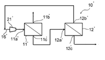
- a two-stage separation system 10'as shown in FIG. has been used conventionally.
- the system 10'in FIG. 3 is a gas separation system including two gas separation membrane units 11'and 12'.
- the mixed gas as a raw material is supplied to the first gas separation membrane unit 11', and the non-permeated gas from the first gas separation membrane unit 11'is supplied to the second gas separation membrane unit 12'.
- the non-permeated gas supplied from the second gas separation membrane unit 12' is recovered as a product gas.
- the permeated gas from the second gas separation membrane unit 12' merges with the raw material gas again and is supplied to the first gas separation membrane unit 11'.
- a two-stage gas separation system that separates the permeated gas of the first gas separation membrane unit in the second stage has also been proposed in the application of extracting the permeated gas as a product gas (Patent Document 1). ).
- an object of the present invention is to provide a gas separation system that can eliminate the drawbacks of the above-mentioned prior art.
- the present invention is a gas separation system including a first gas separation membrane unit and a second gas separation membrane unit, which is used for producing CH 4- enriched gas from a raw material gas containing CO 2 and CH 4 .
- Each gas separation membrane unit includes at least a gas inlet, a permeated gas outlet and a non-permeated gas outlet.
- the raw material gas supply line connected to the gas inlet of the first gas separation membrane unit,
- the compression means placed in the raw material gas supply line and A first connecting line that connects the permeated gas discharge port of the first gas separation membrane unit and the gas inlet of the second gas separation membrane unit, It has a second connecting line that connects the impermeable gas discharge port of the second gas separation membrane unit and the raw material gas supply line.
- the gas separation selectivity P'CO2 / P'CH4 of the first gas separation membrane unit and the second gas separation membrane unit is 30 or more.
- the recovery rate of CH 4 is 98% or more, the CO 2 content in the impermeable gas discharged from the impermeable gas discharge port of the first gas separation membrane unit is 5 mol% or less, and the second gas separation is performed.
- a gas separation system in which the amount of gas supplied to the membrane unit per hour is 60% or less of the amount of raw material gas supplied to the first gas separation membrane unit per hour. ..
- the present invention is a method for producing CH 4- enriched gas from a raw material gas containing CO 2 and CH 4 using a gas separation system.
- a gas separation system Equipped with a first gas separation membrane unit and a second gas separation membrane unit, Each gas separation membrane unit includes at least a gas inlet, a permeated gas outlet and a non-permeated gas outlet.
- the raw material gas supply line connected to the gas inlet of the first gas separation membrane unit, A compression means intervening in the raw material gas supply line, A first connecting line that connects the permeated gas discharge port of the first gas separation membrane unit and the gas inlet of the second gas separation membrane unit, It has a second connecting line that connects the impermeable gas discharge port of the second gas separation membrane unit and the raw material gas supply line.
- the recovery rate of CH 4 is 98% or more, the CO 2 content in the impermeable gas discharged from the impermeable gas discharge port of the first gas separation membrane unit is 5 mol% or less, and the first gas separation is performed.
- a method for producing CH 4- enriched gas in which the gas separation system is operated so that the amount of permeated gas per hour of the membrane unit is 60% or less of the amount of raw material gas per hour supplied to the first gas separation membrane unit. Is to provide.
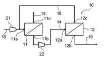
- FIG. 1 is a schematic view showing the configuration of a gas separation system for methane separation according to an embodiment of the present invention.
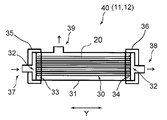
- FIG. 2 is a schematic view showing the structure of an example of a module constituting the gas separation membrane unit used in the gas separation system of the present invention.
- FIG. 3 is a schematic view showing the configuration of a conventional gas separation system for methane separation.
- the gas separation system 10 which is a preferred embodiment of the present invention and a preferred embodiment of the present invention for producing a CH 4- enriched gas using the gas separation system 10 will be described.
- the gas separation system 10 of the present embodiment includes two gas separation membrane units, a first gas separation membrane unit 11 and a second gas separation membrane unit 12.
- a module 40 having a gas separation membrane 30 made of a hollow fiber membrane or the like and having gas selective permeability is housed in a casing 31 is used. Can be done.
- the permeation rate of CO 2 is P'CO2 (cm 3 (STP) / (cm 2 ⁇ sec ⁇ cmHg)) and the permeation rate of CH 4 is P'CH4 (cm). is higher than the 3 (STP) / (cm 2 ⁇ sec ⁇ cmHg)).
- Each of the gas separation membrane units 11 and 12 of the present embodiment uses one gas separation membrane module 40 shown in FIG. 2, or a plurality of these modules 40 are arranged in parallel.
- the casing 31 in the module 40 has two facing surfaces open to form an opening 32.
- the opening 32 is for inserting the gas separation membrane 30 into the casing 31, not the opening of the gas separation membrane 30.
- the gas separation membrane 30 is housed in the casing 31 through the opening 32.
- the gas separation membrane 30 is composed of a bundle of hollow fiber membranes in which a large number of hollow fiber membranes are bundled so as to coincide with each other in the longitudinal direction, the gas separation membrane 30 is in the accommodation state, and each opening 32 of the casing 31 is formed. It is housed in the casing 31 so that each end of the hollow fiber membrane opens in the vicinity of.
- the gas separation membrane 30 In the state where the gas separation membrane 30 is housed in the casing 31, the gas separation membrane 30 is fixed to the inner wall of the casing 31 by the tube plates 33 and 34 at the positions of both ends in the Y direction, which is the extending direction of the hollow fiber membrane. Has been done.
- Each opening 32 of the casing 31 is closed by lids 35 and 36.
- the lid 35 is provided with a gas inlet 37.
- the lid 36 is provided with a non-permeated gas discharge port 38.
- the mixed gas to be separated is introduced into the module (that is, the unit) from the gas inlet 37 of the lid 35.
- the gas that has permeated through the gas separation membrane 30 is discharged to the outside of the module (that is, outside the unit) from the permeation gas discharge port 39 provided in the casing 31.
- the impermeable gas that has not permeated through the gas separation membrane 30 is discharged to the outside of the module (that is, outside the unit) from the impermeable gas discharge port 38 of the lid 36.
- the casing 31 may be provided with a purge gas supply port (not shown).
- first gas separation membrane unit 11 and the second gas separation membrane unit 12 are connected in series. Specifically, the first gas separation membrane unit 11 and the second gas separation membrane unit 12 are the permeation gas discharge port 11b of the first gas separation membrane unit 11 and the gas inlet 12a of the second gas separation membrane unit 12. Is connected by connecting with the first connecting line 14.
- a raw material gas supply line 16 for supplying a raw material gas from a mixed gas source (not shown) as a raw material to the first gas separation membrane unit 11 is connected to the gas inlet 11a of the first gas separation membrane unit 11.
- a second connecting line 18 for supplying the non-permeable gas of the second gas separation membrane unit 12 to the first gas separation membrane unit 11 is connected to the non-permeable gas discharge port 12c of the second gas separation membrane unit 12.
- the second connecting line 18 may be connected to either the discharge side or the suction side of the first compression means 21 in the raw material gas supply line 16, but from the viewpoint of suppressing the required compression power of the system, the second connection line 18 may be connected to the discharge side. It is preferable that they are connected.
- the first compression means 21 is interposed in the middle of the raw material gas supply line 16.
- the first compression means 21 is installed for the purpose of pressurizing the raw material gas and supplying it to the first gas separation membrane unit 11.
- the second compression means 22 is interposed and arranged in the middle of the first connection line 14.
- the second means 22 is installed for the purpose of pressurizing the permeated gas discharged from the permeated gas discharge port 11b of the first gas separation membrane unit 11 and supplying it to the second gas separation membrane unit 12.
- a compressor can be used as the first compression means 21 and the second compression means 22.
- the system 10 is connected to the non-permeable gas discharge port 11c of the first gas separation membrane unit 11, and has a first take-out line 15 for taking out the non-permeable gas from the discharge port 11c to the outside of the system, and a second gas separation membrane unit. It is connected to the permeated gas discharge port 12b of 12, and has a second take-out line 19 for taking out the permeated gas from the discharge port 12b to the outside of the system.
- the raw material gas to be separated is supplied from the mixed gas source (not shown) to the first gas separation membrane unit 11 through the raw material gas supply line 16.
- the raw material gas contains at least CO 2 and CH 4 to be separated.
- the permeated gas which is the gas that has permeated the gas separation membrane, and the gas are separated due to the difference in the permeation rate with respect to the gas separation membrane. It is separated into a non-permeated gas, which is a gas that has not permeated the membrane.
- any gas separation membrane of the first gas separation membrane unit 11 and the second gas separation membrane unit 12 has a larger CO2 'permeation rate P of CO 2 compared to CH4' permeation rate P of CH 4 ..
- the non-permeated gas discharged from the non-permeated gas discharge port 11c of the first gas separation membrane unit 11 is one in which CH 4 is concentrated as compared with the raw material gas.
- the non-permeated gas is discharged from the non-permeated gas discharge port 11c and is taken out of the system through the first take-out gas line 15.
- the permeated gas from the first gas separation membrane unit 11 is one in which CO 2 is concentrated as compared with the raw material gas.
- the permeated gas is discharged from the permeated gas discharge port 11b, supplied to the second gas separation membrane unit 12 through the first connecting line 14, and further discharged from the permeated gas discharge port 12b of the second gas separation membrane unit 12.
- the carbon-enriched gas is taken out of the system.
- the non-permeated gas of the second gas separation membrane unit 12 passes through the second connecting line 18 again from the non-permeated gas discharge port 12c, is introduced into the raw material gas supply line 16, and merges with the raw material gas to be the first gas. It is supplied to the separation membrane unit 11.
- the CO 2 content in the impermeable gas discharged from the impermeable gas discharge port 11c of the first gas separation membrane unit 11 is 5 mol% or less. Further, in order to increase the purity of CH 4 in the non-permeated gas, the CO 2 content in the non-permeated gas is particularly preferably 3 mol% or less.
- the CH 4 purity in the non-permeated gas is preferably 95 mol% or more, more preferably 97 mol% or more.
- the recovery rate of CH 4 is 98% or more, and it is particularly preferable that it is 98.5% or more.
- Recovery of CH 4 is discharged per unit time from the non-permeate gas outlet 11c of the first gas separation membrane unit 11 to the amount of CH 4 in the raw material gas per unit time is introduced into the first gas separation membrane unit 11 It is calculated as the amount of CH 4 in the non-permeated gas.
- the recovery rate is a ratio based on the volume in the standard state.
- CH 4 is a greenhouse gas. Recovery is preferably low from the viewpoint of membrane area and energy consumption, high recovery is desired in order to suppress the loss of CH 4 gas.
- the gas supplied to the first gas separation membrane unit 11 has a flow rate (F2) (gas amount per hour, unit Nm 3 / h) of the gas supplied to the second gas separation membrane unit 12.
- the ratio to the flow rate (F1) (hereinafter, also referred to as “supply flow rate ratio (F2 / F1)”) is set to 60% or less.
- the supply flow rate of the second gas separation membrane unit 12 is set to a certain level or less, the flow rate of the entire system that depends on this flow rate is suppressed, and the entire system that depends on the flow rate is compressed. Power can be suppressed.
- the compression power of the second compression means 22 can be significantly reduced.
- the supply flow rate ratio (F2 / F1) is more preferably 50% or less. The lower the supply flow rate ratio (F2 / F1), the better, but usually it is 10% or more or 20% or more.
- the gas separation selectivity P'CO2 / P'CH4 is a specific value for each of the first gas separation membrane unit 11 and the second gas separation membrane unit 12.
- Gas separation selectivity (P 'CO2 / P' CH4 ) 1 and the gas separation selectivity of the second gas separation membrane unit 12 (P 'CO2 / P' CH4) 2 of specifically the first gas separation membrane unit 11 All of them are 30 or more, which means that the compression power of the second compression means 22 can be reduced, and the film area can be reduced and the compression power can be suppressed at the same time while reducing the amount of CO 2 gas in the product gas.
- Gas separation selectivity (P 'CO2 / P' CH4 ) 1 and the gas separation selectivity of the second gas separation membrane unit 12 (P 'CO2 / P' CH4) 2 of the first gas separation membrane unit 11 is 35 or more Is more preferable.
- Gas separation selectivity (P 'CO2 / P' CH4 ) 1 and the gas separation selectivity of the second gas separation membrane unit 12 (P 'CO2 / P' CH4) 2 of the first gas separation membrane unit 11 is generally 120 or less Is preferable from the viewpoint of ease of manufacturing the gas separation membrane unit.
- the ratio of the membrane area S1 of the first gas separation membrane unit 11 to the membrane area S2 of the second gas separation membrane unit is preferably S1 / S2 of 1 or more and 14 or less because F2 / F1 can easily be in the above range. More preferably, it is 2 or more and 12 or less.
- constitutes two units gas separation selectivity of the first gas separation membrane units 11 (P 'CO2 / P' CH4) 1 and the gas separation selectivity of the second gas separation membrane unit 12 (P 'CO2 / P'CH4 ) 2 may be the same or different.
- the 'transmission rate P of CO 2 CO2 1 and the second gas separation membrane unit 12' CH4 2 first gas separation membrane unit 11 permeation rate P of CO 2 may be different may be the same.
- permeation rate P of the CO 2 of the first gas separation membrane unit 'CO2 1 is permeation rate P of the CO 2 gas separation membrane used in the second gas separation membrane unit' higher than the CO2 2, the system It is preferable in that the number of membrane modules can be reduced without significantly impairing the overall efficiency.
- the ratio of the permeation rates of both P'CO2 2 / P'CO2 1 is preferably 0.7 or less, more preferably 0.5 or less.
- Aforementioned gas separation selectivity P 'CO2 / P' CH4 ( P 'CO2 / P' CH4 1 and P 'CO2 / P' CH4 2 ) and permeation rate P of CO 2 'CO2 (P' CO2 1 and P 'CO2 2), respectively, it may be a permeation rate P 'CO2 gas separation selectivity P' CO2 / P 'CH4 and CO 2 in the temperature conditions in the gas separation membrane unit during operation.
- the gas permeation rate may be lower than when the operating temperature is set relatively high.
- the operating temperature of each unit may be different, and the permeation speed between the two units may be the above-mentioned relationship.
- the operating temperature of the second gas separation membrane unit 12 is made higher than that of the first gas separation membrane unit 11, and the permeation rate of CO 2 of the first gas separation membrane unit 11 is higher than that of P'CO2 1.
- the P'CO2 2 of the unit 12 may be increased.
- the operating temperature of the first gas separation membrane unit 11 is made higher than that of the second gas separation membrane unit 12, and the permeation rate of CO 2 of the second gas separation membrane unit 12 is higher than that of P'CO2 2.
- the P'CO2 1 of the unit 11 may be increased.
- the difference in operating temperature is preferably 5 ° C. or higher, more preferably 20 ° C. or higher, and particularly preferably 40 ° C. or higher.
- the operating temperature of the first gas separation membrane unit 11 and the second gas separation membrane unit is not particularly limited, and is, for example, room temperature or higher and 80 ° C. or lower.
- Gas separation selectivity of the first gas separation membrane unit 11 ( P'CO2 / P'CH4 ) 1 and gas separation selectivity of the second gas separation membrane unit 12 ( P'CO2 / P'CH4 ) 2 ratio (P' CO2 / P 'CH4) 1 / (P' CO2 / P 'CH4) 2 is preferably to increase the CH 4 recovery rate while suppressing module number, for example 0.2 to 1.1, It is more preferably 0.2 or more and 1 or less.
- the gas separation system and gas separation method of the present invention include, for example, 40 volumes of CH 4 in a total of 100% by volume of CH 4 and CO 2. It can be used for separating a raw material gas or the like having a CO 2 content of 20% by volume or more and 60% by volume or less.
- carbon dioxide (CO 2) and methane (CH 4) is carbon dioxide (CO 2) volume ratio of the well be larger than methane (CH 4), the volume ratio of carbon dioxide (CO 2) It may be smaller than methane (CH 4 ).
- the total ratio of CH 4 and CO 2 in the raw material gas is preferably 95% by volume or more, and more preferably 98% by volume or more.
- Biogas refers to a gas generated by methane fermentation of organic waste by the action of anaerobic microorganisms.
- biogas include digestion gas generated by anaerobic fermentation of sewage sludge and landfill gas generated from a landfill site for waste.
- organic waste include the above-mentioned sewage sludge and landfill waste, manure from dairy cows and pigs, and food residues.
- the raw material gas is natural gas because the gas separation system of the present invention can be preferably used.
- the gas separation membranes in the gas separation membrane units 11 and 12 can be appropriately selected according to the type of mixed gas to be supplied and the target product gas.
- the gas separation membrane the same ones used so far in the technical field can be used without particular limitation. Examples thereof include rubber-like polymer materials such as silicone resin and polybutadiene resin, glassy polymer materials such as polyimide, polyetherimide, polyamide, polyamideimide, polysulfone, polycarbonate and cellulose, and ceramic materials such as zeolite.
- the gas separation membrane may be a homogeneous membrane, an asymmetric membrane composed of a homogeneous layer and a porous layer, a microporous membrane, or the like.
- the form of storing the gas separation membrane in the casing may be any of a plate-and-frame type, a spiral type, a hollow fiber type and the like.
- a particularly preferably used gas separation membrane is a hollow fiber gas separation membrane of aromatic polyimide.
- the hollow fiber gas separation membrane preferably has an asymmetric structure in which the thickness of the homogeneous layer is 10 nm or more and 200 nm or less, and the thickness of the porous layer is 20 ⁇ m or more and 200 ⁇ m or less.
- the inner diameter of the hollow fiber membrane is preferably about 30 ⁇ m or more and 500 ⁇ m or less.
- the number of gas separation membrane modules provided in one gas separation membrane unit may be one or a plurality. When two or more gas separation membrane modules are provided in one gas separation membrane unit, it is preferable that they are connected in parallel in the unit. When each gas separation membrane unit includes a plurality of gas separation membrane modules, the membrane area in the unit can be easily adjusted by changing the number of the gas separation membrane modules.
- the pressure of the gas sent to the first gas separation membrane unit 11 and the second gas separation membrane unit 12 made of the hollow fiber membrane is 0.2 MPaG to 2.0 MPaG. It is preferable that the pressure of the gas sent to the second gas separation membrane unit 12 is slightly higher (about 0 to 0.3 MPaG) than the pressure of the gas sent to the first gas separation membrane unit 11.
- the present invention has been described above based on the preferred embodiment, the present invention is not limited to the above embodiment.
- the second compression means 22 is interposed in the first connecting line 14.
- the compression power can be further reduced. preferable.
- a gas separation membrane unit having a hollow fiber membrane is used as an example of each gas separation membrane unit, but a gas separation membrane unit of another form may be used instead.
- Examples 1-1 to 1-5 The mixed gas containing carbon dioxide and methane was separated using the gas separation system 10 shown in FIG. A compressor was used as the first compression means 21 in the system 10. Gas mixture composition used was the CO 2 40 vol%, CH 4 60% by volume. As modules constituting the first and second gas separation membrane unit 11, 12, P 'CO2 is 9.62 ⁇ 10 -5 cm 3 (STP ) / (cm 2 ⁇ sec ⁇ cmHg), P' CH4 is 0.
- a gas separation selectivity P 'CO2 / P' CH4 is 61.91
- a gas separation membrane composed of polyimide hollow fiber membranes A plurality of gas separation membrane modules housed in the case were connected in parallel and used.
- the operating temperature of the first and second gas separation membrane units 11 and 12 was 35 ° C.
- the number of gas separation membrane modules constituting the first gas separation membrane unit 11 was set to 70, and the number of gas separation membrane modules constituting the second gas separation membrane unit 12 was set to the value shown in Table 1.
- the mixed gas is supplied to the first gas separation membrane unit 11 at a flow rate of 500 Nm 3 / h and a pressure of 1 MPaG, and the permeated gas of the first gas separation membrane unit 11 is supplied to the second gas separation membrane unit 11 at a pressure of 1.1 MPaG. It was supplied to the unit 12 and the non-permeated gas of the second gas separation membrane unit 12 was returned to the first gas separation membrane unit 11.
- the permeated gas pressure at the permeated gas discharge port of the first gas separation membrane unit 11 and the permeated gas pressure at the permeated gas discharge port of the second gas separation membrane unit 12 were 0.03 MPaG. Under these conditions, the supply flow rate to each unit is shown in Table 1. Further, the composition of the non-permeated gas of the first gas separation membrane unit 11, the recovery rate of CH 4 (Rcv.,%), The flow rate of the permeated gas and the non-permeated gas of each unit, the supply flow rate ratio (F2 / F1), and the first 2 Table 1 shows the compression power of the compression means 22 and the total compression power (sum of the compression powers of the compression means 21 and 22).
- Examples 2-1 to 2-5 Examples except that the number of gas separation membrane modules of the first gas separation membrane unit 11 is set to 80 and the number of gas separation membrane modules constituting the second gas separation membrane unit 12 is set to the value shown in Table 1. It was the same as 1-1.
- Table 1 shows the supply flow rate to each unit. Further, the composition of the non-permeated gas of the first gas separation membrane unit 11, the recovery rate of CH 4 (Rcv.,%), The flow rate of the permeated gas and the non-permeated gas of each unit, the supply flow rate ratio (F2 / F1), the first. 2 Table 1 shows the compression power and the total compression power of the compression means 22.
- Examples 3-1 to 3-6 As modules constituting the first gas separation membrane unit 11 and the second gas separation membrane unit 12, P'CO2 is 8.49 ⁇ 10-5 cm 3 (STP) / (cm 2 ⁇ sec ⁇ cmHg), P'CH4. There 0.16 ⁇ 10 -5 cm 3 (STP ) / (cm 2 ⁇ sec ⁇ cmHg), a gas separation selectivity P 'CO2 / P' CH4 is 54.63, the gas composed of the polyimide hollow fiber membranes A plurality of gas separation membrane modules for accommodating the separation membrane in the case were connected in parallel and used. Except for these points, the same as in Example 2-1.
- the number of gas separation membrane modules of the first gas separation membrane unit 11 and the second gas separation membrane unit 12 was set to the number shown in Table 2. Except for these points, the same as in Example 1-1.
- Table 2 shows the supply flow rate to each unit. Further, the composition of the non-permeated gas of the first gas separation membrane unit 11, the recovery rate of CH 4 (Rcv.,%), The flow rate of the permeated gas and the non-permeated gas of each unit, the supply flow rate ratio (F2 / F1), the first. 2 Table 2 shows the compression power and the total compression power of the compression means 22.
- the number of gas separation membrane modules constituting the first gas separation membrane unit 11' was set to the values shown in Table 3.
- the number of gas separation membrane modules constituting the second gas separation membrane unit 12' was set to 70.
- the mixed gas is supplied to the first gas separation membrane unit 11'with a flow rate of 500 Nm 3 / h and a pressure of 1 MPaG, and the non-permeated gas of the first gas separation membrane unit 11'is sent to the second gas separation membrane unit 12'. It was supplied and the permeated gas of the second gas separation membrane unit 12'was returned to the first gas separation membrane unit 11'.
- the permeation gas pressure at the permeation gas discharge port of the first gas separation membrane unit 11'and the permeation gas pressure at the permeation gas discharge port of the second gas separation membrane unit 12 were 0.03 MPaG.
- Table 3 shows the supply flow rate to each unit. Further, the composition of the non-permeated gas of the second gas separation membrane unit 12, the recovery rate of CH 4 (Rcv.,%), The permeated gas of each unit, the flow rate of the non-permeated gas, and the compression power of the first compression means 21'. It is shown in Table 3.
- the CO 2 concentration in the non-permeated gas of the first gas separation membrane unit 11 is 5 mol% or less
- the recovery rate of CH 4 is 98% or more
- the second gas separation membrane unit 11 The amount of permeated gas per hour (F2) supplied to the unit is set to be 60% or less of the amount of raw material gas per hour (F1) supplied to the first gas separation membrane unit. It can be seen that in the gas separation system of each embodiment in Table 1, the increase in compression power is suppressed even if the total number of modules of the first and second gas separation membrane unit modules is reduced.
- Comparative Examples 7-2 to 7-5 and Examples 3-1 to 3-3 which adopted the same separation selectivity and membrane area conditions of the gas separation membrane as in Examples 2-1 to 2-5.
- Comparative Examples 8-1 and 8-2 in which the separation selectivity and the membrane area condition of the gas separation membrane similar to 6 are adopted, when the membrane area of the first gas separation membrane unit 11 is reduced, the compression power becomes large. It can be seen that the product purity is reduced.
- Examples 4-1 to 4-17 The volume ratio of CO 2 / CH 4 was changed as shown in Table 4 below, and the number of modules of each unit was changed as shown in Table 4 in the same manner as in Example 1-1.
- Table 4 shows the supply flow rate to each unit. Further, the composition of the non-permeated gas of the first gas separation membrane unit 11, the recovery rate of CH 4 (Rcv.,%), The flow rate of the permeated gas and the non-permeated gas of each unit, the supply flow rate ratio (F2 / F1), the first. 2 Table 4 shows the compression power and the total compression power of the compression means 22.
- the present invention achieves a high recovery rate and high purity of CH 4 , while increasing the membrane area as compared with the conventional gas separation system. It can be seen that the increase in the required compression power is suppressed when the amount is reduced.
- Examples 5-1 to 5-6 The same as in Example 1-1 except that the number of gas separation membrane modules of the first gas separation membrane unit 11 and the second gas separation membrane unit 12 was set to the number shown in Table 5.
- the supply flow rate to each unit is shown in Table 5.
- the compression power of the compression means 22 and the total compression power are shown in Table 5.
- Examples 6-1 to 6-7, 7-1 to 7-7 The same as in Example 3-1 except that the number of gas separation membrane modules of the first gas separation membrane unit 11 and the second gas separation membrane unit 12 was set to the number shown in Table 5.
- the supply flow rate to each unit is shown in Table 5.
- the compression power of the compression means 22 and the total compression power are shown in Table 5.
- Example 8-1 to 8-11 As modules constituting the first and second gas separation membrane unit 11, 12, P 'CO2 is 6.79 ⁇ 10 -5 cm 3 (STP ) / (cm 2 ⁇ sec ⁇ cmHg), P' CH4 is 0. 16 ⁇ 10 -5 cm 3 (STP ) / (cm 2 ⁇ sec ⁇ cmHg), a gas separation selectivity P 'CO2 / P' CH4 is 43.70, a gas separation membrane composed of polyimide hollow fiber membranes A plurality of gas separation membrane modules housed in the case were connected in parallel and used. The number of gas separation membrane modules of the first gas separation membrane unit 11 and the second gas separation membrane unit 12 was set to the number shown in Table 5.
- Example 1-1 The supply flow rate to each unit is shown in Table 5. Further, the composition of the non-permeated gas of the first gas separation membrane unit 11, the recovery rate of CH 4 (Rcv.,%), The flow rate of the permeated gas and the non-permeated gas of each unit, the supply flow rate ratio (F2 / F1), the first. 2 The compression power of the compression means 22 and the total compression power are shown in Table 5.
- a gas separation system for methane separation and methane enrichment which can reduce the membrane area while suppressing the required compression power as compared with the conventional gas separation system while achieving high recovery rate and high purity of CH 4.
- a method for producing gas is provided.
Abstract
ガス分離システム(10)は、第1ガス分離膜ユニット(11)及び第2ガス分離膜ユニット(12)と、該ユニット(11)のガス入口(11a)に連結する原料ガス供給ライン(16)と、該ライン(16)に介在配置した第1圧縮手段(21)とユニット(11)の透過ガス排出口(11b)とユニット(12)のガス入口(12a)とを連結する第1連結ライン(14)と、ユニット(12)の非透過ガス排出口(12c)とライン(16)とを連結する第2連結ライン(18)とを有し、ユニット(11)及びユニット(12)のガス分離選択性(P'CO2/P'CH4)が30以上、CH4回収率が98%以上、ユニット(11)の非透過ガス中のCO2含量が5モル%以下、ユニット(12)に供給されるガス流量が、ユニット(11)に供給される原料ガス流量の60%以下である。
Description
本発明は、二酸化炭素(CO2)及びメタン(CH4)を含む原料ガスから、複数のガス分離膜ユニットを用いてCH4富化ガスを製造するガス分離システムに関する。
CO2及びCH4を含む原料ガスを各ガスに分離する方法として、膜に対するこれらのガスの透過速度の差を利用した膜分離法が知られている。この方法では通常、非透過ガスを回収することにより、目的ガスである高純度のCH4富化ガスを得ることができる。原料ガスに含まれるCO2及びCH4の膜に対する単位膜面積・単位時間・単位分圧差あたりの透過体積である透過速度は、P'CO2 及びP'CH4(単位は、×10-5cm3(STP)/(cm2・sec・cmHg))で表すことができる。また、CO2及びCH4の膜のガス分離選択性はこれら透過速度の比、P'CO2 / P'CH4(高透過性ガスの透過速度/低透過性ガスの透過速度)で表すことができる。
一般に、ガス分離膜は、ガス選択透過性を有するガス分離膜を、少なくともガス入口、透過ガス排出口、非透過ガス排出口が備えられている容器内に収容してなるガス分離膜モジュールとして使用されている。ガス分離膜は、そのガス供給側とガス透過側の空間が隔離されるように、容器内に装着されている。ガス分離システムにおいては、所要の膜面積とするために、一般に複数のガス分離膜モジュールを並列に組み合わせたガス分離膜ユニットとして使用される。ガス分離膜ユニットを構成する複数のガス分離膜モジュールは、ガス入口、非透過ガス排出口、透過ガス排出口を共用するため、ガス分離膜ユニットは、実質的に膜面積が大きいガス分離膜モジュールとして作用する。
目的とするCH4を高純度かつ高回収率で回収するために、ガス分離膜ユニットを多段階に備えたガス分離システムを用いる方法として、例えば図3に示すような2段の分離システム10’が従来用いられている。図3のシステム10’は、2つのガス分離膜ユニット11’、12’を備えたガス分離システムである。このガス分離システム10’では、原料となる混合ガスが第1ガス分離膜ユニット11’に供給され、該第1ガス分離膜ユニット11’からの非透過ガスが第2ガス分離膜ユニット12’に供給され、第2ガス分離膜ユニット12’からの非透過ガスが製品ガスとして回収される。第2ガス分離膜ユニット12’からの透過ガスは再度原料ガスと合流して第1ガス分離膜ユニット11’に供給される。
一方、CH4分離とは異なり、透過ガスを製品ガスとして取り出す用途において、第1ガス分離膜ユニットの透過ガスを2段目において分離する2段のガス分離システムも提案されている(特許文献1)。
一方、CH4分離とは異なり、透過ガスを製品ガスとして取り出す用途において、第1ガス分離膜ユニットの透過ガスを2段目において分離する2段のガス分離システムも提案されている(特許文献1)。
非透過ガスを2段目に送る図3のガス分離システム10’では、CH4回収率を高めながら製品ガスであるCH4富化ガス中のCO2濃度を低減させようとすると、原料ガス流量に対する第2ガス分離膜ユニット12’からの戻りガス流量(つまり第2ガス分離膜ユニット12’からの透過ガス流量)の割合が増加してしまい、結果としてシステム10’全体のガス流量が増加するために、システム10’全体として圧縮動力を高める必要があった。これに対し、原料ガス流量に対する第2ガス分離膜ユニット12’からの透過ガス流量の割合を低減させようとすると、第1ガス分離膜ユニット11’及び第2ガス分離膜ユニット12’の膜面積を増大させざるを得なかった。このために、図3に示す従来のCH4分離用ガス分離システム10’では、膜面積を低減させようとする場合、圧縮動力を増加させざるを得ず、圧縮動力の抑制と膜面積の低減とを両立させることが困難であった。
したがって本発明の課題は、前述した従来技術が有する欠点を解消し得るガス分離システムを提供することにある。
本発明は、第1ガス分離膜ユニット及び第2ガス分離膜ユニットを備え、CO2及びCH4を含む原料ガスからCH4富化ガスを製造するために用いられるガス分離システムであって、
各ガス分離膜ユニットは、ガス入口、透過ガス排出口及び非透過ガス排出口を少なくとも備え、
第1ガス分離膜ユニットのガス入口に連結する原料ガス供給ラインと、
原料ガス供給ラインに介在配置した圧縮手段と、
第1ガス分離膜ユニットの透過ガス排出口と第2ガス分離膜ユニットのガス入口とを連結する第1連結ラインと、
第2ガス分離膜ユニットの非透過ガス排出口と原料ガス供給ラインとを連結する第2連結ラインと、を有し、
第1ガス分離膜ユニット及び第2ガス分離膜ユニットのガス分離選択性P'CO2 / P'CH4が30以上であって、
CH4の回収率が98%以上であり、第1ガス分離膜ユニットの非透過ガス排出口から排出された非透過ガス中のCO2含量が5モル%以下であり、且つ、第2ガス分離膜ユニットに供給される時間当たりガス量が、第1ガス分離膜ユニットに供給される時間当たり原料ガス量に対し、60%以下となるようになされている、ガス分離システムを提供するものである。
また本発明は、ガス分離システムを用いてCO2及びCH4を含む原料ガスからCH4富化ガスを製造する方法であって、
ガス分離システムとして、
第1ガス分離膜ユニット及び第2ガス分離膜ユニットを備え、
各ガス分離膜ユニットは、ガス入口、透過ガス排出口及び非透過ガス排出口を少なくとも備え、
第1ガス分離膜ユニットのガス入口に連結する原料ガス供給ラインと、
原料ガスの供給ラインに介在配置した圧縮手段と、
第1ガス分離膜ユニットの透過ガス排出口と第2ガス分離膜ユニットのガス入口とを連結する第1連結ラインと、
第2ガス分離膜ユニットの非透過ガス排出口と原料ガス供給ラインとを連結する第2連結ラインと、を有し、
第1ガス分離膜ユニット及び第2ガス分離膜ユニットのガス分離選択性P'CO2 / P'CH4が30以上であるガス分離システムを用い、
CH4の回収率が98%以上であり、第1ガス分離膜ユニットの非透過ガス排出口から排出される非透過ガス中のCO2含量が5モル%以下であり、且つ、第1ガス分離膜ユニットの時間当たり透過ガス量が、第1ガス分離膜ユニットに供給される時間当たり原料ガス量に対し、60%以下となるようにガス分離システムを運転する、CH4富化ガスの製造方法を提供するものである。
以下本発明を、その好ましい実施形態に基づき図面を参照しながら説明する。まず、図1及び図2に基づき、本発明の好ましい実施形態であるガス分離システム10及びこれを用いてCH4富化ガスを製造する本発明の好ましい実施態様について説明する。図1に示すように、本実施形態のガス分離システム10は、2つのガス分離膜ユニットである第1ガス分離膜ユニット11及び第2ガス分離膜ユニット12を備えている。各ガス分離膜ユニット11,12としては、例えば、図2に示すとおり、中空糸膜等からなり、ガス選択透過性を有するガス分離膜30をケーシング31内に収容してなるモジュール40を用いることができる。ガス分離膜ユニット11,12におけるガス分離膜はいずれも、CO2の透過速度P'CO2(cm3(STP)/(cm2・sec・cmHg))がCH4の透過速度P'CH4(cm3(STP)/(cm2・sec・cmHg))よりも高いものである。
本実施形態の各ガス分離膜ユニット11及び12は、図2に示すガス分離膜モジュール40を1本用いたものであるか、或いは、このモジュール40を複数本並列してなるものである。モジュール40におけるケーシング31は、対向する二面が開口して開口部32を形成している。この開口部32は、ガス分離膜30をケーシング31内に挿入するためのものであり、ガス分離膜30の開口部ではない点に留意すべきである。ガス分離膜30は、この開口部32を通じてケーシング31内に収容される。ガス分離膜30が多数本の中空糸膜が長手方向を一致するように束ねてなる中空糸膜束から構成される場合、該ガス分離膜30はその収容状態において、ケーシング31の各開口部32の付近において中空糸膜の各端部が開口するように、ケーシング31内に収容される。
ガス分離膜30がケーシング31内に収容された状態においては、中空糸膜の延びる方向であるY方向の両端部の位置において、ガス分離膜30が管板33,34によってケーシング31の内壁に固定されている。ケーシング31の各開口部32は、蓋体35,36によって閉塞されている。蓋体35にはガス入口37が設けられている。一方、蓋体36には非透過ガス排出口38が設けられている。分離対象となる混合ガスは、蓋体35のガス入口37からモジュール内(すなわちユニット内)に導入される。導入されたガスのうち、ガス分離膜30を透過したガスは、ケーシング31に設けられた透過ガス排出口39からモジュール外(すなわちユニット外)に排出される。一方、ガス分離膜30を透過しなかった非透過ガスは、蓋体36の非透過ガス排出口38からモジュール外(すなわちユニット外)に排出される。また、場合によっては、ケーシング31にパージガスの供給口(図示せず)を設けてもよい。以上、図2の分離膜モジュールを例に挙げて説明したが、当然ながら、本発明は他の構成の分離膜モジュールにも応用可能であり、例えば、シェルフィード型のモジュールやスパイラル型モジュールにも応用できる。
図1に戻ると、同図に示す通り、第1ガス分離膜ユニット11と、第2ガス分離膜ユニット12とが直列に接続されている。具体的には、第1ガス分離膜ユニット11と、第2ガス分離膜ユニット12とは、第1ガス分離膜ユニット11の透過ガス排出口11bと、第2ガス分離膜ユニット12のガス入口12aとを第1連結ライン14によって連結することで接続されている。
また第1ガス分離膜ユニット11のガス入口11aには、原料である混合ガス源(図示せず)からの原料ガスを第1ガス分離膜ユニット11へ供給するための原料ガス供給ライン16が連結されている。一方、第2ガス分離膜ユニット12の非透過ガス排出口12cには、第2ガス分離膜ユニット12の非透過ガスを第1ガス分離膜ユニット11へ供給するための第2連結ライン18が連結されている。第2連結ライン18は、原料ガス供給ライン16における第1圧縮手段21の吐出し側及び吸込み側のいずれに連結していてもよいが、システムの所要圧縮動力を抑制させる観点から、吐出側に連結していることが好ましい。
第1圧縮手段21が原料ガス供給ライン16の途中に介在配置されている。第1圧縮手段21は、原料ガスを加圧して、第1ガス分離膜ユニット11に供給する目的で設置されている。但し、ガス分離システムが原料ガスとして油田などから送出される等して圧力を有するガスを分離する場合は、第1ガス分離膜ユニット11に供給される原料ガスを加圧するための第1圧縮手段21を原料ガス供給ライン16に設けなくとも、原料ガスの分離を行うことが可能である。
また第2圧縮手段22が第1連結ライン14の途中に介在配置されている。第2手段22は、第1ガス分離膜ユニット11の透過ガス排出口11bから排出された透過ガスを加圧して、第2ガス分離膜ユニット12に供給する目的で設置されている。第1圧縮手段21及び第2圧縮手段22としては圧縮機を用いることができる。
また第2圧縮手段22が第1連結ライン14の途中に介在配置されている。第2手段22は、第1ガス分離膜ユニット11の透過ガス排出口11bから排出された透過ガスを加圧して、第2ガス分離膜ユニット12に供給する目的で設置されている。第1圧縮手段21及び第2圧縮手段22としては圧縮機を用いることができる。
システム10は、第1ガス分離膜ユニット11の非透過ガス排出口11cに連結し、該排出口11cから非透過ガスをシステム外に取り出すための第1取り出しライン15と、第2ガス分離膜ユニット12の透過ガス排出口12bに連結し、該排出口12bから透過ガスをシステム外に取り出すための第2取り出しライン19と、をそれぞれ有している。
以上の構成を有する本実施形態のガス分離システム10の動作について説明する。分離対象となる原料ガスは、混合ガス源(図示せず)から原料ガス供給ライン16を通じて第1ガス分離膜ユニット11に供給される。
原料ガスは、分離対象となるCO2及びCH4を少なくとも含むものである。加圧された状態の原料ガスが第1ガス分離膜ユニット11に供給されると、ガス分離膜に対する透過速度の相違に起因して、ガス分離膜を透過したガスである透過ガスと、ガス分離膜を透過しなかったガスである非透過ガスとに分離される。上述したように、第1ガス分離膜ユニット11及び第2ガス分離膜ユニット12におけるガス分離膜はいずれも、CH4の透過速度P'CH4に比してCO2の透過速度P'CO2が大きい。第1ガス分離膜ユニット11の非透過ガス排出口11cから排出される非透過ガスは、原料ガスに比べてCH4が濃縮されたものである。該非透過ガスは、非透過ガス排出口11cから排出され、第1取り出しガスライン15を通じてシステム外へ取り出される。一方、第1ガス分離膜ユニット11からの透過ガスは、原料ガスに比べてCO2が濃縮されたものである。該透過ガスは、透過ガス排出口11bから排出され、第1連結ライン14を通じて第2ガス分離膜ユニット12に供給され、第2ガス分離膜ユニット12の透過ガス排出口12bから排出された更に二酸化炭素が濃縮されたガスがシステム外に取り出される。また、第2ガス分離膜ユニット12の非透過ガスは、再度非透過ガス排出口12cから第2連結ライン18を通り、原料ガス供給ライン16に導入されて、原料ガスと合流して第1ガス分離膜ユニット11に供給される。
本実施形態のガス分離システム10は、第1ガス分離膜ユニット11の非透過ガス排出口11cから排出される非透過ガス中のCO2含量が5モル%以下である。更に非透過ガス中のCH4純度を高めるため、非透過ガス中のCO2含量は3モル%以下であることが特に好ましい。非透過ガス中のCH4純度は95モル%以上であることが好ましく、97モル%以上であることがより好ましい。
更に、本実施形態においては、CH4の回収率が98%以上であり、98.5%以上であることが特に好ましい。CH4の回収率は第1ガス分離膜ユニット11に導入される単位時間当たりの原料ガス中のCH4の量に対する第1ガス分離膜ユニット11の非透過ガス排出口11cから単位時間当たり排出される非透過ガス中のCH4の量として算出される。回収率は標準状態における体積を基準とした割合である。CH4の回収率を高めることは、温室効果ガスであるCH4のシステム外への排出量を低減させることによる温暖化防止の点からも好ましい。回収率は、膜面積や消費エネルギーの観点からは低い方が好ましいが、CH4ガスのロスを抑えるために高回収率が要望される。
本実施形態において、第2ガス分離膜ユニット12に供給されるガスの流量(F2)(時間当たりのガス量、単位Nm3/h)の、第1ガス分離膜ユニット11に供給されるガスの流量(F1)に対する比率(以下「供給流量比(F2/F1)」ともいう)が、60%以下となるようになされている。これにより、本実施形態のシステム10では、第2ガス分離膜ユニット12の供給流量を一定以下のものとして、この流量に依存するシステム全体の流量を抑制し、当該流量に依存するシステム全体の圧縮動力を抑制できる。特に本実施形態のように第1連結ライン14の途中に介在配置されている第2圧縮手段22を用いている場合にはこの第2圧縮手段22の圧縮動力を大きく削減できる。システムの所要圧縮動力をより一層抑制する観点から、より好ましくは、供給流量比(F2/F1)は50%以下である。供給流量比(F2/F1)は低ければ低いほどよいが、通常は、10%以上又は20%以上である。
本実施形態では、第1ガス分離膜ユニット11及び第2ガス分離膜ユニット12それぞれについて、ガス分離選択性P'CO2 / P'CH4が特定値であることを特徴の一つとしている。具体的には第1ガス分離膜ユニット11のガス分離選択性(P'CO2 / P'CH4)1及び第2ガス分離膜ユニット12のガス分離選択性(P'CO2 / P'CH4)2はいずれも30以上であり、これにより第2圧縮手段22の圧縮動力を削減でき、製品ガス中のCO2ガス量を低減しつつ膜面積の低減と圧縮動力の抑制とを両立させることができるという利点がある。第1ガス分離膜ユニット11のガス分離選択性(P'CO2 / P'CH4)1及び第2ガス分離膜ユニット12のガス分離選択性(P'CO2 / P'CH4)2は35以上であることがより好ましい。第1ガス分離膜ユニット11のガス分離選択性(P'CO2 / P'CH4)1及び第2ガス分離膜ユニット12のガス分離選択性(P'CO2 / P'CH4)2は、通常120以下であることがガス分離膜ユニットの製造容易性の点で好ましい。
第1ガス分離膜ユニット11の膜面積S1と第2ガス分離膜ユニットとの膜面積S2の比率はS1/S2が1以上14以下であることがF2/F1を上記の範囲としやすいために好ましく、2以上12以下であることがより好ましい。
本実施形態において、2つのユニットを構成する第1ガス分離膜ユニット11のガス分離選択性(P'CO2 / P'CH4)1及び第2ガス分離膜ユニット12のガス分離選択性(P'CO2 / P'CH4)2は同一であってもよく異なっていてもよい。また第1ガス分離膜ユニット11のCO2の透過速度P'CO2
1及び第2ガス分離膜ユニット12のCO2の透過速度P'CH4
2は、同一であってもよく異なってもよい。
逆に、第1ガス分離膜ユニットのCO2の透過速度P'CO2
1が、第2ガス分離膜ユニットで用いるガス分離膜のCO2の透過速度P'CO2
2に比べて高いことは、システム全体の効率を大きく損なわず膜モジュール本数を低減できる点で好ましい。
第1ガス分離膜ユニットのCO2の透過速度P'CO2
1が、第2ガス分離膜ユニットで用いるガス分離膜のCO2の透過速度P'CO2
2に比べて高い場合、上記の観点から、両者の透過速度の比P'CO2
2 / P'CO2
1は0.7以下が好ましく、0.5以下がより好ましい。
上述したガス分離選択性P'CO2/ P'CH4(P'CO2 / P'CH4
1及びP'CO2/ P'CH4
2)並びにCO2の透過速度P'CO2(P'CO2
1及びP'CO2
2)は、それぞれ、運転時の各ガス分離膜ユニットにおける温度条件におけるガス分離選択性P'CO2 / P'CH4及びCO2の透過速度P'CO2であればよい。
運転時においてユニット間でガス透過速度及び/又はガス分離選択性を異ならせる方法としては、ユニット間で使用するガス分離膜の種類を異ならせる方法が挙げられる。ユニット間でガス分離膜の種類を異ならせるには、ユニット間で(1)異なる化学組成を有する分離膜を用いる(2)同一の化学組成を有する分離膜であるが、製膜の条件、熱処理の温度といった製造条件が異なる分離膜を用いる(3)同一の化学組成および製造条件の分離膜であるが、コーティングその他の表面処理の条件が異なる分離膜を用いる等を行えばよい。
なお、同一のガス分離膜を用いた場合であっても、その運転温度を相対的に低く設定した場合には運転温度を相対的に高く設定した場合に比べ、ガス透過速度が低くなることが、一般的に知られている。
このことに基づき、各ユニットの運転温度を異ならせて、2つのユニット間の透過速度を上記の関係としてもよい。例えば、第1ガス分離膜ユニット11よりも第2ガス分離膜ユニット12の運転温度を高くして、第1ガス分離膜ユニット11のCO2の透過速度P'CO2 1よりも第2ガス分離膜ユニット12のP'CO2 2を高めてもよい。また、第2ガス分離膜ユニット12よりも第1ガス分離膜ユニット11の運転温度を高くして、第2ガス分離膜ユニット12のCO2の透過速度P'CO2 2よりも第1ガス分離膜ユニット11のP'CO2 1を高めてもよい。2つのユニットの運転温度を異ならせる場合、運転温度の差は5℃以上であることが好ましく、20℃以上であることがより好ましく、40℃以上であることが特に好ましい。
このことに基づき、各ユニットの運転温度を異ならせて、2つのユニット間の透過速度を上記の関係としてもよい。例えば、第1ガス分離膜ユニット11よりも第2ガス分離膜ユニット12の運転温度を高くして、第1ガス分離膜ユニット11のCO2の透過速度P'CO2 1よりも第2ガス分離膜ユニット12のP'CO2 2を高めてもよい。また、第2ガス分離膜ユニット12よりも第1ガス分離膜ユニット11の運転温度を高くして、第2ガス分離膜ユニット12のCO2の透過速度P'CO2 2よりも第1ガス分離膜ユニット11のP'CO2 1を高めてもよい。2つのユニットの運転温度を異ならせる場合、運転温度の差は5℃以上であることが好ましく、20℃以上であることがより好ましく、40℃以上であることが特に好ましい。
なお第1ガス分離膜ユニット11及び第2ガス分離膜ユニットの運転温度は、特に限定されず、例えば室温以上80℃以下である。
第1ガス分離膜ユニット11のガス分離選択性(P'CO2/ P'CH4)1及び第2ガス分離膜ユニット12のガス分離選択性(P'CO2/ P'CH4)2の比率(P'CO2 / P'CH4)1/(P'CO2 / P'CH4)2は、モジュール本数を抑えながらCH4回収率を高くするために、例えば0.2以上1.1以下であることが好ましく、0.2以上1以下であることがより好ましい。
原料ガスにおけるCH4及びCO2の割合としては限定されるものではないが、本発明のガス分離システム及びガス分離方法は例えば、CH4及びCO2の合計100体積%中、CH4が40体積%以上80体積%以下、またCO2が20体積%以上60体積%以下程度の原料ガス等の分離に利用できる。原料ガス中、二酸化炭素(CO2)及びメタン(CH4)は、二酸化炭素(CO2)の体積割合がメタン(CH4)よりも大きくてもよく、二酸化炭素(CO2)の体積割合がメタン(CH4)よりも小さくてもよい。原料ガス中のCH4及びCO2の合計割合としては、95体積%以上であることが好ましく、98体積%以上であることがより好ましい。このような原料ガスとしてはバイオガスが挙げられる。バイオガスとは、有機性廃棄物が嫌気性微生物の働きによってメタン発酵することで発生するガスをいう。バイオガスには、下水汚泥の嫌気性発酵により発生する消化ガス、及び、ごみの埋立処分場から発生するランドフィルガスが挙げられる。前記の有機性廃棄物としては、前記の下水汚泥や埋め立てごみのほか、乳牛や豚などの糞尿や、食品残渣などが挙げられる。原料ガスが天然ガスであることも本発明のガス分離システムが好適に使用できる点で好ましい。
各ガス分離膜ユニット11,12におけるガス分離膜は、供給される混合ガスや目的とする製品ガスの種類に応じて適宜選択できる。ガス分離膜としては、当該技術分野においてこれまで用いられているものと同様のものを特に制限なく用いることができる。例えばシリコーン樹脂、ポリブタジエン樹脂などのゴム状ポリマー材料、ポリイミド、ポリエーテルイミド、ポリアミド、ポリアミドイミド、ポリスルホン、ポリカーボネート、セルロースなどのガラス状ポリマー材料、及びゼオライトなどのセラミックス材料が挙げられる。またガス分離膜は、均質膜、均質層と多孔質層とからなる非対称膜、微多孔質膜などいずれであってもよい。ガス分離膜のケーシング内への収納形態も、プレートアンドフレーム型、スパイラル型、中空糸型などいずれであってもよい。特に好適に用いられるガス分離膜は、芳香族ポリイミドの中空糸ガス分離膜である。中空糸ガス分離膜は均質層の厚さが10nm以上200nm以下であり、多孔質層の厚さが20μm以上200μm以下の非対称構造を有することが好ましい。中空糸膜の内径は30μm以上500μm以下程度であることが好ましい。
1つのガス分離膜ユニット内に備えられているガス分離膜モジュールは1本であってもよく、あるいは複数本であってもよい。1つのガス分離膜ユニット内に2本以上のガス分離膜モジュールが備えられているときは、これらがユニット内で並列に接続されていることが好ましい。各ガス分離膜ユニットがガス分離膜モジュールを複数本備えている場合、該ガス分離膜モジュールの本数を変更することでユニット内の膜面積を容易に調整することができる。
更に、エネルギー効率等の点から、一般に、中空糸膜からなる第1ガス分離膜ユニット11及び第2ガス分離膜ユニット12に送り込むガスの圧力は0.2MPaG~2.0MPaGであることが好ましく、第2ガス分離膜ユニット12に送り込むガスの圧力が、第1ガス分離膜ユニット11に送り込むガスの圧力より若干(0~0.3MPaG程度)高い方が好ましい。
以上、本発明をその好ましい実施形態に基づき説明したが、本発明は前記実施形態に制限されない。例えば前記実施形態においては、第1連結ライン14に第2圧縮手段22を介在配置させていた。しかし、第2圧縮手段22を配置する代わりに、又はそれに加えて、真空ポンプ等により第2ガス分離膜ユニット12の透過側空間を大気圧以下に設定すると、圧縮動力を更に低減できる点等から好ましい。
また、上記各実施形態では各ガス分離膜ユニットの一例として、中空糸膜を有するガス分離膜ユニットを用いたが、これに代えて他の形態のガス分離膜ユニットを用いてもよい。
以下、実施例により本発明を更に詳細に説明する。しかしながら本発明の範囲は、かかる実施例に制限されない。
〔実施例1-1~1-5〕
図1に示すガス分離システム10を用いて、二酸化炭素及びメタンを含む混合ガスの分離を行った。同システム10における第1圧縮手段21としては圧縮機を用いた。混合ガスは、組成はCO240体積%、CH460体積%のものを用いた。第1及び第2ガス分離膜ユニット11,12を構成するモジュールとして、P'CO2が9.62×10⁻⁵cm3(STP)/(cm2・sec・cmHg)、P'CH4が0.16×10-5cm3(STP)/(cm2・sec・cmHg)、ガス分離選択性P'CO2 / P'CH4が61.91である、ポリイミド中空糸膜から構成されるガス分離膜をケース内に収容するガス分離膜モジュールを複数本並列に接続して用いた。第1及び第2ガス分離膜ユニット11,12の運転温度は35℃であった。
図1に示すガス分離システム10を用いて、二酸化炭素及びメタンを含む混合ガスの分離を行った。同システム10における第1圧縮手段21としては圧縮機を用いた。混合ガスは、組成はCO240体積%、CH460体積%のものを用いた。第1及び第2ガス分離膜ユニット11,12を構成するモジュールとして、P'CO2が9.62×10⁻⁵cm3(STP)/(cm2・sec・cmHg)、P'CH4が0.16×10-5cm3(STP)/(cm2・sec・cmHg)、ガス分離選択性P'CO2 / P'CH4が61.91である、ポリイミド中空糸膜から構成されるガス分離膜をケース内に収容するガス分離膜モジュールを複数本並列に接続して用いた。第1及び第2ガス分離膜ユニット11,12の運転温度は35℃であった。
第1ガス分離膜ユニット11を構成するガス分離膜モジュールの本数を70本に設定し、第2ガス分離膜ユニット12を構成するガス分離膜モジュールの本数を表1に示す値に設定した。混合ガスは、流量500Nm3/h、圧力1MPaGの状態で第1ガス分離膜ユニット11に供給させ、第1ガス分離膜ユニット11の透過ガスを圧力1.1MPaGの状態で、第2ガス分離膜ユニット12に供給し、第2ガス分離膜ユニット12の非透過ガスを第1ガス分離膜ユニット11に帰還させた。第1ガス分離膜ユニット11の透過ガス排出口における透過ガス圧力及び第2ガス分離膜ユニット12の透過ガス排出口における透過ガス圧力は0.03MPaGであった。この条件で、各ユニットへの供給流量を表1に示す。また、第1ガス分離膜ユニット11の非透過ガスの組成、CH4の回収率(Rcv.、%)、各ユニットの透過ガス及び非透過ガスの流量、供給流量比(F2/F1)並びに第2圧縮手段22の圧縮動力、総圧縮動力(圧縮手段21、22の圧縮動力の和)を表1に示す。
〔実施例2-1~2-5〕
第1ガス分離膜ユニット11のガス分離膜モジュールの本数を80本に設定し、第2ガス分離膜ユニット12を構成するガス分離膜モジュールの本数を表1に示す値に設定した以外は実施例1-1と同様にした。各ユニットへの供給流量を表1に示す。また、第1ガス分離膜ユニット11の非透過ガスの組成、CH4の回収率(Rcv.、%)、各ユニットの透過ガス及び非透過ガスの流量、供給流量比(F2/F1)、第2圧縮手段22の圧縮動力並びに総圧縮動力を表1に示す。
第1ガス分離膜ユニット11のガス分離膜モジュールの本数を80本に設定し、第2ガス分離膜ユニット12を構成するガス分離膜モジュールの本数を表1に示す値に設定した以外は実施例1-1と同様にした。各ユニットへの供給流量を表1に示す。また、第1ガス分離膜ユニット11の非透過ガスの組成、CH4の回収率(Rcv.、%)、各ユニットの透過ガス及び非透過ガスの流量、供給流量比(F2/F1)、第2圧縮手段22の圧縮動力並びに総圧縮動力を表1に示す。
〔実施例3-1~3-6〕
第1ガス分離膜ユニット11及び第2ガス分離膜ユニット12を構成するモジュールとして、P'CO2が8.49×10⁻⁵cm3(STP)/(cm2・sec・cmHg)、P'CH4が0.16×10-5cm3(STP)/(cm2・sec・cmHg)、ガス分離選択性P'CO2 / P'CH4が54.63である、ポリイミド中空糸膜から構成されるガス分離膜をケース内に収容するガス分離膜モジュールを複数本並列に接続して用いた。これらの点以外は、実施例2-1と同様にした。第1ガス分離膜ユニット11の非透過ガスの組成、CH4の回収率(Rcv.、%)、各ユニットの透過ガス及び非透過ガスの流量、供給流量比(F2/F1)、第2圧縮手段22の圧縮動力並びに総圧縮動力を表1に示す。
第1ガス分離膜ユニット11及び第2ガス分離膜ユニット12を構成するモジュールとして、P'CO2が8.49×10⁻⁵cm3(STP)/(cm2・sec・cmHg)、P'CH4が0.16×10-5cm3(STP)/(cm2・sec・cmHg)、ガス分離選択性P'CO2 / P'CH4が54.63である、ポリイミド中空糸膜から構成されるガス分離膜をケース内に収容するガス分離膜モジュールを複数本並列に接続して用いた。これらの点以外は、実施例2-1と同様にした。第1ガス分離膜ユニット11の非透過ガスの組成、CH4の回収率(Rcv.、%)、各ユニットの透過ガス及び非透過ガスの流量、供給流量比(F2/F1)、第2圧縮手段22の圧縮動力並びに総圧縮動力を表1に示す。
〔比較例1-1~1-5、2-1~2-5、3-1~3-6、4-1~4-4、5-1~5-2〕
第1ガス分離膜ユニット11及び第2ガス分離膜ユニット12を構成するモジュールとして、P'CO2が4.51×10⁻⁵cm3(STP)/(cm2・sec・cmHg)、P'CH4が0.16×10-5cm3(STP)/(cm2・sec・cmHg)、ガス分離選択性P'CO2 / P'CH4が29.00である、ポリイミド中空糸膜から構成されるガス分離膜をケース内に収容するガス分離膜モジュールを複数本並列に接続して用いた。また、第1ガス分離膜ユニット11及び第2ガス分離膜ユニット12のガス分離膜モジュールの本数を表2に記載の本数に設定した。それらの点以外は実施例1-1と同様とした。各ユニットへの供給流量を表2に示す。また、第1ガス分離膜ユニット11の非透過ガスの組成、CH4の回収率(Rcv.、%)、各ユニットの透過ガス及び非透過ガスの流量、供給流量比(F2/F1)、第2圧縮手段22の圧縮動力並びに総圧縮動力を表2に示す。
第1ガス分離膜ユニット11及び第2ガス分離膜ユニット12を構成するモジュールとして、P'CO2が4.51×10⁻⁵cm3(STP)/(cm2・sec・cmHg)、P'CH4が0.16×10-5cm3(STP)/(cm2・sec・cmHg)、ガス分離選択性P'CO2 / P'CH4が29.00である、ポリイミド中空糸膜から構成されるガス分離膜をケース内に収容するガス分離膜モジュールを複数本並列に接続して用いた。また、第1ガス分離膜ユニット11及び第2ガス分離膜ユニット12のガス分離膜モジュールの本数を表2に記載の本数に設定した。それらの点以外は実施例1-1と同様とした。各ユニットへの供給流量を表2に示す。また、第1ガス分離膜ユニット11の非透過ガスの組成、CH4の回収率(Rcv.、%)、各ユニットの透過ガス及び非透過ガスの流量、供給流量比(F2/F1)、第2圧縮手段22の圧縮動力並びに総圧縮動力を表2に示す。
〔比較例6-1~6-5〕
図3に示すガス分離システム10’を用いた。第1及び第2ガス分離膜ユニット11’,12’を構成するモジュールとして、P'CO2が9.62×10⁻⁵cm3(STP)/(cm2・sec・cmHg)、P'CH4が0.16×10-5cm3(STP)/(cm2・sec・cmHg)、ガス分離選択性P'CO2 / P'CH4が61.91である、ポリイミド中空糸膜から構成されるガス分離膜をケース内に収容するガス分離膜モジュールを複数本並列に接続して用いた。第1ガス分離膜ユニット11’を構成するガス分離膜モジュールの本数を表3に示す値に設定した。第2ガス分離膜ユニット12’を構成するガス分離膜モジュールの本数は70本とした。混合ガスは、流量500Nm3/h、圧力1MPaGの状態で第1ガス分離膜ユニット11’に供給させ、第1ガス分離膜ユニット11’の非透過ガスを、第2ガス分離膜ユニット12’に供給し、第2ガス分離膜ユニット12’の透過ガスを第1ガス分離膜ユニット11’に帰還させた。第1ガス分離膜ユニット11’の透過ガス排出口における透過ガス圧力及び第2ガス分離膜ユニット12の透過ガス排出口における透過ガス圧力は0.03MPaGであった。各ユニットへの供給流量を表3に示す。また、第2ガス分離膜ユニット12の非透過ガスの組成、CH4の回収率(Rcv.、%)、各ユニットの透過ガス、非透過ガスの流量並びに第1圧縮手段21’の圧縮動力を表3に示す。
図3に示すガス分離システム10’を用いた。第1及び第2ガス分離膜ユニット11’,12’を構成するモジュールとして、P'CO2が9.62×10⁻⁵cm3(STP)/(cm2・sec・cmHg)、P'CH4が0.16×10-5cm3(STP)/(cm2・sec・cmHg)、ガス分離選択性P'CO2 / P'CH4が61.91である、ポリイミド中空糸膜から構成されるガス分離膜をケース内に収容するガス分離膜モジュールを複数本並列に接続して用いた。第1ガス分離膜ユニット11’を構成するガス分離膜モジュールの本数を表3に示す値に設定した。第2ガス分離膜ユニット12’を構成するガス分離膜モジュールの本数は70本とした。混合ガスは、流量500Nm3/h、圧力1MPaGの状態で第1ガス分離膜ユニット11’に供給させ、第1ガス分離膜ユニット11’の非透過ガスを、第2ガス分離膜ユニット12’に供給し、第2ガス分離膜ユニット12’の透過ガスを第1ガス分離膜ユニット11’に帰還させた。第1ガス分離膜ユニット11’の透過ガス排出口における透過ガス圧力及び第2ガス分離膜ユニット12の透過ガス排出口における透過ガス圧力は0.03MPaGであった。各ユニットへの供給流量を表3に示す。また、第2ガス分離膜ユニット12の非透過ガスの組成、CH4の回収率(Rcv.、%)、各ユニットの透過ガス、非透過ガスの流量並びに第1圧縮手段21’の圧縮動力を表3に示す。
〔比較例7-1~7-5〕
第1ガス分離膜ユニット11’のガス分離膜モジュールの本数を80本に設定し、第2ガス分離膜ユニット12’のモジュール本数を表3に示す値とした以外は比較例6-1と同様にした。各ユニットへの供給流量を表3に示す。また、第1ガス分離膜ユニット11の非透過ガスの組成、CH4の回収率(Rcv.、%)、並びに、第1圧縮手段21’の圧縮動力を表3に示す。
第1ガス分離膜ユニット11’のガス分離膜モジュールの本数を80本に設定し、第2ガス分離膜ユニット12’のモジュール本数を表3に示す値とした以外は比較例6-1と同様にした。各ユニットへの供給流量を表3に示す。また、第1ガス分離膜ユニット11の非透過ガスの組成、CH4の回収率(Rcv.、%)、並びに、第1圧縮手段21’の圧縮動力を表3に示す。
〔比較例8-1~8-2〕
第1及び第2ガス分離膜ユニット11’,12’を構成するモジュールとして、P'CO2が8.49×10⁻⁵cm3(STP)/(cm2・sec・cmHg)、P'CH4が0.16×10-5cm3(STP)/(cm2・sec・cmHg)、ガス分離選択性P'CO2 / P'CH4が54.63である、ポリイミド中空糸膜から構成されるガス分離膜をケース内に収容するガス分離膜モジュールを複数本並列に接続して用いた。第1ガス分離膜ユニット11’及び第2ガス分離膜ユニット12’のモジュール本数を表3に示す値とした。これらの点以外は、比較例6-1と同様にした。第2ガス分離膜ユニット12の非透過ガスの組成、CH4の回収率(Rcv.、%)、並びに、第1圧縮手段21’の圧縮動力を表3に示す。
第1及び第2ガス分離膜ユニット11’,12’を構成するモジュールとして、P'CO2が8.49×10⁻⁵cm3(STP)/(cm2・sec・cmHg)、P'CH4が0.16×10-5cm3(STP)/(cm2・sec・cmHg)、ガス分離選択性P'CO2 / P'CH4が54.63である、ポリイミド中空糸膜から構成されるガス分離膜をケース内に収容するガス分離膜モジュールを複数本並列に接続して用いた。第1ガス分離膜ユニット11’及び第2ガス分離膜ユニット12’のモジュール本数を表3に示す値とした。これらの点以外は、比較例6-1と同様にした。第2ガス分離膜ユニット12の非透過ガスの組成、CH4の回収率(Rcv.、%)、並びに、第1圧縮手段21’の圧縮動力を表3に示す。


表1に示すように、各実施例では、第1ガス分離膜ユニット11の非透過ガスにおけるCO2濃度が5mol%以下であり、CH4の回収率が98%以上であり第2ガス分離膜ユニットに供給される時間当たり透過ガス量(F2)が、第1ガス分離膜ユニットに供給される時間当たり原料ガス量(F1)に対し、60%以下となるようになされている。表1の各実施例のガス分離システムでは、第1及び第2ガス分離膜ユニットモジュールの合計モジュール本数が少なくなっても、圧縮動力の増加が抑制されていることが判る。
一方、表2に示すように、第1ガス分離膜ユニット及び第2ガス分離膜ユニットのガス分離選択性P'CO2 / P'CH4が30未満である場合、例えば実施例1-1と比較例1-1との比較や実施例2-1と比較例2-1との比較からわかる通り、実施例1-1及び実施例2-1とそれぞれ同じモジュール本数を用いても、これらの比較例1-1及び比較例2-1では第1ガス分離膜ユニット11の非透過ガス中のCO2濃度が5モル%超と高くなっていることが判る。
また表2の比較例1-1~1-5では、モジュール本数の低減に伴って第1ガス分離膜ユニットの非透過ガス中のCH4ガス純度が大幅に低下し、F2/F1(第2圧縮手段22の圧縮動力)が増加している。これに対し、表1の実施例1-1~1-5では、モジュール本数の低減に伴う第1ガス分離膜ユニットの非透過ガス中のCH4ガス純度の低下や、F2/F1(第2圧縮手段22の圧縮動力)の増加が大幅に抑制されている。表1の実施例2-1~2-5と表2の比較例2-1~2-5との比較からも同様のことが判る。
また、表2の比較例3-1~5-2の結果から、第1ガス分離膜ユニット及び第2ガス分離膜ユニットのガス分離選択性P'CO2 / P'CH4が30未満である場合、モジュール本数を大幅に増加させることで第1ガス分離膜ユニットの非透過ガス中のCH4ガス純度は高めることができるが、F2/F1が高くなり、それにより第2圧縮手段22の圧縮動力が大きくなってしまうことが判る。
また表3に示す結果から明らかなとおり、図3のシステムでは、例えば実施例1-1~1-5に対応するガス分離膜の分離選択性及び膜面積条件を採用した各比較例6-1~6-5では、第2ガス分離膜ユニット12の非透過ガスにおけるCO2濃度が大きく、製品である第2ガス分離膜ユニット12の非透過ガス中のCH4純度が低下することが判る。また比較例6-1~6-5の条件において、第1ガス分離膜ユニット11の膜面積を小さくすると、圧縮動力が大きくなり、製品純度が下がることが判る。
更に、例えば実施例2-1~2-5と同様のガス分離膜の分離選択性及び膜面積条件を採用した各比較例7-2~7-5、及び、実施例3-1~3-6と同様のガス分離膜の分離選択性及び膜面積条件を採用した各比較例8-1及び8-2でも同様に、第1ガス分離膜ユニット11の膜面積を小さくすると、圧縮動力が大きくなり、製品純度が下がることが判る。
更に、例えば実施例2-1~2-5と同様のガス分離膜の分離選択性及び膜面積条件を採用した各比較例7-2~7-5、及び、実施例3-1~3-6と同様のガス分離膜の分離選択性及び膜面積条件を採用した各比較例8-1及び8-2でも同様に、第1ガス分離膜ユニット11の膜面積を小さくすると、圧縮動力が大きくなり、製品純度が下がることが判る。
〔実施例4-1~4-17〕
CO2/CH4の体積比を下記表4に示すように変更し、また各ユニットのモジュール本数を表4に示すように変更した以外は実施例1-1と同様にした。各ユニットへの供給流量を表4に示す。また、第1ガス分離膜ユニット11の非透過ガスの組成、CH4の回収率(Rcv.、%)、各ユニットの透過ガス及び非透過ガスの流量、供給流量比(F2/F1)、第2圧縮手段22の圧縮動力並びに総圧縮動力を表4に示す。
CO2/CH4の体積比を下記表4に示すように変更し、また各ユニットのモジュール本数を表4に示すように変更した以外は実施例1-1と同様にした。各ユニットへの供給流量を表4に示す。また、第1ガス分離膜ユニット11の非透過ガスの組成、CH4の回収率(Rcv.、%)、各ユニットの透過ガス及び非透過ガスの流量、供給流量比(F2/F1)、第2圧縮手段22の圧縮動力並びに総圧縮動力を表4に示す。

表4に示すように、原料のCO2/CH4の体積比に関わらず、本発明により、CH4の高回収率及び高純度を達成しつつ、従来のガス分離システムに比べて膜面積を低減する場合に所要圧縮動力の増加が抑制されていることが判る。
〔実施例5-1~5-6〕
第1ガス分離膜ユニット11及び第2ガス分離膜ユニット12のガス分離膜モジュールの本数を表5に記載の本数に設定した以外は実施例1-1と同様とした。各ユニットへの供給流量を表5に示す。また、第1ガス分離膜ユニット11の非透過ガスの組成、CH4の回収率(Rcv.、%)、各ユニットの透過ガス及び非透過ガスの流量、供給流量比(F2/F1)、第2圧縮手段22の圧縮動力並びに総圧縮動力を表5に示す。
第1ガス分離膜ユニット11及び第2ガス分離膜ユニット12のガス分離膜モジュールの本数を表5に記載の本数に設定した以外は実施例1-1と同様とした。各ユニットへの供給流量を表5に示す。また、第1ガス分離膜ユニット11の非透過ガスの組成、CH4の回収率(Rcv.、%)、各ユニットの透過ガス及び非透過ガスの流量、供給流量比(F2/F1)、第2圧縮手段22の圧縮動力並びに総圧縮動力を表5に示す。
〔実施例6-1~6-7、7-1~7-7〕
第1ガス分離膜ユニット11及び第2ガス分離膜ユニット12のガス分離膜モジュールの本数を表5に記載の本数に設定した以外は実施例3-1と同様とした。各ユニットへの供給流量を表5に示す。また、第1ガス分離膜ユニット11の非透過ガスの組成、CH4の回収率(Rcv.、%)、各ユニットの透過ガス及び非透過ガスの流量、供給流量比(F2/F1)、第2圧縮手段22の圧縮動力並びに総圧縮動力を表5に示す。
第1ガス分離膜ユニット11及び第2ガス分離膜ユニット12のガス分離膜モジュールの本数を表5に記載の本数に設定した以外は実施例3-1と同様とした。各ユニットへの供給流量を表5に示す。また、第1ガス分離膜ユニット11の非透過ガスの組成、CH4の回収率(Rcv.、%)、各ユニットの透過ガス及び非透過ガスの流量、供給流量比(F2/F1)、第2圧縮手段22の圧縮動力並びに総圧縮動力を表5に示す。
〔実施例8-1~8-11〕
第1及び第2ガス分離膜ユニット11,12を構成するモジュールとして、P'CO2が6.79×10⁻⁵cm3(STP)/(cm2・sec・cmHg)、P'CH4が0.16×10-5cm3(STP)/(cm2・sec・cmHg)、ガス分離選択性P'CO2 / P'CH4が43.70である、ポリイミド中空糸膜から構成されるガス分離膜をケース内に収容するガス分離膜モジュールを複数本並列に接続して用いた。第1ガス分離膜ユニット11及び第2ガス分離膜ユニット12のガス分離膜モジュールの本数を表5に記載の本数に設定した。その点以外は実施例1-1と同様にした。各ユニットへの供給流量を表5に示す。また、第1ガス分離膜ユニット11の非透過ガスの組成、CH4の回収率(Rcv.、%)、各ユニットの透過ガス及び非透過ガスの流量、供給流量比(F2/F1)、第2圧縮手段22の圧縮動力並びに総圧縮動力を表5に示す。
第1及び第2ガス分離膜ユニット11,12を構成するモジュールとして、P'CO2が6.79×10⁻⁵cm3(STP)/(cm2・sec・cmHg)、P'CH4が0.16×10-5cm3(STP)/(cm2・sec・cmHg)、ガス分離選択性P'CO2 / P'CH4が43.70である、ポリイミド中空糸膜から構成されるガス分離膜をケース内に収容するガス分離膜モジュールを複数本並列に接続して用いた。第1ガス分離膜ユニット11及び第2ガス分離膜ユニット12のガス分離膜モジュールの本数を表5に記載の本数に設定した。その点以外は実施例1-1と同様にした。各ユニットへの供給流量を表5に示す。また、第1ガス分離膜ユニット11の非透過ガスの組成、CH4の回収率(Rcv.、%)、各ユニットの透過ガス及び非透過ガスの流量、供給流量比(F2/F1)、第2圧縮手段22の圧縮動力並びに総圧縮動力を表5に示す。

本発明によればCH4の高回収率及び高純度を達成しつつ、従来のガス分離システムに比べて所要圧縮動力を抑制しながら膜面積を低減できる、メタン分離用ガス分離システム及びメタン富化ガスの製造方法が提供される。
Claims (6)
- 第1ガス分離膜ユニット及び第2ガス分離膜ユニットを備え、CO2及びCH4を含む原料ガスからCH4富化ガスを製造するために用いられるガス分離システムであって、
各ガス分離膜ユニットは、ガス入口、透過ガス排出口及び非透過ガス排出口を少なくとも備え、
第1ガス分離膜ユニットのガス入口に連結する原料ガス供給ラインと、
原料ガス供給ラインに介在配置した圧縮手段と、
第1ガス分離膜ユニットの透過ガス排出口と第2ガス分離膜ユニットのガス入口とを連結する第1連結ラインと、
第2ガス分離膜ユニットの非透過ガス排出口と原料ガス供給ラインとを連結する第2連結ラインと、を有し、
第1ガス分離膜ユニット及び第2ガス分離膜ユニットのガス分離選択性P'CO2 / P'CH4が30以上であって、
CH4の回収率が98%以上であり、第1ガス分離膜ユニットの非透過ガス排出口から排出された非透過ガス中のCO2含量が5モル%以下であり、且つ、第2ガス分離膜ユニットに供給される時間当たりガス量が、第1ガス分離膜ユニットに供給される時間当たり原料ガス量に対し、60%以下となるようになされている、ガス分離システム。 - 第1ガス分離膜ユニットの非透過ガス排出口に連結し、該排出口から非透過ガスをシステム外に取り出すための第1取り出しラインと、第2ガス分離膜ユニットの透過ガス排出口に連結し、該排出口から透過ガスをシステム外に取り出すための第2取り出しラインと、を有している、請求項1に記載のガス分離システム。
- 原料ガスがバイオガスである、請求項1又は2に記載のガス分離システム。
- 原料ガス中のCH4が40体積%以上80体積%以下であり、CO2が20体積%以上60体積%以下である、請求項1~3の何れか1項に記載のガス分離システム。
- 第1ガス分離膜ユニット及び第2ガス分離膜ユニットにおけるガス分離膜が、ポリイミドからなる中空糸膜である、請求項1~4の何れか1項に記載のガス分離システム。
- ガス分離システムを用いてCO2及びCH4を含む原料ガスからCH4富化ガスを製造する方法であって、
ガス分離システムとして、
第1ガス分離膜ユニット及び第2ガス分離膜ユニットを備え、
各ガス分離膜ユニットは、ガス入口、透過ガス排出口及び非透過ガス排出口を少なくとも備え、
第1ガス分離膜ユニットのガス入口に連結する原料ガス供給ラインと、
原料ガスの供給ラインに介在配置した圧縮手段と、
第1ガス分離膜ユニットの透過ガス排出口と第2ガス分離膜ユニットのガス入口とを連結する第1連結ラインと、
第2ガス分離膜ユニットの非透過ガス排出口と原料ガス供給ラインとを連結する第2連結ラインと、を有し、
第1ガス分離膜ユニット及び第2ガス分離膜ユニットのガス分離選択性P'CO2 / P'CH4が30以上であるガス分離システムを用い、
CH4の回収率が98%以上であり、第1ガス分離膜ユニットの非透過ガス排出口から排出される非透過ガス中のCO2含量が5モル%以下であり、且つ、第1ガス分離膜ユニットの時間当たり透過ガス量が、第1ガス分離膜ユニットに供給される時間当たり原料ガス量に対し、60%以下となるようにガス分離システムを運転する、CH4富化ガスの製造方法。
Priority Applications (2)
| Application Number | Priority Date | Filing Date | Title |
|---|---|---|---|
| JP2021512129A JP7476885B2 (ja) | 2019-03-29 | 2020-03-30 | ガス分離システム |
| US17/440,343 US11938442B2 (en) | 2019-03-29 | 2020-03-30 | Gas separation system |
Applications Claiming Priority (2)
| Application Number | Priority Date | Filing Date | Title |
|---|---|---|---|
| JP2019-068933 | 2019-03-29 | ||
| JP2019068933 | 2019-03-29 |
Publications (1)
| Publication Number | Publication Date |
|---|---|
| WO2020203994A1 true WO2020203994A1 (ja) | 2020-10-08 |
Family
ID=72669044
Family Applications (1)
| Application Number | Title | Priority Date | Filing Date |
|---|---|---|---|
| PCT/JP2020/014656 WO2020203994A1 (ja) | 2019-03-29 | 2020-03-30 | ガス分離システム |
Country Status (3)
| Country | Link |
|---|---|
| US (1) | US11938442B2 (ja) |
| JP (1) | JP7476885B2 (ja) |
| WO (1) | WO2020203994A1 (ja) |
Cited By (1)
| Publication number | Priority date | Publication date | Assignee | Title |
|---|---|---|---|---|
| US11285434B2 (en) | 2020-03-30 | 2022-03-29 | Air Products And Chemicals, Inc. | Membrane process and system for high recovery of a nonpermeating gas |
Citations (4)
| Publication number | Priority date | Publication date | Assignee | Title |
|---|---|---|---|---|
| JP2001000949A (ja) * | 1999-06-21 | 2001-01-09 | Mitsubishi Kakoki Kaisha Ltd | 消化ガス貯蔵設備 |
| JP2013534863A (ja) * | 2010-07-01 | 2013-09-09 | エボニック ファイバース ゲゼルシャフト ミット ベシュレンクテル ハフツング | ガス分離法 |
| JP2015066484A (ja) * | 2013-09-27 | 2015-04-13 | 富士フイルム株式会社 | ガス分離膜およびその製造方法ならびにガス分離膜モジュール |
| JP2018126729A (ja) * | 2017-02-06 | 2018-08-16 | セントラル硝子株式会社 | 気体の分離方法 |
Family Cites Families (8)
| Publication number | Priority date | Publication date | Assignee | Title |
|---|---|---|---|---|
| US5482539A (en) | 1993-09-22 | 1996-01-09 | Enerfex, Inc. | Multiple stage semi-permeable membrane process and apparatus for gas separation |
| JP2007254572A (ja) | 2006-03-23 | 2007-10-04 | Ngk Insulators Ltd | メタン濃縮システム及びその運用方法 |
| US8192524B2 (en) * | 2009-01-29 | 2012-06-05 | Chevron U.S.A. Inc. | Process for upgrading natural gas with improved management of CO2 |
| JP6435961B2 (ja) | 2014-03-31 | 2018-12-12 | 宇部興産株式会社 | ガス分離システム及び富化ガスの製造方法 |
| WO2016196056A1 (en) | 2015-05-29 | 2016-12-08 | Ohio State Innovation Foundation | Methods for the separation of co2 from a gas stream |
| US10239015B2 (en) * | 2016-11-22 | 2019-03-26 | Korea Institute Of Energy Research | Apparatus and method for separating carbon dioxide with self recycle loop |
| JP6953764B2 (ja) | 2017-03-31 | 2021-10-27 | 宇部興産株式会社 | バイオガス濃縮システムおよびバイオガス濃縮方法 |
| US10569217B2 (en) * | 2018-01-24 | 2020-02-25 | Air Liquide Advanced Technologies U.S. Llc | Production of biomethane using a high recovery module |
-
2020
- 2020-03-30 JP JP2021512129A patent/JP7476885B2/ja active Active
- 2020-03-30 US US17/440,343 patent/US11938442B2/en active Active
- 2020-03-30 WO PCT/JP2020/014656 patent/WO2020203994A1/ja active Application Filing
Patent Citations (4)
| Publication number | Priority date | Publication date | Assignee | Title |
|---|---|---|---|---|
| JP2001000949A (ja) * | 1999-06-21 | 2001-01-09 | Mitsubishi Kakoki Kaisha Ltd | 消化ガス貯蔵設備 |
| JP2013534863A (ja) * | 2010-07-01 | 2013-09-09 | エボニック ファイバース ゲゼルシャフト ミット ベシュレンクテル ハフツング | ガス分離法 |
| JP2015066484A (ja) * | 2013-09-27 | 2015-04-13 | 富士フイルム株式会社 | ガス分離膜およびその製造方法ならびにガス分離膜モジュール |
| JP2018126729A (ja) * | 2017-02-06 | 2018-08-16 | セントラル硝子株式会社 | 気体の分離方法 |
Cited By (1)
| Publication number | Priority date | Publication date | Assignee | Title |
|---|---|---|---|---|
| US11285434B2 (en) | 2020-03-30 | 2022-03-29 | Air Products And Chemicals, Inc. | Membrane process and system for high recovery of a nonpermeating gas |
Also Published As
| Publication number | Publication date |
|---|---|
| US11938442B2 (en) | 2024-03-26 |
| US20220184549A1 (en) | 2022-06-16 |
| JP7476885B2 (ja) | 2024-05-01 |
| JPWO2020203994A1 (ja) | 2020-10-08 |
Similar Documents
| Publication | Publication Date | Title |
|---|---|---|
| US10258921B2 (en) | Gas separation system and enriched gas production method | |
| KR101985551B1 (ko) | 가스의 분리 방법 | |
| JP5124158B2 (ja) | メタン濃縮装置およびメタン濃縮方法 | |
| CN106000016B (zh) | 气体分离系统及富化气体的制造方法 | |
| EA019623B1 (ru) | Способ очистки углеводородной газовой смеси | |
| JPH05221608A (ja) | 膜酸素方法及び系 | |
| WO2020156902A1 (en) | A device and a membrane process for separating gas components from a gas stream having varying composition or flow rate | |
| JP6953764B2 (ja) | バイオガス濃縮システムおよびバイオガス濃縮方法 | |
| JP5948853B2 (ja) | ガス分離システム | |
| JP2007254572A (ja) | メタン濃縮システム及びその運用方法 | |
| WO2020203994A1 (ja) | ガス分離システム | |
| JPH06205924A (ja) | 多純度膜方法 | |
| KR101881090B1 (ko) | 중공사 복합막 모듈을 이용한 다단 바이오가스 정제방법 | |
| JP6464881B2 (ja) | ガス分離システム及び富化ガスの製造方法 | |
| JP2020163282A (ja) | ガス分離膜システム | |
| WO2024014493A1 (ja) | ガス分離システム及びメタン富化ガスの製造方法 | |
| JP7031214B2 (ja) | ヘリウム富化ガスの製造方法及びガス分離システム | |
| CN113457390B (zh) | 用于非渗透气体的高回收率的膜工艺和系统 | |
| JP6511912B2 (ja) | ガス分離システム及び富化ガスの製造方法 | |
| JP2020163250A (ja) | ガス分離膜システム | |
| WO2024014494A1 (ja) | ガス分離システム及び富化ガスの製造方法 | |
| WO2024057885A1 (ja) | 膜分離システム及び膜分離システムの運転方法 | |
| Onuţu et al. | Study of the Membrane Performances in Separation of Biomethane from Raw Biogas. | |
| JP2023004586A (ja) | 気体分離システム |
Legal Events
| Date | Code | Title | Description |
|---|---|---|---|
| 121 | Ep: the epo has been informed by wipo that ep was designated in this application |
Ref document number: 20783893 Country of ref document: EP Kind code of ref document: A1 |
|
| DPE1 | Request for preliminary examination filed after expiration of 19th month from priority date (pct application filed from 20040101) | ||
| ENP | Entry into the national phase |
Ref document number: 2021512129 Country of ref document: JP Kind code of ref document: A |
|
| NENP | Non-entry into the national phase |
Ref country code: DE |
|
| 122 | Ep: pct application non-entry in european phase |
Ref document number: 20783893 Country of ref document: EP Kind code of ref document: A1 |