WO2020203121A1 - 車両の制御装置 - Google Patents
車両の制御装置 Download PDFInfo
- Publication number
- WO2020203121A1 WO2020203121A1 PCT/JP2020/010545 JP2020010545W WO2020203121A1 WO 2020203121 A1 WO2020203121 A1 WO 2020203121A1 JP 2020010545 W JP2020010545 W JP 2020010545W WO 2020203121 A1 WO2020203121 A1 WO 2020203121A1
- Authority
- WO
- WIPO (PCT)
- Prior art keywords
- driving force
- vehicle
- adjustment process
- force
- braking
- Prior art date
- Legal status (The legal status is an assumption and is not a legal conclusion. Google has not performed a legal analysis and makes no representation as to the accuracy of the status listed.)
- Ceased
Links
Images


Classifications
-
- B—PERFORMING OPERATIONS; TRANSPORTING
- B60—VEHICLES IN GENERAL
- B60W—CONJOINT CONTROL OF VEHICLE SUB-UNITS OF DIFFERENT TYPE OR DIFFERENT FUNCTION; CONTROL SYSTEMS SPECIALLY ADAPTED FOR HYBRID VEHICLES; ROAD VEHICLE DRIVE CONTROL SYSTEMS FOR PURPOSES NOT RELATED TO THE CONTROL OF A PARTICULAR SUB-UNIT
- B60W30/00—Purposes of road vehicle drive control systems not related to the control of a particular sub-unit, e.g. of systems using conjoint control of vehicle sub-units
- B60W30/18—Propelling the vehicle
- B60W30/18009—Propelling the vehicle related to particular drive situations
- B60W30/18109—Braking
-
- B—PERFORMING OPERATIONS; TRANSPORTING
- B60—VEHICLES IN GENERAL
- B60W—CONJOINT CONTROL OF VEHICLE SUB-UNITS OF DIFFERENT TYPE OR DIFFERENT FUNCTION; CONTROL SYSTEMS SPECIALLY ADAPTED FOR HYBRID VEHICLES; ROAD VEHICLE DRIVE CONTROL SYSTEMS FOR PURPOSES NOT RELATED TO THE CONTROL OF A PARTICULAR SUB-UNIT
- B60W10/00—Conjoint control of vehicle sub-units of different type or different function
- B60W10/04—Conjoint control of vehicle sub-units of different type or different function including control of propulsion units
-
- B—PERFORMING OPERATIONS; TRANSPORTING
- B60—VEHICLES IN GENERAL
- B60T—VEHICLE BRAKE CONTROL SYSTEMS OR PARTS THEREOF; BRAKE CONTROL SYSTEMS OR PARTS THEREOF, IN GENERAL; ARRANGEMENT OF BRAKING ELEMENTS ON VEHICLES IN GENERAL; PORTABLE DEVICES FOR PREVENTING UNWANTED MOVEMENT OF VEHICLES; VEHICLE MODIFICATIONS TO FACILITATE COOLING OF BRAKES
- B60T7/00—Brake-action initiating means
- B60T7/12—Brake-action initiating means for automatic initiation; for initiation not subject to will of driver or passenger
-
- B—PERFORMING OPERATIONS; TRANSPORTING
- B60—VEHICLES IN GENERAL
- B60W—CONJOINT CONTROL OF VEHICLE SUB-UNITS OF DIFFERENT TYPE OR DIFFERENT FUNCTION; CONTROL SYSTEMS SPECIALLY ADAPTED FOR HYBRID VEHICLES; ROAD VEHICLE DRIVE CONTROL SYSTEMS FOR PURPOSES NOT RELATED TO THE CONTROL OF A PARTICULAR SUB-UNIT
- B60W10/00—Conjoint control of vehicle sub-units of different type or different function
- B60W10/18—Conjoint control of vehicle sub-units of different type or different function including control of braking systems
-
- B—PERFORMING OPERATIONS; TRANSPORTING
- B60—VEHICLES IN GENERAL
- B60W—CONJOINT CONTROL OF VEHICLE SUB-UNITS OF DIFFERENT TYPE OR DIFFERENT FUNCTION; CONTROL SYSTEMS SPECIALLY ADAPTED FOR HYBRID VEHICLES; ROAD VEHICLE DRIVE CONTROL SYSTEMS FOR PURPOSES NOT RELATED TO THE CONTROL OF A PARTICULAR SUB-UNIT
- B60W30/00—Purposes of road vehicle drive control systems not related to the control of a particular sub-unit, e.g. of systems using conjoint control of vehicle sub-units
- B60W30/18—Propelling the vehicle
- B60W30/18009—Propelling the vehicle related to particular drive situations
- B60W30/18027—Drive off, accelerating from standstill
-
- B—PERFORMING OPERATIONS; TRANSPORTING
- B60—VEHICLES IN GENERAL
- B60W—CONJOINT CONTROL OF VEHICLE SUB-UNITS OF DIFFERENT TYPE OR DIFFERENT FUNCTION; CONTROL SYSTEMS SPECIALLY ADAPTED FOR HYBRID VEHICLES; ROAD VEHICLE DRIVE CONTROL SYSTEMS FOR PURPOSES NOT RELATED TO THE CONTROL OF A PARTICULAR SUB-UNIT
- B60W30/00—Purposes of road vehicle drive control systems not related to the control of a particular sub-unit, e.g. of systems using conjoint control of vehicle sub-units
- B60W30/18—Propelling the vehicle
- B60W30/18009—Propelling the vehicle related to particular drive situations
- B60W30/18109—Braking
- B60W30/18118—Hill holding
-
- B—PERFORMING OPERATIONS; TRANSPORTING
- B60—VEHICLES IN GENERAL
- B60W—CONJOINT CONTROL OF VEHICLE SUB-UNITS OF DIFFERENT TYPE OR DIFFERENT FUNCTION; CONTROL SYSTEMS SPECIALLY ADAPTED FOR HYBRID VEHICLES; ROAD VEHICLE DRIVE CONTROL SYSTEMS FOR PURPOSES NOT RELATED TO THE CONTROL OF A PARTICULAR SUB-UNIT
- B60W50/00—Details of control systems for road vehicle drive control not related to the control of a particular sub-unit, e.g. process diagnostic or vehicle driver interfaces
- B60W50/08—Interaction between the driver and the control system
- B60W50/10—Interpretation of driver requests or demands
-
- B—PERFORMING OPERATIONS; TRANSPORTING
- B60—VEHICLES IN GENERAL
- B60W—CONJOINT CONTROL OF VEHICLE SUB-UNITS OF DIFFERENT TYPE OR DIFFERENT FUNCTION; CONTROL SYSTEMS SPECIALLY ADAPTED FOR HYBRID VEHICLES; ROAD VEHICLE DRIVE CONTROL SYSTEMS FOR PURPOSES NOT RELATED TO THE CONTROL OF A PARTICULAR SUB-UNIT
- B60W2510/00—Input parameters relating to a particular sub-units
- B60W2510/06—Combustion engines, Gas turbines
- B60W2510/0638—Engine speed
-
- B—PERFORMING OPERATIONS; TRANSPORTING
- B60—VEHICLES IN GENERAL
- B60W—CONJOINT CONTROL OF VEHICLE SUB-UNITS OF DIFFERENT TYPE OR DIFFERENT FUNCTION; CONTROL SYSTEMS SPECIALLY ADAPTED FOR HYBRID VEHICLES; ROAD VEHICLE DRIVE CONTROL SYSTEMS FOR PURPOSES NOT RELATED TO THE CONTROL OF A PARTICULAR SUB-UNIT
- B60W2520/00—Input parameters relating to overall vehicle dynamics
- B60W2520/04—Vehicle stop
-
- B—PERFORMING OPERATIONS; TRANSPORTING
- B60—VEHICLES IN GENERAL
- B60W—CONJOINT CONTROL OF VEHICLE SUB-UNITS OF DIFFERENT TYPE OR DIFFERENT FUNCTION; CONTROL SYSTEMS SPECIALLY ADAPTED FOR HYBRID VEHICLES; ROAD VEHICLE DRIVE CONTROL SYSTEMS FOR PURPOSES NOT RELATED TO THE CONTROL OF A PARTICULAR SUB-UNIT
- B60W2520/00—Input parameters relating to overall vehicle dynamics
- B60W2520/10—Longitudinal speed
Definitions
- the present invention relates to a vehicle control device for starting a vehicle by controlling a vehicle braking device and a driving device.
- Patent Document 1 describes an example of a vehicle control device that starts a vehicle by controlling a vehicle braking device and a driving device.
- this control device when the accelerator operation is performed by the driver while the vehicle is stopped by applying the braking force, the braking force is reduced and the driving force is increased. Then, when the driving force exceeds the braking force, the vehicle starts.
- the vehicle control device for solving the above problems is a device that controls a braking device and a driving device to start the vehicle.
- the controlling driving force is a force that becomes negative when the braking force of the vehicle exceeds the driving force of the vehicle and becomes positive when the braking force of the vehicle is lower than the driving force of the vehicle.
- the first adjustment process for instructing at least one of the braking device and the driving device to increase the controlling driving force is executed.
- the control driving force becomes smaller than "0 (zero)" and equal to or greater than the determination control driving force due to the increase in the control driving force accompanying the execution of the first adjustment processing unit and the first adjustment process.
- the controlling driving force is applied at a speed lower than the increasing speed of the controlling driving force before the end of the first adjustment processing.
- the control driving force is increased at a relatively high speed before the vehicle starts, and the control driving force is increased at a relatively low speed before and after the vehicle starts.
- FIG. 3 is a block diagram showing a schematic configuration of a start control device, a braking device, and a drive device, which is an embodiment of a vehicle control device.
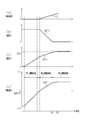
- (A) to (d) are timing charts when the vehicle is started.
- (A) to (d) are timing charts when the vehicle is started in the modified example.
- FIG. 1 shows a start control device 40, a braking device 20, and a drive device 30, which are examples of the control device of the present embodiment.
- the braking device 20 has a braking actuator 21 and a braking control unit 22 that controls the braking actuator 21.
- the braking control unit 22 adjusts the braking force BP of the vehicle by controlling the braking actuator 21.
- the drive device 30 has a power unit 31 and a drive control unit 32 that controls the power unit 31.
- the power unit 31 has an engine as a power source for the vehicle. Then, the drive control unit 32 adjusts the drive force DP of the vehicle by controlling the power unit 31.
- the vehicle is equipped with various sensors.
- the wheel speed sensor 101 can be mentioned.
- the wheel speed sensor 101 detects the wheel speed VW of the wheel 11 of the vehicle, and outputs a signal corresponding to the detected wheel speed VW to the start control device 40 as a detection signal.
- the vehicle body speed VS of the vehicle is derived based on the wheel speed VW of the wheels 11 based on the detection signal from the wheel speed sensor 101.
- the time-differentiated value of the vehicle body speed VS is derived as the vehicle body acceleration DVS of the vehicle.
- a start instruction of the stopped vehicle is input from another control device, and a required acceleration DVSR which is a required value of the vehicle body acceleration of the vehicle is input from the other control device.
- the start control device 40 is a functional unit that controls the braking device 20 and the drive device 30 when a vehicle start instruction is input, and is a target driving force setting unit 41, a first adjustment processing unit 42, and a second adjustment processing unit 43. It has a third adjustment processing unit 44, a start determination unit 45, and a target arrival determination unit 46.
- the target driving force setting unit 41 sets the target driving force DPS, which is the target of the driving force of the vehicle. That is, the target driving force setting unit 41 sets a value corresponding to the required acceleration DVSR as the target driving force DPS. Therefore, the target driving force DPS increases as the required acceleration DVSR increases.
- the first adjustment processing unit 42 performs the first adjustment processing for instructing at least one of the braking device 20 and the driving device 30 to increase the controlling driving force BDP when the vehicle is stopped by applying the braking force BP.
- the control driving force BDP is a force corresponding to the braking force BP and the driving force DP of the vehicle.
- the value obtained by subtracting the braking force BP from the driving force DP is the control driving force BDP. Therefore, when the braking force BP is higher than the driving force DP, the controlling driving force BDP is negative, while when the braking force BP is lower than the driving force DP, the controlling driving force BDP is positive.
- the controlling driving force BDP becomes "0 (zero)". The content of the first adjustment process will be described later.
- the second adjustment processing unit 43 starts the second adjustment processing when the predetermined first start condition is satisfied.
- the second adjustment processing unit 43 causes the braking device 20 and the driving device 30 to increase the controlling driving force BDP at a speed lower than the increasing speed of the controlling driving force BDP before the end of the first adjusting process. Instruct at least one of them.
- the content of the second adjustment process will be described later.
- the third adjustment processing unit 44 starts the third adjustment processing when the predetermined second start condition is satisfied.
- the third adjustment processing unit 44 causes the braking device 20 and the driving device 30 to increase the controlling driving force BDP at the same speed as the increasing speed of the controlling driving force BDP before the end of the second adjusting process. Instruct one of our devices. The content of the third adjustment process will be described later.
- the start determination unit 45 uses the detection signal from the wheel speed sensor 101 to determine whether or not the vehicle has started. That is, when it is detected that the wheel 11 is rotating based on the transition of the detection signal, the start determination unit 45 determines that the vehicle has started. On the other hand, if it is not detected that the wheels 11 are rotating, the start determination unit 45 does not determine that the vehicle has started.
- the target achievement determination unit 46 determines whether or not the braking force BP has reached the target value during the execution of the second adjustment process. That is, when the indicated braking force BPTr, which is the indicated value of the braking force output from the start control device 40 to the braking control unit 22, becomes equal to or less than the target braking force BPS, the target arrival determination unit 46 targets the braking force BP. It is determined that the value has been reached. In this embodiment, "0 (zero)" is set as the target braking force BPS. Therefore, when the indicated braking force BPTr becomes equal to or less than the target braking force BPS, it can be determined that the braking of the vehicle has been released.
- This processing routine is started on the condition that a start instruction is input to the start control device 40 while the vehicle is stopped.
- step S11 the sum of the current indicated driving force DPTr and the first driving increase amount ⁇ DP1 is calculated as the latest indicated driving force DPTr.
- step S12 the value obtained by subtracting the current indicated braking force BPTr from the latest indicated driving force DPTr is calculated as the controlling driving force BDP. Since the first adjustment process is started when the vehicle is stopped by applying the braking force BP, the indicated braking force BPTr is larger than the indicated driving force DPTr at the start of the first adjustment process. That is, at the start of the first adjustment process, the control driving force BDP is negative.
- an output process is executed in which the latest indicated driving force DPTr is input to the drive control unit 32 and the latest indicated braking force BPTr is input to the braking control unit 22.
- the drive control unit 32 controls the power unit 31 so that the driving force DP follows the indicated driving force DPTr. Therefore, by inputting an instruction based on the execution of the first adjustment process to the drive control unit 32, the driving force DP is increased at a speed corresponding to the first drive increase amount ⁇ DP1. Further, since the indicated braking force BPTr is held during the first adjustment process, the indicated braking force BPTr input to the braking control unit 22 does not change.
- the braking control unit 22 is instructed to hold the braking force BP.
- the braking control unit 22 controls the braking actuator 21 so as to hold the braking force BP by the indicated braking force BPTr. Therefore, during the first adjustment process, the control driving force BDP is increased at a speed corresponding to the first driving increase amount ⁇ DP1.
- step S14 it is determined whether or not the control driving force BDP is equal to or greater than the determination control driving force BDPTh.
- the determination driving force BDPTh is a criterion for determining whether or not the vehicle is about to start, and is set to a value smaller than "0 (zero)".
- the control driving force BDP is less than the determination control driving force BDPTh (S14: NO)
- the process proceeds to step S11 described above. That is, the first adjustment process is continued.
- step S15 it is determined whether or not the vehicle has started. That is, when the start determination unit 45 has not determined that the vehicle has started (S15: NO), the process proceeds to step S11 described above. That is, the first adjustment process is continued. On the other hand, when the start determination unit 45 determines that the vehicle has started (S15: YES), the first adjustment process is completed. Then, this processing routine is terminated.
- This processing routine is started on the condition that the control driving force BDP becomes equal to or higher than the determination control driving force BDPTh by executing the first adjustment process, and the start determination unit 45 determines that the vehicle has started. To. That is, when it is satisfied that the control driving force BDP becomes equal to or higher than the determination control driving force BDPTh by executing the first adjustment process, and that the start determination unit 45 determines that the vehicle has started. In addition, it can be determined that the first start condition is satisfied.
- step S21 the value obtained by subtracting the braking reduction amount ⁇ BP from the current indicated braking force BPTr is calculated as the latest indicated braking force BPTr.
- the braking reduction amount ⁇ BP is a positive value.
- step S22 the sum of the current indicated driving force DPTr and the second drive increasing amount ⁇ DP2 is calculated as a temporary value DPTr of the indicated driving force.
- the second drive increase amount ⁇ DP2 is a positive value and is smaller than the first drive increase amount ⁇ DP1. More specifically, the second drive increase amount ⁇ DP2 is set so that the sum of the second drive increase amount ⁇ DP2 and the braking decrease amount ⁇ BP is less than the first drive increase amount ⁇ DP1.
- step S23 the smaller of the calculated temporary value DPTr of the indicated driving force and the target driving force DPS set by the target driving force setting unit 41 is set as the latest indicated driving force DPTr.
- step S24 an output process is executed in which the latest indicated driving force DPTr is output to the drive control unit 32 and the latest indicated braking force BPTr is output to the braking control unit 22.
- the drive control unit 32 controls the power unit 31 so that the driving force DP follows the indicated driving force DPTr. Therefore, by inputting an instruction based on the execution of the second adjustment process to the drive control unit 32, the driving force DP is increased at a speed corresponding to the second drive increase amount ⁇ DP2. Further, when the indicated braking force BPTr is input by executing the output process, the braking control unit 22 controls the braking actuator 21 so that the braking force BP follows the indicated braking force BPTr. Therefore, by inputting an instruction based on the execution of the second adjustment process to the braking control unit 22, the braking force BP is reduced at a speed corresponding to the braking reduction amount ⁇ BP.
- step S25 it is determined whether or not the end condition of the second adjustment process is satisfied.
- the target arrival determination unit 46 determines that the braking force BP has reached the target value
- the target arrival determination unit 46 has not determined that the braking force BP has reached the target value
- the process proceeds to step S21 described above. That is, the second adjustment process is continued.
- the second adjustment process is terminated. Then, this processing routine is terminated.
- the sum of the braking decrease amount ⁇ BP and the second drive increase amount ⁇ DP2 is smaller than the first drive increase amount ⁇ DP1. Therefore, during the second adjustment process, the rate of increase of the control driving force BDP is lower than during the first adjustment process.
- This processing routine is started on the condition that the target arrival determination unit 46 determines that the braking force BP has reached the target value. That is, when it is determined by the target arrival determination unit 46 that the braking force BP has reached the target value, it can be determined that the second start condition is satisfied.
- step S31 the sum of the current indicated driving force DPTr and the third drive increasing amount ⁇ DP3 is calculated as a temporary value DPTrb of the indicated driving force.
- the third drive increase amount ⁇ DP3 is a positive value and is larger than the second drive increase amount ⁇ DP2.
- the third drive increase amount ⁇ DP3 is set so that the rate of increase of the control driving force BDP during the third adjustment process is the same as the rate of increase of the control drive force BDP during the second adjustment process.
- step S32 the smaller of the calculated temporary value DPTrb of the indicated driving force and the target driving force DPS set by the target driving force setting unit 41 is set as the latest indicated driving force DPTr.
- step S33 an output process for outputting the latest indicated driving force DPTr to the drive control unit 32 is executed.
- the drive control unit 32 controls the power unit 31 so that the driving force DP follows the indicated driving force DPTr. Therefore, by inputting an instruction based on the execution of the third adjustment process to the drive control unit 32, the driving force DP is increased at a speed corresponding to the third drive increase amount ⁇ DP3.
- step S34 it is determined whether or not the end condition of the third adjustment process is satisfied. For example, when the vehicle body speed VS becomes equal to or higher than the determined vehicle body speed VSTh, it is determined that the end condition has been completed. On the other hand, when the vehicle body speed VS is less than the determined vehicle body speed VSTh, it is not determined that the end condition has been completed.
- step S34: NO If it is not determined that the end condition is satisfied (S34: NO), the process proceeds to step S31 described above. That is, the third adjustment process is continued. On the other hand, when it is determined that the end condition is satisfied (S34: YES), the third adjustment process is terminated. Then, this processing routine is terminated.
- a start instruction is input to the start control device 40 at the timing T11 when the vehicle is stopped by applying the braking force BP.
- the first adjustment process is started.
- the indicated braking force BPTr is held, and the indicated driving force DPTr is increased at a speed corresponding to the first driving increase amount ⁇ DP1.
- the braking device 20 holds the braking force BP of the vehicle, while the driving device 30 increases the driving force DP of the vehicle so as to follow the increase of the indicated driving force DPTr.
- the control driving force BDP of the vehicle can be increased at a speed corresponding to the first drive increase amount ⁇ DP1.
- control driving force BDP becomes the judgment control driving force BDPTh or more at the timing T12 during the execution of the first adjustment process, it has not yet been determined that the vehicle has started at the timing T12. Therefore, the first adjustment process is continued. That is, the control driving force BDP continues to increase at a speed corresponding to the first driving increase amount ⁇ DP1. Since it is determined that the vehicle has started at the subsequent timing T13, the first adjustment process is completed and the second adjustment process is started.
- the control driving force BDP is increased at a higher speed than when the second adjustment process is executed. Therefore, the start instruction is compared with the case where the increase speed of the control driving force BDP during the execution of the first adjustment process is equal to the increase speed of the control drive force BDP during the execution of the second adjustment process, and the start instruction is the start control device. It is possible to shorten the time required from the input to 40 until the vehicle actually starts.
- the braking force BP is reduced during the execution of the first adjustment process.
- the braking force BP is reduced even when the difference between the driving force DP and the target driving force DPS is large. Therefore, for example, when the vehicle is stopped on an uphill road, the vehicle may slide down.
- the braking force BP is not reduced in the first adjustment process. Therefore, for example, even when the vehicle is stopped on an uphill road, it is possible to prevent the vehicle from sliding down during the execution of the first adjustment process.
- the indicated braking force BPTr is reduced at a speed corresponding to the braking reduction amount ⁇ BP. Further, in the second adjustment process, the indicated driving force DPTr is increased at a speed corresponding to the second driving increase amount ⁇ DP2. At this time, the instruction braking force BPTr and the instruction drive so that the increase speed of the control driving force BDP during the execution of the second adjustment process is lower than the increase rate of the control drive force BDP before the end of the first adjustment process. The force DPTr is changed.
- the vehicle accelerates rapidly after starting, as compared with the case where the increasing speed of the controlling driving force BDP during the execution of the second adjustment process is equal to the increasing speed of the controlling driving force BDP during the execution of the first adjustment process. Can be suppressed. Therefore, in the present embodiment, it is possible to suppress the sudden acceleration of the vehicle at the time of starting while suppressing the start delay of the vehicle.
- the braking force BP is reduced unlike the case where the first adjustment process is being executed. Therefore, the drag feeling of the vehicle can be reduced as compared with the case where the holding of the braking force BP is continued even during the execution of the second adjustment process.
- the indicated driving force DPTr does not exceed the target driving force DPS during the execution of the second adjustment process. Therefore, the instruction driving force DPTr is not held during the execution of the second adjustment process. However, depending on the required acceleration DVSR, the indicated driving force DPTr may reach the target driving force DPS during the execution of the second adjustment process. In this case, after the indicated driving force DPTr reaches the target driving force DPS, the indicated driving force DPTr is not increased even during the execution of the second adjustment process, that is, the indicated driving force DPTr is maintained.
- the braking force BP is not reduced during the execution of the third adjustment process, when the indicated driving force DPTr is increased at a speed corresponding to the second drive increase amount ⁇ DP2, it is controlled by the transition from the second adjustment process to the third adjustment process.
- the rate of increase of the driving force BDP becomes low.
- the driving force DP is increased at a speed corresponding to the third drive increase amount ⁇ DP3, which is larger than the second drive increase amount ⁇ DP2.
- the indicated driving force DPTr reaches the target driving force DPS at the timing T15 during the execution of the third adjustment process. Therefore, after the timing T15, the driving force DP and the controlling driving force BDP of the vehicle are maintained.
- the above embodiment can be modified and implemented as follows.
- the above-described embodiment and the following modified examples can be implemented in combination with each other within a technically consistent range.
- the rate of increase of the control driving force BDP during the third adjustment process is controlled during the second adjustment process. It is assumed to be the same as the rate of increase of the driving force BDP.
- the present invention is not limited to this, and the rate of increase of the controlling driving force BDP during the third adjustment process does not have to be the same as the rate of increase of the controlling driving force BDP during the second adjusting process.
- the rate of increase of the control driving force BDP during the third adjustment process may be lower than the rate of increase of the control drive force BDP during the second adjustment process.
- the third drive increase amount ⁇ DP3 is the second. It may be less than the drive increase amount ⁇ DP2, may be equal to the second drive increase amount ⁇ DP2, or may be larger than the second drive increase amount ⁇ DP2. In the example shown in FIG. 6, the third drive increase amount ⁇ DP3 is smaller than the second drive increase amount ⁇ DP2.
- the control driving force BDP increases from the start of the second adjustment process until the control driving force BDP is maintained because the indicated driving force DPTr reaches the target driving force DPS.
- the speed does not decrease. Therefore, the rate of increase of the control driving force BDP changes significantly before and after the timing T15 when the holding of the control driving force BDP is started. As a result, the acceleration of the vehicle may change significantly before and after the timing T15.
- the controlling driving force BDP is maintained because the indicated driving force DPTr reaches the target driving force DPS after the second adjustment process is started. The rate of increase in BDP is reduced once.
- the amount of change in the rate of increase of the control driving force BDP when the indicated driving force DPTr reaches the target driving force DPS can be made smaller than in the case of the example shown in FIG.
- the indicated braking force BPTr is performed in the first adjustment process. May be reduced.
- the indicated driving force DPTr may be changed or the indicated driving force DPTr may be held.
- the second drive increase in the second adjustment process It is not necessary to make the large amount ⁇ DP2 less than the first drive increase amount ⁇ DP1.
- the indicated driving force DPTr reaches the target driving force DPS before the indicated braking force BPTr reaches the target braking force BPS during the execution of the second adjustment process.
- the second adjustment process It may be determined that the end condition of is satisfied, the second adjustment process may be terminated, and the third adjustment process may be started.
- the decreasing speed of the indicated braking force BPTr in the third adjustment processing is set.
- the speed of decrease of the indicated braking force BPTr in the second adjustment process is increased.
- the third adjustment is performed.
- the rate of decrease of the indicated braking force BPTr in the process is set to be equal to or less than the rate of decrease of the indicated braking force BPTr in the second adjustment process.
- the first start condition may be a condition different from these conditions. For example, if the control driving force BDP becomes the determination control driving force BDPTh or more by executing the first adjustment process before the start determination unit 45 determines that the vehicle has started, the control driving force BDP is determined. It may be determined that the first start condition is satisfied when the control driving force BDPTh or more is satisfied, the first adjustment process may be terminated, and the second adjustment process may be started.
- the start determination unit 45 determines that the vehicle has started when the control driving force BDP is not equal to or higher than the determination control driving force BDPTh during the execution of the first adjustment process. It may be determined that the first start condition has been satisfied, the first adjustment process may be terminated, and the second adjustment process may be started.
- the start determination unit 45 may be omitted. In this case, regardless of whether the vehicle has started or not, when the control driving force BDP becomes equal to or higher than the judgment control driving force BDPTh by the execution of the first adjustment processing unit, the first adjustment process is terminated and the second adjustment is performed. The process will start.
- the judgment control driving force BDPTh is fixed at a specified value, but the judgment control driving force BDPTh may be changed. For example, if the slope of the road surface on which the vehicle is stopped can be obtained, the judgment-based driving force BDPTh is determined depending on whether the road surface is an uphill road, a downhill road, or a horizontal road surface. May be made variable. Further, the determination driving force BDPTh may be changed according to the slope of the road surface.
- the target braking force BPS is "0". (Zero) ”is set.
- the braking force BP of the vehicle can be reduced to a size that does not substantially affect the acceleration of the vehicle. Therefore, if it can be considered that the braking of the vehicle is released when the indicated braking force BPTr reaches the target braking force BPS, a value other than "0 (zero)” is set as the target braking force BPS. You may.
- the power unit may have both an engine and an electric motor as a power source for the vehicle. Further, the power unit may have only an electric motor as a power source of the vehicle.
- a target driving force setting unit for setting a value corresponding to the required acceleration as the target driving force which is the target of the driving force of the vehicle is provided.
- the second adjustment processing unit instructs the driving device to increase the driving force when the driving force of the vehicle is less than the target driving force, and the driving force of the vehicle is the target.
- the driving force it is preferable to instruct the driving device to hold the driving force.
- the third adjustment processing unit instructs the driving device to increase the driving force when the driving force of the vehicle is less than the target driving force, and the driving force of the vehicle.
- the target driving force it is preferable to instruct the driving device to hold the driving force.
Landscapes
- Engineering & Computer Science (AREA)
- Transportation (AREA)
- Mechanical Engineering (AREA)
- Automation & Control Theory (AREA)
- Chemical & Material Sciences (AREA)
- Combustion & Propulsion (AREA)
- Human Computer Interaction (AREA)
- Regulating Braking Force (AREA)
- Control Of Driving Devices And Active Controlling Of Vehicle (AREA)
Abstract
制御装置である発進制御装置(40)は、制駆動力が負であって車両が停止しているときに、制駆動力の増大を制動装置(20)及び駆動装置(30)のうちの少なくとも一方に指示する第1調整処理を実行する第1調整処理部(42)と、第1調整処理の実行に伴う制駆動力の増大によって制駆動力が判定制駆動力以上になったことを条件に、第1調処理の終了前での制駆動力の増大速度よりも低い速度での制駆動力の増大を制動装置(20)及び駆動装置(30)のうちの少なくとも一方に指示する第2調整処理を開始する第2調整処理部(43)とを備える。
Description
本発明は、車両の制動装置及び駆動装置を制御することによって車両を発進させる車両の制御装置に関する。
特許文献1には、車両の制動装置及び駆動装置を制御することによって車両を発進させる車両の制御装置の一例が記載されている。この制御装置では、制動力の付与によって車両が停止しているときに運転者によってアクセル操作が行われると、制動力を減少させるとともに駆動力を増大させる。そして、駆動力が制動力を上回ると、車両が発進する。
車両の制動力を減少させつつ駆動力を増大させることによって車両を発進させる場合、発進直後における制動力の減少態様や駆動力の増大態様によっては車両が急加速し、車両の乗員に不快感を与えてしまうおそれがある。
上記課題を解決するための車両の制御装置は、制動装置及び駆動装置を制御して車両を発進させる装置である。この制御装置は、前記車両の制動力が前記車両の駆動力を上回っているときには負となり、前記車両の制動力が前記車両の駆動力を下回っているときには正となる力を制駆動力とした場合、前記制駆動力が負であって前記車両が停止しているときに、前記制駆動力の増大を前記制動装置及び前記駆動装置のうちの少なくとも一方に指示する第1調整処理を実行する第1調整処理部と、前記第1調整処理の実行に伴う前記制駆動力の増大によって当該制駆動力が「0(零)」よりも小さい判定制駆動力以上になったことを条件に、前記第1調整処理の終了前での前記制駆動力の増大速度よりも低い速度での前記制駆動力の増大を前記制動装置及び前記駆動装置のうちの少なくとも一方に指示する第2調整処理を開始する第2調整処理部と、を備える。
上記構成によれば、制動力の付与によって車両が停止しているときに第1調整処理が実行されると、第1調整処理の指示によって制動装置及び駆動装置のうちの少なくとも一方の装置が駆動され、制駆動力が増大される。そして、制駆動力が判定駆動力以上であるときに、第1調整処理が終了されて第2調整処理が開始される。第2調整処理部の指示によって制動装置及び駆動装置のうちの少なくとも一方の装置が駆動されると、第1調整処理の終了前での制駆動力の増大速度よりも低い速度で制駆動力が増大されるようになる。すなわち、車両の発進前では比較的高い速度で制駆動力が増大され、車両の発進前後では比較的低い速度で制駆動力が増大される。これにより、車両の発進遅れを抑制しつつ、発進時における車両の急加速を抑制することができるようになる。
以下、車両の制御装置の一実施形態を図1~図5に従って説明する。
図1には、本実施形態の制御装置の一例である発進制御装置40と、制動装置20と、駆動装置30とが図示されている。制動装置20は、制動アクチュエータ21と、制動アクチュエータ21を制御する制動制御部22とを有している。制動制御部22は、制動アクチュエータ21を制御することによって車両の制動力BPを調整する。駆動装置30は、パワーユニット31と、パワーユニット31を制御する駆動制御部32とを有している。パワーユニット31は、車両の動力源としてエンジンを有している。そして、駆動制御部32は、パワーユニット31を制御することによって車両の駆動力DPを調整する。
図1には、本実施形態の制御装置の一例である発進制御装置40と、制動装置20と、駆動装置30とが図示されている。制動装置20は、制動アクチュエータ21と、制動アクチュエータ21を制御する制動制御部22とを有している。制動制御部22は、制動アクチュエータ21を制御することによって車両の制動力BPを調整する。駆動装置30は、パワーユニット31と、パワーユニット31を制御する駆動制御部32とを有している。パワーユニット31は、車両の動力源としてエンジンを有している。そして、駆動制御部32は、パワーユニット31を制御することによって車両の駆動力DPを調整する。
車両には、各種のセンサが設けられている。センサとして、例えば、車輪速度センサ101を挙げることができる。車輪速度センサ101は、車両の車輪11の車輪速度VWを検出し、検出した車輪速度VWに応じた信号を検出信号として発進制御装置40に出力する。発進制御装置40では、車輪速度センサ101からの検出信号に基づいた車輪11の車輪速度VWを基に、車両の車体速度VSが導出される。また、発進制御装置40では、車体速度VSを時間微分した値が車両の車体加速度DVSとして導出される。
また、発進制御装置40には、停止中の車両の発進指示が他の制御装置から入力されるとともに、車両の車体加速度の要求値である要求加速度DVSRが他の制御装置から入力される。発進制御装置40は、車両の発進指示が入力されたときに制動装置20及び駆動装置30を制御する機能部として、目標駆動力設定部41、第1調整処理部42、第2調整処理部43、第3調整処理部44、発進判定部45及び目標到達判定部46を有している。
目標駆動力設定部41は、車両の駆動力の目標である目標駆動力DPSを設定する。すなわち、目標駆動力設定部41は、目標駆動力DPSとして要求加速度DVSRに応じた値を設定する。そのため、目標駆動力DPSは、要求加速度DVSRが大きいほど大きくなる。
第1調整処理部42は、制動力BPの付与によって車両が停止しているときに、制駆動力BDPの増大を制動装置20及び駆動装置30のうちの少なくとも一方に指示する第1調整処理を実行する。制駆動力BDPとは、車両の制動力BPと駆動力DPとに応じた力である。例えば、駆動力DPから制動力BPを引いた値が制駆動力BDPである。そのため、制動力BPが駆動力DPを上回っているときには制駆動力BDPは負となる一方、制動力BPが駆動力DPを下回っているときには制駆動力BDPは正となる。制動力BPが駆動力DPと等しいときには制駆動力BDPが「0(零)」となる。第1調整処理の内容については後述する。
第2調整処理部43は、所定の第1開始条件が成立したことを契機に第2調整処理を開始する。第2調整処理部43は、第2調整処理では、第1調整処理の終了前での制駆動力BDPの増大速度よりも低い速度での制駆動力BDPの増大を制動装置20及び駆動装置30のうちの少なくとも一方に指示する。第2調整処理の内容については後述する。
第3調整処理部44は、所定の第2開始条件が成立したことを契機に第3調整処理を開始する。第3調整処理部44は、第3調整処理では、第2調整処理の終了前での制駆動力BDPの増大速度と同じ速度での制駆動力BDPの増大を制動装置20及び駆動装置30のうちの一方の装置に指示する。第3調整処理の内容については後述する。
発進判定部45は、車輪速度センサ101からの検出信号を用い、車両が発進したか否かの判定を行う。すなわち、検出信号の推移を基に車輪11が回転していることを検知した場合、発進判定部45は、車両が発進したとの判定をなす。一方、車輪11が回転していることを検知していない場合、発進判定部45は、車両が発進したとの判定をなさない。
目標到達判定部46は、第2調整処理の実行中に制動力BPが目標値に達したか否かを判定する。すなわち、目標到達判定部46は、発進制御装置40から制動制御部22に出力される制動力の指示値である指示制動力BPTrが目標制動力BPS以下になったときに、制動力BPが目標値に達したとの判定をなす。本実施形態では、目標制動力BPSとして「0(零)」が設定されている。そのため、指示制動力BPTrが目標制動力BPS以下になった場合には、車両の制動が解除されたと判定することもできる。
次に、図2を参照し、第1調整処理を実行するために第1調整処理部42が実行する処理ルーチンについて説明する。本処理ルーチンは、車両が停止している状況下において発進指示が発進制御装置40に入力されたことを条件に開始される。
本処理ルーチンにおいて、ステップS11では、現時点の指示駆動力DPTrと第1駆動増大量ΔDP1との和が最新の指示駆動力DPTrとして算出される。続いて、ステップS12において、最新の指示駆動力DPTrから現時点の指示制動力BPTrを引いた値が制駆動力BDPとして算出される。なお、制動力BPの付与によって車両が停止しているときに第1調整処理が開始されるため、第1調整処理の開始時では指示制動力BPTrが指示駆動力DPTrよりも大きい。つまり、第1調整処理の開始時では、制駆動力BDPは負である。
次のステップS13では、最新の指示駆動力DPTrを駆動制御部32に入力し、且つ、最新の指示制動力BPTrを制動制御部22に入力する出力処理が実行される。
なお、出力処理の実行によって指示駆動力DPTrが入力されると、駆動制御部32は、当該指示駆動力DPTrに駆動力DPが追随するようにパワーユニット31を制御する。そのため、第1調整処理の実行に基づいた指示が駆動制御部32に入力されることによって、第1駆動増大量ΔDP1に応じた速度で駆動力DPが増大される。また、第1調整処理中では指示制動力BPTrは保持されるため、制動制御部22に入力される指示制動力BPTrは変わらない。つまり、第1調整処理では、制動力BPの保持が制動制御部22に指示されることとなる。その結果、制動制御部22は、制動力BPを指示制動力BPTrで保持すべく制動アクチュエータ21を制御する。したがって、第1調整処理中では、第1駆動増大量ΔDP1に応じた速度で制駆動力BDPが増大されることとなる。
なお、出力処理の実行によって指示駆動力DPTrが入力されると、駆動制御部32は、当該指示駆動力DPTrに駆動力DPが追随するようにパワーユニット31を制御する。そのため、第1調整処理の実行に基づいた指示が駆動制御部32に入力されることによって、第1駆動増大量ΔDP1に応じた速度で駆動力DPが増大される。また、第1調整処理中では指示制動力BPTrは保持されるため、制動制御部22に入力される指示制動力BPTrは変わらない。つまり、第1調整処理では、制動力BPの保持が制動制御部22に指示されることとなる。その結果、制動制御部22は、制動力BPを指示制動力BPTrで保持すべく制動アクチュエータ21を制御する。したがって、第1調整処理中では、第1駆動増大量ΔDP1に応じた速度で制駆動力BDPが増大されることとなる。
出力処理が実行されると、処理が次のステップS14に移行される。ステップS14において、制駆動力BDPが判定制駆動力BDPTh以上であるか否かの判定が行われる。判定制駆動力BDPThは、車両が発進間近であるか否かの判断基準であり、「0(零)」よりも小さい値に設定されている。制駆動力BDPが判定制駆動力BDPTh未満である場合(S14:NO)、処理が前述したステップS11に移行される。すなわち、第1調整処理が継続される。
一方、制駆動力BDPが判定制駆動力BDPTh以上である場合(S14:YES)、処理が次のステップS15に移行される。ステップS15において、車両が発進したか否かの判定が行われる。すなわち、発進判定部45によって車両が発進したとの判定がなされていない場合(S15:NO)、処理が前述したステップS11に移行される。すなわち、第1調整処理が継続される。一方、発進判定部45によって車両が発進したとの判定がなされている場合(S15:YES)、第1調整処理が終了される。そして、本処理ルーチンが終了される。
次に、図3を参照し、第2調整処理を実行するために第2調整処理部43が実行する処理ルーチンについて説明する。本処理ルーチンは、第1調整処理の実行によって制駆動力BDPが判定制駆動力BDPTh以上になり、且つ、発進判定部45によって車両が発進したとの判定がなされていることを条件に開始される。すなわち、第1調整処理の実行によって制駆動力BDPが判定制駆動力BDPTh以上になること、及び、発進判定部45によって車両が発進したとの判定がなされていることの何れもが成立した場合に、上記第1開始条件が成立したと判断することができる。
本処理ルーチンにおいて、ステップS21では、現時点の指示制動力BPTrから制動減少量ΔBPを引いた値が最新の指示制動力BPTrとして算出される。制動減少量ΔBPは正の値である。続いて、ステップS22において、現時点の指示駆動力DPTrと第2駆動増大量ΔDP2との和が指示駆動力の仮値DPTraとして算出される。第2駆動増大量ΔDP2は、正の値であり、上記第1駆動増大量ΔDP1よりも少ない。より具体的には、第2駆動増大量ΔDP2は、第2駆動増大量ΔDP2と制動減少量ΔBPとの和が第1駆動増大量ΔDP1未満となるように設定されている。
そして、ステップS23において、算出した指示駆動力の仮値DPTraと、目標駆動力設定部41によって設定された目標駆動力DPSとのうちの小さい方が最新の指示駆動力DPTrとして設定される。続いて、次のステップS24において、最新の指示駆動力DPTrを駆動制御部32に出力し、且つ、最新の指示制動力BPTrを制動制御部22に出力する出力処理が実行される。
なお、出力処理の実行によって指示駆動力DPTrが入力されると、駆動制御部32は、当該指示駆動力DPTrに駆動力DPが追随するようにパワーユニット31を制御する。そのため、第2調整処理の実行に基づいた指示が駆動制御部32に入力されることによって、第2駆動増大量ΔDP2に応じた速度で駆動力DPが増大される。また、出力処理の実行によって指示制動力BPTrが入力されると、制動制御部22は、当該指示制動力BPTrに制動力BPが追随するように制動アクチュエータ21を制御する。そのため、第2調整処理の実行に基づいた指示が制動制御部22に入力されることによって、制動減少量ΔBPに応じた速度で制動力BPが減少される。
出力処理が実行されると、処理が次のステップS25に移行される。ステップS25において、第2調整処理の終了条件が成立しているか否かの判定が行われる。本実施形態では、目標到達判定部46によって制動力BPが目標値に達したとの判定がなされている場合、第2調整処理の終了条件が成立したとの判定がなされる。一方、目標到達判定部46によって制動力BPが目標値に達したとの判定がなされていない場合、第2調整処理の終了条件が成立したとの判定がなされない。そして、終了条件が成立しているとの判定がなされていない場合(S25:NO)、処理が前述したステップS21に移行される。すなわち、第2調整処理が継続される。一方、終了条件が成立しているとの判定がなされている場合(S25:YES)、第2調整処理が終了される。そして、本処理ルーチンが終了される。
上述したように、制動減少量ΔBPと第2駆動増大量ΔDP2との和は第1駆動増大量ΔDP1よりも少ない。そのため、第2調整処理中では、制駆動力BDPの増大速度が第1調整処理中よりも低い。
次に、図4を参照し、第3調整処理を実行するために第3調整処理部44が実行する処理ルーチンについて説明する。本処理ルーチンは、目標到達判定部46によって制動力BPが目標値に達したとの判定がなされていることを条件に開始される。すなわち、目標到達判定部46によって制動力BPが目標値に達したとの判定がなされている場合に、上記第2開始条件が成立したと判断することができる。
本処理ルーチンにおいて、ステップS31では、現時点の指示駆動力DPTrと第3駆動増大量ΔDP3との和が指示駆動力の仮値DPTrbとして算出される。第3駆動増大量ΔDP3は、正の値であり、第2駆動増大量ΔDP2よりも多い。具体的には、第3調整処理中での制駆動力BDPの増大速度が第2調整処理中での制駆動力BDPの増大速度と同じとなるように、第3駆動増大量ΔDP3が設定される。続いて、ステップS32において、算出した指示駆動力の仮値DPTrbと、目標駆動力設定部41によって設定された目標駆動力DPSとのうちの小さい方が最新の指示駆動力DPTrとして設定される。そして、ステップS33において、最新の指示駆動力DPTrを駆動制御部32に出力する出力処理が実行される。
なお、出力処理の実行によって指示駆動力DPTrが入力されると、駆動制御部32は、当該指示駆動力DPTrに駆動力DPが追随するようにパワーユニット31を制御する。そのため、第3調整処理の実行に基づいた指示が駆動制御部32に入力されることによって、第3駆動増大量ΔDP3に応じた速度で駆動力DPが増大される。
出力処理が実行されると、処理が次のステップS34に移行される。ステップS34において、第3調整処理の終了条件が成立しているか否かの判定が行われる。例えば、車両の車体速度VSが判定車体速度VSTh以上になった場合、終了条件が終了したとの判定がなされる。一方、車体速度VSが判定車体速度VSTh未満である場合、終了条件が終了したとの判定がなされない。
終了条件が成立したとの判定がなされていない場合(S34:NO)、処理が前述したステップS31に移行される。すなわち、第3調整処理が継続される。一方、終了条件が成立したとの判定がなされている場合(S34:YES)、第3調整処理が終了される。そして、本処理ルーチンが終了される。
次に、図5を参照し、本実施形態の作用及び効果について説明する。
図5(a),(b),(c),(d)に示すように、制動力BPの付与によって車両が停止しているタイミングT11に発進指示が発進制御装置40に入力される。すると、第1調整処理が開始される。第1調整処理では、指示制動力BPTrが保持された上で、第1駆動増大量ΔDP1に応じた速度で指示駆動力DPTrが増大される。すると、制動装置20は車両の制動力BPを保持する一方、駆動装置30は指示駆動力DPTrの増大に追随するように車両の駆動力DPを増大させる。これにより、第1駆動増大量ΔDP1に応じた速度で車両の制駆動力BDPを増大させることができる。
図5(a),(b),(c),(d)に示すように、制動力BPの付与によって車両が停止しているタイミングT11に発進指示が発進制御装置40に入力される。すると、第1調整処理が開始される。第1調整処理では、指示制動力BPTrが保持された上で、第1駆動増大量ΔDP1に応じた速度で指示駆動力DPTrが増大される。すると、制動装置20は車両の制動力BPを保持する一方、駆動装置30は指示駆動力DPTrの増大に追随するように車両の駆動力DPを増大させる。これにより、第1駆動増大量ΔDP1に応じた速度で車両の制駆動力BDPを増大させることができる。
第1調整処理の実行中のタイミングT12で制駆動力BDPが判定制駆動力BDPTh以上になるものの、タイミングT12では車両が発進したとの判定が未だなされていない。そのため、第1調整処理が継続される。すなわち、第1駆動増大量ΔDP1に応じた速度での制駆動力BDPの増大が継続される。その後のタイミングT13で車両が発進したとの判定がなされるため、第1調整処理が終了されて第2調整処理が開始される。
第1調整処理の実行中では、第2調整処理の実行時よりも高い速度で制駆動力BDPが増大される。そのため、第1調整処理の実行中の制駆動力BDPの増大速度を、第2調整処理の実行中での制駆動力BDPの増大速度と同等とする場合と比較し、発進指示が発進制御装置40に入力されてから車両が実際に発進するまでに要する時間を短縮することができる。
また、第1調整処理の実行中に制動力BPを減少させる比較例について考える。この比較例では、駆動力DPと目標駆動力DPSとの乖離が大きい状態でも制動力BPが減少されることとなる。そのため、例えば車両が登坂路で停止していた場合、車両のずり下がりが発生するおそれがある。これに対し、本実施形態では、第1調整処理では、制動力BPが減少されない。そのため、例えば車両が登坂路に停止していた場合であっても第1調整処理の実行中に車両のずり下がりが発生することを抑制できる。
タイミングT13から第2調整処理が開始されると、制動減少量ΔBPに応じた速度で指示制動力BPTrが減少される。また、第2調整処理では、第2駆動増大量ΔDP2に応じた速度で指示駆動力DPTrが増大される。この際、第2調整処理の実行中での制駆動力BDPの増大速度が第1調整処理の終了前での制駆動力BDPの増大速度よりも低くなるように、指示制動力BPTr及び指示駆動力DPTrが変更される。そのため、第2調整処理の実行中での制駆動力BDPの増大速度を第1調整処理の実行中での制駆動力BDPの増大速度と同等とする場合と比較し、発進後に車両が急加速することを抑制できる。したがって、本実施形態では、車両の発進遅れを抑制しつつ、発進時における車両の急加速を抑制することができる。
また、第2調整処理では、第1調整処理の実行中とは異なり、制動力BPが減少される。そのため、第2調整処理の実行中でも制動力BPの保持が継続される場合と比較し、車両の引きずり感を低減させることができる。
なお、図5に示す例では、第2調整処理の実行中に指示駆動力DPTrが目標駆動力DPS以上になることはない。そのため、第2調整処理の実行中に指示駆動力DPTrが保持されることはない。しかし、要求加速度DVSRによっては第2調整処理の実行中に、指示駆動力DPTrが目標駆動力DPSに達することがある。この場合、指示駆動力DPTrが目標駆動力DPSに達した以降にあっては、第2調整処理の実行中でも指示駆動力DPTrが増大されなくなる、すなわち指示駆動力DPTrが保持される。
第2調整処理の実行中のタイミングT14で指示制動力BPTrが目標制動力BPS(=0(零))となり、制動力BPが目標値に達したとの判定がなされる。そのため、第2調整処理が終了されて第3調整処理が開始される。第3調整処理の実行中では、制動力BPをこれ以上減少させることができないため、第2駆動増大量ΔDP2よりも多い第3駆動増大量ΔDP3に応じた速度で指示駆動力DPTrが増大されるようになる。
第3調整処理の実行中では制動力BPが減少されないため、第2駆動増大量ΔDP2に応じた速度で指示駆動力DPTrを増大させた場合、第2調整処理から第3調整処理の移行によって制駆動力BDPの増大速度が低くなる。この点、本実施形態において第3調整処理の実行中では、第2駆動増大量ΔDP2よりも多い第3駆動増大量ΔDP3に応じた速度で駆動力DPが増大される。これにより、第2調整処理から第3調整処理の移行に起因する制駆動力BDPの増大速度の変化を抑制することができる。その結果、第2調整処理から第3調整処理の移行に起因した車両の加速度の変化を抑制することができる。
なお、図5に示す例では、第3調整処理の実行中のタイミングT15で指示駆動力DPTrが目標駆動力DPSに達する。そのため、タイミングT15以降では、車両の駆動力DP及び制駆動力BDPが保持される。
上記実施形態は、以下のように変更して実施することができる。上記実施形態及び以下の変更例は、技術的に矛盾しない範囲で互いに組み合わせて実施することができる。
・上記実施形態では、第3駆動増大量ΔDP3を第2駆動増大量ΔDP2よりも多くすることによって、第3調整処理中での制駆動力BDPの増大速度を、第2調整処理中での制駆動力BDPの増大速度と同じとしている。しかし、これに限らず、第3調整処理中での制駆動力BDPの増大速度を、第2調整処理中での制駆動力BDPの増大速度と同じとしなくてもよい。例えば、第3調整処理中での制駆動力BDPの増大速度を、第2調整処理中での制駆動力BDPの増大速度よりも低くしてもよい。
・上記実施形態では、第3駆動増大量ΔDP3を第2駆動増大量ΔDP2よりも多くすることによって、第3調整処理中での制駆動力BDPの増大速度を、第2調整処理中での制駆動力BDPの増大速度と同じとしている。しかし、これに限らず、第3調整処理中での制駆動力BDPの増大速度を、第2調整処理中での制駆動力BDPの増大速度と同じとしなくてもよい。例えば、第3調整処理中での制駆動力BDPの増大速度を、第2調整処理中での制駆動力BDPの増大速度よりも低くしてもよい。
図6(a),(b),(c),(d)には、第3調整処理中での制駆動力BDPの増大速度を、第2調整処理中での制駆動力BDPの増大速度よりも低くする場合の一例が図示されている。この場合、第3調整処理中での制駆動力BDPの増大速度が第2調整処理中での制駆動力BDPの増大速度よりも低くなるのであれば、第3駆動増大量ΔDP3は、第2駆動増大量ΔDP2よりも少なくてもよいし、第2駆動増大量ΔDP2と等しくてもよいし、第2駆動増大量ΔDP2よりも多くてもよい。図6に示す例では、第3駆動増大量ΔDP3は、第2駆動増大量ΔDP2よりも少ない。
タイミングT21で第2調整処理の実行によって指示制動力BPTrが目標制動力BPS(=0(零))となり、制動力BPが目標値に達したとの判定がなされる。そのため、タイミングT21で第2調整処理が終了されて第3調整処理が開始される。このとき、タイミングT21以降での制駆動力BDPの増大速度、すなわち駆動力DPの増大速度が、タイミングT21以前での制駆動力BDPの増大速度よりも低くなる。そして、第3調整処理の実行中におけるタイミングT22で指示駆動力DPTrが目標駆動力DPSに達するため、タイミングT22以降では制駆動力BDPが保持される。
図5に示した例では、第2調整処理が開始されてから、指示駆動力DPTrが目標駆動力DPSに達したために制駆動力BDPが保持されるまでの間で、制駆動力BDPの増大速度が低くならない。そのため、制駆動力BDPの保持が開始されるタイミングT15の前後で制駆動力BDPの増大速度が大きく変化する。その結果、タイミングT15の前後で車両の加速度が大きく変わるおそれがある。これに対し、図6に示す例では、第2調整処理が開始されてから、指示駆動力DPTrが目標駆動力DPSに達したために制駆動力BDPが保持されるまでの間で、制駆動力BDPの増大速度が一度減少される。そのため、指示駆動力DPTrが目標駆動力DPSに達した際における制駆動力BDPの増大速度の変化量を、図5に示した例の場合よりも小さくすることができる。図6に示す例のように制駆動力BDPの増大速度の減少を複数回に分けて行うことにより、車両の加速度が大きく変化することを抑制できる。
・第1調整処理の実行中における制駆動力BDPの増大速度を第2調整処理の実行中における制駆動力BDPの増大速度よりも高くできるのであれば、第1調整処理で、指示制動力BPTrを減少させるようにしてもよい。このように第1調整処理で指示制動力BPTrを減少させる場合、指示駆動力DPTrを可変させてもよいし、指示駆動力DPTrを保持するようにしてもよい。ただし、第1調整処理の実行に伴う制動力BPの減少によって車両のずり下がりの発生が予測されるときには、第1調整処理で指示制動力BPTrを減少させないようにすることが望ましい。
・第2調整処理の実行中における制駆動力BDPの増大速度を第1調整処理の実行中における制駆動力BDPの増大速度よりも低くできるのであれば、第2調整処理で、第2駆動増大量ΔDP2を第1駆動増大量ΔDP1よりも少なくしなくてもよい。
・路面勾配θが小さいために目標駆動力DPSが小さい場合、第2調整処理の実行中では、指示制動力BPTrが目標制動力BPSに達する前に、指示駆動力DPTrが目標駆動力DPSに達することもある。このような場合、第2調整処理中において指示駆動力DPTrが目標駆動力DPSに達した場合には、駆動力DPが目標値に達したとの判定をなすことができるため、第2調整処理の終了条件が成立したと判定し、第2調整処理を終了して第3調整処理を開始させるようにしてもよい。第3調整処理中での制駆動力BDPの増大速度を、第2調整処理中での制駆動力BDPの増大速度と同じとする場合、第3調整処理での指示制動力BPTrの減少速度を、第2調整処理での指示制動力BPTrの減少速度より高くする。
また、図6に示した例のように第3調整処理中での制駆動力BDPの増大速度を、第2調整処理中での制駆動力BDPの増大速度よりも低くする場合、第3調整処理での指示制動力BPTrの減少速度を第2調整処理での指示制動力BPTrの減少速度以下とする。
・上記実施形態では、第1調整処理の実行によって制駆動力BDPが判定制駆動力BDPTh以上になること、及び、発進判定部45によって車両が発進したとの判定がなされていることの何れもが成立した場合に、上記第1開始条件が成立したと判断し、第1調整処理を終了して第2調整処理を開始するようにしている。しかし、第1開始条件は、こうした条件とは別の条件であってもよい。例えば、発進判定部45によって車両が発進したとの判定がなされる前に第1調整処理の実行によって制駆動力BDPが判定制駆動力BDPTh以上になった場合には、制駆動力BDPが判定制駆動力BDPTh以上になったことをもって第1開始条件が成立したと判断し、第1調整処理を終了して第2調整処理を開始するようにしてもよい。反対に、第1調整処理の実行中で制駆動力BDPが判定制駆動力BDPTh以上になっていない段階で発進判定部45によって車両が発進したとの判定がなされた場合には、当該判定がなされたことをもって第1開始条件が成立したと判断し、第1調整処理を終了して第2調整処理を開始するようにしてもよい。
・発進判定部45を省略してもよい。この場合、車両が発進したか否かに拘わらず、第1調整処理部の実行によって制駆動力BDPが判定制駆動力BDPTh以上になったときに、第1調整処理を終了して第2調整処理を開始することになる。
・上記実施形態では、判定制駆動力BDPThを規定値で固定しているが、判定制駆動力BDPThを可変させるようにしてもよい。例えば、車両の停止している路面の勾配を取得できるのであれば、路面が登坂路であるか、路面が降坂路であるのか、又は、路面が水平路であるかによって、判定制駆動力BDPThを可変させるようにしてもよい。また、路面の勾配に応じて判定制駆動力BDPThを可変させるようにしてもよい。
・上記実施形態では、指示制動力BPTrを「0(零)」とすることによって制動力BPが「0(零)」となって車両の制動が解除されるため、目標制動力BPSとして「0(零)」が設定されている。しかし、指示制動力BPTrを「0(零)」まで減少させなくても、車両の加速に実質的に影響がない大きさまで車両の制動力BPを小さくすることもできる。そのため、指示制動力BPTrが目標制動力BPSに達したときに車両の制動が解除されたと見なすことができるのであれば、目標制動力BPSとして「0(零)」以外の値を設定するようにしてもよい。
・パワーユニットは、車両の動力源としてエンジン及び電気モータの双方を有するものであってもよい。また、パワーユニットは、車両の動力源として電気モータのみを有するものであってもよい。
次に、上記実施形態及び変更例から把握できる技術的思想について記載する。
(イ)前記車両に要求されている車体加速度を要求加速度とした場合、前記車両の駆動力の目標である目標駆動力として前記要求加速度に応じた値を設定する目標駆動力設定部を備え、
前記第2調整処理部は、前記第2調整処理では、前記車両の駆動力が前記目標駆動力未満であるときには当該駆動力の増大を前記駆動装置に指示し、前記車両の駆動力が前記目標駆動力に達したときには当該駆動力の保持を前記駆動装置に指示することが好ましい。
(イ)前記車両に要求されている車体加速度を要求加速度とした場合、前記車両の駆動力の目標である目標駆動力として前記要求加速度に応じた値を設定する目標駆動力設定部を備え、
前記第2調整処理部は、前記第2調整処理では、前記車両の駆動力が前記目標駆動力未満であるときには当該駆動力の増大を前記駆動装置に指示し、前記車両の駆動力が前記目標駆動力に達したときには当該駆動力の保持を前記駆動装置に指示することが好ましい。
(ロ)前記第3調整処理部は、前記第3調整処理では、前記車両の駆動力が前記目標駆動力未満であるときには当該駆動力の増大を前記駆動装置に指示し、前記車両の駆動力が前記目標駆動力に達したときには当該駆動力の保持を前記駆動装置に指示することが好ましい。
Claims (4)
- 制動装置及び駆動装置を制御して車両を発進させる車両の制御装置であって、
前記車両の制動力が前記車両の駆動力を上回っているときには負となり、前記車両の制動力が前記車両の駆動力を下回っているときには正となる力を制駆動力とした場合、
前記制駆動力が負であって前記車両が停止しているときに、前記制駆動力の増大を前記制動装置及び前記駆動装置のうちの少なくとも一方に指示する第1調整処理を実行する第1調整処理部と、
前記第1調整処理の実行に伴う前記制駆動力の増大によって当該制駆動力が「0(零)」よりも小さい判定制駆動力以上になったことを条件に、前記第1調整処理の終了前での前記制駆動力の増大速度よりも低い速度での前記制駆動力の増大を前記制動装置及び前記駆動装置のうちの少なくとも一方に指示する第2調整処理を開始する第2調整処理部と、を備える
車両の制御装置。 - 前記車両が発進したか否かを判定する発進判定部を備え、
前記第2調整処理部は、前記制駆動力が前記判定制駆動力以上であって、且つ、前記車両が発進したとの判定がなされていることを条件に、前記第2調整処理を開始する
請求項1に記載の車両の制御装置。 - 前記第2調整処理の実行中に前記車両の制動力及び駆動力のうちの一方の力が目標値に達したか否かを判定する目標到達判定部と、
前記一方の力が前記目標値に達したとの判定がなされていることを条件に、前記制駆動力の増大を前記制動装置及び前記駆動装置のうちの一方の装置に指示する第3調整処理を開始する第3調整処理部と、を備え、
前記第3調整処理部は、前記第3調整処理では、前記第2調整処理の終了前での前記制駆動力の増大速度と同じ速度での前記制駆動力の増大を前記一方の装置に指示する
請求項1又は請求項2に記載の車両の制御装置。 - 前記第2調整処理の実行中に前記車両の制動力及び駆動力のうちの一方の力が目標値に達したか否かを判定する目標到達判定部と、
前記一方の力が前記目標値に達したとの判定がなされていることを条件に、前記制駆動力の増大を前記制動装置及び前記駆動装置のうちの一方の装置に指示する第3調整処理を開始する第3調整処理部と、を備え、
前記第3調整処理部は、前記第3調整処理では、前記第2調整処理の終了前での前記制駆動力の増大速度よりも低速での前記制駆動力の増大を前記一方の装置に指示する
請求項1又は請求項2に記載の車両の制御装置。
Priority Applications (1)
| Application Number | Priority Date | Filing Date | Title |
|---|---|---|---|
| US17/439,618 US11878690B2 (en) | 2019-03-29 | 2020-03-11 | Vehicle control device |
Applications Claiming Priority (2)
| Application Number | Priority Date | Filing Date | Title |
|---|---|---|---|
| JP2019065367A JP7236308B2 (ja) | 2019-03-29 | 2019-03-29 | 車両の制御装置 |
| JP2019-065367 | 2019-03-29 |
Publications (1)
| Publication Number | Publication Date |
|---|---|
| WO2020203121A1 true WO2020203121A1 (ja) | 2020-10-08 |
Family
ID=72668680
Family Applications (1)
| Application Number | Title | Priority Date | Filing Date |
|---|---|---|---|
| PCT/JP2020/010545 Ceased WO2020203121A1 (ja) | 2019-03-29 | 2020-03-11 | 車両の制御装置 |
Country Status (3)
| Country | Link |
|---|---|
| US (1) | US11878690B2 (ja) |
| JP (1) | JP7236308B2 (ja) |
| WO (1) | WO2020203121A1 (ja) |
Families Citing this family (1)
| Publication number | Priority date | Publication date | Assignee | Title |
|---|---|---|---|---|
| JP7136378B1 (ja) | 2020-09-29 | 2022-09-13 | 日本精工株式会社 | 状態診断方法、状態診断装置、およびプログラム |
Citations (3)
| Publication number | Priority date | Publication date | Assignee | Title |
|---|---|---|---|---|
| JP2008001288A (ja) * | 2006-06-23 | 2008-01-10 | Advics:Kk | 車両の自動制動力制御装置 |
| JP2010221917A (ja) * | 2009-03-24 | 2010-10-07 | Hitachi Automotive Systems Ltd | 車両制御装置 |
| JP2014054945A (ja) * | 2012-09-13 | 2014-03-27 | Mitsubishi Motors Corp | 車両制御装置 |
Family Cites Families (15)
| Publication number | Priority date | Publication date | Assignee | Title |
|---|---|---|---|---|
| JP3138603B2 (ja) * | 1994-11-30 | 2001-02-26 | 三菱電機株式会社 | アンチスキッド制御装置 |
| JP2002104156A (ja) * | 2000-09-27 | 2002-04-10 | Toyota Motor Corp | 車輌の制駆動力制御装置 |
| JP4186081B2 (ja) * | 2005-02-02 | 2008-11-26 | トヨタ自動車株式会社 | 車輌の制駆動力制御装置 |
| JP4557962B2 (ja) * | 2006-12-28 | 2010-10-06 | トヨタ自動車株式会社 | 内燃機関の制御装置 |
| JP2009062846A (ja) | 2007-09-05 | 2009-03-26 | Toyota Motor Corp | 運転者の発進準備を感知して駆動制御を行う車輌 |
| JP4912257B2 (ja) * | 2007-09-06 | 2012-04-11 | トヨタ自動車株式会社 | 車両走行制御装置 |
| JP5471429B2 (ja) * | 2009-12-25 | 2014-04-16 | 株式会社アドヴィックス | 車両の停止制御装置及び車両の停止制御方法 |
| US9676289B2 (en) * | 2013-10-11 | 2017-06-13 | Ford Global Technologies, Llc | System and method for adjusting battery pack state of charge thresholds |
| JP6164140B2 (ja) * | 2014-03-31 | 2017-07-19 | 株式会社アドヴィックス | 車両の運転支援装置 |
| JP6156270B2 (ja) * | 2014-06-30 | 2017-07-05 | 株式会社アドヴィックス | 車両制動装置 |
| JP6292161B2 (ja) * | 2015-04-20 | 2018-03-14 | トヨタ自動車株式会社 | 制動力制御装置 |
| JP6764312B2 (ja) * | 2016-10-19 | 2020-09-30 | 日立オートモティブシステムズ株式会社 | 車両運動制御装置、車両運動制御方法、車両運動制御プログラム |
| JP6944130B2 (ja) * | 2018-03-19 | 2021-10-06 | トヨタ自動車株式会社 | 車両の姿勢制御装置 |
| JP7127522B2 (ja) * | 2018-12-17 | 2022-08-30 | トヨタ自動車株式会社 | 車両用制動力制御装置 |
| JP7147585B2 (ja) * | 2019-01-23 | 2022-10-05 | トヨタ自動車株式会社 | 車両制御装置 |
-
2019
- 2019-03-29 JP JP2019065367A patent/JP7236308B2/ja active Active
-
2020
- 2020-03-11 US US17/439,618 patent/US11878690B2/en active Active
- 2020-03-11 WO PCT/JP2020/010545 patent/WO2020203121A1/ja not_active Ceased
Patent Citations (3)
| Publication number | Priority date | Publication date | Assignee | Title |
|---|---|---|---|---|
| JP2008001288A (ja) * | 2006-06-23 | 2008-01-10 | Advics:Kk | 車両の自動制動力制御装置 |
| JP2010221917A (ja) * | 2009-03-24 | 2010-10-07 | Hitachi Automotive Systems Ltd | 車両制御装置 |
| JP2014054945A (ja) * | 2012-09-13 | 2014-03-27 | Mitsubishi Motors Corp | 車両制御装置 |
Also Published As
| Publication number | Publication date |
|---|---|
| US20220153271A1 (en) | 2022-05-19 |
| JP2020163961A (ja) | 2020-10-08 |
| JP7236308B2 (ja) | 2023-03-09 |
| US11878690B2 (en) | 2024-01-23 |
Similar Documents
| Publication | Publication Date | Title |
|---|---|---|
| KR101694074B1 (ko) | 하이브리드 dct 차량의 변속 제어방법 | |
| TW201924975A (zh) | 電動車輛巡航控制方法和系統及車輛、控制器和儲存媒體 | |
| US9079502B2 (en) | Electrically driven vehicle | |
| JP2019199129A (ja) | 車両走行制御装置 | |
| US10358137B2 (en) | Vehicle control device and vehicle control method | |
| JP7359318B2 (ja) | 駆動力制御方法及び駆動力制御装置 | |
| KR101484213B1 (ko) | 모터 토크 제어장치 및 제어방법 | |
| CN100363213C (zh) | 车辆制动力控制装置和车辆制动力控制方法 | |
| CN110550003B (zh) | 驾驶辅助装置 | |
| JP2017158337A (ja) | 電動車両の制御装置、電動車両の制御システムおよび電動車両の制御方法 | |
| WO2020175133A1 (ja) | 車両の制動制御装置 | |
| JP6164141B2 (ja) | 車両の運転支援装置 | |
| JP7236308B2 (ja) | 車両の制御装置 | |
| JP7131144B2 (ja) | 車両の駆動システムに適用される駆動制御装置 | |
| JP7505610B2 (ja) | 車両の制御装置 | |
| JP6164140B2 (ja) | 車両の運転支援装置 | |
| CN115817450A (zh) | 车辆用控制装置以及车辆用控制方法 | |
| JP4346089B2 (ja) | 車両の運動状態制御装置 | |
| JP7279279B2 (ja) | 制動制御装置 | |
| US10974563B2 (en) | Control of a suspension component of a vehicle | |
| JP2010196848A (ja) | 電動車両の制御装置 | |
| JP6387675B2 (ja) | 車両のトラクション制御装置 | |
| JP6464702B2 (ja) | 車両の運転支援装置 | |
| JP2026048288A (ja) | 車両の制御システム及び制御方法 | |
| WO2025243513A1 (ja) | 電動車両の制御方法、及び、電動車両の制御装置 |
Legal Events
| Date | Code | Title | Description |
|---|---|---|---|
| 121 | Ep: the epo has been informed by wipo that ep was designated in this application |
Ref document number: 20782780 Country of ref document: EP Kind code of ref document: A1 |
|
| NENP | Non-entry into the national phase |
Ref country code: DE |
|
| 122 | Ep: pct application non-entry in european phase |
Ref document number: 20782780 Country of ref document: EP Kind code of ref document: A1 |