WO2020203054A1 - 車両走行制御装置 - Google Patents
車両走行制御装置 Download PDFInfo
- Publication number
- WO2020203054A1 WO2020203054A1 PCT/JP2020/009774 JP2020009774W WO2020203054A1 WO 2020203054 A1 WO2020203054 A1 WO 2020203054A1 JP 2020009774 W JP2020009774 W JP 2020009774W WO 2020203054 A1 WO2020203054 A1 WO 2020203054A1
- Authority
- WO
- WIPO (PCT)
- Prior art keywords
- vehicle
- unit
- route
- control device
- control
- Prior art date
Links
Images


Classifications
-
- B—PERFORMING OPERATIONS; TRANSPORTING
- B60—VEHICLES IN GENERAL
- B60W—CONJOINT CONTROL OF VEHICLE SUB-UNITS OF DIFFERENT TYPE OR DIFFERENT FUNCTION; CONTROL SYSTEMS SPECIALLY ADAPTED FOR HYBRID VEHICLES; ROAD VEHICLE DRIVE CONTROL SYSTEMS FOR PURPOSES NOT RELATED TO THE CONTROL OF A PARTICULAR SUB-UNIT
- B60W30/00—Purposes of road vehicle drive control systems not related to the control of a particular sub-unit, e.g. of systems using conjoint control of vehicle sub-units, or advanced driver assistance systems for ensuring comfort, stability and safety or drive control systems for propelling or retarding the vehicle
- B60W30/14—Adaptive cruise control
-
- B—PERFORMING OPERATIONS; TRANSPORTING
- B60—VEHICLES IN GENERAL
- B60W—CONJOINT CONTROL OF VEHICLE SUB-UNITS OF DIFFERENT TYPE OR DIFFERENT FUNCTION; CONTROL SYSTEMS SPECIALLY ADAPTED FOR HYBRID VEHICLES; ROAD VEHICLE DRIVE CONTROL SYSTEMS FOR PURPOSES NOT RELATED TO THE CONTROL OF A PARTICULAR SUB-UNIT
- B60W60/00—Drive control systems specially adapted for autonomous road vehicles
- B60W60/001—Planning or execution of driving tasks
- B60W60/0015—Planning or execution of driving tasks specially adapted for safety
- B60W60/0016—Planning or execution of driving tasks specially adapted for safety of the vehicle or its occupants
-
- B—PERFORMING OPERATIONS; TRANSPORTING
- B60—VEHICLES IN GENERAL
- B60W—CONJOINT CONTROL OF VEHICLE SUB-UNITS OF DIFFERENT TYPE OR DIFFERENT FUNCTION; CONTROL SYSTEMS SPECIALLY ADAPTED FOR HYBRID VEHICLES; ROAD VEHICLE DRIVE CONTROL SYSTEMS FOR PURPOSES NOT RELATED TO THE CONTROL OF A PARTICULAR SUB-UNIT
- B60W40/00—Estimation or calculation of non-directly measurable driving parameters for road vehicle drive control systems not related to the control of a particular sub unit, e.g. by using mathematical models
- B60W40/08—Estimation or calculation of non-directly measurable driving parameters for road vehicle drive control systems not related to the control of a particular sub unit, e.g. by using mathematical models related to drivers or passengers
-
- B—PERFORMING OPERATIONS; TRANSPORTING
- B60—VEHICLES IN GENERAL
- B60W—CONJOINT CONTROL OF VEHICLE SUB-UNITS OF DIFFERENT TYPE OR DIFFERENT FUNCTION; CONTROL SYSTEMS SPECIALLY ADAPTED FOR HYBRID VEHICLES; ROAD VEHICLE DRIVE CONTROL SYSTEMS FOR PURPOSES NOT RELATED TO THE CONTROL OF A PARTICULAR SUB-UNIT
- B60W50/00—Details of control systems for road vehicle drive control not related to the control of a particular sub-unit, e.g. process diagnostic or vehicle driver interfaces
- B60W2050/0001—Details of the control system
- B60W2050/0019—Control system elements or transfer functions
- B60W2050/0028—Mathematical models, e.g. for simulation
- B60W2050/0037—Mathematical models of vehicle sub-units
-
- B—PERFORMING OPERATIONS; TRANSPORTING
- B60—VEHICLES IN GENERAL
- B60W—CONJOINT CONTROL OF VEHICLE SUB-UNITS OF DIFFERENT TYPE OR DIFFERENT FUNCTION; CONTROL SYSTEMS SPECIALLY ADAPTED FOR HYBRID VEHICLES; ROAD VEHICLE DRIVE CONTROL SYSTEMS FOR PURPOSES NOT RELATED TO THE CONTROL OF A PARTICULAR SUB-UNIT
- B60W50/00—Details of control systems for road vehicle drive control not related to the control of a particular sub-unit, e.g. process diagnostic or vehicle driver interfaces
- B60W50/02—Ensuring safety in case of control system failures, e.g. by diagnosing, circumventing or fixing failures
- B60W50/029—Adapting to failures or work around with other constraints, e.g. circumvention by avoiding use of failed parts
- B60W2050/0292—Fail-safe or redundant systems, e.g. limp-home or backup systems
-
- B—PERFORMING OPERATIONS; TRANSPORTING
- B60—VEHICLES IN GENERAL
- B60W—CONJOINT CONTROL OF VEHICLE SUB-UNITS OF DIFFERENT TYPE OR DIFFERENT FUNCTION; CONTROL SYSTEMS SPECIALLY ADAPTED FOR HYBRID VEHICLES; ROAD VEHICLE DRIVE CONTROL SYSTEMS FOR PURPOSES NOT RELATED TO THE CONTROL OF A PARTICULAR SUB-UNIT
- B60W2510/00—Input parameters relating to a particular sub-units
- B60W2510/30—Auxiliary equipments
-
- B—PERFORMING OPERATIONS; TRANSPORTING
- B60—VEHICLES IN GENERAL
- B60W—CONJOINT CONTROL OF VEHICLE SUB-UNITS OF DIFFERENT TYPE OR DIFFERENT FUNCTION; CONTROL SYSTEMS SPECIALLY ADAPTED FOR HYBRID VEHICLES; ROAD VEHICLE DRIVE CONTROL SYSTEMS FOR PURPOSES NOT RELATED TO THE CONTROL OF A PARTICULAR SUB-UNIT
- B60W2540/00—Input parameters relating to occupants
- B60W2540/221—Physiology, e.g. weight, heartbeat, health or special needs
-
- B—PERFORMING OPERATIONS; TRANSPORTING
- B60—VEHICLES IN GENERAL
- B60W—CONJOINT CONTROL OF VEHICLE SUB-UNITS OF DIFFERENT TYPE OR DIFFERENT FUNCTION; CONTROL SYSTEMS SPECIALLY ADAPTED FOR HYBRID VEHICLES; ROAD VEHICLE DRIVE CONTROL SYSTEMS FOR PURPOSES NOT RELATED TO THE CONTROL OF A PARTICULAR SUB-UNIT
- B60W2710/00—Output or target parameters relating to a particular sub-units
- B60W2710/30—Auxiliary equipments
-
- G—PHYSICS
- G06—COMPUTING; CALCULATING OR COUNTING
- G06N—COMPUTING ARRANGEMENTS BASED ON SPECIFIC COMPUTATIONAL MODELS
- G06N3/00—Computing arrangements based on biological models
- G06N3/02—Neural networks
- G06N3/04—Architecture, e.g. interconnection topology
- G06N3/045—Combinations of networks
Definitions
- the technology disclosed here belongs to the technical field related to the vehicle travel control device.
- the vehicle travel control device is divided into a plurality of domains in advance according to the functions of a plurality of in-vehicle devices, and each of the plurality of domains includes a device control unit for controlling the in-vehicle device.
- a control system is disclosed that is layered into a domain control unit that controls the device control unit, is positioned above each domain control unit, and has an integrated control unit that controls each domain control unit.
- the device control unit calculates the control amount of the corresponding in-vehicle device and outputs a control signal for achieving the control amount to each in-vehicle device.
- the vehicle outside environment information is acquired by a camera or the like, and the route to which the vehicle should travel is calculated based on the acquired outside environment information. Further, in the automatic driving system, the traveling device is controlled in order to follow the route to be traveled.
- microcomputers that control body-related devices such as doors and lights
- the number of microcomputers per vehicle is as high as hundreds in many vehicle models.
- the technology disclosed here has been made in view of these points, and the purpose thereof is in a vehicle traveling control device that operates and controls a traveling device so as to follow a route calculated by an arithmetic unit.
- the purpose is to make it possible to control body-related devices with a simple configuration.
- the control function of the body device is incorporated into the central processing unit by distinguishing between the control of the traveling device and the control of the body device so that the calculation load of the central processing unit does not increase unnecessarily. To do.
- the vehicle travel control device for controlling the travel of the vehicle is a traveling device mounted on the vehicle based on the arithmetic unit and the calculation result of the arithmetic unit.
- the arithmetic unit includes a device control device for operating and controlling the device, and the arithmetic unit includes an external environment certification unit that certifies the external environment based on the output from an information acquisition means that acquires information on the external environment, and the external environment certification unit.
- a route setting unit that sets a route to be traveled by the vehicle and a target motion determination unit that determines a target motion of the vehicle to follow the route set by the route setting unit according to the vehicle exterior environment certified by A body device control unit that sets the operation of the body device of the vehicle based on the output of the target motion determination unit and generates a control signal for controlling the body device.
- the arithmetic unit includes a body device control unit that controls the body device of the vehicle, in addition to the function of executing the arithmetic for operating the traveling device mounted on the vehicle.
- the control function of the body device is incorporated into the arithmetic unit, so that the number of microcomputers that control the body device can be significantly reduced.
- communication between body devices can be speeded up.
- the standby can be accelerated according to the behavior prediction of the vehicle.
- the vehicle travel control device is provided with a device control device for operating and controlling the travel device in addition to the arithmetic unit. Since the control function of the travel device is not incorporated in the arithmetic unit, the arithmetic load of the arithmetic unit is increased. The increase can be suppressed.
- the body device may include at least one of a lamp and a door.
- the vehicle travel control device is configured separately from the arithmetic unit, and receives an instruction from the arithmetic unit to generate a control signal for controlling a first device, which is one of the body devices. It may be provided with a device control device.
- a body device control device can be provided separately from the arithmetic unit for a body device whose control function is difficult to incorporate into the arithmetic unit.
- the vehicle exterior environment certification unit may be configured to certify the vehicle exterior environment using deep learning.
- the outside environment certification department recognizes the outside environment using deep learning, so the arithmetic unit requires a particularly large amount of calculation. Therefore, if the control amount of the traveling device is calculated by a device control device other than the arithmetic unit, the effect of further improving the responsiveness of the traveling device to the environment outside the vehicle can be more appropriately exhibited. ..
- the body-related device is controlled by a simple configuration. Can be made possible.
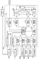
- FIG. 1 It is a figure which shows schematic the structure of the vehicle controlled by the vehicle running control device which concerns on an exemplary embodiment. It is a schematic diagram which shows the structure of an engine. It is a block diagram which shows the control system of an automobile. This is a configuration example of an arithmetic unit. It is a block diagram which shows the configuration example of a body system device control part and its surroundings.
- devices such as “traveling devices” and “body devices” refer to devices such as actuators and sensors mounted on a vehicle.
- FIG. 1 schematically shows a configuration of a vehicle 1 controlled by a vehicle travel control device 100 (hereinafter, referred to as a travel control device 100) according to the present embodiment.
- the vehicle 1 is a vehicle capable of manual driving that runs in response to an operation of the accelerator or the like by the driver, assisted driving that runs by assisting the driver's operation, and automatic driving that runs without the driver's operation. is there.
- the vehicle 1 includes an engine 10 as a drive source having a plurality of (four in this embodiment) cylinders 11, a transmission 20 connected to the engine 10, and a brake device 30 for braking the rotation of the front wheels 50 as drive wheels. And a steering device 40 for steering the front wheels 50 as steering wheels.
- the engine 10 is, for example, a gasoline engine. As shown in FIG. 2, each cylinder 11 of the engine 10 has an ignition plug 13 for igniting an injector 12 that supplies fuel into the cylinder 11 and an air-fuel mixture of the fuel and the intake air supplied into the cylinder 11. And are provided respectively. Further, the engine 10 is provided with an intake valve 14, an exhaust valve 15, and a valve operating mechanism 16 for adjusting the opening / closing operation of the intake valve 14 and the exhaust valve 15 for each cylinder 11. Further, the engine 10 is provided with a piston 17 that reciprocates in the cylinder 11 and a crankshaft 18 that is connected to the piston 17 via a connecting rod. The engine 10 may be a diesel engine. When the engine 10 is a diesel engine, the spark plug 13 may not be provided. The injector 12, the spark plug 13, and the valve operating mechanism 16 are examples of powertrain-related devices.
- the transmission 20 is, for example, a stepped automatic transmission.
- the transmission 20 is arranged on one side of the engine 10 in the cylinder row direction.
- the transmission 20 includes an input shaft (not shown) connected to the crankshaft 18 of the engine 10 and an output shaft (not shown) connected to the input shaft via a plurality of reduction gears (not shown). There is.
- the output shaft is connected to the axle 51 of the front wheel 50.
- the rotation of the crankshaft 18 is changed by the transmission 20 and transmitted to the front wheels 50.
- the transmission 20 is an example of a powertrain related device.
- the engine 10 and the transmission 20 are power train devices that generate a driving force for driving the vehicle 1.
- the operation of the engine 10 and the transmission 20 is controlled by the power train ECU (Electric Control Unit) 200.
- the power train ECU 200 uses fuel by the injector 12 based on a detection value of the accelerator opening sensor SW1 or the like that detects the accelerator opening corresponding to the operation amount of the accelerator pedal of the driver.
- the injection amount, fuel injection timing, ignition timing by the spark plug 13, and valve opening timing and valve opening period of the intake and exhaust valves 14 and 15 by the power valve mechanism 16 are controlled.
- the power train ECU 200 determines the transmission 20 based on the detection result of the shift sensor SW2 that detects the operation of the shift lever by the driver and the required driving force calculated from the accelerator opening. Adjust the gear stage. Further, when the vehicle 1 is assisted driving or automatic driving, the power train ECU 200 basically achieves the target driving force calculated by the arithmetic unit 110 described later, so that each traveling device (here, here,) is achieved. The control amount of the injector 12 and the like) is calculated, and the control signal is output to each traveling device.
- the powertrain ECU 200 is an example of a device control device.
- the brake device 30 includes a brake pedal 31, a brake actuator 33, a booster 34 connected to the brake actuator 33, a master cylinder 35 connected to the booster 34, and a DSC (Dynamic Stability Control) for adjusting the braking force. It has a device 36 and a brake pad 37 that actually brakes the rotation of the front wheel 50. A disc rotor 52 is provided on the axle 51 of the front wheel 50.
- the brake device 30 is an electric brake, and operates the brake actuator 33 according to the operation amount of the brake pedal 31 detected by the brake sensor SW3, and operates the brake pad 36 via the booster 34 and the master cylinder 35.
- the brake device 30 sandwiches the disc rotor 52 with the brake pads 37, and brakes the rotation of the front wheels 50 by the frictional force generated between the brake pads 37 and the disc rotor 52.
- the brake actuator 33 and the DSC device 36 are examples of brake-related devices.
- the operation of the brake device 30 is controlled by the brake microcomputer 300 and the DSC microcomputer 400.
- the brake microcomputer 300 controls the operation amount of the brake actuator 33 based on the detection value of the brake sensor SW3 or the like that detects the operation amount of the brake pedal 31 of the driver.
- the DSC microcomputer 400 operates and controls the DSC device 36 regardless of the operation of the driver's brake pedal 31, and applies braking force to the front wheels 50.
- the brake microcomputer 300 basically achieves the target braking force calculated by the arithmetic unit 110 described later, so that each traveling device (here, here,) is achieved.
- the control amount of the brake actuator 33) is calculated, and a control signal is output to each traveling device.
- the brake microcomputer 300 and the DSC microcomputer 400 are examples of device control devices.
- the brake microcomputer 300 and the DSC microcomputer 400 may be configured by one microcomputer.
- the steering device 40 includes a steering wheel 41 operated by the driver, an ENAS (Electronic Power Asist Steering) device 42 that assists the steering operation by the driver, and a pinion shaft 43 connected to the ENAS device 42.
- the ENAS device 42 includes an electric motor 42a and a speed reducing device 42b that reduces the driving force of the electric motor 42a and transmits it to the pinion shaft 43.
- the steering device 40 is a steer-by-wire type steering device, and operates the EPAS device 42 according to the operation amount of the steering wheel 41 detected by the steering angle sensor SW4 to rotate the pinion shaft 43 to operate the front wheels 50. To do.
- the pinion shaft 43 and the front wheel 50 are connected by a rack bar (not shown), and the rotation of the pinion shaft 43 is transmitted to the front wheels via the rack bar.
- the ENAS device 42 is an example of a steering-related device.
- the operation of the steering device 40 is controlled by the EPAS microcomputer 500.
- the EPAS microcomputer 500 controls the operation amount of the electric motor 42a based on the detection value of the steering angle sensor SW4 or the like.
- the ENAS microcomputer 500 basically achieves each traveling device (here, the target steering angle calculated by the arithmetic unit 110 described later) so as to achieve the target steering angle.
- the control amount of the EPAS device 42) is calculated, and a control signal is output to each traveling device.
- the ECAS microcomputer 500 is an example of a device control device.
- the power train ECU 200, the brake microcomputer 300, the DSC microcomputer 400, and the ENAS microcomputer 500 are configured to be able to communicate with each other.
- the powertrain ECU 200, the brake microcomputer 300, the DSC microcomputer 400, and the ENAS microcomputer 500 may be simply referred to as a device control device.
- the travel control device 100 calculates a route to be traveled by the vehicle 1 in order to enable assisted driving and automatic driving, and is a vehicle for following the route. It has an arithmetic unit 110 that determines the motion of 1.
- the arithmetic unit 110 is a microprocessor composed of one or a plurality of chips, and has a CPU, a memory, and the like. It should be noted that FIG. 3 shows a configuration for exerting the function (path generation function described later) according to the present embodiment, and does not show all the functions of the arithmetic unit 110.
- FIG. 4 is a configuration example of the arithmetic unit 110.
- the arithmetic unit 110 includes a processor 3 and a memory 4.
- the memory 4 stores a module that is software that can be executed by the processor 3.
- the functions of the respective parts shown in FIG. 3 are realized by the processor 3 executing each module stored in the memory 4.
- the memory 4 stores data representing a model used for processing by each part shown in FIG. There may be a plurality of processors 3 and memories 4.
- the arithmetic unit 110 determines the target motion of the vehicle 1 based on the outputs from a plurality of sensors and the like, and controls the operation of the device.
- Sensors and the like that output information to the arithmetic unit 110 are provided on the body and the like of the vehicle 1 and a plurality of cameras 70 for photographing the environment outside the vehicle, and a plurality of sensors and the like provided on the body of the vehicle 1 and detecting a target and the like outside the vehicle.
- the position sensor SW5 that detects the position (vehicle position information) of the vehicle 1 by using the radar 71 of the above and the Global Positioning System (GPS), and the vehicle such as the vehicle speed sensor, the acceleration sensor, and the yaw rate sensor.
- GPS Global Positioning System
- the arithmetic unit 110 is input with the communication information received by the external communication unit 72 from another vehicle located around the own vehicle and the traffic information from the navigation system.
- Each camera 70 is arranged so that the circumference of the vehicle 1 can be photographed 360 ° in the horizontal direction. Each camera 70 captures an optical image showing the environment outside the vehicle and generates image data. Each camera 70 outputs the generated image data to the arithmetic unit 110.
- the camera 70 is an example of an information acquisition means for acquiring information on the environment outside the vehicle.
- the image data acquired by each camera 70 is input to the HMI (Human Machine Interface) unit 700 in addition to the arithmetic unit 110.
- the HMI unit 700 displays information based on the acquired image data on a display device or the like in the vehicle.
- each radar 71 is arranged so that the detection range extends 360 ° horizontally around the vehicle 1.
- the type of radar 71 is not particularly limited, and for example, a millimeter wave radar or an infrared radar can be adopted.
- the radar 71 is an example of an information acquisition means for acquiring information on the environment outside the vehicle.
- the arithmetic unit 110 sets the travel path of the vehicle 1 during assisted driving or automatic driving, and sets the target motion of the vehicle 1 so that the vehicle 1 follows the traveling route.
- the computing device 110 responds to the vehicle exterior environment certification unit 111 that certifies the vehicle exterior environment based on the output from the camera 70 or the like and the vehicle exterior environment certified by the vehicle exterior environment certification unit 111.
- the candidate route generation unit 112 that calculates one or more candidate routes on which the vehicle 1 can travel, the vehicle behavior estimation unit 113 that estimates the behavior of the vehicle 1 based on the output from the vehicle state sensor SW6, and the vehicle behavior estimation unit 113.
- the occupant behavior estimation unit 114 that estimates the behavior of the occupant of the vehicle 1, the route determination unit 115 that determines the route that the vehicle 1 should travel, and the route determination unit 115 are set.
- the vehicle motion determination unit 116 that determines the target motion of the vehicle 1 for following the route, and the target physical quantity that the traveling device should generate in order to achieve the target motion determined by the vehicle motion determination unit 116 (for example, , Driving force, braking force, and steering angle), the driving force calculation unit 117, the braking force calculation unit 118, and the steering angle calculation unit 119.
- the candidate route calculation unit 112, the vehicle behavior estimation unit 113, the occupant behavior estimation unit 114, and the route determination unit 115 set the route for which the vehicle 1 should travel according to the external environment certified by the external environment certification unit 111. Make up the part.
- the arithmetic unit 110 recognizes an object outside the vehicle according to a predetermined rule, and generates a rule-based route generation unit 120 that generates a traveling route that avoids the object, and the vehicle 1 is placed on a road shoulder or the like. It has a backup unit 130 that generates a traveling route for guiding to a safe area.
- the arithmetic unit 110 includes a body device control unit 140 that controls a body-related device (appropriately referred to as a body device).
- the vehicle exterior environment certification unit 111 receives the output of the camera 70, radar 71, etc. mounted on the vehicle 1 and certifies the vehicle exterior environment.
- the certified out-of-vehicle environment includes at least roads and obstacles.
- the vehicle exterior environment certification unit 111 determines the vehicle environment including roads and obstacles by comparing the three-dimensional information around the vehicle 1 with the vehicle exterior environment model based on the data of the camera 70 and the radar 71. It shall be estimated.
- the vehicle exterior environment model is, for example, a trained model generated by deep learning, and can recognize roads, obstacles, and the like with respect to three-dimensional information around the vehicle.
- the vehicle exterior environment certification unit 111 identifies a free space, that is, an area where no object exists, by image processing from the image captured by the camera 70.
- image processing for example, a trained model generated by deep learning is used.
- a two-dimensional map representing the free space is generated.
- the vehicle exterior environment certification unit 111 acquires information on the target existing around the vehicle 1 from the output of the radar 71. This information is positioning information including the position and speed of the target.
- the vehicle exterior environment certification unit 111 combines the generated two-dimensional map with the positioning information of the target to generate a three-dimensional map representing the surroundings of the vehicle 1.
- the vehicle exterior environment certification unit 111 estimates the vehicle environment including roads and obstacles by comparing the generated three-dimensional map with the vehicle exterior environment model.
- a multi-layer neural network (DNN: Deep Neural Network) is used.
- DNN Deep Neural Network
- CNN Convolutional Neural Network
- the candidate route generation unit 112 generates a candidate route on which the vehicle 1 can travel based on the output of the vehicle exterior environment certification unit 111, the output of the position sensor SW5, the information transmitted from the vehicle exterior communication unit 73, and the like. For example, the candidate route generation unit 112 generates a travel route that avoids obstacles certified by the vehicle exterior environment certification unit 111 on the road certified by the vehicle exterior environment certification unit 111.
- the output of the vehicle exterior environment certification unit 111 includes, for example, travel path information regarding the travel path on which the vehicle 1 travels.
- the travel path information includes information on the shape of the travel path itself and information on an object on the travel path.
- Information on the shape of the road includes the shape of the road (straight line, curve, curve curvature), width of the road, number of lanes, width of each lane, and the like.
- the information about the object includes the relative position and speed of the object with respect to the vehicle, the attributes (type, moving direction) of the object, and the like. Examples of the types of objects include vehicles, pedestrians, roads, lane markings, and the like.
- the candidate route generation unit 112 calculates a plurality of candidate routes by using the state lattice method, and selects one or a plurality of candidate routes from among them based on the route cost of each candidate route. And.
- the route may be calculated by using another method.
- the candidate route generation unit 112 sets a virtual grid area on the travel path based on the travel route information.
- This grid area has a plurality of grid points.
- Each grid point identifies a position on the track.
- the candidate route generation unit 112 sets a predetermined grid point at the target arrival position.
- a plurality of candidate routes are calculated by a route search using a plurality of grid points in the grid area.
- the route branches from a certain grid point to an arbitrary grid point ahead in the traveling direction of the vehicle. Therefore, each candidate route is set to sequentially pass through a plurality of grid points.
- Each candidate route also includes time information indicating the time to pass each grid point, speed information related to speed / acceleration at each grid point, and other information related to vehicle motion.
- the candidate route generation unit 112 selects one or a plurality of travel routes from a plurality of candidate routes based on the route cost.
- the route cost here includes, for example, the degree of lane centering, the acceleration of the vehicle, the steering angle, the possibility of collision, and the like.
- the route determination unit 115 selects one travel route.
- the vehicle state estimation unit 113 measures the state of the vehicle from the outputs of sensors that detect the behavior of the vehicle, such as a vehicle speed sensor, an acceleration sensor, and a yaw rate sensor.
- the vehicle state estimation unit 113 uses a vehicle 6-axis model showing the behavior of the vehicle.
- the vehicle 6-axis model is a model of the acceleration in the three-axis directions of "front-back”, “left-right”, and “up-down” of the running vehicle, and the angular velocity in the three-axis directions of "pitch", "roll”, and “yaw”. It is a product. That is, instead of capturing the movement of the vehicle only on the classical vehicle motion engineering plane (only the front-back and left-right (XY movement) and yaw movement (Z-axis) of the vehicle), the suspension is applied to the four wheels.
- the vehicle state estimation unit 113 applies the vehicle 6-axis model to the travel route generated by the candidate route generation unit 112, and estimates the behavior of the vehicle 1 when following the travel route.
- the occupant behavior estimation unit 114 estimates the driver's health condition and emotions from the detection result of the occupant condition sensor SW7.
- the health condition includes, for example, health, mild fatigue, poor physical condition, and decreased consciousness.
- Emotions include, for example, fun, normal, boring, frustrated, and uncomfortable.
- the occupant state estimation unit 114 extracts the driver's face image from the image captured by the camera installed in the vehicle interior, and identifies the driver.
- the extracted face image and the identified driver information are given as inputs to the human model.
- the human model is, for example, a trained model generated by deep learning, and outputs the health state and emotions from the face image of each person who can be the driver of the vehicle 1.
- the occupant state estimation unit 114 outputs the driver's health state and emotions output by the human model.
- the occupant state estimation unit 114 uses the biometric information.
- the driver's biological information is measured from the output of the sensor.
- the human model inputs the biometric information of each person who can be the driver of the vehicle 1 and outputs the health state and emotions.
- the occupant state estimation unit 114 outputs the driver's health state and emotions output by the human model.
- a model for estimating the emotions that a human has with respect to the behavior of the vehicle 1 may be used for each person who can be the driver of the vehicle 1.
- the output of the vehicle behavior estimation unit 113, the driver's biological information, and the estimated emotional state may be managed in chronological order to build a model.
- this model for example, it is possible to predict the relationship between the driver's emotional increase (alertness) and the behavior of the vehicle.
- the occupant state estimation unit 114 may include a human body model as a human model.
- the human body model specifies, for example, the mass of the head (eg, 5 kg) and the muscle strength around the neck that supports the front, back, left, and right G.
- the human body model inputs the movement of the vehicle body (acceleration G or jerk), it outputs the expected physical and subjective occupants.
- the physical occupants are, for example, comfortable / moderate / unpleasant, and the subjective ones are, for example, unexpected / predictable.
- the human body model for example, the vehicle body behavior in which the head is slightly turned upside down is unpleasant for the occupant, so that the traveling route can be prevented from being selected.
- the vehicle body behavior in which the head moves forward as if bowing makes it easy for the occupant to take a posture against this and does not immediately lead to discomfort, so that the traveling route can be selected.
- the target movement can be dynamically determined so that the occupant's head does not shake or is lively.
- the occupant state estimation unit 114 applies a human model to the vehicle behavior estimated by the vehicle behavior estimation unit 113, and estimates changes in the health condition and emotions of the current driver with respect to the vehicle behavior.
- the route determination unit 115 determines the route on which the vehicle 1 should travel based on the output of the occupant state estimation unit 114. When the candidate route generation unit 112 has generated one route, the route determination unit 115 sets the route as the route on which the vehicle 1 should travel. When there are a plurality of routes generated by the candidate route generation unit 112, in consideration of the output of the occupant state estimation unit 114, for example, the route that the occupant (particularly the driver) feels most comfortable among the plurality of candidate routes, that is, Select a route that does not make the driver feel redundant, such as being too careful in avoiding obstacles.
- the rule-based route generation unit 120 Based on the output from the camera 70 and the radar 71, the rule-based route generation unit 120 recognizes an object outside the vehicle according to a predetermined rule without using deep learning, and travels so as to avoid the object. Generate a route. Similar to the candidate route generation unit 112, the rule-based route generation unit 120 also calculates a plurality of candidate routes using the state lattice method, and one or more of these based on the route cost of each candidate route. The candidate route of is selected. In the rule-based route generation unit 120, for example, the route cost is calculated based on the rule that the object does not enter within a few meters around the object. The rule-based route generation unit 120 may also calculate the route by using another method.
- the route information generated by the rule-based route generation unit 120 is input to the vehicle motion determination unit 116.
- the backup unit 130 Based on the outputs from the camera 70 and the radar 71, the backup unit 130 generates a traveling route for guiding the vehicle 1 to a safe area such as a road shoulder when the sensor or the like fails or the occupant is not in good physical condition. ..
- the backup unit 130 sets a safety area in which the vehicle 1 can be stopped urgently from the information of the position sensor SW5, and generates a traveling route until the vehicle 1 reaches the safety area.
- the backup unit 130 Similar to the candidate route generation unit 112, the backup unit 130 also calculates a plurality of candidate routes using the state lattice method, and one or a plurality of candidate routes from among these based on the route cost of each candidate route. Shall be selected.
- the backup unit 130 may also calculate the route by using another method.
- the route information generated by the backup unit 130 is input to the vehicle motion determination unit 116.
- the vehicle motion determination unit 116 determines the target motion for the travel route determined by the route determination unit 115.
- the target motion refers to steering and acceleration / deceleration that follow the traveling path. Further, the vehicle motion determination unit 116 calculates the movement of the vehicle body with respect to the traveling route selected by the route determination unit 115 with reference to the vehicle 6-axis model.
- the vehicle motion determination unit 116 determines the target motion for following the travel path generated by the rule-based route generation unit 120.
- the vehicle motion determination unit 116 determines the target motion for following the travel path generated by the backup unit 130.
- the vehicle motion determination unit 116 travels generated by the rule-based route generation unit 120.
- the route is selected as the route that the vehicle 1 should travel.
- the vehicle motion determination unit 116 uses the travel route generated by the backup unit 130 as the route that the vehicle 1 should travel. select.
- the physical quantity calculation unit includes a driving force calculation unit 117, a braking force calculation unit 118, and a steering angle calculation unit 119.
- the driving force calculation unit 117 calculates the target driving force to be generated by the power train device (engine 10 and transmission 20) in order to achieve the target motion.
- the braking force calculation unit 118 calculates the target braking force to be generated by the braking device 30 in order to achieve the target motion.
- the steering angle calculation unit 119 calculates a target steering angle to be generated by the steering device 40 in order to achieve the target motion.
- the arithmetic unit 110 has a function of controlling a body-related device (body-based device). That is, the body device control unit 140 sets the operation of the body device of the vehicle 1 such as a lamp and the door based on the output of the vehicle motion determination unit 116, and controls the body device according to the setting. To generate. The generated control signal is transmitted to each body device. As a result, the number of microcomputers that control each body device can be significantly reduced. In addition, communication between body devices can be speeded up.
- body-based device body-based device
- FIG. 5 is a block diagram showing a configuration example of the body device control unit 140 and its surroundings.
- the operation setting unit 141 sets, for example, the direction of the lamp when the vehicle 1 follows the travel path determined by the route determination unit 115.
- the lamps control unit 151 receives an instruction regarding the direction of the lamp from the operation setting unit 141, the lamp control unit 151 transmits a control signal for setting the direction to the lamp. Further, for example, when the operation setting unit 141 guides the vehicle 1 to the safety area set by the bup-up unit 130, after the vehicle reaches the safety area, the hazard lamp is turned on or the door is unlocked. Set the operation to do.
- the lamps control unit 151 When the lamps control unit 151 receives an instruction to turn on the hazard lamp from the operation setting unit 141, the lamp control unit 151 transmits a control signal to turn on the hazard lamp.
- the door control unit 152 receives an instruction to unlock the door from the operation setting unit 141, the door control unit 152 transmits a control signal for unlocking the door to the door.
- Other body devices include, for example, windows, horns, pretensioners and the like.
- a control device may be provided separately from the arithmetic unit 110.
- the airbag deployment microcomputer 600 is provided separately from the arithmetic unit 110 for the airbag.
- the airbag deployment microcomputer 600 is an example of a body device control device.
- the control function of the body device into the arithmetic unit 110, it is possible to accelerate the standby of the body device according to the prediction of the behavior of the vehicle. For example, when the possibility of a collision is predicted, the pretensioner can be operated weakly.
- a special harness is set for the hazard lamps in order to match the blinking timing of the hazard lamps placed on the front, rear, left and right and the door mirrors. Additional hardware was required, such as enabling current on / off with a single relay.
- the body device control unit 140 is responsible for supplying power to a plurality of hazard lamps, the blinking timing can be easily improved.
- the door lock is released by receiving the radio wave emitted by the owner's smart key approaching the parked vehicle, and the interior lamp is turned on as a welcome lamp to gradually increase the illumination, and the driver handles the door handle.
- hospitality control that continuously operates a series of body devices, such as displaying a brand icon on the display of the center console when the door is started to open by pulling.
- body microcomputers are distributed in each zone of the vehicle, in order to realize this control, the power is turned on in order in each zone of the vehicle, and the startup time is estimated so that each device operates continuously. It was necessary to perform complicated control to command each microcomputer via the in-vehicle network, such as wake-up in advance.
- the body device control unit 140 supervises and activates each device by turning on the power, hospitality control can be easily realized. Further, the specification change of the hospitality control can be easily realized by rewriting the program of the body device control unit 140.
- the calculation result of the arithmetic unit 110 is output to the power train ECU 200, the brake microcomputer 300, the ENAS microcomputer 500, and the body system microcomputer 700.
- information on the target driving force calculated by the driving force calculation unit 117 is input to the power train ECU 200, and information on the target braking force calculated by the braking force calculation unit 118 is input to the brake microcomputer 300.
- Information on the target steering angle calculated by the steering angle calculation unit 119 is input to the ENAS microcomputer 500.
- the arithmetic unit 100 sends a control signal generated by the body device control unit 140 to each body device such as a door or a lamp.
- the power train ECU 200 basically calculates the fuel injection timing of the injector 12 and the ignition timing of the spark plug 13 so as to achieve the target driving force, and sends control signals to these traveling devices. Is output.
- the brake microcomputer 300 basically calculates the control amount of the brake actuator 33 so as to achieve the target driving force, and outputs a control signal to the brake actuator 33.
- the ENAS microcomputer 500 basically calculates the amount of current supplied to the ENAS device 42 so as to achieve the target steering angle, and outputs a control signal to the ENAS device 42.
- the arithmetic unit 110 only calculates the target physical quantity to be output by each traveling device, and the control amount of each traveling device is calculated by each device control device 200 to 500. ..
- the amount of calculation of the arithmetic unit 110 can be reduced, and the calculation speed of the arithmetic unit 110 can be improved.
- the processing speed is high. As a result, the responsiveness of the traveling device to the environment outside the vehicle can be improved.
- the arithmetic unit 110 may calculate a rough physical quantity by causing each device control device 200 to 500 to calculate the control amount, the arithmetic speed is slower than that of each device control device 200 to 500. It will be good. As a result, the calculation accuracy of the arithmetic unit 110 can be improved.
- the arithmetic unit 110 and the device control devices 200 to 500 for operating and controlling the traveling device (injector 12, etc.) mounted on the vehicle 1 based on the arithmetic result of the arithmetic unit 110 are provided.
- the arithmetic unit 110 has an external environment certification unit 111 that certifies the external environment based on the outputs from the camera 70 and the radar 71 that acquire information on the external environment, and the external environment certification unit 111 that certifies the external environment.
- a route setting unit (route calculation unit 112, etc.) that sets a route on which the vehicle 1 should travel, a vehicle motion determination unit 116 that determines a target motion of the vehicle 1 for following the route set by the route setting unit, and a vehicle.
- the arithmetic unit 110 includes a body device control unit 140 that sets the operation of the body device of the vehicle based on the output of the motion determination unit 116 and generates a control signal for controlling the body device.
- the arithmetic unit 110 includes a body device control unit 140 that controls the body device of the vehicle, in addition to the function of executing the calculation for operating the traveling device mounted on the vehicle.
- the control function of the body device is incorporated into the arithmetic unit 110, so that the number of microcomputers that control the body device can be significantly reduced.
- communication between body devices can be speeded up. Further, in the body device, the standby can be accelerated according to the behavior prediction of the vehicle.
- the vehicle travel control device 100 includes device control devices 200 to 500 for operating and controlling the travel device in addition to the arithmetic unit 110, the control function of the travel device is not incorporated in the arithmetic unit 110. It is possible to suppress an increase in the arithmetic load of the arithmetic unit 110.
- the arithmetic unit 110 includes physical quantity calculation units 117 to 119 for calculating a target physical quantity to be generated by the traveling device in order to achieve the target motion determined by the vehicle motion determination unit 116, and is a device control device.
- the 200 to 500 calculate the control amount of the traveling device so as to achieve the target physical quantity calculated by the physical quantity calculation units 117 to 119, and output a control signal to the traveling device.
- the arithmetic unit 110 only calculates the physical quantity to be achieved, and the device control devices 200 to 500 calculate the actual control amount of the traveling device.
- the amount of calculation of the arithmetic unit 110 can be reduced, and the calculation speed of the arithmetic unit 110 can be improved.
- the processing speed is high. As a result, the responsiveness of the traveling device to the environment outside the vehicle can be improved.
- the vehicle exterior environment certification unit 111 certifies the vehicle exterior environment using deep learning, and the arithmetic unit 110 has a particularly large amount of calculation. Therefore, if the control amount of the traveling device is calculated by the device control devices 200 to 500 other than the arithmetic unit 110, the effect of further improving the responsiveness of the traveling device to the outside environment is more appropriately exhibited. can do.
- the driving force calculation unit 117, the braking force calculation unit 118, and the steering angle calculation unit 119 may change the target driving force or the like according to the state of the driver of the vehicle 1 during the assist driving of the vehicle 1. For example, when the driver is enjoying driving (the driver's emotions are "fun"), the target driving force or the like may be reduced to make the driving as close to manual driving as possible. On the other hand, when the driver is in a state of poor physical condition, the target driving force or the like may be increased so as to approach automatic driving as much as possible.
- the route determination unit 115 determines the route on which the vehicle 1 should travel.
- the route determination unit 115 may be omitted, and the vehicle motion determination unit 116 may determine the route on which the vehicle 1 should travel. That is, the vehicle motion determination unit 116 may concurrently serve as a part of the route setting unit and the target motion determination unit.
- the driving force calculation unit 117, the braking force calculation unit 118, and the steering angle calculation unit 119 have calculated the target physical quantity such as the target driving force.
- the vehicle motion determination unit 116 may calculate the target physical quantity by omitting the driving force calculation unit 117, the braking force calculation unit 118, and the steering angle calculation unit 119. That is, the vehicle motion determination unit 116 may concurrently serve as the target motion determination unit and the physical quantity calculation unit.
- the technology disclosed here is useful as a vehicle travel control device that controls the travel of the vehicle.
Abstract
車両走行制御装置(100)は、演算装置(110)と、車両に搭載された走行用デバイスを作動制御するデバイス制御装置(200,300,400,500)とを備える。演算装置(110)は、車外環境を認定する車外環境認定部(111)と、車両が走行すべき経路を設定する経路設定部(112,113,114,115)と、設定した経路を追従するための車両の目標運動を決定する車両運動決定部(116)と、車両運動決定部(116)の出力に基づいて、車両のボディ系デバイスの動作を設定し、ボディ系デバイスを制御する制御信号を生成するボディ系デバイス制御部(140)とを備える。
Description
ここに開示された技術は、車両走行制御装置に関する技術分野に属する。
従来より、車両に搭載された複数の走行用の車載機器を制御する車両走行制御装置が知られている。
例えば、特許文献1には、車両走行制御装置として、複数の車載機器の機能に応じて予め複数のドメインに区分けされ、その複数のドメインにおいて、それぞれ、車載機器を制御するための機器制御部と、機器制御部を統括するドメイン制御部とに階層化され、各ドメイン制御部の上位に位置づけられ、各ドメイン制御部を統括する統合制御部とを備える制御システムが開示されている。
また、特許文献1では、機器制御部は、対応する車載機器の制御量を算出して、該制御量を達成するための制御信号を各車載機器に出力している。
ところで、昨今では、国家的に自動運転システムの開発が推進されている。自動運転システムでは、一般に、カメラ等により車外環境情報が取得され、取得された車外環境情報に基づいて車両が走行すべき経路が算出される。また、自動運転システムでは、走行すべき経路を追従するために走行用デバイスが制御される。
また、最近の車両では、ドアやライトのようなボディ関係のデバイスを制御するマイコンの個数が増大している。車両一台あたりのマイコン数は、多い車種では数百にも上っている。ところが、自動運転システムにおける演算装置とボディ関係のデバイスを制御する多数のマイコンとを別々に設けると、構成が複雑になりコストが増大することになり、好ましくない。
ここに開示された技術は、斯かる点に鑑みてなされたものであり、その目的とするとこは、演算装置が算出した経路を追従するように走行用デバイスを作動制御する車両走行制御装置において、簡易な構成により、ボディ関係のデバイスを制御可能にすることにある。
自動運転システムにおいて、アクチュエータやセンサ等のデバイスが多数増設されると、車内通信の構成がソフトウェアおよびハードウェアの両方の面で極度に複雑化する。このような構成の複雑化を解消するためには、例えば、デバイスが個別に有する制御機能を中央演算装置に取り込み、中央演算装置が車内通信ネットワークを介してデバイスを直接制御する形態のシステム構成が考えられる。
その一方で、中央演算装置にデバイス制御機能を取り込む場合、演算負荷が増すことによって本来の自動運転用演算の演算速度を損なうことは回避したい。そこで、本開示では、中央演算装置の演算負荷がいたずらに増大しないように、走行用デバイスの制御とボディ系デバイスの制御とを区別して、中央演算装置にボディ系デバイスの制御機能を取り込むようにする。
前記課題を解決するために、ここに開示された技術では、車両の走行を制御する車両走行制御装置は、演算装置と、前記演算装置の演算結果に基づいて、前記車両に搭載された走行用デバイスを作動制御するデバイス制御装置とを備え、前記演算装置は、車外環境の情報を取得する情報取得手段からの出力を基にして車外環境を認定する車外環境認定部と、前記車外環境認定部が認定した車外環境に応じて、前記車両が走行すべき経路を設定する経路設定部と、前記経路設定部が設定した経路を追従するための前記車両の目標運動を決定する目標運動決定部と、前記目標運動決定部の出力に基づいて、前記車両のボディ系デバイスの動作を設定し、前記ボディ系デバイスを制御する制御信号を生成するボディ系デバイス制御部と、を有する。
この構成によると、演算装置は、車両に搭載された走行用デバイスを作動させるための演算を実行する機能の他に、車両のボディ系デバイスを制御するボディ系デバイス制御部を備える。これにより、演算装置にボディ系デバイスの制御機能が取り込まれるので、ボディ系デバイスを制御するマイコンを大幅に削減することができる。また、ボディ系デバイス同士の間の通信を高速化することができる。さらに、ボディ系デバイスにおいて、車両の挙動予測に応じたスタンバイを早期化させることができる。また、車両走行制御装置は、演算装置とは別に、走行用デバイスを作動制御するデバイス制御装置を備えており、走行用デバイスの制御機能は演算装置に組み込まれないので、演算装置の演算負荷の増大を抑制することができる。
前記車両走行制御装置において、前記ボディ系デバイスは、ランプ、ドアのうち少なくともいずれかを含む、としてもよい。
前記車両走行制御装置において、前記演算装置と別個に構成されており、前記演算装置からの指示を受けて、前記ボディ系デバイスの1つである第1デバイスを制御する制御信号を生成するボディ系デバイス制御装置を備える、としてもよい。
この構成によると、制御機能を演算装置に組み込むことが困難なボディ系デバイスに関しては、演算装置と別個に、ボディ系デバイス制御装置を備えることができる。
前記車両走行制御装置における演算装置において、前記車外環境認定部は深層学習を利用して車外環境を認定する、という構成でもよい。
この構成によると、車外環境認定部は深層学習を利用して車外環境を認識するため、演算装置は特に計算量が多くなる。このため、走行用デバイスの制御量を、演算装置以外のデバイス制御装置により算出するようにすれば、車外環境に対する走行用デバイスの応答性をより向上させるという効果をより適切に発揮することができる。
以上説明したように、ここに開示された技術によると、演算装置が算出した経路を追従するように走行用デバイスを作動制御する車両走行制御装置において、簡易な構成によって、ボディ関係のデバイスを制御可能にすることができる。
以下、例示的な実施形態について、図面を参照しながら詳細に説明する。なお、本開示における「走行用デバイス」「ボディ系デバイス」等の「デバイス」は、車両に搭載されるアクチュエータやセンサ等の装置類のことを示す。
図1は、本実施形態に係る車両走行制御装置100(以下、走行制御装置100という)により制御される車両1の構成を概略的に示す。車両1は、運転者によるアクセル等の操作に応じて走行するマニュアル運転と、運転者の操作をアシストして走行するアシスト運転と、運転者の操作なしに走行する自動運転とが可能な自動車である。
車両1は、複数(本実施形態では4つ)の気筒11を有する駆動源としてのエンジン10と、エンジン10に連結されたトランスミッション20と、駆動輪としての前輪50の回転を制動するブレーキ装置30と、操舵輪としての前輪50を操舵するステアリング装置40とを有する。
エンジン10は、例えば、ガソリンエンジンである。エンジン10の各気筒11には、図2に示すように、気筒11内に燃料を供給するインジェクタ12と、燃料と気筒11内に供給された吸気との混合気を着火させるための点火プラグ13とがそれぞれ設けられている。また、エンジン10は、気筒11毎に、吸気弁14と、排気弁15と、吸気弁14及び排気弁15の開閉動作を調整する動弁機構16とが設けられている。また、エンジン10には、気筒11内を往復動するピストン17と、該ピストン17とコネクティングロッドを介して連結されたクランクシャフト18とが設けられている。尚、エンジン10は、ディーゼルエンジンであってもよい。エンジン10がディーゼルエンジンである場合には、点火プラグ13は設けなくてもよい。インジェクタ12、点火プラグ13、及び動弁機構16は、パワートレイン関連デバイスの一例である。
トランスミッション20は、例えば、有段式の自動変速機である。トランスミッション20は、エンジン10の気筒列方向における一側に配置されている。トランスミッション20は、エンジン10のクランクシャフト18と連結されたインプットシャフト(図示省略)と、該インプットシャフトと複数の減速ギヤ(図示省略)を介して連結されたアウトプットシャフト(図示省略)とを備えている。前記アウトプットシャフトは、前輪50の車軸51と連結されている。クランクシャフト18の回転は、トランスミッション20により変速されて、前輪50に伝達される。トランスミッション20はパワートレイン関連デバイスの一例である。
エンジン10とトランスミッション20とは、車両1を走行させるための駆動力を生成するパワートレイン装置である。エンジン10及びトランスミッション20は、パワートレインECU(Electric Control Unit)200により作動制御される。例えば、車両1がマニュアル運転であるときには、パワートレインECU200は、運転者のアクセルペダルの操作量に対応したアクセル開度を検出するアクセル開度センサSW1等の検出値に基づいて、インジェクタ12による燃料噴射量や燃料噴射タイミング、点火プラグ13による点火タイミング、及び動弁機構16による吸排気弁14,15の開弁タイミング及び開弁期間等を制御する。また、車両1がマニュアル運転であるときには、パワートレインECU200は、運転者によるシフトレバーの操作を検出するシフトセンサSW2の検出結果やアクセル開度から算出される要求駆動力に基づいて、トランスミッション20のギヤ段を調整する。また、車両1がアシスト運転や自動運転であるときには、パワートレインECU200は、基本的には、後述する演算装置110により算出される目標駆動力を達成するように、各走行用デバイス(ここでは、インジェクタ12等)の制御量を算出して、各走行用デバイスに制御信号を出力する。パワートレインECU200は、デバイス制御装置の一例である。
ブレーキ装置30は、ブレーキペダル31と、ブレーキアクチュエータ33と、ブレーキアクチュエータ33と接続されたブースタ34と、ブースタ34と接続されたマスタシリンダ35と、制動力を調整するためのDSC(Dynamic Stability Control)装置36と、実際に前輪50の回転を制動するブレーキパッド37とを有する。前輪50の車軸51には、ディスクロータ52が設けられている。ブレーキ装置30は、電動ブレーキであって、ブレーキセンサSW3が検知したブレーキペダル31の操作量に応じてブレーキアクチュエータ33を作動させて、ブースタ34及びマスタシリンダ35を介してブレーキパッド36を作動させる。ブレーキ装置30は、ブレーキパッド37によりディスクロータ52を挟んで、ブレーキパッド37とディスクロータ52との間に生じる摩擦力により、前輪50の回転を制動する。ブレーキアクチュエータ33及びDSC装置36は、ブレーキ関連デバイスの一例である。
ブレーキ装置30は、ブレーキマイコン300及びDSCマイコン400により作動制御される。例えば、車両1がマニュアル運転であるときには、ブレーキマイコン300は、運転者のブレーキペダル31の操作量を検出するブレーキセンサSW3等の検出値に基づいて、ブレーキアクチュエータ33の操作量を制御する。また、DSCマイコン400は、運転者のブレーキペダル31の操作に関わらずにDSC装置36を作動制御して、前輪50に制動力を付与する。また、車両1がアシスト運転や自動運転であるときには、ブレーキマイコン300は、基本的には、後述する演算装置110により算出される目標制動力を達成するように、各走行用デバイス(ここでは、ブレーキアクチュエータ33)の制御量を算出して、各走行用デバイスに制御信号を出力する。ブレーキマイコン300及びDSCマイコン400は、デバイス制御装置の一例である。なお、ブレーキマイコン300とDSCマイコン400とを1つのマイコンで構成してもよい。
ステアリング装置40は、運転者により操作されるステアリングホイール41と、運転者によるステアリング操作をアシストするEPAS(Electronic Power Asist Steering)装置42と、EPAS装置42に連結されたピニオンシャフト43とを有する。EPAS装置42は、電動モータ42aと、電動モータ42aの駆動力を減速してピニオンシャフト43に伝達する減速装置42bとを有する。ステアリング装置40は、ステアバイワイヤ方式のステアリング装置であって、操舵角センサSW4が検知したステアリングホイール41の操作量に応じてEPAS装置42を作動させて、ピニオンシャフト43を回転させて前輪50を操作する。ピニオンシャフト43と前輪50とは不図示のラックバーにより連結されており、ピニオンシャフト43の回転は、該ラックバーを介して前輪に伝達される。EPAS装置42は、ステアリング関連デバイスの一例である。
ステアリング装置40は、EPASマイコン500により作動制御される。例えば、車両1がマニュアル運転であるときには、EPASマイコン500は、操舵角センサSW4等の検出値に基づいて、電動モータ42aの操作量を制御する。また、車両1がアシスト運転や自動運転であるときには、EPASマイコン500は、基本的には、後述する演算装置110により算出される目標操舵角を達成するように、各走行用デバイス(ここでは、EPAS装置42)の制御量を算出して、各走行用デバイスに制御信号を出力する。EPASマイコン500は、デバイス制御装置の一例である。
詳しくは後述するが、本実施形態では、パワートレインECU200、ブレーキマイコン300、DSCマイコン400、及びEPASマイコン500は、互いに通信可能に構成されている。以下の説明において、パワートレインECU200、ブレーキマイコン300、DSCマイコン400、及びEPASマイコン500を単にデバイス制御装置ということがある。
本実施形態において、図3に示すように、走行制御装置100は、アシスト運転及び自動運転を可能にするために、車両1が走行すべき経路を算出するとともに、該経路を追従するための車両1の運動を決定する演算装置110を有する。演算装置110は、1つ又は複数のチップで構成されたマイクロプロセッサであって、CPUやメモリ等を有している。尚、図3においては、本実施形態に係る機能(後述する経路生成機能)を発揮するための構成を示しており、演算装置110が有する全ての機能を示しているわけではない。
図4は演算装置110の構成例である。図4の構成例では、演算装置110は、プロセッサ3と、メモリ4とを備える。メモリ4は、プロセッサ3によって実行可能なソフトウェアであるモジュールを格納している。図3に示す各部の機能は、プロセッサ3が、メモリ4に格納された各モジュールを実行することによって、実現される。また、メモリ4は、図3に示す各部が処理に用いるモデルを表すデータを格納している。なお、プロセッサ3およびメモリ4は、複数個あってもかまわない。
図3に示すように、演算装置110は、複数のセンサ等からの出力に基づいて、車両1の目標運動を決定して、デバイスの作動制御を行う。演算装置110に情報を出力するセンサ等は、車両1のボディ等に設けられかつ車外環境を撮影する複数のカメラ70と、車両1のボディ等に設けられかつ車外の物標等を検知する複数のレーダ71と、全地球測位システム(Global Positioning System:GPS)を利用して、車両1の位置(車両位置情報)を検出する位置センサSW5と、車速センサ、加速度センサ、ヨーレートセンサ等の車両の挙動を検出するセンサ類の出力から構成され車両1の状態を取得する車両状態センサSW6と、車内カメラ等により構成され、車両1の乗員の状態を取得する乗員状態センサSW7とを含む。また、演算装置110には、車外通信部72が受信した、自車両の周囲に位置する他車両からの通信情報やナビゲーションシステムからの交通情報が入力される。
各カメラ70は、車両1の周囲を水平方向に360°撮影できるようにそれぞれ配置されている。各カメラ70は、車外環境を示す光学画像を撮像して画像データを生成する。各カメラ70は、生成した画像データを演算装置110に出力する。カメラ70は、車外環境の情報を取得する情報取得手段の一例である。
各カメラ70が取得した画像データは、演算装置110以外にも、HMI(Human Machine Interface)ユニット700に入力される。HMIユニット700は、取得した画像データに基づく情報を車内のディスプレイ装置等に表示する。
各レーダ71は、カメラ70と同様に、検出範囲が車両1の周囲を水平方向に360°広がるようにそれぞれ配置されている。レーダ71の種類は特に限定されず、例えば、ミリ波レーダや赤外線レーダを採用することができる。レーダ71は、車外環境の情報を取得する情報取得手段の一例である。
演算装置110は、アシスト運転時や自動運転時には、車両1の走行経路を設定して、車両1が該走行経路を追従するように、車両1の目標運動を設定する。演算装置110は、車両1の目標運動を設定するために、カメラ70等からの出力を基にして車外環境を認定する車外環境認定部111と、車外環境認定部111が認定した車外環境に応じて、車両1が走行可能な1つ又は複数の候補経路を算出する候補経路生成部112と、車両状態センサSW6からの出力を基にして車両1の挙動を推定する車両挙動推定部113と、乗員状態センサSW7からの出力を基にして、車両1の乗員の挙動を推定する乗員挙動推定部114と、車両1が走行すべき経路を決定する経路決定部115と、経路決定部115が設定した経路を追従するための車両1の目標運動を決定する車両運動決定部116と、車両運動決定部116が決定した目標運動を達成するために、前記走行用デバイスが生成すべき目標物理量(例えば、駆動力、制動力、及び操舵角)を算出する、駆動力算出部117、制動力算出部118、及び操舵角算出部119を有する。候補経路算出部112、車両挙動推定部113、乗員挙動推定部114及び経路決定部115は、車外環境認定部111が認定した車外環境に応じて、車両1が走行すべき経路を設定する経路設定部を構成する。
また、演算装置110は、セーフティ機能として、所定のルールにより車外の対象物を認定して、該対象物を避けるような走行経路を生成するルールベース経路生成部120と、車両1を路肩等の安全領域に誘導するための走行経路を生成するバックアップ部130とを有する。
さらに、演算装置110は、ボディ関係のデバイス(適宜、ボディ系デバイスと称する)を制御するボディ系デバイス制御部140を備える。
〈車外環境認定部〉
車外環境認定部111は、車両1に搭載されたカメラ70やレーダ71等の出力を受け、車外環境を認定する。認定する車外環境は、少なくとも道路および障害物を含む。ここでは、車外環境認定部111は、カメラ70やレーダ71のデータを基にして、車両1の周囲の3次元情報と車外環境モデルとを対照することにより、道路および障害物を含む車両環境を推定するものとする。車外環境モデルは、例えば深層学習によって生成された学習済みモデルであって、車両周囲の3次元情報に対して、道路や障害物等を認識することができる。
車外環境認定部111は、車両1に搭載されたカメラ70やレーダ71等の出力を受け、車外環境を認定する。認定する車外環境は、少なくとも道路および障害物を含む。ここでは、車外環境認定部111は、カメラ70やレーダ71のデータを基にして、車両1の周囲の3次元情報と車外環境モデルとを対照することにより、道路および障害物を含む車両環境を推定するものとする。車外環境モデルは、例えば深層学習によって生成された学習済みモデルであって、車両周囲の3次元情報に対して、道路や障害物等を認識することができる。
例えば、車外環境認定部111は、カメラ70が撮像した画像から、画像処理によって、フリースペースすなわち物体が存在しない領域を特定する。ここでの画像処理には、例えば深層学習によって生成された学習済みモデルが利用される。そしてフリースペースを表す2次元のマップを生成する。また、車外環境認定部111は、レーダ71の出力から、車両1の周辺に存在する物標の情報を取得する。この情報は、物標の位置や速度等を含む測位情報である。そして、車外環境認定部111は、生成された2次元のマップと物標の測位情報とを結合させて、車両1の周囲を表す3次元マップを生成する。ここでは、カメラ70の設置位置および撮像方向の情報、レーダ71の設置位置および送信方向の情報が用いられる。車外環境認定部111は、生成した3次元マップと車外環境モデルとを対比することによって、道路及び障害物を含む車両環境を推定する。尚、深層学習では、多層ニューラルネットワーク(DNN:Deep Neural Network)が用いられる。多層ニューラルネットワークとして、例えば、CNN(Convolutional Neural Network)がある。
〈候補経路生成部〉
候補経路生成部112は、車外環境認定部111の出力、位置センサSW5の出力、及び車外通信部73から送信される情報等を基にして、車両1が走行可能な候補経路を生成する。例えば、候補経路生成部112は、車外環境認定部111によって認定された道路上において、車外環境認定部111によって認定された障害物を回避する走行経路を生成する。車外環境認定部111の出力は、例えば、車両1が走行する走行路に関する走行路情報が含まれている。走行路情報には、走行路自体の形状に関する情報や、走行路上の対象物に関する情報が含まれる。走行路形状に関する情報には、走行路の形状(直線、カーブ、カーブ曲率)、走行路幅、車線数、各車線幅等が含まれる。対象物に関する情報には、車両に対する対象物の相対位置及び相対速度、対象物の属性(種類、移動方向)等が含まれる。対象物の種類としては、例えば、車両、歩行者、道路、区画線等がある。
候補経路生成部112は、車外環境認定部111の出力、位置センサSW5の出力、及び車外通信部73から送信される情報等を基にして、車両1が走行可能な候補経路を生成する。例えば、候補経路生成部112は、車外環境認定部111によって認定された道路上において、車外環境認定部111によって認定された障害物を回避する走行経路を生成する。車外環境認定部111の出力は、例えば、車両1が走行する走行路に関する走行路情報が含まれている。走行路情報には、走行路自体の形状に関する情報や、走行路上の対象物に関する情報が含まれる。走行路形状に関する情報には、走行路の形状(直線、カーブ、カーブ曲率)、走行路幅、車線数、各車線幅等が含まれる。対象物に関する情報には、車両に対する対象物の相対位置及び相対速度、対象物の属性(種類、移動方向)等が含まれる。対象物の種類としては、例えば、車両、歩行者、道路、区画線等がある。
ここでは、候補経路生成部112は、ステートラティス法を用いて複数の候補経路を計算し、これらの中からそれぞれの候補経路の経路コストに基づいて、1つまたは複数の候補経路を選択するものとする。ただし、他の手法を用いて経路の算出を行ってもよい。
候補経路生成部112は、走行路情報に基づいて走行路上に仮想のグリッド領域を設定する。このグリッド領域は、複数のグリッド点を有する。各グリッド点により、走行路上の位置が特定される。候補経路生成部112は、所定のグリッド点を目標到達位置に設定する。そして、グリッド領域内の複数のグリッド点を用いた経路探索により複数の候補経路を演算する。ステートラティス法では、あるグリッド点から車両の進行方向前方の任意のグリッド点へ経路が枝分かれしていく。したがって、各候補経路は、複数のグリッド点を順次に通過するように設定される。各候補経路は、各グリッド点を通過する時間を表す時間情報、各グリッド点での速度・加速度等に関する速度情報、その他車両運動に関する情報等も含む。
候補経路生成部112は、複数の候補経路から、経路コストに基づいて1つまたは複数の走行経路を選択する。ここでの経路コストは、例えば、レーンセンタリングの程度、車両の加速度、ステアリング角度、衝突の可能性等がある。なお、候補経路生成部112が複数の走行経路を選択する場合は、経路決定部115が、1つの走行経路を選択する。
〈車両挙動推定部〉
車両状態推定部113は、車速センサ、加速度センサ、ヨーレートセンサ等の車両の挙動を検出するセンサ類の出力から、車両の状態を計測する。車両状態推定部113は、車両の挙動を示す車両6軸モデルを用いる。
車両状態推定部113は、車速センサ、加速度センサ、ヨーレートセンサ等の車両の挙動を検出するセンサ類の出力から、車両の状態を計測する。車両状態推定部113は、車両の挙動を示す車両6軸モデルを用いる。
ここで、車両6軸モデルとは、走行中の車両の「前後」「左右」「上下」の3軸方向の加速度と、「ピッチ」「ロール」「ヨー」の3軸方向の角速度を、モデル化したものである。すなわち、車両の動きを古典的な車両運動工学的な平面上のみ(車両の前後左右(X-Y移動)とヨー運動(Z軸)のみ)で捉えるのではなく、4つの車輪にサスペンションを介して乗っている車体のピッチング(Y軸)およびロール(X軸)運動とZ軸の移動(車体の上下動)の、計6軸を用いて車両の挙動を再現する数値モデルである。
車両状態推定部113は、候補経路生成部112が生成した走行経路に対して、車両6軸モデルを当てはめて、該走行経路を追従する際の車両1の挙動を推定する。
〈乗員挙動推定部〉
乗員挙動推定部114は、乗員状態センサSW7の検出結果から、特に、運転者の健康状態や感情を推定する。健康状態としては、例えば、健康、軽い疲労、体調不良、意識低下等がある。感情としては、例えば、楽しい、普通、退屈、イライラ、不快等がある。
乗員挙動推定部114は、乗員状態センサSW7の検出結果から、特に、運転者の健康状態や感情を推定する。健康状態としては、例えば、健康、軽い疲労、体調不良、意識低下等がある。感情としては、例えば、楽しい、普通、退屈、イライラ、不快等がある。
例えば、乗員状態推定部114は、例えば、車室内に設置されたカメラによって撮像された画像から、運転者の顔画像を抽出し、運転者を特定する。抽出した顔画像と特定した運転者の情報は、人間モデルに入力として与えられる。人間モデルは、例えば深層学習によって生成された学習済みモデルであり、当該車両1の運転者であり得る各人について、その顔画像から、健康状態および感情を出力する。乗員状態推定部114は、人間モデルが出力した運転者の健康状態および感情を、出力する。
また、運転者の情報を取得するための乗員状態センサSW7として、皮膚温センサ、心拍センサ、血流量センサ、発汗センサ等の生体情報センサが用いられる場合は、乗員状態推定部114は、生体情報センサの出力から、運転者の生体情報を計測する。この場合、人間モデルは、当該車両1の運転者であり得る各人について、その生体情報を入力とし、健康状態および感情を出力する。乗員状態推定部114は、人間モデルが出力したドライバの健康状態および感情を、出力する。
また、人間モデルとして、当該車両1の運転者であり得る各人について、車両1の挙動に対して人間が持つ感情を推定するモデルを用いてもよい。この場合には、車両挙動推定部113の出力、運転者の生体情報、推定した感情状態を時系列で管理して、モデルを構築すればよい。このモデルによって、例えば、ドライバの感情の高まり(覚醒度)と車両の挙動との関係を予測することが可能となる。
また、乗員状態推定部114は、人間モデルとして、人体モデルを備えていてもよい。人体モデルは、例えば、頭部質量(例:5kg)と前後左右Gを支える首周り筋力等を特定している。人体モデルは、車体の動き(加速度Gや加加速度)を入力すると、予想される乗員のフィジカルと主観を出力する。乗員のフィジカルとしては例えば、心地よい/適度/不快、主観としては例えば、不意/予測可能、等である。人体モデルを参照することによって、例えば、頭部がわずかでも仰け反らせるような車体挙動は乗員にとって不快であるので、その走行経路を選択しないようにすることができる。一方、頭部がお辞儀するように前に移動する車体挙動は乗員がこれに抗する姿勢をとりやすく、直ちに不快につながらないようので、その走行経路を選択するようにすることができる。あるいは、人体モデルを参照することによって、例えば、乗員の頭部が揺れないように、あるいは、生き生きするようにダイナミックに、目標運動を決定することができる。
乗員状態推定部114は、車両挙動推定部113により推定された車両挙動に対して、人間モデルを当てはめて、現在の運転者の、車両挙動に対する健康状態の変化や感情の変化を推定する。
〈経路決定部〉
経路決定部115は、乗員状態推定部114の出力に基づいて、車両1が走行すべき経路を決定する。候補経路生成部112が生成した経路が1つである場合には、経路決定部115は当該経路を車両1が走行すべき経路とする。候補経路生成部112が生成した経路が複数ある場合には、乗員状態推定部114の出力を考慮して、例えば、複数の候補経路のうち乗員(特に運転者)が最も快適と感じる経路、すなわち、障害物を回避するに当たって慎重過ぎるなどの冗長さを運転者に感じさせない経路を選択する。
経路決定部115は、乗員状態推定部114の出力に基づいて、車両1が走行すべき経路を決定する。候補経路生成部112が生成した経路が1つである場合には、経路決定部115は当該経路を車両1が走行すべき経路とする。候補経路生成部112が生成した経路が複数ある場合には、乗員状態推定部114の出力を考慮して、例えば、複数の候補経路のうち乗員(特に運転者)が最も快適と感じる経路、すなわち、障害物を回避するに当たって慎重過ぎるなどの冗長さを運転者に感じさせない経路を選択する。
〈ルールベース経路生成部〉
ルールベース経路生成部120は、カメラ70及びレーダ71からの出力を基にして、深層学習を利用せずに、所定のルールにより車外の対象物を認定して、該対象物を避けるような走行経路を生成する。ルールベース経路生成部120でも、候補経路生成部112と同様に、ステートラティス法を用いて複数の候補経路を計算し、これらの中からそれぞれの候補経路の経路コストに基づいて、1つまたは複数の候補経路を選択するものとする。ルールベース経路生成部120では、例えば、対象物の周囲数m以内には侵入しないというルールに基づいて、経路コストが算出される。このルールベース経路生成部120でも、他の手法を用いて経路の算出を行ってもよい。
ルールベース経路生成部120は、カメラ70及びレーダ71からの出力を基にして、深層学習を利用せずに、所定のルールにより車外の対象物を認定して、該対象物を避けるような走行経路を生成する。ルールベース経路生成部120でも、候補経路生成部112と同様に、ステートラティス法を用いて複数の候補経路を計算し、これらの中からそれぞれの候補経路の経路コストに基づいて、1つまたは複数の候補経路を選択するものとする。ルールベース経路生成部120では、例えば、対象物の周囲数m以内には侵入しないというルールに基づいて、経路コストが算出される。このルールベース経路生成部120でも、他の手法を用いて経路の算出を行ってもよい。
ルールベース経路生成部120が生成した経路の情報は車両運動決定部116に入力される。
〈バックアップ部〉
バックアップ部130は、カメラ70及びレーダ71からの出力を基にして、センサ等の故障時や乗員の体調が優れない時に、車両1を路肩等の安全領域に誘導するための走行経路を生成する。バックアップ部130は、例えば、位置センサSW5の情報から車両1を緊急停止させることができる安全領域を設定し、該安全領域に到達するまでの走行経路を生成する。バックアップ部130でも、候補経路生成部112と同様に、ステートラティス法を用いて複数の候補経路を計算し、これらの中からそれぞれの候補経路の経路コストに基づいて、1つまたは複数の候補経路を選択するものとする。このバックアップ部130でも、他の手法を用いて経路の算出を行ってもよい。
バックアップ部130は、カメラ70及びレーダ71からの出力を基にして、センサ等の故障時や乗員の体調が優れない時に、車両1を路肩等の安全領域に誘導するための走行経路を生成する。バックアップ部130は、例えば、位置センサSW5の情報から車両1を緊急停止させることができる安全領域を設定し、該安全領域に到達するまでの走行経路を生成する。バックアップ部130でも、候補経路生成部112と同様に、ステートラティス法を用いて複数の候補経路を計算し、これらの中からそれぞれの候補経路の経路コストに基づいて、1つまたは複数の候補経路を選択するものとする。このバックアップ部130でも、他の手法を用いて経路の算出を行ってもよい。
バックアップ部130が生成した経路の情報は車両運動決定部116に入力される。
〈車両運動決定部〉
車両運動決定部116は、経路決定部115が決定した走行経路について、目標運動を決定する。目標運動とは、走行経路を追従するような操舵および加減速のことをいう。また、車両運動決定部116は、車両6軸モデルを参照して、経路決定部115が選択した走行経路について、車体の動きを演算する。
車両運動決定部116は、経路決定部115が決定した走行経路について、目標運動を決定する。目標運動とは、走行経路を追従するような操舵および加減速のことをいう。また、車両運動決定部116は、車両6軸モデルを参照して、経路決定部115が選択した走行経路について、車体の動きを演算する。
車両運動決定部116は、ルールベース経路生成部120が生成する走行経路を追従するための目標運動を決定する。
車両運動決定部116は、バックアップ部130が生成する走行経路を追従するための目標運動を決定する。
車両運動決定部116は、経路決定部115が決定した走行経路が、ルールベース経路生成部120が生成した走行経路と比較して大きく逸脱していたときには、ルールベース経路生成部120が生成した走行経路を、車両1が走行すべき経路として選択する。
車両運動決定部116は、センサ等(特に、カメラ70やレーダ71)の故障時や乗員の体調不良が推定されたときには、バックアップ部130が生成した走行経路を、車両1が走行すべき経路として選択する。
〈物理量算出部〉
物理量算出部は、駆動力算出部117、制動力算出部118、及び操舵角算出部119で構成されている。駆動力算出部117は、目標運動を達成するために、パワートレイン装置(エンジン10及びトランスミッション20)が生成すべき目標駆動力を算出する。制動力算出部118は、目標運動を達成するために、ブレーキ装置30が生成すべき目標制動力を算出する。操舵角算出部119は、目標運動を達成するために、ステアリング装置40が生成すべき目標操舵角を算出する。
物理量算出部は、駆動力算出部117、制動力算出部118、及び操舵角算出部119で構成されている。駆動力算出部117は、目標運動を達成するために、パワートレイン装置(エンジン10及びトランスミッション20)が生成すべき目標駆動力を算出する。制動力算出部118は、目標運動を達成するために、ブレーキ装置30が生成すべき目標制動力を算出する。操舵角算出部119は、目標運動を達成するために、ステアリング装置40が生成すべき目標操舵角を算出する。
〈ボディ系デバイス制御部〉
本実施形態では、演算装置110が、ボディ関係のデバイス(ボディ系デバイス)を制御する機能を有している。すなわち、ボディ系デバイス制御部140は、車両運動決定部116の出力に基づいて、ランプやドアなどの車両1のボディ系デバイスの動作を設定し、その設定に従って、ボディ系デバイスを制御する制御信号を生成する。生成された制御信号は、各ボディ系デバイスに送信される。これによって、各ボディ系デバイスを制御するマイコンを大幅に削減することができる。また、ボディ系デバイス同士の間の通信を高速化することができる。
本実施形態では、演算装置110が、ボディ関係のデバイス(ボディ系デバイス)を制御する機能を有している。すなわち、ボディ系デバイス制御部140は、車両運動決定部116の出力に基づいて、ランプやドアなどの車両1のボディ系デバイスの動作を設定し、その設定に従って、ボディ系デバイスを制御する制御信号を生成する。生成された制御信号は、各ボディ系デバイスに送信される。これによって、各ボディ系デバイスを制御するマイコンを大幅に削減することができる。また、ボディ系デバイス同士の間の通信を高速化することができる。
図5はボディ系デバイス制御部140およびその周辺の構成例を示すブロック図である。動作設定部141は、例えば、経路決定部115で決定した走行経路を車両1が追従する際のランプの向きを設定する。ランプ類制御部151は、動作設定部141からランプの向きに関する指示を受けたとき、ランプに対してその向きを設定する制御信号を送信する。また、動作設定部141は、例えば、バップアップ部130により設定された安全領域に車両1を誘導するとき、車両が安全領域に到達した後、ハザードランプを点灯させたり、ドアのロックを解除したりする動作を設定する。ランプ類制御部151は、動作設定部141からハザードランプを点灯させる指示を受けたとき、ハザードランプに対して点灯させる制御信号を送信する。ドア制御部152は、動作設定部141からドアのロックを解除する指示を受けたとき、ドアに対してロックを解除する制御信号を送信する。その他のボディ系デバイスとしては、例えば、ウィンドウ、クラクション、プリテンショナー等がある。
また、一部のボディ系デバイスについては、演算装置110とは別個に、制御装置を設けるようにしてもよい。例えば、エアバッグ制御機能を演算装置110に取り込んだ場合、エアバッグインフレータのスクイブを発熱するための十分な電流が供給できないおそれがある。そこで図5の例では、エアバッグに関しては、演算装置110とは別個に、エアバッグ展開マイコン600を設けている。エアバッグ展開マイコン600は、ボディ系デバイス制御装置の一例である。演算装置110は、動作設定部141からエアバッグで乗員を拘束する指示が出力されたとき、その指示をエアバッグ展開マイコン600に送る。指示を受けたエアバッグ展開マイコン600は、エアバッグを作動させる制御信号を出力する。
また、ボディ系デバイスの制御機能を演算装置110に組み込むことによって、ボディ系デバイスにおいて、車両の挙動予測に応じたスタンバイを早期化させることができる。例えば、衝突の可能性が予測された場合に、プリテンショナーを弱めに作動させる、といった制御が可能になる。
また、一例として、ボディ系マイコンが車両の各ゾーンに分散する構造においては、前後左右とドアミラーに配置されるハザードランプの明滅のタイミングを一致させるために、ハザードランプ用に特別なハーネスを設定し、1個のリレーで電流オンオフができるようにするなどの追加のハードウェアが必要となっていた。
本実施形態によると、ボディ系デバイス制御部140が、複数のハザードランプへの電源供給を一手に担うため、簡易に明滅タイミングを高精度化できる。
他の例として、駐車中の車両に接近するオーナーのスマートキーが発する電波を受信してドアロックを解除するとともに、ウェルカムランプとして車室内ランプを点灯して徐々に照度を増し、ドライバがドアハンドルを引いてドアを開き始めた時点で、センターコンソールのディスプレイにブランドアイコンを表示させる、といった、一連のボディ系デバイスを連続的に作動させる、いわゆるおもてなし制御がある。ボディ系マイコンが車両の各ゾーンに分散する構造において、この制御を実現するためには、車両の各ゾーンに順序良く電源を入れて、各デバイスが連続的に動作するよう、起動時間を見計らって事前にウェイクアップさせるといった、車内ネットワークを介して各マイコンに指令する煩雑な制御が必要であった。
本実施形態によると、ボディ系デバイス制御部140が、統括して各デバイスに電源を入れて起動させるので、おもてなし制御を簡易に実現することができる。また、おもてなし制御の仕様変更も、ボディ系デバイス制御部140のプログラムを書き換えることによって、容易に実現できる。
〈演算装置の出力先〉
演算装置110での演算結果は、パワートレインECU200、ブレーキマイコン300、EPASマイコン500、及びボディ系マイコン700に出力される。具体的には、パワートレインECU200には、駆動力算出部117が算出した目標駆動力に関する情報が入力され、ブレーキマイコン300には、制動力算出部118が算出した目標制動力に関する情報が入力され、EPASマイコン500には、操舵角算出部119が算出した目標操舵角に関する情報が入力される。
演算装置110での演算結果は、パワートレインECU200、ブレーキマイコン300、EPASマイコン500、及びボディ系マイコン700に出力される。具体的には、パワートレインECU200には、駆動力算出部117が算出した目標駆動力に関する情報が入力され、ブレーキマイコン300には、制動力算出部118が算出した目標制動力に関する情報が入力され、EPASマイコン500には、操舵角算出部119が算出した目標操舵角に関する情報が入力される。
また、演算装置100は、ボディ系デバイス制御部140が生成した制御信号を、ドアやランプ等の各ボディ系デバイスに送る。
上述したように、パワートレインECU200は、基本的には、目標駆動力を達成するように、インジェクタ12の燃料噴射時期や点火プラグ13の点火時期を算出して、これらの走行用デバイスに制御信号を出力する。ブレーキマイコン300は、基本的には、目標駆動力を達成するように、ブレーキアクチュエータ33の制御量を算出して、ブレーキアクチュエータ33に制御信号を出力する。EPASマイコン500は、基本的には、目標操舵角を達成するように、EPAS装置42に供給する電流量を算出して、EPAS装置42に制御信号を出力する。
このように、本実施形態では、演算装置110は各走行用デバイスが出力すべき目標物理量を算出するに留まり、各走行用デバイスの制御量に関しては、各デバイス制御装置200~500により算出される。これにより、演算装置110の計算量が減り、該演算装置110の計算速度を向上させることができる。また、各デバイス制御装置200~500は、実際の制御量を算出して、走行用デバイス(インジェクタ12等)に制御信号を出力するだけでよいため、処理速度が速い。この結果、車外環境に対する走行用デバイスの応答性を向上させることができる。
また、各デバイス制御装置200~500に制御量を算出させるようにすることにより、演算装置110は大まかな物理量を算出すればよいため、各デバイス制御装置200~500と比較して演算速度が遅くてもよくなる。これにより、演算装置110の演算精度を向上させることができる。
したがって、本実施形態では、演算装置110と、演算装置110の演算結果に基づいて、車両1に搭載された走行用デバイス(インジェクタ12等)を作動制御するデバイス制御装置200~500とを備え、演算装置110は、車外環境の情報を取得するカメラ70及びレーダ71からの出力を基にして車外環境を認定する車外環境認定部111と、車外環境認定部111が認定した車外環境に応じて、車両1が走行すべき経路を設定する経路設定部(経路算出部112等)と、経路設定部が設定した経路を追従するための車両1の目標運動を決定する車両運動決定部116と、車両運動決定部116の出力に基づいて、車両のボディ系デバイスの動作を設定し、前記ボディ系デバイスを制御する制御信号を生成するボディ系デバイス制御部140とを備える。すなわち、演算装置110は、車両に搭載された走行用デバイスを作動させるための演算を実行する機能の他に、車両のボディ系デバイスを制御するボディ系デバイス制御部140を備える。これにより、演算装置110にボディ系デバイスの制御機能が取り込まれるので、ボディ系デバイスを制御するマイコンを大幅に削減することができる。また、ボディ系デバイス同士の間の通信を高速化することができる。さらに、ボディ系デバイスにおいて、車両の挙動予測に応じたスタンバイを早期化させることができる。また、車両走行制御装置100は、演算装置110とは別に、走行用デバイスを作動制御するデバイス制御装置200~500を備えており、走行用デバイスの制御機能は演算装置110に組み込まれないので、演算装置110の演算負荷の増大を抑制することができる。
また、演算装置110は、車両運動決定部116が決定した目標運動を達成するために、走行用デバイスが生成すべき目標物理量を算出する物理量算出部117~119と、を有し、デバイス制御装置200~500は、物理量算出部117~119が算出した目標物理量を達成するように走行用デバイスの制御量を算出して、該走行用デバイスに制御信号を出力する。これにより、演算装置110は達成すべき物理量を算出するまでに留まり、実際の走行用デバイスの制御量は、デバイス制御装置200~500が算出する。これにより、演算装置110の計算量が減り、該演算装置110の計算速度を向上させることができる。また、デバイス制御装置200~500は、実際の制御量を算出して、走行用デバイスに制御信号を出力するだけでよいため、処理速度が速い。この結果、車外環境に対する走行用デバイスの応答性を向上させることができる。
特に、本実施形態では、車外環境認定部111は深層学習を利用して車外環境を認定する、演算装置110は特に計算量が多くなる。このため、走行用デバイスの制御量を、演算装置110以外のデバイス制御装置200~500により算出するようにすれば、車外環境に対する走行用デバイスの応答性をより向上させるという効果をより適切に発揮することができる。
〈その他の制御〉
駆動力算出部117、制動力算出部118、及び操舵角算出部119は、車両1のアシスト運転時には、車両1の運転者の状態に応じて目標駆動力等を変更させるようにしてもよい。例えば、運転者が運転を楽しんでいる(運転者の感情が「楽しい」である)ときには、目標駆動力等を小さくして、出来る限りマニュアル運転に近付けるようにしてもよい。一方で、運転者が、体調が優れないような状態であるときには、目標駆動力等を大きくして、出来る限り自動運転に近付けるようにしてもよい。
駆動力算出部117、制動力算出部118、及び操舵角算出部119は、車両1のアシスト運転時には、車両1の運転者の状態に応じて目標駆動力等を変更させるようにしてもよい。例えば、運転者が運転を楽しんでいる(運転者の感情が「楽しい」である)ときには、目標駆動力等を小さくして、出来る限りマニュアル運転に近付けるようにしてもよい。一方で、運転者が、体調が優れないような状態であるときには、目標駆動力等を大きくして、出来る限り自動運転に近付けるようにしてもよい。
(その他の実施形態)
ここに開示された技術は、前述の実施形態に限られるものではなく、請求の範囲の主旨を逸脱しない範囲で代用が可能である。
ここに開示された技術は、前述の実施形態に限られるものではなく、請求の範囲の主旨を逸脱しない範囲で代用が可能である。
例えば、前述の実施形態では、経路決定部115が、車両1が走行すべき経路を決定していた。これに限らず、経路決定部115を省略して、車両運動決定部116が、車両1が走行すべき経路を決定してもよい。すなわち、車両運動決定部116が、経路設定部の一部と目標運動決定部とを兼任してもよい。
また、前述の実施形態では、駆動力算出部117、制動力算出部118、及び操舵角算出部119が、目標駆動力等の目標物理量を算出していた。これに限らず、駆動力算出部117、制動力算出部118、及び操舵角算出部119を省略して、車両運動決定部116が、目標物理量を算出してもよい。すなわち、車両運動決定部116が、目標運動決定部と物理量算出部とを兼任してもよい。
前述の実施形態は単なる例示に過ぎず、本開示の範囲を限定的に解釈してはならない。本開示の範囲は請求の範囲によって定義され、請求の範囲の均等範囲に属する変形や変更は、全て本開示の範囲内のものである。
ここに開示された技術は、車両の走行を制御する車両走行制御装置として有用である。
1 車両
12 インジェクタ(走行用デバイス)
13 点火プラグ(走行用デバイス)
16 動弁機構(走行用デバイス)
20 トランスミッション(走行用デバイス)
33 ブレーキアクチュエータ(走行用デバイス)
42 EPAS装置(走行用デバイス)
100 車両走行制御装置
110 演算装置
111 車外環境認定部
112 経路算出部(経路設定部)
113 車両挙動推定部(経路設定部)
114 乗員挙動推定部(経路設定部)
115 経路決定部(経路設定部)
116 車両運動決定部(目標運動決定部)
140 ボディ系デバイス制御部
200 パワートレインECU(デバイス制御装置)
300 ブレーキマイコン(デバイス制御装置)
400 DSCマイコン(デバイス制御装置)
500 EPASマイコン(デバイス制御装置)
600 エアバッグ展開マイコン(ボディ系デバイス制御装置)
Claims (4)
- 車両の走行を制御する車両走行制御装置であって、
演算装置と、
前記演算装置の演算結果に基づいて、前記車両に搭載された走行用デバイスを作動制御するデバイス制御装置とを備え、
前記演算装置は、
車外環境の情報を取得する情報取得手段からの出力を基にして車外環境を認定する車外環境認定部と、
前記車外環境認定部が認定した車外環境に応じて、前記車両が走行すべき経路を設定する経路設定部と、
前記経路設定部が設定した経路を追従するための前記車両の目標運動を決定する目標運動決定部と、
前記目標運動決定部の出力に基づいて、前記車両のボディ系デバイスの動作を設定し、前記ボディ系デバイスを制御する制御信号を生成するボディ系デバイス制御部と、
を有することを特徴とする車両走行制御装置。 - 請求項1記載の車両走行制御装置において、
前記ボディ系デバイスは、ランプ、ドアのうち少なくともいずれかを含む
ことを特徴とする車両走行制御装置。 - 請求項1記載の車両走行制御装置において、
前記演算装置と別個に構成されており、前記演算装置からの指示を受けて、前記ボディ系デバイスの1つである第1デバイスを制御する制御信号を生成するボディ系デバイス制御装置を備える
ことを特徴とする車両走行制御装置。 - 請求項1~3のいずれか1つに記載の車両走行制御装置において、
前記車外環境認定部は、深層学習を利用して車外環境を認識することを特徴とする車両走行制御装置。
Priority Applications (3)
| Application Number | Priority Date | Filing Date | Title |
|---|---|---|---|
| EP20783254.4A EP3909824B1 (en) | 2019-03-29 | 2020-03-06 | Vehicle travel control apparatus |
| CN202080011212.3A CN113597394A (zh) | 2019-03-29 | 2020-03-06 | 车辆行驶控制装置 |
| US17/482,448 US20220009485A1 (en) | 2019-03-29 | 2021-09-23 | Vehicle travel control device |
Applications Claiming Priority (2)
| Application Number | Priority Date | Filing Date | Title |
|---|---|---|---|
| JP2019-066763 | 2019-03-29 | ||
| JP2019066763A JP7243389B2 (ja) | 2019-03-29 | 2019-03-29 | 車両走行制御装置 |
Related Child Applications (1)
| Application Number | Title | Priority Date | Filing Date |
|---|---|---|---|
| US17/482,448 Continuation US20220009485A1 (en) | 2019-03-29 | 2021-09-23 | Vehicle travel control device |
Publications (1)
| Publication Number | Publication Date |
|---|---|
| WO2020203054A1 true WO2020203054A1 (ja) | 2020-10-08 |
Family
ID=72668600
Family Applications (1)
| Application Number | Title | Priority Date | Filing Date |
|---|---|---|---|
| PCT/JP2020/009774 WO2020203054A1 (ja) | 2019-03-29 | 2020-03-06 | 車両走行制御装置 |
Country Status (5)
| Country | Link |
|---|---|
| US (1) | US20220009485A1 (ja) |
| EP (1) | EP3909824B1 (ja) |
| JP (1) | JP7243389B2 (ja) |
| CN (1) | CN113597394A (ja) |
| WO (1) | WO2020203054A1 (ja) |
Citations (3)
| Publication number | Priority date | Publication date | Assignee | Title |
|---|---|---|---|---|
| JP2017061278A (ja) | 2015-09-25 | 2017-03-30 | 株式会社デンソー | 制御システム |
| JP2017182347A (ja) * | 2016-03-29 | 2017-10-05 | 株式会社オートネットワーク技術研究所 | 車両用通信システム、車両周辺情報送信方法及び制御プログラム |
| WO2018134901A1 (ja) * | 2017-01-18 | 2018-07-26 | 本田技研工業株式会社 | 車両制御装置 |
Family Cites Families (19)
| Publication number | Priority date | Publication date | Assignee | Title |
|---|---|---|---|---|
| JP4193703B2 (ja) * | 2004-01-19 | 2008-12-10 | トヨタ自動車株式会社 | 物体検出装置 |
| JP6331975B2 (ja) * | 2014-10-31 | 2018-05-30 | 株式会社デンソー | 停車時車両制御装置 |
| JP6745698B2 (ja) * | 2016-09-30 | 2020-08-26 | 株式会社Subaru | 車両の乗員保護装置 |
| KR102064220B1 (ko) * | 2017-07-06 | 2020-01-09 | 엘지전자 주식회사 | 차량용 주행 시스템 및 차량 |
| WO2019078010A1 (ja) * | 2017-10-18 | 2019-04-25 | ソニー株式会社 | 情報処理装置、情報処理方法、移動体、及び、車両 |
| JP6938353B2 (ja) * | 2017-12-12 | 2021-09-22 | 矢崎総業株式会社 | 車載システム |
| US11400834B2 (en) * | 2018-02-02 | 2022-08-02 | State Farm Mutual Automobile Insurance Company | Adjusting interior configuration of a vehicle based on external environment data |
| US11396297B2 (en) * | 2018-02-26 | 2022-07-26 | Honda Motor Co., Ltd. | Vehicle control system, vehicle control method, and program |
| US11040619B1 (en) * | 2018-04-05 | 2021-06-22 | Ambarella International Lp | Limiting car behavior based on a pre-set driver profile enabled by face recognition |
| JP2020052559A (ja) * | 2018-09-25 | 2020-04-02 | 本田技研工業株式会社 | 車両制御装置、車両制御方法、及びプログラム |
| CN109455180B (zh) * | 2018-11-09 | 2020-10-16 | 百度在线网络技术(北京)有限公司 | 用于控制无人车的方法和装置 |
| WO2020100584A1 (ja) * | 2018-11-13 | 2020-05-22 | ソニー株式会社 | 情報処理装置、および情報処理方法、並びにプログラム |
| US10771787B2 (en) * | 2018-11-30 | 2020-09-08 | Toyota Motor North America, Inc. | Dynamic data compression systems and methods for use with vehicle data |
| US10962372B1 (en) * | 2018-12-31 | 2021-03-30 | Accelerate Labs, Llc | Navigational routes for autonomous vehicles |
| US11001231B1 (en) * | 2019-02-28 | 2021-05-11 | Ambarella International Lp | Using camera data to manage a vehicle parked outside in cold climates |
| JP7145105B2 (ja) * | 2019-03-04 | 2022-09-30 | 本田技研工業株式会社 | 車両制御システム、車両制御方法、およびプログラム |
| US11468582B2 (en) * | 2019-03-16 | 2022-10-11 | Nvidia Corporation | Leveraging multidimensional sensor data for computationally efficient object detection for autonomous machine applications |
| US11351991B2 (en) * | 2019-03-25 | 2022-06-07 | Zoox, Inc. | Prediction based on attributes |
| JP2020160705A (ja) * | 2019-03-26 | 2020-10-01 | 本田技研工業株式会社 | 車両制御装置、車両制御方法、およびプログラム |
-
2019
- 2019-03-29 JP JP2019066763A patent/JP7243389B2/ja active Active
-
2020
- 2020-03-06 CN CN202080011212.3A patent/CN113597394A/zh active Pending
- 2020-03-06 WO PCT/JP2020/009774 patent/WO2020203054A1/ja unknown
- 2020-03-06 EP EP20783254.4A patent/EP3909824B1/en active Active
-
2021
- 2021-09-23 US US17/482,448 patent/US20220009485A1/en active Pending
Patent Citations (3)
| Publication number | Priority date | Publication date | Assignee | Title |
|---|---|---|---|---|
| JP2017061278A (ja) | 2015-09-25 | 2017-03-30 | 株式会社デンソー | 制御システム |
| JP2017182347A (ja) * | 2016-03-29 | 2017-10-05 | 株式会社オートネットワーク技術研究所 | 車両用通信システム、車両周辺情報送信方法及び制御プログラム |
| WO2018134901A1 (ja) * | 2017-01-18 | 2018-07-26 | 本田技研工業株式会社 | 車両制御装置 |
Also Published As
| Publication number | Publication date |
|---|---|
| JP2020164044A (ja) | 2020-10-08 |
| EP3909824A1 (en) | 2021-11-17 |
| EP3909824A4 (en) | 2022-03-09 |
| JP7243389B2 (ja) | 2023-03-22 |
| US20220009485A1 (en) | 2022-01-13 |
| EP3909824B1 (en) | 2023-11-01 |
| CN113597394A (zh) | 2021-11-02 |
Similar Documents
| Publication | Publication Date | Title |
|---|---|---|
| WO2020203058A1 (ja) | 自動車用走行制御システム | |
| WO2020203055A1 (ja) | 車両走行制御装置 | |
| WO2020184277A1 (ja) | 車両用演算システム | |
| WO2020203078A1 (ja) | 自動車走行制御用の演算装置及びそれを用いた走行制御システム | |
| WO2020203057A1 (ja) | 車両走行制御装置 | |
| WO2020203068A1 (ja) | 車両走行制御装置 | |
| WO2020203054A1 (ja) | 車両走行制御装置 | |
| WO2020246098A1 (ja) | 車載ネットワークシステム | |
| WO2020246100A1 (ja) | 車載ネットワークシステム | |
| JP2020142761A (ja) | 車両用演算システム | |
| JP7392293B2 (ja) | 車両の故障診断装置 | |
| JP7434714B2 (ja) | 車両用演算システム | |
| JP2020142760A (ja) | 車両用演算システム |
Legal Events
| Date | Code | Title | Description |
|---|---|---|---|
| 121 | Ep: the epo has been informed by wipo that ep was designated in this application |
Ref document number: 20783254 Country of ref document: EP Kind code of ref document: A1 |
|
| ENP | Entry into the national phase |
Ref document number: 2020783254 Country of ref document: EP Effective date: 20210812 |
|
| NENP | Non-entry into the national phase |
Ref country code: DE |