WO2020203054A1 - Appareil de commande de déplacement de véhicule - Google Patents
Appareil de commande de déplacement de véhicule Download PDFInfo
- Publication number
- WO2020203054A1 WO2020203054A1 PCT/JP2020/009774 JP2020009774W WO2020203054A1 WO 2020203054 A1 WO2020203054 A1 WO 2020203054A1 JP 2020009774 W JP2020009774 W JP 2020009774W WO 2020203054 A1 WO2020203054 A1 WO 2020203054A1
- Authority
- WO
- WIPO (PCT)
- Prior art keywords
- vehicle
- unit
- route
- control device
- control
- Prior art date
Links
Images


Classifications
-
- B—PERFORMING OPERATIONS; TRANSPORTING
- B60—VEHICLES IN GENERAL
- B60W—CONJOINT CONTROL OF VEHICLE SUB-UNITS OF DIFFERENT TYPE OR DIFFERENT FUNCTION; CONTROL SYSTEMS SPECIALLY ADAPTED FOR HYBRID VEHICLES; ROAD VEHICLE DRIVE CONTROL SYSTEMS FOR PURPOSES NOT RELATED TO THE CONTROL OF A PARTICULAR SUB-UNIT
- B60W30/00—Purposes of road vehicle drive control systems not related to the control of a particular sub-unit, e.g. of systems using conjoint control of vehicle sub-units, or advanced driver assistance systems for ensuring comfort, stability and safety or drive control systems for propelling or retarding the vehicle
- B60W30/14—Adaptive cruise control
-
- B—PERFORMING OPERATIONS; TRANSPORTING
- B60—VEHICLES IN GENERAL
- B60W—CONJOINT CONTROL OF VEHICLE SUB-UNITS OF DIFFERENT TYPE OR DIFFERENT FUNCTION; CONTROL SYSTEMS SPECIALLY ADAPTED FOR HYBRID VEHICLES; ROAD VEHICLE DRIVE CONTROL SYSTEMS FOR PURPOSES NOT RELATED TO THE CONTROL OF A PARTICULAR SUB-UNIT
- B60W60/00—Drive control systems specially adapted for autonomous road vehicles
- B60W60/001—Planning or execution of driving tasks
- B60W60/0015—Planning or execution of driving tasks specially adapted for safety
- B60W60/0016—Planning or execution of driving tasks specially adapted for safety of the vehicle or its occupants
-
- B—PERFORMING OPERATIONS; TRANSPORTING
- B60—VEHICLES IN GENERAL
- B60W—CONJOINT CONTROL OF VEHICLE SUB-UNITS OF DIFFERENT TYPE OR DIFFERENT FUNCTION; CONTROL SYSTEMS SPECIALLY ADAPTED FOR HYBRID VEHICLES; ROAD VEHICLE DRIVE CONTROL SYSTEMS FOR PURPOSES NOT RELATED TO THE CONTROL OF A PARTICULAR SUB-UNIT
- B60W40/00—Estimation or calculation of non-directly measurable driving parameters for road vehicle drive control systems not related to the control of a particular sub unit, e.g. by using mathematical models
- B60W40/08—Estimation or calculation of non-directly measurable driving parameters for road vehicle drive control systems not related to the control of a particular sub unit, e.g. by using mathematical models related to drivers or passengers
-
- B—PERFORMING OPERATIONS; TRANSPORTING
- B60—VEHICLES IN GENERAL
- B60W—CONJOINT CONTROL OF VEHICLE SUB-UNITS OF DIFFERENT TYPE OR DIFFERENT FUNCTION; CONTROL SYSTEMS SPECIALLY ADAPTED FOR HYBRID VEHICLES; ROAD VEHICLE DRIVE CONTROL SYSTEMS FOR PURPOSES NOT RELATED TO THE CONTROL OF A PARTICULAR SUB-UNIT
- B60W50/00—Details of control systems for road vehicle drive control not related to the control of a particular sub-unit, e.g. process diagnostic or vehicle driver interfaces
- B60W2050/0001—Details of the control system
- B60W2050/0019—Control system elements or transfer functions
- B60W2050/0028—Mathematical models, e.g. for simulation
- B60W2050/0037—Mathematical models of vehicle sub-units
-
- B—PERFORMING OPERATIONS; TRANSPORTING
- B60—VEHICLES IN GENERAL
- B60W—CONJOINT CONTROL OF VEHICLE SUB-UNITS OF DIFFERENT TYPE OR DIFFERENT FUNCTION; CONTROL SYSTEMS SPECIALLY ADAPTED FOR HYBRID VEHICLES; ROAD VEHICLE DRIVE CONTROL SYSTEMS FOR PURPOSES NOT RELATED TO THE CONTROL OF A PARTICULAR SUB-UNIT
- B60W50/00—Details of control systems for road vehicle drive control not related to the control of a particular sub-unit, e.g. process diagnostic or vehicle driver interfaces
- B60W50/02—Ensuring safety in case of control system failures, e.g. by diagnosing, circumventing or fixing failures
- B60W50/029—Adapting to failures or work around with other constraints, e.g. circumvention by avoiding use of failed parts
- B60W2050/0292—Fail-safe or redundant systems, e.g. limp-home or backup systems
-
- B—PERFORMING OPERATIONS; TRANSPORTING
- B60—VEHICLES IN GENERAL
- B60W—CONJOINT CONTROL OF VEHICLE SUB-UNITS OF DIFFERENT TYPE OR DIFFERENT FUNCTION; CONTROL SYSTEMS SPECIALLY ADAPTED FOR HYBRID VEHICLES; ROAD VEHICLE DRIVE CONTROL SYSTEMS FOR PURPOSES NOT RELATED TO THE CONTROL OF A PARTICULAR SUB-UNIT
- B60W2510/00—Input parameters relating to a particular sub-units
- B60W2510/30—Auxiliary equipments
-
- B—PERFORMING OPERATIONS; TRANSPORTING
- B60—VEHICLES IN GENERAL
- B60W—CONJOINT CONTROL OF VEHICLE SUB-UNITS OF DIFFERENT TYPE OR DIFFERENT FUNCTION; CONTROL SYSTEMS SPECIALLY ADAPTED FOR HYBRID VEHICLES; ROAD VEHICLE DRIVE CONTROL SYSTEMS FOR PURPOSES NOT RELATED TO THE CONTROL OF A PARTICULAR SUB-UNIT
- B60W2540/00—Input parameters relating to occupants
- B60W2540/221—Physiology, e.g. weight, heartbeat, health or special needs
-
- B—PERFORMING OPERATIONS; TRANSPORTING
- B60—VEHICLES IN GENERAL
- B60W—CONJOINT CONTROL OF VEHICLE SUB-UNITS OF DIFFERENT TYPE OR DIFFERENT FUNCTION; CONTROL SYSTEMS SPECIALLY ADAPTED FOR HYBRID VEHICLES; ROAD VEHICLE DRIVE CONTROL SYSTEMS FOR PURPOSES NOT RELATED TO THE CONTROL OF A PARTICULAR SUB-UNIT
- B60W2710/00—Output or target parameters relating to a particular sub-units
- B60W2710/30—Auxiliary equipments
-
- G—PHYSICS
- G06—COMPUTING; CALCULATING OR COUNTING
- G06N—COMPUTING ARRANGEMENTS BASED ON SPECIFIC COMPUTATIONAL MODELS
- G06N3/00—Computing arrangements based on biological models
- G06N3/02—Neural networks
- G06N3/04—Architecture, e.g. interconnection topology
- G06N3/045—Combinations of networks
Definitions
- the technology disclosed here belongs to the technical field related to the vehicle travel control device.
- the vehicle travel control device is divided into a plurality of domains in advance according to the functions of a plurality of in-vehicle devices, and each of the plurality of domains includes a device control unit for controlling the in-vehicle device.
- a control system is disclosed that is layered into a domain control unit that controls the device control unit, is positioned above each domain control unit, and has an integrated control unit that controls each domain control unit.
- the device control unit calculates the control amount of the corresponding in-vehicle device and outputs a control signal for achieving the control amount to each in-vehicle device.
- the vehicle outside environment information is acquired by a camera or the like, and the route to which the vehicle should travel is calculated based on the acquired outside environment information. Further, in the automatic driving system, the traveling device is controlled in order to follow the route to be traveled.
- microcomputers that control body-related devices such as doors and lights
- the number of microcomputers per vehicle is as high as hundreds in many vehicle models.
- the technology disclosed here has been made in view of these points, and the purpose thereof is in a vehicle traveling control device that operates and controls a traveling device so as to follow a route calculated by an arithmetic unit.
- the purpose is to make it possible to control body-related devices with a simple configuration.
- the control function of the body device is incorporated into the central processing unit by distinguishing between the control of the traveling device and the control of the body device so that the calculation load of the central processing unit does not increase unnecessarily. To do.
- the vehicle travel control device for controlling the travel of the vehicle is a traveling device mounted on the vehicle based on the arithmetic unit and the calculation result of the arithmetic unit.
- the arithmetic unit includes a device control device for operating and controlling the device, and the arithmetic unit includes an external environment certification unit that certifies the external environment based on the output from an information acquisition means that acquires information on the external environment, and the external environment certification unit.
- a route setting unit that sets a route to be traveled by the vehicle and a target motion determination unit that determines a target motion of the vehicle to follow the route set by the route setting unit according to the vehicle exterior environment certified by A body device control unit that sets the operation of the body device of the vehicle based on the output of the target motion determination unit and generates a control signal for controlling the body device.
- the arithmetic unit includes a body device control unit that controls the body device of the vehicle, in addition to the function of executing the arithmetic for operating the traveling device mounted on the vehicle.
- the control function of the body device is incorporated into the arithmetic unit, so that the number of microcomputers that control the body device can be significantly reduced.
- communication between body devices can be speeded up.
- the standby can be accelerated according to the behavior prediction of the vehicle.
- the vehicle travel control device is provided with a device control device for operating and controlling the travel device in addition to the arithmetic unit. Since the control function of the travel device is not incorporated in the arithmetic unit, the arithmetic load of the arithmetic unit is increased. The increase can be suppressed.
- the body device may include at least one of a lamp and a door.
- the vehicle travel control device is configured separately from the arithmetic unit, and receives an instruction from the arithmetic unit to generate a control signal for controlling a first device, which is one of the body devices. It may be provided with a device control device.
- a body device control device can be provided separately from the arithmetic unit for a body device whose control function is difficult to incorporate into the arithmetic unit.
- the vehicle exterior environment certification unit may be configured to certify the vehicle exterior environment using deep learning.
- the outside environment certification department recognizes the outside environment using deep learning, so the arithmetic unit requires a particularly large amount of calculation. Therefore, if the control amount of the traveling device is calculated by a device control device other than the arithmetic unit, the effect of further improving the responsiveness of the traveling device to the environment outside the vehicle can be more appropriately exhibited. ..
- the body-related device is controlled by a simple configuration. Can be made possible.
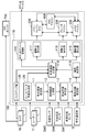
- FIG. 1 It is a figure which shows schematic the structure of the vehicle controlled by the vehicle running control device which concerns on an exemplary embodiment. It is a schematic diagram which shows the structure of an engine. It is a block diagram which shows the control system of an automobile. This is a configuration example of an arithmetic unit. It is a block diagram which shows the configuration example of a body system device control part and its surroundings.
- devices such as “traveling devices” and “body devices” refer to devices such as actuators and sensors mounted on a vehicle.
- FIG. 1 schematically shows a configuration of a vehicle 1 controlled by a vehicle travel control device 100 (hereinafter, referred to as a travel control device 100) according to the present embodiment.
- the vehicle 1 is a vehicle capable of manual driving that runs in response to an operation of the accelerator or the like by the driver, assisted driving that runs by assisting the driver's operation, and automatic driving that runs without the driver's operation. is there.
- the vehicle 1 includes an engine 10 as a drive source having a plurality of (four in this embodiment) cylinders 11, a transmission 20 connected to the engine 10, and a brake device 30 for braking the rotation of the front wheels 50 as drive wheels. And a steering device 40 for steering the front wheels 50 as steering wheels.
- the engine 10 is, for example, a gasoline engine. As shown in FIG. 2, each cylinder 11 of the engine 10 has an ignition plug 13 for igniting an injector 12 that supplies fuel into the cylinder 11 and an air-fuel mixture of the fuel and the intake air supplied into the cylinder 11. And are provided respectively. Further, the engine 10 is provided with an intake valve 14, an exhaust valve 15, and a valve operating mechanism 16 for adjusting the opening / closing operation of the intake valve 14 and the exhaust valve 15 for each cylinder 11. Further, the engine 10 is provided with a piston 17 that reciprocates in the cylinder 11 and a crankshaft 18 that is connected to the piston 17 via a connecting rod. The engine 10 may be a diesel engine. When the engine 10 is a diesel engine, the spark plug 13 may not be provided. The injector 12, the spark plug 13, and the valve operating mechanism 16 are examples of powertrain-related devices.
- the transmission 20 is, for example, a stepped automatic transmission.
- the transmission 20 is arranged on one side of the engine 10 in the cylinder row direction.
- the transmission 20 includes an input shaft (not shown) connected to the crankshaft 18 of the engine 10 and an output shaft (not shown) connected to the input shaft via a plurality of reduction gears (not shown). There is.
- the output shaft is connected to the axle 51 of the front wheel 50.
- the rotation of the crankshaft 18 is changed by the transmission 20 and transmitted to the front wheels 50.
- the transmission 20 is an example of a powertrain related device.
- the engine 10 and the transmission 20 are power train devices that generate a driving force for driving the vehicle 1.
- the operation of the engine 10 and the transmission 20 is controlled by the power train ECU (Electric Control Unit) 200.
- the power train ECU 200 uses fuel by the injector 12 based on a detection value of the accelerator opening sensor SW1 or the like that detects the accelerator opening corresponding to the operation amount of the accelerator pedal of the driver.
- the injection amount, fuel injection timing, ignition timing by the spark plug 13, and valve opening timing and valve opening period of the intake and exhaust valves 14 and 15 by the power valve mechanism 16 are controlled.
- the power train ECU 200 determines the transmission 20 based on the detection result of the shift sensor SW2 that detects the operation of the shift lever by the driver and the required driving force calculated from the accelerator opening. Adjust the gear stage. Further, when the vehicle 1 is assisted driving or automatic driving, the power train ECU 200 basically achieves the target driving force calculated by the arithmetic unit 110 described later, so that each traveling device (here, here,) is achieved. The control amount of the injector 12 and the like) is calculated, and the control signal is output to each traveling device.
- the powertrain ECU 200 is an example of a device control device.
- the brake device 30 includes a brake pedal 31, a brake actuator 33, a booster 34 connected to the brake actuator 33, a master cylinder 35 connected to the booster 34, and a DSC (Dynamic Stability Control) for adjusting the braking force. It has a device 36 and a brake pad 37 that actually brakes the rotation of the front wheel 50. A disc rotor 52 is provided on the axle 51 of the front wheel 50.
- the brake device 30 is an electric brake, and operates the brake actuator 33 according to the operation amount of the brake pedal 31 detected by the brake sensor SW3, and operates the brake pad 36 via the booster 34 and the master cylinder 35.
- the brake device 30 sandwiches the disc rotor 52 with the brake pads 37, and brakes the rotation of the front wheels 50 by the frictional force generated between the brake pads 37 and the disc rotor 52.
- the brake actuator 33 and the DSC device 36 are examples of brake-related devices.
- the operation of the brake device 30 is controlled by the brake microcomputer 300 and the DSC microcomputer 400.
- the brake microcomputer 300 controls the operation amount of the brake actuator 33 based on the detection value of the brake sensor SW3 or the like that detects the operation amount of the brake pedal 31 of the driver.
- the DSC microcomputer 400 operates and controls the DSC device 36 regardless of the operation of the driver's brake pedal 31, and applies braking force to the front wheels 50.
- the brake microcomputer 300 basically achieves the target braking force calculated by the arithmetic unit 110 described later, so that each traveling device (here, here,) is achieved.
- the control amount of the brake actuator 33) is calculated, and a control signal is output to each traveling device.
- the brake microcomputer 300 and the DSC microcomputer 400 are examples of device control devices.
- the brake microcomputer 300 and the DSC microcomputer 400 may be configured by one microcomputer.
- the steering device 40 includes a steering wheel 41 operated by the driver, an ENAS (Electronic Power Asist Steering) device 42 that assists the steering operation by the driver, and a pinion shaft 43 connected to the ENAS device 42.
- the ENAS device 42 includes an electric motor 42a and a speed reducing device 42b that reduces the driving force of the electric motor 42a and transmits it to the pinion shaft 43.
- the steering device 40 is a steer-by-wire type steering device, and operates the EPAS device 42 according to the operation amount of the steering wheel 41 detected by the steering angle sensor SW4 to rotate the pinion shaft 43 to operate the front wheels 50. To do.
- the pinion shaft 43 and the front wheel 50 are connected by a rack bar (not shown), and the rotation of the pinion shaft 43 is transmitted to the front wheels via the rack bar.
- the ENAS device 42 is an example of a steering-related device.
- the operation of the steering device 40 is controlled by the EPAS microcomputer 500.
- the EPAS microcomputer 500 controls the operation amount of the electric motor 42a based on the detection value of the steering angle sensor SW4 or the like.
- the ENAS microcomputer 500 basically achieves each traveling device (here, the target steering angle calculated by the arithmetic unit 110 described later) so as to achieve the target steering angle.
- the control amount of the EPAS device 42) is calculated, and a control signal is output to each traveling device.
- the ECAS microcomputer 500 is an example of a device control device.
- the power train ECU 200, the brake microcomputer 300, the DSC microcomputer 400, and the ENAS microcomputer 500 are configured to be able to communicate with each other.
- the powertrain ECU 200, the brake microcomputer 300, the DSC microcomputer 400, and the ENAS microcomputer 500 may be simply referred to as a device control device.
- the travel control device 100 calculates a route to be traveled by the vehicle 1 in order to enable assisted driving and automatic driving, and is a vehicle for following the route. It has an arithmetic unit 110 that determines the motion of 1.
- the arithmetic unit 110 is a microprocessor composed of one or a plurality of chips, and has a CPU, a memory, and the like. It should be noted that FIG. 3 shows a configuration for exerting the function (path generation function described later) according to the present embodiment, and does not show all the functions of the arithmetic unit 110.
- FIG. 4 is a configuration example of the arithmetic unit 110.
- the arithmetic unit 110 includes a processor 3 and a memory 4.
- the memory 4 stores a module that is software that can be executed by the processor 3.
- the functions of the respective parts shown in FIG. 3 are realized by the processor 3 executing each module stored in the memory 4.
- the memory 4 stores data representing a model used for processing by each part shown in FIG. There may be a plurality of processors 3 and memories 4.
- the arithmetic unit 110 determines the target motion of the vehicle 1 based on the outputs from a plurality of sensors and the like, and controls the operation of the device.
- Sensors and the like that output information to the arithmetic unit 110 are provided on the body and the like of the vehicle 1 and a plurality of cameras 70 for photographing the environment outside the vehicle, and a plurality of sensors and the like provided on the body of the vehicle 1 and detecting a target and the like outside the vehicle.
- the position sensor SW5 that detects the position (vehicle position information) of the vehicle 1 by using the radar 71 of the above and the Global Positioning System (GPS), and the vehicle such as the vehicle speed sensor, the acceleration sensor, and the yaw rate sensor.
- GPS Global Positioning System
- the arithmetic unit 110 is input with the communication information received by the external communication unit 72 from another vehicle located around the own vehicle and the traffic information from the navigation system.
- Each camera 70 is arranged so that the circumference of the vehicle 1 can be photographed 360 ° in the horizontal direction. Each camera 70 captures an optical image showing the environment outside the vehicle and generates image data. Each camera 70 outputs the generated image data to the arithmetic unit 110.
- the camera 70 is an example of an information acquisition means for acquiring information on the environment outside the vehicle.
- the image data acquired by each camera 70 is input to the HMI (Human Machine Interface) unit 700 in addition to the arithmetic unit 110.
- the HMI unit 700 displays information based on the acquired image data on a display device or the like in the vehicle.
- each radar 71 is arranged so that the detection range extends 360 ° horizontally around the vehicle 1.
- the type of radar 71 is not particularly limited, and for example, a millimeter wave radar or an infrared radar can be adopted.
- the radar 71 is an example of an information acquisition means for acquiring information on the environment outside the vehicle.
- the arithmetic unit 110 sets the travel path of the vehicle 1 during assisted driving or automatic driving, and sets the target motion of the vehicle 1 so that the vehicle 1 follows the traveling route.
- the computing device 110 responds to the vehicle exterior environment certification unit 111 that certifies the vehicle exterior environment based on the output from the camera 70 or the like and the vehicle exterior environment certified by the vehicle exterior environment certification unit 111.
- the candidate route generation unit 112 that calculates one or more candidate routes on which the vehicle 1 can travel, the vehicle behavior estimation unit 113 that estimates the behavior of the vehicle 1 based on the output from the vehicle state sensor SW6, and the vehicle behavior estimation unit 113.
- the occupant behavior estimation unit 114 that estimates the behavior of the occupant of the vehicle 1, the route determination unit 115 that determines the route that the vehicle 1 should travel, and the route determination unit 115 are set.
- the vehicle motion determination unit 116 that determines the target motion of the vehicle 1 for following the route, and the target physical quantity that the traveling device should generate in order to achieve the target motion determined by the vehicle motion determination unit 116 (for example, , Driving force, braking force, and steering angle), the driving force calculation unit 117, the braking force calculation unit 118, and the steering angle calculation unit 119.
- the candidate route calculation unit 112, the vehicle behavior estimation unit 113, the occupant behavior estimation unit 114, and the route determination unit 115 set the route for which the vehicle 1 should travel according to the external environment certified by the external environment certification unit 111. Make up the part.
- the arithmetic unit 110 recognizes an object outside the vehicle according to a predetermined rule, and generates a rule-based route generation unit 120 that generates a traveling route that avoids the object, and the vehicle 1 is placed on a road shoulder or the like. It has a backup unit 130 that generates a traveling route for guiding to a safe area.
- the arithmetic unit 110 includes a body device control unit 140 that controls a body-related device (appropriately referred to as a body device).
- the vehicle exterior environment certification unit 111 receives the output of the camera 70, radar 71, etc. mounted on the vehicle 1 and certifies the vehicle exterior environment.
- the certified out-of-vehicle environment includes at least roads and obstacles.
- the vehicle exterior environment certification unit 111 determines the vehicle environment including roads and obstacles by comparing the three-dimensional information around the vehicle 1 with the vehicle exterior environment model based on the data of the camera 70 and the radar 71. It shall be estimated.
- the vehicle exterior environment model is, for example, a trained model generated by deep learning, and can recognize roads, obstacles, and the like with respect to three-dimensional information around the vehicle.
- the vehicle exterior environment certification unit 111 identifies a free space, that is, an area where no object exists, by image processing from the image captured by the camera 70.
- image processing for example, a trained model generated by deep learning is used.
- a two-dimensional map representing the free space is generated.
- the vehicle exterior environment certification unit 111 acquires information on the target existing around the vehicle 1 from the output of the radar 71. This information is positioning information including the position and speed of the target.
- the vehicle exterior environment certification unit 111 combines the generated two-dimensional map with the positioning information of the target to generate a three-dimensional map representing the surroundings of the vehicle 1.
- the vehicle exterior environment certification unit 111 estimates the vehicle environment including roads and obstacles by comparing the generated three-dimensional map with the vehicle exterior environment model.
- a multi-layer neural network (DNN: Deep Neural Network) is used.
- DNN Deep Neural Network
- CNN Convolutional Neural Network
- the candidate route generation unit 112 generates a candidate route on which the vehicle 1 can travel based on the output of the vehicle exterior environment certification unit 111, the output of the position sensor SW5, the information transmitted from the vehicle exterior communication unit 73, and the like. For example, the candidate route generation unit 112 generates a travel route that avoids obstacles certified by the vehicle exterior environment certification unit 111 on the road certified by the vehicle exterior environment certification unit 111.
- the output of the vehicle exterior environment certification unit 111 includes, for example, travel path information regarding the travel path on which the vehicle 1 travels.
- the travel path information includes information on the shape of the travel path itself and information on an object on the travel path.
- Information on the shape of the road includes the shape of the road (straight line, curve, curve curvature), width of the road, number of lanes, width of each lane, and the like.
- the information about the object includes the relative position and speed of the object with respect to the vehicle, the attributes (type, moving direction) of the object, and the like. Examples of the types of objects include vehicles, pedestrians, roads, lane markings, and the like.
- the candidate route generation unit 112 calculates a plurality of candidate routes by using the state lattice method, and selects one or a plurality of candidate routes from among them based on the route cost of each candidate route. And.
- the route may be calculated by using another method.
- the candidate route generation unit 112 sets a virtual grid area on the travel path based on the travel route information.
- This grid area has a plurality of grid points.
- Each grid point identifies a position on the track.
- the candidate route generation unit 112 sets a predetermined grid point at the target arrival position.
- a plurality of candidate routes are calculated by a route search using a plurality of grid points in the grid area.
- the route branches from a certain grid point to an arbitrary grid point ahead in the traveling direction of the vehicle. Therefore, each candidate route is set to sequentially pass through a plurality of grid points.
- Each candidate route also includes time information indicating the time to pass each grid point, speed information related to speed / acceleration at each grid point, and other information related to vehicle motion.
- the candidate route generation unit 112 selects one or a plurality of travel routes from a plurality of candidate routes based on the route cost.
- the route cost here includes, for example, the degree of lane centering, the acceleration of the vehicle, the steering angle, the possibility of collision, and the like.
- the route determination unit 115 selects one travel route.
- the vehicle state estimation unit 113 measures the state of the vehicle from the outputs of sensors that detect the behavior of the vehicle, such as a vehicle speed sensor, an acceleration sensor, and a yaw rate sensor.
- the vehicle state estimation unit 113 uses a vehicle 6-axis model showing the behavior of the vehicle.
- the vehicle 6-axis model is a model of the acceleration in the three-axis directions of "front-back”, “left-right”, and “up-down” of the running vehicle, and the angular velocity in the three-axis directions of "pitch", "roll”, and “yaw”. It is a product. That is, instead of capturing the movement of the vehicle only on the classical vehicle motion engineering plane (only the front-back and left-right (XY movement) and yaw movement (Z-axis) of the vehicle), the suspension is applied to the four wheels.
- the vehicle state estimation unit 113 applies the vehicle 6-axis model to the travel route generated by the candidate route generation unit 112, and estimates the behavior of the vehicle 1 when following the travel route.
- the occupant behavior estimation unit 114 estimates the driver's health condition and emotions from the detection result of the occupant condition sensor SW7.
- the health condition includes, for example, health, mild fatigue, poor physical condition, and decreased consciousness.
- Emotions include, for example, fun, normal, boring, frustrated, and uncomfortable.
- the occupant state estimation unit 114 extracts the driver's face image from the image captured by the camera installed in the vehicle interior, and identifies the driver.
- the extracted face image and the identified driver information are given as inputs to the human model.
- the human model is, for example, a trained model generated by deep learning, and outputs the health state and emotions from the face image of each person who can be the driver of the vehicle 1.
- the occupant state estimation unit 114 outputs the driver's health state and emotions output by the human model.
- the occupant state estimation unit 114 uses the biometric information.
- the driver's biological information is measured from the output of the sensor.
- the human model inputs the biometric information of each person who can be the driver of the vehicle 1 and outputs the health state and emotions.
- the occupant state estimation unit 114 outputs the driver's health state and emotions output by the human model.
- a model for estimating the emotions that a human has with respect to the behavior of the vehicle 1 may be used for each person who can be the driver of the vehicle 1.
- the output of the vehicle behavior estimation unit 113, the driver's biological information, and the estimated emotional state may be managed in chronological order to build a model.
- this model for example, it is possible to predict the relationship between the driver's emotional increase (alertness) and the behavior of the vehicle.
- the occupant state estimation unit 114 may include a human body model as a human model.
- the human body model specifies, for example, the mass of the head (eg, 5 kg) and the muscle strength around the neck that supports the front, back, left, and right G.
- the human body model inputs the movement of the vehicle body (acceleration G or jerk), it outputs the expected physical and subjective occupants.
- the physical occupants are, for example, comfortable / moderate / unpleasant, and the subjective ones are, for example, unexpected / predictable.
- the human body model for example, the vehicle body behavior in which the head is slightly turned upside down is unpleasant for the occupant, so that the traveling route can be prevented from being selected.
- the vehicle body behavior in which the head moves forward as if bowing makes it easy for the occupant to take a posture against this and does not immediately lead to discomfort, so that the traveling route can be selected.
- the target movement can be dynamically determined so that the occupant's head does not shake or is lively.
- the occupant state estimation unit 114 applies a human model to the vehicle behavior estimated by the vehicle behavior estimation unit 113, and estimates changes in the health condition and emotions of the current driver with respect to the vehicle behavior.
- the route determination unit 115 determines the route on which the vehicle 1 should travel based on the output of the occupant state estimation unit 114. When the candidate route generation unit 112 has generated one route, the route determination unit 115 sets the route as the route on which the vehicle 1 should travel. When there are a plurality of routes generated by the candidate route generation unit 112, in consideration of the output of the occupant state estimation unit 114, for example, the route that the occupant (particularly the driver) feels most comfortable among the plurality of candidate routes, that is, Select a route that does not make the driver feel redundant, such as being too careful in avoiding obstacles.
- the rule-based route generation unit 120 Based on the output from the camera 70 and the radar 71, the rule-based route generation unit 120 recognizes an object outside the vehicle according to a predetermined rule without using deep learning, and travels so as to avoid the object. Generate a route. Similar to the candidate route generation unit 112, the rule-based route generation unit 120 also calculates a plurality of candidate routes using the state lattice method, and one or more of these based on the route cost of each candidate route. The candidate route of is selected. In the rule-based route generation unit 120, for example, the route cost is calculated based on the rule that the object does not enter within a few meters around the object. The rule-based route generation unit 120 may also calculate the route by using another method.
- the route information generated by the rule-based route generation unit 120 is input to the vehicle motion determination unit 116.
- the backup unit 130 Based on the outputs from the camera 70 and the radar 71, the backup unit 130 generates a traveling route for guiding the vehicle 1 to a safe area such as a road shoulder when the sensor or the like fails or the occupant is not in good physical condition. ..
- the backup unit 130 sets a safety area in which the vehicle 1 can be stopped urgently from the information of the position sensor SW5, and generates a traveling route until the vehicle 1 reaches the safety area.
- the backup unit 130 Similar to the candidate route generation unit 112, the backup unit 130 also calculates a plurality of candidate routes using the state lattice method, and one or a plurality of candidate routes from among these based on the route cost of each candidate route. Shall be selected.
- the backup unit 130 may also calculate the route by using another method.
- the route information generated by the backup unit 130 is input to the vehicle motion determination unit 116.
- the vehicle motion determination unit 116 determines the target motion for the travel route determined by the route determination unit 115.
- the target motion refers to steering and acceleration / deceleration that follow the traveling path. Further, the vehicle motion determination unit 116 calculates the movement of the vehicle body with respect to the traveling route selected by the route determination unit 115 with reference to the vehicle 6-axis model.
- the vehicle motion determination unit 116 determines the target motion for following the travel path generated by the rule-based route generation unit 120.
- the vehicle motion determination unit 116 determines the target motion for following the travel path generated by the backup unit 130.
- the vehicle motion determination unit 116 travels generated by the rule-based route generation unit 120.
- the route is selected as the route that the vehicle 1 should travel.
- the vehicle motion determination unit 116 uses the travel route generated by the backup unit 130 as the route that the vehicle 1 should travel. select.
- the physical quantity calculation unit includes a driving force calculation unit 117, a braking force calculation unit 118, and a steering angle calculation unit 119.
- the driving force calculation unit 117 calculates the target driving force to be generated by the power train device (engine 10 and transmission 20) in order to achieve the target motion.
- the braking force calculation unit 118 calculates the target braking force to be generated by the braking device 30 in order to achieve the target motion.
- the steering angle calculation unit 119 calculates a target steering angle to be generated by the steering device 40 in order to achieve the target motion.
- the arithmetic unit 110 has a function of controlling a body-related device (body-based device). That is, the body device control unit 140 sets the operation of the body device of the vehicle 1 such as a lamp and the door based on the output of the vehicle motion determination unit 116, and controls the body device according to the setting. To generate. The generated control signal is transmitted to each body device. As a result, the number of microcomputers that control each body device can be significantly reduced. In addition, communication between body devices can be speeded up.
- body-based device body-based device
- FIG. 5 is a block diagram showing a configuration example of the body device control unit 140 and its surroundings.
- the operation setting unit 141 sets, for example, the direction of the lamp when the vehicle 1 follows the travel path determined by the route determination unit 115.
- the lamps control unit 151 receives an instruction regarding the direction of the lamp from the operation setting unit 141, the lamp control unit 151 transmits a control signal for setting the direction to the lamp. Further, for example, when the operation setting unit 141 guides the vehicle 1 to the safety area set by the bup-up unit 130, after the vehicle reaches the safety area, the hazard lamp is turned on or the door is unlocked. Set the operation to do.
- the lamps control unit 151 When the lamps control unit 151 receives an instruction to turn on the hazard lamp from the operation setting unit 141, the lamp control unit 151 transmits a control signal to turn on the hazard lamp.
- the door control unit 152 receives an instruction to unlock the door from the operation setting unit 141, the door control unit 152 transmits a control signal for unlocking the door to the door.
- Other body devices include, for example, windows, horns, pretensioners and the like.
- a control device may be provided separately from the arithmetic unit 110.
- the airbag deployment microcomputer 600 is provided separately from the arithmetic unit 110 for the airbag.
- the airbag deployment microcomputer 600 is an example of a body device control device.
- the control function of the body device into the arithmetic unit 110, it is possible to accelerate the standby of the body device according to the prediction of the behavior of the vehicle. For example, when the possibility of a collision is predicted, the pretensioner can be operated weakly.
- a special harness is set for the hazard lamps in order to match the blinking timing of the hazard lamps placed on the front, rear, left and right and the door mirrors. Additional hardware was required, such as enabling current on / off with a single relay.
- the body device control unit 140 is responsible for supplying power to a plurality of hazard lamps, the blinking timing can be easily improved.
- the door lock is released by receiving the radio wave emitted by the owner's smart key approaching the parked vehicle, and the interior lamp is turned on as a welcome lamp to gradually increase the illumination, and the driver handles the door handle.
- hospitality control that continuously operates a series of body devices, such as displaying a brand icon on the display of the center console when the door is started to open by pulling.
- body microcomputers are distributed in each zone of the vehicle, in order to realize this control, the power is turned on in order in each zone of the vehicle, and the startup time is estimated so that each device operates continuously. It was necessary to perform complicated control to command each microcomputer via the in-vehicle network, such as wake-up in advance.
- the body device control unit 140 supervises and activates each device by turning on the power, hospitality control can be easily realized. Further, the specification change of the hospitality control can be easily realized by rewriting the program of the body device control unit 140.
- the calculation result of the arithmetic unit 110 is output to the power train ECU 200, the brake microcomputer 300, the ENAS microcomputer 500, and the body system microcomputer 700.
- information on the target driving force calculated by the driving force calculation unit 117 is input to the power train ECU 200, and information on the target braking force calculated by the braking force calculation unit 118 is input to the brake microcomputer 300.
- Information on the target steering angle calculated by the steering angle calculation unit 119 is input to the ENAS microcomputer 500.
- the arithmetic unit 100 sends a control signal generated by the body device control unit 140 to each body device such as a door or a lamp.
- the power train ECU 200 basically calculates the fuel injection timing of the injector 12 and the ignition timing of the spark plug 13 so as to achieve the target driving force, and sends control signals to these traveling devices. Is output.
- the brake microcomputer 300 basically calculates the control amount of the brake actuator 33 so as to achieve the target driving force, and outputs a control signal to the brake actuator 33.
- the ENAS microcomputer 500 basically calculates the amount of current supplied to the ENAS device 42 so as to achieve the target steering angle, and outputs a control signal to the ENAS device 42.
- the arithmetic unit 110 only calculates the target physical quantity to be output by each traveling device, and the control amount of each traveling device is calculated by each device control device 200 to 500. ..
- the amount of calculation of the arithmetic unit 110 can be reduced, and the calculation speed of the arithmetic unit 110 can be improved.
- the processing speed is high. As a result, the responsiveness of the traveling device to the environment outside the vehicle can be improved.
- the arithmetic unit 110 may calculate a rough physical quantity by causing each device control device 200 to 500 to calculate the control amount, the arithmetic speed is slower than that of each device control device 200 to 500. It will be good. As a result, the calculation accuracy of the arithmetic unit 110 can be improved.
- the arithmetic unit 110 and the device control devices 200 to 500 for operating and controlling the traveling device (injector 12, etc.) mounted on the vehicle 1 based on the arithmetic result of the arithmetic unit 110 are provided.
- the arithmetic unit 110 has an external environment certification unit 111 that certifies the external environment based on the outputs from the camera 70 and the radar 71 that acquire information on the external environment, and the external environment certification unit 111 that certifies the external environment.
- a route setting unit (route calculation unit 112, etc.) that sets a route on which the vehicle 1 should travel, a vehicle motion determination unit 116 that determines a target motion of the vehicle 1 for following the route set by the route setting unit, and a vehicle.
- the arithmetic unit 110 includes a body device control unit 140 that sets the operation of the body device of the vehicle based on the output of the motion determination unit 116 and generates a control signal for controlling the body device.
- the arithmetic unit 110 includes a body device control unit 140 that controls the body device of the vehicle, in addition to the function of executing the calculation for operating the traveling device mounted on the vehicle.
- the control function of the body device is incorporated into the arithmetic unit 110, so that the number of microcomputers that control the body device can be significantly reduced.
- communication between body devices can be speeded up. Further, in the body device, the standby can be accelerated according to the behavior prediction of the vehicle.
- the vehicle travel control device 100 includes device control devices 200 to 500 for operating and controlling the travel device in addition to the arithmetic unit 110, the control function of the travel device is not incorporated in the arithmetic unit 110. It is possible to suppress an increase in the arithmetic load of the arithmetic unit 110.
- the arithmetic unit 110 includes physical quantity calculation units 117 to 119 for calculating a target physical quantity to be generated by the traveling device in order to achieve the target motion determined by the vehicle motion determination unit 116, and is a device control device.
- the 200 to 500 calculate the control amount of the traveling device so as to achieve the target physical quantity calculated by the physical quantity calculation units 117 to 119, and output a control signal to the traveling device.
- the arithmetic unit 110 only calculates the physical quantity to be achieved, and the device control devices 200 to 500 calculate the actual control amount of the traveling device.
- the amount of calculation of the arithmetic unit 110 can be reduced, and the calculation speed of the arithmetic unit 110 can be improved.
- the processing speed is high. As a result, the responsiveness of the traveling device to the environment outside the vehicle can be improved.
- the vehicle exterior environment certification unit 111 certifies the vehicle exterior environment using deep learning, and the arithmetic unit 110 has a particularly large amount of calculation. Therefore, if the control amount of the traveling device is calculated by the device control devices 200 to 500 other than the arithmetic unit 110, the effect of further improving the responsiveness of the traveling device to the outside environment is more appropriately exhibited. can do.
- the driving force calculation unit 117, the braking force calculation unit 118, and the steering angle calculation unit 119 may change the target driving force or the like according to the state of the driver of the vehicle 1 during the assist driving of the vehicle 1. For example, when the driver is enjoying driving (the driver's emotions are "fun"), the target driving force or the like may be reduced to make the driving as close to manual driving as possible. On the other hand, when the driver is in a state of poor physical condition, the target driving force or the like may be increased so as to approach automatic driving as much as possible.
- the route determination unit 115 determines the route on which the vehicle 1 should travel.
- the route determination unit 115 may be omitted, and the vehicle motion determination unit 116 may determine the route on which the vehicle 1 should travel. That is, the vehicle motion determination unit 116 may concurrently serve as a part of the route setting unit and the target motion determination unit.
- the driving force calculation unit 117, the braking force calculation unit 118, and the steering angle calculation unit 119 have calculated the target physical quantity such as the target driving force.
- the vehicle motion determination unit 116 may calculate the target physical quantity by omitting the driving force calculation unit 117, the braking force calculation unit 118, and the steering angle calculation unit 119. That is, the vehicle motion determination unit 116 may concurrently serve as the target motion determination unit and the physical quantity calculation unit.
- the technology disclosed here is useful as a vehicle travel control device that controls the travel of the vehicle.
Landscapes
- Engineering & Computer Science (AREA)
- Automation & Control Theory (AREA)
- Transportation (AREA)
- Mechanical Engineering (AREA)
- Human Computer Interaction (AREA)
- Physics & Mathematics (AREA)
- Mathematical Physics (AREA)
- Control Of Driving Devices And Active Controlling Of Vehicle (AREA)
- Traffic Control Systems (AREA)
Abstract
La présente invention concerne un appareil de commande de déplacement de véhicule (100) comprenant une unité de calcul (110) et des appareils de commande de dispositif (200, 300, 400, 500) qui commandent les actions de dispositifs de déplacement installés dans un véhicule. L'unité de calcul (110) est dotée d'une unité de reconnaissance d'environnement externe (111) qui reconnaît un environnement externe, d'unités de réglage d'itinéraire (112, 113, 114, 115) qui définissent un itinéraire sur lequel le véhicule doit se déplacer, d'une unité de détermination de mouvement de véhicule (116) qui détermine un mouvement cible par lequel le véhicule va suivre l'itinéraire cible défini et d'une unité de commande de dispositif associé au corps (140) qui définit une action d'un dispositif associé au corps du véhicule et génère un signal de commande destiné à commander le dispositif associé au corps sur la base de la sortie de l'unité de détermination de mouvement de véhicule (116).
Priority Applications (3)
| Application Number | Priority Date | Filing Date | Title |
|---|---|---|---|
| CN202080011212.3A CN113597394A (zh) | 2019-03-29 | 2020-03-06 | 车辆行驶控制装置 |
| EP20783254.4A EP3909824B1 (fr) | 2019-03-29 | 2020-03-06 | Appareil de commande de déplacement de véhicule |
| US17/482,448 US20220009485A1 (en) | 2019-03-29 | 2021-09-23 | Vehicle travel control device |
Applications Claiming Priority (2)
| Application Number | Priority Date | Filing Date | Title |
|---|---|---|---|
| JP2019066763A JP7243389B2 (ja) | 2019-03-29 | 2019-03-29 | 車両走行制御装置 |
| JP2019-066763 | 2019-03-29 |
Related Child Applications (1)
| Application Number | Title | Priority Date | Filing Date |
|---|---|---|---|
| US17/482,448 Continuation US20220009485A1 (en) | 2019-03-29 | 2021-09-23 | Vehicle travel control device |
Publications (1)
| Publication Number | Publication Date |
|---|---|
| WO2020203054A1 true WO2020203054A1 (fr) | 2020-10-08 |
Family
ID=72668600
Family Applications (1)
| Application Number | Title | Priority Date | Filing Date |
|---|---|---|---|
| PCT/JP2020/009774 WO2020203054A1 (fr) | 2019-03-29 | 2020-03-06 | Appareil de commande de déplacement de véhicule |
Country Status (5)
| Country | Link |
|---|---|
| US (1) | US20220009485A1 (fr) |
| EP (1) | EP3909824B1 (fr) |
| JP (1) | JP7243389B2 (fr) |
| CN (1) | CN113597394A (fr) |
| WO (1) | WO2020203054A1 (fr) |
Citations (3)
| Publication number | Priority date | Publication date | Assignee | Title |
|---|---|---|---|---|
| JP2017061278A (ja) | 2015-09-25 | 2017-03-30 | 株式会社デンソー | 制御システム |
| JP2017182347A (ja) * | 2016-03-29 | 2017-10-05 | 株式会社オートネットワーク技術研究所 | 車両用通信システム、車両周辺情報送信方法及び制御プログラム |
| WO2018134901A1 (fr) * | 2017-01-18 | 2018-07-26 | 本田技研工業株式会社 | Dispositif de commande de véhicule |
Family Cites Families (19)
| Publication number | Priority date | Publication date | Assignee | Title |
|---|---|---|---|---|
| JP4193703B2 (ja) | 2004-01-19 | 2008-12-10 | トヨタ自動車株式会社 | 物体検出装置 |
| JP6331975B2 (ja) * | 2014-10-31 | 2018-05-30 | 株式会社デンソー | 停車時車両制御装置 |
| JP6745698B2 (ja) * | 2016-09-30 | 2020-08-26 | 株式会社Subaru | 車両の乗員保護装置 |
| KR102064220B1 (ko) * | 2017-07-06 | 2020-01-09 | 엘지전자 주식회사 | 차량용 주행 시스템 및 차량 |
| WO2019078010A1 (fr) * | 2017-10-18 | 2019-04-25 | ソニー株式会社 | Dispositif de traitement d'informations, procédé de traitement d'informations, corps mobile et véhicule |
| JP6938353B2 (ja) * | 2017-12-12 | 2021-09-22 | 矢崎総業株式会社 | 車載システム |
| US11400834B2 (en) * | 2018-02-02 | 2022-08-02 | State Farm Mutual Automobile Insurance Company | Adjusting interior configuration of a vehicle based on external environment data |
| JP6972294B2 (ja) * | 2018-02-26 | 2021-11-24 | 本田技研工業株式会社 | 車両制御システム、車両制御方法、およびプログラム |
| US11040619B1 (en) * | 2018-04-05 | 2021-06-22 | Ambarella International Lp | Limiting car behavior based on a pre-set driver profile enabled by face recognition |
| JP2020052559A (ja) * | 2018-09-25 | 2020-04-02 | 本田技研工業株式会社 | 車両制御装置、車両制御方法、及びプログラム |
| CN109455180B (zh) * | 2018-11-09 | 2020-10-16 | 百度在线网络技术(北京)有限公司 | 用于控制无人车的方法和装置 |
| EP3882884A4 (fr) * | 2018-11-13 | 2022-01-05 | Sony Group Corporation | Dispositif de traitement d'informations, procédé de traitement d'informations et programme |
| US10771787B2 (en) * | 2018-11-30 | 2020-09-08 | Toyota Motor North America, Inc. | Dynamic data compression systems and methods for use with vehicle data |
| US10962372B1 (en) * | 2018-12-31 | 2021-03-30 | Accelerate Labs, Llc | Navigational routes for autonomous vehicles |
| US11001231B1 (en) * | 2019-02-28 | 2021-05-11 | Ambarella International Lp | Using camera data to manage a vehicle parked outside in cold climates |
| JP7145105B2 (ja) * | 2019-03-04 | 2022-09-30 | 本田技研工業株式会社 | 車両制御システム、車両制御方法、およびプログラム |
| US11468582B2 (en) * | 2019-03-16 | 2022-10-11 | Nvidia Corporation | Leveraging multidimensional sensor data for computationally efficient object detection for autonomous machine applications |
| US11351991B2 (en) * | 2019-03-25 | 2022-06-07 | Zoox, Inc. | Prediction based on attributes |
| JP2020160705A (ja) * | 2019-03-26 | 2020-10-01 | 本田技研工業株式会社 | 車両制御装置、車両制御方法、およびプログラム |
-
2019
- 2019-03-29 JP JP2019066763A patent/JP7243389B2/ja active Active
-
2020
- 2020-03-06 WO PCT/JP2020/009774 patent/WO2020203054A1/fr unknown
- 2020-03-06 EP EP20783254.4A patent/EP3909824B1/fr active Active
- 2020-03-06 CN CN202080011212.3A patent/CN113597394A/zh active Pending
-
2021
- 2021-09-23 US US17/482,448 patent/US20220009485A1/en active Pending
Patent Citations (3)
| Publication number | Priority date | Publication date | Assignee | Title |
|---|---|---|---|---|
| JP2017061278A (ja) | 2015-09-25 | 2017-03-30 | 株式会社デンソー | 制御システム |
| JP2017182347A (ja) * | 2016-03-29 | 2017-10-05 | 株式会社オートネットワーク技術研究所 | 車両用通信システム、車両周辺情報送信方法及び制御プログラム |
| WO2018134901A1 (fr) * | 2017-01-18 | 2018-07-26 | 本田技研工業株式会社 | Dispositif de commande de véhicule |
Also Published As
| Publication number | Publication date |
|---|---|
| JP7243389B2 (ja) | 2023-03-22 |
| EP3909824A4 (fr) | 2022-03-09 |
| US20220009485A1 (en) | 2022-01-13 |
| CN113597394A (zh) | 2021-11-02 |
| JP2020164044A (ja) | 2020-10-08 |
| EP3909824B1 (fr) | 2023-11-01 |
| EP3909824A1 (fr) | 2021-11-17 |
Similar Documents
| Publication | Publication Date | Title |
|---|---|---|
| WO2020203058A1 (fr) | Système de commande de déplacement pour véhicule | |
| WO2020203055A1 (fr) | Dispositif de commande de déplacement de véhicule | |
| WO2020203078A1 (fr) | Dispositif de calcul pour commande de déplacement de véhicule et système de commande de déplacement utilisant ce dernier | |
| WO2020203057A1 (fr) | Dispositif de commande de déplacement de véhicule | |
| WO2020184277A1 (fr) | Système d'opération arithmétique pour véhicule | |
| WO2020203068A1 (fr) | Appareil de commande de déplacement de véhicule | |
| WO2020203054A1 (fr) | Appareil de commande de déplacement de véhicule | |
| WO2020246098A1 (fr) | Système de réseau dans un véhicule | |
| WO2020246100A1 (fr) | Système de réseau monté sur véhicule | |
| JP2020142761A (ja) | 車両用演算システム | |
| JP7392293B2 (ja) | 車両の故障診断装置 | |
| JP7434714B2 (ja) | 車両用演算システム | |
| JP2020142760A (ja) | 車両用演算システム |
Legal Events
| Date | Code | Title | Description |
|---|---|---|---|
| 121 | Ep: the epo has been informed by wipo that ep was designated in this application |
Ref document number: 20783254 Country of ref document: EP Kind code of ref document: A1 |
|
| ENP | Entry into the national phase |
Ref document number: 2020783254 Country of ref document: EP Effective date: 20210812 |
|
| NENP | Non-entry into the national phase |
Ref country code: DE |