WO2020195066A1 - 車載通信システム、車載中継装置及び車載制御装置 - Google Patents
車載通信システム、車載中継装置及び車載制御装置 Download PDFInfo
- Publication number
- WO2020195066A1 WO2020195066A1 PCT/JP2020/002145 JP2020002145W WO2020195066A1 WO 2020195066 A1 WO2020195066 A1 WO 2020195066A1 JP 2020002145 W JP2020002145 W JP 2020002145W WO 2020195066 A1 WO2020195066 A1 WO 2020195066A1
- Authority
- WO
- WIPO (PCT)
- Prior art keywords
- communication
- auxiliary
- control device
- vehicle
- main
- Prior art date
- Legal status (The legal status is an assumption and is not a legal conclusion. Google has not performed a legal analysis and makes no representation as to the accuracy of the status listed.)
- Ceased
Links
Images


Classifications
-
- B—PERFORMING OPERATIONS; TRANSPORTING
- B60—VEHICLES IN GENERAL
- B60W—CONJOINT CONTROL OF VEHICLE SUB-UNITS OF DIFFERENT TYPE OR DIFFERENT FUNCTION; CONTROL SYSTEMS SPECIALLY ADAPTED FOR HYBRID VEHICLES; ROAD VEHICLE DRIVE CONTROL SYSTEMS FOR PURPOSES NOT RELATED TO THE CONTROL OF A PARTICULAR SUB-UNIT
- B60W50/00—Details of control systems for road vehicle drive control not related to the control of a particular sub-unit, e.g. process diagnostic or vehicle driver interfaces
- B60W50/02—Ensuring safety in case of control system failures, e.g. by diagnosing, circumventing or fixing failures
- B60W50/023—Avoiding failures by using redundant parts
-
- H—ELECTRICITY
- H04—ELECTRIC COMMUNICATION TECHNIQUE
- H04L—TRANSMISSION OF DIGITAL INFORMATION, e.g. TELEGRAPHIC COMMUNICATION
- H04L12/00—Data switching networks
- H04L12/28—Data switching networks characterised by path configuration, e.g. LAN [Local Area Networks] or WAN [Wide Area Networks]
- H04L12/40—Bus networks
- H04L12/40169—Flexible bus arrangements
- H04L12/40176—Flexible bus arrangements involving redundancy
- H04L12/40189—Flexible bus arrangements involving redundancy by using a plurality of bus systems
-
- B—PERFORMING OPERATIONS; TRANSPORTING
- B60—VEHICLES IN GENERAL
- B60R—VEHICLES, VEHICLE FITTINGS, OR VEHICLE PARTS, NOT OTHERWISE PROVIDED FOR
- B60R16/00—Electric or fluid circuits specially adapted for vehicles and not otherwise provided for; Arrangement of elements of electric or fluid circuits specially adapted for vehicles and not otherwise provided for
- B60R16/02—Electric or fluid circuits specially adapted for vehicles and not otherwise provided for; Arrangement of elements of electric or fluid circuits specially adapted for vehicles and not otherwise provided for electric constitutive elements
- B60R16/023—Electric or fluid circuits specially adapted for vehicles and not otherwise provided for; Arrangement of elements of electric or fluid circuits specially adapted for vehicles and not otherwise provided for electric constitutive elements for transmission of signals between vehicle parts or subsystems
- B60R16/0231—Circuits relating to the driving or the functioning of the vehicle
-
- B—PERFORMING OPERATIONS; TRANSPORTING
- B60—VEHICLES IN GENERAL
- B60W—CONJOINT CONTROL OF VEHICLE SUB-UNITS OF DIFFERENT TYPE OR DIFFERENT FUNCTION; CONTROL SYSTEMS SPECIALLY ADAPTED FOR HYBRID VEHICLES; ROAD VEHICLE DRIVE CONTROL SYSTEMS FOR PURPOSES NOT RELATED TO THE CONTROL OF A PARTICULAR SUB-UNIT
- B60W50/00—Details of control systems for road vehicle drive control not related to the control of a particular sub-unit, e.g. process diagnostic or vehicle driver interfaces
- B60W50/02—Ensuring safety in case of control system failures, e.g. by diagnosing, circumventing or fixing failures
- B60W50/0205—Diagnosing or detecting failures; Failure detection models
-
- B—PERFORMING OPERATIONS; TRANSPORTING
- B60—VEHICLES IN GENERAL
- B60W—CONJOINT CONTROL OF VEHICLE SUB-UNITS OF DIFFERENT TYPE OR DIFFERENT FUNCTION; CONTROL SYSTEMS SPECIALLY ADAPTED FOR HYBRID VEHICLES; ROAD VEHICLE DRIVE CONTROL SYSTEMS FOR PURPOSES NOT RELATED TO THE CONTROL OF A PARTICULAR SUB-UNIT
- B60W60/00—Drive control systems specially adapted for autonomous road vehicles
- B60W60/005—Handover processes
-
- H—ELECTRICITY
- H04—ELECTRIC COMMUNICATION TECHNIQUE
- H04B—TRANSMISSION
- H04B1/00—Details of transmission systems, not covered by a single one of groups H04B3/00 - H04B13/00; Details of transmission systems not characterised by the medium used for transmission
- H04B1/74—Details of transmission systems, not covered by a single one of groups H04B3/00 - H04B13/00; Details of transmission systems not characterised by the medium used for transmission for increasing reliability, e.g. using redundant or spare channels or apparatus
-
- H—ELECTRICITY
- H04—ELECTRIC COMMUNICATION TECHNIQUE
- H04B—TRANSMISSION
- H04B3/00—Line transmission systems
- H04B3/02—Details
- H04B3/36—Repeater circuits
-
- H—ELECTRICITY
- H04—ELECTRIC COMMUNICATION TECHNIQUE
- H04L—TRANSMISSION OF DIGITAL INFORMATION, e.g. TELEGRAPHIC COMMUNICATION
- H04L12/00—Data switching networks
- H04L12/28—Data switching networks characterised by path configuration, e.g. LAN [Local Area Networks] or WAN [Wide Area Networks]
- H04L12/40—Bus networks
- H04L12/40006—Architecture of a communication node
- H04L12/40045—Details regarding the feeding of energy to the node from the bus
-
- H—ELECTRICITY
- H04—ELECTRIC COMMUNICATION TECHNIQUE
- H04L—TRANSMISSION OF DIGITAL INFORMATION, e.g. TELEGRAPHIC COMMUNICATION
- H04L12/00—Data switching networks
- H04L12/28—Data switching networks characterised by path configuration, e.g. LAN [Local Area Networks] or WAN [Wide Area Networks]
- H04L12/40—Bus networks
- H04L2012/40208—Bus networks characterized by the use of a particular bus standard
- H04L2012/40215—Controller Area Network CAN
-
- H—ELECTRICITY
- H04—ELECTRIC COMMUNICATION TECHNIQUE
- H04L—TRANSMISSION OF DIGITAL INFORMATION, e.g. TELEGRAPHIC COMMUNICATION
- H04L12/00—Data switching networks
- H04L12/28—Data switching networks characterised by path configuration, e.g. LAN [Local Area Networks] or WAN [Wide Area Networks]
- H04L12/40—Bus networks
- H04L2012/40267—Bus for use in transportation systems
- H04L2012/40273—Bus for use in transportation systems the transportation system being a vehicle
Definitions
- the present disclosure relates to an in-vehicle communication system in which a plurality of devices mounted on a vehicle communicate via a communication line, and an in-vehicle relay device and an in-vehicle control device constituting this system.
- ECUs Electronic Control Units
- Each device communicates with other devices, exchanges information, and performs each process. Therefore, as the number of devices in the vehicle increases, the amount of communication lines in the vehicle provided for the devices to communicate with each other is increasing.
- Patent Document 1 the vehicle is divided into a plurality of regions, a plurality of functional ECUs are connected to the relay ECU by the first network for each region, and a plurality of relay ECUs are connected by the second network. The system is described.
- the present disclosure has been made in view of such circumstances, and an object thereof is an in-vehicle communication system, an in-vehicle relay device, and an in-vehicle control device that can be expected to improve the reliability of communication in a vehicle. To provide.
- the in-vehicle communication system is mounted on a first relay device mounted on a first area of a vehicle and a second area of the vehicle, and is mounted on the first area and the second area via a communication trunk line.
- a second relay device connected to the first relay device, and a main control device and an auxiliary device mounted in the first area and connected to the first relay device via a communication branch line to control the traveling of the vehicle.
- the first input device for inputting information used for the traveling control to the main control device or the auxiliary control device is mounted in the second area and connected to the second relay device via a communication branch line.
- the second input device that inputs information used for travel control to the main control device or the auxiliary control device via the first relay device and the second relay device, and the first relay device and the controlled device are When communication is performed via an auxiliary communication line provided across the first area and the second area, and the main control device and the auxiliary control device cannot perform communication via the communication trunk line.
- the auxiliary control device communicates with the controlled device via the auxiliary communication line, and the auxiliary control device controls the controlled device when the main control device cannot control the controlled device. Do.
- the present application can be realized not only as a device such as an in-vehicle relay device or an in-vehicle control device provided with such a characteristic processing unit, but also as a communication method in which such characteristic processing is a step, or such a step.
- the in-vehicle communication system is mounted on a first relay device mounted on a first area of a vehicle and a second area of the vehicle, and communicates across the first area and the second area.
- a second relay device connected to the first relay device via a trunk line, and a main control mounted in the first area and connected to the first relay device via a communication branch line to control traveling of the vehicle.
- a second input device that inputs information used for the traveling control to the main control device or the auxiliary control device via the first relay device and the second relay device, the first relay device, and the controlled device.
- the device may perform communication via the auxiliary communication line provided across the first area and the second area, and the main control device and the auxiliary control device may perform communication via the communication trunk line.
- the auxiliary control device communicates with the controlled device via the auxiliary communication line, and the auxiliary control device is the controlled device when the main control device cannot control the controlled device. To control.
- the area in the vehicle on which various devices such as a control device and a relay device can be mounted is divided into at least two areas, a first area and a second area.
- a main control device and an auxiliary control device for controlling the running of the vehicle, a first relay device for relaying communication, and a first input device for inputting information used for running control are mounted.
- a controlled device controlled by the control device, a second relay device for relaying communication, and a second input device for inputting information used for traveling control are mounted.
- the first relay device and the second relay device are connected via a communication trunk line across the first area and the second area.
- the first relay device and the controlled device are connected via an auxiliary communication line across the first area and the second area.
- the main control device and the auxiliary control device provided in the first area communicate with the controlled device provided in the second area through the communication path via the communication trunk line and the communication via the auxiliary communication line. It is possible to carry out by using two routes.
- the main control device and the auxiliary control device can communicate with the controlled device by using the other communication path even if a problem occurs in one of the communication paths. Therefore, the reliability of communication of the in-vehicle communication system can be improved.
- the other control device controls the controlled device. It can be carried out.
- the other input device is mainly controlled. Information can be input to the device and the auxiliary control device.
- the auxiliary communication line includes a first auxiliary communication line that connects the first relay device and the second relay device across the first area and the second area, and the second relay device and the cover. It is preferable to include a second auxiliary communication line for connecting the control device and an internal wiring provided in the second relay device for electrically connecting the first auxiliary communication line and the second auxiliary communication line.
- the auxiliary communication line connecting the main control device and the auxiliary control device in the first area and the controlled device in the second area may be divided into several lines.
- the auxiliary communication lines are the first auxiliary communication line connecting the first relay device and the second relay device, the second auxiliary communication line connecting the second relay device and the controlled device, the first auxiliary communication line, and the first auxiliary communication line. 2 It may be configured to include the internal wiring in the second relay device that electrically connects the auxiliary communication line.
- the communication trunk line and the auxiliary communication line provided across the first area and the second area of the vehicle are both connected to the first relay device and the second relay device, so that the communication line connection work and the like can be performed. It can be simplified.
- the communication trunk line is a high-speed communication line that connects the first relay device and the second relay device on a one-to-one basis, and the auxiliary communication line connects the first relay device and the controlled device.
- a bus-type low-speed communication line is preferable.
- the communication trunk line is a high-speed communication line that connects the first relay device and the second relay device on a one-to-one basis.
- a communication trunk line is a communication line that complies with the Ethernet (registered trademark) communication standard.
- the auxiliary communication line is a bus-type low-speed communication line that connects the first relay device and one or more controlled devices.
- the auxiliary communication line is a communication line that complies with the communication standard of CAN (Controller Area Network).
- the first relay device includes a main processing unit, an auxiliary processing unit, a main power supply circuit, and an auxiliary power supply circuit
- the main processing unit includes the main control device, the auxiliary control device, and the auxiliary control device.
- the communication between the second relay devices is relayed via the communication trunk line, and the auxiliary processing unit communicates between the main control device, the auxiliary control device, and the controlled device. Is preferably relayed via the auxiliary communication line, the main power supply circuit supplies power to the main processing unit, and the auxiliary power supply circuit supplies power to the auxiliary processing unit.
- the first relay device includes two processing units, a main processing unit and an auxiliary processing unit, and two power supply circuits, a main power supply circuit and an auxiliary power supply circuit.
- the main processing unit performs processing for relaying communication between the main control device and the auxiliary control device and the second relay device via the communication trunk line.
- the auxiliary processing unit performs processing for relaying communication between the main control device and the auxiliary control device and the controlled device via the auxiliary communication line.
- the main power circuit supplies power to the main processing unit.
- the auxiliary power supply circuit supplies power to the auxiliary processing unit.
- the auxiliary processing unit determines the presence or absence of an abnormality in the main processing unit, and if there is an abnormality, performs relay processing via the auxiliary communication line.
- the auxiliary processing unit of the first relay device determines whether or not there is an abnormality related to the processing of the main processing unit. If it is determined that there is an abnormality, the auxiliary processing unit performs relay processing via the auxiliary communication line. As a result, the first relay device can determine and switch between communication via the communication trunk line and communication via the auxiliary communication line.
- the main control device and the auxiliary control device are devices that perform traveling control related to the automatic driving of the vehicle, and when the vehicle is requested to switch from manual driving to automatic driving, the communication trunk line. It is preferable to determine whether or not communication by the auxiliary communication line is possible, and switch to automatic operation when communication by the communication trunk line and the auxiliary communication line is possible.
- the vehicle is a vehicle equipped with an automatic driving function, and the occupants of the vehicle can switch between automatic driving and manual driving.
- the main control device and the auxiliary control device perform traveling control related to automatic driving of the vehicle.
- the main control device and the auxiliary control device determine whether or not communication is possible via the communication trunk line and the auxiliary communication line.
- the main control device and the auxiliary control device switch to automatic operation when communication is possible on both the communication trunk line and the auxiliary communication line.
- the main control device and the auxiliary control device do not switch to automatic operation when communication is not possible for either the communication trunk line or the auxiliary communication line. As a result, it is possible to prevent switching to automatic operation in a state where the reliability of communication is lowered.
- the in-vehicle relay device is an in-vehicle relay device mounted on a vehicle, and includes a main processing unit, an auxiliary processing unit, a main power supply circuit, and an auxiliary power supply circuit, and the main power supply circuit is the main power supply circuit. Power is supplied to the processing unit, the auxiliary power supply circuit supplies power to the auxiliary processing unit, and the main processing unit is a main control device and an auxiliary control device for controlling the traveling of the vehicle, the main control device, and the main control device. A process of relaying communication with another relay device to which a controlled device controlled by the auxiliary control device is connected is performed via a communication trunk line, and the auxiliary processing unit relays to the main processing unit. The presence or absence of an abnormality in the processing is determined, and if there is an abnormality, a process of relaying communication between the main control device, the auxiliary control device, and the controlled device is performed via an auxiliary communication line.
- the resistance to failure of the in-vehicle relay device can be increased.
- the in-vehicle control device is an in-vehicle control device that is mounted on a vehicle capable of switching between automatic driving and manual driving and controls the running of the vehicle, and includes a processing unit.
- a processing unit When the vehicle is requested to switch from manual driving to automatic driving, it is determined whether or not communication with the controlled device via the communication trunk line and communication with the controlled device via the auxiliary communication line are possible. When communication by the communication trunk line and the auxiliary communication line is possible, switching to automatic operation is performed.
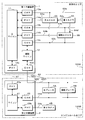
- FIG. 1 is a block diagram showing a configuration of an in-vehicle communication system according to the present embodiment.
- the in-vehicle communication system according to the present embodiment is a system in which a plurality of communication devices mounted on a vehicle having an automatic driving function communicate with each other. There are multiple places in the vehicle where these communication devices are installed.
- the vehicle interior area 100A includes, for example, a space on which a vehicle occupant is boarding and a space around the vehicle interior area 100A.
- the engine room area 100B is, for example, a space provided at the front of the vehicle and on which a prime mover such as an engine or a motor is mounted.
- the vehicle interior area 100A and the engine room area 100B are partitioned by, for example, a wall member or the like.
- a through hole is formed in the wall member. Electric wires such as communication lines and power lines are passed through the through holes, and electrical connections are made between the vehicle interior area 100A and the engine room area 100B via the electric wires.
- the vehicle interior area 100A is equipped with a first relay device 1, a main ADAS (Advanced Driver-Assistance Systems) 3A, an auxiliary ADAS 3B, a first camera 4A, and the like.
- the engine room area 100B is equipped with a second relay device 2, a second camera 4B, a main brake control device 5A, an auxiliary brake control device 5B, and the like.
- the "main brake control device” is abbreviated as “main brake”
- the "auxiliary brake control device” is abbreviated as "auxiliary brake”.
- These plurality of devices mounted on the vehicle are appropriately connected via communication lines such as a communication trunk line 61, an auxiliary communication line 62, a communication branch line 63a, 63b, 63c, 63d and a communication branch line 64a, 64b, 64c, 64d, 64e. It is connected and operates while exchanging information by communication.
- communication via the communication trunk line 61 and the communication branch lines 64a, 64b, 64c, 64d, 64e is performed according to the Ethernet communication standard.
- Communication via the auxiliary communication line 62 and the communication branch lines 63a, 63b, 63c, 63d is performed according to the CAN communication standard.
- the communication trunk line 61 and the auxiliary communication line 62 are communication lines arranged across the vehicle interior area 100A and the engine room area 100B of the vehicle through the through holes formed in the wall member serving as the above-mentioned partition.
- the communication trunk line 61 is a communication line that connects the first relay device 1 and the second relay device 2 on a one-to-one basis.
- the auxiliary communication line 62 includes a first auxiliary communication line 62a, an internal wiring 62b, and a second auxiliary communication line 62c.
- the first auxiliary communication line 62a connects the first relay device and the second relay device 2.
- the second auxiliary communication line 62c is a bus-type communication line that connects the second relay device 2, the main brake control device 5A, the auxiliary brake control device 5B, and the like.
- the internal wiring 62b is wiring provided inside the second relay device 2, and electrically connects the first auxiliary communication line 62a and the second auxiliary communication line 62c.
- the internal wiring 62b is, for example, a terminal to which the first auxiliary communication line 62a is connected, a terminal to which the second auxiliary communication line 62c is connected, a wiring pattern formed on a circuit board on which these terminals are mounted, or the like. is there.
- the communication branch line 63a is a bus-type communication line that connects the first relay device 1 and one or more devices including the main ADAS3A.
- the communication branch line 63b is a bus-type communication line that connects the first relay device 1 and one or more devices including the auxiliary ADAS3B.
- the communication branch line 63c is a bus-type communication line that connects the first relay device 1 and a plurality of devices including the main ADAS3A and the auxiliary ADAS3B.
- the communication branch line 63d is a bus-type communication line that connects the second relay device 2 and a plurality of devices including the main brake control device 5A and the auxiliary brake control device 5B.
- the communication branch line 64a is a communication line that connects the first relay device 1 and the main ADAS3A on a one-to-one basis.
- the communication branch line 64b is a communication line that connects the first relay device 1 and the auxiliary ADAS3B on a one-to-one basis.
- the communication branch line 64c is a communication line that connects the main ADAS3A and the first camera 4A on a one-to-one basis.
- the communication branch line 64d is a communication line that connects the auxiliary ADAS3B and the first camera 4A on a one-to-one basis.
- the communication branch line 64e is a communication line that connects the second relay device 2 and the second camera 4B on a one-to-one basis.
- Autonomous driving level 0 is a vehicle in which driving is not automated.
- Autonomous driving levels 1 to 3 are partially or limited autonomous driving and require the driver to be in the vehicle.
- Autonomous driving levels 4 and 5 are limited or fully autonomous driving, and the main body of driving is mechanical control, so that the driver does not need to board the vehicle.
- the vehicle according to the present embodiment may be one in which any of levels 1 to 5 is automatically driven.
- the main ADAS3A is a control device that controls driving related to automatic driving of the vehicle.
- the main ADAS3A operates the controlled devices such as the main brake control device 5A and the auxiliary brake control device 5B related to the running of the vehicle based on the information input from the input devices such as the first camera 4A and the second camera 4B. Control.
- the automatic driving of the vehicle is realized by the control of the main ADAS3A.
- the auxiliary ADAS3B controls the running of the vehicle on behalf of the main ADAS3A when a failure or malfunction of the main ADAS3A occurs.
- the auxiliary ADAS3B may be a device having the same configuration as the main ADAS3A, or may be a device having a different configuration.
- a device such as a body ECU of a vehicle may be configured to perform each process in a normal state and control the main ADAS3A in an emergency.
- the main ADAS3A and the auxiliary ADAS3B have the same configuration.
- the first camera 4A is mounted near the vehicle's room mirror, for example, and photographs the front of the vehicle.
- the first camera 4A is connected to the main ADAS3A via the communication branch line 64c, and is connected to the auxiliary ADAS3B via the communication branch line 64d.
- the first camera 4A inputs the data of the image in front of the vehicle acquired by photographing to the main ADAS3A and the auxiliary ADAS3B via the communication branch lines 64c and 64d, respectively.
- the second camera 4B is mounted on the front part of the vehicle body of the vehicle, for example, and photographs the front of the vehicle.
- the second camera 4B is connected to the second relay device 2 via a communication branch line 64e.
- the second camera 4B inputs the image data of the image in front of the vehicle acquired by photographing to the main ADAS3A and the auxiliary ADAS3B via the first relay device 1 and the second relay device 2, respectively.
- the devices for inputting information necessary for automatic driving of the vehicle are the first camera 4A and the second camera 4B, but the present invention is not limited to this.
- the input device may be, for example, a sensor that detects an object around the vehicle using ultrasonic waves, or various devices such as LiDAR (Light Detection And Ringing). Similar to the first camera 4A and the second camera 4B in the present embodiment, these input devices are preferably provided in both the vehicle interior area 100A and the engine room area 100B, respectively.
- the main brake control device 5A is a device that controls the brake of the vehicle.
- the main brake control device 5A activates the vehicle brake in response to a control command from the main ADAS3A or the auxiliary ADAS3B.
- the auxiliary brake control device 5B is a device that controls the brake of the vehicle in response to a control command of the main ADAS3A or the auxiliary ADAS3B, similarly to the main brake control device 5A.
- the auxiliary brake control device 5B controls the brake on behalf of the main brake control device 5A when a failure or malfunction of the main brake control device 5A occurs.
- the auxiliary brake control device 5B may have the same configuration as the main brake control device 5A, or may have a different configuration. In the present embodiment, the main brake control device 5A and the auxiliary brake control device 5B have the same configuration.
- the controlled devices controlled by the main ADAS3A and the auxiliary ADAS3B are the main brake control device 5A and the auxiliary brake control device 5B, but the present invention is not limited to this.
- the controlled device may be various devices such as a device for controlling a steering mechanism of a vehicle, a device for controlling an accelerator of a vehicle, and a device for controlling lighting such as a light of a vehicle.
- these controlled devices are preferably equipped with an auxiliary device that operates in an emergency, in addition to the device that operates in the normal state.
- the first relay device 1 includes a main microcomputer (microcontroller or microcomputer) 11, an auxiliary microcomputer 12, a plurality of CAN controllers 13a to 13d, and a plurality of Ethernet PHY (PHYsical layer) 14a to 14c.
- CAN controller is abbreviated as “CAN”
- Ethernet PHY is abbreviated as “PHY”.
- the first relay device 1 includes four CAN controllers 13a to 13d and three Ethernet PHYs 14a to 14c.
- the main microcomputer 11 is connected to two CAN controllers 13a and 13b and three Ethernet PHYs 14a to 14c.
- the main microcomputer 11 appropriately transmits a message received by any one of the CAN controllers 13a and 13b and the Ethernet PHYs 14a to 14c from the other CAN controllers 13a and 13b and the Ethernet PHYs 14a to 14c.
- the main microcomputer 11 performs a process of relaying the message.
- the CAN controller 13a is connected to the main ADAS3A and the like via the communication branch line 63a.
- the Ethernet PHY 14a is connected to the main ADAS3A via the communication branch line 64a.
- the Ethernet PHY 14c is connected to the second relay device 2 via the communication trunk line 61.
- the main microcomputer 11 transmits, for example, the image data of the second camera 4B received from the second relay device by the Ethernet PHY 14c to the main ADAS3A by the Ethernet PHY 14a.
- the main microcomputer 11 transmits a control command from the main ADAS3A received by the CAN controller 13a to the second relay device 2 via Ethernet PHY14c.
- the CAN controller 13b is connected to the auxiliary ADAS3B or the like via the communication branch line 63b.
- the Ethernet PHY 14b is connected to the auxiliary ADAS3B via the communication branch line 64b.
- the main microcomputer 11 transmits the image data of the second camera 4B received from the second relay device by the Ethernet PHY 14c to the auxiliary ADAS 3B by the Ethernet PHY 14b.
- the main microcomputer 11 transmits, for example, a control command from the auxiliary ADAS3B received by the CAN controller 13b to the second relay device 2 via Ethernet PHY14c.
- the main microcomputer 11 may relay the message regarding the auxiliary ADAS3B only when an abnormality or the like occurs in the main ADAS3A.
- the auxiliary microcomputer 12 relays the message by transmitting the message received by one CAN controller 13c, 13d from the other CAN controller 13c, 13d.
- the CAN controller 13c is connected to the main ADAS3A, the auxiliary ADAS3B, and the like via the communication branch line 63c.
- the CAN controller 13d is connected to the main brake control device 5A, the auxiliary brake control device 5B, and the like in the engine room area 100B via the auxiliary communication line 62.
- the auxiliary microcomputer 12 relays the communication between the main ADAS3A and the auxiliary ADAS3B and the main brake control device 5A and the auxiliary brake control device 5B.
- the message relay by the auxiliary microcomputer 12 may be performed only when the message relay by the main microcomputer 11 becomes impossible.
- the second relay device 2 is configured to include a microcomputer 21, a CAN controller 22, Ethernet PHY23a, 23b, and the like.
- the microcomputer 21 performs a process of relaying a message by appropriately transmitting a message received by any one of the CAN controller 22 and the Ethernet PHY 23a, 23b from the other CAN controller 22 and the Ethernet PHY 23a, 23b.
- the CAN controller 22 is connected to the main brake control device 5A, the auxiliary brake control device 5B, and the like via the communication branch line 63d.
- the Ethernet PHY 23a is connected to the first relay device 1 via the communication trunk line 61.
- the Ethernet PHY 23b is connected to the second camera 4B via the communication branch line 64e.
- the microcomputer 21 transmits, for example, the image data of the second camera 4B received by the Ethernet PHY 23b to the first relay device 1 by the Ethernet PHY 23a.
- the microcomputer 21 transmits a control command from the first relay device 1 received by the Ethernet PHY 23a to the main brake control device 5A or the auxiliary brake control device 5B by the CAN controller 22.
- the second relay device 2 includes a circuit board (not shown) on which a microcomputer 21, a CAN controller 22, Ethernet PHY23a, 23b, etc. are mounted.
- the circuit board is equipped with a connector to which the communication trunk line 61, the first auxiliary communication line 62a and the second auxiliary communication line 62c of the auxiliary communication line 62, the communication branch line 63d, and the communication branch line 64e are connected.
- the connector to which the first auxiliary communication line 62a is connected and the connector to which the second auxiliary communication line 62c is connected are electrically connected on the circuit board via the internal wiring 62b.
- the CAN controller 13d of the first relay device 1, the main brake control device 5A, the auxiliary brake control device 5B, and the like are electrically connected through the second relay device 2 and are electrically connected via the auxiliary communication line 62. Communication is possible.
- the internal wiring 62b of the circuit board may be provided with, for example, an amplifier circuit for amplifying a communication signal, a filter circuit for removing noise, or the like.
- a microcomputer 21, a CAN controller, or the like may intervene between the first auxiliary communication line 62a and the second auxiliary communication line 62c to perform relay processing.
- the vehicle is automatically brake-controlled by the control of the main brake control device 5A by the main ADAS3A in a normal state in which no abnormality or the like related to communication occurs.
- the main ADAS3A determines the situation in front of the vehicle based on the images in front of the vehicle obtained from the first camera 4A and the second camera 4B, and controls the braking operation. At this time, the image captured by the first camera 4A is directly input to the main ADAS3A via the communication branch line 64c.
- the images captured by the second camera 4B are the communication branch line 64e, the Ethernet PHY23b of the second relay device 2, the microcomputer 21, the Ethernet PHY23a, the communication trunk line 61, the Ethernet PHY14c of the first relay device 1, the main microcomputer 11, the Ethernet PHY14a, and communication. It is input to the main ADAS3A via the branch line 64a.
- the main ADAS3A transmits a control command for controlling the brake operation based on the input image data of the first camera 4A and the second camera 4B.
- the main ADAS3A does not require the image data of both the first camera 4A and the second camera 4B, and can control the brake operation based on the image data of either one.
- the brake control command by the main ADAS3A is the communication branch line 63a, the CAN controller 13a of the first relay device 1, the main microcomputer 11, the Ethernet PHY 14c, the communication trunk line 61, the Ethernet PHY 23a of the second relay device 2, the microcomputer 21, the CAN controller 22 and the like. It is given to the main brake control device 5A via the communication branch line 63d.
- the main brake control device 5A controls the operation of the vehicle brake in response to a given control command.
- the auxiliary ADAS3B controls the brake on behalf of the main ADAS3A.
- the image captured by the first camera 4A is directly input to the auxiliary ADAS3B via the communication branch line 64d.
- the images captured by the second camera 4B are the communication branch line 64e, the Ethernet PHY23b of the second relay device 2, the microcomputer 21, the Ethernet PHY23a, the communication trunk line 61, the Ethernet PHY14c of the first relay device 1, the main microcomputer 11, the Ethernet PHY14b, and communication. It is input to the auxiliary ADAS3B via the branch line 64b.
- the brake control command by the auxiliary ADAS3B is the communication branch line 63b, the CAN controller 13b of the first relay device 1, the main microcomputer 11, the Ethernet PHY 14c, the communication trunk line 61, the Ethernet PHY 23a of the second relay device 2, the microcomputer 21, the CAN controller 22 and the like. It is given to the main brake control device 5A via the communication branch line 63d.
- the auxiliary brake control device 5B controls the operation of the vehicle brake in place of the main brake control device 5A.
- the transmission / reception route of the control command from the main ADAS3A or the auxiliary ADAS3B to the auxiliary brake control device 5B is the same as the transmission / reception route of the control command from the main ADAS3A or the auxiliary ADAS3B to the main brake control device 5A.
- the first relay device 1 relays the communication by the auxiliary microcomputer 12 instead of the communication relay by the main microcomputer 11.
- the image data of the second camera 4B is not relayed via the auxiliary communication line 62, and the main ADAS3A controls based on the image data of the first camera 4A.
- the brake control command by the main ADAS3A is given to the main brake control device 5A via the communication branch line 63c, the CAN controller 13c, the auxiliary microcomputer 12, the CAN controller 13d, and the auxiliary communication line 62.
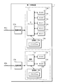
- FIG. 2 is a block diagram showing a configuration of the first relay device 1 according to the present embodiment.
- the first relay device 1 according to the present embodiment includes a main microcomputer 11, an auxiliary microcomputer 12, four CAN controllers 13a to 13d, three Ethernet PHYs 14a to 14c, two storage units (storage) 15a and 15b, and two power supplies. It is configured to include circuits 17a, 17b and the like.
- the main microcomputer 11 reads and executes the program 16a stored in the storage unit 15a to perform various processes related to message relay.
- the storage unit 15a is configured by using a non-volatile memory element such as a flash memory or an EEPROM (Electrically Erasable Programmable Read Only Memory).
- the storage unit 15a stores various programs executed by the main microcomputer 11 and various data required for processing of the main microcomputer 11.
- the auxiliary microcomputer 12 performs various processes related to message relay by reading and executing the program 16b stored in the storage unit 15b.
- the storage unit 15b is configured by using a non-volatile memory element such as a flash memory or EEPROM.
- the storage unit 15b stores various programs executed by the auxiliary microcomputer 12 and various data required for processing of the auxiliary microcomputer 12.
- the programs 16a and 16b may be written to the storage units 15a and 15b at the manufacturing stage of the first relay device 1, for example.
- the first relay device 1 may acquire what is distributed by a remote server device or the like by communication.
- a recording medium such as a memory card or an optical disk
- the writing device may read out what is recorded on the recording medium and write it in the storage units 15a and 15b of the first relay device 1.
- the programs 16a and 16b may be provided in a mode of distribution via a network, or may be provided in a mode recorded on a recording medium.
- the CAN controllers 13a to 13d send and receive messages according to the CAN communication protocol via the connected communication line.
- Each of the CAN controllers 13a to 13d can be configured as, for example, one IC.
- the CAN controllers 13a and 13b transmit a message to another device by converting a message for transmission given from the main microcomputer 11 into an electric signal corresponding to the communication standard of CAN and outputting it to a communication line.
- the CAN controllers 13a and 13b receive a message from another device by sampling and acquiring the potential of the communication line, and give the received message to the main microcomputer 11.
- the CAN controllers 13c and 13d convert the message for transmission given from the auxiliary microcomputer 12 into an electric signal corresponding to the communication standard of CAN and output the message to the communication line to transmit the message to other devices. I do.
- the CAN controllers 13b and 13c receive a message from another device by sampling and acquiring the potential of the communication line, and give the received message to the auxiliary microcomputer 12.
- Ethernet PHY14a to 14c transmit and receive messages according to the Ethernet communication protocol via the connected communication line.
- the Ethernet PHYs 14a to 14c can be configured as, for example, one IC each.
- the Ethernet PHYs 14a to 14c transmit a message to another device by converting a transmission message given from the main microcomputer 11 into an electric signal corresponding to the Ethernet communication standard and outputting it to a communication line.
- the Ethernet PHYs 14a to 14c receive a message from another device by sampling and acquiring the potential of the communication line, and give the received message to the main microcomputer 11.
- the power supply circuits 17a and 17b are connected to batteries mounted on the vehicle (not shown) via power lines 65a and 65b, respectively.
- the power supply circuits 17a and 17b convert, for example, 12V power supplied from a battery into electric power such as 5V or 3V.
- the power supply circuit 17a supplies electric power to the main microcomputer 11, the CAN controllers 13a and 13b, the Ethernet PHYs 14a to 14c, the storage unit 15a, and the like.
- the power supply circuit 17b supplies electric power to the auxiliary microcomputer 12, the CAN controllers 13c and 13d, the storage unit 15b, and the like.
- FIG. 3 is a block diagram showing the configuration of the second relay device 2 according to the present embodiment.
- the second relay device 2 includes a microcomputer 21, a CAN controller 22, two Ethernet PHYs 23a and 23b, a storage unit (storage) 24, a power supply circuit 26, an internal wiring 62b, and the like.
- the microcomputer 21 reads and executes the program 25 stored in the storage unit 24 to perform various processes related to message relay.
- the storage unit 24 is configured by using a non-volatile memory element such as a flash memory or EEPROM.
- the storage unit 24 stores various programs executed by the microcomputer 21 and various data required for processing of the microcomputer 21.
- the program 25 may be written in the storage unit 24, for example, at the manufacturing stage of the second relay device 2.
- the second relay device 2 may acquire what is distributed by a remote server device or the like by communication.
- a recording medium such as a memory card or an optical disk
- the program 25 may be read by the writing device and written in the storage unit 24 of the second relay device 2.
- the program 25 may be provided in a mode of distribution via a network, or may be provided in a mode recorded on a recording medium.
- the CAN controller 22 sends and receives messages according to the CAN communication protocol via the connected communication line.
- the CAN controller 22 can be configured as, for example, one IC.
- the CAN controller 22 transmits a message to another device by converting a message for transmission given from the microcomputer 21 into an electric signal corresponding to the communication standard of CAN and outputting it to a communication line.
- the CAN controller 22b receives a message from another device by sampling and acquiring the potential of the communication line, and gives the received message to the microcomputer 21.
- Ethernet PHY23a and 23b transmit and receive messages according to the Ethernet communication protocol via the connected communication line.
- the Ethernet PHYs 23a and 23b can be configured as, for example, one IC each.
- the Ethernet PHYs 23a and 23b transmit a message to another device by converting a transmission message given from the microcomputer 21 into an electric signal corresponding to the Ethernet communication standard and outputting the message to the communication line.
- the Ethernet PHYs 23a and 23b receive a message from another device by sampling and acquiring the potential of the communication line, and give the received message to the microcomputer 21.
- the power supply circuit 26 is connected to the battery mounted on the vehicle via the power line 65c.
- the power supply circuit 26 converts, for example, the 12V power supplied from the battery into a power such as 5V or 3V.
- the power supply circuit 26 supplies electric power to the microcomputer 21, the CAN controller 22, the Ethernet PHYs 23a and 23b, the storage unit 24, and the like.
- the internal wiring 62b can be provided as a hein pattern on a circuit board on which, for example, a microcomputer 21, a CAN controller 23, Ethernet PHY23a, 23b, a storage unit 24, and a power supply circuit 26 are mounted.
- the second relay device 2 includes a terminal to which the first auxiliary communication line 62a of the auxiliary communication line 62 is connected and a terminal to which the second auxiliary communication line 62c is connected.
- the internal wiring 62b is a wiring pattern that electrically connects the two terminals.
- FIG. 4 is a block diagram showing the configuration of the main ADAS3A according to the present embodiment. Since the configuration of the auxiliary ADAS3B according to the present embodiment is the same as the configuration of the main ADAS3A, the illustration and description of the block diagram will be omitted.
- the main ADAS3A according to the present embodiment is configured to include a processing unit (processor) 31, a storage unit (storage) 32, two CAN controllers 33a and 33b, and two Ethernet PHYs 34a and 34b.
- the processing unit 31 is configured by using an arithmetic processing unit such as a CPU (Central Processing Unit) or an MPU (Micro-Processing Unit). By reading and executing the program 32a stored in the storage unit 32, the processing unit 31 performs various processes such as traveling control related to automatic driving of the vehicle and switching control between automatic driving and manual driving.
- CPU Central Processing Unit
- MPU Micro-Processing Unit
- the storage unit 32 is configured by using a non-volatile memory element such as a flash memory or EEPROM.
- the storage unit 32 stores various programs executed by the processing unit 31 and various data required for processing by the processing unit 31.
- the program 32a may be written to the storage unit 32, for example, at the manufacturing stage of the main ADAS3A.
- the main ADAS3A may acquire what is distributed by a remote server device or the like by communication.
- a recording medium such as a memory card or an optical disk may be read by the main ADAS3A and stored in the storage unit 32.
- the writing device may read what has been recorded on the recording medium and write it in the storage unit 32 of the main ADAS3A.
- the program 32a may be provided in a mode of distribution via a network, or may be provided in a mode recorded on a recording medium.
- the CAN controllers 33a and 33b send and receive messages according to the CAN communication protocol via the connected communication line.
- the CAN controllers 33a and 33b can be configured as one IC, for example.
- the CAN controllers 33a and 33b convert the message for transmission given from the processing unit 31 into an electric signal corresponding to the communication standard of CAN and output it to the communication line to transmit the message to another device.
- the CAN controllers 33a and 33b receive a message from another device by sampling and acquiring the potential of the communication line, and give the received message to the processing unit 31.
- the Ethernet PHYs 34a and 34b send and receive messages according to the Ethernet communication protocol via the connected communication line.
- the Ethernet PHYs 34a and 34b can be configured as, for example, one IC each.
- the Ethernet PHYs 34a and 34b transmit a message to another device by converting a transmission message given from the processing unit 31 into an electric signal corresponding to the Ethernet communication standard and outputting the message to the communication line.
- the Ethernet PHYs 34a and 34b receive a message from another device by sampling and acquiring the potential of the communication line, and give the received message to the processing unit 31.
- the processing unit 31 reads out and executes the program 32a stored in the storage unit 32, so that the traveling control unit 31a, the switching control unit 31b, and the like function as software in the processing unit 31.
- the travel control unit 31a controls the operation of the main brake control device 5A, the auxiliary brake control device 5B, and the like based on the information input from the input devices such as the first camera 4A and the second camera 4B, thereby controlling the operation of the vehicle.
- Vehicle travel control may include, for example, control of vehicle acceleration, deceleration, stopping, left and right steering operations, turning on and off of turn signals and headlights, or wiper operation. The details of the traveling control of the vehicle will be omitted.
- the switching control unit 31b performs a process of switching between manual driving and automatic driving of the vehicle, for example, in response to a user operation on a switch provided in the vehicle interior of the vehicle.
- the switching control unit 31b determines whether or not both the communication path via the communication trunk line 61 and the communication path via the auxiliary communication line 62 can communicate with each other. To do.
- both communication paths are communicable, the switching control unit 31b switches from manual operation to automatic operation.
- the switching control unit 31b does not switch from the manual operation to the automatic operation, and displays a warning message or the like.
- the switching control unit 31b determines, for example, whether or not the driver is present in the driver's seat of the vehicle, whether or not the driver is in a driving state, and the like. Whether or not switching is possible is determined based on this.
- ⁇ Communication path switching process> there are two communication paths for transmitting and receiving messages between the vehicle interior area 100A and the engine room area 100B of the vehicle.
- One is a communication path via the communication trunk line 61
- the other is a communication path via the auxiliary communication line 62.
- a message is transmitted and received between the vehicle interior area 100A and the engine room area 100B by using the communication path via the communication trunk line 61 in a normal state in which no abnormality or the like related to communication occurs.
- a message is transmitted / received between the vehicle interior area 100A and the engine room area 100B by using the communication path via the auxiliary communication line 62.
- Switching from message transmission / reception using the communication path via the communication trunk line 61 to message transmission / reception using the communication path via the auxiliary communication line 62 may be performed under the initiative of any device included in the in-vehicle communication system.
- the first relay device 1 performs the switching of the communication path and a case where the ADAS performs the switching will be described.
- the auxiliary microcomputer 12 of the first relay device 1 periodically checks the operating status of the main microcomputer 11 and determines whether or not there is an abnormality in the main microcomputer 11. ..
- the auxiliary microcomputer 12 determines that an abnormality has occurred in the main microcomputer 11
- the auxiliary microcomputer 12 stops the main microcomputer 11.
- the auxiliary microcomputer 12 starts relaying a message between the communication branch line 63c connected to the CAN controller 13c and the auxiliary communication line 62 connected to the CAN controller 13d.
- the main microcomputer 11 may transmit a message notifying that the communication path is switched from the CAN controllers 13c and 13d.
- the devices such as the main ADAS3A and the auxiliary ADAS3B connected to the communication branch line 63c and the devices such as the main brake control device 5A and the auxiliary brake control device 5B connected to the auxiliary communication line 62 are messages. Switch the communication path to send and receive.
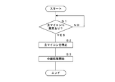
- FIG. 5 is a flowchart showing a procedure of communication path switching processing performed by the first relay device 1 according to the present embodiment.
- the auxiliary microcomputer 12 of the first relay device 1 according to the present embodiment determines the presence or absence of an abnormality in the main microcomputer 11 (step S1). If there is no abnormality (S1: NO), the auxiliary microcomputer 12 waits until an abnormality occurs in the main microcomputer 11. If there is an abnormality (S1: YES), the auxiliary microcomputer 12 stops the operation of the main microcomputer 11 (step S2). Next, the auxiliary microcomputer 12 starts the relay processing of the message received by the CAN controllers 13c and 13d (step S3), and ends the switching processing.
- the processing unit 31 of the main ADAS3A determines whether or not there is an abnormality in the communication route via the communication trunk line 61.
- the processing unit 31 receives a message from the second camera 4B, the main brake control device 5A, the auxiliary brake control device 5B, etc. mounted on the engine room area 100B of the vehicle by communication via, for example, the communication branch line 63a or the communication branch line 64a. Check for presence. If the message is not received for a predetermined period of time, the processing unit 31 can determine that an abnormality has occurred in the communication path via the communication trunk line 61.
- the processing unit 31 stops the communication using the communication path via the communication trunk line 61, and starts the communication using the communication path via the auxiliary communication line 62. At this time, the processing unit 31 may send a message instructing the switching of the communication path to one or more devices connected to the communication path via the auxiliary communication line 62.
- the auxiliary ADAS3B performs the same communication path switching process.
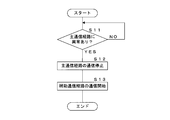
- FIG. 6 is a flowchart showing the procedure of the communication path switching process performed by the main ADAS3A according to the present embodiment.
- the communication path via the communication trunk line 61 is abbreviated as “main communication path”
- the communication path via the auxiliary communication line 62 is abbreviated as "auxiliary communication path”.
- the processing unit 31 of the main ADAS3A according to the present embodiment determines whether or not there is an abnormality in the communication path via the communication trunk line 61 (step S11). When it is determined that there is no abnormality (S11: NO), the processing unit 31 waits until an abnormality occurs without switching the communication path.
- the processing unit 31 stops the communication using the communication path via the communication trunk line 61 (step S12). Next, the processing unit 31 starts communication using the communication path via the auxiliary communication line 62 (step S13), and ends the switching process.
- ⁇ Switching process from manual operation to automatic operation> for example, switching from manual driving to automatic driving of the vehicle is performed in response to a user operation on a switch or the like provided in the vehicle interior of the vehicle.
- the main ADAS3A checks for abnormalities in the devices and systems related to automatic driving mounted on the vehicle.
- the main ADAS3A switches to automatic operation when it is determined that there is no abnormality.
- the main ADAS3A determines that there is an abnormality, it does not switch to automatic driving, and displays, for example, a warning message or the like notifying that an abnormality has occurred in automatic driving on a display or the like in the vehicle interior.
- the main ADAS3A includes communication using a communication path via the communication trunk line 61 and communication using a communication path via the auxiliary communication line 62 when switching from manual operation to automatic operation is requested. Judge the presence or absence of abnormality. When there is no abnormality in both communication paths, the main ADAS3A switches from manual operation to automatic operation, and the main brake control device 5A and the auxiliary are based on the information input from the first camera 4A, the second camera 4B, and the like. Control of the brake control device 5B and the like is started. When there is an abnormality in one of the communication paths, the main ADAS3A displays a warning message without switching from manual operation to automatic operation.
- a device such as a display for displaying a warning message is mounted on, for example, the vehicle interior area 100A of the vehicle, and is connected to the main ADAS3A or the first relay device 1 via a communication branch line.
- the main ADAS3A can display a warning message by communicating with a device such as a display via a communication branch line and the first relay device 1.
- FIG. 7 is a flowchart showing a procedure of switching processing from manual operation to automatic operation performed by the main ADAS3A according to the present embodiment.
- the communication path via the communication trunk line 61 is abbreviated as “main communication path”
- the communication path via the auxiliary communication line 62 is abbreviated as “auxiliary communication path”.
- the switching control unit 31b of the processing unit 31 of the main ADAS3A according to the present embodiment determines whether or not a request for switching from manual operation to automatic operation based on user operation has been given (step S21). When the switching request is not given (S21: NO), the switching control unit 31b maintains the manual operation and waits until the switching request is given.
- the switching control unit 31b confirms the operation of the communication path via the communication trunk line 61 (step S22). At this time, the switching control unit 31b confirms the operation of the second relay device 2, the main brake control device 5A, the auxiliary brake control device 5B, the second camera 4B, etc. by using the communication path via the communication trunk line 61, for example. Send a message. The switching control unit 31b can confirm the operation depending on whether or not there is a response to this message. Next, the switching control unit 31b confirms the operation of the communication path via the auxiliary communication line 62 (step S23).
- the switching control unit 31b transmits an operation confirmation message to the main brake control device 5A, the auxiliary brake control device 5B, and the like by using, for example, a communication path via the auxiliary communication line 62, and responds to this message.
- the operation can be confirmed by receiving.
- the switching control unit 31b determines whether or not communication is possible for both the communication path via the communication trunk line 61 and the communication path via the auxiliary communication line 62 ( Step S24).
- the switching control unit 31b switches from manual operation to automatic operation (step S25), and ends the process.
- the switching control unit 31b notifies an abnormality by displaying a warning message on the display (step S26), and ends the process. ..
- the area inside the vehicle on which various devices can be mounted is divided into at least two of the vehicle interior area 100A and the engine room area 100B.
- the vehicle interior area 100A is equipped with a main ADAS3A and an auxiliary ADAS3B for controlling the traveling of the vehicle, a first relay device 1 for relaying communication, and a first camera 4A for inputting information used for traveling control.
- the main brake control device 5A and the auxiliary brake control device 5B controlled by the main ADAS3A and the auxiliary ADAS3B, the second relay device 2 for relaying communication, and the second relay device 2 for inputting information used for driving control are input.
- a camera 4B is installed.
- the first relay device 1 and the second relay device 2 are connected via a communication trunk line 61 that straddles the two areas.
- the first relay device 1, the main brake control device 5A, and the auxiliary brake control device 5B are connected via an auxiliary communication line 62 straddling the two areas.
- the main ADAS3A and the auxiliary ADAS3B provided in the vehicle interior area 100A communicate with the main brake control device 5A and the auxiliary brake control device 5B provided in the engine room area 100B by using two communication paths. It becomes possible to do.
- the main ADAS3A and the auxiliary ADAS3B communicate with the main brake control device 5A and the auxiliary brake control device 5B by using the other communication path even if a problem occurs in one of the communication paths. be able to. Therefore, it is possible to improve the trust line related to the communication of the in-vehicle communication system.
- two control devices a main ADAS3A and an auxiliary ADAS3B
- the other control device can control the main brake control device 5A and the auxiliary brake control device 5B.
- the first camera 4A is mounted in the vehicle interior area 100A
- the second camera 4B is mounted in the engine room area 100B.
- the other camera can input information to the main ADAS3A and the auxiliary ADAS3B.
- two brake control devices a main brake control device 5A and an auxiliary brake control device 5B, are mounted on the vehicle.
- the main ADAS3A and the auxiliary ADAS3B can control the operation of the other brake control device and control the brake of the vehicle.
- auxiliary communication lines 62 connecting the main ADAS3A and the auxiliary ADAS3B in the vehicle interior area 100A and the main brake control device 5A and the auxiliary brake control device 5B in the engine room area 100B. It is provided separately.
- the auxiliary communication line 62 includes a first auxiliary communication line 62a, an internal wiring 62b, and a second auxiliary communication line 62c.
- the first auxiliary communication line 62a is a communication line connecting the first relay device 1 and the second relay device 2.
- the second auxiliary communication line 62c is a communication line connecting the second relay device 2, the main brake control device 5A, and the auxiliary brake control device 5B.
- the internal wiring 62b is wiring in the second relay device 2 that electrically connects the first auxiliary communication line 62a and the second auxiliary communication line 62c.
- the communication trunk line 61 and the auxiliary communication line 62 provided across the vehicle interior area 100A and the engine room area 100B of the vehicle are both connected to the first relay device 1 and the second relay device 2.
- the wire connection work can be facilitated.
- the communication trunk line 61 is a communication line that connects the first relay device 1 and the second relay device 2 on a one-to-one basis.
- the communication trunk line 61 is, for example, a communication line that complies with the Ethernet communication standard.
- the auxiliary communication line 62 is a bus-type communication line that connects the first relay device 1 with a plurality of devices such as the main brake control device 5A and the auxiliary brake control device 5B.
- the auxiliary communication line 62 is, for example, a communication line that conforms to the communication standard of CAN.
- the communication trunk line 61 according to the Ethernet communication standard is a communication line capable of high-speed communication of, for example, 100 Mbps
- the auxiliary communication line 62 according to the CAN communication standard is a communication line capable of low-speed communication of, for example, 1 Mbps.
- the first relay device 1 includes two microcomputers, a main microcomputer 11 and an auxiliary microcomputer 12, and two power supply circuits 17a and 17b.
- the main microcomputer 11 performs a process of relaying communication between the main ADAS3A and the auxiliary ADAS3B and the second relay device 2 via the communication trunk line 61.
- the auxiliary microcomputer 12 performs a process of relaying communication between the main ADAS3A and the auxiliary ADAS3B and the main brake control device 5A and the auxiliary brake control device 5B via the auxiliary communication line 62.
- One power supply circuit 17a supplies electric power to the main microcomputer 11.
- the other power supply circuit 17b supplies power to the auxiliary microcomputer 12.
- the auxiliary microcomputer 12 determines whether or not there is an abnormality related to the processing of the main microcomputer 11. When it is determined that there is an abnormality, the auxiliary microcomputer 12 relays the message via the auxiliary communication line 62. As a result, the first relay device 1 can switch between communication via the communication trunk line 61 and communication via the auxiliary communication line 62.
- the vehicle is equipped with an automatic driving function, and the occupant of the vehicle can switch between manual driving and automatic driving.
- the main ADAS3A and the auxiliary ADAS3B perform traveling control related to the automatic driving of the vehicle.
- the main ADAS3A and the auxiliary ADAS3B determine whether or not the communication by the communication trunk line 61 and the auxiliary communication line 62 is possible.
- the main ADAS3A and the auxiliary ADAS3B switch to automatic operation when communication is possible for both the communication trunk line 61 and the auxiliary communication line 62.
- the main ADAS3A and the auxiliary ADAS3B do not switch to automatic operation when communication is not possible for at least one of the communication trunk line 61 and the auxiliary communication line 62. As a result, it is possible to prevent switching from manual operation to automatic operation in a state where the reliability of communication is lowered.
- the device for inputting information to the main ADAS3A and the auxiliary ADAS3B is a camera, but the present invention is not limited to this.
- the input device may be various devices such as an ultrasonic sensor or LiDAR.
- the controlled devices controlled by the main ADAS3A and the auxiliary ADAS3B are the main brake control device 5A and the auxiliary brake control device 5B, but the present invention is not limited to this.
- the controlled device may be various devices such as a steering wheel, an accelerator, an indicator, a light and a wiper.
- the control device for controlling the running of the vehicle is ADAS, but the present invention is not limited to this.
- the control device may be various devices other than ADAS.
- the area in which the device can be mounted in the vehicle is divided into two areas, the vehicle interior area 100A and the engine room area 100B, but the present invention is not limited to this.
- the mounting area of the device may be divided into three or more, and a communication trunk line and an auxiliary communication line are provided for communication across the two areas.
- the arrangement of the devices and the connection of communication lines shown in FIG. 1 are examples, and are not limited thereto.
- the number of CAN controllers mounted and the number of Ethernet PHYs mounted are examples, and are not limited thereto.
- the communication trunk line 61 is a communication line conforming to the Ethernet communication standard
- the auxiliary communication line 62 is a communication line conforming to the CAN communication standard, but the present invention is not limited to this.
- both the communication trunk line 61 and the auxiliary communication line 62 may be communication lines that comply with the Ethernet communication standard.
- Both the communication trunk line 61 and the auxiliary communication line 62 may be communication lines that comply with the CAN communication standard.
- the communication trunk line 61 and the auxiliary communication line 62 may be communication powers that comply with communication standards different from Ethernet and CAN.
- the communication standard can be selected as appropriate.
- Each device in the in-vehicle communication system includes a computer including a microprocessor, ROM, RAM, and the like.
- An arithmetic processing unit such as a microprocessor reads a computer program including a part or all of each step of a sequence diagram or a flowchart as shown in FIGS. 5 to 7 from a storage unit such as a ROM or RAM and executes the program. You can.
- the computer programs of these plurality of devices can be installed from an external server device or the like. Further, the computer programs of these plurality of devices are distributed in a state of being stored in a recording medium such as a CD-ROM, a DVD-ROM, or a semiconductor memory, respectively.
Landscapes
- Engineering & Computer Science (AREA)
- Automation & Control Theory (AREA)
- Mechanical Engineering (AREA)
- Computer Networks & Wireless Communication (AREA)
- Signal Processing (AREA)
- Human Computer Interaction (AREA)
- Transportation (AREA)
- Small-Scale Networks (AREA)
- Cable Transmission Systems, Equalization Of Radio And Reduction Of Echo (AREA)
Priority Applications (2)
| Application Number | Priority Date | Filing Date | Title |
|---|---|---|---|
| CN202080024695.0A CN113632424B (zh) | 2019-03-27 | 2020-01-22 | 车载通信系统,车载中继装置及车载控制装置 |
| US17/442,942 US11697423B2 (en) | 2019-03-27 | 2020-01-22 | In-vehicle communication system, in-vehicle relay apparatus, and in-vehicle control apparatus |
Applications Claiming Priority (2)
| Application Number | Priority Date | Filing Date | Title |
|---|---|---|---|
| JP2019060936A JP7230636B2 (ja) | 2019-03-27 | 2019-03-27 | 車載通信システム及び車載中継装置 |
| JP2019-060936 | 2019-03-27 |
Publications (1)
| Publication Number | Publication Date |
|---|---|
| WO2020195066A1 true WO2020195066A1 (ja) | 2020-10-01 |
Family
ID=72611774
Family Applications (1)
| Application Number | Title | Priority Date | Filing Date |
|---|---|---|---|
| PCT/JP2020/002145 Ceased WO2020195066A1 (ja) | 2019-03-27 | 2020-01-22 | 車載通信システム、車載中継装置及び車載制御装置 |
Country Status (4)
| Country | Link |
|---|---|
| US (1) | US11697423B2 (https=) |
| JP (1) | JP7230636B2 (https=) |
| CN (1) | CN113632424B (https=) |
| WO (1) | WO2020195066A1 (https=) |
Cited By (1)
| Publication number | Priority date | Publication date | Assignee | Title |
|---|---|---|---|---|
| CN115460044A (zh) * | 2022-08-31 | 2022-12-09 | 重庆长安汽车股份有限公司 | 基于soc芯片的车载网关、控制方法及车载装置 |
Families Citing this family (4)
| Publication number | Priority date | Publication date | Assignee | Title |
|---|---|---|---|---|
| JP2021145162A (ja) * | 2020-03-10 | 2021-09-24 | 本田技研工業株式会社 | 通信制御システム |
| US12160279B2 (en) * | 2020-11-25 | 2024-12-03 | Marvell Asia Pte Ltd | Automotive physical layer (PHY) cable fault diagnosis |
| JP7472842B2 (ja) * | 2021-04-02 | 2024-04-23 | トヨタ自動車株式会社 | 車両の制御装置 |
| US20240380668A1 (en) * | 2023-05-08 | 2024-11-14 | Analog Devices International Unlimited Company | Operating a network node |
Citations (5)
| Publication number | Priority date | Publication date | Assignee | Title |
|---|---|---|---|---|
| JP2009262609A (ja) * | 2008-04-22 | 2009-11-12 | Nissan Motor Co Ltd | 車両用操舵装置 |
| JP2014118072A (ja) * | 2012-12-18 | 2014-06-30 | Honda Motor Co Ltd | 車両制御システム |
| JP2015067187A (ja) * | 2013-09-30 | 2015-04-13 | 株式会社デンソー | 車両制御システム |
| JP2017074887A (ja) * | 2015-10-16 | 2017-04-20 | 日立オートモティブシステムズ株式会社 | 自動運転システム、自動運転制御方法、データecuおよび自動運転ecu |
| WO2019004173A1 (ja) * | 2017-06-26 | 2019-01-03 | 株式会社オートネットワーク技術研究所 | 車載通信システム、車載中継装置及び中継プログラム |
Family Cites Families (4)
| Publication number | Priority date | Publication date | Assignee | Title |
|---|---|---|---|---|
| WO2011142113A1 (ja) * | 2010-05-10 | 2011-11-17 | パナソニック株式会社 | デジタル放送受信装置及びデジタル放送受信方法 |
| FR3047274B1 (fr) * | 2016-01-29 | 2018-01-26 | Safran Power Units | Systeme de regulation electronique partiellement redondant |
| US11126176B2 (en) * | 2016-08-10 | 2021-09-21 | Hitachi Automottve Systems, Ltd. | Vehicle control apparatus |
| JP6485429B2 (ja) * | 2016-11-04 | 2019-03-20 | トヨタ自動車株式会社 | 車載ネットワークシステム |
-
2019
- 2019-03-27 JP JP2019060936A patent/JP7230636B2/ja active Active
-
2020
- 2020-01-22 WO PCT/JP2020/002145 patent/WO2020195066A1/ja not_active Ceased
- 2020-01-22 US US17/442,942 patent/US11697423B2/en active Active
- 2020-01-22 CN CN202080024695.0A patent/CN113632424B/zh active Active
Patent Citations (5)
| Publication number | Priority date | Publication date | Assignee | Title |
|---|---|---|---|---|
| JP2009262609A (ja) * | 2008-04-22 | 2009-11-12 | Nissan Motor Co Ltd | 車両用操舵装置 |
| JP2014118072A (ja) * | 2012-12-18 | 2014-06-30 | Honda Motor Co Ltd | 車両制御システム |
| JP2015067187A (ja) * | 2013-09-30 | 2015-04-13 | 株式会社デンソー | 車両制御システム |
| JP2017074887A (ja) * | 2015-10-16 | 2017-04-20 | 日立オートモティブシステムズ株式会社 | 自動運転システム、自動運転制御方法、データecuおよび自動運転ecu |
| WO2019004173A1 (ja) * | 2017-06-26 | 2019-01-03 | 株式会社オートネットワーク技術研究所 | 車載通信システム、車載中継装置及び中継プログラム |
Cited By (2)
| Publication number | Priority date | Publication date | Assignee | Title |
|---|---|---|---|---|
| CN115460044A (zh) * | 2022-08-31 | 2022-12-09 | 重庆长安汽车股份有限公司 | 基于soc芯片的车载网关、控制方法及车载装置 |
| CN115460044B (zh) * | 2022-08-31 | 2023-06-06 | 重庆长安汽车股份有限公司 | 基于soc芯片的车载网关、控制方法及车载装置 |
Also Published As
| Publication number | Publication date |
|---|---|
| CN113632424B (zh) | 2023-02-14 |
| CN113632424A (zh) | 2021-11-09 |
| US11697423B2 (en) | 2023-07-11 |
| JP7230636B2 (ja) | 2023-03-01 |
| US20220126846A1 (en) | 2022-04-28 |
| JP2020157994A (ja) | 2020-10-01 |
Similar Documents
| Publication | Publication Date | Title |
|---|---|---|
| WO2020195066A1 (ja) | 車載通信システム、車載中継装置及び車載制御装置 | |
| CN112429012B (zh) | 汽车电控系统、自动驾驶控制方法及汽车 | |
| CN114726782A (zh) | 车内通信系统、车内通信的方法及设备 | |
| JP6460080B2 (ja) | 車載ネットワークシステム | |
| WO1993004896A1 (fr) | Unite de regroupement de modules de commande pour etre montee sur un vehicule | |
| CN111971934A (zh) | 网关装置 | |
| CN114954306A (zh) | 一种商用车的模块化电子电气架构 | |
| CN117615939A (zh) | 车辆系统 | |
| US11970121B2 (en) | In-vehicle power supply system | |
| CN112449321B (zh) | 车载网络系统 | |
| CN112448997B (zh) | 车载网络系统 | |
| US20240217458A1 (en) | Vehicle mounted communication apparatus and vehicle mounted communication system | |
| JP7540353B2 (ja) | 車載装置、及び情報処理方法 | |
| US20160225196A1 (en) | Electronic control device and electronic control system | |
| US12447917B2 (en) | Vehicle system | |
| JP5359449B2 (ja) | 中継システム及び制御装置 | |
| EP3998178A1 (en) | In-vehicle power supply system | |
| JP7852737B2 (ja) | 車載通信システムおよび制御装置 | |
| JP7513126B2 (ja) | 車載装置、及び中継方法 | |
| JP2021103825A (ja) | 車載中継装置 | |
| JP2023172726A (ja) | 車載装置 | |
| JP2025146351A (ja) | ジョイントコネクタ | |
| WO2024089949A1 (ja) | 車載通信システム、制御装置および電気装置 | |
| CN118306354A (zh) | 车辆的制动系统及其刷写方法 | |
| JP2014151857A (ja) | 車両用電装システム及び車両用電装システムの不具合検出方法 |
Legal Events
| Date | Code | Title | Description |
|---|---|---|---|
| 121 | Ep: the epo has been informed by wipo that ep was designated in this application |
Ref document number: 20779796 Country of ref document: EP Kind code of ref document: A1 |
|
| NENP | Non-entry into the national phase |
Ref country code: DE |
|
| 122 | Ep: pct application non-entry in european phase |
Ref document number: 20779796 Country of ref document: EP Kind code of ref document: A1 |