WO2020195066A1 - 車載通信システム、車載中継装置及び車載制御装置 - Google Patents
車載通信システム、車載中継装置及び車載制御装置 Download PDFInfo
- Publication number
- WO2020195066A1 WO2020195066A1 PCT/JP2020/002145 JP2020002145W WO2020195066A1 WO 2020195066 A1 WO2020195066 A1 WO 2020195066A1 JP 2020002145 W JP2020002145 W JP 2020002145W WO 2020195066 A1 WO2020195066 A1 WO 2020195066A1
- Authority
- WO
- WIPO (PCT)
- Prior art keywords
- communication
- auxiliary
- control device
- vehicle
- main
- Prior art date
Links
Images


Classifications
-
- B—PERFORMING OPERATIONS; TRANSPORTING
- B60—VEHICLES IN GENERAL
- B60W—CONJOINT CONTROL OF VEHICLE SUB-UNITS OF DIFFERENT TYPE OR DIFFERENT FUNCTION; CONTROL SYSTEMS SPECIALLY ADAPTED FOR HYBRID VEHICLES; ROAD VEHICLE DRIVE CONTROL SYSTEMS FOR PURPOSES NOT RELATED TO THE CONTROL OF A PARTICULAR SUB-UNIT
- B60W50/00—Details of control systems for road vehicle drive control not related to the control of a particular sub-unit, e.g. process diagnostic or vehicle driver interfaces
- B60W50/02—Ensuring safety in case of control system failures, e.g. by diagnosing, circumventing or fixing failures
- B60W50/023—Avoiding failures by using redundant parts
-
- H—ELECTRICITY
- H04—ELECTRIC COMMUNICATION TECHNIQUE
- H04L—TRANSMISSION OF DIGITAL INFORMATION, e.g. TELEGRAPHIC COMMUNICATION
- H04L12/00—Data switching networks
- H04L12/28—Data switching networks characterised by path configuration, e.g. LAN [Local Area Networks] or WAN [Wide Area Networks]
- H04L12/40—Bus networks
- H04L12/40169—Flexible bus arrangements
- H04L12/40176—Flexible bus arrangements involving redundancy
- H04L12/40189—Flexible bus arrangements involving redundancy by using a plurality of bus systems
-
- B—PERFORMING OPERATIONS; TRANSPORTING
- B60—VEHICLES IN GENERAL
- B60R—VEHICLES, VEHICLE FITTINGS, OR VEHICLE PARTS, NOT OTHERWISE PROVIDED FOR
- B60R16/00—Electric or fluid circuits specially adapted for vehicles and not otherwise provided for; Arrangement of elements of electric or fluid circuits specially adapted for vehicles and not otherwise provided for
- B60R16/02—Electric or fluid circuits specially adapted for vehicles and not otherwise provided for; Arrangement of elements of electric or fluid circuits specially adapted for vehicles and not otherwise provided for electric constitutive elements
- B60R16/023—Electric or fluid circuits specially adapted for vehicles and not otherwise provided for; Arrangement of elements of electric or fluid circuits specially adapted for vehicles and not otherwise provided for electric constitutive elements for transmission of signals between vehicle parts or subsystems
- B60R16/0231—Circuits relating to the driving or the functioning of the vehicle
-
- B—PERFORMING OPERATIONS; TRANSPORTING
- B60—VEHICLES IN GENERAL
- B60W—CONJOINT CONTROL OF VEHICLE SUB-UNITS OF DIFFERENT TYPE OR DIFFERENT FUNCTION; CONTROL SYSTEMS SPECIALLY ADAPTED FOR HYBRID VEHICLES; ROAD VEHICLE DRIVE CONTROL SYSTEMS FOR PURPOSES NOT RELATED TO THE CONTROL OF A PARTICULAR SUB-UNIT
- B60W50/00—Details of control systems for road vehicle drive control not related to the control of a particular sub-unit, e.g. process diagnostic or vehicle driver interfaces
- B60W50/02—Ensuring safety in case of control system failures, e.g. by diagnosing, circumventing or fixing failures
- B60W50/0205—Diagnosing or detecting failures; Failure detection models
-
- B—PERFORMING OPERATIONS; TRANSPORTING
- B60—VEHICLES IN GENERAL
- B60W—CONJOINT CONTROL OF VEHICLE SUB-UNITS OF DIFFERENT TYPE OR DIFFERENT FUNCTION; CONTROL SYSTEMS SPECIALLY ADAPTED FOR HYBRID VEHICLES; ROAD VEHICLE DRIVE CONTROL SYSTEMS FOR PURPOSES NOT RELATED TO THE CONTROL OF A PARTICULAR SUB-UNIT
- B60W60/00—Drive control systems specially adapted for autonomous road vehicles
- B60W60/005—Handover processes
-
- H—ELECTRICITY
- H04—ELECTRIC COMMUNICATION TECHNIQUE
- H04B—TRANSMISSION
- H04B1/00—Details of transmission systems, not covered by a single one of groups H04B3/00 - H04B13/00; Details of transmission systems not characterised by the medium used for transmission
- H04B1/74—Details of transmission systems, not covered by a single one of groups H04B3/00 - H04B13/00; Details of transmission systems not characterised by the medium used for transmission for increasing reliability, e.g. using redundant or spare channels or apparatus
-
- H—ELECTRICITY
- H04—ELECTRIC COMMUNICATION TECHNIQUE
- H04B—TRANSMISSION
- H04B3/00—Line transmission systems
- H04B3/02—Details
- H04B3/36—Repeater circuits
-
- H—ELECTRICITY
- H04—ELECTRIC COMMUNICATION TECHNIQUE
- H04L—TRANSMISSION OF DIGITAL INFORMATION, e.g. TELEGRAPHIC COMMUNICATION
- H04L12/00—Data switching networks
- H04L12/28—Data switching networks characterised by path configuration, e.g. LAN [Local Area Networks] or WAN [Wide Area Networks]
- H04L12/40—Bus networks
- H04L12/40006—Architecture of a communication node
- H04L12/40045—Details regarding the feeding of energy to the node from the bus
-
- H—ELECTRICITY
- H04—ELECTRIC COMMUNICATION TECHNIQUE
- H04L—TRANSMISSION OF DIGITAL INFORMATION, e.g. TELEGRAPHIC COMMUNICATION
- H04L12/00—Data switching networks
- H04L12/28—Data switching networks characterised by path configuration, e.g. LAN [Local Area Networks] or WAN [Wide Area Networks]
- H04L12/40—Bus networks
- H04L2012/40208—Bus networks characterized by the use of a particular bus standard
- H04L2012/40215—Controller Area Network CAN
-
- H—ELECTRICITY
- H04—ELECTRIC COMMUNICATION TECHNIQUE
- H04L—TRANSMISSION OF DIGITAL INFORMATION, e.g. TELEGRAPHIC COMMUNICATION
- H04L12/00—Data switching networks
- H04L12/28—Data switching networks characterised by path configuration, e.g. LAN [Local Area Networks] or WAN [Wide Area Networks]
- H04L12/40—Bus networks
- H04L2012/40267—Bus for use in transportation systems
- H04L2012/40273—Bus for use in transportation systems the transportation system being a vehicle
Definitions
- the present disclosure relates to an in-vehicle communication system in which a plurality of devices mounted on a vehicle communicate via a communication line, and an in-vehicle relay device and an in-vehicle control device constituting this system.
- ECUs Electronic Control Units
- Each device communicates with other devices, exchanges information, and performs each process. Therefore, as the number of devices in the vehicle increases, the amount of communication lines in the vehicle provided for the devices to communicate with each other is increasing.
- Patent Document 1 the vehicle is divided into a plurality of regions, a plurality of functional ECUs are connected to the relay ECU by the first network for each region, and a plurality of relay ECUs are connected by the second network. The system is described.
- the present disclosure has been made in view of such circumstances, and an object thereof is an in-vehicle communication system, an in-vehicle relay device, and an in-vehicle control device that can be expected to improve the reliability of communication in a vehicle. To provide.
- the in-vehicle communication system is mounted on a first relay device mounted on a first area of a vehicle and a second area of the vehicle, and is mounted on the first area and the second area via a communication trunk line.
- a second relay device connected to the first relay device, and a main control device and an auxiliary device mounted in the first area and connected to the first relay device via a communication branch line to control the traveling of the vehicle.
- the first input device for inputting information used for the traveling control to the main control device or the auxiliary control device is mounted in the second area and connected to the second relay device via a communication branch line.
- the second input device that inputs information used for travel control to the main control device or the auxiliary control device via the first relay device and the second relay device, and the first relay device and the controlled device are When communication is performed via an auxiliary communication line provided across the first area and the second area, and the main control device and the auxiliary control device cannot perform communication via the communication trunk line.
- the auxiliary control device communicates with the controlled device via the auxiliary communication line, and the auxiliary control device controls the controlled device when the main control device cannot control the controlled device. Do.
- the present application can be realized not only as a device such as an in-vehicle relay device or an in-vehicle control device provided with such a characteristic processing unit, but also as a communication method in which such characteristic processing is a step, or such a step.
- the in-vehicle communication system is mounted on a first relay device mounted on a first area of a vehicle and a second area of the vehicle, and communicates across the first area and the second area.
- a second relay device connected to the first relay device via a trunk line, and a main control mounted in the first area and connected to the first relay device via a communication branch line to control traveling of the vehicle.
- a second input device that inputs information used for the traveling control to the main control device or the auxiliary control device via the first relay device and the second relay device, the first relay device, and the controlled device.
- the device may perform communication via the auxiliary communication line provided across the first area and the second area, and the main control device and the auxiliary control device may perform communication via the communication trunk line.
- the auxiliary control device communicates with the controlled device via the auxiliary communication line, and the auxiliary control device is the controlled device when the main control device cannot control the controlled device. To control.
- the area in the vehicle on which various devices such as a control device and a relay device can be mounted is divided into at least two areas, a first area and a second area.
- a main control device and an auxiliary control device for controlling the running of the vehicle, a first relay device for relaying communication, and a first input device for inputting information used for running control are mounted.
- a controlled device controlled by the control device, a second relay device for relaying communication, and a second input device for inputting information used for traveling control are mounted.
- the first relay device and the second relay device are connected via a communication trunk line across the first area and the second area.
- the first relay device and the controlled device are connected via an auxiliary communication line across the first area and the second area.
- the main control device and the auxiliary control device provided in the first area communicate with the controlled device provided in the second area through the communication path via the communication trunk line and the communication via the auxiliary communication line. It is possible to carry out by using two routes.
- the main control device and the auxiliary control device can communicate with the controlled device by using the other communication path even if a problem occurs in one of the communication paths. Therefore, the reliability of communication of the in-vehicle communication system can be improved.
- the other control device controls the controlled device. It can be carried out.
- the other input device is mainly controlled. Information can be input to the device and the auxiliary control device.
- the auxiliary communication line includes a first auxiliary communication line that connects the first relay device and the second relay device across the first area and the second area, and the second relay device and the cover. It is preferable to include a second auxiliary communication line for connecting the control device and an internal wiring provided in the second relay device for electrically connecting the first auxiliary communication line and the second auxiliary communication line.
- the auxiliary communication line connecting the main control device and the auxiliary control device in the first area and the controlled device in the second area may be divided into several lines.
- the auxiliary communication lines are the first auxiliary communication line connecting the first relay device and the second relay device, the second auxiliary communication line connecting the second relay device and the controlled device, the first auxiliary communication line, and the first auxiliary communication line. 2 It may be configured to include the internal wiring in the second relay device that electrically connects the auxiliary communication line.
- the communication trunk line and the auxiliary communication line provided across the first area and the second area of the vehicle are both connected to the first relay device and the second relay device, so that the communication line connection work and the like can be performed. It can be simplified.
- the communication trunk line is a high-speed communication line that connects the first relay device and the second relay device on a one-to-one basis, and the auxiliary communication line connects the first relay device and the controlled device.
- a bus-type low-speed communication line is preferable.
- the communication trunk line is a high-speed communication line that connects the first relay device and the second relay device on a one-to-one basis.
- a communication trunk line is a communication line that complies with the Ethernet (registered trademark) communication standard.
- the auxiliary communication line is a bus-type low-speed communication line that connects the first relay device and one or more controlled devices.
- the auxiliary communication line is a communication line that complies with the communication standard of CAN (Controller Area Network).
- the first relay device includes a main processing unit, an auxiliary processing unit, a main power supply circuit, and an auxiliary power supply circuit
- the main processing unit includes the main control device, the auxiliary control device, and the auxiliary control device.
- the communication between the second relay devices is relayed via the communication trunk line, and the auxiliary processing unit communicates between the main control device, the auxiliary control device, and the controlled device. Is preferably relayed via the auxiliary communication line, the main power supply circuit supplies power to the main processing unit, and the auxiliary power supply circuit supplies power to the auxiliary processing unit.
- the first relay device includes two processing units, a main processing unit and an auxiliary processing unit, and two power supply circuits, a main power supply circuit and an auxiliary power supply circuit.
- the main processing unit performs processing for relaying communication between the main control device and the auxiliary control device and the second relay device via the communication trunk line.
- the auxiliary processing unit performs processing for relaying communication between the main control device and the auxiliary control device and the controlled device via the auxiliary communication line.
- the main power circuit supplies power to the main processing unit.
- the auxiliary power supply circuit supplies power to the auxiliary processing unit.
- the auxiliary processing unit determines the presence or absence of an abnormality in the main processing unit, and if there is an abnormality, performs relay processing via the auxiliary communication line.
- the auxiliary processing unit of the first relay device determines whether or not there is an abnormality related to the processing of the main processing unit. If it is determined that there is an abnormality, the auxiliary processing unit performs relay processing via the auxiliary communication line. As a result, the first relay device can determine and switch between communication via the communication trunk line and communication via the auxiliary communication line.
- the main control device and the auxiliary control device are devices that perform traveling control related to the automatic driving of the vehicle, and when the vehicle is requested to switch from manual driving to automatic driving, the communication trunk line. It is preferable to determine whether or not communication by the auxiliary communication line is possible, and switch to automatic operation when communication by the communication trunk line and the auxiliary communication line is possible.
- the vehicle is a vehicle equipped with an automatic driving function, and the occupants of the vehicle can switch between automatic driving and manual driving.
- the main control device and the auxiliary control device perform traveling control related to automatic driving of the vehicle.
- the main control device and the auxiliary control device determine whether or not communication is possible via the communication trunk line and the auxiliary communication line.
- the main control device and the auxiliary control device switch to automatic operation when communication is possible on both the communication trunk line and the auxiliary communication line.
- the main control device and the auxiliary control device do not switch to automatic operation when communication is not possible for either the communication trunk line or the auxiliary communication line. As a result, it is possible to prevent switching to automatic operation in a state where the reliability of communication is lowered.
- the in-vehicle relay device is an in-vehicle relay device mounted on a vehicle, and includes a main processing unit, an auxiliary processing unit, a main power supply circuit, and an auxiliary power supply circuit, and the main power supply circuit is the main power supply circuit. Power is supplied to the processing unit, the auxiliary power supply circuit supplies power to the auxiliary processing unit, and the main processing unit is a main control device and an auxiliary control device for controlling the traveling of the vehicle, the main control device, and the main control device. A process of relaying communication with another relay device to which a controlled device controlled by the auxiliary control device is connected is performed via a communication trunk line, and the auxiliary processing unit relays to the main processing unit. The presence or absence of an abnormality in the processing is determined, and if there is an abnormality, a process of relaying communication between the main control device, the auxiliary control device, and the controlled device is performed via an auxiliary communication line.
- the resistance to failure of the in-vehicle relay device can be increased.
- the in-vehicle control device is an in-vehicle control device that is mounted on a vehicle capable of switching between automatic driving and manual driving and controls the running of the vehicle, and includes a processing unit.
- a processing unit When the vehicle is requested to switch from manual driving to automatic driving, it is determined whether or not communication with the controlled device via the communication trunk line and communication with the controlled device via the auxiliary communication line are possible. When communication by the communication trunk line and the auxiliary communication line is possible, switching to automatic operation is performed.
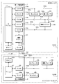
- FIG. 1 is a block diagram showing a configuration of an in-vehicle communication system according to the present embodiment.
- the in-vehicle communication system according to the present embodiment is a system in which a plurality of communication devices mounted on a vehicle having an automatic driving function communicate with each other. There are multiple places in the vehicle where these communication devices are installed.
- the vehicle interior area 100A includes, for example, a space on which a vehicle occupant is boarding and a space around the vehicle interior area 100A.
- the engine room area 100B is, for example, a space provided at the front of the vehicle and on which a prime mover such as an engine or a motor is mounted.
- the vehicle interior area 100A and the engine room area 100B are partitioned by, for example, a wall member or the like.
- a through hole is formed in the wall member. Electric wires such as communication lines and power lines are passed through the through holes, and electrical connections are made between the vehicle interior area 100A and the engine room area 100B via the electric wires.
- the vehicle interior area 100A is equipped with a first relay device 1, a main ADAS (Advanced Driver-Assistance Systems) 3A, an auxiliary ADAS 3B, a first camera 4A, and the like.
- the engine room area 100B is equipped with a second relay device 2, a second camera 4B, a main brake control device 5A, an auxiliary brake control device 5B, and the like.
- the "main brake control device” is abbreviated as “main brake”
- the "auxiliary brake control device” is abbreviated as "auxiliary brake”.
- These plurality of devices mounted on the vehicle are appropriately connected via communication lines such as a communication trunk line 61, an auxiliary communication line 62, a communication branch line 63a, 63b, 63c, 63d and a communication branch line 64a, 64b, 64c, 64d, 64e. It is connected and operates while exchanging information by communication.
- communication via the communication trunk line 61 and the communication branch lines 64a, 64b, 64c, 64d, 64e is performed according to the Ethernet communication standard.
- Communication via the auxiliary communication line 62 and the communication branch lines 63a, 63b, 63c, 63d is performed according to the CAN communication standard.
- the communication trunk line 61 and the auxiliary communication line 62 are communication lines arranged across the vehicle interior area 100A and the engine room area 100B of the vehicle through the through holes formed in the wall member serving as the above-mentioned partition.
- the communication trunk line 61 is a communication line that connects the first relay device 1 and the second relay device 2 on a one-to-one basis.
- the auxiliary communication line 62 includes a first auxiliary communication line 62a, an internal wiring 62b, and a second auxiliary communication line 62c.
- the first auxiliary communication line 62a connects the first relay device and the second relay device 2.
- the second auxiliary communication line 62c is a bus-type communication line that connects the second relay device 2, the main brake control device 5A, the auxiliary brake control device 5B, and the like.
- the internal wiring 62b is wiring provided inside the second relay device 2, and electrically connects the first auxiliary communication line 62a and the second auxiliary communication line 62c.
- the internal wiring 62b is, for example, a terminal to which the first auxiliary communication line 62a is connected, a terminal to which the second auxiliary communication line 62c is connected, a wiring pattern formed on a circuit board on which these terminals are mounted, or the like. is there.
- the communication branch line 63a is a bus-type communication line that connects the first relay device 1 and one or more devices including the main ADAS3A.
- the communication branch line 63b is a bus-type communication line that connects the first relay device 1 and one or more devices including the auxiliary ADAS3B.
- the communication branch line 63c is a bus-type communication line that connects the first relay device 1 and a plurality of devices including the main ADAS3A and the auxiliary ADAS3B.
- the communication branch line 63d is a bus-type communication line that connects the second relay device 2 and a plurality of devices including the main brake control device 5A and the auxiliary brake control device 5B.
- the communication branch line 64a is a communication line that connects the first relay device 1 and the main ADAS3A on a one-to-one basis.
- the communication branch line 64b is a communication line that connects the first relay device 1 and the auxiliary ADAS3B on a one-to-one basis.
- the communication branch line 64c is a communication line that connects the main ADAS3A and the first camera 4A on a one-to-one basis.
- the communication branch line 64d is a communication line that connects the auxiliary ADAS3B and the first camera 4A on a one-to-one basis.
- the communication branch line 64e is a communication line that connects the second relay device 2 and the second camera 4B on a one-to-one basis.
- Autonomous driving level 0 is a vehicle in which driving is not automated.
- Autonomous driving levels 1 to 3 are partially or limited autonomous driving and require the driver to be in the vehicle.
- Autonomous driving levels 4 and 5 are limited or fully autonomous driving, and the main body of driving is mechanical control, so that the driver does not need to board the vehicle.
- the vehicle according to the present embodiment may be one in which any of levels 1 to 5 is automatically driven.
- the main ADAS3A is a control device that controls driving related to automatic driving of the vehicle.
- the main ADAS3A operates the controlled devices such as the main brake control device 5A and the auxiliary brake control device 5B related to the running of the vehicle based on the information input from the input devices such as the first camera 4A and the second camera 4B. Control.
- the automatic driving of the vehicle is realized by the control of the main ADAS3A.
- the auxiliary ADAS3B controls the running of the vehicle on behalf of the main ADAS3A when a failure or malfunction of the main ADAS3A occurs.
- the auxiliary ADAS3B may be a device having the same configuration as the main ADAS3A, or may be a device having a different configuration.
- a device such as a body ECU of a vehicle may be configured to perform each process in a normal state and control the main ADAS3A in an emergency.
- the main ADAS3A and the auxiliary ADAS3B have the same configuration.
- the first camera 4A is mounted near the vehicle's room mirror, for example, and photographs the front of the vehicle.
- the first camera 4A is connected to the main ADAS3A via the communication branch line 64c, and is connected to the auxiliary ADAS3B via the communication branch line 64d.
- the first camera 4A inputs the data of the image in front of the vehicle acquired by photographing to the main ADAS3A and the auxiliary ADAS3B via the communication branch lines 64c and 64d, respectively.
- the second camera 4B is mounted on the front part of the vehicle body of the vehicle, for example, and photographs the front of the vehicle.
- the second camera 4B is connected to the second relay device 2 via a communication branch line 64e.
- the second camera 4B inputs the image data of the image in front of the vehicle acquired by photographing to the main ADAS3A and the auxiliary ADAS3B via the first relay device 1 and the second relay device 2, respectively.
- the devices for inputting information necessary for automatic driving of the vehicle are the first camera 4A and the second camera 4B, but the present invention is not limited to this.
- the input device may be, for example, a sensor that detects an object around the vehicle using ultrasonic waves, or various devices such as LiDAR (Light Detection And Ringing). Similar to the first camera 4A and the second camera 4B in the present embodiment, these input devices are preferably provided in both the vehicle interior area 100A and the engine room area 100B, respectively.
- the main brake control device 5A is a device that controls the brake of the vehicle.
- the main brake control device 5A activates the vehicle brake in response to a control command from the main ADAS3A or the auxiliary ADAS3B.
- the auxiliary brake control device 5B is a device that controls the brake of the vehicle in response to a control command of the main ADAS3A or the auxiliary ADAS3B, similarly to the main brake control device 5A.
- the auxiliary brake control device 5B controls the brake on behalf of the main brake control device 5A when a failure or malfunction of the main brake control device 5A occurs.
- the auxiliary brake control device 5B may have the same configuration as the main brake control device 5A, or may have a different configuration. In the present embodiment, the main brake control device 5A and the auxiliary brake control device 5B have the same configuration.
- the controlled devices controlled by the main ADAS3A and the auxiliary ADAS3B are the main brake control device 5A and the auxiliary brake control device 5B, but the present invention is not limited to this.
- the controlled device may be various devices such as a device for controlling a steering mechanism of a vehicle, a device for controlling an accelerator of a vehicle, and a device for controlling lighting such as a light of a vehicle.
- these controlled devices are preferably equipped with an auxiliary device that operates in an emergency, in addition to the device that operates in the normal state.
- the first relay device 1 includes a main microcomputer (microcontroller or microcomputer) 11, an auxiliary microcomputer 12, a plurality of CAN controllers 13a to 13d, and a plurality of Ethernet PHY (PHYsical layer) 14a to 14c.
- CAN controller is abbreviated as “CAN”
- Ethernet PHY is abbreviated as “PHY”.
- the first relay device 1 includes four CAN controllers 13a to 13d and three Ethernet PHYs 14a to 14c.
- the main microcomputer 11 is connected to two CAN controllers 13a and 13b and three Ethernet PHYs 14a to 14c.
- the main microcomputer 11 appropriately transmits a message received by any one of the CAN controllers 13a and 13b and the Ethernet PHYs 14a to 14c from the other CAN controllers 13a and 13b and the Ethernet PHYs 14a to 14c.
- the main microcomputer 11 performs a process of relaying the message.
- the CAN controller 13a is connected to the main ADAS3A and the like via the communication branch line 63a.
- the Ethernet PHY 14a is connected to the main ADAS3A via the communication branch line 64a.
- the Ethernet PHY 14c is connected to the second relay device 2 via the communication trunk line 61.
- the main microcomputer 11 transmits, for example, the image data of the second camera 4B received from the second relay device by the Ethernet PHY 14c to the main ADAS3A by the Ethernet PHY 14a.
- the main microcomputer 11 transmits a control command from the main ADAS3A received by the CAN controller 13a to the second relay device 2 via Ethernet PHY14c.
- the CAN controller 13b is connected to the auxiliary ADAS3B or the like via the communication branch line 63b.
- the Ethernet PHY 14b is connected to the auxiliary ADAS3B via the communication branch line 64b.
- the main microcomputer 11 transmits the image data of the second camera 4B received from the second relay device by the Ethernet PHY 14c to the auxiliary ADAS 3B by the Ethernet PHY 14b.
- the main microcomputer 11 transmits, for example, a control command from the auxiliary ADAS3B received by the CAN controller 13b to the second relay device 2 via Ethernet PHY14c.
- the main microcomputer 11 may relay the message regarding the auxiliary ADAS3B only when an abnormality or the like occurs in the main ADAS3A.
- the auxiliary microcomputer 12 relays the message by transmitting the message received by one CAN controller 13c, 13d from the other CAN controller 13c, 13d.
- the CAN controller 13c is connected to the main ADAS3A, the auxiliary ADAS3B, and the like via the communication branch line 63c.
- the CAN controller 13d is connected to the main brake control device 5A, the auxiliary brake control device 5B, and the like in the engine room area 100B via the auxiliary communication line 62.
- the auxiliary microcomputer 12 relays the communication between the main ADAS3A and the auxiliary ADAS3B and the main brake control device 5A and the auxiliary brake control device 5B.
- the message relay by the auxiliary microcomputer 12 may be performed only when the message relay by the main microcomputer 11 becomes impossible.
- the second relay device 2 is configured to include a microcomputer 21, a CAN controller 22, Ethernet PHY23a, 23b, and the like.
- the microcomputer 21 performs a process of relaying a message by appropriately transmitting a message received by any one of the CAN controller 22 and the Ethernet PHY 23a, 23b from the other CAN controller 22 and the Ethernet PHY 23a, 23b.
- the CAN controller 22 is connected to the main brake control device 5A, the auxiliary brake control device 5B, and the like via the communication branch line 63d.
- the Ethernet PHY 23a is connected to the first relay device 1 via the communication trunk line 61.
- the Ethernet PHY 23b is connected to the second camera 4B via the communication branch line 64e.
- the microcomputer 21 transmits, for example, the image data of the second camera 4B received by the Ethernet PHY 23b to the first relay device 1 by the Ethernet PHY 23a.
- the microcomputer 21 transmits a control command from the first relay device 1 received by the Ethernet PHY 23a to the main brake control device 5A or the auxiliary brake control device 5B by the CAN controller 22.
- the second relay device 2 includes a circuit board (not shown) on which a microcomputer 21, a CAN controller 22, Ethernet PHY23a, 23b, etc. are mounted.
- the circuit board is equipped with a connector to which the communication trunk line 61, the first auxiliary communication line 62a and the second auxiliary communication line 62c of the auxiliary communication line 62, the communication branch line 63d, and the communication branch line 64e are connected.
- the connector to which the first auxiliary communication line 62a is connected and the connector to which the second auxiliary communication line 62c is connected are electrically connected on the circuit board via the internal wiring 62b.
- the CAN controller 13d of the first relay device 1, the main brake control device 5A, the auxiliary brake control device 5B, and the like are electrically connected through the second relay device 2 and are electrically connected via the auxiliary communication line 62. Communication is possible.
- the internal wiring 62b of the circuit board may be provided with, for example, an amplifier circuit for amplifying a communication signal, a filter circuit for removing noise, or the like.
- a microcomputer 21, a CAN controller, or the like may intervene between the first auxiliary communication line 62a and the second auxiliary communication line 62c to perform relay processing.
- the vehicle is automatically brake-controlled by the control of the main brake control device 5A by the main ADAS3A in a normal state in which no abnormality or the like related to communication occurs.
- the main ADAS3A determines the situation in front of the vehicle based on the images in front of the vehicle obtained from the first camera 4A and the second camera 4B, and controls the braking operation. At this time, the image captured by the first camera 4A is directly input to the main ADAS3A via the communication branch line 64c.
- the images captured by the second camera 4B are the communication branch line 64e, the Ethernet PHY23b of the second relay device 2, the microcomputer 21, the Ethernet PHY23a, the communication trunk line 61, the Ethernet PHY14c of the first relay device 1, the main microcomputer 11, the Ethernet PHY14a, and communication. It is input to the main ADAS3A via the branch line 64a.
- the main ADAS3A transmits a control command for controlling the brake operation based on the input image data of the first camera 4A and the second camera 4B.
- the main ADAS3A does not require the image data of both the first camera 4A and the second camera 4B, and can control the brake operation based on the image data of either one.
- the brake control command by the main ADAS3A is the communication branch line 63a, the CAN controller 13a of the first relay device 1, the main microcomputer 11, the Ethernet PHY 14c, the communication trunk line 61, the Ethernet PHY 23a of the second relay device 2, the microcomputer 21, the CAN controller 22 and the like. It is given to the main brake control device 5A via the communication branch line 63d.
- the main brake control device 5A controls the operation of the vehicle brake in response to a given control command.
- the auxiliary ADAS3B controls the brake on behalf of the main ADAS3A.
- the image captured by the first camera 4A is directly input to the auxiliary ADAS3B via the communication branch line 64d.
- the images captured by the second camera 4B are the communication branch line 64e, the Ethernet PHY23b of the second relay device 2, the microcomputer 21, the Ethernet PHY23a, the communication trunk line 61, the Ethernet PHY14c of the first relay device 1, the main microcomputer 11, the Ethernet PHY14b, and communication. It is input to the auxiliary ADAS3B via the branch line 64b.
- the brake control command by the auxiliary ADAS3B is the communication branch line 63b, the CAN controller 13b of the first relay device 1, the main microcomputer 11, the Ethernet PHY 14c, the communication trunk line 61, the Ethernet PHY 23a of the second relay device 2, the microcomputer 21, the CAN controller 22 and the like. It is given to the main brake control device 5A via the communication branch line 63d.
- the auxiliary brake control device 5B controls the operation of the vehicle brake in place of the main brake control device 5A.
- the transmission / reception route of the control command from the main ADAS3A or the auxiliary ADAS3B to the auxiliary brake control device 5B is the same as the transmission / reception route of the control command from the main ADAS3A or the auxiliary ADAS3B to the main brake control device 5A.
- the first relay device 1 relays the communication by the auxiliary microcomputer 12 instead of the communication relay by the main microcomputer 11.
- the image data of the second camera 4B is not relayed via the auxiliary communication line 62, and the main ADAS3A controls based on the image data of the first camera 4A.
- the brake control command by the main ADAS3A is given to the main brake control device 5A via the communication branch line 63c, the CAN controller 13c, the auxiliary microcomputer 12, the CAN controller 13d, and the auxiliary communication line 62.
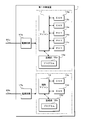
- FIG. 2 is a block diagram showing a configuration of the first relay device 1 according to the present embodiment.
- the first relay device 1 according to the present embodiment includes a main microcomputer 11, an auxiliary microcomputer 12, four CAN controllers 13a to 13d, three Ethernet PHYs 14a to 14c, two storage units (storage) 15a and 15b, and two power supplies. It is configured to include circuits 17a, 17b and the like.
- the main microcomputer 11 reads and executes the program 16a stored in the storage unit 15a to perform various processes related to message relay.
- the storage unit 15a is configured by using a non-volatile memory element such as a flash memory or an EEPROM (Electrically Erasable Programmable Read Only Memory).
- the storage unit 15a stores various programs executed by the main microcomputer 11 and various data required for processing of the main microcomputer 11.
- the auxiliary microcomputer 12 performs various processes related to message relay by reading and executing the program 16b stored in the storage unit 15b.
- the storage unit 15b is configured by using a non-volatile memory element such as a flash memory or EEPROM.
- the storage unit 15b stores various programs executed by the auxiliary microcomputer 12 and various data required for processing of the auxiliary microcomputer 12.
- the programs 16a and 16b may be written to the storage units 15a and 15b at the manufacturing stage of the first relay device 1, for example.
- the first relay device 1 may acquire what is distributed by a remote server device or the like by communication.
- a recording medium such as a memory card or an optical disk
- the writing device may read out what is recorded on the recording medium and write it in the storage units 15a and 15b of the first relay device 1.
- the programs 16a and 16b may be provided in a mode of distribution via a network, or may be provided in a mode recorded on a recording medium.
- the CAN controllers 13a to 13d send and receive messages according to the CAN communication protocol via the connected communication line.
- Each of the CAN controllers 13a to 13d can be configured as, for example, one IC.
- the CAN controllers 13a and 13b transmit a message to another device by converting a message for transmission given from the main microcomputer 11 into an electric signal corresponding to the communication standard of CAN and outputting it to a communication line.
- the CAN controllers 13a and 13b receive a message from another device by sampling and acquiring the potential of the communication line, and give the received message to the main microcomputer 11.
- the CAN controllers 13c and 13d convert the message for transmission given from the auxiliary microcomputer 12 into an electric signal corresponding to the communication standard of CAN and output the message to the communication line to transmit the message to other devices. I do.
- the CAN controllers 13b and 13c receive a message from another device by sampling and acquiring the potential of the communication line, and give the received message to the auxiliary microcomputer 12.
- Ethernet PHY14a to 14c transmit and receive messages according to the Ethernet communication protocol via the connected communication line.
- the Ethernet PHYs 14a to 14c can be configured as, for example, one IC each.
- the Ethernet PHYs 14a to 14c transmit a message to another device by converting a transmission message given from the main microcomputer 11 into an electric signal corresponding to the Ethernet communication standard and outputting it to a communication line.
- the Ethernet PHYs 14a to 14c receive a message from another device by sampling and acquiring the potential of the communication line, and give the received message to the main microcomputer 11.
- the power supply circuits 17a and 17b are connected to batteries mounted on the vehicle (not shown) via power lines 65a and 65b, respectively.
- the power supply circuits 17a and 17b convert, for example, 12V power supplied from a battery into electric power such as 5V or 3V.
- the power supply circuit 17a supplies electric power to the main microcomputer 11, the CAN controllers 13a and 13b, the Ethernet PHYs 14a to 14c, the storage unit 15a, and the like.
- the power supply circuit 17b supplies electric power to the auxiliary microcomputer 12, the CAN controllers 13c and 13d, the storage unit 15b, and the like.
- FIG. 3 is a block diagram showing the configuration of the second relay device 2 according to the present embodiment.
- the second relay device 2 includes a microcomputer 21, a CAN controller 22, two Ethernet PHYs 23a and 23b, a storage unit (storage) 24, a power supply circuit 26, an internal wiring 62b, and the like.
- the microcomputer 21 reads and executes the program 25 stored in the storage unit 24 to perform various processes related to message relay.
- the storage unit 24 is configured by using a non-volatile memory element such as a flash memory or EEPROM.
- the storage unit 24 stores various programs executed by the microcomputer 21 and various data required for processing of the microcomputer 21.
- the program 25 may be written in the storage unit 24, for example, at the manufacturing stage of the second relay device 2.
- the second relay device 2 may acquire what is distributed by a remote server device or the like by communication.
- a recording medium such as a memory card or an optical disk
- the program 25 may be read by the writing device and written in the storage unit 24 of the second relay device 2.
- the program 25 may be provided in a mode of distribution via a network, or may be provided in a mode recorded on a recording medium.
- the CAN controller 22 sends and receives messages according to the CAN communication protocol via the connected communication line.
- the CAN controller 22 can be configured as, for example, one IC.
- the CAN controller 22 transmits a message to another device by converting a message for transmission given from the microcomputer 21 into an electric signal corresponding to the communication standard of CAN and outputting it to a communication line.
- the CAN controller 22b receives a message from another device by sampling and acquiring the potential of the communication line, and gives the received message to the microcomputer 21.
- Ethernet PHY23a and 23b transmit and receive messages according to the Ethernet communication protocol via the connected communication line.
- the Ethernet PHYs 23a and 23b can be configured as, for example, one IC each.
- the Ethernet PHYs 23a and 23b transmit a message to another device by converting a transmission message given from the microcomputer 21 into an electric signal corresponding to the Ethernet communication standard and outputting the message to the communication line.
- the Ethernet PHYs 23a and 23b receive a message from another device by sampling and acquiring the potential of the communication line, and give the received message to the microcomputer 21.
- the power supply circuit 26 is connected to the battery mounted on the vehicle via the power line 65c.
- the power supply circuit 26 converts, for example, the 12V power supplied from the battery into a power such as 5V or 3V.
- the power supply circuit 26 supplies electric power to the microcomputer 21, the CAN controller 22, the Ethernet PHYs 23a and 23b, the storage unit 24, and the like.
- the internal wiring 62b can be provided as a hein pattern on a circuit board on which, for example, a microcomputer 21, a CAN controller 23, Ethernet PHY23a, 23b, a storage unit 24, and a power supply circuit 26 are mounted.
- the second relay device 2 includes a terminal to which the first auxiliary communication line 62a of the auxiliary communication line 62 is connected and a terminal to which the second auxiliary communication line 62c is connected.
- the internal wiring 62b is a wiring pattern that electrically connects the two terminals.
- FIG. 4 is a block diagram showing the configuration of the main ADAS3A according to the present embodiment. Since the configuration of the auxiliary ADAS3B according to the present embodiment is the same as the configuration of the main ADAS3A, the illustration and description of the block diagram will be omitted.
- the main ADAS3A according to the present embodiment is configured to include a processing unit (processor) 31, a storage unit (storage) 32, two CAN controllers 33a and 33b, and two Ethernet PHYs 34a and 34b.
- the processing unit 31 is configured by using an arithmetic processing unit such as a CPU (Central Processing Unit) or an MPU (Micro-Processing Unit). By reading and executing the program 32a stored in the storage unit 32, the processing unit 31 performs various processes such as traveling control related to automatic driving of the vehicle and switching control between automatic driving and manual driving.
- CPU Central Processing Unit
- MPU Micro-Processing Unit
- the storage unit 32 is configured by using a non-volatile memory element such as a flash memory or EEPROM.
- the storage unit 32 stores various programs executed by the processing unit 31 and various data required for processing by the processing unit 31.
- the program 32a may be written to the storage unit 32, for example, at the manufacturing stage of the main ADAS3A.
- the main ADAS3A may acquire what is distributed by a remote server device or the like by communication.
- a recording medium such as a memory card or an optical disk may be read by the main ADAS3A and stored in the storage unit 32.
- the writing device may read what has been recorded on the recording medium and write it in the storage unit 32 of the main ADAS3A.
- the program 32a may be provided in a mode of distribution via a network, or may be provided in a mode recorded on a recording medium.
- the CAN controllers 33a and 33b send and receive messages according to the CAN communication protocol via the connected communication line.
- the CAN controllers 33a and 33b can be configured as one IC, for example.
- the CAN controllers 33a and 33b convert the message for transmission given from the processing unit 31 into an electric signal corresponding to the communication standard of CAN and output it to the communication line to transmit the message to another device.
- the CAN controllers 33a and 33b receive a message from another device by sampling and acquiring the potential of the communication line, and give the received message to the processing unit 31.
- the Ethernet PHYs 34a and 34b send and receive messages according to the Ethernet communication protocol via the connected communication line.
- the Ethernet PHYs 34a and 34b can be configured as, for example, one IC each.
- the Ethernet PHYs 34a and 34b transmit a message to another device by converting a transmission message given from the processing unit 31 into an electric signal corresponding to the Ethernet communication standard and outputting the message to the communication line.
- the Ethernet PHYs 34a and 34b receive a message from another device by sampling and acquiring the potential of the communication line, and give the received message to the processing unit 31.
- the processing unit 31 reads out and executes the program 32a stored in the storage unit 32, so that the traveling control unit 31a, the switching control unit 31b, and the like function as software in the processing unit 31.
- the travel control unit 31a controls the operation of the main brake control device 5A, the auxiliary brake control device 5B, and the like based on the information input from the input devices such as the first camera 4A and the second camera 4B, thereby controlling the operation of the vehicle.
- Vehicle travel control may include, for example, control of vehicle acceleration, deceleration, stopping, left and right steering operations, turning on and off of turn signals and headlights, or wiper operation. The details of the traveling control of the vehicle will be omitted.
- the switching control unit 31b performs a process of switching between manual driving and automatic driving of the vehicle, for example, in response to a user operation on a switch provided in the vehicle interior of the vehicle.
- the switching control unit 31b determines whether or not both the communication path via the communication trunk line 61 and the communication path via the auxiliary communication line 62 can communicate with each other. To do.
- both communication paths are communicable, the switching control unit 31b switches from manual operation to automatic operation.
- the switching control unit 31b does not switch from the manual operation to the automatic operation, and displays a warning message or the like.
- the switching control unit 31b determines, for example, whether or not the driver is present in the driver's seat of the vehicle, whether or not the driver is in a driving state, and the like. Whether or not switching is possible is determined based on this.
- ⁇ Communication path switching process> there are two communication paths for transmitting and receiving messages between the vehicle interior area 100A and the engine room area 100B of the vehicle.
- One is a communication path via the communication trunk line 61
- the other is a communication path via the auxiliary communication line 62.
- a message is transmitted and received between the vehicle interior area 100A and the engine room area 100B by using the communication path via the communication trunk line 61 in a normal state in which no abnormality or the like related to communication occurs.
- a message is transmitted / received between the vehicle interior area 100A and the engine room area 100B by using the communication path via the auxiliary communication line 62.
- Switching from message transmission / reception using the communication path via the communication trunk line 61 to message transmission / reception using the communication path via the auxiliary communication line 62 may be performed under the initiative of any device included in the in-vehicle communication system.
- the first relay device 1 performs the switching of the communication path and a case where the ADAS performs the switching will be described.
- the auxiliary microcomputer 12 of the first relay device 1 periodically checks the operating status of the main microcomputer 11 and determines whether or not there is an abnormality in the main microcomputer 11. ..
- the auxiliary microcomputer 12 determines that an abnormality has occurred in the main microcomputer 11
- the auxiliary microcomputer 12 stops the main microcomputer 11.
- the auxiliary microcomputer 12 starts relaying a message between the communication branch line 63c connected to the CAN controller 13c and the auxiliary communication line 62 connected to the CAN controller 13d.
- the main microcomputer 11 may transmit a message notifying that the communication path is switched from the CAN controllers 13c and 13d.
- the devices such as the main ADAS3A and the auxiliary ADAS3B connected to the communication branch line 63c and the devices such as the main brake control device 5A and the auxiliary brake control device 5B connected to the auxiliary communication line 62 are messages. Switch the communication path to send and receive.
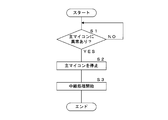
- FIG. 5 is a flowchart showing a procedure of communication path switching processing performed by the first relay device 1 according to the present embodiment.
- the auxiliary microcomputer 12 of the first relay device 1 according to the present embodiment determines the presence or absence of an abnormality in the main microcomputer 11 (step S1). If there is no abnormality (S1: NO), the auxiliary microcomputer 12 waits until an abnormality occurs in the main microcomputer 11. If there is an abnormality (S1: YES), the auxiliary microcomputer 12 stops the operation of the main microcomputer 11 (step S2). Next, the auxiliary microcomputer 12 starts the relay processing of the message received by the CAN controllers 13c and 13d (step S3), and ends the switching processing.
- the processing unit 31 of the main ADAS3A determines whether or not there is an abnormality in the communication route via the communication trunk line 61.
- the processing unit 31 receives a message from the second camera 4B, the main brake control device 5A, the auxiliary brake control device 5B, etc. mounted on the engine room area 100B of the vehicle by communication via, for example, the communication branch line 63a or the communication branch line 64a. Check for presence. If the message is not received for a predetermined period of time, the processing unit 31 can determine that an abnormality has occurred in the communication path via the communication trunk line 61.
- the processing unit 31 stops the communication using the communication path via the communication trunk line 61, and starts the communication using the communication path via the auxiliary communication line 62. At this time, the processing unit 31 may send a message instructing the switching of the communication path to one or more devices connected to the communication path via the auxiliary communication line 62.
- the auxiliary ADAS3B performs the same communication path switching process.
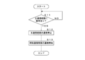
- FIG. 6 is a flowchart showing the procedure of the communication path switching process performed by the main ADAS3A according to the present embodiment.
- the communication path via the communication trunk line 61 is abbreviated as “main communication path”
- the communication path via the auxiliary communication line 62 is abbreviated as "auxiliary communication path”.
- the processing unit 31 of the main ADAS3A according to the present embodiment determines whether or not there is an abnormality in the communication path via the communication trunk line 61 (step S11). When it is determined that there is no abnormality (S11: NO), the processing unit 31 waits until an abnormality occurs without switching the communication path.
- the processing unit 31 stops the communication using the communication path via the communication trunk line 61 (step S12). Next, the processing unit 31 starts communication using the communication path via the auxiliary communication line 62 (step S13), and ends the switching process.
- ⁇ Switching process from manual operation to automatic operation> for example, switching from manual driving to automatic driving of the vehicle is performed in response to a user operation on a switch or the like provided in the vehicle interior of the vehicle.
- the main ADAS3A checks for abnormalities in the devices and systems related to automatic driving mounted on the vehicle.
- the main ADAS3A switches to automatic operation when it is determined that there is no abnormality.
- the main ADAS3A determines that there is an abnormality, it does not switch to automatic driving, and displays, for example, a warning message or the like notifying that an abnormality has occurred in automatic driving on a display or the like in the vehicle interior.
- the main ADAS3A includes communication using a communication path via the communication trunk line 61 and communication using a communication path via the auxiliary communication line 62 when switching from manual operation to automatic operation is requested. Judge the presence or absence of abnormality. When there is no abnormality in both communication paths, the main ADAS3A switches from manual operation to automatic operation, and the main brake control device 5A and the auxiliary are based on the information input from the first camera 4A, the second camera 4B, and the like. Control of the brake control device 5B and the like is started. When there is an abnormality in one of the communication paths, the main ADAS3A displays a warning message without switching from manual operation to automatic operation.
- a device such as a display for displaying a warning message is mounted on, for example, the vehicle interior area 100A of the vehicle, and is connected to the main ADAS3A or the first relay device 1 via a communication branch line.
- the main ADAS3A can display a warning message by communicating with a device such as a display via a communication branch line and the first relay device 1.
- FIG. 7 is a flowchart showing a procedure of switching processing from manual operation to automatic operation performed by the main ADAS3A according to the present embodiment.
- the communication path via the communication trunk line 61 is abbreviated as “main communication path”
- the communication path via the auxiliary communication line 62 is abbreviated as “auxiliary communication path”.
- the switching control unit 31b of the processing unit 31 of the main ADAS3A according to the present embodiment determines whether or not a request for switching from manual operation to automatic operation based on user operation has been given (step S21). When the switching request is not given (S21: NO), the switching control unit 31b maintains the manual operation and waits until the switching request is given.
- the switching control unit 31b confirms the operation of the communication path via the communication trunk line 61 (step S22). At this time, the switching control unit 31b confirms the operation of the second relay device 2, the main brake control device 5A, the auxiliary brake control device 5B, the second camera 4B, etc. by using the communication path via the communication trunk line 61, for example. Send a message. The switching control unit 31b can confirm the operation depending on whether or not there is a response to this message. Next, the switching control unit 31b confirms the operation of the communication path via the auxiliary communication line 62 (step S23).
- the switching control unit 31b transmits an operation confirmation message to the main brake control device 5A, the auxiliary brake control device 5B, and the like by using, for example, a communication path via the auxiliary communication line 62, and responds to this message.
- the operation can be confirmed by receiving.
- the switching control unit 31b determines whether or not communication is possible for both the communication path via the communication trunk line 61 and the communication path via the auxiliary communication line 62 ( Step S24).
- the switching control unit 31b switches from manual operation to automatic operation (step S25), and ends the process.
- the switching control unit 31b notifies an abnormality by displaying a warning message on the display (step S26), and ends the process. ..
- the area inside the vehicle on which various devices can be mounted is divided into at least two of the vehicle interior area 100A and the engine room area 100B.
- the vehicle interior area 100A is equipped with a main ADAS3A and an auxiliary ADAS3B for controlling the traveling of the vehicle, a first relay device 1 for relaying communication, and a first camera 4A for inputting information used for traveling control.
- the main brake control device 5A and the auxiliary brake control device 5B controlled by the main ADAS3A and the auxiliary ADAS3B, the second relay device 2 for relaying communication, and the second relay device 2 for inputting information used for driving control are input.
- a camera 4B is installed.
- the first relay device 1 and the second relay device 2 are connected via a communication trunk line 61 that straddles the two areas.
- the first relay device 1, the main brake control device 5A, and the auxiliary brake control device 5B are connected via an auxiliary communication line 62 straddling the two areas.
- the main ADAS3A and the auxiliary ADAS3B provided in the vehicle interior area 100A communicate with the main brake control device 5A and the auxiliary brake control device 5B provided in the engine room area 100B by using two communication paths. It becomes possible to do.
- the main ADAS3A and the auxiliary ADAS3B communicate with the main brake control device 5A and the auxiliary brake control device 5B by using the other communication path even if a problem occurs in one of the communication paths. be able to. Therefore, it is possible to improve the trust line related to the communication of the in-vehicle communication system.
- two control devices a main ADAS3A and an auxiliary ADAS3B
- the other control device can control the main brake control device 5A and the auxiliary brake control device 5B.
- the first camera 4A is mounted in the vehicle interior area 100A
- the second camera 4B is mounted in the engine room area 100B.
- the other camera can input information to the main ADAS3A and the auxiliary ADAS3B.
- two brake control devices a main brake control device 5A and an auxiliary brake control device 5B, are mounted on the vehicle.
- the main ADAS3A and the auxiliary ADAS3B can control the operation of the other brake control device and control the brake of the vehicle.
- auxiliary communication lines 62 connecting the main ADAS3A and the auxiliary ADAS3B in the vehicle interior area 100A and the main brake control device 5A and the auxiliary brake control device 5B in the engine room area 100B. It is provided separately.
- the auxiliary communication line 62 includes a first auxiliary communication line 62a, an internal wiring 62b, and a second auxiliary communication line 62c.
- the first auxiliary communication line 62a is a communication line connecting the first relay device 1 and the second relay device 2.
- the second auxiliary communication line 62c is a communication line connecting the second relay device 2, the main brake control device 5A, and the auxiliary brake control device 5B.
- the internal wiring 62b is wiring in the second relay device 2 that electrically connects the first auxiliary communication line 62a and the second auxiliary communication line 62c.
- the communication trunk line 61 and the auxiliary communication line 62 provided across the vehicle interior area 100A and the engine room area 100B of the vehicle are both connected to the first relay device 1 and the second relay device 2.
- the wire connection work can be facilitated.
- the communication trunk line 61 is a communication line that connects the first relay device 1 and the second relay device 2 on a one-to-one basis.
- the communication trunk line 61 is, for example, a communication line that complies with the Ethernet communication standard.
- the auxiliary communication line 62 is a bus-type communication line that connects the first relay device 1 with a plurality of devices such as the main brake control device 5A and the auxiliary brake control device 5B.
- the auxiliary communication line 62 is, for example, a communication line that conforms to the communication standard of CAN.
- the communication trunk line 61 according to the Ethernet communication standard is a communication line capable of high-speed communication of, for example, 100 Mbps
- the auxiliary communication line 62 according to the CAN communication standard is a communication line capable of low-speed communication of, for example, 1 Mbps.
- the first relay device 1 includes two microcomputers, a main microcomputer 11 and an auxiliary microcomputer 12, and two power supply circuits 17a and 17b.
- the main microcomputer 11 performs a process of relaying communication between the main ADAS3A and the auxiliary ADAS3B and the second relay device 2 via the communication trunk line 61.
- the auxiliary microcomputer 12 performs a process of relaying communication between the main ADAS3A and the auxiliary ADAS3B and the main brake control device 5A and the auxiliary brake control device 5B via the auxiliary communication line 62.
- One power supply circuit 17a supplies electric power to the main microcomputer 11.
- the other power supply circuit 17b supplies power to the auxiliary microcomputer 12.
- the auxiliary microcomputer 12 determines whether or not there is an abnormality related to the processing of the main microcomputer 11. When it is determined that there is an abnormality, the auxiliary microcomputer 12 relays the message via the auxiliary communication line 62. As a result, the first relay device 1 can switch between communication via the communication trunk line 61 and communication via the auxiliary communication line 62.
- the vehicle is equipped with an automatic driving function, and the occupant of the vehicle can switch between manual driving and automatic driving.
- the main ADAS3A and the auxiliary ADAS3B perform traveling control related to the automatic driving of the vehicle.
- the main ADAS3A and the auxiliary ADAS3B determine whether or not the communication by the communication trunk line 61 and the auxiliary communication line 62 is possible.
- the main ADAS3A and the auxiliary ADAS3B switch to automatic operation when communication is possible for both the communication trunk line 61 and the auxiliary communication line 62.
- the main ADAS3A and the auxiliary ADAS3B do not switch to automatic operation when communication is not possible for at least one of the communication trunk line 61 and the auxiliary communication line 62. As a result, it is possible to prevent switching from manual operation to automatic operation in a state where the reliability of communication is lowered.
- the device for inputting information to the main ADAS3A and the auxiliary ADAS3B is a camera, but the present invention is not limited to this.
- the input device may be various devices such as an ultrasonic sensor or LiDAR.
- the controlled devices controlled by the main ADAS3A and the auxiliary ADAS3B are the main brake control device 5A and the auxiliary brake control device 5B, but the present invention is not limited to this.
- the controlled device may be various devices such as a steering wheel, an accelerator, an indicator, a light and a wiper.
- the control device for controlling the running of the vehicle is ADAS, but the present invention is not limited to this.
- the control device may be various devices other than ADAS.
- the area in which the device can be mounted in the vehicle is divided into two areas, the vehicle interior area 100A and the engine room area 100B, but the present invention is not limited to this.
- the mounting area of the device may be divided into three or more, and a communication trunk line and an auxiliary communication line are provided for communication across the two areas.
- the arrangement of the devices and the connection of communication lines shown in FIG. 1 are examples, and are not limited thereto.
- the number of CAN controllers mounted and the number of Ethernet PHYs mounted are examples, and are not limited thereto.
- the communication trunk line 61 is a communication line conforming to the Ethernet communication standard
- the auxiliary communication line 62 is a communication line conforming to the CAN communication standard, but the present invention is not limited to this.
- both the communication trunk line 61 and the auxiliary communication line 62 may be communication lines that comply with the Ethernet communication standard.
- Both the communication trunk line 61 and the auxiliary communication line 62 may be communication lines that comply with the CAN communication standard.
- the communication trunk line 61 and the auxiliary communication line 62 may be communication powers that comply with communication standards different from Ethernet and CAN.
- the communication standard can be selected as appropriate.
- Each device in the in-vehicle communication system includes a computer including a microprocessor, ROM, RAM, and the like.
- An arithmetic processing unit such as a microprocessor reads a computer program including a part or all of each step of a sequence diagram or a flowchart as shown in FIGS. 5 to 7 from a storage unit such as a ROM or RAM and executes the program. You can.
- the computer programs of these plurality of devices can be installed from an external server device or the like. Further, the computer programs of these plurality of devices are distributed in a state of being stored in a recording medium such as a CD-ROM, a DVD-ROM, or a semiconductor memory, respectively.
Landscapes
- Engineering & Computer Science (AREA)
- Automation & Control Theory (AREA)
- Mechanical Engineering (AREA)
- Computer Networks & Wireless Communication (AREA)
- Signal Processing (AREA)
- Human Computer Interaction (AREA)
- Transportation (AREA)
- Small-Scale Networks (AREA)
- Cable Transmission Systems, Equalization Of Radio And Reduction Of Echo (AREA)
Abstract
通信の信頼性を向上する車載通信システム、車載中継装置及び車載制御装置を提供する。 第1中継装置は車両の第1エリアに搭載され、第2中継装置は第2エリアに搭載される。第1中継装置及び第2中継装置は、第1エリア及び第2エリアを跨いで通信幹線を介して接続される。主制御装置及び補助制御装置は、第1エリアに搭載され、第1中継装置に通信支線を介して接続される。被制御装置は、第2エリアに搭載され、第2中継装置に通信支線を介して接続される。第1入力装置は、第1エリアに搭載され、主制御装置又は補助制御装置へ情報を入力する。第2入力装置は、第2エリアに搭載され、第2中継装置に通信支線を介して接続され、第1中継装置及び第2中継装置を介して情報を主制御装置又は補助制御装置へ入力する。第1中継装置及び被制御装置は、第1エリア及び第2エリアを跨いで設けられた補助通信線を介して通信を行う。
Description
本開示は、車両に搭載された複数の装置が通信線を介した通信を行う車載通信システム、並びに、このシステムを構成する車載中継装置及び車載制御装置に関する。
近年、車両に搭載されるECU(Electronic Control Unit)等の装置は増加する傾向にある。各装置は、他の装置との間で通信を行って情報を交換し、各々の処理を行っている。このため、車両内の装置の増加に伴って、装置が通信を行うために設けられる車両内の通信線の量が増加している。
特許文献1においては、車両内を複数の領域に分け、領域毎に複数の機能ECUを第1ネットワークにて中継ECUに接続し、複数の中継ECUを第2ネットワークにて接続した構成の車両制御システムが記載されている。
しかしながら特許文献1に記載の車両制御システムにおいて、中継ECU間の通信線に短絡又は断線等の異常が発生する虞がある。車両制御システムにおいて、通信線に対するメッセージの送受信を行う通信IC(Integrated Circuit)に異常が発生する虞がある。このような異常が発生した場合、車両制御システムでは、第1ネットワークの機能ECUと第2ネットワークの機能ECUとがメッセージの送受信を行うことができなくなる虞がある。
本開示は、斯かる事情に鑑みてなされたものであって、その目的とするところは、車両内の通信の信頼性を向上することが期待できる車載通信システム、車載中継装置及び車載制御装置を提供することにある。
本態様に係る車載通信システムは、車両の第1エリアに搭載される第1中継装置と、前記車両の第2エリアに搭載され、前記第1エリア及び前記第2エリアを跨いで通信幹線を介して前記第1中継装置に接続される第2中継装置と、前記第1エリアに搭載され、前記第1中継装置に通信支線を介して接続され、前記車両の走行制御を行う主制御装置及び補助制御装置と、前記第2エリアに搭載され、前記第2中継装置に通信支線を介して接続され、前記主制御装置又は前記補助制御装置に制御される被制御装置と、前記第1エリアに搭載され、前記走行制御に用いる情報を前記主制御装置又は前記補助制御装置へ入力する第1入力装置と、前記第2エリアに搭載され、前記第2中継装置に通信支線を介して接続され、前記走行制御に用いる情報を前記第1中継装置及び前記第2中継装置を介して前記主制御装置又は前記補助制御装置へ入力する第2入力装置と、前記第1中継装置及び前記被制御装置は、前記第1エリア及び前記第2エリアを跨いで設けられた補助通信線を介して通信を行い、前記主制御装置及び前記補助制御装置は、前記通信幹線を介した通信を行うことができない場合に、前記補助通信線を介して前記被制御装置との通信を行い、前記補助制御装置は、前記主制御装置が前記被制御装置の制御を行うことができない場合に、前記被制御装置の制御を行う。
本願は、このような特徴的な処理部を備える車載中継装置又は車載制御装置等の装置として実現することができるだけでなく、かかる特徴的な処理をステップとする通信方法として実現したり、かかるステップをコンピュータに実行させるためのコンピュータプログラムとして実現したりすることができる。これらの装置の一部又は全部を実現する半導体集積回路として実現したり、これらの装置を含むその他の装置又はシステムとして実現したりすることができる。
上記によれば、車両内の通信の信頼性を向上することが期待できる。
[本開示の実施の形態の説明]
最初に本開示の実施態様を列記して説明する。以下に記載する実施形態の少なくとも一部を任意に組み合わせてもよい。
最初に本開示の実施態様を列記して説明する。以下に記載する実施形態の少なくとも一部を任意に組み合わせてもよい。
(1)本態様に係る車載通信システムは、車両の第1エリアに搭載される第1中継装置と、前記車両の第2エリアに搭載され、前記第1エリア及び前記第2エリアを跨いで通信幹線を介して前記第1中継装置に接続される第2中継装置と、前記第1エリアに搭載され、前記第1中継装置に通信支線を介して接続され、前記車両の走行制御を行う主制御装置及び補助制御装置と、前記第2エリアに搭載され、前記第2中継装置に通信支線を介して接続され、前記主制御装置又は前記補助制御装置に制御される被制御装置と、前記第1エリアに搭載され、前記走行制御に用いる情報を前記主制御装置又は前記補助制御装置へ入力する第1入力装置と、前記第2エリアに搭載され、前記第2中継装置に通信支線を介して接続され、前記走行制御に用いる情報を前記第1中継装置及び前記第2中継装置を介して前記主制御装置又は前記補助制御装置へ入力する第2入力装置と、前記第1中継装置及び前記被制御装置は、前記第1エリア及び前記第2エリアを跨いで設けられた補助通信線を介して通信を行い、前記主制御装置及び前記補助制御装置は、前記通信幹線を介した通信を行うことができない場合に、前記補助通信線を介して前記被制御装置との通信を行い、前記補助制御装置は、前記主制御装置が前記被制御装置の制御を行うことができない場合に、前記被制御装置の制御を行う。
本態様にあっては、制御装置及び中継装置等の種々の装置を搭載可能な車両内の領域が、第1エリア及び第2エリアの少なくとも2つに区分けされる。第1エリアには、車両の走行制御を行う主制御装置及び補助制御装置と、通信を中継する第1中継装置と、走行制御に用いる情報を入力する第1入力装置とが搭載される。第2エリアには、制御装置により制御される被制御装置と、通信を中継する第2中継装置と、走行制御に用いる情報を入力する第2入力装置とが搭載される。第1中継装置及び第2中継装置は、第1エリア及び第2エリアを跨いで通信幹線を介して接続される。第1中継装置及び被制御装置は、第1エリア及び第2エリアを跨いで補助通信線を介して接続される。
これにより、第1エリアに設けられた主制御装置及び補助制御装置は、第2エリアに設けられた被制御装置との通信を、通信幹線を介した通信経路と、補助通信線を介した通信経路との2つを利用して行うことが可能となる。主制御装置及び補助制御装置は、いずれか一方の通信経路に不具合等が発生した場合であっても、もう一方の通信経路を利用して被制御装置との通信を行うことができる。よって、車載通信システムの通信に係る信頼性を向上することができる。
主制御装置及び補助制御装置の2つの制御装置を車両に搭載することによって、いずれか一方の制御装置に不具合等が発生した場合であっても、もう一方の制御装置が被制御装置の制御を行うことができる。
第1エリアに第1入力装置を設け、第2エリアに第2入力装置を設けることによって、いずれか一方の入力装置に不具合等が発生した場合であっても、もう一方の入力装置が主制御装置及び補助制御装置へ情報を入力することができる。
(2)前記補助通信線は、前記第1エリア及び前記第2エリアを跨いで前記第1中継装置及び前記第2中継装置を接続する第1補助通信線と、前記第2中継装置及び前記被制御装置を接続する第2補助通信線と、前記第2中継装置内に設けられ、前記第1補助通信線及び前記第2補助通信線を電気的に接続する内部配線とを含むことが好ましい。
本態様にあっては、第1エリアの主制御装置及び補助制御装置と第2エリアの被制御装置とを接続する補助通信線は、いくつかの線に分割して設けられてもよい。例えば補助通信線は、第1中継装置及び第2中継装置を接続する第1補助通信線と、第2中継装置及び被制御装置を接続する第2補助通信線と、第1補助通信線及び第2補助通信線を電気的に接続する第2中継装置内の内部配線とを含んで構成されてよい。これにより、車両の第1エリア及び第2エリアを跨いで設けられる通信幹線及び補助通信線が共に第1中継装置及び第2中継装置に接続される態様となるため、通信線の接続作業等を容易化することができる。
(3)前記通信幹線は、前記第1中継装置及び前記第2中継装置を一対一に接続する高速通信線であり、前記補助通信線は、前記第1中継装置及び前記被制御装置を接続するバス型の低速通信線であることが好ましい。
本態様にあっては、通信幹線は、第1中継装置及び第2中継装置を一対一に接続する高速通信線である。例えば通信幹線は、イーサネット(登録商標)の通信規格に従う通信線である。補助通信線は、第1中継装置と一又は複数の被制御装置とを接続するバス型の低速通信線である。例えば補助通信線は、CAN(Controller Area Network)の通信規格に従う通信線である。これにより、補助通信線を設けることによる車載通信システムのコスト増大を抑制することが期待できる。
(4)前記第1中継装置は、主処理部と、補助処理部と、主電源回路と、補助電源回路とを有し、前記主処理部は、前記主制御装置及び前記補助制御装置、並びに、前記第2中継装置の間の通信を、前記通信幹線を介して中継する処理を行い、前記補助処理部は、前記主制御装置及び前記補助制御装置、並びに、前記被制御装置の間の通信を、前記補助通信線を介して中継する処理を行い、前記主電源回路は、前記主処理部へ電力を供給し、前記補助電源回路は、前記補助処理部へ電力を供給することが好ましい。
本態様にあっては、第1中継装置が、主処理部及び補助処理部の2つの処理部と、主電源回路及び補助電源回路の2つの電源回路を備える。主処理部は、通信幹線を介して、主制御装置及び補助制御装置と第2中継装置との間の通信を中継する処理を行う。補助処理部は、補助通信線を介して、主制御装置及び補助制御装置と被制御装置との間の通信を中継する処理を行う。主電源回路は主処理部へ電力を供給する。補助電源回路は補助処理部へ電力を供給する。第1中継装置に処理部及び電源回路の組を2つ設けることにより、第1中継装置の故障等に対する耐性を高めることができる。
(5)前記補助処理部は、前記主処理部の異常の有無を判定し、異常がある場合に前記補助通信線を介した中継処理を行うことが好ましい。
本態様にあっては、第1中継装置の補助処理部が、主処理部の処理に係る異常の有無を判定する。異常があると判定した場合、補助処理部が補助通信線を介した中継処理を行う。これにより、通信幹線を介した通信と補助通信線を介した通信とのいずれを行うかを第1中継装置が判断して切り替えることが可能となる。
(6)前記主制御装置及び前記補助制御装置は、前記車両の自動運転に係る走行制御を行う装置であり、前記車両が手動運転から自動運転への切り替えを要求された場合に、前記通信幹線及び前記補助通信線による通信の可否を判定し、前記通信幹線及び前記補助通信線による通信が可能である場合に、自動運転への切り替えを行うことが好ましい。
本態様にあっては、車両は自動運転機能を搭載した車両であり、車両の乗員により自動運転と手動運転との切り替えが可能である。主制御装置及び補助制御装置は、車両の自動運転に係る走行制御を行う。主制御装置及び補助制御装置は、手動運転から自動運転への切り替えを要求された場合、通信幹線及び補助通信線を介した通信の可否を判定する。主制御装置及び補助制御装置は、通信幹線及び補助通信線の両方について通信が可能である場合に、自動運転への切り替えを行う。主制御装置及び補助制御装置は、通信幹線及び補助通信線のいずれか一方について通信が不可能である場合、自動運転への切り替えを行わない。これにより、通信の信頼性が低下した状態で自動運転への切り替えが行われることを防止できる。
(7)本態様に係る車載中継装置は、車両に搭載される車載中継装置であって、主処理部、補助処理部、主電源回路及び補助電源回路を備え、前記主電源回路は、前記主処理部へ電力を供給し、前記補助電源回路は、前記補助処理部へ電力を供給し、前記主処理部は、前記車両の走行制御を行う主制御装置及び補助制御装置と前記主制御装置及び前記補助制御装置に制御される被制御装置が接続された他の中継装置との間の通信を、通信幹線を介して中継する処理を行い、前記補助処理部は、前記主処理部の中継に係る処理の異常の有無を判定し、異常がある場合に、前記主制御装置及び前記補助制御装置、並びに、前記被制御装置の間の通信を、補助通信線を介して中継する処理を行う。
本態様にあっては、態様(4)と同様に、車載中継装置の故障等に対する耐性を高めることができる。
(8)本態様に係る車載制御装置は、自動運転及び手動運転の切り替えが可能な車両に搭載され、前記車両の走行制御を行う車載制御装置であって、処理部を備え、前記処理部は、前記車両が手動運転から自動運転への切り替えが要求された場合に、通信幹線を介した被制御装置との通信及び補助通信線を介した前記被制御装置との通信の可否を判定し、前記通信幹線及び前記補助通信線による通信が可能である場合に、自動運転への切り替えを行う。
本態様にあっては、態様(6)と同様に、通信の信頼性が低下した状態で自動運転への切り替えが行われることを防止できる。
[本開示の実施形態の詳細]
本開示の実施形態に係る車載通信システムの具体例を、以下に図面を参照しつつ説明する。本開示はこれらの例示に限定されるものではなく、請求の範囲によって示され、請求の範囲と均等の意味及び範囲内でのすべての変更が含まれることが意図される。
本開示の実施形態に係る車載通信システムの具体例を、以下に図面を参照しつつ説明する。本開示はこれらの例示に限定されるものではなく、請求の範囲によって示され、請求の範囲と均等の意味及び範囲内でのすべての変更が含まれることが意図される。
<システム構成>
図1は、本実施の形態に係る車載通信システムの構成を示すブロック図である。本実施の形態に係る車載通信システムは、自動運転機能を有する車両に搭載された複数の通信装置が通信を行うシステムである。車両にはこれらの通信装置を搭載する場所が複数存在する。本実施の形態においては、車両の車室内エリア100A及びエンジンルームエリア100Bにそれぞれ複数の通信装置を搭載することが可能である。車室内エリア100Aは、例えば車両の乗員が搭乗する空間及びその周囲の空間を含む。エンジンルームエリア100Bは、例えば車両の前部に設けられ、エンジン又はモータ等の原動機が搭載される空間である。車室内エリア100A及びエンジンルームエリア100Bは、例えば壁部材等により仕切られている。壁部材には貫通孔が形成されている。貫通孔には通信線及び電力線等の電線が通され、この電線を介して車室内エリア100A及びエンジンルームエリア100Bの間の電気的な接続が行われる。
図1は、本実施の形態に係る車載通信システムの構成を示すブロック図である。本実施の形態に係る車載通信システムは、自動運転機能を有する車両に搭載された複数の通信装置が通信を行うシステムである。車両にはこれらの通信装置を搭載する場所が複数存在する。本実施の形態においては、車両の車室内エリア100A及びエンジンルームエリア100Bにそれぞれ複数の通信装置を搭載することが可能である。車室内エリア100Aは、例えば車両の乗員が搭乗する空間及びその周囲の空間を含む。エンジンルームエリア100Bは、例えば車両の前部に設けられ、エンジン又はモータ等の原動機が搭載される空間である。車室内エリア100A及びエンジンルームエリア100Bは、例えば壁部材等により仕切られている。壁部材には貫通孔が形成されている。貫通孔には通信線及び電力線等の電線が通され、この電線を介して車室内エリア100A及びエンジンルームエリア100Bの間の電気的な接続が行われる。
本実施の形態において車室内エリア100Aには、第1中継装置1、主ADAS(Advanced Driver-Assistance Systems)3A、補助ADAS3B及び第1カメラ4A等が搭載されている。エンジンルームエリア100Bには、第2中継装置2、第2カメラ4B、主ブレーキ制御装置5A及び補助ブレーキ制御装置5B等が搭載されている。なお図1においては、「主ブレーキ制御装置」を「主ブレーキ」と略示し、「補助ブレーキ制御装置」を「補助ブレーキ」と略示している。車両に搭載されたこれら複数の装置は、通信幹線61、補助通信線62、通信支線63a,63b,63c,63d及び通信支線64a,64b,64c,64d,64e等の通信線を介して適宜に接続され、通信により情報交換しながら動作している。本実施の形態においては、通信幹線61及び通信支線64a,64b,64c,64d,64eを介した通信は、イーサネットの通信規格に従って行われる。また補助通信線62及び通信支線63a,63b,63c,63dを介した通信は、CANの通信規格に従って行われる。
通信幹線61及び補助通信線62は、上述の仕切となる壁部材に形成された貫通孔を通して、車両の車室内エリア100A及びエンジンルームエリア100Bに跨って配される通信線である。通信幹線61は、第1中継装置1及び第2中継装置2を一対一に接続する通信線である。補助通信線62は、第1補助通信線62a、内部配線62b及び第2補助通信線62cを含んで構成されている。第1補助通信線62aは、第1中継装置及び第2中継装置2を接続する。第2補助通信線62cは、第2中継装置2と主ブレーキ制御装置5A及び補助ブレーキ制御装置5B等とを接続するバス型の通信線である。内部配線62bは、第2中継装置2の内部に設けられた配線であり、第1補助通信線62a及び第2補助通信線62cを電気的に接続する。内部配線62bは、例えば第1補助通信線62aが接続される端子、第2補助通信線62cが接続される端子、及び、これらの端子が搭載された回路基板上に形成された配線パターン等である。
通信支線63aは、第1中継装置1と、主ADAS3Aを含む一又は複数の装置とを接続するバス型の通信線である。通信支線63bは、第1中継装置1と、補助ADAS3Bを含む一又は複数の装置とを接続するバス型の通信線である。通信支線63cは、第1中継装置1と、主ADAS3A及び補助ADAS3Bを含む複数の装置とを接続するバス型の通信線である。通信支線63dは、第2中継装置2と、主ブレーキ制御装置5A及び補助ブレーキ制御装置5Bを含む複数の装置とを接続するバス型の通信線である。
通信支線64aは、第1中継装置1と主ADAS3Aとを一対一に接続する通信線である。通信支線64bは、第1中継装置1と、補助ADAS3Bとを一対一に接続する通信線である。通信支線64cは、主ADAS3Aと第1カメラ4Aとを一対一に接続する通信線である。通信支線64dは、補助ADAS3Bと第1カメラ4Aとを一対一に接続する通信線である。通信支線64eは、第2中継装置2と第2カメラ4Bとを一対一に接続する通信線である。
車両の自動運転は、例えばSAE(Society of Automotive Engineers)が定めた6段階のレベル(レベル0~5)により、自動運転における自動化の程度が示される。自動運転レベル0は、運転の自動化がなされていない自動車である。自動運転レベル1~3は、部分的又は限定的な自動運転であり、自動車に運転者が搭乗している必要がある。自動運転レベル4,5は、限定的又は完全な自動運転であり、運転の主体は機械制御となるため、自動車に運転者が搭乗する必要がない。本実施の形態に係る車両は、レベル1から5までのいずれの自動運転が行われるものであってもよい。
主ADAS3Aは、車両の自動運転に関する走行制御を行う制御装置である。主ADAS3Aは、第1カメラ4A及び第2カメラ4B等の入力装置から入力される情報に基づいて、主ブレーキ制御装置5A及び補助ブレーキ制御装置5B等の車両の走行に係る被制御装置の動作を制御する。主ADAS3Aの制御により、車両の自動運転が実現される。補助ADAS3Bは、主ADAS3Aの故障又は不具合等の発生時に、主ADAS3Aに代わって車両の走行を制御する。補助ADAS3Bは、主ADAS3Aと同じ構成の装置であってもよく、異なる構成の装置であってもよい。例えば、車両のボディECU等の装置が、通常時には各々の処理を行い、非常時に主ADAS3Aの制御を行う構成であってもよい。ただし本実施の形態においては、主ADAS3A及び補助ADAS3Bは同じ構成の装置とする。
第1カメラ4Aは、例えば車両のルームミラーの近傍に搭載され、車両の前方を撮影する。第1カメラ4Aは、主ADAS3Aに通信支線64cを介して接続され、補助ADAS3Bに通信支線64dを介して接続されている。第1カメラ4Aは、撮影により取得した車両前方の画像のデータを、各通信支線64c,64dを介して、主ADAS3A及び補助ADAS3Bにそれぞれ入力する。第2カメラ4Bは、例えば車両の車体前部に搭載され、車両の前方を撮影する。第2カメラ4Bは、第2中継装置2に通信支線64eを介して接続されている。第2カメラ4Bは、撮影により取得した車両前方の画像のデータを、第1中継装置1及び第2中継装置2を介して、主ADAS3A及び補助ADAS3Bにそれぞれ入力する。
なお本実施の形態においては、車両の自動運転に必要な情報を入力する装置を第1カメラ4A及び第2カメラ4Bとするが、これに限るものではない。入力装置は、例えば超音波を利用して車両周囲の物を検出するセンサ、又は、LiDAR(Light Detection And Ranging)等の種々の装置であってよい。これらの入力装置は、本実施の形態における第1カメラ4A及び第2カメラ4Bと同様に、車室内エリア100A及びエンジンルームエリア100Bの両方にそれぞれ設けられることが好ましい。
主ブレーキ制御装置5Aは、車両のブレーキを制御する装置である。主ブレーキ制御装置5Aは、主ADAS3A又は補助ADAS3Bからの制御命令に応じて、車両のブレーキを作動させる。これにより主ADAS3A及び補助ADAS3Bは、車両の減速及び停車等を実施できる。補助ブレーキ制御装置5Bは、主ブレーキ制御装置5Aと同様に、主ADAS3A又は補助ADAS3Bの制御命令に応じて車両のブレーキを制御する装置である。補助ブレーキ制御装置5Bは、主ブレーキ制御装置5Aの故障又は不具合等の発生時に、主ブレーキ制御装置5Aに代わってブレーキの制御を行う。補助ブレーキ制御装置5Bは、主ブレーキ制御装置5Aと同じ構成の装置であってもよく、異なる構成の装置であってもよい。本実施の形態においては、主ブレーキ制御装置5A及び補助ブレーキ制御装置5Bは同じ構成の装置とする。
なお本実施の形態においては、主ADAS3A及び補助ADAS3Bにより制御される被制御装置を主ブレーキ制御装置5A及び補助ブレーキ制御装置5Bとするが、これに限るものではない。被制御装置は、例えば車両のステアリング機構を制御する装置、車両のアクセルを制御する装置、及び、車両のライト等の照明を制御する装置等の種々の装置であってよい。これらの被制御装置は、主ブレーキ制御装置5A及び補助ブレーキ制御装置5Bと同様に、通常時に動作する装置と別に、非常時に動作する補助装置が搭載されることが好ましい。
第1中継装置1は、主マイコン(マイクロコントローラ又はマイクロコンピュータ)11、補助マイコン12、複数のCANコントローラ13a~13d及び複数のイーサネットPHY(PHYsical layer)14a~14cを備えて構成されている。なお図1においては、「CANコントローラ」を「CAN」と略示し、「イーサネットPHY」を「PHY」と略示している。本実施の形態において第1中継装置1は、4つのCANコントローラ13a~13dと、3つのイーサネットPHY14a~14cとを備えている。
主マイコン11は、2つのCANコントローラ13a,13bと、3つのイーサネットPHY14a~14cとが接続されている。主マイコン11は、CANコントローラ13a,13b及びイーサネットPHY14a~14cのいずれかにて受信したメッセージを、適宜に他のCANコントローラ13a,13b及びイーサネットPHY14a~14cから送信する。これにより主マイコン11は、メッセージを中継する処理を行う。CANコントローラ13aは、通信支線63aを介して主ADAS3A等に接続されている。イーサネットPHY14aは、通信支線64aを介して主ADAS3Aに接続されている。イーサネットPHY14cは、通信幹線61を介して第2中継装置2に接続されている。主マイコン11は、例えばイーサネットPHY14cにて第2中継装置から受信した第2カメラ4Bの画像データを、イーサネットPHY14aにて主ADAS3Aへ送信する。主マイコン11は、例えばCANコントローラ13aにて受信した主ADAS3Aからの制御命令を、イーサネットPHY14cにて第2中継装置2へ送信する。
CANコントローラ13bは、通信支線63bを介して補助ADAS3B等に接続されている。イーサネットPHY14bは、通信支線64bを介して補助ADAS3Bに接続されている。主マイコン11は、例えば例えばイーサネットPHY14cにて第2中継装置から受信した第2カメラ4Bの画像データを、イーサネットPHY14bにて補助ADAS3Bへ送信する。主マイコン11は、例えばCANコントローラ13bにて受信した補助ADAS3Bからの制御命令を、イーサネットPHY14cにて第2中継装置2へ送信する。ただし主マイコン11は、補助ADAS3Bに関するメッセージの中継を、主ADAS3Aに異常等が生じた場合に限定して行ってもよい。
補助マイコン12は、2つのCANコントローラ13c,13dが接続されている。補助マイコン12は、一方のCANコントローラ13c,13dにて受信したメッセージを、他方のCANコントローラ13c,13dから送信することで、メッセージを中継する。CANコントローラ13cは、通信支線63cを介して、主ADAS3A及び補助ADAS3B等に接続されている。CANコントローラ13dは、補助通信線62を介して、エンジンルームエリア100Bの主ブレーキ制御装置5A及び補助ブレーキ制御装置5B等に接続されている。補助マイコン12は、主ADAS3A及び補助ADAS3Bと、主ブレーキ制御装置5A及び補助ブレーキ制御装置5Bとの間の通信を中継する。ただし補助マイコン12によるメッセージの中継は、主マイコン11によるメッセージの中継が不可能となった場合等に限定して行ってもよい。
第2中継装置2は、マイコン21、CANコントローラ22及びイーサネットPHY23a,23b等を備えて構成されている。マイコン21は、CANコントローラ22及びイーサネットPHY23a,23bのいずれかにて受信したメッセージを、適宜に他のCANコントローラ22及びイーサネットPHY23a,23bから送信することで、メッセージを中継する処理を行う。CANコントローラ22は、通信支線63dを介して主ブレーキ制御装置5A及び補助ブレーキ制御装置5B等に接続されている。イーサネットPHY23aは、通信幹線61を介して第1中継装置1に接続されている。イーサネットPHY23bは、通信支線64eを介して第2カメラ4Bに接続されている。
マイコン21は、例えばイーサネットPHY23bにて受信した第2カメラ4Bの画像データを、イーサネットPHY23aにて第1中継装置1へ送信する。マイコン21は、例えばイーサネットPHY23aにて受信した第1中継装置1からの制御命令を、CANコントローラ22にて主ブレーキ制御装置5A又は補助ブレーキ制御装置5Bへ送信する。
また第2中継装置2は、マイコン21、CANコントローラ22及びイーサネットPHY23a,23b等が搭載される回路基板(図示は省略する)を備えている。この回路基板には、通信幹線61、補助通信線62の第1補助通信線62a及び第2補助通信線62c、通信支線63d、並びに、通信支線64eが接続されるコネクタが搭載されている。第1補助通信線62aが接続されるコネクタ及び第2補助通信線62cが接続されるコネクタは、回路基板上で内部配線62bを介して電気的に接続されている。このため、第1中継装置1のCANコントローラ13dと、主ブレーキ制御装置5A及び補助ブレーキ制御装置5B等とは、第2中継装置2をスルーして電気的に接続され、補助通信線62を介した通信が可能である。なお回路基板の内部配線62bには、例えば通信の信号を増幅する増幅回路又はノイズ除去のためのフィルタ回路等が設けられていてもよい。あるいは、第1補助通信線62a及び第2補助通信線62cの間にマイコン21及びCANコントローラ等が介在して中継処理が行われてもよい。
本実施の形態に係る車載通信システムでは、通信に関する異常等が発生していない通常状態において、主ADAS3Aによる主ブレーキ制御装置5Aの制御により、車両の自動的なブレーキ制御が行われる。主ADAS3Aは、第1カメラ4A及び第2カメラ4Bから得られる車両前方の画像に基づいて、車両の前方の状況を判断し、ブレーキ操作を制御する。このときに、第1カメラ4Aが撮像した画像は、通信支線64cを介して直接的に主ADAS3Aへ入力される。第2カメラ4Bが撮像した画像は、通信支線64e、第2中継装置2のイーサネットPHY23b、マイコン21、イーサネットPHY23a、通信幹線61、第1中継装置1のイーサネットPHY14c、主マイコン11、イーサネットPHY14a及び通信支線64aを介して、主ADAS3Aへ入力される。
主ADAS3Aは、入力された第1カメラ4A及び第2カメラ4Bの画像データに基づいて、ブレーキ操作を制御するための制御命令を送信する。ただし、主ADAS3Aは、第1カメラ4A及び第2カメラ4Bの両方の画像データを必要とせず、いずれか一方の画像データに基づいてブレーキ操作の制御が可能である。主ADAS3Aによるブレーキの制御命令は、通信支線63a、第1中継装置1のCANコントローラ13a、主マイコン11、イーサネットPHY14c、通信幹線61、第2中継装置2のイーサネットPHY23a、マイコン21、CANコントローラ22及び通信支線63dを介して、主ブレーキ制御装置5Aへ与えられる。主ブレーキ制御装置5Aは、与えられた制御命令に応じて車両のブレーキの動作を制御する。
例えば主ADAS3Aに故障等が発生した場合、補助ADAS3Bが主ADAS3Aに代わってブレーキの制御を行う。このときに、第1カメラ4Aが撮像した画像は、通信支線64dを介して直接的に補助ADAS3Bへ入力される。第2カメラ4Bが撮像した画像は、通信支線64e、第2中継装置2のイーサネットPHY23b、マイコン21、イーサネットPHY23a、通信幹線61、第1中継装置1のイーサネットPHY14c、主マイコン11、イーサネットPHY14b及び通信支線64bを介して、補助ADAS3Bへ入力される。補助ADAS3Bによるブレーキの制御命令は、通信支線63b、第1中継装置1のCANコントローラ13b、主マイコン11、イーサネットPHY14c、通信幹線61、第2中継装置2のイーサネットPHY23a、マイコン21、CANコントローラ22及び通信支線63dを介して、主ブレーキ制御装置5Aへ与えられる。
例えば主ブレーキ制御装置5Aに故障等が発生した場合、補助ブレーキ制御装置5Bが主ブレーキ制御装置5Aに代わって車両のブレーキの動作を制御する。主ADAS3A又は補助ADAS3Bから補助ブレーキ制御装置5Bへの制御命令の送受信経路は、主ADAS3A又は補助ADAS3Bから主ブレーキ制御装置5Aへの制御命令の送受信経路と同じである。
例えば通信幹線61に断線等の不具合が発生した場合、第1中継装置1及び第2中継装置2の通信幹線61を介した通信が不可能となる。この場合に第1中継装置1は、主マイコン11による通信の中継に代えて、補助マイコン12による通信の中継を行う。ただしこの場合、第2カメラ4Bの画像データは補助通信線62を介して中継されず、主ADAS3Aは、第1カメラ4Aの画像データに基づいて制御を行う。主ADAS3Aによるブレーキの制御命令は、通信支線63c、CANコントローラ13c、補助マイコン12、CANコントローラ13d及び補助通信線62を介して、主ブレーキ制御装置5Aへ与えられる。補助ADAS3Bがブレーキの制御を行う場合も同様である。
<装置構成>
図2は、本実施の形態に係る第1中継装置1の構成を示すブロック図である。本実施の形態に係る第1中継装置1は、主マイコン11、補助マイコン12、4つのCANコントローラ13a~13d、3つのイーサネットPHY14a~14c、2つの記憶部(ストレージ)15a,15b及び2つの電源回路17a,17b等を備えて構成されている。主マイコン11は、記憶部15aに記憶されたプログラム16aを読み出して実行することにより、メッセージの中継に関する種々の処理を行う。記憶部15aは、例えばフラッシュメモリ又はEEPROM(Electrically Erasable Programmable Read Only Memory)等の不揮発性のメモリ素子を用いて構成されている。記憶部15aは、主マイコン11が実行する各種のプログラム、及び、主マイコン11の処理に必要な各種のデータを記憶する。
図2は、本実施の形態に係る第1中継装置1の構成を示すブロック図である。本実施の形態に係る第1中継装置1は、主マイコン11、補助マイコン12、4つのCANコントローラ13a~13d、3つのイーサネットPHY14a~14c、2つの記憶部(ストレージ)15a,15b及び2つの電源回路17a,17b等を備えて構成されている。主マイコン11は、記憶部15aに記憶されたプログラム16aを読み出して実行することにより、メッセージの中継に関する種々の処理を行う。記憶部15aは、例えばフラッシュメモリ又はEEPROM(Electrically Erasable Programmable Read Only Memory)等の不揮発性のメモリ素子を用いて構成されている。記憶部15aは、主マイコン11が実行する各種のプログラム、及び、主マイコン11の処理に必要な各種のデータを記憶する。
同様に、補助マイコン12は、記憶部15bに記憶されたプログラム16bを読み出して実行することにより、メッセージの中継に関する種々の処理を行う。記憶部15bは、例えばフラッシュメモリ又はEEPROM等の不揮発性のメモリ素子を用いて構成されている。記憶部15bは、補助マイコン12が実行する各種のプログラム、及び、補助マイコン12の処理に必要な各種のデータを記憶する。
プログラム16a,16bは、例えば第1中継装置1の製造段階において記憶部15a,15bに書き込まれてもよい。例えばプログラム16a,16bは、遠隔のサーバ装置などが配信するものを第1中継装置1が通信にて取得してもよい。例えばプログラム16a,16bは、メモリカード又は光ディスク等の記録媒体に記録されたものを第1中継装置1が読み出して記憶部15a,15bに記憶してもよい。例えばプログラム16a,16bは、記録媒体に記録されたものを書込装置が読み出して第1中継装置1の記憶部15a,15bに書き込んでもよい。プログラム16a,16bは、ネットワークを介した配信の態様で提供されてもよく、記録媒体に記録された態様で提供されてもよい。
CANコントローラ13a~13dは、接続された通信線を介して、CANの通信プロトコルに従ったメッセージの送受信を行う。CANコントローラ13a~13dは、例えばそれぞれ1つのICとして構成され得る。CANコントローラ13a,13bは、主マイコン11から与えられた送信用のメッセージをCANの通信規格に応じた電気信号に変換して通信線へ出力することにより、他の装置へのメッセージ送信を行う。CANコントローラ13a,13bは、通信線の電位をサンプリングして取得することにより他の装置からのメッセージを受信し、受信したメッセージを主マイコン11へ与える。同様に、CANコントローラ13c,13dは、補助マイコン12から与えられた送信用のメッセージをCANの通信規格に応じた電気信号に変換して通信線へ出力することにより、他の装置へのメッセージ送信を行う。CANコントローラ13b,13cは、通信線の電位をサンプリングして取得することにより他の装置からのメッセージを受信し、受信したメッセージを補助マイコン12へ与える。
イーサネットPHY14a~14cは、接続された通信線を介して、イーサネットの通信プロトコルに従ったメッセージの送受信を行う。イーサネットPHY14a~14cは、例えばそれぞれ1つのICとして構成され得る。イーサネットPHY14a~14cは、主マイコン11から与えられた送信用のメッセージをイーサネットの通信規格に応じた電気信号に変換して通信線へ出力することにより、他の装置へのメッセージ送信を行う。イーサネットPHY14a~14cは、通信線の電位をサンプリングして取得することにより他の装置からのメッセージを受信し、受信したメッセージを主マイコン11へ与える。
電源回路17a,17bは、車両に搭載されたバッテリ(図示は省略する)に電力線65a,65bを介してそれぞれ接続されている。電源回路17a,17bは、例えばバッテリから供給される12Vの電力を5V又は3V等の電力に変換する。電源回路17aは、主マイコン11、CANコントローラ13a,13b、イーサネットPHY14a~14c及び記憶部15a等に電力を供給する。電源回路17bは、補助マイコン12、CANコントローラ13c,13d及び記憶部15b等に電力を供給する。
図3は、本実施の形態に係る第2中継装置2の構成を示すブロック図である。本実施の形態に係る第2中継装置2は、マイコン21、CANコントローラ22、2つのイーサネットPHY23a,23b、記憶部(ストレージ)24、電源回路26及び内部配線62b等を備えて構成されている。マイコン21は、記憶部24に記憶されたプログラム25を読み出して実行することにより、メッセージの中継に関する種々の処理を行う。記憶部24は、例えばフラッシュメモリ又はEEPROM等の不揮発性のメモリ素子を用いて構成されている。記憶部24は、マイコン21が実行する各種のプログラム、及び、マイコン21の処理に必要な各種のデータを記憶する。
プログラム25は、例えば第2中継装置2の製造段階において記憶部24に書き込まれてもよい。例えばプログラム25は、遠隔のサーバ装置などが配信するものを第2中継装置2が通信にて取得してもよい。例えばプログラム25は、メモリカード又は光ディスク等の記録媒体に記録されたものを第2中継装置2が読み出して記憶部24に記憶してもよい。例えばプログラム25は、記録媒体に記録されたものを書込装置が読み出して第2中継装置2の記憶部24に書き込んでもよい。プログラム25は、ネットワークを介した配信の態様で提供されてもよく、記録媒体に記録された態様で提供されてもよい。
CANコントローラ22は、接続された通信線を介して、CANの通信プロトコルに従ったメッセージの送受信を行う。CANコントローラ22は、例えば1つのICとして構成され得る。CANコントローラ22は、マイコン21から与えられた送信用のメッセージをCANの通信規格に応じた電気信号に変換して通信線へ出力することにより、他の装置へのメッセージ送信を行う。CANコントローラ22bは、通信線の電位をサンプリングして取得することにより他の装置からのメッセージを受信し、受信したメッセージをマイコン21へ与える。
イーサネットPHY23a,23bは、接続された通信線を介して、イーサネットの通信プロトコルに従ったメッセージの送受信を行う。イーサネットPHY23a,23bは、例えばそれぞれ1つのICとして構成され得る。イーサネットPHY23a,23bは、マイコン21から与えられた送信用のメッセージをイーサネットの通信規格に応じた電気信号に変換して通信線へ出力することにより、他の装置へのメッセージ送信を行う。イーサネットPHY23a,23bは、通信線の電位をサンプリングして取得することにより他の装置からのメッセージを受信し、受信したメッセージをマイコン21へ与える。
電源回路26は、車両に搭載されたバッテリに電力線65cを介して接続されている。電源回路26は、例えばバッテリから供給される12Vの電力を5V又は3V等の電力に変換する。電源回路26は、マイコン21、CANコントローラ22、イーサネットPHY23a,23b及び記憶部24等に電力を供給する。
内部配線62bは、例えばマイコン21、CANコントローラ23、イーサネットPHY23a,23b、記憶部24及び電源回路26が搭載される回路基板に、ハインパターンとして設けられ得る。第2中継装置2は、補助通信線62の第1補助通信線62aが接続される端子と、第2補助通信線62cが接続される端子とを備えている。内部配線62bは、この2つの端子間を電気的に接続する配線パターンである。
図4は、本実施の形態に係る主ADAS3Aの構成を示すブロック図である。なお、本実施の形態に係る補助ADAS3Bの構成は、主ADAS3Aの構成と同様であるため、ブロック図の図示及び説明を省略する。本実施の形態に係る主ADAS3Aは、処理部(プロセッサ)31、記憶部(ストレージ)32、2つのCANコントローラ33a,33b及び2つのイーサネットPHY34a,34bを備えて構成されている。処理部31は、CPU(Central Processing Unit)又はMPU(Micro-Processing Unit)等の演算処理装置を用いて構成されている。処理部31は、記憶部32に記憶されたプログラム32aを読み出して実行することにより、車両の自動運転に係る走行制御、並びに、自動運転及び手動運転の切替制御等の種々の処理を行う。
記憶部32は、例えばフラッシュメモリ又はEEPROM等の不揮発性のメモリ素子を用いて構成されている。記憶部32は、処理部31が実行する各種のプログラム、及び、処理部31の処理に必要な各種のデータを記憶する。プログラム32aは、例えば主ADAS3Aの製造段階において記憶部32に書き込まれてもよい。例えばプログラム32aは、遠隔のサーバ装置などが配信するものを主ADAS3Aが通信にて取得してもよい。例えばプログラム32aは、メモリカード又は光ディスク等の記録媒体に記録されたものを主ADAS3Aが読み出して記憶部32に記憶してもよい。例えばプログラム32aは、記録媒体に記録されたものを書込装置が読み出して主ADAS3Aの記憶部32に書き込んでもよい。プログラム32aは、ネットワークを介した配信の態様で提供されてもよく、記録媒体に記録された態様で提供されてもよい。
CANコントローラ33a,33bは、接続された通信線を介して、CANの通信プロトコルに従ったメッセージの送受信を行う。CANコントローラ33a,33bは、例えばそれぞれ1つのICとして構成され得る。CANコントローラ33a,33bは、処理部31から与えられた送信用のメッセージをCANの通信規格に応じた電気信号に変換して通信線へ出力することにより、他の装置へのメッセージ送信を行う。CANコントローラ33a,33bは、通信線の電位をサンプリングして取得することにより他の装置からのメッセージを受信し、受信したメッセージを処理部31へ与える。
イーサネットPHY34a,34bは、接続された通信線を介して、イーサネットの通信プロトコルに従ったメッセージの送受信を行う。イーサネットPHY34a,34bは、例えばそれぞれ1つのICとして構成され得る。イーサネットPHY34a,34bは、処理部31から与えられた送信用のメッセージをイーサネットの通信規格に応じた電気信号に変換して通信線へ出力することにより、他の装置へのメッセージ送信を行う。イーサネットPHY34a,34bは、通信線の電位をサンプリングして取得することにより他の装置からのメッセージを受信し、受信したメッセージを処理部31へ与える。
本実施の形態に係る主ADAS3Aでは、記憶部32に記憶されたプログラム32aを処理部31が読み出して実行することにより、走行制御部31a及び切替制御部31b等が処理部31にソフトウェア的な機能ブロックとして実現される。ただしこれらの機能ブロックは、ハードウェアとして実現されてもよい。走行制御部31aは、第1カメラ4A及び第2カメラ4B等の入力装置から入力される情報に基づいて、主ブレーキ制御装置5A及び補助ブレーキ制御装置5B等の動作を制御することにより、車両の走行を制御する処理を行う。車両の走行制御には、例えば車両の加速、減速、停車、左右のステアリング操作、方向指示器及びヘッドライト等の点灯及び消灯、又は、ワイパー動作等の制御が含まれ得る。車両の走行制御の詳細については、説明を省略する。
切替制御部31bは、例えば車両の車室内に設けられたスイッチに対するユーザ操作に応じて、車両の手動運転と自動運転とを切り替える処理を行う。手動運転から自動運転への切り替え指示が与えられた場合、切替制御部31bは、通信幹線61を介する通信経路と、補助通信線62を介する通信経路とが共に通信可能であるか否かを判定する。両通信経路が通信可能である場合、切替制御部31bは、手動運転から自動運転への切り替えを行う。少なくとも一方の通信経路が通信可能でない場合、切替制御部31bは、手動運転から自動運転への切り替えを行わず、警告メッセージの表示等を行う。自動運転から手動運転への切り替え指示が与えられた場合、切替制御部31bは、例えば車両の運転席に運転者が存在するか否か、運転者が運転可能な状態であるか否か等に基づいて切り替えの可否を判定する。
<通信経路の切替処理>
本実施の形態に係る車載通信システムでは、車両の車室内エリア100A及びエンジンルームエリア100Bの間でメッセージを送受信する通信経路が2つ存在する。1つは通信幹線61を介する通信経路であり、もう1つは補助通信線62を介する通信経路である。車載通信システムでは、通信に係る異常等が生じていない通常の状態において、通信幹線61を介する通信経路を利用して、車室内エリア100A及びエンジンルームエリア100Bの間でメッセージを送受信が行われる。通信幹線61を介する通信経路に異常等が生じた場合には、補助通信線62を介する通信経路を利用して、車室内エリア100A及びエンジンルームエリア100Bの間でメッセージを送受信が行われる。通信幹線61を介する通信経路を利用するメッセージ送受信から、補助通信線62を介する通信経路を利用するメッセージ送受信への切り替えは、車載通信システムに含まれるいずれの装置の主導により行われてもよい。以下、通信経路の切り替えを第1中継装置1が行う場合と、ADASが行う場合とについて説明する。
本実施の形態に係る車載通信システムでは、車両の車室内エリア100A及びエンジンルームエリア100Bの間でメッセージを送受信する通信経路が2つ存在する。1つは通信幹線61を介する通信経路であり、もう1つは補助通信線62を介する通信経路である。車載通信システムでは、通信に係る異常等が生じていない通常の状態において、通信幹線61を介する通信経路を利用して、車室内エリア100A及びエンジンルームエリア100Bの間でメッセージを送受信が行われる。通信幹線61を介する通信経路に異常等が生じた場合には、補助通信線62を介する通信経路を利用して、車室内エリア100A及びエンジンルームエリア100Bの間でメッセージを送受信が行われる。通信幹線61を介する通信経路を利用するメッセージ送受信から、補助通信線62を介する通信経路を利用するメッセージ送受信への切り替えは、車載通信システムに含まれるいずれの装置の主導により行われてもよい。以下、通信経路の切り替えを第1中継装置1が行う場合と、ADASが行う場合とについて説明する。
(1)通信経路の切り替えを第1中継装置1が行う場合
第1中継装置1の補助マイコン12は、周期的に主マイコン11の動作状況等を調べ、主マイコン11の異常の有無を判定する。補助マイコン12は、主マイコン11に異常が発生したと判定した場合、主マイコン11を停止させる。次いで補助マイコン12は、CANコントローラ13cに接続された通信支線63cと、CANコントローラ13dに接続された補助通信線62との間でのメッセージの中継を開始する。このときに主マイコン11は、通信経路を切り替える旨を通知するメッセージをCANコントローラ13c,13dから送信してもよい。この通知メッセージに応じて、通信支線63cに接続された主ADAS3A及び補助ADAS3B等の装置と、補助通信線62に接続された主ブレーキ制御装置5A及び補助ブレーキ制御装置5B等の装置とは、メッセージを送受信する通信経路を切り替える。
第1中継装置1の補助マイコン12は、周期的に主マイコン11の動作状況等を調べ、主マイコン11の異常の有無を判定する。補助マイコン12は、主マイコン11に異常が発生したと判定した場合、主マイコン11を停止させる。次いで補助マイコン12は、CANコントローラ13cに接続された通信支線63cと、CANコントローラ13dに接続された補助通信線62との間でのメッセージの中継を開始する。このときに主マイコン11は、通信経路を切り替える旨を通知するメッセージをCANコントローラ13c,13dから送信してもよい。この通知メッセージに応じて、通信支線63cに接続された主ADAS3A及び補助ADAS3B等の装置と、補助通信線62に接続された主ブレーキ制御装置5A及び補助ブレーキ制御装置5B等の装置とは、メッセージを送受信する通信経路を切り替える。
図5は、本実施の形態に係る第1中継装置1が行う通信経路の切替処理の手順を示すフローチャートである。本実施の形態に係る第1中継装置1の補助マイコン12は、主マイコン11について異常の有無を判定する(ステップS1)。異常がない場合(S1:NO)、補助マイコン12は、主マイコン11に異常が生じるまで待機する。異常がある場合(S1:YES)、補助マイコン12は、主マイコン11の動作を停止させる(ステップS2)。次いで補助マイコン12は、CANコントローラ13c,13dにて受信するメッセージの中継処理を開始し(ステップS3)、切替処理を終了する。
(2)通信経路の切り替えをADASが行う場合
主ADAS3Aの処理部31は、通信幹線61を介した通信経路についての異常の有無を判定する。処理部31は、例えば通信支線63a又は通信支線64aを介した通信により、車両のエンジンルームエリア100Bに搭載された第2カメラ4B、主ブレーキ制御装置5A及び補助ブレーキ制御装置5B等からのメッセージの有無を調べる。メッセージが所定期間に亘って受信されない場合、処理部31は、通信幹線61を介する通信経路に異常が生じたと判定することができる。異常が生じたと判定した場合、処理部31は、通信幹線61を介する通信経路を利用する通信を停止し、補助通信線62を介する通信経路を利用する通信を開始する。このときに処理部31は、補助通信線62を介する通信経路に接続された一又は複数の装置に対して、通信経路の切り替えを指示するメッセージを送信してもよい。主ADAS3Aに故障等が生じて補助ADAS3Bが車両の走行制御等を行っている場合には、同様の通信経路の切替処理を補助ADAS3Bが行う。
主ADAS3Aの処理部31は、通信幹線61を介した通信経路についての異常の有無を判定する。処理部31は、例えば通信支線63a又は通信支線64aを介した通信により、車両のエンジンルームエリア100Bに搭載された第2カメラ4B、主ブレーキ制御装置5A及び補助ブレーキ制御装置5B等からのメッセージの有無を調べる。メッセージが所定期間に亘って受信されない場合、処理部31は、通信幹線61を介する通信経路に異常が生じたと判定することができる。異常が生じたと判定した場合、処理部31は、通信幹線61を介する通信経路を利用する通信を停止し、補助通信線62を介する通信経路を利用する通信を開始する。このときに処理部31は、補助通信線62を介する通信経路に接続された一又は複数の装置に対して、通信経路の切り替えを指示するメッセージを送信してもよい。主ADAS3Aに故障等が生じて補助ADAS3Bが車両の走行制御等を行っている場合には、同様の通信経路の切替処理を補助ADAS3Bが行う。
図6は、本実施の形態に係る主ADAS3Aが行う通信経路の切替処理の手順を示すフローチャートである。なお本図においては、通信幹線61を介する通信経路を「主通信経路」と略示し、補助通信線62を介する通信経路を「補助通信経路」と略示している。本実施の形態に係る主ADAS3Aの処理部31は、通信幹線61を介する通信経路について異常の有無を判定する(ステップS11)。異常がないと判定した場合(S11:NO)、処理部31は、異常が発生するまで通信経路の切り替えを行うことなく待機する。異常があると判定した場合(S11:YES)、処理部31は、通信幹線61を介する通信経路を利用する通信を停止する(ステップS12)。次いで処理部31は、補助通信線62を介する通信経路を利用する通信を開始し(ステップS13)、切替処理を終了する。
<手動運転から自動運転への切替処理>
本実施の形態に係る車載通信システムでは、例えば車両の車室内に設けられたスイッチ等に対するユーザ操作に応じて、車両の手動運転から自動運転への切り替えが行われる。ユーザによる手動運転から自動運転への切替操作が行われた場合、主ADAS3Aは、車両に搭載された自動運転に係る装置及びシステム等の異常の有無等を調べる。主ADAS3Aは、異常がないと判定した場合に自動運転への切り替えを行う。主ADAS3Aは、異常があると判定した場合、自動運転への切り替えを行わず、例えば車室内のディスプレイ等に、自動運転に関して異常が発生している旨を通知する警告メッセージ等を表示する。
本実施の形態に係る車載通信システムでは、例えば車両の車室内に設けられたスイッチ等に対するユーザ操作に応じて、車両の手動運転から自動運転への切り替えが行われる。ユーザによる手動運転から自動運転への切替操作が行われた場合、主ADAS3Aは、車両に搭載された自動運転に係る装置及びシステム等の異常の有無等を調べる。主ADAS3Aは、異常がないと判定した場合に自動運転への切り替えを行う。主ADAS3Aは、異常があると判定した場合、自動運転への切り替えを行わず、例えば車室内のディスプレイ等に、自動運転に関して異常が発生している旨を通知する警告メッセージ等を表示する。
本実施の形態において主ADAS3Aは、手動運転から自動運転への切り替えが要求された場合に、通信幹線61を介する通信経路を利用する通信と、補助通信線62を介する通信経路を利用する通信とについて異常の有無を判定する。両通信経路に異常がない場合に、主ADAS3Aは、手動運転から自動運転への切り替えを行い、第1カメラ4A及び第2カメラ4B等から入力される情報に基づく、主ブレーキ制御装置5A及び補助ブレーキ制御装置5B等の制御を開始する。いずれか一方の通信経路に異常がある場合、主ADAS3Aは、手動運転から自動運転への切り替えを行わずに警告メッセージの表示を行う。
警告メッセージを表示するディスプレイ等の装置は、例えば車両の車室内エリア100Aに搭載され、通信支線を介して主ADAS3A又は第1中継装置1に接続される。主ADAS3Aは、通信支線及び第1中継装置1を介してディスプレイ等の装置との通信を行うことで、警告メッセージの表示を行うことができる。
図7は、本実施の形態に係る主ADAS3Aが行う手動運転から自動運転への切替処理の手順を示すフローチャートである。なお本図においては、通信幹線61を介する通信経路を「主通信経路」と略示し、補助通信線62を介する通信経路を「補助通信経路」と略示している。本実施の形態に係る主ADAS3Aの処理部31の切替制御部31bは、ユーザ操作に基づく手動運転から自動運転への切り替えの要求が与えられたか否かを判定する(ステップS21)。切替要求が与えられていない場合(S21:NO)、切替制御部31bは、切替要求が与えられるまで手動運転を維持して待機する。
切替要求が与えられた場合(S21:YES)、切替制御部31bは、通信幹線61を介する通信経路の動作を確認する(ステップS22)。このときに切替制御部31bは、例えば通信幹線61を介する通信経路利用して、第2中継装置2、主ブレーキ制御装置5A、補助ブレーキ制御装置5B及び第2カメラ4B等に対して動作確認のメッセージを送信する。切替制御部31bは、このメッセージに対する応答の有無に応じて、動作を確認することができる。次いで切替制御部31bは、補助通信線62を介する通信経路の動作を確認する(ステップS23)。このときに切替制御部31bは、例えば補助通信線62を介する通信経路を利用して、主ブレーキ制御装置5A及び補助ブレーキ制御装置5B等に対して動作確認のメッセージを送信し、このメッセージに対する応答を受信することで動作確認を行うことができる。
切替制御部31bは、ステップS22及びS23の動作確認結果に基づき、通信幹線61を介する通信経路及び補助通信線62を介する通信経路の両通信経路について通信が可能であるか否かを判定する(ステップS24)。両通信経路について通信可能である場合(S24:YES)、切替制御部31bは、手動運転から自動運転への切り替えを行い(ステップS25)、処理を終了する。少なくとも一方の通信経路について通信が不可能である場合(S24:NO)、切替制御部31bは、ディスプレイへの警告メッセージの表示等を行うことにより異常を通知し(ステップS26)、処理を終了する。
<まとめ>
以上の構成の本実施の形態に係る車載通信システムでは、種々の装置を搭載することができる車両内の領域が、車室内エリア100A及びエンジンルームエリア100Bの少なくとも2つに区分けされている。車室内エリア100Aには、車両の走行制御を行う主ADAS3A及び補助ADAS3Bと、通信を中継する第1中継装置1と、走行制御に用いる情報を入力する第1カメラ4Aとが搭載される。エンジンルームエリア100Bには、主ADAS3A及び補助ADAS3Bに制御される主ブレーキ制御装置5A及び補助ブレーキ制御装置5Bと、通信を中継する第2中継装置2と、走行制御に用いる情報を入力する第2カメラ4Bとが搭載される。第1中継装置1及び第2中継装置2は、2つのエリアを跨ぐ通信幹線61を介して接続される。第1中継装置1と、主ブレーキ制御装置5A及び補助ブレーキ制御装置5Bとは、2つのエリアを跨ぐ補助通信線62を介して接続される。
以上の構成の本実施の形態に係る車載通信システムでは、種々の装置を搭載することができる車両内の領域が、車室内エリア100A及びエンジンルームエリア100Bの少なくとも2つに区分けされている。車室内エリア100Aには、車両の走行制御を行う主ADAS3A及び補助ADAS3Bと、通信を中継する第1中継装置1と、走行制御に用いる情報を入力する第1カメラ4Aとが搭載される。エンジンルームエリア100Bには、主ADAS3A及び補助ADAS3Bに制御される主ブレーキ制御装置5A及び補助ブレーキ制御装置5Bと、通信を中継する第2中継装置2と、走行制御に用いる情報を入力する第2カメラ4Bとが搭載される。第1中継装置1及び第2中継装置2は、2つのエリアを跨ぐ通信幹線61を介して接続される。第1中継装置1と、主ブレーキ制御装置5A及び補助ブレーキ制御装置5Bとは、2つのエリアを跨ぐ補助通信線62を介して接続される。
これにより、車室内エリア100Aに設けられた主ADAS3A及び補助ADAS3Bは、エンジンルームエリア100Bに設けられた主ブレーキ制御装置5A及び補助ブレーキ制御装置5Bとの通信を、2つの通信経路を利用して行うことが可能となる。主ADAS3A及び補助ADAS3Bは、いずれか一方の通信経路に不具合等が発生した場合であっても、もう一方の通信経路を利用して主ブレーキ制御装置5A及び補助ブレーキ制御装置5Bとの通信を行うことができる。よって、車載通信システムの通信に係る信頼線を向上することができる。
本実施の形態に係る車載通信システムでは、主ADAS3A及び補助ADAS3Bの2つの制御装置が車両に搭載される。これにより、いずれか一方の制御装置に不具合等が発生した場合であっても、もう一方の制御装置が主ブレーキ制御装置5A及び補助ブレーキ制御装置5Bの制御を行うことができる。本実施の形態に係る車載通信システムでは、車室内エリア100Aに第1カメラ4Aが搭載され、エンジンルームエリア100Bに第2カメラ4Bが搭載される。これにより、いずれか一方のカメラに不具合等が発生した場合であっても、もう一方のカメラが主ADAS3A及び補助ADAS3Bへ情報を入力することができる。本実施の形態に係る車載通信システムでは、主ブレーキ制御装置5A及び補助ブレーキ制御装置5Bの2つのブレーキ制御装置が車両に搭載される。これにより、いずれか一方のブレーキ制御装置に不具合等が発生した場合であっても、主ADAS3A及び補助ADAS3Bがもう一方のブレーキ制御装置の動作を制御し、車両のブレーキを制御することができる。
本実施の形態に係る車載通信システムでは、車室内エリア100Aの主ADAS3A及び補助ADAS3Bとエンジンルームエリア100Bの主ブレーキ制御装置5A及び補助ブレーキ制御装置5Bとを接続する補助通信線62は、複数に分割して設けられる。補助通信線62は、第1補助通信線62a、内部配線62b及び第2補助通信線62cを含んで構成される。第1補助通信線62aは、第1中継装置1及び第2中継装置2を接続する通信線である。第2補助通信線62cは、第2中継装置2並びに主ブレーキ制御装置5A及び補助ブレーキ制御装置5Bを接続する通信線である。内部配線62bは、第1補助通信線62a及び第2補助通信線62cを電気的に接続する第2中継装置2内の配線である。これにより、車両の車室内エリア100A及びエンジンルームエリア100Bを跨いで設けられる通信幹線61及び補助通信線62が共に第1中継装置1及び第2中継装置2に接続される態様となるため、通信線の接続作業を容易化できる。
本実施の形態に係る車載通信システムでは、通信幹線61は第1中継装置1及び第2中継装置2を一対一に接続する通信線である。通信幹線61は、例えばイーサネットの通信規格に従う通信線である。補助通信線62は、第1中継装置1と主ブレーキ制御装置5A及び補助ブレーキ制御装置5B等の複数の装置とを接続するバス型の通信線である。補助通信線62は、例えばCANの通信規格に従う通信線である。イーサネットの通信規格に従う通信幹線61は例えば100Mbpsの高速通信が可能な通信線であり、CANの通信規格に従う補助通信線62は例えば1Mbpsの低速通信を行う通信線である。これにより、補助通信線62を設けることによる車載通信システムのコスト増大を抑制することができる。
本実施の形態に係る第1中継装置1は、主マイコン11及び補助マイコン12の2つのマイコンと、2つの電源回路17a,17bとを備える。主マイコン11は、通信幹線61を介して、主ADAS3A及び補助ADAS3Bと第2中継装置2との間の通信を中継する処理を行う。補助マイコン12は、補助通信線62を介して、主ADAS3A及び補助ADAS3Bと主ブレーキ制御装置5A及び補助ブレーキ制御装置5Bとの間の通信を中継する処理を行う。一方の電源回路17aは、主マイコン11へ電力を供給する。もう一方の電源回路17bは、補助マイコン12へ電力を供給する。第1中継装置1にマイコン及び電源回路の組を2つ設けることにより、第1中継装置1の故障等に対する耐性を高めることができる。
本実施の形態に係る第1中継装置1では、補助マイコン12が主マイコン11の処理に係る異常の有無を判定する。異常があると判定した場合、補助マイコン12が補助通信線62を介したメッセージの中継処理を行う。これにより、通信幹線61を介した通信と補助通信線62を介した通信とのいずれを行うかを、第1中継装置1が切り替えることが可能となる。
本実施の形態において車両は自動運転機能を搭載しており、車両の乗員により手動運転と自動運転との切り替えが可能である。主ADAS3A及び補助ADAS3Bは、車両の自動運転に係る走行制御を行う。主ADAS3A及び補助ADAS3Bは、手動運転から自動運転への切り替えが要求された場合、通信幹線61及び補助通信線62による通信の可否を判定する。主ADAS3A及び補助ADAS3Bは、通信幹線61及び補助通信線62の両方について通信が可能である場合に、自動運転への切り替えを行う。主ADAS3A及び補助ADAS3Bは、通信幹線61及び補助通信線62の少なくともいずれか一方について通信が不可能である場合、自動運転への切り替えを行わない。これにより、通信の信頼性が低下した状態で手動運転から自動運転への切り替えが行われることを防止できる。
なお本実施の形態においては、主ADAS3A及び補助ADAS3Bへの情報を入力する装置をカメラとしたが、これに限るものではない。入力装置は、例えば超音波センサ又はLiDAR等の種々の装置であってよい。本実施の形態においては、主ADAS3A及び補助ADAS3Bにより制御される被制御装置を主ブレーキ制御装置5A及び補助ブレーキ制御装置5Bとしたが、これに限るものではない。被制御装置は、ステアリング、アクセル、指示器、ライト及びワイパー等の種々の装置であってよい。また車両の走行を制御する制御装置をADASとしたが、これに限るものではない。制御装置は、ADAS以外の種々の装置であってよい。
本実施の形態においては、車両における装置の搭載可能な領域を車室内エリア100A及びエンジンルームエリア100Bの2つに区分したが、これに限るものではない。装置の搭載領域は3つ以上に区分けされていてもよく、2つのエリア間を跨ぐ通信について通信幹線及び補助通信線が設けられる。本実施の形態において図1に示した装置の配置及び通信線の接続等は一例であって、これに限るものではない。図2~図4に示した各装置について、CANコントローラの搭載数、イーサネットPHYの搭載数は一例であって、これに限るものではない。通信幹線61をイーサネットの通信規格に従う通信線とし、補助通信線62をCANの通信規格に従う通信線としたが、これに限るものではない。例えば、通信幹線61及び補助通信線62を共にイーサネットの通信規格に従う通信線であってよい。通信幹線61及び補助通信線62を共にCANの通信規格に従う通信線であってよい。通信幹線61及び補助通信線62は、イーサネット及びCANとは異なる通信規格に従う通信電であってよい。通信規格は適宜に選択され得る。
車載通信システムにおける各装置は、マイクロプロセッサ、ROM及びRAM等を含んで構成されるコンピュータを備える。マイクロプロセッサ等の演算処理部は、図5~図7に示すような、シーケンス図又はフローチャートの各ステップの一部又は全部を含むコンピュータプログラムを、ROM、RAM等の記憶部からそれぞれ読み出して実行してよい。これら複数の装置のコンピュータプログラムは、それぞれ、外部のサーバ装置等からインストールすることができる。また、これら複数の装置のコンピュータプログラムは、それぞれ、CD-ROM、DVD-ROM、半導体メモリ等の記録媒体に格納された状態で流通する。
今回開示された実施形態はすべての点で例示であって、制限的なものではないと考えられるべきである。本開示の範囲は、上記した意味ではなく、請求の範囲によって示され、請求の範囲と均等の意味及び範囲内でのすべての変更が含まれることが意図される。
1 第1中継装置
2 第2中継装置
3A 主ADAS(主制御装置)
3B 補助ADAS(補助制御装置)
4A 第1カメラ(第1入力装置)
4B 第2カメラ(第2入力装置)
5A 主ブレーキ制御装置(被制御装置)
5B 補助ブレーキ制御装置(被制御装置)
11 主マイコン(主処理部)
12 補助マイコン(補助処理部)
13a~13d CANコントローラ
14a~14c イーサネットPHY
15a,15b 記憶部
16a,16b プログラム
17a 電源回路(主電源回路)
17b 電源回路(補助電源回路)
21 マイコン
22 CANコントローラ
23a,23b イーサネットPHY
24 記憶部
25 プログラム
26 電源回路
31 処理部
31a 走行制御部
31b 切替制御部
32 記憶部
32a プログラム
33a,33b CANコントローラ
34a,34b イーサネットPHY
61 通信幹線
62 補助通信線
62a 第1補助通信線
62b 内部配線
62c 第2補助通信線
63a~63d 通信支線
64a~64e 通信支線
65a~65c 電力線
100A 車室内エリア(第1エリア)
100B エンジンルームエリア(第2エリア)
Claims (8)
- 車両の第1エリアに搭載される第1中継装置と、
前記車両の第2エリアに搭載され、前記第1エリア及び前記第2エリアを跨いで通信幹線を介して前記第1中継装置に接続される第2中継装置と、
前記第1エリアに搭載され、前記第1中継装置に通信支線を介して接続され、前記車両の走行制御を行う主制御装置及び補助制御装置と、
前記第2エリアに搭載され、前記第2中継装置に通信支線を介して接続され、前記主制御装置又は前記補助制御装置に制御される被制御装置と、
前記第1エリアに搭載され、前記走行制御に用いる情報を前記主制御装置又は前記補助制御装置へ入力する第1入力装置と、
前記第2エリアに搭載され、前記第2中継装置に通信支線を介して接続され、前記走行制御に用いる情報を前記第1中継装置及び前記第2中継装置を介して前記主制御装置又は前記補助制御装置へ入力する第2入力装置と、
前記第1中継装置及び前記被制御装置は、前記第1エリア及び前記第2エリアを跨いで設けられた補助通信線を介して通信を行い、
前記主制御装置及び前記補助制御装置は、前記通信幹線を介した通信を行うことができない場合に、前記補助通信線を介して前記被制御装置との通信を行い、
前記補助制御装置は、前記主制御装置が前記被制御装置の制御を行うことができない場合に、前記被制御装置の制御を行う、車載通信システム。 - 前記補助通信線は、
前記第1エリア及び前記第2エリアを跨いで前記第1中継装置及び前記第2中継装置を接続する第1補助通信線と、
前記第2中継装置及び前記被制御装置を接続する第2補助通信線と、
前記第2中継装置内に設けられ、前記第1補助通信線及び前記第2補助通信線を電気的に接続する内部配線と
を含む、請求項1に記載の車載通信システム。 - 前記通信幹線は、前記第1中継装置及び前記第2中継装置を一対一に接続する高速通信線であり、
前記補助通信線は、前記第1中継装置及び前記被制御装置を接続するバス型の低速通信線である、請求項1又は請求項2に記載の車載通信システム。 - 前記第1中継装置は、主処理部と、補助処理部と、主電源回路と、補助電源回路とを有し、
前記主処理部は、前記主制御装置及び前記補助制御装置、並びに、前記第2中継装置の間の通信を、前記通信幹線を介して中継する処理を行い、
前記補助処理部は、前記主制御装置及び前記補助制御装置、並びに、前記被制御装置の間の通信を、前記補助通信線を介して中継する処理を行い、
前記主電源回路は、前記主処理部へ電力を供給し、
前記補助電源回路は、前記補助処理部へ電力を供給する、
請求項1から請求項3までのいずれか1項に記載の車載通信システム。 - 前記補助処理部は、前記主処理部の異常の有無を判定し、異常がある場合に前記補助通信線を介した中継処理を行う、請求項4に記載の車載通信システム。
- 前記主制御装置及び前記補助制御装置は、
前記車両の自動運転に係る走行制御を行う装置であり、
前記車両が手動運転から自動運転への切り替えを要求された場合に、前記通信幹線及び前記補助通信線による通信の可否を判定し、
前記通信幹線及び前記補助通信線による通信が可能である場合に、自動運転への切り替えを行う、請求項1から請求項5までのいずれか1項に記載の車載通信システム。 - 車両に搭載される車載中継装置であって、
主処理部、補助処理部、主電源回路及び補助電源回路を備え、
前記主電源回路は、前記主処理部へ電力を供給し、
前記補助電源回路は、前記補助処理部へ電力を供給し、
前記主処理部は、前記車両の走行制御を行う主制御装置及び補助制御装置と前記主制御装置及び前記補助制御装置に制御される被制御装置が接続された他の中継装置との間の通信を、通信幹線を介して中継する処理を行い、
前記補助処理部は、
前記主処理部の中継に係る処理の異常の有無を判定し、
異常がある場合に、前記主制御装置及び前記補助制御装置、並びに、前記被制御装置の間の通信を、補助通信線を介して中継する処理を行う、
車載中継装置。 - 自動運転及び手動運転の切り替えが可能な車両に搭載され、前記車両の走行制御を行う車載制御装置であって、
処理部を備え、
前記処理部は、
前記車両が手動運転から自動運転への切り替えが要求された場合に、通信幹線を介した被制御装置との通信及び補助通信線を介した前記被制御装置との通信の可否を判定し、
前記通信幹線及び前記補助通信線による通信が可能である場合に、自動運転への切り替えを行う、
車載制御装置。
Priority Applications (2)
| Application Number | Priority Date | Filing Date | Title |
|---|---|---|---|
| US17/442,942 US11697423B2 (en) | 2019-03-27 | 2020-01-22 | In-vehicle communication system, in-vehicle relay apparatus, and in-vehicle control apparatus |
| CN202080024695.0A CN113632424B (zh) | 2019-03-27 | 2020-01-22 | 车载通信系统,车载中继装置及车载控制装置 |
Applications Claiming Priority (2)
| Application Number | Priority Date | Filing Date | Title |
|---|---|---|---|
| JP2019060936A JP7230636B2 (ja) | 2019-03-27 | 2019-03-27 | 車載通信システム及び車載中継装置 |
| JP2019-060936 | 2019-03-27 |
Publications (1)
| Publication Number | Publication Date |
|---|---|
| WO2020195066A1 true WO2020195066A1 (ja) | 2020-10-01 |
Family
ID=72611774
Family Applications (1)
| Application Number | Title | Priority Date | Filing Date |
|---|---|---|---|
| PCT/JP2020/002145 WO2020195066A1 (ja) | 2019-03-27 | 2020-01-22 | 車載通信システム、車載中継装置及び車載制御装置 |
Country Status (4)
| Country | Link |
|---|---|
| US (1) | US11697423B2 (ja) |
| JP (1) | JP7230636B2 (ja) |
| CN (1) | CN113632424B (ja) |
| WO (1) | WO2020195066A1 (ja) |
Cited By (1)
| Publication number | Priority date | Publication date | Assignee | Title |
|---|---|---|---|---|
| CN115460044A (zh) * | 2022-08-31 | 2022-12-09 | 重庆长安汽车股份有限公司 | 基于soc芯片的车载网关、控制方法及车载装置 |
Families Citing this family (2)
| Publication number | Priority date | Publication date | Assignee | Title |
|---|---|---|---|---|
| JP2021145162A (ja) * | 2020-03-10 | 2021-09-24 | 本田技研工業株式会社 | 通信制御システム |
| JP7472842B2 (ja) * | 2021-04-02 | 2024-04-23 | トヨタ自動車株式会社 | 車両の制御装置 |
Citations (5)
| Publication number | Priority date | Publication date | Assignee | Title |
|---|---|---|---|---|
| JP2009262609A (ja) * | 2008-04-22 | 2009-11-12 | Nissan Motor Co Ltd | 車両用操舵装置 |
| JP2014118072A (ja) * | 2012-12-18 | 2014-06-30 | Honda Motor Co Ltd | 車両制御システム |
| JP2015067187A (ja) * | 2013-09-30 | 2015-04-13 | 株式会社デンソー | 車両制御システム |
| JP2017074887A (ja) * | 2015-10-16 | 2017-04-20 | 日立オートモティブシステムズ株式会社 | 自動運転システム、自動運転制御方法、データecuおよび自動運転ecu |
| WO2019004173A1 (ja) * | 2017-06-26 | 2019-01-03 | 株式会社オートネットワーク技術研究所 | 車載通信システム、車載中継装置及び中継プログラム |
Family Cites Families (4)
| Publication number | Priority date | Publication date | Assignee | Title |
|---|---|---|---|---|
| US8804866B2 (en) * | 2010-05-10 | 2014-08-12 | Panasonic Corporation | Digital broadcast receiving apparatus and digital broadcast receiving method |
| FR3047274B1 (fr) * | 2016-01-29 | 2018-01-26 | Safran Power Units | Systeme de regulation electronique partiellement redondant |
| JP6675487B2 (ja) * | 2016-08-10 | 2020-04-01 | 日立オートモティブシステムズ株式会社 | 車両制御装置 |
| JP6485429B2 (ja) * | 2016-11-04 | 2019-03-20 | トヨタ自動車株式会社 | 車載ネットワークシステム |
-
2019
- 2019-03-27 JP JP2019060936A patent/JP7230636B2/ja active Active
-
2020
- 2020-01-22 WO PCT/JP2020/002145 patent/WO2020195066A1/ja active Application Filing
- 2020-01-22 CN CN202080024695.0A patent/CN113632424B/zh active Active
- 2020-01-22 US US17/442,942 patent/US11697423B2/en active Active
Patent Citations (5)
| Publication number | Priority date | Publication date | Assignee | Title |
|---|---|---|---|---|
| JP2009262609A (ja) * | 2008-04-22 | 2009-11-12 | Nissan Motor Co Ltd | 車両用操舵装置 |
| JP2014118072A (ja) * | 2012-12-18 | 2014-06-30 | Honda Motor Co Ltd | 車両制御システム |
| JP2015067187A (ja) * | 2013-09-30 | 2015-04-13 | 株式会社デンソー | 車両制御システム |
| JP2017074887A (ja) * | 2015-10-16 | 2017-04-20 | 日立オートモティブシステムズ株式会社 | 自動運転システム、自動運転制御方法、データecuおよび自動運転ecu |
| WO2019004173A1 (ja) * | 2017-06-26 | 2019-01-03 | 株式会社オートネットワーク技術研究所 | 車載通信システム、車載中継装置及び中継プログラム |
Cited By (2)
| Publication number | Priority date | Publication date | Assignee | Title |
|---|---|---|---|---|
| CN115460044A (zh) * | 2022-08-31 | 2022-12-09 | 重庆长安汽车股份有限公司 | 基于soc芯片的车载网关、控制方法及车载装置 |
| CN115460044B (zh) * | 2022-08-31 | 2023-06-06 | 重庆长安汽车股份有限公司 | 基于soc芯片的车载网关、控制方法及车载装置 |
Also Published As
| Publication number | Publication date |
|---|---|
| CN113632424A (zh) | 2021-11-09 |
| JP7230636B2 (ja) | 2023-03-01 |
| CN113632424B (zh) | 2023-02-14 |
| US11697423B2 (en) | 2023-07-11 |
| US20220126846A1 (en) | 2022-04-28 |
| JP2020157994A (ja) | 2020-10-01 |
Similar Documents
| Publication | Publication Date | Title |
|---|---|---|
| WO2020195066A1 (ja) | 車載通信システム、車載中継装置及び車載制御装置 | |
| CN111935201B (zh) | 车内通信系统、车内通信的方法及设备 | |
| CN112429012B (zh) | 汽车电控系统、自动驾驶控制方法及汽车 | |
| JP6460080B2 (ja) | 車載ネットワークシステム | |
| JP3912218B2 (ja) | 車両用通信システム | |
| CN104391502B (zh) | 汽车诊断系统及汽车 | |
| WO1993004896A1 (en) | Control module assembly unit for mounting on vehicle | |
| CN112448997B (zh) | 车载网络系统 | |
| US11970121B2 (en) | In-vehicle power supply system | |
| JP2020050048A (ja) | 中継装置システム | |
| US20160225196A1 (en) | Electronic control device and electronic control system | |
| WO2021256228A1 (ja) | 中継装置 | |
| JP5359449B2 (ja) | 中継システム及び制御装置 | |
| US20240217458A1 (en) | Vehicle mounted communication apparatus and vehicle mounted communication system | |
| JP2021103825A (ja) | 車載中継装置 | |
| JP7513126B2 (ja) | 車載装置、及び中継方法 | |
| US20240190372A1 (en) | Vehicle system | |
| CN114954306B (zh) | 一种商用车的模块化电子电气架构 | |
| JP7540353B2 (ja) | 車載装置、及び情報処理方法 | |
| WO2023228769A1 (ja) | 車載装置 | |
| WO2024089949A1 (ja) | 車載通信システム、制御装置および電気装置 | |
| EP3998178A1 (en) | In-vehicle power supply system | |
| CN117615939A (zh) | 车辆系统 | |
| CN118306354A (zh) | 车辆的制动系统及其刷写方法 | |
| JP2014151857A (ja) | 車両用電装システム及び車両用電装システムの不具合検出方法 |
Legal Events
| Date | Code | Title | Description |
|---|---|---|---|
| 121 | Ep: the epo has been informed by wipo that ep was designated in this application |
Ref document number: 20779796 Country of ref document: EP Kind code of ref document: A1 |
|
| NENP | Non-entry into the national phase |
Ref country code: DE |
|
| 122 | Ep: pct application non-entry in european phase |
Ref document number: 20779796 Country of ref document: EP Kind code of ref document: A1 |