WO2020194797A1 - ワイヤハーネス - Google Patents
ワイヤハーネス Download PDFInfo
- Publication number
- WO2020194797A1 WO2020194797A1 PCT/JP2019/037173 JP2019037173W WO2020194797A1 WO 2020194797 A1 WO2020194797 A1 WO 2020194797A1 JP 2019037173 W JP2019037173 W JP 2019037173W WO 2020194797 A1 WO2020194797 A1 WO 2020194797A1
- Authority
- WO
- WIPO (PCT)
- Prior art keywords
- wire harness
- tubular member
- tubular
- clamp
- pressure side
- Prior art date
- Legal status (The legal status is an assumption and is not a legal conclusion. Google has not performed a legal analysis and makes no representation as to the accuracy of the status listed.)
- Ceased
Links
Images



Classifications
-
- B—PERFORMING OPERATIONS; TRANSPORTING
- B60—VEHICLES IN GENERAL
- B60R—VEHICLES, VEHICLE FITTINGS, OR VEHICLE PARTS, NOT OTHERWISE PROVIDED FOR
- B60R16/00—Electric or fluid circuits specially adapted for vehicles and not otherwise provided for; Arrangement of elements of electric or fluid circuits specially adapted for vehicles and not otherwise provided for
- B60R16/02—Electric or fluid circuits specially adapted for vehicles and not otherwise provided for; Arrangement of elements of electric or fluid circuits specially adapted for vehicles and not otherwise provided for electric constitutive elements
- B60R16/0207—Wire harnesses
- B60R16/0215—Protecting, fastening and routing means therefor
-
- F—MECHANICAL ENGINEERING; LIGHTING; HEATING; WEAPONS; BLASTING
- F16—ENGINEERING ELEMENTS AND UNITS; GENERAL MEASURES FOR PRODUCING AND MAINTAINING EFFECTIVE FUNCTIONING OF MACHINES OR INSTALLATIONS; THERMAL INSULATION IN GENERAL
- F16B—DEVICES FOR FASTENING OR SECURING CONSTRUCTIONAL ELEMENTS OR MACHINE PARTS TOGETHER, e.g. NAILS, BOLTS, CIRCLIPS, CLAMPS, CLIPS OR WEDGES; JOINTS OR JOINTING
- F16B2/00—Friction-grip releasable fastenings
- F16B2/02—Clamps, i.e. with gripping action effected by positive means other than the inherent resistance to deformation of the material of the fastening
- F16B2/06—Clamps, i.e. with gripping action effected by positive means other than the inherent resistance to deformation of the material of the fastening external, i.e. with contracting action
-
- F—MECHANICAL ENGINEERING; LIGHTING; HEATING; WEAPONS; BLASTING
- F16—ENGINEERING ELEMENTS AND UNITS; GENERAL MEASURES FOR PRODUCING AND MAINTAINING EFFECTIVE FUNCTIONING OF MACHINES OR INSTALLATIONS; THERMAL INSULATION IN GENERAL
- F16B—DEVICES FOR FASTENING OR SECURING CONSTRUCTIONAL ELEMENTS OR MACHINE PARTS TOGETHER, e.g. NAILS, BOLTS, CIRCLIPS, CLAMPS, CLIPS OR WEDGES; JOINTS OR JOINTING
- F16B7/00—Connections of rods or tubes, e.g. of non-circular section, mutually, including resilient connections
- F16B7/04—Clamping or clipping connections
-
- H—ELECTRICITY
- H01—ELECTRIC ELEMENTS
- H01B—CABLES; CONDUCTORS; INSULATORS; SELECTION OF MATERIALS FOR THEIR CONDUCTIVE, INSULATING OR DIELECTRIC PROPERTIES
- H01B7/00—Insulated conductors or cables characterised by their form
-
- H—ELECTRICITY
- H01—ELECTRIC ELEMENTS
- H01B—CABLES; CONDUCTORS; INSULATORS; SELECTION OF MATERIALS FOR THEIR CONDUCTIVE, INSULATING OR DIELECTRIC PROPERTIES
- H01B7/00—Insulated conductors or cables characterised by their form
- H01B7/42—Insulated conductors or cables characterised by their form with arrangements for heat dissipation or conduction
-
- H—ELECTRICITY
- H02—GENERATION; CONVERSION OR DISTRIBUTION OF ELECTRIC POWER
- H02G—INSTALLATION OF ELECTRIC CABLES OR LINES, OR OF COMBINED OPTICAL AND ELECTRIC CABLES OR LINES
- H02G3/00—Installations of electric cables or lines or protective tubing therefor in or on buildings, equivalent structures or vehicles
- H02G3/02—Details
- H02G3/04—Protective tubing or conduits, e.g. cable ladders or cable troughs
- H02G3/0462—Tubings, i.e. having a closed section
-
- H—ELECTRICITY
- H02—GENERATION; CONVERSION OR DISTRIBUTION OF ELECTRIC POWER
- H02G—INSTALLATION OF ELECTRIC CABLES OR LINES, OR OF COMBINED OPTICAL AND ELECTRIC CABLES OR LINES
- H02G3/00—Installations of electric cables or lines or protective tubing therefor in or on buildings, equivalent structures or vehicles
- H02G3/30—Installations of cables or lines on walls, floors or ceilings
- H02G3/32—Installations of cables or lines on walls, floors or ceilings using mounting clamps
Definitions
- This disclosure relates to wire harnesses.
- Patent Document 1 describes a wire harness provided with a clamp that holds a tubular member such as a metal pipe in which an electric wire is housed and is fixed to a vehicle body.
- the clamp that holds the tubular member does not have a liquid discharge structure such as water, if the liquid such as water stays in the clamp, the tubular member may continue to be exposed to the liquid for a long time, and it is made of metal. There is a concern that corrosion may occur in pipes and the like.
- the wire harness of the present disclosure is a wire harness mounted on a vehicle, and includes an electric wire, a tubular member for accommodating the electric wire inside, and a clamp for holding the tubular member. It has a main body portion for accommodating the tubular member and a protruding portion protruding from the main body portion in the longitudinal direction of the tubular member, and the protruding portion has an inner peripheral surface facing the tubular member.
- the tubular member has a first end portion and a second end portion, and the tubular member is fastened to the protruding portion by a tightening member, and the wire harness is mounted on the vehicle.
- the inner peripheral surface is a wire harness in which the height in the vertical direction is continuously lowered from the first end portion to the second end portion.
- FIG. 1 is a schematic configuration diagram illustrating a typical configuration example of the wire harness according to the embodiment.
- FIG. 2 is a perspective view illustrating a portion of the wire harness in which the clamp is provided.
- FIG. 3 is a perspective view illustrating the clamp.
- FIG. 4 is a plan view illustrating the clamp.
- FIG. 5 is a front view illustrating the clamp.
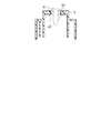
- FIG. 6 is a sectional view taken along line 6-6 of FIG. 4 for explaining the clamp.
- FIG. 7 is a cross-sectional view taken along the line 7-7 of FIG. 4 for explaining the clamp.
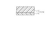
- FIG. 8 is a schematic cross-sectional view of the first tape member.
- FIG. 9 is a schematic cross-sectional view of the second tape member.
- the wire harness of the present disclosure is [1] A wire harness mounted on a vehicle, comprising: an electric wire, a tubular member for accommodating the electric wire, and a clamp for holding the tubular member, and the clamp is the tubular member. It has a main body portion for accommodating the main body portion and a protruding portion protruding from the main body portion in the longitudinal direction of the tubular member, and the tubular member is tightened to the protruding portion by a tightening member.
- the portion includes an inner peripheral surface facing the tubular member, a first end portion of the inner peripheral surface on one side in the circumferential direction, and a second end portion of the inner peripheral surface on the other side in the circumferential direction.
- the inner peripheral surface is a wire harness whose height in the vertical direction is continuously lowered from the first end portion to the second end portion in a state where the wire harness is mounted on the vehicle. ..
- the height of the inner peripheral surface of the protruding portion of the clamp that holds the tubular member is continuously vertical from the first end to the second end in the circumferential direction. Since it is configured to be low, it is possible to suppress the retention of the liquid that tends to stay mainly at the protruding portion of the clamp.
- the main body portion has a tubular portion in which the tubular member is housed and a base portion adjacent to the tubular portion, and the tubular portion communicates the inside and outside of the tubular portion. It is preferable to have a through hole. This is because the liquid to be retained by the clamp can be discharged or ventilated through the through hole of the tubular portion.
- the tubular portion is provided with a plurality of the through holes.
- the plurality of through holes can function as a pair to generate ventilation accompanying the discharge of the liquid, and the discharge of the liquid can be promoted.
- the tubular portion urges an accommodating portion provided with an opening for introducing the tubular member, a lid portion covering the opening, and the tubular member toward the lid portion side.
- the stabilizer portion has a stabilizer portion, and the stabilizer portion is provided by forming the through hole in a U shape. This is because the U-shaped through hole for forming the stabilizer portion can also be used as a discharge hole or a ventilation hole for the liquid to be retained by the clamp.
- the inner peripheral surface is at an intermediate position between the first end portion and the second end portion facing the lowermost portion of the tubular member. It is preferable to have a discharge promoting surface in which the height in the vertical direction is continuously lowered from the intermediate position to the second end portion. This is because the discharge promoting surface allows the liquid on the inner peripheral surface to be discharged more reliably.
- main component includes the meaning of containing other components within a range that does not interfere with the function of the main component, and the content of the main component is 50% by mass, unless otherwise specified. It includes the meaning of occupying the above. That is, additives such as heat stabilizers, antioxidants, ultraviolet absorbers, light stabilizers, crystal nucleating agents, colorants, antistatic agents, hydrolysis inhibitors, lubricants, as long as they do not interfere with the function of the main component. , Flame retardants, elastomers and other various additives may be appropriately contained.
- the wire harness W shown in FIG. 1 is mounted on a vehicle V such as a hybrid vehicle or an electric vehicle.
- the wire harness W includes a high-voltage electric wire 1 that constitutes a high-voltage circuit and a low-voltage electric wire 2 that constitutes a low-voltage circuit.
- the high-voltage power line 1 electrically connects a device M1 such as an inverter mounted on the front portion of the vehicle V and a device M2 such as a high-voltage battery mounted on the rear portion of the vehicle V.
- the inverter is connected to a wheel drive motor that is a power source for vehicle traveling, generates AC power from a high-voltage battery, and supplies the AC power to the motor.
- the high voltage battery is a battery capable of supplying a voltage of, for example, several hundred volts.
- the low-voltage electric wire 2 electrically connects a device M3 such as a fuse box mounted on the front portion of the vehicle V and a device M4 such as a low-voltage battery mounted on the rear portion of the vehicle V.
- the low voltage battery is a battery capable of supplying a voltage of, for example, 12 volts.
- the wire harness W is arranged so as to pass under the floor of the vehicle V, for example.
- Each electric wire 1 and 2 is formed in a long shape so as to extend in the front-rear direction of the vehicle V, for example.
- the high-voltage power line 1 can handle high voltage and large current.
- Each electric wire 1 and 2 has, for example, a core wire formed by twisting a plurality of metal strands and an insulating coating for covering the core wire.
- Each electric wire 1 and 2 may be a shielded electric wire having an electromagnetic shield structure that shields electromagnetic waves, or may be a non-shielded electric wire having no shield structure.
- One end of the high-voltage power line 1 is connected to the device M1 via a connector, and the other end of the high-voltage line 1 is connected to the device M2 via a connector.
- the high-voltage electric wire 1 and the low-voltage electric wire 2 correspond to an example of an electric wire.
- the wire harness W is a high-voltage side pipe 11 that internally accommodates the high-voltage electric wire 1, a low-voltage side pipe 12 that internally accommodates the low-voltage electric wire 2, and one wire harness W that holds both pipes 11 and 12.
- the pipes 11 and 12 is made of metal, and for example, a copper-based or aluminum-based metal material can be used.
- the pipes 11 and 12 serve as a shield structure that protects the electric wires 1 and 2 from flying objects and water droplets and protects the electric wires 1 and 2 from electromagnetic waves.
- the high pressure side pipe 11 has a larger outer diameter than the low pressure side pipe 12.
- the high-voltage electric wire 1 housed inside the high-voltage side pipe 11 tends to have a larger cross-sectional area of the core wire, which is a conductor, in order to suppress heat generation during energization. This is because the outer diameter of the wire tends to be large.
- the high-pressure side pipe 11 and the low-pressure side pipe 12 correspond to an example of the tubular member. After attaching the clamp 10 to each of the pipes 11 and 12, the wire harness W is fixedly routed to a predetermined portion or a wiring path by fixing the clamp 10 to a fixed portion such as a vehicle body.
- the clamp 10 includes a main body 20 for accommodating the pipes 11 and 12, projecting portions 21 and 22 protruding from the main body 20 in the longitudinal direction of the high pressure side pipe 11, and low pressure from the main body 20. It has protruding portions 23 and 24 protruding in the longitudinal direction of the side pipe 12.
- the main body 20 contains a tubular portion 30 in which the high-pressure side pipe 11 is housed, a base portion 40 adjacent to the tubular portion 30, and a low-pressure side pipe 12, and is adjacent to the base portion 40 on the opposite side of the tubular portion 30. It has a tubular portion 50 to be formed.
- the tubular portion 30 urges the accommodating portion 31 provided with the opening 31a for introducing the high-pressure side pipe 11, the lid portion 32 covering the opening portion 31a, and the high-pressure side pipe 11 toward the lid portion 32 side. It has stabilizers 33 and 34 to be used.
- the tubular portion 50 urges the accommodating portion 51 provided with the opening 51a for introducing the low-pressure side pipe 12, the lid portion 52 covering the opening 51a, and the low-pressure side pipe 12 toward the lid portion 52 side. It has stabilizer portions 53 and 54 to be used.
- the stabilizer portions 33 and 34 have a fixed end and a free end along the circumferential direction of the high pressure side pipe 11, and the high pressure side pipe 11 is urged toward the lid portion 32 side on the free end side.
- the stabilizer portion 33 is provided by forming a U-shaped through hole 33a at the lowermost portion of the accommodating portion 31.
- the stabilizer portion 34 is provided by forming a U-shaped through hole 34a at the lowermost portion of the accommodating portion 31.
- the through holes 33a and 34a are provided along the longitudinal direction of the high pressure side pipe 11.
- the inside and outside of the tubular portion 30 are communicated by the through holes 33a and 34a.
- the stabilizer portions 33 and 34 elastically hold the high-pressure side pipe 11 in cooperation with the lid portion 32.
- the through holes 33a and 34a function as discharge holes and ventilation holes for liquids such as water in the tubular portion 30.
- the stabilizer portions 53 and 54 have a fixed end and a free end along the circumferential direction of the low pressure side pipe 12, and the low pressure side pipe 12 is urged toward the lid portion 52 side on the free end side.
- the stabilizer portion 53 is provided by forming a U-shaped through hole 53a at the lowermost portion of the accommodating portion 51.
- the stabilizer portion 54 is provided by forming a U-shaped through hole 54a at the lowermost portion of the accommodating portion 51.
- the through holes 53a and 54a are provided along the longitudinal direction of the low pressure side pipe 12.
- the inside and outside of the tubular portion 50 are communicated by the through holes 53a and 54a.
- the stabilizer portions 53 and 54 elastically hold the low pressure side pipe 12 in cooperation with the lid portion 52.
- the through holes 53a and 54a function as discharge holes and ventilation holes for liquids such as water in the tubular portion 50.
- the projecting portion 21 projects from a portion of the longitudinal end surface of the accommodating portion 31 continuous with the base 40 toward the longitudinal end side of the high pressure side pipe 11.
- the protruding portion 21 has a surface 21x facing the high pressure side pipe 11.
- the surface 21x may be a concave curved surface corresponding to or coincident with the outer peripheral surface of the high-pressure side pipe 11, and may be described as the inner peripheral surface of the protruding portion 21 in the following description.
- the protrusion 21 has a protrusion 21a on the opposite side of the surface 21x facing the high pressure side pipe 11.
- the projecting portion 22 projects from a portion of the other end surface of the accommodating portion 31 in the longitudinal direction continuous with the base 40 toward the other end side of the high pressure side pipe 11 in the longitudinal direction.
- the protruding portion 22 has a surface 22x facing the high pressure side pipe 11.
- the surface 22x may be a concave curved surface corresponding to or coincident with the outer peripheral surface of the high-pressure side pipe 11, and may be described as the inner peripheral surface of the protruding portion 22 in the following description.
- the protrusion 22 has a protrusion 22a on the opposite side of the surface 22x facing the high pressure side pipe 11.
- the projecting portion 23 projects from a portion of the longitudinal end surface of the accommodating portion 51 that is continuous with the base 40 toward the longitudinal end side of the low pressure side pipe 12.
- the protrusion 23 has a surface 23x facing the low pressure side pipe 12.
- the surface 23x may be a concave curved surface corresponding to or coincident with the outer peripheral surface of the low pressure side pipe 12, and may be described as the inner peripheral surface of the protruding portion 23 in the following description.
- the protruding portion 23 has a protruding portion 23a on the opposite side of the surface 23x facing the low pressure side pipe 12.
- the projecting portion 24 projects from a portion of the other end surface of the accommodating portion 51 in the longitudinal direction continuous with the base portion 40 toward the other end side in the longitudinal direction of the low pressure side pipe 12.
- the protrusion 24 has a surface 24x facing the low pressure side pipe 12.
- the surface 24x may be a concave curved surface corresponding to or coincident with the outer peripheral surface of the low pressure side pipe 12, and may be described as the inner peripheral surface of the protruding portion 24 in the following description.
- the protrusion 24 has a protrusion 24a on the opposite side of the surface 24x facing the low pressure side pipe 12.
- the wire harness W has a tape 73 having a surface having a surface that is less slippery to the protrusion 23 than the surface of the low pressure side pipe 12, and a wire harness W that is slippery to the protrusion 24 than the surface of the low pressure side pipe 12. It includes a tape 74 with a small surface. Tapes 73 and 74 are wound around the outer peripheral surface of the low pressure side pipe 12, and the adhesive layer of the tapes 73 and 74 is fixed to the outer peripheral surface of the low pressure side pipe 12, and the surface of the tape 73 and the protruding portion 23 come into contact with each other. At the same time, the surface of the tape 74 and the protruding portion 24 are in contact with each other. As shown in FIG.
- the tape 73 can include a surface layer L1a and an adhesive layer L1b.
- the adhesive layer L1b adheres to or adheres to the outer peripheral surface of the low pressure side pipe 12.
- the surface layer L1a comes into contact with the protrusion 23.
- the surface layer L1a can contain, for example, polyvinyl chloride as a main component.
- the tape 73 is a vinyl tape in which the adhesive layer L1b is integrally provided on one surface of the surface layer L1a.
- the tape 74 can have the same structure as the tape 73, and the surface layer L1a of the tape 74 comes into contact with the protrusion 24.
- the tape 73 and the tape 74 may have another layer between the surface layer L1a and the adhesive layer L1b.
- the wire harness W includes a binding band 63 that presses the tape 73 against the protruding portion 23, and a binding band 64 that presses the tape 74 against the protruding portion 24.
- the low-pressure side pipe 12 is fastened to the protrusions 23 and 24 by using the tapes 73 and 74 and the binding bands 63 and 64 together.
- the tapes 73 and 74 and the binding bands 63 and 64 correspond to an example of a tightening member for fixing the low pressure side pipe 12 to the protrusions 23 and 24.
- the wire harness W includes tapes 71 and 72, which are less elastic than the tapes 73 and 74.
- the high-pressure side pipe 11 is fixed to the protruding portion 21 by winding the tape 71 around the high-pressure side pipe 11 and the protruding portion 21 and fixing the tape 71 with the adhesive layer of the tape 71.
- the high pressure side pipe 11 is fixed to the protruding portion 22 by winding the tape 72 around the high pressure side pipe 11 and the protruding portion 22 and fixing the tape 72 with the adhesive layer of the tape 72.
- the tape 71 can include a cloth layer L2a and an adhesive layer L2b.
- the adhesive layer L2b adheres to or adheres to the outer peripheral surface of the high-pressure side pipe 11 and the outer peripheral surface of the protruding portion 21.
- the cloth layer L2a can contain, for example, acetate fibers as a main component.
- the tape 71 is, for example, an acetate tape in which the adhesive layer L2b is integrally provided on one surface of the cloth layer L2a.
- the tape 72 can have the same structure as the tape 71, and the adhesive layer L2b of the tape 72 adheres or adheres to the outer peripheral surface of the high-pressure side pipe 11 and the outer peripheral surface of the protruding portion 22.
- the tape 71 and the tape 72 may have another layer between the cloth layer L2a and the adhesive layer L2b, or may have another layer on the opposite side of the cloth layer L2a from the adhesive layer L2b. May be good.
- the tapes 71 and 72 are not limited to acetate tapes, and the cloth layer L2a of the tapes 71 and 72 may be a cloth layer containing other fibers as a main component, for example, polyester fibers.
- the wire harness W includes a binding band 61 for tightening the tape 71 and a binding band 62 for tightening the tape 72.
- the high-pressure side pipe 11 is fastened to the protrusions 21 and 22 by using the tapes 71 and 72 and the binding bands 61 and 62 together.
- the tapes 71 and 72 and the binding bands 61 and 62 correspond to an example of a tightening member for fixing the high pressure side pipe 11 to the protrusions 21 and 22.
- the projecting portions 21 and 22 have inner peripheral surfaces 21x and 22x facing the high-pressure side pipe 11 and first end portions P1 on one side of the inner peripheral surfaces 21x and 22x in the circumferential direction. And a second end P3 on the other side in the circumferential direction.
- the heights of the inner peripheral surfaces 21x and 22x of the protrusions 21 and 22 are continuously vertical from the first end P1 to the second end P3. It is formed to be low.
- the first end P1 is in the front view at about 3 o'clock of the clock
- the second end P3 is in the front view at about 3:1 past the clock at 6 o'clock in the clockwise direction. is there.
- the inner peripheral surfaces 21x and 22x of the protruding portions 21 and 22 are high-pressure side pipes between the first end portion P1 and the second end portion P3. It has an intermediate position P2 facing the bottom of 11.
- the intermediate position P2 is the direction of about 6 o'clock of the clock when viewed from the front.
- the region R12 from the first end portion P1 to the intermediate position P2 is formed by an arc corresponding to the outer circumference of the high pressure side pipe 11.
- the region R23 from the intermediate position P2 to the second end P3 has a height in the vertical direction from the intermediate position P2 to the second end P3. It is formed by emission promoting surfaces 21y and 22y that are continuously lowered.
- the region R23 which is the discharge promoting surfaces 21y and 22y, is a slope whose height in the vertical direction is linearly lowered, a curved surface whose height in the vertical direction is lowered in a quadratic curve, or slopes having different slopes or different. It may be formed by either curved surfaces having curvature or a combination of a slope and a curved surface. Further, the region R23 of the protruding portion 21 and the region R23 of the protruding portion 22 may be formed by different discharge promoting surfaces 21y and 22y.
- the protruding portions 23 and 24 have inner peripheral surfaces 23x and 24x facing the low pressure side pipe 12, a first end portion P4, and a second end portion P6.
- the heights of the inner peripheral surfaces 23x and 24x of the protruding portions 23 and 24 are continuously vertical from the first end portion P4 to the second end portion P6. It is formed to be low.
- the first end P4 is the direction of about 9 o'clock in the front view of the clock
- the second end P6 is the direction of about 5:30 in the front view past 6 o'clock of the clock in the counterclockwise direction. Is.
- the inner peripheral surfaces 23x and 24x of the protruding portions 23 and 24 are low-pressure side pipes between the first end portion P4 and the second end portion P6. It has an intermediate position P5 facing the bottom of the twelve.
- the intermediate position P5 is the direction of about 6 o'clock of the clock when viewed from the front.
- the region R45 from the first end portion P4 to the intermediate position P5 is formed by an arc corresponding to the outer circumference of the low pressure side pipe 12.
- the region R56 from the intermediate position P5 to the second end P6 has a height in the vertical direction from the intermediate position P5 to the second end P6. It is formed by emission promoting surfaces 23y and 24y that are continuously lowered.
- the region R56 of the discharge promotion surfaces 23y and 24y is a slope whose height in the vertical direction is linearly lowered, a curved surface whose height in the vertical direction is lowered in a quadratic curve, or slopes having different slopes or different. It may be formed by either curved surfaces having curvature or a combination of a slope and a curved surface. Further, the region R56 of the protruding portion 23 and the region R56 of the protruding portion 24 may be formed by different discharge promoting surfaces 23y and 24y.
- a predetermined portion of the high-pressure side pipe 11 intersects the longitudinal direction of the high-pressure side pipe 11 from a lateral direction that can be in the radial direction through the opening 31a. Is introduced into the accommodation unit 31. Then, for example, the lid portion 32 is locked to the accommodating portion 31 by a snap-fit structure. At this time, the high-pressure side pipe 11 is elastically held by the stabilizer portions 33 and 34 (see FIG. 6).
- the tape 71 is wound around the high-pressure side pipe 11 and the protruding portion 21, the high-pressure side pipe 11 is fixed to the protruding portion 21, and the binding band 61 is further tightened from above the tape 71.
- the tape 72 is wound around the high-pressure side pipe 11 and the protruding portion 22, the high-pressure side pipe 11 is fixed to the protruding portion 22, and the binding band 62 is further tightened from above the tape 72.
- the tapes 73 and 74 are wound and fixed in advance around the predetermined portion of the low pressure side pipe 12.
- a predetermined portion of the low-pressure pipe 12 around which the tapes 73 and 74 are wound may be referred to as a taping region.
- the low pressure side pipe 12 is moved in the longitudinal direction of the low pressure side pipe 12. It is introduced into the accommodating portion 51 through the opening 51a from the lateral direction which intersects and may be the radial direction. Then, for example, the lid portion 52 is locked to the accommodating portion 51 by a snap-fit structure.
- the low pressure side pipe 12 is elastically held by the stabilizer portions 53 and 54 (see FIG. 6).
- the protrusion 23 and the low-pressure side pipe 12 are fastened together by the binding band 63 in the tape 73 portion so as to press the tape 73 against the protrusion 23.
- the protrusion 24 and the low pressure side pipe 12 are jointly fastened with the binding band 64 in the tape 74 portion so as to press the tape 74 against the protrusion 24.
- the clamp 10 is fixed to the fixed portion of the vehicle body or the like by fastening the bolt 81 and the nut 82 via the collar 80 provided on the clamp 10.
- the wire harness W is mounted on the vehicle V.
- the inner peripheral surfaces 21x to 24x of the protruding portions 21 to 24 are in the vertical direction from the first ends P1 and P4 to the second ends P3 and P6.
- the liquid such as water is preferably discharged along the inner peripheral surfaces 21x to 24x of the protruding portions 21 to 24. Further, since the through holes 33a, 34a, 53a, 54a function as discharge holes and ventilation holes for a liquid such as water, the discharge property of the liquid from the clamp 10 is enhanced.
- the following actions and effects can be obtained.
- the inner peripheral surfaces 21x to 24x of the protrusions 21 to 24 of the clamp 10 holding the high pressure side pipe 11 and the low pressure side pipe 12 are the first in the circumferential direction.
- the clamp 10 mainly the protrusions 21 to 24
- the effect of discharging liquids such as water can be obtained. Therefore, the retention of the liquid in the clamp 10 can be suppressed.
- each of the pipes 11 and 12 is made of metal, it is possible to reduce the situation where the pipes are continuously exposed to the liquid for a long time and suppress the occurrence of corrosion and the like.
- the U-shaped through holes 33a, 34a, 53a, 54a for forming the stabilizer portions 33, 53 are formed in the clamp 10 (mainly the tubular portions 30, 50) and the discharge holes for the liquid to be retained. It can also be used as a ventilation hole.
- the above embodiment can be modified and implemented as follows.
- the above embodiment and the following modified examples can be combined and implemented within a technically consistent range.
- the wire harness W may be a wire harness W including a clamp 10 for holding one or three or more tubular members (for example, a high-pressure side pipe 11).
- the tightening member is not limited to both the tape member (for example, tapes 71 to 74) and the band member (for example, binding bands 61 to 64), and may be one of them or a member different from them.
- -One of the protrusions 21 and 22 and one of the protrusions 23 and 24 may be omitted.
- -One of the stabilizer portions 33 and 34 and one of the stabilizer portions 53 and 54 may be omitted.
- one stabilizer portion may be provided at the center of the tubular portions 30 and 50 in the longitudinal direction.
- the inner peripheral surfaces 21x to 24x of the protrusions 21 to 24 are not limited to being formed only by a curved surface, and may be formed only by a flat surface or by a combination of a flat surface and a curved surface. .. However, in a state where the wire harness W is mounted on the vehicle V, the inner peripheral surfaces 21x to 24x of the protruding portions 21 to 24 are in the vertical direction from the first ends P1 and P4 to the second ends P3 and P6. It is formed so that the height is continuously lowered.
- -Through holes 33a, 34a, 53a, 54a are not limited to the lowermost portions of the accommodating portions 31, 51, but may be provided at other locations as long as they communicate with each other inside and outside the tubular portions 30, 50. ..
- the through holes 33a, 34a, 53a, 54a can function as liquid discharge holes and ventilation holes.
- the through holes 33a, 34a, 53a, 54a function as ventilation holes. Can be made to.
- the tubular portion 30 is provided with two through holes 33a and 34a, but one of the through holes 33a and 34a may be omitted. Similarly, one of the through holes 53a and 54a may be omitted.
- the through holes 33a, 34a, 53a, 54a may be omitted.
- the stabilizer portions 33, 34, 53, 54 are provided by forming the U-shaped through holes 33a, 34a, 53a, 54a, the through holes 33a, 34a, 53a, 54a are provided. You may.
- the inner peripheral surfaces 21x and 22x of the protrusions 21 and 22 are such that the first end P1 is in the front view at about 3 o'clock and the second end P3 is in the front view at about 6:30.
- the configuration is not limited to the direction of.
- the first end P4 is in the front view at about 9 o'clock of the clock
- the second end P6 is in the front view at about 5 o'clock of the clock.
- the configuration is not limited to the half direction.
- the inner peripheral surfaces 21x to 24x of the protrusions 21 to 24 are viewed from the short hand position at 10:45 in the front view (corresponding to an example of the first end) at 7:15 in the counterclockwise direction. It may be formed so that the height in the vertical direction is continuously lowered to the position of the short hand (corresponding to an example of the second end).
- each pipe 11 and 12 can have a linear portion and may further have a bent portion.
- the pipes 11 and 12 are typically cylindrical and may be non-cylindrical, such as an elliptical cylinder.
- the clamp 10 is attached to the linear portion of the pipes 11 and 12, bridges the linear portion of the pipe 11 and the linear portion of the pipe 12, and defines the linear portion of the pipe 11 and the linear portion of the pipe 12. It is configured to be held apart at a distance.
- the clamp 10 is configured to keep the linear portion of the pipe 11 and the linear portion of the pipe 12 substantially parallel to each other.
- the linear portion of the clamp 10 and the pipe 11 and the linear portion of the pipe 12 can be arranged or extend in the same plane, for example.
- the clamp 10 is advantageous in lowering the profile such as thinning the wire harness W having a plurality of pipes.
- the accommodating portions 31, 51 of the clamp 10 may have concave curved surfaces that correspond to or match the outer peripheral surfaces of the corresponding pipes 11, 11.
- the protrusion 23 of the clamp 10 may be a tongue-shaped protrusion having a concave curved surface that corresponds to or matches the outer peripheral surface of the corresponding pipe 12.
- the protruding portion 23 may have a convex curved surface on the opposite side of the concave curved surface. The same applies to the other protrusions 21, 22, and 24.
- the discharge promoting surface 21y of the protruding portion 21 of the clamp 10 can be configured as a chamfered or beveled edge provided in the vicinity of the second end P3 of the protruding portion 21.
- the liquid on the inner peripheral surface 21x of the protruding portion 21 may stay in the vicinity of the second end P3 of the inner peripheral surface 21x due to the surface tension of the liquid.
- the discharge promoting surface 21y which is a chamfered edge provided in the vicinity of the second end P3, does not allow the liquid to stay in the vicinity of the second end P3.
- the flow of the liquid further progresses on the discharge promoting surface 21y due to the weight of the liquid, and the liquid smoothly moves beyond the second end P3 of the protrusion 21 to the lower surface side which is the convex curved surface of the protrusion 21. Then, the liquid is discharged from the second end P3 of the protrusion 21 or from the lower surface side thereof by hanging or dropping.
- the discharge promoting surface 21y prevents or reduces the retention of the liquid due to surface tension in the vicinity of the second end P3 of the inner peripheral surface 21x of the protruding portion 21. The same applies to the other emission promoting surfaces 22y to 24y.
- the protrusion 23a may be referred to as a tightening member stopper configured to prevent the binding band 63 from falling off from the protrusion 23.
- the protrusion 21a is referred to as a tape stopper configured to suppress the displacement of the tape 71 with respect to the protrusion 21 or to prevent the tape 71 from partially or wholly falling off from the protrusion 21. I have something to do. The same applies to the protrusion 22a.
- the stabilizer portion 33 can be configured to elastically support the corresponding pipe 11 from below, for example.
- the stabilizer portion 33 is advantageous for absorbing the vibration of the pipe 11 caused by, for example, traveling of the vehicle.
- the stabilizer portion 33 can be configured as a cantilever plate-shaped damper integrally formed with the tubular portion 30 of the clamp 10. The same applies to the stabilizer portions 34 of the tubular portion 30 and the stabilizer portions 53 and 54 of the tubular portion 50.
- the clamp 10 can be configured as a one-piece product made of synthetic resin.
- the clamp 10 may be configured as an assembly of a plurality of parts.
- the present disclosure includes the following implementation examples. Reference symbols have been added to the components of the embodiments not for limitation but as an aid to understanding.
- a wire harness is Electric wire (1) and A tubular member (11) having an outer peripheral surface and a linear portion and accommodating the electric wire (1) inside, A clamp (10) for holding the linear portion of the tubular member (11) can be provided.
- the clamp (10) has a mounting surface (80) configured to be fixedly mounted on the vehicle.
- the clamp (10) can have a concave curved surface (31a, 51a, 21x, 22x, 23x, 24x) that corresponds to or matches the outer peripheral surface of the tubular member (11).
- the predetermined positions (33a, 34a, P3, P6) of the concave curved surface (31a, 51a, 21x, 22x, 23x, 24x) are the concave curved surface (31a). , 51a, 21x, 22x, 23x, 24x), located at the lowest position in the vertical direction.
- the clamp (10) is placed at the predetermined position (33a, 34a, P3, P6) of the concave curved surface (31a, 51a, 21x, 22x, 23x, 24x), and the concave curved surface (31a, 51a, 21x, 22x, It can have drainage promotion structures (33a, 34a, 21y, 22y, 23y, 24y) configured to promote drainage from 23x, 24x).
- the clamp (10) can have tongue-shaped protrusions (21, 22, 23, 24) protruding in the longitudinal direction of the tubular member (11), and the tongue-shaped protrusions (21, 22). , 23, 24) can have concave curved surfaces (21x, 22x, 23x, 24x) that correspond to the outer peripheral surface of the tubular member (11, 12).
- the drainage promotion structure (33a, 34a, 21y, 22y, 23y, 24y) is a chamfered edge provided near the edge of the concave curved surface (21x, 22x, 23x, 24x) of the tongue-shaped protrusion (21). (21y, 22y, 23y, 24y) can be included.
- the clamp (10) is configured to be attached to the tubular member (11, 12) from the lateral direction intersecting the longitudinal direction of the tubular member (11, 12).
- , 51) and the accommodating portion (31, 51) can have a concave curved surface that matches the outer peripheral surface of the tubular member (11, 12).
- the drainage promotion structure (33a, 34a, 21y, 22y, 23y, 24y) is provided on the concave curved surface of the accommodating portion (31, 51) and has a slit shape penetrating the lowest position in the vertical direction of the concave curved surface.
- Drainage holes (33a, 34a) can be included,
- the clamp (10) can include a cantilever plate-shaped damper (33, 34) configured to elastically press the outer peripheral surface of the tubular member (11, 12), and the piece.
- the holding plate-shaped damper (33, 34) has the slit-shaped drain hole (33a, 34a) penetrating the concave curved surface of the accommodating portion (31, 51) so that the accommodating portion (31, 51) is vertical. It can be partitioned at the lowest position in the direction.
Landscapes
- Engineering & Computer Science (AREA)
- Mechanical Engineering (AREA)
- General Engineering & Computer Science (AREA)
- Architecture (AREA)
- Civil Engineering (AREA)
- Structural Engineering (AREA)
- Installation Of Indoor Wiring (AREA)
- Details Of Indoor Wiring (AREA)
- Insulated Conductors (AREA)
- Clamps And Clips (AREA)
Abstract
筒状部材を保持するクランプでの液体の滞留を抑制することができるワイヤハーネスを提供する。ワイヤハーネスは、電線と、電線を内部に収容するパイプと、パイプを保持するクランプとを備える。クランプは、パイプを収容する本体部と、本体部からパイプの長手方向に突出した突出部21~24とを有し、突出部21~24に対してパイプがテープや結束バンド等を用いて固定される。突出部21~24は、パイプと対向する内周面21x~24xと、周方向一方側の第1の端部P1、P4と、周方向他方側の第2の端部P3、P6とを有する。ワイヤハーネスが車両に搭載された状態において、突出部21~24の内周面21x~24xは、第1の端部P1、P4から第2の端部P3、P6まで鉛直方向の高さが連続的に低くなる。
Description
本開示は、ワイヤハーネスに関する。
特許文献1には、電線が内部に収容された金属製のパイプ等の筒状部材を保持して車体に固定されるクランプを備えるワイヤハーネスが記載されている。
筒状部材を保持するクランプにおいて水等の液体の排出構造を持ち合わせていないものでは、そのクランプに水等の液体が滞留すると筒状部材が長時間液体にさらされ続ける状況が生じ、金属製のパイプ等では腐食等の発生が懸念される。
そこで、筒状部材を保持するクランプでの液体の滞留を抑制することができるワイヤハーネスを提供することを目的とする。
本開示のワイヤハーネスは、車両に搭載されるワイヤハーネスであって、電線と、前記電線を内部に収容する筒状部材と、前記筒状部材を保持するクランプと、を備え、前記クランプは、前記筒状部材を収容する本体部と、前記本体部から前記筒状部材の長手方向に突出した突出部と、を有し、前記突出部は、前記筒状部材と対向する内周面と、第1の端部と、第2の端部と、を有し、前記筒状部材は、締付け部材によって前記突出部に締付けられており、前記ワイヤハーネスが前記車両に搭載された状態において、前記内周面は、前記第1の端部から前記第2の端部まで鉛直方向の高さが連続的に低くなるワイヤハーネスである。
本開示によれば、筒状部材を保持するクランプでの液体の滞留を抑制することができるワイヤハーネスを提供することが可能となる。
[本開示の実施形態の説明]
最初に本開示の実施形態を列記して説明する。
本開示のワイヤハーネスは、
[1]車両に搭載されるワイヤハーネスであって、電線と、前記電線を内部に収容する筒状部材と、前記筒状部材を保持するクランプと、を備え、前記クランプは、前記筒状部材を収容する本体部と、前記本体部から前記筒状部材の長手方向に突出した突出部と、を有し、前記突出部に対して前記筒状部材が締付け部材によって締付けられており、前記突出部は、前記筒状部材と対向する内周面と、前記内周面の周方向一方側の第1の端部と、前記内周面の周方向他方側の第2の端部と、を有し、ワイヤハーネスが前記車両に搭載された状態において、前記内周面は、前記第1の端部から前記第2の端部まで鉛直方向の高さが連続的に低くなるワイヤハーネスである。
最初に本開示の実施形態を列記して説明する。
本開示のワイヤハーネスは、
[1]車両に搭載されるワイヤハーネスであって、電線と、前記電線を内部に収容する筒状部材と、前記筒状部材を保持するクランプと、を備え、前記クランプは、前記筒状部材を収容する本体部と、前記本体部から前記筒状部材の長手方向に突出した突出部と、を有し、前記突出部に対して前記筒状部材が締付け部材によって締付けられており、前記突出部は、前記筒状部材と対向する内周面と、前記内周面の周方向一方側の第1の端部と、前記内周面の周方向他方側の第2の端部と、を有し、ワイヤハーネスが前記車両に搭載された状態において、前記内周面は、前記第1の端部から前記第2の端部まで鉛直方向の高さが連続的に低くなるワイヤハーネスである。
ワイヤハーネスが車両に搭載された状態において、筒状部材を保持するクランプの突出部の内周面が周方向の第1の端部から第2の端部まで鉛直方向の高さが連続的に低くなるように構成されているため、クランプの主として突出部にて滞留しようとする液体の滞留を抑制することが可能となる。
[2]前記本体部は、前記筒状部材が収容される筒状部と、前記筒状部と隣接する基部と、を有し、前記筒状部は、該筒状部の内外を連通させる貫通孔を有することが好ましい。筒状部の貫通孔を通じてクランプにて滞留しようとする液体の排出や通気を行うことができるからである。
[3]前記筒状部には、前記貫通孔が複数設けられていると良い。筒状部に複数の貫通孔が設けられることで、クランプにて滞留しようとする液体の排出機会が増える。また、複数の貫通孔が対で機能して液体の排出に伴う通気を生じさせることも可能となり、その液体の排出を促進することができるからである。
[4]前記筒状部は、前記筒状部材を導入する開口部が設けられた収容部と、前記開口部を覆う蓋部と、前記筒状部材を前記蓋部側に向かって付勢するスタビライザ部と、を有し、前記スタビライザ部は、前記貫通孔がU字状に形成されることで設けられると良い。スタビライザ部を形成するためのU字状の貫通孔は、クランプにて滞留しようとする液体の排出孔や通気孔として兼用することができるからである。
[5]ワイヤハーネスが前記車両に搭載された状態において、前記内周面は、前記第1の端部と前記第2の端部との間に前記筒状部材の最下部と対向する中間位置を有し、前記中間位置から前記第2の端部まで鉛直方向の高さが連続的に低くなる排出促進面を有すると良い。排出促進面によって内周面にある液体をより確実に排出することができるからである。
[本開示の実施形態の詳細]
本開示のワイヤハーネスの具体例を、以下に図面を参照しつつ説明する。本開示において、「主成分」と表現した場合には、特に記載しない限り、当該主成分の機能を妨げない範囲で他の成分を含有する意を包含し、主成分の含有量は50質量%以上を占める意を包含するものである。すなわち、当該主成分の機能を妨げない範囲で添加剤、例えば、熱安定剤、酸化防止剤、紫外線吸収剤、光安定剤、結晶核剤、着色剤、帯電防止剤、加水分解防止剤、滑剤、難燃剤、エラストマーなどの各種添加剤が適宜含まれていてもよい。また、主成分の機能を妨げない範囲で他の樹脂組成物が含まれていてもよい。なお、本発明はこれらの例示に限定されるものではなく、特許請求の範囲によって示され、特許請求の範囲と均等の意味および範囲内でのすべての変更が含まれることが意図される。各図面では、説明の便宜上、構成の一部を誇張又は簡略化して示す場合がある。また、各部分の寸法比率についても、実際とは異なる場合がある。
本開示のワイヤハーネスの具体例を、以下に図面を参照しつつ説明する。本開示において、「主成分」と表現した場合には、特に記載しない限り、当該主成分の機能を妨げない範囲で他の成分を含有する意を包含し、主成分の含有量は50質量%以上を占める意を包含するものである。すなわち、当該主成分の機能を妨げない範囲で添加剤、例えば、熱安定剤、酸化防止剤、紫外線吸収剤、光安定剤、結晶核剤、着色剤、帯電防止剤、加水分解防止剤、滑剤、難燃剤、エラストマーなどの各種添加剤が適宜含まれていてもよい。また、主成分の機能を妨げない範囲で他の樹脂組成物が含まれていてもよい。なお、本発明はこれらの例示に限定されるものではなく、特許請求の範囲によって示され、特許請求の範囲と均等の意味および範囲内でのすべての変更が含まれることが意図される。各図面では、説明の便宜上、構成の一部を誇張又は簡略化して示す場合がある。また、各部分の寸法比率についても、実際とは異なる場合がある。
図1に示すワイヤハーネスWは、ハイブリッド車や電気自動車等の車両Vに搭載されるものである。ワイヤハーネスWは、高圧回路を構成する高圧電線1と、低圧回路を構成する低圧電線2とを備えている。高圧電線1は、車両Vの前部に搭載されたインバータ等の機器M1と、車両Vの後部に搭載された高圧バッテリ等の機器M2とを電気的に接続する。インバータは、車両走行の動力源となる車輪駆動用のモータと接続され、高圧バッテリから交流電力を生成し、その交流電力をモータに供給する。高圧バッテリは、例えば数百ボルトの電圧を供給可能なバッテリである。低圧電線2は、車両Vの前部に搭載されたヒューズボックス等の機器M3と、車両Vの後部に搭載された低圧バッテリ等の機器M4とを電気的に接続する。低圧バッテリは、例えば12ボルトの電圧を供給可能なバッテリである。ワイヤハーネスWは、例えば車両Vの床下等を通るように配索される。
各電線1、2は、例えば車両Vの前後方向に延びるように長尺状に形成されている。高圧電線1は、高電圧・大電流に対応可能である。各電線1、2は、例えば複数の金属素線を撚り合わせてなる芯線と、その芯線を被覆する絶縁被覆とを有している。各電線1、2は、電磁波をシールドする電磁シールド構造を有するシールド電線であってもよいし、シールド構造を有さないノンシールド電線であってもよい。高圧電線1の一端部はコネクタを介して機器M1と接続され、高圧電線1の他端部はコネクタを介して機器M2と接続されている。低圧電線2の一端部は端子金具を介して機器M3と接続され、低圧電線2の他端部は端子金具を介して機器M4と接続されている。高圧電線1や低圧電線2が電線の一例に相当する。
図2に示すように、ワイヤハーネスWは、高圧電線1を内部に収容する高圧側パイプ11と、低圧電線2を内部に収容する低圧側パイプ12と、両パイプ11、12を保持する1個又は2個以上のクランプ10とを備えている。各パイプ11、12は金属製であり、例えば銅系やアルミニウム系の金属材料を用いることができる。各パイプ11、12は、飛翔物や水滴から各電線1、2を保護するとともに、各電線1、2を電磁波から保護するシールド構造の役目を果たす。図5及び図6に示すように、高圧側パイプ11は、低圧側パイプ12よりも外径が大きい。この理由は、高圧側パイプ11の内部に収容される高圧電線1は、通電時の発熱を抑制するために導体である芯線の断面積が大きくなる傾向があるため、低圧電線2と比べて電線の外径が大きくなる傾向にあるためである。高圧側パイプ11や低圧側パイプ12が筒状部材の一例に相当する。ワイヤハーネスWは、各パイプ11、12にクランプ10を取り付けた後、クランプ10を車体等の被固定部に固定することにより、所定の部位または配索経路に固定的に配索される。
図3に示すように、クランプ10は、各パイプ11、12を収容する本体部20と、本体部20から高圧側パイプ11の長手方向に突出した突出部21、22と、本体部20から低圧側パイプ12の長手方向に突出した突出部23、24とを有している。本体部20は、高圧側パイプ11が収容される筒状部30と、筒状部30と隣接する基部40と、低圧側パイプ12が収容され、筒状部30の反対側で基部40と隣接する筒状部50とを有している。筒状部30は、高圧側パイプ11を導入する開口部31aが設けられた収容部31と、該開口部31aを覆う蓋部32と、高圧側パイプ11を蓋部32側に向かって付勢するスタビライザ部33、34とを有している。筒状部50は、低圧側パイプ12を導入する開口部51aが設けられた収容部51と、該開口部51aを覆う蓋部52と、低圧側パイプ12を蓋部52側に向かって付勢するスタビライザ部53、54とを有している。
スタビライザ部33、34は、高圧側パイプ11の周方向に沿って固定端と自由端とを有し、その自由端側で高圧側パイプ11を蓋部32側に向かって付勢する。スタビライザ部33は、収容部31の最下部にU字状の貫通孔33aが形成されることで設けられる。同様に、スタビライザ部34は、収容部31の最下部にU字状の貫通孔34aが形成されることで設けられる。貫通孔33a、34aは、高圧側パイプ11の長手方向に沿って設けられている。貫通孔33a、34aによって筒状部30の内外が連通されている。スタビライザ部33、34は、蓋部32と協働して高圧側パイプ11を弾性的に保持する。貫通孔33a、34aは、筒状部30における水等の液体の排出孔や通気孔として機能する。
スタビライザ部53、54は、低圧側パイプ12の周方向に沿って固定端と自由端とを有し、その自由端側で低圧側パイプ12を蓋部52側に向かって付勢する。スタビライザ部53は、収容部51の最下部にU字状の貫通孔53aが形成されることで設けられる。同様に、スタビライザ部54は、収容部51の最下部にU字状の貫通孔54aが形成されることで設けられる。貫通孔53a、54aは、低圧側パイプ12の長手方向に沿って設けられている。貫通孔53a、54aによって筒状部50の内外が連通されている。スタビライザ部53、54は、蓋部52と協働して低圧側パイプ12を弾性的に保持する。貫通孔53a、54aは、筒状部50における水等の液体の排出孔や通気孔として機能する。
突出部21は、収容部31の長手方向一端面のうち基部40に連続する箇所から高圧側パイプ11の長手方向一端側に向かって突出される。突出部21は、高圧側パイプ11と対向する面21xを有している。この面21xは、高圧側パイプ11の外周面に対応するまたは一致する凹曲面であってよく、以下の説明では突出部21の内周面と記述することがある。突出部21は、高圧側パイプ11と対向する面21xの反対側に突起部21aを有している。突出部22は、収容部31の長手方向他端面のうち基部40に連続する箇所から高圧側パイプ11の長手方向他端側に向かって突出される。突出部22は、高圧側パイプ11と対向する面22xを有している。この面22xは、高圧側パイプ11の外周面に対応するまたは一致する凹曲面であってよく、以下の説明では突出部22の内周面と記述することがある。突出部22は、高圧側パイプ11と対向する面22xの反対側に突起部22aを有している。
突出部23は、収容部51の長手方向一端面のうち基部40に連続する箇所から低圧側パイプ12の長手方向一端側に向かって突出される。突出部23は、低圧側パイプ12と対向する面23xを有している。この面23xは、低圧側パイプ12の外周面に対応するまたは一致する凹曲面であってよく、以下の説明では突出部23の内周面と記述することがある。突出部23は、低圧側パイプ12と対向する面23xの反対側に突起部23aを有している。突出部24は、収容部51の長手方向他端面のうち基部40に連続する箇所から低圧側パイプ12の長手方向他端側に向かって突出される。突出部24は、低圧側パイプ12と対向する面24xを有している。この面24xは、低圧側パイプ12の外周面に対応するまたは一致する凹曲面であってよく、以下の説明では突出部24の内周面と記述することがある。突出部24は、低圧側パイプ12と対向する面24xの反対側に突起部24aを有している。
図2を参照して、ワイヤハーネスWは、低圧側パイプ12の表面よりも突出部23に対する滑り性の小さい表面を有するテープ73と、低圧側パイプ12の表面よりも突出部24に対する滑り性の小さい表面を有するテープ74とを備えている。低圧側パイプ12の外周面にはテープ73、74が巻かれてテープ73、74の粘着層が低圧側パイプ12の外周面に固定されており、テープ73の表面と突出部23とが接触しているとともに、テープ74の表面と突出部24とが接触している。図8に示すように、テープ73は、表層L1aと粘着層L1bとを含むことができる。粘着層L1bは、低圧側パイプ12の外周面に粘着または接着する。表層L1aは、突出部23と接触する。表層L1aは、例えばポリ塩化ビニルを主成分とすることができる。図示した例では、テープ73は、表層L1aの一面に粘着層L1bが一体的に設けられてなるビニルテープである。テープ74はテープ73と同じ構造を有することができ、テープ74の表層L1aは突出部24と接触する。なお、テープ73とテープ74は、表層L1aと粘着層L1bとの間に他の層を有していてもよい。また、ワイヤハーネスWは、テープ73を突出部23へ押し付ける結束バンド63と、テープ74を突出部24へ押し付ける結束バンド64とを備えている。低圧側パイプ12は、テープ73、74と結束バンド63、64とが併用されることによって突出部23、24に締付けられている。テープ73、74や結束バンド63、64が、低圧側パイプ12を突出部23、24に固定するための締付け部材の一例に相当する。
また、ワイヤハーネスWは、テープ73、74と比べて伸縮性が小さいテープ71、72を備えている。高圧側パイプ11と突出部21とにテープ71が巻かれてテープ71の粘着層にて固定されることで、高圧側パイプ11が突出部21に対して固定されている。また、高圧側パイプ11と突出部22とにテープ72が巻かれてテープ72の粘着層にて固定されることで、高圧側パイプ11が突出部22に対して固定されている。図9に示すように、テープ71は、布層L2aと粘着層L2bとを含むことができる。粘着層L2bは、高圧側パイプ11の外周面と突出部21の外周面とに粘着または接着する。布層L2aは、例えばアセテート繊維を主成分とすることができる。図示した例では、テープ71、は、例えば布層L2aの一面に粘着層L2bが一体的に設けられてなるアセテートテープである。テープ72はテープ71と同じ構造を有することができ、テープ72の粘着層L2bは、高圧側パイプ11の外周面と突出部22の外周面とに粘着または接着する。テープ71とテープ72は、布層L2aと粘着層L2bとの間に他の層を有していてもよいし、布層L2aの粘着層L2bとは反対側に他の層を有していてもよい。テープ71、72は、アセテートテープに限定されず、テープ71、72の布層L2aは、例えばポリエステル系繊維等の他の繊維を主成分とする布層であってもよい。また、ワイヤハーネスWは、テープ71を締付ける結束バンド61と、テープ72を締付ける結束バンド62とを備えている。高圧側パイプ11は、テープ71、72と結束バンド61、62とが併用されることによって突出部21、22に締付けられている。テープ71、72や結束バンド61、62が、高圧側パイプ11を突出部21、22に固定するための締付け部材の一例に相当する。
図4及び図5に示すように、突出部21、22は、高圧側パイプ11と対向する内周面21x、22xと、内周面21x、22xの周方向一方側の第1の端部P1と、その周方向他方側の第2の端部P3とを有している。ワイヤハーネスWが車両Vに搭載された状態において、突出部21、22の内周面21x、22xは、第1の端部P1から第2の端部P3まで鉛直方向の高さが連続的に低くなるように形成されている。第1の端部P1は、正面視で時計の約3時の方向であり、第2の端部P3は、正面視で時計の6時を時計回り方向に過ぎた約6時半の方向である。また、ワイヤハーネスWが車両Vに搭載された状態において、突出部21、22の内周面21x、22xは、第1の端部P1と第2の端部P3との間に、高圧側パイプ11の最下部と対向する中間位置P2を有している。中間位置P2は、正面視で時計の約6時の方向である。
突出部21、22の内周面21x、22xのうち、第1の端部P1から中間位置P2までの領域R12は、高圧側パイプ11の外周に対応する円弧によって形成されている。一方、突出部21、22の内周面21x、22xのうち、中間位置P2から第2の端部P3までの領域R23は、中間位置P2から第2の端部P3まで鉛直方向の高さが連続的に低くなる排出促進面21y、22yによって形成されている。排出促進面21y、22yである領域R23は、鉛直方向の高さが線形に低くなる斜面、又は鉛直方向の高さが例えば二次曲線的に低くなる曲面、又は異なる傾きを持つ斜面同士若しくは異なる曲率を持つ曲面同士若しくは斜面と曲面との組み合わせのいずれによって形成されていてもよい。また、突出部21の領域R23と突出部22の領域R23とは、互いに異なる排出促進面21y、22yによって形成されていてもよい。
同様に、突出部23、24は、低圧側パイプ12と対向する内周面23x、24xと、第1の端部P4と、第2の端部P6とを有している。ワイヤハーネスWが車両Vに搭載された状態において、突出部23、24の内周面23x、24xは、第1の端部P4から第2の端部P6まで鉛直方向の高さが連続的に低くなるように形成されている。第1の端部P4は、正面視で時計の約9時の方向であり、第2の端部P6は、正面視で時計の6時を反時計回り方向に過ぎた約5時半の方向である。また、ワイヤハーネスWが車両Vに搭載された状態において、突出部23、24の内周面23x、24xは、第1の端部P4と第2の端部P6との間に、低圧側パイプ12の最下部と対向する中間位置P5を有している。中間位置P5は、正面視で時計の約6時の方向である。
突出部23、24の内周面23x、24xのうち、第1の端部P4から中間位置P5までの領域R45は、低圧側パイプ12の外周に対応する円弧によって形成されている。一方、突出部23、24の内周面23x、24xのうち、中間位置P5から第2の端部P6までの領域R56は、中間位置P5から第2の端部P6まで鉛直方向の高さが連続的に低くなる排出促進面23y、24yによって形成されている。排出促進面23y、24yである領域R56は、鉛直方向の高さが線形に低くなる斜面、又は鉛直方向の高さが例えば二次曲線的に低くなる曲面、又は異なる傾きを持つ斜面同士若しくは異なる曲率を持つ曲面同士若しくは斜面と曲面との組み合わせのいずれによって形成されていてもよい。また、突出部23の領域R56と突出部24の領域R56とは、互いに異なる排出促進面23y、24yによって形成されていてもよい。
次に、高圧側パイプ11及び低圧側パイプ12にクランプ10を取り付ける作業について説明する。
まず、組付治具を用いて高圧側パイプ11を支えながら、高圧側パイプ11の所定部位が、高圧側パイプ11の長手方向に交差する、径方向であり得る横方向から開口部31aを介して収容部31に導入される。そして、例えばスナップフィット構造によって蓋部32が収容部31に係止される。このとき、スタビライザ部33、34によって高圧側パイプ11が弾性的に保持される(図6参照)。その後、高圧側パイプ11と突出部21とにテープ71が巻かれて高圧側パイプ11が突出部21に対して固定され、さらにテープ71の上から結束バンド61の締付けが行われる。同様に、高圧側パイプ11と突出部22とにテープ72が巻かれて高圧側パイプ11が突出部22に対して固定され、さらにテープ72の上からを結束バンド62の締付けが行われる。
まず、組付治具を用いて高圧側パイプ11を支えながら、高圧側パイプ11の所定部位が、高圧側パイプ11の長手方向に交差する、径方向であり得る横方向から開口部31aを介して収容部31に導入される。そして、例えばスナップフィット構造によって蓋部32が収容部31に係止される。このとき、スタビライザ部33、34によって高圧側パイプ11が弾性的に保持される(図6参照)。その後、高圧側パイプ11と突出部21とにテープ71が巻かれて高圧側パイプ11が突出部21に対して固定され、さらにテープ71の上から結束バンド61の締付けが行われる。同様に、高圧側パイプ11と突出部22とにテープ72が巻かれて高圧側パイプ11が突出部22に対して固定され、さらにテープ72の上からを結束バンド62の締付けが行われる。
また、低圧側パイプ12の所定部位に予めテープ73、74が巻かれて固定される。低圧側パイプ12においてテープ73、74が巻かれた所定部位をテーピング領域と呼称することがある。次いで、テープ73が巻かれた所定部位を突出部23に対応させるとともに、テープ74が巻かれた所定部位を突出部24に対応させながら、低圧側パイプ12を、低圧側パイプ12の長手方向に交差する、径方向であり得る横方向から開口部51aを介して収容部51に導入する。そして、例えばスナップフィット構造によって蓋部52が収容部51に係止される。このとき、スタビライザ部53、54によって低圧側パイプ12が弾性的に保持される(図6参照)。その後、テープ73を突出部23へ押し付けるようにこのテープ73部分において突出部23と低圧側パイプ12とが結束バンド63にて共締めされる。同様に、テープ74を突出部24へ押し付けるようにこのテープ74部分において突出部24と低圧側パイプ12とが結束バンド64にて共締めされる。
以上により、高圧側パイプ11及び低圧側パイプ12にクランプ10を取り付ける作業が完了する(図2参照)。
そして、図7に示すように、上記作業の完了後は、クランプ10に設けられたカラー80を介してボルト81とナット82との締結にてクランプ10を車体等の被固定部に固定することにより、ワイヤハーネスWが車両Vに搭載される。この後の車両使用時には、パイプ11、12が水等の液体にさらされることが考えられる。しかし、ワイヤハーネスWが車両Vに搭載された状態においては、突出部21~24の内周面21x~24xが、第1の端部P1、P4から第2の端部P3、P6まで鉛直方向の高さが連続的に低くなるように形成されている。よって、突出部21~24の内周面21x~24xに沿って好適に水等の液体の排出が行われる。また、貫通孔33a、34a、53a、54aが水等の液体の排出孔や通気孔として機能することで、クランプ10からの液体の排出性が高められる。
そして、図7に示すように、上記作業の完了後は、クランプ10に設けられたカラー80を介してボルト81とナット82との締結にてクランプ10を車体等の被固定部に固定することにより、ワイヤハーネスWが車両Vに搭載される。この後の車両使用時には、パイプ11、12が水等の液体にさらされることが考えられる。しかし、ワイヤハーネスWが車両Vに搭載された状態においては、突出部21~24の内周面21x~24xが、第1の端部P1、P4から第2の端部P3、P6まで鉛直方向の高さが連続的に低くなるように形成されている。よって、突出部21~24の内周面21x~24xに沿って好適に水等の液体の排出が行われる。また、貫通孔33a、34a、53a、54aが水等の液体の排出孔や通気孔として機能することで、クランプ10からの液体の排出性が高められる。
以上説明したように、本実施形態によれば、以下の作用効果を奏することができる。
(1)ワイヤハーネスWが車両Vに搭載された状態において、高圧側パイプ11と低圧側パイプ12とを保持するクランプ10の突出部21~24の内周面21x~24xが周方向の第1の端部P1、P4から第2の端部P3、P6まで鉛直方向の高さが連続的に低くなるように構成されることで、クランプ10(主として突出部21~24)にて滞留しようとする水等の液体の排出効果が得られる。よって、クランプ10における液体の滞留を抑制することができる。特に、各パイプ11、12は金属製であることから、長時間液体にさらされ続ける状況を低減でき、腐食等の発生を抑制することができる。
(1)ワイヤハーネスWが車両Vに搭載された状態において、高圧側パイプ11と低圧側パイプ12とを保持するクランプ10の突出部21~24の内周面21x~24xが周方向の第1の端部P1、P4から第2の端部P3、P6まで鉛直方向の高さが連続的に低くなるように構成されることで、クランプ10(主として突出部21~24)にて滞留しようとする水等の液体の排出効果が得られる。よって、クランプ10における液体の滞留を抑制することができる。特に、各パイプ11、12は金属製であることから、長時間液体にさらされ続ける状況を低減でき、腐食等の発生を抑制することができる。
(2)筒状部30、50の内外を連通させる貫通孔33a、34a、53a、54aを通じて、クランプ10(主として筒状部30、50)にて滞留しようとする水等の液体の排出や通気を行うことができる。
(3)筒状部30、50にそれぞれ複数の貫通孔33a、34a、53a、54aを設けることで、クランプ10(主として筒状部30、50)にて滞留しようとする水等の液体の排出機会を増やすことができる。また、複数の貫通孔33a、34a及び貫通孔53a、54aがそれぞれ対で機能して水等の液体の排出に伴う通気を生じさせることも可能となり、その液体の排出を促進することができる。
(4)スタビライザ部33、53を形成するためのU字状の貫通孔33a、34a、53a、54aは、クランプ10(主として筒状部30、50)にて滞留しようとする液体の排出孔や通気孔として兼用することができる。
(5)突出部21~24の内周面21x~24xにおいて、排出促進面21y~24yである領域R23、R56を設けることで中間位置P2、P5付近での水等の液体の滞留が抑制される。よって、内周面21x~24xにある液体をより確実に排出することができる。
なお、上記実施形態は、以下のように変更して実施することができる。上記実施形態及び以下の変更例は技術的に矛盾しない範囲で組み合わせて実施することができる。
・1本又は3本以上の筒状部材(例えば高圧側パイプ11)を保持するクランプ10を備えるワイヤハーネスWであってもよい。
・1本又は3本以上の筒状部材(例えば高圧側パイプ11)を保持するクランプ10を備えるワイヤハーネスWであってもよい。
・締付け部材は、テープ部材(例えばテープ71~74)とバンド部材(例えば結束バンド61~64)との両方に限らず、どちらか一方又はそれらとは別部材であってもよい。
・突出部21、22の一方や突出部23、24の一方は割愛されてもよい。
・スタビライザ部33、34の一方やスタビライザ部53、54の一方は割愛されてもよい。例えば、筒状部30、50の長手方向の中央に1つのスタビライザ部が設けられてもよい。
・スタビライザ部33、34の一方やスタビライザ部53、54の一方は割愛されてもよい。例えば、筒状部30、50の長手方向の中央に1つのスタビライザ部が設けられてもよい。
・パイプ11、12によって水等の液体の流れが阻害されることを抑制するため、第1の端部P1、P4から第2の端部P3、P6まで、1本又は複数本の液体の排出溝が形成されていてもよい。
・突出部21~24の内周面21x~24xは、曲面のみによって形成されることに限らず、平面のみによって形成されていてもよいし、平面と曲面との組み合わせによって形成されていてもよい。ただし、ワイヤハーネスWが車両Vに搭載された状態において、突出部21~24の内周面21x~24xは、第1の端部P1、P4から第2の端部P3、P6まで鉛直方向の高さが連続的に低くなるように形成される。
・貫通孔33a、34a、53a、54aは、収容部31、51の最下部に限らず、筒状部30、50の内外を連通させるものであれば、他の箇所に設けられていてもよい。貫通孔33a、34a、53a、54aを収容部31、51の最下部に設けることで、貫通孔33a、34a、53a、54aを液体の排出孔や通気孔として機能させることができる。言い換えれば、貫通孔33a、34a、53a、54aを収容部31、51の最下部よりも鉛直方向の高さが高い箇所に設ける場合でも、貫通孔33a、34a、53a、54aを通気孔として機能させることができる。
・液体の排出や通気を促進する観点から、筒状部30には2つの貫通孔33a、34aが設けられることが好ましいが、貫通孔33a、34aの一方は割愛されてもよい。また、同様に、貫通孔53a、54aの一方は割愛されてもよい。
・突出部21~24によって液体の排出性が満足されるワイヤハーネスWであれば、貫通孔33a、34a、53a、54aは割愛されてもよい。ただし、U字状の貫通孔33a、34a、53a、54aが形成されることでスタビライザ部33、34、53、54が設けられる場合には、貫通孔33a、34a、53a、54aは設けられていてもよい。
・突出部21、22の内周面21x、22xは、第1の端部P1が正面視で時計の約3時の方向で、第2の端部P3が正面視で時計の約6時半の方向である構成に限定されない。また、突出部23、24の内周面23x、24xは、第1の端部P4が正面視で時計の約9時の方向で、第2の端部P6が正面視で時計の約5時半の方向である構成に限定されない。例えば、突出部21~24の内周面21x~24xは、正面視で10時45分の短針位置(第1の端部の一例に相当)から反時計回り方向に正面視で7時15分の短針位置(第2の端部の一例に相当)まで鉛直方向の高さが連続的に低くなるように形成されていてもよい。
・各パイプ11、12は、直線状部分を有することができ、更に曲げ部分を有してもよい。パイプ11、12は、典型的には円筒であり、楕円筒などの非円筒であってよい。クランプ10は、パイプ11、12の直線状部分に取り付けられ、パイプ11の直線状部分とパイプ12の直線状部分とを架橋し、パイプ11の直線状部分とパイプ12の直線状部分とを所定距離をもって離間して保持するように構成される。図示した例では、クランプ10は、パイプ11の直線状部分とパイプ12の直線状部分とを互いに実質的に平行に維持するように構成される。クランプ10とパイプ11の直線状部分とパイプ12の直線状部分とは、例えば同一平面に配置または延在することができる。クランプ10は、複数のパイプを有するワイヤハーネスWの薄型化などのロープロファイル化において有利である。
・クランプ10の収容部31、51は、対応するパイプ11、11の外周面に対応するまたは一致する凹曲面を有することができる。
・クランプ10の突出部23は、対応するパイプ12の外周面に対応するまたは一致する凹曲面を有する舌状突起であってよい。突出部23は、凹曲面の反対側の凸曲面を有してもよい。他の突出部21、22、24についても同様である。
・クランプ10の突出部23は、対応するパイプ12の外周面に対応するまたは一致する凹曲面を有する舌状突起であってよい。突出部23は、凹曲面の反対側の凸曲面を有してもよい。他の突出部21、22、24についても同様である。
・クランプ10の突出部21の排出促進面21yは、当該突出部21の第2の端部P3近傍に設けられた面取り端縁(a chamfered or beveled edge)として構成されることができる。一般的に、突出部21の内周面21x上の液体は、当該液体の表面張力により内周面21xの第2の端部P3の近傍に滞留することがある。この点、第2の端部P3の近傍に設けられた面取り端縁である排出促進面21yは、液体を第2の端部P3の近傍で滞留させない。むしろ、液体の流れは液体の自重により排出促進面21y上で更に進行し、液体は突出部21の第2の端部P3を越えて突出部21の凸曲面である下面側へと円滑に移動し、液体は突出部21の第2の端部P3からまたはその下面側から垂下または滴下によって排出される。このように、排出促進面21yは、突出部21の内周面21xの第2の端部P3近傍での、表面張力による液体の滞留を防止または低減する。他の排出促進面22y~24yについても同様である。
・突起部23aは、突出部23に対する結束バンド63の脱落を抑制するように構成された締付け部材ストッパと呼称することがある。突起部24aについても同様である。
・突起部21aは、突出部21に対するテープ71のずれを抑制するように、または、突出部21からのテープ71の部分的なまたは全体的な脱落を抑制するように構成されたテープストッパと呼称することがある。突起部22aについても同様である。
・突起部21aは、突出部21に対するテープ71のずれを抑制するように、または、突出部21からのテープ71の部分的なまたは全体的な脱落を抑制するように構成されたテープストッパと呼称することがある。突起部22aについても同様である。
・スタビライザ部33は、対応するパイプ11を、例えば下から、弾性的に支持するように構成されることができる。スタビライザ部33は、例えば車両走行に起因するパイプ11の振動を吸収するのに有利である。スタビライザ部33は、クランプ10の筒状部30と一体形成された片持ち板状のダンパとして構成されることができる。筒状部30のスタビライザ部34、及び筒状部50のスタビライザ部53、54についても同様である。
・図6に示す例では、クランプ10は、合成樹脂製のワンピース品として構成され得る。クランプ10は、複数の部品のアセンブリとして構成されてよい。
本開示は以下の実装例を包含する。限定のためでなく理解の補助として実施形態の構成要素の参照符号を付した。
本開示は以下の実装例を包含する。限定のためでなく理解の補助として実施形態の構成要素の参照符号を付した。
[付記1]本開示の一または複数の実装例に従うワイヤハーネスは、
電線(1)と、
外周面と直線状部分とを有し、前記電線(1)を内部に収容する筒状部材(11)と、
前記筒状部材(11)の前記直線状部分を保持するクランプ(10)とを備えることができ、
前記クランプ(10)は、前記車両に固定的に取り付けられるように構成された取付面(80)を有しており、
前記クランプ(10)は、前記筒状部材(11)の前記外周面に対応または一致する凹曲面(31a,51a,21x,22x,23x,24x)を有することができ、
前記クランプ(10)が前記車両に取り付けられた状態で、前記凹曲面(31a,51a,21x,22x,23x,24x)の所定位置(33a,34a,P3,P6)が、前記凹曲面(31a,51a,21x,22x,23x,24x)における鉛直方向最下位置に配置され、
前記クランプ(10)は、前記凹曲面(31a,51a,21x,22x,23x,24x)の前記所定位置(33a,34a,P3,P6)に、前記凹曲面(31a,51a,21x,22x,23x,24x)からの排水を促進するように構成された排水促進構造(33a,34a,21y,22y,23y,24y)を有することができる。
電線(1)と、
外周面と直線状部分とを有し、前記電線(1)を内部に収容する筒状部材(11)と、
前記筒状部材(11)の前記直線状部分を保持するクランプ(10)とを備えることができ、
前記クランプ(10)は、前記車両に固定的に取り付けられるように構成された取付面(80)を有しており、
前記クランプ(10)は、前記筒状部材(11)の前記外周面に対応または一致する凹曲面(31a,51a,21x,22x,23x,24x)を有することができ、
前記クランプ(10)が前記車両に取り付けられた状態で、前記凹曲面(31a,51a,21x,22x,23x,24x)の所定位置(33a,34a,P3,P6)が、前記凹曲面(31a,51a,21x,22x,23x,24x)における鉛直方向最下位置に配置され、
前記クランプ(10)は、前記凹曲面(31a,51a,21x,22x,23x,24x)の前記所定位置(33a,34a,P3,P6)に、前記凹曲面(31a,51a,21x,22x,23x,24x)からの排水を促進するように構成された排水促進構造(33a,34a,21y,22y,23y,24y)を有することができる。
[付記2]前記クランプ(10)は、前記筒状部材(11)の長手方向に突出する舌状突起(21,22,23,24)を有することができ、前記舌状突起(21,22,23,24)は、前記筒状部材(11,12)の前記外周面に一致する凹曲面(21x,22x,23x,24x)を有することができ、
前記排水促進構造(33a,34a,21y,22y,23y,24y)は、前記舌状突起(21)の前記凹曲面(21x,22x,23x,24x)の端縁近傍に設けられた面取り端縁(21y,22y,23y,24y)を含むことができる。
前記排水促進構造(33a,34a,21y,22y,23y,24y)は、前記舌状突起(21)の前記凹曲面(21x,22x,23x,24x)の端縁近傍に設けられた面取り端縁(21y,22y,23y,24y)を含むことができる。
[付記3]前記クランプ(10)は、前記筒状部材(11,12)の長手方向に交差する横方向から前記筒状部材(11,12)に取り付けられるように構成された収容部(31、51)を有することができ、前記収容部(31、51)は、前記筒状部材(11,12)の前記外周面に一致する凹曲面を有することができ、
前記排水促進構造(33a,34a,21y,22y,23y,24y)は、前記収容部(31、51)の前記凹曲面に設けられ、前記凹曲面の鉛直方向最下位置を貫通するスリット状の排水孔(33a,34a)を含むことができ、
前記クランプ(10)は、前記筒状部材(11,12)の前記外周面を弾性的に押圧するように構成された片持ち板状のダンパ(33,34)を含むことができ、前記片持ち板状のダンパ(33,34)は、前記収容部(31、51)の前記凹曲面を貫通する前記スリット状の排水孔(33a,34a)によって前記収容部(31、51)の前記鉛直方向最下位置に区画されることができる。
前記排水促進構造(33a,34a,21y,22y,23y,24y)は、前記収容部(31、51)の前記凹曲面に設けられ、前記凹曲面の鉛直方向最下位置を貫通するスリット状の排水孔(33a,34a)を含むことができ、
前記クランプ(10)は、前記筒状部材(11,12)の前記外周面を弾性的に押圧するように構成された片持ち板状のダンパ(33,34)を含むことができ、前記片持ち板状のダンパ(33,34)は、前記収容部(31、51)の前記凹曲面を貫通する前記スリット状の排水孔(33a,34a)によって前記収容部(31、51)の前記鉛直方向最下位置に区画されることができる。
1…電線としての高圧電線
2…電線としての低圧電線
10…クランプ
11…筒状部材としての高圧側パイプ
12…筒状部材としての低圧側パイプ
20…本体部
21~24…突出部
21a~24a…突起部
21x~24x…内周面
21y~24y…排出促進面
30…筒状部
31…収容部
31a…開口部
32…蓋部
33,34…スタビライザ部
33a,34a…貫通孔
40…基部
50…筒状部
51…収容部
51a…開口部
52…蓋部
53,54…スタビライザ部
53a,54a…貫通孔
61~64…締付け部材としての結束バンド
71~74…締付け部材としてのテープ
80…カラー
81…ボルト
82…ナット
M1~M4…機器
P1…第1の端部
P2…中間位置
P3…第2の端部
P4…第1の端部
P5…中間位置
P6…第2の端部
R12…領域
R23…領域(排出促進面)
R45…領域
R56…領域(排出促進面)
V…車両
W…ワイヤハーネス
2…電線としての低圧電線
10…クランプ
11…筒状部材としての高圧側パイプ
12…筒状部材としての低圧側パイプ
20…本体部
21~24…突出部
21a~24a…突起部
21x~24x…内周面
21y~24y…排出促進面
30…筒状部
31…収容部
31a…開口部
32…蓋部
33,34…スタビライザ部
33a,34a…貫通孔
40…基部
50…筒状部
51…収容部
51a…開口部
52…蓋部
53,54…スタビライザ部
53a,54a…貫通孔
61~64…締付け部材としての結束バンド
71~74…締付け部材としてのテープ
80…カラー
81…ボルト
82…ナット
M1~M4…機器
P1…第1の端部
P2…中間位置
P3…第2の端部
P4…第1の端部
P5…中間位置
P6…第2の端部
R12…領域
R23…領域(排出促進面)
R45…領域
R56…領域(排出促進面)
V…車両
W…ワイヤハーネス
Claims (5)
- 車両に搭載されるワイヤハーネスであって、
電線と、
前記電線を内部に収容する筒状部材と、
前記筒状部材を保持するクランプと、を備え、
前記クランプは、前記筒状部材を収容する本体部と、前記本体部から前記筒状部材の長手方向に突出した突出部と、を有し、前記突出部に対して前記筒状部材が締付け部材によって締付けられており、
前記突出部は、前記筒状部材と対向する内周面と、前記内周面の周方向一方側の第1の端部と、前記内周面の周方向他方側の第2の端部と、を有し、前記ワイヤハーネスが前記車両に搭載された状態において、前記内周面は、前記第1の端部から前記第2の端部まで鉛直方向の高さが連続的に低くなるワイヤハーネス。 - 前記本体部は、前記筒状部材が収容される筒状部と、前記筒状部と隣接する基部と、を有し、
前記筒状部は、該筒状部の内外を連通させる貫通孔を有する請求項1に記載のワイヤハーネス。 - 前記筒状部には、前記貫通孔が複数設けられている請求項2に記載のワイヤハーネス。
- 前記筒状部は、前記筒状部材を導入する開口部が設けられた収容部と、前記開口部を覆う蓋部と、前記筒状部材を前記蓋部側に向かって付勢するスタビライザ部と、を有し、
前記スタビライザ部は、前記貫通孔がU字状に形成されることで設けられる請求項2または請求項3に記載のワイヤハーネス。 - 前記ワイヤハーネスが前記車両に搭載された状態において、前記内周面は、前記第1の端部と前記第2の端部との間に前記筒状部材の最下部と対向する中間位置を有し、前記中間位置から前記第2の端部まで鉛直方向の高さが連続的に低くなる排出促進面を有する請求項1から請求項4の何れか1項に記載のワイヤハーネス。
Priority Applications (3)
| Application Number | Priority Date | Filing Date | Title |
|---|---|---|---|
| JP2021508694A JP7188559B2 (ja) | 2019-03-27 | 2019-09-24 | ワイヤハーネス |
| CN201980094489.4A CN113615022B (zh) | 2019-03-27 | 2019-09-24 | 线束 |
| US17/441,129 US11904781B2 (en) | 2019-03-27 | 2019-09-24 | Wire harness with body protrusion |
Applications Claiming Priority (2)
| Application Number | Priority Date | Filing Date | Title |
|---|---|---|---|
| JP2019-060730 | 2019-03-27 | ||
| JP2019060730 | 2019-03-27 |
Publications (1)
| Publication Number | Publication Date |
|---|---|
| WO2020194797A1 true WO2020194797A1 (ja) | 2020-10-01 |
Family
ID=72611290
Family Applications (1)
| Application Number | Title | Priority Date | Filing Date |
|---|---|---|---|
| PCT/JP2019/037173 Ceased WO2020194797A1 (ja) | 2019-03-27 | 2019-09-24 | ワイヤハーネス |
Country Status (4)
| Country | Link |
|---|---|
| US (1) | US11904781B2 (ja) |
| JP (1) | JP7188559B2 (ja) |
| CN (1) | CN113615022B (ja) |
| WO (1) | WO2020194797A1 (ja) |
Families Citing this family (1)
| Publication number | Priority date | Publication date | Assignee | Title |
|---|---|---|---|---|
| FR3154365B1 (fr) * | 2023-10-19 | 2025-09-05 | Psa Automobiles Sa | Systeme de montage d’un cable electrique sous une caisse de vehicule automobile |
Citations (3)
| Publication number | Priority date | Publication date | Assignee | Title |
|---|---|---|---|---|
| JPH0234888U (ja) * | 1988-08-30 | 1990-03-06 | ||
| JP2012235555A (ja) * | 2011-04-28 | 2012-11-29 | Sumitomo Wiring Syst Ltd | 電線保護具の装着方法および保護具付電線 |
| JP2013252024A (ja) * | 2012-06-04 | 2013-12-12 | Yazaki Corp | 外装部材と後付け部品との取り付け構造 |
Family Cites Families (39)
| Publication number | Priority date | Publication date | Assignee | Title |
|---|---|---|---|---|
| WO1980001506A1 (en) * | 1979-01-10 | 1980-07-24 | R Christian | Cable clamp with compression limit stop |
| US4597690A (en) * | 1979-11-23 | 1986-07-01 | Girard Development Incorporated | Tube clamps |
| NL8201602A (nl) * | 1982-04-16 | 1983-11-16 | Gouda Holland Bv | Klembeugel. |
| US4609171A (en) * | 1983-09-05 | 1986-09-02 | Kitagawa Industries Co., Ltd. | Electric wire bundle clamp |
| CH668105A5 (de) * | 1984-12-05 | 1988-11-30 | Paul H Hirzel | Verbindungsanordnung fuer wenigstens ein laengliches profil mit einem damit zu verbindenden weiteren koerper. |
| DE3604325A1 (de) * | 1986-02-12 | 1987-08-13 | Ulrich Kreusel | Kreuzverbinder fuer zwei sich kreuzende rohre |
| DE3730493A1 (de) * | 1987-09-11 | 1989-03-23 | Ulrich Kreusel | Rohrverbindung |
| US6386786B1 (en) * | 2000-04-07 | 2002-05-14 | Delaware Capital Formation, Inc. | Rotating clamp |
| JP3695354B2 (ja) * | 2001-06-08 | 2005-09-14 | 住友電装株式会社 | ワイヤハーネス用のクランプ |
| JP2003087946A (ja) * | 2001-09-06 | 2003-03-20 | Yazaki Corp | バンドクランプ |
| JP2006216321A (ja) * | 2005-02-02 | 2006-08-17 | Sumitomo Wiring Syst Ltd | 端子金具 |
| JP4456494B2 (ja) * | 2005-02-02 | 2010-04-28 | 住友電装株式会社 | 端子金具 |
| NL1029102C2 (nl) * | 2005-05-24 | 2006-11-30 | Abb Bv | Meervoudige buizenklem. |
| KR100720319B1 (ko) * | 2005-08-23 | 2007-05-21 | 김영산 | 케이블배관용 사이드 클램프 |
| JP4442545B2 (ja) * | 2005-10-14 | 2010-03-31 | 住友電装株式会社 | ケーブルの支持装置 |
| JP5151701B2 (ja) * | 2008-06-03 | 2013-02-27 | 住友電装株式会社 | ワイヤハーネスの排水構造 |
| KR200449900Y1 (ko) * | 2008-11-17 | 2010-08-18 | 이관희 | 케이블용 클램프 |
| KR20100009322U (ko) * | 2009-03-13 | 2010-09-27 | 이창희 | 회전용 클램프 |
| DE202009005647U1 (de) * | 2009-04-17 | 2009-06-25 | Igus Gmbh | Zugentlastung |
| DE102009033103A1 (de) * | 2009-07-15 | 2011-02-03 | Dr. Ing. H.C. F. Porsche Aktiengesellschaft | Befestigungselement |
| JP5293644B2 (ja) * | 2010-03-02 | 2013-09-18 | 住友電装株式会社 | ワイヤハーネスの配索構造 |
| JP5618632B2 (ja) * | 2010-05-31 | 2014-11-05 | 矢崎総業株式会社 | ワイヤハーネス |
| JP5655631B2 (ja) * | 2011-02-28 | 2015-01-21 | 株式会社オートネットワーク技術研究所 | 保護具、保護具の製造方法およびシールド導電体 |
| JP5805977B2 (ja) * | 2011-04-04 | 2015-11-10 | 矢崎総業株式会社 | 電線導出部のテープ巻き構造 |
| WO2013050064A1 (en) * | 2011-10-04 | 2013-04-11 | Telefonaktiebolaget L M Ericsson (Publ) | Stackable cable clamp |
| US20150028168A1 (en) * | 2012-03-15 | 2015-01-29 | Cjs Production Technologies Inc. | Multi-Conduit Coiled Tubing Assembly |
| JP5737222B2 (ja) * | 2012-05-22 | 2015-06-17 | 住友電装株式会社 | 防水カバー |
| JP5970273B2 (ja) * | 2012-07-13 | 2016-08-17 | 矢崎総業株式会社 | プロテクタ |
| FR3002601B1 (fr) * | 2013-02-28 | 2016-02-05 | Alroc | Dispositif de maintien et de positionnement d'elements allonges, tels que des cables |
| JP6059263B2 (ja) * | 2015-01-30 | 2017-01-11 | 矢崎総業株式会社 | 電線一体クランプマーク及びワイヤハーネス |
| JP6376100B2 (ja) * | 2015-10-27 | 2018-08-22 | 住友電装株式会社 | シールド導電路 |
| JP6551216B2 (ja) * | 2015-12-18 | 2019-07-31 | 住友電装株式会社 | クリップ装置 |
| JP2017207114A (ja) * | 2016-05-17 | 2017-11-24 | トヨタ自動車株式会社 | パイプの固定装置 |
| JP2018014787A (ja) * | 2016-07-19 | 2018-01-25 | 株式会社オートネットワーク技術研究所 | コルゲートチューブ及びワイヤーハーネス |
| JP6724763B2 (ja) | 2016-12-19 | 2020-07-15 | 住友電装株式会社 | ワイヤハーネス |
| JP6939530B2 (ja) * | 2017-12-26 | 2021-09-22 | 住友電装株式会社 | コネクタ |
| CN109301776B (zh) * | 2018-11-13 | 2020-06-02 | 六安市匠心信息科技有限公司 | 一种防底部积水的桥架 |
| JP6893905B2 (ja) * | 2018-11-28 | 2021-06-23 | 矢崎総業株式会社 | 筐体、及び、ワイヤハーネス |
| US12081002B2 (en) * | 2019-03-27 | 2024-09-03 | Sumitomo Wiring Systems, Ltd. | Wire harness |
-
2019
- 2019-09-24 JP JP2021508694A patent/JP7188559B2/ja active Active
- 2019-09-24 WO PCT/JP2019/037173 patent/WO2020194797A1/ja not_active Ceased
- 2019-09-24 CN CN201980094489.4A patent/CN113615022B/zh active Active
- 2019-09-24 US US17/441,129 patent/US11904781B2/en active Active
Patent Citations (3)
| Publication number | Priority date | Publication date | Assignee | Title |
|---|---|---|---|---|
| JPH0234888U (ja) * | 1988-08-30 | 1990-03-06 | ||
| JP2012235555A (ja) * | 2011-04-28 | 2012-11-29 | Sumitomo Wiring Syst Ltd | 電線保護具の装着方法および保護具付電線 |
| JP2013252024A (ja) * | 2012-06-04 | 2013-12-12 | Yazaki Corp | 外装部材と後付け部品との取り付け構造 |
Also Published As
| Publication number | Publication date |
|---|---|
| CN113615022B (zh) | 2023-02-07 |
| US11904781B2 (en) | 2024-02-20 |
| JP7188559B2 (ja) | 2022-12-13 |
| US20220161743A1 (en) | 2022-05-26 |
| CN113615022A (zh) | 2021-11-05 |
| JPWO2020194797A1 (ja) | 2020-10-01 |
Similar Documents
| Publication | Publication Date | Title |
|---|---|---|
| US8624114B2 (en) | Wiring harness | |
| US20160164269A1 (en) | Wire harness | |
| JP5638898B2 (ja) | ワイヤハーネス配索構造及びシールドカバー | |
| US20190387653A1 (en) | Electromagnetic shield component and wire harness | |
| US12316085B2 (en) | Wire harness with fixing mechanism for electromagnetic wave absorbing member | |
| CN112701631A (zh) | 线束 | |
| JP2013051800A (ja) | プロテクタおよび該プロテクタの取付構造 | |
| US11285890B2 (en) | Wire harness routing structure for panel, harness module, and wire harness routing method for panel | |
| US20240304358A1 (en) | First wire harness and compound wire harness | |
| JP2021145414A (ja) | 防水ユニット及びワイヤハーネス | |
| JP7180752B2 (ja) | ワイヤハーネス | |
| US12107402B2 (en) | Wire harness | |
| WO2020194797A1 (ja) | ワイヤハーネス | |
| JP2017060206A (ja) | ワイヤハーネス、及びワイヤハーネスの製造方法 | |
| JP3334643B2 (ja) | 電気接続箱 | |
| US11760279B2 (en) | Clamp and clamp-equipped wire harness | |
| JP2022135786A (ja) | ワイヤハーネス | |
| US9821733B2 (en) | Wire harness | |
| JP2015060809A (ja) | コネクタ | |
| JP7294465B2 (ja) | クランプ及びクランプ付ワイヤハーネス | |
| US20240123919A1 (en) | Compound wire harness | |
| US12097812B2 (en) | Wire harness | |
| US20240243560A1 (en) | Function-adding electrical wiring and wire harness | |
| CN115104384A (zh) | 线束 | |
| US20220181861A1 (en) | Wire harness |
Legal Events
| Date | Code | Title | Description |
|---|---|---|---|
| 121 | Ep: the epo has been informed by wipo that ep was designated in this application |
Ref document number: 19921900 Country of ref document: EP Kind code of ref document: A1 |
|
| ENP | Entry into the national phase |
Ref document number: 2021508694 Country of ref document: JP Kind code of ref document: A |
|
| NENP | Non-entry into the national phase |
Ref country code: DE |
|
| 122 | Ep: pct application non-entry in european phase |
Ref document number: 19921900 Country of ref document: EP Kind code of ref document: A1 |