WO2020188912A1 - 同期タイミング検出装置、無線通信装置、およびプログラム - Google Patents
同期タイミング検出装置、無線通信装置、およびプログラム Download PDFInfo
- Publication number
- WO2020188912A1 WO2020188912A1 PCT/JP2019/048446 JP2019048446W WO2020188912A1 WO 2020188912 A1 WO2020188912 A1 WO 2020188912A1 JP 2019048446 W JP2019048446 W JP 2019048446W WO 2020188912 A1 WO2020188912 A1 WO 2020188912A1
- Authority
- WO
- WIPO (PCT)
- Prior art keywords
- correlation value
- timing
- synchronization
- symbol
- angle
- Prior art date
- Legal status (The legal status is an assumption and is not a legal conclusion. Google has not performed a legal analysis and makes no representation as to the accuracy of the status listed.)
- Ceased
Links
Images




Classifications
-
- H—ELECTRICITY
- H04—ELECTRIC COMMUNICATION TECHNIQUE
- H04L—TRANSMISSION OF DIGITAL INFORMATION, e.g. TELEGRAPHIC COMMUNICATION
- H04L7/00—Arrangements for synchronising receiver with transmitter
- H04L7/04—Speed or phase control by synchronisation signals
-
- H—ELECTRICITY
- H04—ELECTRIC COMMUNICATION TECHNIQUE
- H04B—TRANSMISSION
- H04B1/00—Details of transmission systems, not covered by a single one of groups H04B3/00 - H04B13/00; Details of transmission systems not characterised by the medium used for transmission
- H04B1/69—Spread spectrum techniques
- H04B1/707—Spread spectrum techniques using direct sequence modulation
- H04B1/7073—Synchronisation aspects
- H04B1/7075—Synchronisation aspects with code phase acquisition
-
- H—ELECTRICITY
- H04—ELECTRIC COMMUNICATION TECHNIQUE
- H04L—TRANSMISSION OF DIGITAL INFORMATION, e.g. TELEGRAPHIC COMMUNICATION
- H04L27/00—Modulated-carrier systems
- H04L27/10—Frequency-modulated carrier systems, i.e. using frequency-shift keying
- H04L27/14—Demodulator circuits; Receiver circuits
-
- H—ELECTRICITY
- H04—ELECTRIC COMMUNICATION TECHNIQUE
- H04L—TRANSMISSION OF DIGITAL INFORMATION, e.g. TELEGRAPHIC COMMUNICATION
- H04L7/00—Arrangements for synchronising receiver with transmitter
- H04L7/04—Speed or phase control by synchronisation signals
- H04L7/041—Speed or phase control by synchronisation signals using special codes as synchronising signal
- H04L7/042—Detectors therefor, e.g. correlators, state machines
Definitions
- This disclosure relates to a synchronization timing detector, a wireless communication device, and a program.
- the transmitting side arranges a synchronization word having a predetermined signal arrangement pattern and transmits data in frame units.
- the receiving side attempts symbol synchronization and demodulates the received data.
- Patent Document 1 discloses a technique capable of synchronizing with a symbol of a received signal even when the received power fluctuates greatly.
- the correlation value with the synchronization word is calculated for each sample at a sampling rate of a dozen times (for example, 16 times) the symbol rate.
- the amount of information processing increases, and the processing load for detecting symbol synchronization increases.
- the present disclosure proposes a synchronization timing detection device, a wireless communication device, and a program that can reduce the processing load for detecting symbol synchronization.
- the synchronization timing detection device of the present disclosure calculates the correlation value R between a received signal oversampled by m (m is a natural number) times one symbol period and a known synchronization pattern by shifting m / n samples.
- m is a natural number
- n is a natural number and a fraction of m
- the correlation values Rn output from the n correlators have an angle of 2 ⁇ (n) on the polar coordinates.
- the above It includes a symbol timing estimation unit that estimates the symbol timing of the received signal.
- the digital wireless communication device of the present disclosure generates a detection unit that detects an RF signal and converts it into a received signal, a demodulation unit that demodulates the received signal, and a synchronization signal for the demodulation unit to demodulate the received signal.
- the synchronization timing detection device includes a synchronization timing detection device that performs, and the synchronization timing detection device sets a correlation value R between the received signal oversampled by m (m is a natural number) times one symbol period and a known synchronization pattern.
- the calculation unit calculates the angle of the combined vector by synthesizing the n correlation value vectors, each of which is applied as an angle of 2 ⁇ (n / m) on the polar coordinates. It includes a symbol timing estimation unit that estimates the symbol timing of the received signal based on the angle of the vector, and a synchronization signal generation unit that generates the synchronization signal based on the estimated symbol timing.
- n correlation values (n is 3 ⁇ n ⁇ ) of a received signal obtained by oversampling one symbol period by m (m is a natural number) and a known synchronization pattern are set every m / n sample.
- Each of the correlation value calculation step of calculating and outputting the correlation value Rn of m and n (natural number and a fraction of m) and the correlation value Rn output from the n correlators have an angle of 2 ⁇ (n) on the polar coordinates.
- the angle calculation step of synthesizing the n correlation value vectors and calculating the angle of the synthesized vector, and the symbol timing at which the symbols are synchronized based on the angle are set as n correlation value vectors fitted as / m).
- the estimation step to be estimated and the estimation step are executed by a computer operating as a synchronization timing detection device.
- the processing load for detecting symbol synchronization can be reduced.
- FIG. 1 is a block diagram showing an example of the configuration of the wireless communication device according to the embodiment of the present disclosure.
- FIG. 2 is a block diagram showing an example of the configuration of the synchronous timing detection device according to the embodiment of the present disclosure.
- FIG. 3 is a schematic diagram showing the correlation value of one cycle of the sample in the present embodiment.
- FIG. 4 is a schematic diagram for explaining an example of a method of applying a correlation value to polar coordinates.
- FIG. 5 is a schematic diagram for explaining an example of a method of calculating a correlation value as a correlation value vector.
- FIG. 6 is a schematic diagram for explaining the x component and the y component of the correlation value.
- FIG. 7 is a functional block diagram showing in detail the synchronization timing detection device according to the embodiment of the present disclosure.
- FIG. 8 is a schematic diagram showing the correlation value vector of the buffer corresponding to the predicted angle.
- FIG. 9 is a flowchart showing an example of a flow of processing for detecting the synchron
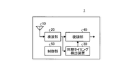
- FIG. 1 is a block diagram showing an example of the configuration of the wireless communication device 1.
- the wireless communication device 1 includes an antenna 10, a detection unit 20, a synchronization timing detection device 30, a demodulation unit 40, and a control unit 50.
- the wireless communication device 1 is a digital wireless communication device.
- the antenna 10 receives an RF signal transmitted from a wireless communication device different from the wireless communication device 1.
- the antenna 10 receives, for example, an RF signal modulated by a quaternary FSK (Frequency Shift Keying).
- the antenna 10 outputs the received RF signal to the detection unit 20.
- the detection unit 20 detects the RF signal.
- the detection unit 20 includes, for example, an RF (Radio Frequency) circuit unit (not shown), an orthogonal detection unit, an A / D (Analog to Digital) conversion unit, and a reception data conversion unit.
- the RF circuit unit executes a process of changing the frequency of the RF signal received from the antenna 10.
- the RF circuit unit for example, changes the signal to an intermediate frequency and outputs it to the orthogonal detection unit.
- the orthogonal detection unit executes orthogonal detection on the signal received from the RF circuit unit, and outputs the detected orthogonal signal to the A / D conversion unit.
- the A / D conversion unit executes analog-to-digital conversion to convert the two orthogonal signals I and Q that have been orthogonally detected by the orthogonal detection unit into digital signals, and outputs the signals to the reception data conversion unit.
- the received data conversion unit converts an orthogonal signal into a received signal. If the signal is modulated by the above-mentioned four-value FSK, FM detection is executed by arc tangent detection and converted into a received signal.
- the received signal output from the received data conversion unit is output to the synchronization timing detection device 30 and the demodulation unit 40.
- the A / D converter oversamples, for example, a dozen times (for example, 16 times) the symbol rate. Therefore, the received signal output from the received data conversion unit is a signal oversampled with respect to the symbol rate. Therefore, the detection unit 20 receives the RF signal and outputs the received signal oversampled with respect to the symbol rate.
- the synchronization timing detection device 30 detects the timing of symbol synchronization.
- the synchronization timing detection device 30 outputs timing information (symbol synchronization signal) regarding the timing for starting symbol synchronization.
- the synchronization timing detection device 30 also detects the timing of frame synchronization.
- the synchronization timing detection device 30 outputs timing information (frame synchronization signal) regarding the timing for starting frame synchronization.
- the configuration and processing of the synchronization timing detection device 30 will be described later.
- the demodulation unit 40 executes demodulation processing of the received signal based on the timing information detected by the synchronization timing detection device 30.
- the control unit 50 controls each unit constituting the wireless communication device 1. That is, the control unit 50 controls each unit of the detection unit 20, the synchronization timing detection device 30, and the demodulation unit 40.
- the control unit 50 is composed of, for example, a CPU (Central Processing Unit), a RAM (Random Access Memory), a ROM (Read Only Memory), and the like.
- the ROM stores a program for the CPU to control each part.
- the CPU controls each part of the wireless communication device 1 by reading a program stored in the ROM, allocating a data area in the RAM, and executing the program.
- the control unit 50 realizes each function of the wireless communication device 1 of the present embodiment by executing a program recorded on a computer-readable non-temporary recording medium.
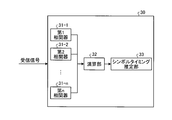
- FIG. 2 is a block diagram showing an example of a basic configuration of the synchronous timing detection device according to the embodiment of the present disclosure.
- the synchronous timing detection device 30 includes a first correlator 31-1, a second correlator 31-2, ..., an nth (n is a natural number of 3 or more) correlator 31-n, and a calculation unit 32. , A symbol timing estimation unit 33 is provided.
- the first correlator 31-1 to the nth correlator 31-n each receive an oversampled received signal at m times.
- the first correlator 31-1 to the nth correlator 31-n derive a correlation value R between different predetermined sample timing signals and a known synchronization pattern.
- the predetermined sample timing is deviated by m / n (n is 3 ⁇ n ⁇ m, n is a natural number and a divisor of m).
- the sampling deviation of the correlation value Rn is 4 samples when m is 16 and n is 4.
- Each correlator 31-n derives a correlation value from the first, fifth, ninth, and thirteenth samples of 16 samples (first to 16th samples) in one symbol period.
- the first correlator 31-1 derives the correlation value R1 with the period from the first sample to the next first sample as one symbol period.
- the second correlator 31-2 derives the correlation value R2 with the period from the fifth sample to the next fifth sample as one symbol period.
- the third correlator 31-3 derives the correlation value R3 with the period from the ninth sample to the next ninth sample as one symbol period.
- the fourth correlator 31-4 derives the correlation value R4 with the period from the 13th sample to the next 13th sample as one symbol period.
- Each of the four correlators 31-n derives a correlation value Rn for each received signal whose timing is off by four samples.
- Each correlator calculates a correlation value based on the following equation (1).
- S [k] is the synchronization word data
- B [k] is the buffered received data
- l (lowercase letter L) is the data length of the synchronization word.
- FIG. 3 shows a state in which the respective correlation values Rn output from the n correlators of the first correlator 31-1 to the nth correlator 31-n are arranged for each sample timing P1 to Pm.
- the magnitude of the correlation value is indicated by an arrow pointing upward in the figure at the position of P1.
- the second correlator 31-2 to the fourth correlator.
- the calculation unit 32 repeats the calculation of the correlation value Rn until any of the correlation values Rn exceeds a predetermined threshold value.
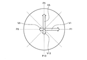
- the calculation unit 32 applies each of the correlation values Rn shown in FIG. 3 to the polar coordinates shown in FIG.
- n correlation value vectors V1 fitted with the absolute value of the correlation value as the magnitude and the angle as 2 ⁇ (n / m) [rad] on polar coordinates.
- V5, V9, V13 The calculation unit 32 calculates the vector composition of the correlation value vectors V1, V5, V9, and V13.
- the calculation unit 32 calculates the angle of the synthesized correlation value vector on the polar coordinates.
- the angle of P1 is set to 0 [rad].
- the angle of the synthesized correlation value vector is calculated by calculating the x component and the y component of each of the correlation value vectors, calculating the difference between the x component and the y component, and reversing from the calculated x component and the y component.
- the tangent may be calculated.
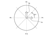
- the calculation unit 32 calculates the difference between the x components and the difference between the y components of the correlation value vectors V1, V5, V9, and V12 arranged every 90 degrees, where the number n of the correlators is 4. As shown in FIG.
- the calculation unit 32 calculates the x component and the y component of the correlation value vector by the following equation (2) for the x component and the following equation (3) for the y component, and further, x The difference between the components (Vx) and the difference between the y components (Vy) are calculated.
- the calculation unit 32 calculates the inverse tangent from Vx and Vy according to the following equation (4) in order to obtain the angle of the synthesized correlation value vector.
- the synchronous timing detection device 30 does not calculate the correlation value starting from all the sample timings in one symbol period (P1 to P16), but at predetermined intervals.
- the correlation value is calculated starting from the thinned sample timing. Therefore, it is necessary to estimate the magnitude of the correlation value and the sample timing when the correlation value is maximized.
- the calculation unit 32 applies each of the correlation values of the thinned sample timings on polar coordinates to obtain a correlation value vector. Since 16 samples can be represented in one round of angles on polar coordinates, the angle formed by each correlation value vector is the sample timing that is the starting point for calculating the correlation value. Therefore, the result of vector synthesis of each correlation value vector by the calculation unit 32 shows the correlation value vector when the correlation value becomes maximum. Therefore, it can be estimated that the angle (predicted angle ⁇ 1) formed by the correlation value vector after the vector synthesis calculated by the calculation unit 32 is the sample timing at which the correlation value becomes maximum.
- the symbol timing estimation unit 33 estimates the symbol timing at which the symbols are synchronized based on the prediction angle ⁇ 1. As shown in FIG. 4, one round in polar coordinates is one symbol period. The symbol timing estimation unit 33 estimates that the correlation value becomes maximum at the prediction angle ⁇ 1. Further, as shown in FIG. 4, the symbol timing estimation unit 33 estimates the sample timing corresponding to the angle at which the correlation value is maximized because one round in polar coordinates is one symbol period. Further, the symbol timing estimation unit 33 estimates the timing at which the symbols are synchronized from the sample timing at which the correlation value becomes maximum. Therefore, when the received signal is sampled from the sample timing corresponding to the prediction angle ⁇ 1, it can be said that the correlation value with the synchronization word becomes maximum.
- the timing of the synchronization word can be estimated. Further, since the position of the symbol (symbol timing) in the waveform of the synchronization word is known, the timing of the synchronization word itself can be estimated by estimating the sample timing that maximizes the correlation value with the synchronization word. Can estimate when the symbols are synchronized.
- FIG. 7 is a functional block diagram showing in detail the synchronization timing device according to the present embodiment.
- the sampling rate on the receiving side is oversampled m times on the transmitting side, for example, 16 times.
- the synchronization timing detection device 30A includes 16 buffers.
- the sampling rate on the receiving side is oversampled to 16 times that on the transmitting side, but this is an example and does not limit the present disclosure.
- the sampling rate on the receiving side may be set to a dozen times higher than that on the transmitting side.
- the synchronization timing detection device 30A includes the first buffer 110-1 to the 16th buffer 110-16, the first correlator 31-1 to the fourth correlator 31-4, the calculation unit 32, and a symbol. It includes a timing estimation unit 33, a selector 34, a synchronization determination correlator 35, a frame timing determination unit 36, and a symbol timing determination unit 37.
- Each of the 16 buffers is shifted by one sample to store the received signal. Similar to the basic configuration described in FIG. 2, m / n (n is 3 ⁇ n ⁇ m, n is a natural number and a divisor of m) is output from a buffer whose sample timing is deviated by n correlators. Correlation determination with the synchronization word is performed for each of the received signals. Since the number of correlators is 4, n is 4, and the correlation value with the synchronization word is calculated for the output from the buffer shifted by 4 samples.
- the output of the first buffer 110-1 is the output of the first correlator 31-1
- the output of the fifth buffer 110-5 is the output of the second correlator 31-2
- the output of the ninth buffer 110-9 is the output of the third correlator 31.
- -3 calculates the output of the 13th buffer 110-13
- the fourth correlator 31-4 calculates the correlation value.
- the calculation unit 32 calculates the prediction angle ⁇ 1, but the description is omitted because it is the same as the basic configuration shown in FIG.
- the symbol timing estimation unit 33 estimates which of Pm (P1 to P16) on the polar coordinates shown in FIG. 4 is obtained from the prediction angle ⁇ 1 calculated by the calculation unit 32. Since Pm has one symbol period as one round, the angle indicated by the predicted angle ⁇ 1 means the sample timing. Strictly speaking, since the predicted angle ⁇ 1 that maximizes the correlation value does not apply to any of the angles obtained by dividing one circumference into 16, the symbol timing estimation unit 33 estimates Pm that is the closest angle to the predicted angle ⁇ 1. You may.
- the symbol timing estimation unit 33 instructs the selector 34 to select a received signal stored in the buffer of the corresponding sample timing from the estimated value Pm of the symbol timing estimated by the symbol timing estimation unit 33.
- the calculation unit 32 calculates the predicted angle ⁇ 1 as 45 degrees.
- the symbol timing estimation unit 33 estimates that the sample timing at which the correlation value is maximum is P3, based on the calculation result of the calculation unit 32, which is 45 degrees. Based on the estimation by the symbol timing estimation unit 33 as P3, the selector 34 selects the received signal stored in the third buffer 110-3 and outputs it to the synchronization determination correlator 35.
- the synchronization determination correlator 35 calculates the correlation value with the synchronization word for the received signal of the buffer sampled at the timing P3 estimated to maximize the correlation value estimated by the symbol timing estimation unit 33, and calculates the frame. Output to the timing determination unit 36 and the symbol timing determination unit 37.
- the frame timing determination unit 36 determines the frame timing if the correlation value calculated by the synchronization determination correlator 35 is equal to or greater than a predetermined threshold value.
- the frame timing determination unit 36 generates a frame synchronization signal based on the determined frame timing and outputs it to the demodulation unit 40.
- the symbol timing determination unit 37 determines the symbol timing in the received signal if the correlation value calculated by the synchronization determination correlator 35 is equal to or greater than a predetermined threshold value.
- the symbol timing determination unit 37 generates a symbol synchronization signal based on the determined symbol timing and outputs it to the demodulation unit 40. Since the frame timing determination unit 36 and the symbol timing determination unit 37 generate synchronization signals as well as determinations, these two are referred to as synchronization signal generation units 38.
- the demodulation unit 40 executes the demodulation process of the received signal based on the timing information detected by the synchronization timing detection device 30, that is, the frame synchronization signal and the symbol synchronization signal.
- the symbol timing is estimated by calculating the correlation value of 5 buffers out of 16 buffers and the arctan when predicting the maximum correlation value.
- the processing amount of arctan's calculation is equivalent to that of calculating the correlation value of one buffer when replaced with, for example, the Chebyshev approximation formula. That is, in the present embodiment, when the synchronization timing detection device includes 16 buffers, the synchronization timing can be detected by the same processing as the calculation amount for calculating the correlation value of the 6 buffers.
- the synchronization timing detection device when the synchronization timing detection device has 16 buffers, it is necessary to calculate the correlation values of all 16 buffers when detecting the synchronization timing. there were. That is, in the present embodiment, the synchronization timing can be detected with less than half the amount of calculation as compared with the conventional method.
- the calculation unit 32 detects the correlation values of the four buffers of the first buffer 110-1, the fifth buffer 110-5, the ninth buffer 110-9, and the thirteenth buffer 110-13. Then, the symbol timing was estimated. However, in the present disclosure, the calculation unit 32 can calculate the angle and estimate the symbol timing by synthesizing the vectors if the number is three or more.
- FIG. 9 is a flowchart showing an example of a flow of processing for detecting the synchronization timing according to the present embodiment.
- a predetermined number of correlators calculate the correlation value between the received signal stored in the corresponding buffer (predetermined buffer) and the synchronization word (step S101).
- step S101 If any of the correlation values calculated in step S101 is equal to or greater than a predetermined threshold value (Yes in step S102), the calculation unit 32 has the maximum correlation value in polar coordinates based on the correlation value received from the correlator.
- the predicted angle ⁇ 1 corresponding to is calculated (step S103).
- step S101 If any of the correlation values calculated in step S101 is less than a predetermined threshold value (No in step S102), the process returns to step S101, and the calculation unit 32 calculates the correlation value of the predetermined buffer. If the received signal is not a synchronization word, the correlation value does not increase in any of the correlators, so this is a process for not performing the processes after step S103.
- the symbol timing estimation unit 33 selects a buffer of the corresponding sample timing from the sample timing corresponding to the prediction angle ⁇ 1 calculated by the calculation unit 32, and the synchronization determination correlator 35 receives the received signal stored in the corresponding buffer.
- the correlation value between and the synchronization word is calculated (step S104).
- step S104 If the correlation value calculated in step S104 is less than a predetermined threshold value (No in step S105), the process returns to step S101.
- step S104 If the correlation value calculated in step S104 is equal to or greater than a predetermined threshold value (Yes in step S105), the frame timing determination unit 36 determines the frame timing and generates a frame synchronization signal, and the symbol timing determination unit 37 symbolizes. The timing is determined and a symbol synchronization signal is generated (step S106). Then, the process of FIG. 9 ends.
- the threshold value of the correlation value for estimating the sample timing in step S102 may be lower than the threshold value of the correlation value for the synchronization determination correlator in step 105 to perform the synchronization determination. This is because, at the estimation stage, the phases of the received signal of the buffer stored starting from the thinned sample timing and the synchronization word do not always match, and the correlation value does not easily increase. However, since the received signal input to the synchronization determination correlator is the received signal stored in the buffer starting from the sample timing estimated to have the maximum correlation value, it can be expected that the correlation value will be high. Therefore, the threshold value of the correlation value may be increased.
- the amount of calculation for detecting the synchronization timing is suppressed to less than half as compared with the conventional case by thinning out the buffer for calculating the correlation value. be able to.
- the correlation value of the buffer predicted to be the synchronization timing can be calculated, and the correlation value can be compared with the correlation value of the buffer calculated to predict the synchronization timing.
- the present embodiment can improve the detection accuracy of the synchronization timing.
- the embodiments of the present disclosure have been described above, the embodiments are not limited by the contents of these embodiments. Further, the above-mentioned components include those that can be easily assumed by those skilled in the art, those that are substantially the same, that is, those having a so-called equal range. Furthermore, the components described above can be combined as appropriate. Further, various omissions, replacements or changes of components can be made without departing from the gist of the above-described embodiment.
- the synchronization timing detection device, wireless communication device, and program according to the present embodiment can be used, for example, in a wireless communication device that receives a digital signal.
- Wireless communication device 10 Antenna 20 Detection unit 30, 30A Synchronous timing detector 31-1 1st correlator 31-2 2nd correlator 31-3 3rd correlator 31-4 4th correlator 32 Calculation unit 33 Symbol timing Estimator 34 Selector 35 Synchronous judgment correlator 36 Frame timing judgment unit 37 Symbol timing judgment unit 38 Synchronous signal generation unit 40 Demodulation unit 110-1 1st buffer 110-5 5th buffer 110-9 9th buffer 110-13th 13 buffers
Landscapes
- Engineering & Computer Science (AREA)
- Computer Networks & Wireless Communication (AREA)
- Signal Processing (AREA)
- Synchronisation In Digital Transmission Systems (AREA)
Abstract
同期タイミング検出装置は、1シンボル期間をm(mは自然数)倍でオーバーサンプリングされた受信信号と、既知の同期用パターンとの相関値Rをm/nサンプルずつずらして算出して出力するn個(nは3≦n≦m、nは自然数かつmの約数)の相関器(31-1,31-2,31-3,31-4)と、n個の相関器(31-1,31-2,31-3,31-4)から出力される相関値Rnの各々を極座標上に角度2π(n/m)としてあてはめたn個の相関値ベクトルとし、n個の相関値ベクトルを合成し、合成したベクトルの角度を算出する演算部(32)と、演算部が算出したベクトルの角度に基づいて、受信信号のシンボルタイミングを推定するシンボルタイミング推定部(33)と、を備える。
Description
本開示は、同期タイミング検出装置、無線通信装置、およびプログラムに関する。
デジタル無線通信では、送信側は、所定の信号配列パターンを有する同期ワードを配置して、フレーム単位でデータを送信する。受信側は、同期ワードを検出することで、シンボル同期を図り受信したデータを復調する。
例えば、特許文献1には、受信電力が大きく変動する場合であっても受信信号のシンボルと同期を図ることのできる技術が開示されている。
しかしながら、従来では、シンボル同期を検出する際に、シンボルレートの十数倍(例えば、16倍)のサンプリングレートで1つのサンプルごとに同期ワードとの相関値を算出している。その結果、情報処理量が多くなり、シンボル同期を検出するための処理負荷が大きくなってしまう。
本開示は、シンボル同期を検出するための処理負荷を低減することのできる同期タイミング検出装置、無線通信装置、およびプログラムを提案する。
本開示の同期タイミング検出装置は、1シンボル期間をm(mは自然数)倍でオーバーサンプリングされた受信信号と、既知の同期用パターンとの相関値Rをm/nサンプルずつずらして算出して出力するn個(nは3≦n≦m、nは自然数かつmの約数)の相関器と、前記n個の相関器から出力される相関値Rnの各々を極座標上に角度2π(n/m)としてあてはめたn個の相関値ベクトルとし、n個の相関値ベクトルを合成し、合成したベクトルの角度を算出する演算部と、前記演算部が算出したベクトルの角度に基づいて、前記受信信号のシンボルタイミングを推定するシンボルタイミング推定部と、を備える。
本開示のデジタル無線通信装置は、RF信号を検波し、受信信号に変換する検波部と、前記受信信号を復調する復調部と、前記復調部が前記受信信号を復調するための同期信号を生成する同期タイミング検出装置と、を備え、前記同期タイミング検出装置は、1シンボル期間をm(mは自然数)倍でオーバーサンプリングされた前記受信信号と、既知の同期用パターンとの相関値Rをm/nサンプルずつずらして算出して出力するn個(nは3≦n≦m、nは自然数かつmの約数)の相関器と、前記n個の相関器から出力される相関値Rnの各々を極座標上に角度2π(n/m)としてあてはめたn個の相関値ベクトルとし、n個の相関値ベクトルを合成し、合成したベクトルの角度を算出する演算部と、前記演算部が算出したベクトルの角度に基づいて、前記受信信号のシンボルタイミングを推定するシンボルタイミング推定部と、推定したシンボルタイミングに基づいて、前記同期信号を生成する同期信号生成部と、を備える。
本開示のプログラムは、1シンボル期間をm(mは自然数)倍でオーバーサンプリングした受信信号と、既知の同期用パターンとの相関値をm/nサンプルおきにn個(nは3≦n≦m、nは自然数かつmの約数)の相関値Rnを算出して出力する相関値算出ステップと、前記n個の相関器から出力される相関値Rnの各々を極座標上に角度2π(n/m)としてあてはめたn個の相関値ベクトルとし、n個の相関値ベクトルを合成し、合成したベクトルの角度を算出する角度算出ステップと、前記角度に基づいて、シンボルが同期するシンボルタイミングを推定する推定ステップと、を同期タイミング検出装置として動作するコンピュータに実行させる。
本開示によれば、シンボル同期を検出するための処理負荷を低減することができる。
以下、添付図面を参照して、本開示に係る実施形態を詳細に説明する。なお、この実施形態により本開示が限定されるものではなく、また、実施形態が複数ある場合には、各実施形態を組み合わせて構成するものも含む。
[実施形態]
図1を用いて、本開示の実施形態に係る無線通信装置1の構成について説明する。図1は、無線通信装置1の構成の一例を示すブロック図である。
図1を用いて、本開示の実施形態に係る無線通信装置1の構成について説明する。図1は、無線通信装置1の構成の一例を示すブロック図である。
無線通信装置1は、アンテナ10と、検波部20と、同期タイミング検出装置30と、復調部40と、制御部50とを備える。本実施形態において、無線通信装置1は、デジタル無線通信装置である。
アンテナ10は、無線通信装置1とは異なる無線通信装置から送信されたRF信号を受信する。アンテナ10は、例えば4値FSK(Frequency Shift Keying)で変調されたRF信号を受信する。アンテナ10は、受信したRF信号を検波部20に出力する。
検波部20は、RF信号を検波する。具体的には、検波部20は、例えば図示しないRF(Radio Frequency)回路部と、直交検波部と、A/D(Analog to Digital)変換部と、受信データ変換部とを有する。RF回路部は、アンテナ10から受けたRF信号に対して、周波数を変更する処理などを実行する。RF回路部は、例えば信号を中間周波数に変更し、直交検波部に出力する。直交検波部は、RF回路部から受けた信号に対して、直交検波を実行し、検波した直交信号をA/D変換部に出力する。A/D変換部は、直交検波部により直交検波されたI,Q2つの直交信号を、アナログ‐デジタル変換を実行して、デジタル信号に変換し、受信データ変換部に出力する。受信データ変換部は、直交信号を受信信号に変換する。前記した4値FSKで変調された信号であればアークタンジェント検波によりFM検波を実行し、受信信号に変換する。受信データ変換部から出力された受信信号は、同期タイミング検出装置30と、復調部40とに出力される。
A/D変換部は、例えばシンボルレートに対して十数倍(例えば、16倍)にオーバーサンプリングする。よって受信データ変換部から出力される受信信号は、シンボルレートに対してオーバーサンプリングされた信号となる。よって、検波部20は、RF信号を受信し、シンボルレートに対してオーバーサンプリングされた受信信号を出力する。
同期タイミング検出装置30は、シンボル同期のタイミングを検出する。同期タイミング検出装置30は、シンボル同期を開始するタイミングに関するタイミング情報(シンボル同期信号)を出力する。また、同期タイミング検出装置30は、フレーム同期のタイミングも検出する。同期タイミング検出装置30は、フレーム同期を開始するタイミングに関するタイミング情報(フレーム同期信号)を出力する。同期タイミング検出装置30の構成や処理については後述する。
復調部40は、同期タイミング検出装置30が検出したタイミング情報に基づいて、受信信号の復調処理を実行する。
制御部50は、無線通信装置1を構成する各部を制御する。すなわち、制御部50は、検波部20と、同期タイミング検出装置30と、復調部40との各部を制御する。制御部50は、例えばCPU(Central Processing Unit)、RAM(Random Acccess Memory)、ROM(Read Only Memory)などで構成されている。この場合、ROMには、CPUが各部を制御するためのプログラムが格納されている。CPUは、ROMに格納されたプログラムを読み出し、RAMにデータ領域を確保して実行することで、無線通信装置1の各部を制御する。言い換えると、制御部50は、コンピュータ読み取り可能な非一時的な記録媒体に記録されたプログラムを実行することにより、本実施形態の無線通信装置1の各機能を実現する。
[同期タイミング検出装置]
図2を用いて、本開示の実施形態に係る同期タイミング検出装置について説明する。図2は、本開示の実施形態に係る同期タイミング検出装置の基本構成の一例を示すブロック図である。
図2を用いて、本開示の実施形態に係る同期タイミング検出装置について説明する。図2は、本開示の実施形態に係る同期タイミング検出装置の基本構成の一例を示すブロック図である。
同期タイミング検出装置30は、第1相関器31-1と、第2相関器31-2と、・・・、第n(nは3以上の自然数)相関器31-nと、演算部32と、シンボルタイミング推定部33とを備える。
第1相関器31-1から第n相関器31-nは、それぞれ、m倍でオーバーサンプリングされた受信信号を受ける。第1相関器31-1から第n相関器31-nは、それぞれ異なる所定のサンプルタイミングの信号と、既知の同期用パターンとの相関値Rを導出する。所定のサンプルタイミングは、m/n(nは3≦n≦m、nは自然数かつmの約数)サンプルずつずれている。例えば、相関値Rnのサンプリングのずれは、mを16とし、nを4とすると4サンプルとなる。1シンボル期間の16サンプル(第1~第16サンプル)の第1、第5、第9、第13サンプルを起点として、それぞれの相関器31-nが相関値を導出する。つまり、第1相関器31-1は、第1サンプルから次の第1サンプルまでを1シンボル期間として相関値R1を導出する。第2相関器31-2は、第5サンプルから次の第5サンプルまでを1シンボル期間として相関値R2を導出する。第3相関器31-3は、第9サンプルから次の第9サンプルまでを1シンボル期間として相関値R3を導出する。第4相関器31-4は、第13サンプルから次の第13サンプルまでを1シンボル期間として相関値R4を導出する。4つの相関器31-nは、それぞれ4サンプルずつタイミングがずれた受信信号に対して相関値Rnをそれぞれ導出する。なお、各相関器は、下記の式(1)に基づいて相関値を算出する。

式(1)において、S[k]は同期ワードのデータ、B[k]はバッファされた受信データである。また、l(Lの小文字)は同期ワードのデータ長である。
図3は、第1相関器31-1から第n相関器31-nのn個の相関器から出力されるそれぞれの相関値RnをサンプルタイミングP1~Pm毎に並べた状態を示している。例えば、第1相関器31-1の出力は、P1の位置で相関値の大きさを図の上方向の矢印で示している。第2相関器31-2~第4相関器も同様である。
演算部32は、相関値Rnのいずれが所定のしきい値を超えるまで相関値Rnの算出を繰り返す。演算部32は、相関値Rnのいずれかが所定のしきい値を超えた場合、図3で示した相関値Rnの各々を、図4で示す極座標に当てはめる。その結果、相関値Rnの各々は、図5に示すように極座標上に、相関値の絶対値を大きさとし、角度を2π(n/m)[rad]としてあてはめたn個の相関値ベクトルV1、V5、V9、V13として表される。演算部32は、相関値ベクトルV1、V5、V9、V13のベクトル合成の演算を行う。演算部32は、合成した相関値ベクトルの極座標上における角度を算出する。なお説明を容易にするため、P1の角度を0[rad]としている。
合成した相関値ベクトルの角度の算出は、相関値ベクトル各々のx成分とy成分とを算出し、x成分とy成分とそれぞれの差分を算出し、算出後のx成分とy成分とから逆正接を算出してもよい。例えば、演算部32は、相関器の数nを4として90度ごとに配置された相関値ベクトルV1、V5、V9、V12のそれぞれのx成分の差分と、y成分の差分を算出する。図6に示すように、演算部32は、x成分は下記の式(2)、y成分は下記の式(3)により相関値ベクトルのそれぞれのx成分とy成分とを算出し、さらにx成分の差分(Vx)と、y成分の差分(Vy)とを算出する。

演算部32は、合成した相関値ベクトルの角度を求めるため、下記の式(4)に従って、VxとVyとから逆正接を算出する。

演算部32が、ベクトル合成を行い、角度を求める理由は、相関値が最大となるサンプルタイミングを推定するためである。図3に示すように、本開示の実施形態に係る同期タイミング検出装置30は、1シンボル期間(P1~P16)の全てのサンプルタイミングを起点として相関値を算出するのではなく、所定の間隔で間引きしたサンプルタイミングを起点として相関値を算出している。そのため、相関値が最大になる場合の相関値の大きさとサンプルタイミングとは、推定する必要がある。
演算部32は、間引きしたサンプルタイミングの相関値の各々を極座標上にあてはめ、相関値ベクトルとする。極座標上の角度は1周で16サンプル表せるので、それぞれの相関値ベクトルのなす角度は、相関値の算出の起点となっているサンプルタイミングとなる。そのため、それぞれの相関値ベクトルを、演算部32がベクトル合成した結果は、相関値が最大となった場合の相関値ベクトルを示すことになる。そのため、演算部32により算出したベクトル合成後の相関値ベクトルのなす角度(予測角度θ1)は、相関値が最大となるサンプルタイミングとなる、と推定できる。
シンボルタイミング推定部33は、予測角度θ1に基づいて、シンボルが同期するシンボルタイミングを推定する。図4に示すように極座標における1周は1シンボル期間である。シンボルタイミング推定部33は、予測角度θ1において、相関値が最大になると推定する。さらに、シンボルタイミング推定部33は、図4に示すように極座標における1周は1シンボル期間であるため、相関値が最大となる角度に該当するサンプルタイミングを推定する。また、シンボルタイミング推定部33は、相関値が最大となるサンプルタイミングからシンボルが同期するタイミングを推定する。よって、予測角度θ1に該当するサンプルタイミングから受信信号をサンプリングした場合に、同期ワードとの相関値は最大となるといえる。同期ワードとの相関値が最大となることから、同期ワードのタイミングを推定できたといえる。また、同期ワードの波形におけるシンボルの位置(シンボルタイミング)は、既知であることから、同期ワードとの相関値が最大となるサンプルタイミングを推定することにより、同期ワードそのもののタイミングを推定でき、さらにはシンボルが同期するタイミングを推定することができる。
[同期タイミング検出方法]
図7を用いて、本実施形態に係る同期タイミング検出装置を備えた無線通信装置における同期タイミング検出方法を説明する。図7は、本実施形態に係る同期タイミング装置を詳細に示した機能ブロック図である。
図7を用いて、本実施形態に係る同期タイミング検出装置を備えた無線通信装置における同期タイミング検出方法を説明する。図7は、本実施形態に係る同期タイミング装置を詳細に示した機能ブロック図である。
本実施形態に係る同期タイミング検出装置30Aでは、受信側のサンプリングレートを送信側のm倍、例えば16倍にオーバーサンプリングする。この場合、同期タイミング検出装置30Aは、バッファを16個備えている。なお、以下の説明では、受信側のサンプリングレートを送信側の16倍にオーバーサンプリングするものとして説明するが、これは例示であり、本開示を限定するものでない。例えば受信側のサンプリングレートを送信側の十数倍に設定すればよい。
本実施形態に係る同期タイミング検出装置30Aは、第1バッファ110-1~第16バッファ110-16と、第1相関器31-1~第4相関器31-4と、演算部32と、シンボルタイミング推定部33と、セレクタ34と、同期判定用相関器35と、フレームタイミング判定部36と、シンボルタイミング判定部37とを備える。
16個のバッファのそれぞれは、1サンプルずつずらして受信信号を記憶する。図2で説明した基本構成と同じく、n個の相関器によりm/n(nは3≦n≦m、nは自然数かつmの約数)サンプルずつずれたサンプルタイミングとなるバッファから出力された受信信号のそれぞれに対して同期ワードとの相関判定を行う。相関器数を4としたため、nは4であり、4サンプルずつずれたバッファからの出力に対して同期ワードとの相関値を算出することになる。第1バッファ110-1の出力を第1相関器31-1が、第5バッファ110-5の出力を第2相関器31-2が、第9バッファ110-9の出力を第3相関器31-3が、第13バッファ110-13の出力を第4相関器31-4が、それぞれ相関値の算出を行う。演算部32は、予測角度θ1を算出するが、図2で示した基本構成と同じであるため説明は省略する。
シンボルタイミング推定部33は、演算部32において算出した予測角度θ1から、図4に示す極座標上のPm(P1~P16)のいずれとなるかを推定する。Pmは、1シンボル期間を1周としているため、予測角度θ1が示す角度は、サンプルタイミングを意味する。厳密には、1周を16分割した角度のいずれかに相関値が最大となる予測角度θ1が当てはまることはないため、シンボルタイミング推定部33は予測角度θ1に最も近い角度となるPmを推定してもよい。
シンボルタイミング推定部33は、シンボルタイミング推定部33が推定したシンボルタイミングの推定値Pmから、該当するサンプルタイミングのバッファに記憶された受信信号を選択するようセレクタ34に指示する。
例えば、図3、図5、図6、図8に示す状態である場合、演算部32は予測角度θ1を45度と算出することになる。シンボルタイミング推定部33は、演算部32の算出結果である45度に基づき、相関値が最大となるサンプルタイミングはP3であると推定する。シンボルタイミング推定部33がP3と推定したことに基づいて、セレクタ34は、第3バッファ110-3に記憶された受信信号を選択し、同期判定用相関器35に出力する。
同期判定用相関器35は、シンボルタイミング推定部33で推定した相関値が最大となると推定されたタイミングP3でサンプリングされたバッファの受信信号に対して、同期ワードとの相関値を算出し、フレームタイミング判定部36およびシンボルタイミング判定部37に出力する。
フレームタイミング判定部36は、同期判定用相関器35が算出した相関値が所定のしきい値以上であれば、フレームタイミングを判定する。フレームタイミング判定部36は、判定したフレームタイミングに基づいてフレーム同期信号を生成し、復調部40に出力する。
シンボルタイミング判定部37は、同期判定用相関器35が算出した相関値が所定のしきい値以上であれば、受信信号におけるシンボルタイミングを判定する。シンボルタイミング判定部37は、判定したシンボルタイミングに基づいてシンボル同期信号を生成し、復調部40に出力する。フレームタイミング判定部36およびシンボルタイミング判定部37はそれぞれ判定だけでなくそれぞれ同期信号を生成することから、これら2つを同期信号生成部38とする。
前記したように、復調部40は、同期タイミング検出装置30が検出したタイミング情報、つまりフレーム同期信号およびシンボル同期信号に基づいて、受信信号の復調処理を実行する。
本実施形態は、16個のバッファのうち、5個のバッファの相関値と、最大の相関値予測する際のarctanの計算を行うことでシンボルタイミングを推定する。arctanの計算の処理量は、例えばチェビシェフ近似式に置き換えた場合、1つのバッファの相関値を計算する場合と同等となる。すなわち、本実施形態は、同期タイミング検出装置が16個のバッファを備えている場合において、6個のバッファの相関値を算出する演算量と同等の処理で、同期タイミングを検出することができる。
一方、上述したように、従来の方法では、同期タイミング検出装置では16個のバッファを備えている場合に、同期タイミングを検出する場合には、16個全てのバッファの相関値を算出する必要があった。すなわち、本実施形態は、従来の方法と比較すると、半分以下の演算量で同期タイミングを検出することができる。
なお、上述では、演算部32は、第1バッファ110-1と、第5バッファ110-5と、第9バッファ110-9と、第13バッファ110-13との4つのバッファの相関値を検出して、シンボルタイミングを推定した。しかしながら、本開示では、演算部32は、3つ以上であればベクトルの合成により、角度を算出しシンボルタイミングを推定することができる。
図9を用いて、本実施形態に係る同期タイミングを検出する処理の流れについて説明する。図9は、本実施形態に係る同期タイミングを検出する処理の流れの一例を示すフローチャートである。
所定数の相関器(第1から第n相関器)は、対応するバッファ(所定のバッファ)に記憶された受信信号と同期ワードとの相関値を算出する(ステップS101)。
ステップS101で算出した相関値のいずれかが、所定のしきい値以上であれば(ステップS102のYes)、演算部32は、相関器から受けた相関値に基づいて、極座標において最大の相関値に対応する予測角度θ1を算出する(ステップS103)。
ステップS101で算出した相関値のいずれかが、所定のしきい値未満であれば(ステップS102のNo)、ステップS101に戻り、演算部32は、所定のバッファの相関値の算出を行う。受信信号が同期ワードでは無い場合には、いずれの相関器も相関値は上がらないことから、ステップS103以降の処理を行なわないための処理である。
シンボルタイミング推定部33は、演算部32が算出した予測角度θ1に対応するサンプルタイミングから、該当するサンプルタイミングのバッファを選択し、同期判定用相関器35は、該当するバッファに記憶された受信信号と同期ワードとの相関値を算出する(ステップS104)。
ステップS104で算出した相関値が、所定のしきい値未満であれば(ステップS105のNo)、ステップS101に戻る。
ステップS104で算出した相関値が、所定のしきい値以上であれば(ステップS105のYes)、フレームタイミング判定部36がフレームタイミングを判定しフレーム同期信号を生成し、シンボルタイミング判定部37がシンボルタイミングを判定しシンボル同期信号を生成する(ステップS106)。そして、図9の処理は終了する。
ステップS102におけるサンプルタイミングを推定するための相関値のしきい値は、ステップ105における同期判定用相関器が同期判定を行うための相関値のしきい値に比べて低くてもよい。これは、推定の段階では、間引きしたサンプルタイミングを起点として記憶したバッファの受信信号と同期ワードとの位相がかならずしも一致せず、相関値は上がりにくいためである。しかし、同期判定用相関器に入力される受信信号は、相関値が最大となると推測されたサンプルタイミングを起点としたバッファに記憶された受信信号であるため、相関値は高くなることが予想できることから、相関値のしきい値を高くてもよい。
上述のとおり、本実施形態は、受信側でサンプリングレートを十数倍した場合において、相関値を演算するバッファを間引くことによって、同期タイミングを検出する演算量を従来と比べて半分以下に抑制することができる。
また、本実施形態は、同期タイミングであると予測されたバッファの相関値を算出し、その相関値と、同期タイミングを予測するために算出したバッファの相関値とを比較することができる。その結果、本実施形態は、同期タイミングの検出精度を向上させることができる。
以上、本開示の実施形態を説明したが、これら実施形態の内容により実施形態が限定されるものではない。また、前述した構成要素には、当業者が容易に想定できるもの、実質的に同一のもの、いわゆる均等の範囲のものが含まれる。さらに、前述した構成要素は適宜組み合わせることが可能である。さらに、前述した実施形態の要旨を逸脱しない範囲で構成要素の種々の省略、置換又は変更を行うことができる。
本実施形態に係る同期タイミング検出装置、無線通信装置、およびプログラムは、例えば、デジタル信号を受信する無線通信装置に利用することができる。
1 無線通信装置
10 アンテナ
20 検波部
30,30A 同期タイミング検出装置
31-1 第1相関器
31-2 第2相関器
31-3 第3相関器
31-4 第4相関器
32 演算部
33 シンボルタイミング推定部
34 セレクタ
35 同期判定用相関器
36 フレームタイミング判定部
37 シンボルタイミング判定部
38 同期信号生成部
40 復調部
110-1 第1バッファ
110-5 第5バッファ
110-9 第9バッファ
110-13 第13バッファ
10 アンテナ
20 検波部
30,30A 同期タイミング検出装置
31-1 第1相関器
31-2 第2相関器
31-3 第3相関器
31-4 第4相関器
32 演算部
33 シンボルタイミング推定部
34 セレクタ
35 同期判定用相関器
36 フレームタイミング判定部
37 シンボルタイミング判定部
38 同期信号生成部
40 復調部
110-1 第1バッファ
110-5 第5バッファ
110-9 第9バッファ
110-13 第13バッファ
Claims (5)
- 1シンボル期間をm(mは自然数)倍でオーバーサンプリングされた受信信号と、既知の同期用パターンとの相関値Rをm/nサンプルずつずらして算出して出力するn個(nは3≦n≦m、nは自然数かつmの約数)の相関器と、
前記n個の相関器から出力される相関値Rnの各々を極座標上に角度2π(n/m)としてあてはめたn個の相関値ベクトルとし、n個の相関値ベクトルを合成し、合成したベクトルの角度を算出する演算部と、
前記演算部が算出したベクトルの角度に基づいて、前記受信信号のシンボルタイミングを推定するシンボルタイミング推定部と、
を備える、同期タイミング検出装置。 - RF信号を検波し、受信信号に変換する検波部と、
前記受信信号を復調する復調部と、
前記復調部が前記受信信号を復調するための同期信号を生成する同期タイミング検出装置と、
を備え、
前記同期タイミング検出装置は、
1シンボル期間をm(mは自然数)倍でオーバーサンプリングされた前記受信信号と、既知の同期用パターンとの相関値Rをm/nサンプルずつずらして算出して出力するn個(nは3≦n≦m、nは自然数かつmの約数)の相関器と、
前記n個の相関器から出力される相関値Rnの各々を極座標上に角度2π(n/m)としてあてはめたn個の相関値ベクトルとし、n個の相関値ベクトルを合成し、合成したベクトルの角度を算出する演算部と、
前記演算部が算出したベクトルの角度に基づいて、前記受信信号のシンボルタイミングを推定するシンボルタイミング推定部と、
推定したシンボルタイミングに基づいて、前記同期信号を生成する同期信号生成部と、
を備える、
無線通信装置。 - 前記同期タイミング検出装置は、
1シンボル期間をm(mは自然数)倍でオーバーサンプリングされた前記受信信号を、1サンプルずつずらしたタイミングを起点として記憶するm個のバッファと、
前記シンボルタイミング推定部が推定したシンボルタイミングに基づいてm個のバッファから1つのバッファを選択するセレクタと、
前記セレクタで選択したバッファに記憶された受信信号と、既知の同期用パターンとの相関値を算出する同期判定用相関器と、
前記同期判定用相関器が算出した相関値が所定のしきい値以上の場合に、前記復調部に前記同期信号としてフレーム同期信号を生成して出力するフレームタイミング判定部と、
前記同期判定用相関器が算出した相関値が所定のしきい値以上の場合に、前記復調部に前記同期信号としてシンボル同期信号を生成して出力するシンボルタイミング判定部と、
を備える請求項2に記載の無線通信装置。 - 1シンボル期間をm(mは自然数)倍でオーバーサンプリングした受信信号と、既知の同期用パターンとの相関値をm/nサンプルおきにn個(nは3≦n≦m、nは自然数かつmの約数)の相関値Rnを算出して出力する相関値算出ステップと、
前記n個の相関器から出力される相関値Rnの各々を極座標上に角度2π(n/m)としてあてはめたn個の相関値ベクトルとし、n個の相関値ベクトルを合成し、合成したベクトルの角度を算出する角度算出ステップと、
前記角度に基づいて、シンボルが同期するシンボルタイミングを推定する推定ステップと、
を同期タイミング検出装置として動作するコンピュータに実行させるための、プログラム。 - 前記相関値Rnのいずれかが所定のしきい値を超えた場合に、前記角度算出ステップを行う判定ステップをさらに含む請求項4に記載のプログラム。
Priority Applications (1)
| Application Number | Priority Date | Filing Date | Title |
|---|---|---|---|
| US17/463,585 US11658797B2 (en) | 2019-03-18 | 2021-09-01 | Synchronization timing detector, wireless communication device, and non-transitory computer-readable recording medium |
Applications Claiming Priority (2)
| Application Number | Priority Date | Filing Date | Title |
|---|---|---|---|
| JP2019-049897 | 2019-03-18 | ||
| JP2019049897A JP7070481B2 (ja) | 2019-03-18 | 2019-03-18 | 同期タイミング検出装置、無線通信装置、およびプログラム |
Related Child Applications (1)
| Application Number | Title | Priority Date | Filing Date |
|---|---|---|---|
| US17/463,585 Continuation US11658797B2 (en) | 2019-03-18 | 2021-09-01 | Synchronization timing detector, wireless communication device, and non-transitory computer-readable recording medium |
Publications (1)
| Publication Number | Publication Date |
|---|---|
| WO2020188912A1 true WO2020188912A1 (ja) | 2020-09-24 |
Family
ID=72519780
Family Applications (1)
| Application Number | Title | Priority Date | Filing Date |
|---|---|---|---|
| PCT/JP2019/048446 Ceased WO2020188912A1 (ja) | 2019-03-18 | 2019-12-11 | 同期タイミング検出装置、無線通信装置、およびプログラム |
Country Status (3)
| Country | Link |
|---|---|
| US (1) | US11658797B2 (ja) |
| JP (1) | JP7070481B2 (ja) |
| WO (1) | WO2020188912A1 (ja) |
Families Citing this family (1)
| Publication number | Priority date | Publication date | Assignee | Title |
|---|---|---|---|---|
| JP7164810B2 (ja) * | 2018-09-06 | 2022-11-02 | 日本電信電話株式会社 | 信号処理装置及び光受信器 |
Citations (2)
| Publication number | Priority date | Publication date | Assignee | Title |
|---|---|---|---|---|
| JPH11103326A (ja) * | 1997-09-26 | 1999-04-13 | Mitsubishi Electric Corp | 復調器 |
| JP2001217888A (ja) * | 2000-02-04 | 2001-08-10 | Mitsubishi Electric Corp | タイミング再生装置および復調器 |
Family Cites Families (4)
| Publication number | Priority date | Publication date | Assignee | Title |
|---|---|---|---|---|
| US5140617A (en) * | 1990-02-07 | 1992-08-18 | Mitsubishi Denki Kabushiki Kaisha | Frame phase estimation method and circuit |
| JP3125644B2 (ja) * | 1995-09-13 | 2001-01-22 | 松下電器産業株式会社 | 復調装置 |
| KR101105399B1 (ko) * | 2008-12-22 | 2012-01-17 | 한국전자통신연구원 | 직교주파수분할다중접속 시스템의 시간 동기 검출 장치 및 방법과 수신 장치 |
| JP5283182B2 (ja) | 2009-03-23 | 2013-09-04 | 株式会社ネットコムセック | シンボル同期装置及びシンボル同期方法 |
-
2019
- 2019-03-18 JP JP2019049897A patent/JP7070481B2/ja active Active
- 2019-12-11 WO PCT/JP2019/048446 patent/WO2020188912A1/ja not_active Ceased
-
2021
- 2021-09-01 US US17/463,585 patent/US11658797B2/en active Active
Patent Citations (2)
| Publication number | Priority date | Publication date | Assignee | Title |
|---|---|---|---|---|
| JPH11103326A (ja) * | 1997-09-26 | 1999-04-13 | Mitsubishi Electric Corp | 復調器 |
| JP2001217888A (ja) * | 2000-02-04 | 2001-08-10 | Mitsubishi Electric Corp | タイミング再生装置および復調器 |
Also Published As
| Publication number | Publication date |
|---|---|
| JP2020155824A (ja) | 2020-09-24 |
| US20210399871A1 (en) | 2021-12-23 |
| US11658797B2 (en) | 2023-05-23 |
| JP7070481B2 (ja) | 2022-05-18 |
Similar Documents
| Publication | Publication Date | Title |
|---|---|---|
| JP6935425B2 (ja) | ノイズ抑圧装置、ノイズ抑圧方法、及びこれらを用いた受信装置、受信方法 | |
| US9853787B2 (en) | Carrier frequency offset estimation for wireless communication | |
| US9667291B2 (en) | Unwanted component reduction system | |
| JPH05136631A (ja) | 無変調信号検出及び周波数引き込み装置 | |
| JPH08213933A (ja) | 周波数オフセット補正装置 | |
| JP2005286729A (ja) | 同期捕捉回路およびそれを利用した受信装置 | |
| JP2014196957A (ja) | センサ装置、ターゲット応答推定方法、及びセンサ装置用ターゲット応答推定プログラム | |
| JP4359638B2 (ja) | 相関演算器及び相関演算装置 | |
| US8503594B2 (en) | Phase tracking in communications systems | |
| JP7070481B2 (ja) | 同期タイミング検出装置、無線通信装置、およびプログラム | |
| US6603819B1 (en) | Radio symbol synchronization and doppler estimation techniques | |
| JP2004080555A (ja) | Cdma無線装置及びそれに用いる簡易パス推定方法 | |
| JP2000252870A (ja) | スペクトル拡散信号の符号同期捕捉回路 | |
| JP2009118175A (ja) | 受信装置 | |
| KR100759514B1 (ko) | 무선 사설망 복조기 및 복조방법 | |
| JP3576415B2 (ja) | Ofdm受信装置 | |
| JP4105659B2 (ja) | 受信装置および受信回路 | |
| JP2012191343A (ja) | 方式判定装置および方式判定方法 | |
| JP2003152674A (ja) | 周波数同期方法及びこれを用いたofdm受信装置 | |
| JP2017216499A (ja) | 信号検出装置及び信号検出方法 | |
| JP4945747B2 (ja) | 非同期符号変調信号受信装置 | |
| JP2006279254A (ja) | タイミング検出方法ならびにそれを利用したタイミング検出装置および受信装置 | |
| JP2009049727A (ja) | アンダーサンプリングにおけるサンプリング周波数探索方法及びプログラム | |
| JP2007181016A (ja) | 判定タイミング同期回路及び受信回路 | |
| JP2000261410A (ja) | 拡散変調信号受信装置 |
Legal Events
| Date | Code | Title | Description |
|---|---|---|---|
| 121 | Ep: the epo has been informed by wipo that ep was designated in this application |
Ref document number: 19919793 Country of ref document: EP Kind code of ref document: A1 |
|
| NENP | Non-entry into the national phase |
Ref country code: DE |
|
| 122 | Ep: pct application non-entry in european phase |
Ref document number: 19919793 Country of ref document: EP Kind code of ref document: A1 |