WO2020184683A1 - 鋼板およびその製造方法 - Google Patents
鋼板およびその製造方法 Download PDFInfo
- Publication number
- WO2020184683A1 WO2020184683A1 PCT/JP2020/010944 JP2020010944W WO2020184683A1 WO 2020184683 A1 WO2020184683 A1 WO 2020184683A1 JP 2020010944 W JP2020010944 W JP 2020010944W WO 2020184683 A1 WO2020184683 A1 WO 2020184683A1
- Authority
- WO
- WIPO (PCT)
- Prior art keywords
- steel sheet
- steel
- less
- content
- ferrite
- Prior art date
- Legal status (The legal status is an assumption and is not a legal conclusion. Google has not performed a legal analysis and makes no representation as to the accuracy of the status listed.)
- Ceased
Links
Classifications
-
- C—CHEMISTRY; METALLURGY
- C22—METALLURGY; FERROUS OR NON-FERROUS ALLOYS; TREATMENT OF ALLOYS OR NON-FERROUS METALS
- C22C—ALLOYS
- C22C38/00—Ferrous alloys, e.g. steel alloys
- C22C38/18—Ferrous alloys, e.g. steel alloys containing chromium
- C22C38/40—Ferrous alloys, e.g. steel alloys containing chromium with nickel
- C22C38/58—Ferrous alloys, e.g. steel alloys containing chromium with nickel with more than 1.5% by weight of manganese
-
- B—PERFORMING OPERATIONS; TRANSPORTING
- B21—MECHANICAL METAL-WORKING WITHOUT ESSENTIALLY REMOVING MATERIAL; PUNCHING METAL
- B21B—ROLLING OF METAL
- B21B1/00—Metal-rolling methods or mills for making semi-finished products of solid or profiled cross-section; Sequence of operations in milling trains; Layout of rolling-mill plant, e.g. grouping of stands; Succession of passes or of sectional pass alternations
- B21B1/22—Metal-rolling methods or mills for making semi-finished products of solid or profiled cross-section; Sequence of operations in milling trains; Layout of rolling-mill plant, e.g. grouping of stands; Succession of passes or of sectional pass alternations for rolling plates, strips, bands or sheets of indefinite length
-
- B—PERFORMING OPERATIONS; TRANSPORTING
- B22—CASTING; POWDER METALLURGY
- B22D—CASTING OF METALS; CASTING OF OTHER SUBSTANCES BY THE SAME PROCESSES OR DEVICES
- B22D11/00—Continuous casting of metals, i.e. casting in indefinite lengths
- B22D11/12—Accessories for subsequent treating or working cast stock in situ
- B22D11/128—Accessories for subsequent treating or working cast stock in situ for removing
-
- C—CHEMISTRY; METALLURGY
- C21—METALLURGY OF IRON
- C21C—PROCESSING OF PIG-IRON, e.g. REFINING, MANUFACTURE OF WROUGHT-IRON OR STEEL; TREATMENT IN MOLTEN STATE OF FERROUS ALLOYS
- C21C7/00—Treating molten ferrous alloys, e.g. steel, not covered by groups C21C1/00 - C21C5/00
- C21C7/04—Removing impurities by adding a treating agent
-
- C—CHEMISTRY; METALLURGY
- C21—METALLURGY OF IRON
- C21C—PROCESSING OF PIG-IRON, e.g. REFINING, MANUFACTURE OF WROUGHT-IRON OR STEEL; TREATMENT IN MOLTEN STATE OF FERROUS ALLOYS
- C21C7/00—Treating molten ferrous alloys, e.g. steel, not covered by groups C21C1/00 - C21C5/00
- C21C7/10—Handling in a vacuum
-
- C—CHEMISTRY; METALLURGY
- C21—METALLURGY OF IRON
- C21D—MODIFYING THE PHYSICAL STRUCTURE OF FERROUS METALS; GENERAL DEVICES FOR HEAT TREATMENT OF FERROUS OR NON-FERROUS METALS OR ALLOYS; MAKING METAL MALLEABLE, e.g. BY DECARBURISATION OR TEMPERING
- C21D8/00—Modifying the physical properties of ferrous metals or ferrous alloys by deformation combined with, or followed by, heat treatment
- C21D8/02—Modifying the physical properties of ferrous metals or ferrous alloys by deformation combined with, or followed by, heat treatment during manufacturing of plates or strips
-
- C—CHEMISTRY; METALLURGY
- C21—METALLURGY OF IRON
- C21D—MODIFYING THE PHYSICAL STRUCTURE OF FERROUS METALS; GENERAL DEVICES FOR HEAT TREATMENT OF FERROUS OR NON-FERROUS METALS OR ALLOYS; MAKING METAL MALLEABLE, e.g. BY DECARBURISATION OR TEMPERING
- C21D8/00—Modifying the physical properties of ferrous metals or ferrous alloys by deformation combined with, or followed by, heat treatment
- C21D8/02—Modifying the physical properties of ferrous metals or ferrous alloys by deformation combined with, or followed by, heat treatment during manufacturing of plates or strips
- C21D8/0221—Modifying the physical properties of ferrous metals or ferrous alloys by deformation combined with, or followed by, heat treatment during manufacturing of plates or strips characterised by the working steps
- C21D8/0226—Hot rolling
-
- C—CHEMISTRY; METALLURGY
- C21—METALLURGY OF IRON
- C21D—MODIFYING THE PHYSICAL STRUCTURE OF FERROUS METALS; GENERAL DEVICES FOR HEAT TREATMENT OF FERROUS OR NON-FERROUS METALS OR ALLOYS; MAKING METAL MALLEABLE, e.g. BY DECARBURISATION OR TEMPERING
- C21D9/00—Heat treatment, e.g. annealing, hardening, quenching or tempering, adapted for particular articles; Furnaces therefor
- C21D9/46—Heat treatment, e.g. annealing, hardening, quenching or tempering, adapted for particular articles; Furnaces therefor for sheet metals
-
- C—CHEMISTRY; METALLURGY
- C22—METALLURGY; FERROUS OR NON-FERROUS ALLOYS; TREATMENT OF ALLOYS OR NON-FERROUS METALS
- C22C—ALLOYS
- C22C38/00—Ferrous alloys, e.g. steel alloys
-
- C—CHEMISTRY; METALLURGY
- C22—METALLURGY; FERROUS OR NON-FERROUS ALLOYS; TREATMENT OF ALLOYS OR NON-FERROUS METALS
- C22C—ALLOYS
- C22C38/00—Ferrous alloys, e.g. steel alloys
- C22C38/60—Ferrous alloys, e.g. steel alloys containing lead, selenium, tellurium, or antimony, or more than 0.04% by weight of sulfur
-
- C—CHEMISTRY; METALLURGY
- C21—METALLURGY OF IRON
- C21D—MODIFYING THE PHYSICAL STRUCTURE OF FERROUS METALS; GENERAL DEVICES FOR HEAT TREATMENT OF FERROUS OR NON-FERROUS METALS OR ALLOYS; MAKING METAL MALLEABLE, e.g. BY DECARBURISATION OR TEMPERING
- C21D2211/00—Microstructure comprising significant phases
- C21D2211/005—Ferrite
Definitions
- the present invention relates to a steel sheet and a method for manufacturing the same.
- crude oil tanks that transport or store crude oil, such as crude oil tankers or above-ground or underground crude oil tanks (hereinafter collectively referred to as "crude oil tanks"), for welded structures with excellent strength and weldability. Steel is used. Further, steel used as a crude oil tank is required to have excellent corrosion resistance against corrosive gas components, salts and the like contained in crude oil (see, for example, Patent Document 1).
- Patent Document 1 describes for a welded structure that exhibits excellent total corrosion resistance and local corrosion resistance against crude oil corrosion that occurs in a steel oil tank, and can further suppress the formation of corrosion products (sludge) containing solid S.
- the method for producing crude oil tank steel, the method for producing crude oil tank steel, the crude oil tank, and the method for preventing corrosion of the crude oil tank are disclosed.
- the crude oil tank steel described in Patent Document 1 contains a predetermined amount or more of Mo and W in a solid solution state, and therefore has excellent corrosion resistance.
- Patent Document 1 when the steel piece before hot rolling is heated, the steel piece is set to a heating temperature of 1200 to 1350 ° C., and the state is maintained for 2 to 100 hours by performing diffusion heat treatment.
- the solid solution amount of Mo and W is secured. For this reason, a large amount of fuel gas for heating is used, and the heating time becomes long, which causes problems such as an increase in manufacturing cost and hindering productivity, and there is room for improvement.
- An object of the present invention is to solve the above-mentioned problems and to provide a steel sheet having excellent corrosion resistance against corrosive gas components, salts and the like contained in crude oil, and a method for producing the same.
- the present inventors have studied a method for improving corrosion resistance without performing diffusion heat treatment. As a result, by increasing the oxygen concentration during heating and forming a relatively thick scale on the steel surface, it becomes possible to concentrate Mo and W on the surface layer of the steel sheet directly under the scale, and on the surface of the steel sheet. It has been found that Mo and W in a solid solution state can be secured, and thereby the corrosion resistance can be significantly improved.
- the present invention has been made based on the above findings, and the gist of the following steel sheet and its manufacturing method is.
- the chemical composition is mass% C: 0.050 to 0.200%, Si: 0.100 to 1.000%, Mn: 0.50 to 2.00%, P: 0.030% or less, S: 0.010% or less, Al: 0.002 to 0.050%, N: 0.0010 to 0.0060%, O: 0.0005 to 0.0060%, Ti: 0.003 to 0.020%, Cu: 0.01-1.50%, Ca: 0 to 0.0080%, Mg: 0 to 0.0080%, REM: 0-0.0080%, Mo: 0 to 0.20%, W: 0 to 0.50%, Nb: 0 to 0.030%, V: 0 to 0.050%, Ni: 0 to 1.00%, Cr: 0 to 0.50%, B: 0 to 0.0030%, Sb: 0 to 0.30%, Sn: 0 to 0.30%, Pb: 0 to 0.30%, As: 0 to 0.30%, Bi: 0 to 0.30%, Ta: 0 to 0.50%, Zr: 0
- the average crystal grain size of ferrite at a position 1/4 t from the surface of the steel sheet is 60 ⁇ m or less.
- the element symbol in the above formula represents the content (mass%) of each element, and if it is not included, it is set to zero.
- the chemical composition is mass%. Si: 0.200 to 1.000%, P: 0.015% or less, S: 0.003% or less, And Satisfy the following equations (ii) and (iii),
- the ferrite transformation start temperature Ar 3 obtained by the following equation (iv) is 760 to 820 ° C.
- the metallographic structure at a position 1 / 4t from the surface of the steel sheet is in area%.
- Perlite 5-20%, Bainite: 10% or less, Remaining: Ferrite,
- the average aspect ratio of ferrite at a position 1 / 4t from the surface of the steel sheet is 1.0 to 1.5.
- the average crystal grain size of ferrite at a position 1/4 t from the surface of the steel sheet is 5 to 20 ⁇ m.
- the average dislocation density in ferrite at a position 1 / 4t from the surface of the steel sheet is 7.0 ⁇ 10 12 / m 2 or less.
- the average value of Vickers hardness in the region between the surface of the steel sheet and the position of 1 / 4t from the surface of the steel sheet is the position of 1 / 4t from the surface of the steel sheet.
- the number density of inclusions having a length of 5 ⁇ m or more existing in the region between the position 2/5 t from the surface of the steel sheet and the position 3/5 t from the surface of the steel sheet is 10 pieces / mm 2 Is below,
- the maximum concentration of P in the region between the position 2/5 t from the surface of the steel sheet and the position 3/5 t from the surface of the steel sheet is 0.02 to 0.20% in mass%.
- a cooling step of cooling the steel sheet after hot rolling to room temperature is provided.
- an O 2 concentration is not less than 1.0 vol% atmosphere, and held at a heating temperature of 950 ⁇ 1100 °C 30 ⁇ 60 minutes, the heating extraction temperature of 950 ⁇ 1100 ° C.
- the surface temperature of the steel piece in a temperature range of Ar 3 -30 °C ⁇ T rex °C performs the finish rolling under conditions where the cumulative rolling reduction is 50-75%, Steel sheet manufacturing method.
- Ar 3 is calculated by the following formula (iv)
- Trex means the recrystallization start temperature at which the growth of crystal grains starts, and is calculated by the following formula (v).
- the element symbol in the following formula represents the content (mass%) of each element.
- Ar 3 910-310 x C + 65 x Si-80 x Mn-20 x Cu-55 x Ni-15 x Cr-80 x Mo ...
- T rex -91900 [Nb *] 2 +9400 [Nb *] + 770 ⁇ (v)
- Nb * sol. Nb Nb ⁇ sol.
- Nb * Nb
- Nb (10 (-6770 / (T + 273) + 2.26) ) / (C + 12/14 ⁇ N) ⁇ ⁇ ⁇ (vi)
- T in the above formula represents a heating extraction temperature (° C.) of a steel piece.
- the dissolved oxygen content of the molten steel is adjusted to 40 ppm or less by a vacuum degassing device, and then Al is added so that the final content of Al is 0.002 to 0.050%.
- the total final content of Ca, Mg and REM of one or more selected from Ca, Mg and REM becomes 0.0005 to 0.0080%.
- the gap between the casting rolls is 0.2 mm to 1 m in the casting progress direction. Casting while narrowing to 3.0 mm and reducing The method for manufacturing a steel sheet according to any one of (6) to (9) above.
- C 0.050 to 0.200%
- C is an element effective for forming pearlite and increasing its strength.
- the C content is set to 0.050 to 0.200%.
- the C content is preferably 0.070% or more or 0.100% or more, and preferably 0.180% or less or 0.160% or less.
- Si 0.100 to 1.000%
- Si is an inexpensive deoxidizing element, which is effective in strengthening solid solution and raises the transformation point to contribute to the reduction of dislocation density in ⁇ .
- the Si content is set to 0.100 to 1.000%.
- the Si content is preferably 0.200% or more, and more preferably 0.300% or more.
- the Si content is preferably 0.800% or less, and preferably 0.500% or less.
- Mn 0.50 to 2.00% Mn is effective as an element for improving the strength and toughness of the base material. On the other hand, if the Mn content is excessive, the weldability and joint toughness are deteriorated. Therefore, the Mn content is set to 0.50 to 2.00%.
- the Mn content is preferably 0.80% or more, more preferably 0.90% or more.
- the Mn content is preferably 1.60% or less, and more preferably 1.50% or less.
- P 0.030% or less
- P is an element contained in steel as an impurity, and it should be 0.030% or less in order to ensure corrosion resistance. Further, in order to ensure ductility and toughness, the smaller the P content, the more desirable, and preferably 0.015% or less.
- S 0.010% or less
- S is an element contained in steel as an impurity, and is 0.010% or less in order to ensure corrosion resistance. Further, in order to secure ductility and toughness, it is desirable that the S content is small, and the S content is preferably 0.003% or less.
- Al 0.002 to 0.050%
- Al is an important deoxidizing element.
- the Al content is set to 0.002 to 0.050%.
- the Al content is preferably 0.010% or more, and preferably 0.040% or less.
- N 0.0010 to 0.0060% N forms a nitride together with Al to improve joint toughness.
- the N content is set to 0.0010 to 0.0060%.
- the N content is preferably 0.0020% or more, preferably 0.0050% or less, and more preferably 0.0040% or less.
- O forms an oxide together with Ca, Mg, and REM described later. If the O content is excessive, the oxide becomes coarse and ductility and toughness decrease. On the other hand, the smaller the O content is, the better, but in order to reduce it excessively, for example, the reflux work in the RH vacuum degassing device takes a long time, which is not realistic. Therefore, the O content is set to 0.0005 to 0.0060%.
- Ti 0.003 to 0.020%
- Ti contains a small amount and contributes to the improvement of toughness through the microstructure of the base metal and welded parts. On the other hand, if the Ti content is excessive, the welded portion is hardened and the toughness is significantly deteriorated. Therefore, the Ti content is set to 0.003 to 0.020%.
- the Ti content is preferably 0.006% or more, and preferably 0.013% or less.
- the ratio of the Ti content to the N content is 0.5 or more, it is possible not only to reduce the solid solution N and improve the elongation characteristics, but also to prevent the occurrence of surface defects of the slab. Become. Further, by setting the ratio of the Ti content to the N content to 4.0 or less, the formation of TiC can be suppressed and the elongation characteristics can be improved. Therefore, when it is desired to obtain excellent ductility, it is preferable that the Ti content satisfies the following equation (iii) in relation to the N content. 0.5 ⁇ Ti / N ⁇ 4.0 ... (iii) However, the element symbol in the above formula represents the content (mass%) of each element.
- Cu 0.01 to 1.50%
- Cu is an element effective for improving not only overall corrosion resistance but also local corrosion resistance. Further, it is also effective in suppressing the formation of solid S.
- the Cu content is set to 0.01 to 1.50%.
- the Cu content is preferably 0.03% or more, preferably 0.50% or less, and more preferably less than 0.20%.
- Mg and REM may be contained as necessary because they suppress the formation of coarse inclusions (stretched MnS and the like) by forming sulfides. On the other hand, if any content exceeds 0.0080%, the effect is saturated and coarse oxides or sulfides are formed to deteriorate toughness and elongation. Therefore, the contents of Ca, Mg and REM are all 0.0080% or less.
- the total content of these elements is preferably 0.0005% or more. Further, from the viewpoint of preventing deterioration of toughness and elongation characteristics due to coarse oxides or sulfides, the total content of these elements is preferably 0.0080% or less.
- the total content is more preferably 0.0010% or more, and further preferably 0.0015% or more. Further, the total content is more preferably 0.0060% or less, and further preferably 0.0040% or less. 0.0005 ⁇ Ca + Mg + REM ⁇ 0.0080 ... (ii) However, the element symbol in the above formula represents the content (mass%) of each element, and if it is not included, it is set to zero.
- REM refers to a total of 17 elements of Sc, Y and lanthanoid, and the content of the REM means the total content of these elements.
- Lanthanoids are industrially added in the form of misch metal.
- Mo and W are elements effective for improving local corrosiveness. Therefore, it is necessary to contain at least one of Mo and W, and the total content should be 0.01% or more. On the other hand, if Mo is contained in excess of 0.20% and W is contained in excess of 0.50%, the local corrosiveness is conversely lowered, and the weldability and toughness are deteriorated. Therefore, the Mo content is 0.20% or less, the W content is 0.50% or less, and the total content is 0.70% or less. That is, it is necessary to satisfy the following equation (i). 0.01 ⁇ Mo + W ⁇ 0.70 ... (i) However, the element symbol in the above formula represents the content (mass%) of each element, and if it is not included, it is set to zero.
- the Mo content is preferably 0.01% or more, more preferably 0.03% or more.
- the Mo content is preferably 0.08% or less, more preferably 0.07% or less.
- the W content is preferably 0.01% or more, and preferably less than 0.05%.
- Nb 0 to 0.030% Since Nb is an element that contributes to microstructure miniaturization by adding a small amount and is effective in ensuring the strength of the base metal, it may be contained if necessary. On the other hand, if the Nb content is excessive, the welded portion is hardened and the toughness is significantly deteriorated. Therefore, the Nb content is set to 0.030% or less. When the above effect is desired, the Nb content is preferably 0.003% or more.
- V 0 to 0.050% Since V contributes to the increase in strength by strengthening precipitation, it may be contained if necessary. On the other hand, if the V content is excessive, the toughness of the joint may be impaired. Therefore, the V content is set to 0.050% or less. When the above effect is desired, the V content is preferably 0.010% or more.
- Ni 0 to 1.00% Since Ni is effective in ensuring strength and improving toughness, it may be contained if necessary. On the other hand, if the Ni content is excessive, the cost will increase. Therefore, the Ni content is set to 1.00% or less. When the above effect is desired, the Ni content is preferably 0.05% or more.
- Cr 0 to 0.50% Since Cr is effective for improving hardenability and increasing strength, it may be contained if necessary. On the other hand, if the Cr content is excessive, the hardness of the joint may increase and the toughness may decrease. Therefore, the Cr content is set to 0.50% or less. When the above effect is desired, the Cr content is preferably 0.05% or more.
- B 0 to 0.0030% Since B is added in a small amount to enhance the hardenability and contribute to the improvement of the strength of the base material, it may be contained as necessary. On the other hand, if the B content is excessive, the elongation and joint toughness are deteriorated. Therefore, the B content is set to 0.0030% or less. When the above effect is desired, the B content is preferably 0.0003% or more.
- Sb 0 to 0.30% Sn: 0 to 0.30% Pb: 0 to 0.30% As: 0 to 0.30% Bi: 0 to 0.30% Sb, Sn, Pb, As and Bi have an effect of further suppressing the progress of local corrosion, and may be contained as necessary. On the other hand, even if any content exceeds 0.30%, the effect is saturated and there is a concern that it may adversely affect other characteristics. Therefore, in consideration of economic efficiency, the contents of Sb, Sn, Pb, As and Bi are all set to 0.30% or less. Moreover, the content of any element is preferably 0.15% or less. When the above effect is desired, Sb: 0.01% or more, Sn: 0.01% or more, Pb: 0.01% or more, As: 0.01% or more, and Bi: 0.01% or more. It is preferable to contain one or more selected species.
- Ta and Zr are elements effective for increasing the strength of steel in a small amount, and may be contained as necessary mainly for strength adjustment. On the other hand, even if any of the contents exceeds 0.50%, the toughness deterioration becomes remarkable. Therefore, the contents of Ta and Zr are both set to 0.50% or less. When the above effect is desired, it is preferable to contain one or two kinds selected from Ta: 0.005% or more and Zr: 0.005% or more.
- the balance is Fe and impurities.
- the "impurity” is a component mixed with raw materials such as ore and scrap and various factors in the manufacturing process when the steel sheet is industrially manufactured, and is allowed as long as it does not adversely affect the present invention. Means something.
- Total content of solid solution Mo and solid solution W in the surface layer of the steel sheet 0.005% or more
- Mo and W are concentrated in the surface layer of the steel sheet in order to improve corrosion resistance as described above. By doing so, the amount of Mo and W to be solid-solved is secured at a predetermined value or more.
- the total content of the solid solution Mo and the solid solution W in the surface layer portion of the steel sheet is 0.005% or more in mass%.
- the total content of the solid solution Mo and the solid solution W in the surface layer portion of the steel sheet is preferably 0.010% or more, and more preferably 0.020% or more.
- the surface layer portion of the steel sheet refers to a region from the surface of the steel sheet to a position of 1 mm in the depth direction.
- the total content (mass%) of the solid solution Mo and the solid solution W is measured by the following procedure. First, two test pieces having a thickness of 1 mm are cut out from the surface of the steel plate. Then, for one of the test pieces, the contents of W and Mo in the test piece are measured by using a known chemical analysis method (for example, ICP emission spectroscopy).
- W and Mo in the test piece are considered to be W precipitate and Mo precipitate and solid solution W and solid solution Mo
- W and Mo in the extraction residue are considered to be W precipitate and Mo precipitate.
- the contents of the solid solution W and the solid solution Mo are obtained by obtaining the difference between the contents of the W and Mo in the extraction residue from the contents of W and Mo in the test piece.
- Maximum concentration of P in the center of plate thickness 0.02 to 0.20% P may be centrally segregated during continuous casting to form an embrittlement region in the central portion of the plate thickness, causing cracks and deteriorating local elongation. Therefore, when it is desired to obtain excellent ductility, it is preferable that the maximum concentration of P in the center of the plate thickness is low. Specifically, the position is 2/5 t from the surface of the steel sheet and 3/5 t from the surface of the steel plate. It is preferable that the maximum concentration of P in the region between the positions is 0.20% or less. Further, since it is practically difficult to set the maximum concentration of P to less than 0.02%, 0.02% is set as the lower limit.
- the maximum concentration of P is the accelerating voltage of the region between the position of 2/5 t from the surface of the steel sheet and the position of 3/5 t from the surface of the steel plate by an electron probe microanalyzer (EPMA). It is the maximum value of the concentration of P when measured at 15 kV, beam diameter: 20 ⁇ m, irradiation time: 20 ms, and measurement pitch: 20 ⁇ m.
- the average crystal grain size of ferrite is set to 60 ⁇ m or less from the viewpoint of ensuring predetermined elongation characteristics.
- the average crystal grain size of ferrite is preferably 50 ⁇ m or less.
- the metallographic structure is 1/4 W from the end face of the steel sheet and 1 from the surface of the steel sheet when the width and thickness of the steel sheet are W and t, respectively, in the rolling direction cross section of the steel sheet. It means the organization at the position of / 4t.
- predetermined elongation characteristics means that the total elongation (t-EL) is 11% or more when the steel plate thickness is more than 4.5 mm and 5 mm or less, and the total elongation (t-EL) is when the steel plate thickness is more than 5 mm and 10 mm or less. ) Is 12% or more, the total elongation (t-EL) is 13% or more when the steel plate thickness is more than 10 mm and 15 mm or less, and the total elongation (t-EL) is 14% or more when the steel plate thickness is more than 15 mm and 20 mm or less.
- Total elongation (t-EL) is 15% or more when the thickness is more than 20 mm and 25 mm or less, total elongation (t-EL) is 16% or more when the steel plate thickness is more than 25 mm and 30 mm or less, and total when the steel plate thickness is more than 30 mm and 40 mm or less. When the elongation (t-EL) is 17% or more and the steel plate thickness is more than 40 mm and 50 mm or less, the total elongation (t-EL) is 18% or more.
- the other metallographic structure is not particularly limited, but if it is desired to obtain better ductility, it is preferable to have the metallographic structure shown below.
- “%” means “area%”.
- the area ratio of pearlite is preferably 5 to 20%.
- the area ratio of pearlite is more preferably 10 to 15%.
- Bainite 10% or less
- the metal structure is mainly ferrite and preferably contains a predetermined amount of pearlite.
- the area ratio of bainite is preferably 10% or less, and more preferably 5% or less. Bainite may not be included, that is, the area ratio of bainite may be 0%.
- Ferrite Ferrite has a structure with excellent ductility. The higher the area ratio of ferrite, the better the elongation characteristic EL can be. Therefore, the structures other than pearlite and bainite are ferrite.
- the area ratio of the metal structure is calculated as follows. As described above, first, the sample is taken from the position of 1/4 W from the end face of the steel sheet and 1 / 4t from the surface of the steel sheet. Then, the rolling direction cross section (so-called L direction cross section) of the sample is observed.
- the sample is night-game-etched, and after etching, observation is performed with a field of view of 300 ⁇ m ⁇ 300 ⁇ m using an optical microscope. Then, image analysis is performed on the obtained tissue photograph, and the area ratio of each is determined by using ferrite as the white color, pearlite as the black color, and bainite as the gray color.
- the average aspect ratio and average grain size of ferrite and the average dislocation density in ferrite are also within the ranges shown below.
- Average aspect ratio of ferrite 1.0-1.5
- the average aspect ratio is preferably 1.5 or less.
- the lower limit of the average aspect ratio is 1.0, which makes the ferrite grains spherical.
- Average grain size of ferrite 5 to 20 ⁇ m
- the average crystal grain size is preferably 20 ⁇ m or less. Further, the finer the ferrite grain is, the more preferable it is, but since it is industrially difficult to realize a ferrite grain of less than 5 ⁇ m, the lower limit is set to 5 ⁇ m.
- the average aspect ratio and average grain size of ferrite are measured by the above-mentioned microscopic observation. Specifically, each ferrite is ellipsically approximated by image analysis, and the aspect ratio of ferrite is obtained by dividing the major axis length by the minor axis length. Similarly, the area of each ferrite is obtained by image analysis, and the diameter of a circle equal to this area is obtained to obtain the crystal grain size of the ferrite. Then, the average aspect ratio and the average grain size are obtained by calculating the average values of the aspect ratio and the diameter of all the ferrites in the visual field, respectively.
- the average dislocation density in ferrite is preferably 7.0 ⁇ 10 12 / m 2 or less.
- the preferred upper limit of the average dislocation density is 6.0 ⁇ 10 12 / m 2 .
- Number of coarse inclusions in the center of the plate thickness Density: 10 pieces / mm 2 or less
- Coarse inclusions sulfides or oxides such as MnS and alumina (Al 2 O 3 )
- voids ductile fractures
- the number density of inclusions having a length of 5 ⁇ m or more and existing in the region between the 3 / 5t position is preferably 10 pieces / mm 2 or less.
- the inclusions shall be measured by particle analysis using a scanning electron microscope (SEM).
- the average value of Vickers hardness in the surface layer region is preferably 80 to 105% of the average value of Vickers hardness in the central region.
- the average value of Vickers hardness in each region shall be obtained by a 1 mm pitch Vickers hardness test.
- the test force is 10 kgf (98N).
- the steel sheet according to the present invention preferably has the strength required for use as, for example, a crude oil tank. Specifically, it is preferable that the yield stress (YS) is 235 MPa or more and the tensile strength (TS) is 400 to 620 MPa.
- the total elongation (t-EL) is 19% or more when the steel plate thickness is more than 4.5 mm and 5 mm or less, and the total elongation (t-EL) is when the steel plate thickness is more than 5 mm and 10 mm or less. ) Is 22% or more, the total elongation (t-EL) is 23% or more when the steel plate thickness is more than 10 mm and 15 mm or less, and the total elongation (t-EL) is 25% or more when the steel plate thickness is more than 15 mm and 20 mm or less.
- the total elongation (t-EL) is 26% or more
- the total elongation (t-EL) is 27% or more
- the total elongation (t-EL) is 30% or more.
- the tensile strength (TS), yield stress (YS), and total elongation (t-EL) were taken from the center of the plate thickness in the direction perpendicular to the rolling direction based on JIS Z 2241: 2011. It was measured using a test piece. Specifically, the yield stress (YS) is the proof stress of the permanent elongation method when the permanent elongation is 0.2%, and the total elongation (t-EL) is the total elongation at break.
- (D) Steel Sheet Manufacturing Method The steel sheet manufacturing conditions according to the present invention are not particularly limited, but the refining step, continuous casting step, heating step, descaling step, hot rolling step, and cooling step described later are performed in this order. Can be manufactured at. Each process will be described.
- (A) Refining process Molten steel is manufactured in the refining process.
- a known method may be adopted for the refining process, and there is no particular limitation.
- the amount of dissolved oxygen in the molten steel is adjusted to 40 ppm or less by a vacuum degassing device when adjusting the composition of the molten steel.
- a vacuum degassing device When adjusting the dissolved oxygen content of the molten steel to 40 ppm or less, for example, the degree of vacuum of the RH vacuum degassing device is 1 to 5 torr, and the molten steel is refluxed for 1 to 3 minutes for adjustment.
- Al is added so that the final content of Al is 0.002 to 0.050%, and the dissolved oxygen content of the molten steel is adjusted to 10 ppm or less.
- one or more selected from Ca, Mg and REM are added so that the total final content of Ca, Mg and REM is 0.0005 to 0.0080%.
- Ca, Mg, and REM are preferentially sulfided to suppress the formation of MnS. If the amount of dissolved oxygen exceeds 10 ppm, it will be oxidized when Ca, Mg, and REM are added, and sulfide control may not be sufficient.
- the vacuum degree of the RH vacuum degassing device is 1 to 5 torr, the molten steel is refluxed for 10 to 60 minutes, and the dissolved oxygen content of the molten steel is adjusted to 10 ppm or less. To do.
- the degree of vacuum is 1 to 5 torr and the molten steel is refluxed for 10 to 60 minutes, the amount of dissolved oxygen cannot be reduced to 10 ppm or less. Further, the smaller the dissolved oxygen amount is, the better, and it is not necessary to set the lower limit of the dissolved oxygen amount of the molten steel.
- (B) Continuous Casting Step molten steel is continuously cast to produce steel pieces having the above-mentioned chemical composition.
- a known method may be adopted, and there is no particular limitation.
- the gap between the casting rolls is set in the range of 0.2 to 0.7 in the central solid phase ratio of the slab, which is the final stage of solidification of the slab. Is preferably narrowed to 0.2 mm to 3.0 mm per 1 m in the casting traveling direction and cast while being reduced.
- the maximum concentration of P in the central portion of the plate thickness can be adjusted in the range of 0.02 to 0.20%.
- the central solid phase ratio referred to here can be defined as the solid phase ratio of the molten portion in the slab width direction and in the central portion in the slab thickness direction, and can be obtained by heat transfer and solidification calculation. ing.
- the gap between the casting rolls is more preferably narrowed to 0.5 to 2.0 mm per 1 m in the casting traveling direction and lightly reduced, and further narrowed to 0.7 to 1.5 mm per 1 m in the casting traveling direction and lightly reduced. preferable. It is preferable to reduce the pressure lightly, but in the case of a component having a low P content, the pressure reduction may not be applied.
- (C) Heating step The steel pieces are heated in order to perform hot rolling on the steel pieces.
- O 2 concentration in the atmosphere of 1.0% by volume, and held at a heating temperature of less than 950 ° C. or higher 1200 ° C. 30 ⁇ 120 minutes, thermal extraction The temperature is 950 ° C. or higher and lower than 1200 ° C.
- an oxide scale mainly composed of Fe is formed on the surface of the steel sheet.
- Mo and W which are elements nobler than Fe, are not contained in the oxidation scale, but can be concentrated in the surface layer portion of the steel sheet immediately below the scale to contain the solid solution Mo and the solid solution W.
- the heating temperature is less than 950 ° C., or the holding time is less than 30 minutes, the oxide scale formed is thin and Mo and W are concentrated on the surface layer of the steel sheet. May become insufficient, and the total content of the solid solution Mo and the solid solution W may be insufficient.
- the ferrite grains may become coarse.
- the O 2 concentration is preferably 10.0% by volume or less, and more preferably 5.0% by volume or less.
- heating is performed under the following conditions. Is preferable.
- the above-mentioned heating temperature is 1100 ° C. or lower and the heating extraction temperature is 1100 ° C. or lower.
- the heat extraction temperature is set to 1100 ° C. or lower, the austenite ( ⁇ ) particles are refined to make the ferrite ( ⁇ ) particles finer, the aspect ratio of the ferrite ( ⁇ ) particles is reduced, and the elongation characteristics are improved.
- the holding time when heating the steel piece affects the miniaturization of ferrite grains.
- the holding time is preferably 80 minutes or less, and when the average crystal grain size of ferrite is to be 20 ⁇ m or less, the holding time is 60 minutes or less. Is preferable.
- the oxide scale mainly composed of Fe on the surface of the steel sheet is removed, and Mo and W directly under the oxide scale are hot-rolled in a state where the surface layer of the steel piece is concentrated.
- the solid solution Mo and the solid solution W can be concentrated on the surface layer of the steel sheet.
- the descaling method is not particularly limited as long as the above-mentioned oxidation scale can be removed, and a known method may be used.
- (E) Hot rolling process steel pieces are hot-rolled to obtain steel sheets.
- the hot rolling process includes rough rolling and finish rolling.
- finish rolling conditions in addition to the optimization of the heating conditions as described above. More specifically, when subjected to hot rolling, after rough rolling, in the temperature range of the surface temperature of the steel strip is Ar 3 -30 °C ⁇ T rex °C , under the conditions cumulative rolling reduction is 50-75% It is preferable to perform finish rolling.
- Ar 3 is the ferrite transformation start temperature when the steel is cooled, and is obtained by the following equation (iv).
- Trex means the recrystallization start temperature at which the growth of crystal grains starts, and is calculated by the following formula (v).
- Nb mass of solid solution obtained by the following formula (vi)
- sol Nb
- Nb *] sol. Nb Nb ⁇ sol.
- [Nb *] Nb
- Nb (10 (-6770 / (T + 273) + 2.26) ) / (C + 12/14 ⁇ N) ⁇ ⁇ ⁇ (vi)
- T in the above formula represents a heating extraction temperature (° C.) of a steel piece.
- the finish rolling by performing at Ar 3 -30 ° C. or more, can suppress the formation of stretched ferrite. Further, by performing the finish rolling in the unrecrystallized region of Trex or less, it is possible to suppress the coarsening of ferrite.
- the cumulative reduction rate is 50% or more, the number of ferrite nucleation sites in austenite increases, the ferrite can be granulated, and the ⁇ ⁇ ⁇ transformation temperature can be increased. On the other hand, if the cumulative reduction rate exceeds 75%, the productivity deteriorates. Therefore, the cumulative reduction rate is preferably 50 to 75%, more preferably 55 to 65%.
- Cooling step The steel sheet after hot rolling is cooled to room temperature.
- air cooling may be performed at an average cooling rate of 1 ° C./sec or less, or cooling may be performed with cooling water and water cooling may be performed at an average cooling rate of more than 1 ° C./sec.
- the surface temperature of the steel sheet to a temperature of Ar 3 -150 °C ⁇ Ar 3 -50 °C, 1 °C / sec greater than the average cooling 20 ° C. / sec or less. It is preferable to perform water cooling at a rate, and after the water cooling, perform air cooling at an average cooling rate of 1 ° C./sec or less.
- the cooling stop temperature in the water-cooling in a range of from Ar 3 -150 °C ⁇ Ar 3 -50 °C prevent lowering the transformation temperature, it is possible to suppress the dislocation density increases or bainite formation in ferrite grains.
- the average cooling rate of water cooling is set to 20 ° C./sec or less, it is possible to prevent the transformation temperature from becoming low. Since water cooling is effective as long as it is equal to or higher than the cooling rate of air cooling, the lower limit of the average cooling rate of water cooling is set to more than 1 ° C./sec.
- the average dislocation density in ferrite can be controlled to 7.0 ⁇ 10 12 / m 2 or less, and the ratio of Vickers hardness in the surface layer region to the central region is 80 to 105%. Can be a range.
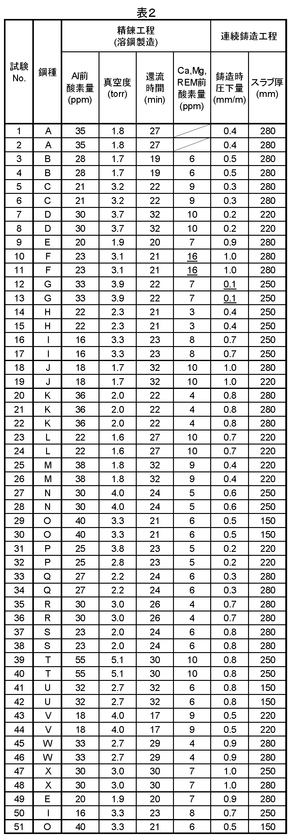
- a steel plate having a thickness of 5 to 50 mm was prototyped according to the manufacturing conditions shown in Tables 2 and 3.
- a descaling step was carried out between the heating step and the rolling step to remove the Fe-based oxide scale formed on the surface of the steel sheet.
- amount of oxygen before Ca, Mg, REM in Table 2 means the amount of dissolved oxygen before adding one or more selected from Ca, Mg and REM.
- the cooling rate (° C./s) in the column of cooling conditions in Table 3 is a cooling rate at 1/2 thickness obtained by heat conduction analysis by a known difference method from the measured surface temperature.
- Air cooling described in the cooling pattern column of Table 3 is an example of air cooling without water cooling (accelerated cooling), and “partially water cooling” is air cooling after rolling and then partially water cooling. This is an example of performing.
- the metallographic structure of the obtained steel sheet was observed, and the area ratio of each structure was measured. Specifically, first, in the rolling direction cross section of the steel sheet, when the width and thickness of the steel sheet are W and t, respectively, it is 1/4 W from the end face of the steel sheet and 1/4 t from the surface of the steel sheet. A test piece for observing the metallographic structure was cut out from the position.
- the rolling direction cross section (so-called L direction cross section) of the above test piece was subjected to nightl etching, and after etching, observation was performed with a visual field of 300 ⁇ m ⁇ 300 ⁇ m using an optical microscope.
- the area ratios of ferrite, pearlite, and bainite were determined by performing image analysis on the obtained microstructure photograph.
- the average aspect ratio and average grain size of ferrite were measured by the following procedure. Each ferrite identified in the field of view was ellipsically approximated by image analysis, and the aspect ratio of ferrite was obtained by dividing the major axis length by the minor axis length. Similarly, the area of each ferrite was determined by image analysis, and the diameter of a circle equal to this area was determined to determine the grain size of the ferrite. Then, the average aspect ratio and the average grain size were obtained by calculating the average values of the aspect ratio and the diameter of all the ferrites in the visual field, respectively.
- the total content (mass%) of the solid solution Mo and the solid solution W on the surface layer of the steel sheet was measured by the following procedure. First, two test pieces having a thickness of 1 mm were cut out from the surface of the steel sheet, and the contents of W and Mo in the test pieces were measured by using ICP emission spectroscopy for one of the test pieces.
- the contents of the solid solution W and the solid solution Mo were obtained by obtaining the difference between the contents of the W and Mo in the extraction residue from the contents of W and Mo in the test piece.
- the number density of coarse inclusions in the center of the plate thickness was measured. Specifically, particle analysis by SEM is performed on the number density of inclusions having a length of 5 ⁇ m or more existing in the region between the position 2/5 t from the surface of the steel sheet and the position 3/5 t from the surface of the steel sheet. Measured by.
- the region between the position of 2/5 t from the surface of the steel sheet and the position of 3/5 t from the surface of the steel sheet is measured by EPMA, the maximum value of P concentration is obtained, and the maximum concentration of P in the central portion is obtained.
- the measurement conditions were an accelerating voltage: 15 kV, a beam diameter: 20 ⁇ m, an irradiation time: 20 ms, and a measurement pitch: 20 ⁇ m.
- TS tensile strength
- YS yield stress
- t-EL total elongation
- ⁇ Corrosion test 1, 2> A test piece having a length of 40 mm in the rolling direction, a length of 40 mm in the width direction, and a length of 4 mm in the thickness direction was collected from the surface of the steel sheet. The cut surface (other than the surface) was coated with paint, and the iron oxide (scale) on the surface of the steel sheet was removed by wet polishing of No. 600 to prepare a test piece in which the base iron was exposed only on the surface of the 40 mm ⁇ 40 mm steel sheet.
- the immersion conditions were a liquid temperature of 30 ° C. and an immersion time of 24 hours to 4 weeks, and the corrosion weight loss was measured to evaluate the corrosion rate.
- the corrosive liquid composition simulates the environmental conditions when local corrosion occurs in an actual steel structure, and the rate of local corrosion progresses in the actual environment as the rate of corrosion in the corrosion test decreases. Will be done.
- ⁇ Corrosion test 3> A test piece having a length of 40 mm in the rolling direction, a length of 40 mm in the width direction, and a length of 4 mm in the thickness direction was collected from the surface of the steel sheet. The cut surface (other than the surface) was coated with paint, and the iron oxide (scale) on the surface of the steel sheet was removed by wet polishing of No. 600 to prepare a test piece in which the base iron was exposed only on the surface of the 40 mm ⁇ 40 mm steel sheet. Then, using the test piece, the corrosion rate and the sludge formation rate mainly composed of solid S were evaluated by the following procedure.
- an aqueous NaCl solution was applied to the surface of the test piece so that the amount of NaCl adhered was 1000 mg / m 2 , dried, and horizontally placed on a constant temperature heater plate in the test chamber. Then, a gas adjusted to a constant dew point (30 ° C.) was sent into the test chamber. Gas used is, CO 2: 12 vol%, H 2 S: 500ppm, O 2: 5 by volume%, N 2: having a composition the balance.
- test Nos. 1 to 16, 18, 20 to 32, 34 to 37, 39, 40 and 43 to 50 any corrosion It can be seen that the test also shows excellent corrosion resistance.
- test No. which satisfies all the above-mentioned suitable conditions. It can be seen that 15, 16, 18, 21-24, 26-31, 35 and 37 have a particularly excellent strength-ductility balance.
- Test No. In 17, 19, 33, 38, 41 and 42 the result was that the corrosion resistance was inferior.
- the test No. In Nos. 17 and 38 the O 2 concentration in the atmosphere during heating before hot spreading was low
- Test No. In 19 and 33 since the holding time at the time of heating was short, the formation of the scale was insufficient, and the concentration of Mo and W just below the scale was not sufficiently generated.
- test No. 41 and 42 steel U containing neither Mo nor W was used.
- the total contents of the solid solution Mo and the solid solution W in the surface layer portion of the steel sheet did not satisfy the provisions of the present invention, resulting in inferior corrosion resistance.
- Test No. which is a comparative example. In No. 51, since the heating time in the heating step was too long, the crystal grains became coarse and the strength-ductility balance deteriorated.
- the steel sheet according to the present invention it is possible to obtain a steel sheet having excellent corrosion resistance against corrosive gas components, salt and the like contained in crude oil. Therefore, the steel sheet according to the present invention can be suitably used for a crude oil tank.
Landscapes
- Chemical & Material Sciences (AREA)
- Engineering & Computer Science (AREA)
- Materials Engineering (AREA)
- Metallurgy (AREA)
- Organic Chemistry (AREA)
- Mechanical Engineering (AREA)
- Physics & Mathematics (AREA)
- Thermal Sciences (AREA)
- Crystallography & Structural Chemistry (AREA)
- Heat Treatment Of Steel (AREA)
- Heat Treatment Of Sheet Steel (AREA)
- Continuous Casting (AREA)
Abstract
Description
C :0.050~0.200%、
Si:0.100~1.000%、
Mn:0.50~2.00%、
P :0.030%以下、
S :0.010%以下、
Al:0.002~0.050%、
N :0.0010~0.0060%、
O :0.0005~0.0060%、
Ti:0.003~0.020%、
Cu:0.01~1.50%、
Ca:0~0.0080%、
Mg:0~0.0080%、
REM:0~0.0080%、
Mo:0~0.20%、
W :0~0.50%、
Nb:0~0.030%、
V :0~0.050%、
Ni:0~1.00%、
Cr:0~0.50%、
B :0~0.0030%、
Sb:0~0.30%、
Sn:0~0.30%、
Pb:0~0.30%、
As:0~0.30%、
Bi:0~0.30%、
Ta:0~0.50%、
Zr:0~0.50%、
残部:Feおよび不純物であり、
下記(i)式を満足し、
鋼板表層部における固溶Moおよび固溶Wの合計含有量が、質量%で、0.005%以上であり、
鋼板の圧延方向断面において、前記鋼板の厚さをtとした時に、前記鋼板の表面から1/4tの位置におけるフェライトの平均結晶粒径が60μm以下である、
鋼板。
0.01≦Mo+W≦0.70 ・・・(i)
但し、上記式中の元素記号は各元素の含有量(質量%)を表し、含まれない場合はゼロとする。
Si:0.200~1.000%、
P :0.015%以下、
S :0.003%以下、
であり、
下記(ii)式および(iii)式を満足し、
下記(iv)式で求められるフェライト変態開始温度Ar3が760~820℃であり、
前記鋼板の表面から1/4tの位置における金属組織が、面積%で、
パーライト:5~20%、
ベイナイト:10%以下、
残部:フェライトであり、
前記鋼板の表面から1/4tの位置におけるフェライトの平均アスペクト比が1.0~1.5であり、
前記鋼板の表面から1/4tの位置におけるフェライトの平均結晶粒径が5~20μmである、
上記(1)に記載の鋼板。
0.0005≦Ca+Mg+REM≦0.0080 ・・・(ii)
0.5≦Ti/N≦4.0 ・・・(iii)
Ar3=910-310×C+65×Si-80×Mn-20×Cu-55×Ni-15×Cr-80×Mo ・・・(iv)
但し、上記式中の元素記号は各元素の含有量(質量%)を表し、含まれない場合はゼロとする。
1mmピッチのビッカース硬さの試験で、前記鋼板の表面と、前記鋼板の表面から1/4tの位置との間の領域におけるビッカース硬さの平均値が、前記鋼板の表面から1/4tの位置と、前記鋼板の表面から3/4tの位置との間の領域におけるビッカース硬さの平均値の80~105%である、
上記(2)に記載の鋼板。
上記(1)から(3)までのいずれか1項に記載の鋼板。
上記(1)から(4)までのいずれか1項に記載の鋼板。
前記溶鋼を連続鋳造して、上記(1)に記載の化学組成を有する鋼片を製造する連続鋳造工程と、
得られた前記鋼片を加熱する加熱工程と、
加熱後の鋼片にデスケーリングを施すデスケーリング工程と、
デスケーリング後の鋼片に対して熱間圧延を施して鋼板とする熱間圧延工程と、
熱間圧延後の前記鋼板を室温まで冷却する冷却工程と、を備え、
前記加熱工程において、前記鋼片に対して、O2濃度が1.0体積%以上の雰囲気で、950℃以上1200℃未満の加熱温度で30~120分間保持し、加熱抽出温度を950℃以上1200℃未満とする、
鋼板の製造方法。
前記溶鋼を連続鋳造して、上記(2)に記載の化学組成を有する鋼片を製造する連続鋳造工程と、
得られた前記鋼片を加熱する加熱工程と、
加熱後の鋼片にデスケーリングを施すデスケーリング工程と、
デスケーリング後の鋼片に対して仕上圧延を含む熱間圧延を施して鋼板とする熱間圧延工程と、
熱間圧延後の前記鋼板を室温まで冷却する冷却工程と、を備え、
前記加熱工程において、前記鋼片に対して、O2濃度が1.0体積%以上の雰囲気で、950~1100℃の加熱温度で30~60分間保持し、加熱抽出温度を950~1100℃とし、
前記熱間圧延工程において、前記鋼片の表面温度がAr3-30℃~Trex℃の温度範囲内で、累積圧下率が50~75%となる条件で前記仕上圧延を行う、
鋼板の製造方法。
但し、Ar3は下記(iv)式で求められ、Trexは結晶粒の成長が始まる再結晶開始温度を意味し、下記(v)式で求められる。なお、下記式中の元素記号は各元素の含有量(質量%)を表す。
Ar3=910-310×C+65×Si-80×Mn-20×Cu-55×Ni-15×Cr-80×Mo ・・・(iv)
Trex=-91900[Nb*]2+9400[Nb*]+770 ・・・(v)
但し、下記(vi)式で求められる固溶Nb量(質量%)を、sol.Nbとした時に、
Nb≧sol.Nbの場合は、[Nb*]=sol.Nb
Nb<sol.Nbの場合は、[Nb*]=Nb
とする。
sol.Nb=(10(-6770/(T+273)+2.26))/(C+12/14×N) ・・・(vi)
なお、上記式中のTは鋼片の加熱抽出温度(℃)を表す。
上記(7)に記載の鋼板の製造方法。
上記(6)から(8)までのいずれか1項に記載の鋼板の製造方法。
上記(6)から(9)までのいずれか1項に記載の鋼板の製造方法。
各元素の限定理由は下記のとおりである。なお、以下の説明において含有量についての「%」は、「質量%」を意味する。
Cは、パーライトを形成して強度を高めるのに有効な元素である。一方、C含有量が過剰であると、溶接性および継手靭性の確保が困難となる。そのため、C含有量は0.050~0.200%とする。C含有量は0.070%以上または0.100%以上であるのが好ましく、0.180%以下または0.160%以下であるのが好ましい。
Siは、安価な脱酸元素であり、固溶強化に有効であるとともに、変態点を上昇させてα中の転位密度低減に寄与する。一方、Si含有量が過剰であると、溶接性および継手靭性を劣化させる。そのため、Si含有量は0.100~1.000%とする。優れた延性を得たい場合には、Si含有量は0.200%以上であるのが好ましく、0.300%以上であるのがより好ましい。また、Si含有量は0.800%以下であるのが好ましく、0.500%以下であるのが好ましい。
Mnは、母材の強度および靭性を向上させる元素として有効である。一方、Mn含有量が過剰であると、溶接性および継手靭性を劣化させる。そのため、Mn含有量は0.50~2.00%とする。Mn含有量は0.80%以上であるのが好ましく、0.90%以上であるのがより好ましい。また、Mn含有量は1.60%以下であるのが好ましく、1.50%以下であるのがより好ましい。
Pは、不純物として鋼中に含まれる元素であり、耐食性を確保するためには、0.030%以下とする。また、延性および靭性を確保するためには、P含有量は少ないほど望ましく、0.015%以下であるのが好ましい。
Sは、不純物として鋼中に含まれる元素であり、耐食性を確保するためには、0.010%以下とする。また、延性および靭性を確保するためには、S含有量は少ないほど望ましく、S含有量は0.003%以下であるのが好ましい。
Alは、重要な脱酸元素である。一方、Al含有量が過剰であると、鋼片の表面品位を損ない、靭性に有害な介在物を形成する。そのため、Al含有量は0.002~0.050%とする。Al含有量は0.010%以上であるのが好ましく、0.040%以下であるのが好ましい。
Nは、Alと共に窒化物を形成し継手靭性を向上させる。一方、N含有量が過剰であると、固溶Nによる脆化および伸び特性の低下が生じる。そのため、N含有量は0.0010~0.0060%とする。N含有量は0.0020%以上であるのが好ましく、0.0050%以下であるのが好ましく、0.0040%以下であるのがより好ましい。
Oは、後述するCa、Mg、REMとともに酸化物を形成する。O含有量が過剰であると、酸化物が粗大化して延性および靭性が低下する。一方、O含有量は少ないほどよいが、過度に低減するためには、例えば、RH真空脱ガス装置での還流作業が長時間となり現実的ではない。そのため、O含有量は0.0005~0.0060%とする。
Tiは、微量の含有により母材および溶接部の組織微細化を通じて靭性向上に寄与する。一方、Ti含有量が過剰であると、溶接部を硬化させ著しく靭性を劣化させる。そのため、Ti含有量は0.003~0.020%とする。Ti含有量は0.006%以上であるのが好ましく、0.013%以下であるのが好ましい。
0.5≦Ti/N≦4.0 ・・・(iii)
但し、上記式中の元素記号は各元素の含有量(質量%)を表す。
Cuは耐全面腐食性だけでなく、耐局部腐食性の向上に有効な元素である。さらに、固体Sの生成抑制にも効果がある。一方、Cu含有量が過剰であると、鋼片の表面割れの助長、継手靭性の劣化等、悪影響も顕在化する。そのため、Cu含有量は0.01~1.50%とする。Cu含有量は0.03%以上であるのが好ましく、0.50%以下であるのが好ましく、0.20%未満であるのがより好ましい。
Mg:0~0.0080%
REM:0~0.0080%
Ca、MgおよびREMは、いずれも硫化物を形成することで粗大な介在物(延伸MnS等)の生成を抑制するため、必要に応じて含有させてもよい。一方、いずれの含有量が0.0080%を超えても効果は飽和し、粗大な酸化物または硫化物を形成して靭性および伸びを劣化させる。そのため、Ca、MgおよびREMの含有量は、いずれも0.0080%以下とする。
0.0005≦Ca+Mg+REM≦0.0080 ・・・(ii)
但し、上記式中の元素記号は各元素の含有量(質量%)を表し、含まれない場合はゼロとする。
W :0~0.50%
MoおよびWは、耐局部腐食性の向上に有効な元素である。そのため、MoおよびWの少なくともいずれかを含有し、かつ合計含有量を0.01%以上とする必要がある。一方、Moは0.20%、Wは0.50%を超えて含有させると耐局部腐食性が逆に低下し、かつ溶接性や靭性を劣化させる。そのため、Mo含有量は0.20%以下、W含有量は0.50%以下とし、合計含有量を0.70%以下とする。すなわち、下記(i)式を満足する必要がある。
0.01≦Mo+W≦0.70 ・・・(i)
但し、上記式中の元素記号は各元素の含有量(質量%)を表し、含まれない場合はゼロとする。
Nbは、微量の添加により組織微細化に寄与し、母材強度確保に有効な元素であるため、必要に応じて含有させてもよい。一方、Nb含有量が過剰であると、溶接部を硬化させて著しく靭性を劣化させる。そのため、Nb含有量は0.030%以下とする。上記の効果を得たい場合には、Nb含有量は0.003%以上であるのが好ましい。
Vは、析出強化により強度上昇に寄与するため、必要に応じて含有させてもよい。一方、V含有量が過剰であると、継手靭性を損なうことがある。そのため、V含有量は0.050%以下とする。上記の効果を得たい場合には、V含有量は0.010%以上であるのが好ましい。
Niは、強度確保および靭性向上に有効であるため、必要に応じて含有させてもよい。一方、Ni含有量が過剰であると、コストが上昇する。そのため、Ni含有量は1.00%以下とする。上記の効果を得たい場合には、Ni含有量は0.05%以上であるのが好ましい。
Crは、焼入れ性を向上させ、高強度化に有効であるため、必要に応じて含有させてもよい。一方、Cr含有量が過剰であると、継手の硬さが上昇して靭性が低下することがある。そのため、Cr含有量は0.50%以下とする。上記の効果を得たい場合には、Cr含有量は0.05%以上であるのが好ましい。
Bは、微量添加により焼き入れ性を高め母材強度向上に寄与するため、必要に応じて含有させてもよい。一方、B含有量が過剰であると、伸びおよび継手靭性を劣化させる。そのため、B含有量は0.0030%以下とする。上記の効果を得たい場合には、B含有量は0.0003%以上であるのが好ましい。
Sn:0~0.30%
Pb:0~0.30%
As:0~0.30%
Bi:0~0.30%
Sb、Sn、Pb、AsおよびBiは、局部腐食の進展をさらに抑制する効果を有するため、必要に応じて含有させてもよい。一方、いずれの含有量が0.30%を超えても効果は飽和し、他の特性への悪影響の懸念もある。そのため、経済性も考慮して、Sb、Sn、Pb、AsおよびBiの含有量は、いずれも0.30%以下とする。また、いずれの元素の含有量も0.15%以下であるのが好ましい。上記の効果を得たい場合には、Sb:0.01%以上、Sn:0.01%以上、Pb:0.01%以上、As:0.01%以上およびBi:0.01%以上から選択される1種以上を含有させることが好ましい。
Zr:0~0.50%
TaおよびZrは、微量で鋼の強度を高めるのに有効な元素であり、主に強度調整のため、必要に応じて含有させてもよい。一方、いずれの含有量が0.50%を超えても、靭性劣化が顕著となる。そのため、TaおよびZrの含有量はいずれも0.50%以下とする。上記の効果を得たい場合には、Ta:0.005%以上およびZr:0.005%以上から選択される1種または2種を含有させることが好ましい。
本発明に係る鋼板においては、上述のように、耐食性の向上のため、MoおよびWを鋼板表層部に濃化させ、それにより、固溶するMoおよびWの量を所定値以上確保する。具体的には、鋼板表層部における固溶Moおよび固溶Wの合計含有量を、質量%で、0.005%以上とする。鋼板表層部における固溶Moおよび固溶Wの合計含有量は、0.010%以上であるのが好ましく、0.020%以上であるのがより好ましい。
Pは、連続鋳造時に中心偏析して板厚中心部に脆化域を形成し、割れを生じさせて局部伸びを劣化させるおそれがある。そのため、優れた延性を得たい場合には、板厚中心部におけるPの最大濃度は低い方が好ましく、具体的には、鋼板の表面から2/5tの位置と、鋼板の表面から3/5tの位置との間の領域における、Pの最大濃度を0.20%以下とすることが好ましい。また、Pの最大濃度を0.02%未満とすることは現実的に困難であるので、0.02%を下限とする。
本発明の鋼板の金属組織において、所定の伸び特性を確保する観点から、フェライトの平均結晶粒径を60μm以下とする。フェライトの平均結晶粒径は50μm以下であることが好ましい。なお、本発明において金属組織は、鋼板の圧延方向断面において、鋼板の幅および厚さをそれぞれWおよびtとしたときに、該鋼板の端面から1/4Wで、かつ、該鋼板の表面から1/4tの位置における組織をいうものとする。
強度特性である降伏応力および引張強さと伸び特性とは、相反する性質であって、両者を同時に向上させることは一般に困難とされている。伸び特性を確保しつつ、強度特性を確保するためには、パーライトの面積率は5~20%であることが好ましい。パーライトの面積率は10~15%であるのがより好ましい。
本発明において、金属組織はフェライトが主体であって、所定量のパーライトを含むことが好ましい。しかしながら、10%以下のベイナイトが含まれていても上述した効果を阻害しない。そのため、ベイナイトの面積率は10%以下であることが好ましく、5%以下であることがより好ましい。ベイナイトは含まれていなくてもよく、すなわち、ベイナイトの面積率は0%であってもよい。
フェライトは延性に優れた組織である。フェライトの面積率が高いほど、伸び特性ELを向上させることが可能となる。したがって、パーライトおよびベイナイト以外の組織はフェライトとする。
鋼板の表面から1/4tの位置におけるフェライトの平均アスペクト比は、低いほど好ましい。平均アスペクト比を1.5以下にすることで、転位密度を低下させ、伸びを向上させることができるようになる。そのため、平均アスペクト比は1.5以下であるのが好ましい。平均アスペクト比の下限は、フェライト粒が球状となる1.0である。
鋼板の表面から1/4tの位置におけるフェライトの平均結晶粒径を20μm以下とすることで、強度-延性バランスを向上させることができるようになる。そのため、平均結晶粒径は20μm以下であるのが好ましい。また、フェライト粒は細粒であるほど好ましいが5μm未満は工業上実現が難しいため、下限を5μmとした。
鋼板の表面から1/4tの位置におけるフェライト中の平均転位密度を低下させることで、フェライトが軟化し、より優れた伸び特性が得られるようになる。そのため、フェライト中の平均転位密度は7.0×1012/m2以下とすることが好ましい。転位密度は低ければ低いほどよいが、通常1.0×1012/m2を下回ることはほとんどない。平均転位密度の好ましい上限は6.0×1012/m2である。
ρ=2N/Ld ・・・(vii)
但し、上記式中の各記号の意味は以下のとおりである。
ρ:平均転位密度(/m2)
L:任意の直線の長さ(m)
N:任意の直線と転位線との交切点の数
d:薄膜試料の厚さ(m)
長さ5μm以上の粗大な介在物(MnS、アルミナ(Al2O3)等の硫化物または酸化物)は延性破壊(ボイド)の起点となり、局部伸びを劣化させることがある。そのため、優れた延性を得たい場合には、板厚中心部における粗大介在物の個数密度を低減することが好ましく、具体的には、鋼板の表面から2/5tの位置と、鋼板の表面から3/5tの位置との間の領域において存在する、長さ5μm以上の介在物の個数密度を10個/mm2以下とすることが好ましい。なお、介在物の測定は走査電子顕微鏡(SEM)による粒子解析によって行うものとする。
中央領域に対する表層領域のビッカース硬さの割合:80~105%
厚鋼板の冷却時において、鋼板の表面付近は板厚中心付近に比べて相対的に冷却速度が速くなり、硬質化しやすい。一方、表層部近傍の硬さを低く抑えることで伸び特性を改善することが可能となる。ここで、以下の説明では、鋼板の表面付近である、鋼板の表面と、鋼板の表面から1/4tの位置との間の領域を表層領域と呼び、板厚中心付近である、鋼板の表面から1/4tの位置と、鋼板の表面から3/4tの位置との間の領域を中央領域と呼ぶ。
本発明に係る鋼板の製造条件について特に制限はないが、後述する精錬工程、連続鋳造工程、加熱工程、デスケーリング工程、熱間圧延工程、および冷却工程を順に行うことで製造することができる。各工程について説明する。
精錬工程において溶鋼を製造する。精錬工程については公知の方法を採用すればよく、特に制限はない。しかしながら、鋼板の延性を向上させるためには、溶鋼を以下の手順により製造することが好ましい。
連続鋳造工程において溶鋼を連続鋳造し、上述した化学組成を有する鋼片を製造する。連続鋳造工程についても公知の方法を採用すればよく特に制限はない。しかしながら、鋼板の延性を向上させるためには、溶鋼を連続鋳造する際に、鋳片の凝固末期である鋳片の中心固相率が0.2~0.7の範囲において、鋳造ロールの間隙を、鋳造進行方向1mにつき0.2mm~3.0mmに狭めて圧下しながら鋳造することが好ましい。
鋼片に対して熱間圧延を施すために、鋼片を加熱する。加熱工程においては、上述した化学組成を有する鋼片に対して、O2濃度が1.0体積%以上の雰囲気において、950℃以上1200℃未満の加熱温度で30~120分間保持し、加熱抽出温度を950℃以上1200℃未満とする。
加熱した鋼片に対して、デスケーリングを行った後に、後述する熱間圧延を施す。デスケーリングを行うことで、鋼板の表面のFeを主体とした酸化スケールを除去し、酸化スケール直下のMoおよびWを、鋼片表層部に濃化させた状態で熱間圧延を施すことで、鋼板表層部に固溶Moおよび固溶Wを濃化させることができる。デスケーリング方法については上記の酸化スケールを除去可能な限りにおいて特に制限はなく、公知の方法を用いればよい。
熱間圧延工程において、鋼片に対して熱間圧延を施して鋼板とする。熱間圧延工程は、粗圧延および仕上圧延を含む。
Ar3=910-310×C+65×Si-80×Mn-20×Cu-55×Ni-15×Cr-80×Mo ・・・(iv)
但し、上記式中の元素記号は各元素の含有量(質量%)を表す。
Trex=-91900[Nb*]2+9400[Nb*]+770 ・・・(v)
Nb≧sol.Nbの場合は、[Nb*]=sol.Nb
Nb<sol.Nbの場合は、[Nb*]=Nb
とする。
sol.Nb=(10(-6770/(T+273)+2.26))/(C+12/14×N) ・・・(vi)
なお、上記式中のTは鋼片の加熱抽出温度(℃)を表す。
熱間圧延後の鋼板は、室温まで冷却する。耐食性に優れる鋼板を得るためには、冷却条件については特に制限はない。例えば、1℃/秒以下の平均冷却速度での空冷でもよいし、冷却水による冷却を行い、1℃/秒超の平均冷却速度での水冷をしてもよい。


ρ=2N/Ld ・・・(vii)
但し、上記式中の各記号の意味は以下のとおりである。
ρ:平均転位密度(/m2)
L:任意の直線の長さ(m)
N:任意の直線と転位線との交切点の数
d:薄膜試料の厚さ(m)
圧延方向に長さ40mm、幅方向に長さ40mm、厚さ方向に長さ4mmの試験片を鋼板の表面から採取した。切断面(表面以外)は塗料で被覆し、表面は600番の湿式研磨により、鋼板表面の酸化鉄(スケール)を取り除き、40mm×40mmの鋼板の表面だけ地鉄が露出した試験片とした。該試験片を、塩酸でpHを0.2に調整した20質量%NaCl水溶液(腐食試験1)、およびpHを0.5に調整した20質量%NaCl水溶液(腐食試験2)の2種類の腐食液中に浸漬した。
圧延方向に長さ40mm、幅方向に長さ40mm、厚さ方向に長さ4mmの試験片を鋼板の表面から採取した。切断面(表面以外)は塗料で被覆し、表面は600番の湿式研磨により、鋼板表面の酸化鉄(スケール)を取り除き、40mm×40mmの鋼板の表面だけ地鉄が露出した試験片とした。そして、当該試験片を用いて、腐食速度および固体Sを主体とするスラッジの生成速度を以下の手順で評価した。


Claims (10)
- 化学組成が、質量%で、
C :0.050~0.200%、
Si:0.100~1.000%、
Mn:0.50~2.00%、
P :0.030%以下、
S :0.010%以下、
Al:0.002~0.050%、
N :0.0010~0.0060%、
O :0.0005~0.0060%、
Ti:0.003~0.020%、
Cu:0.01~1.50%、
Ca:0~0.0080%、
Mg:0~0.0080%、
REM:0~0.0080%、
Mo:0~0.20%、
W :0~0.50%、
Nb:0~0.030%、
V :0~0.050%、
Ni:0~1.00%、
Cr:0~0.50%、
B :0~0.0030%、
Sb:0~0.30%、
Sn:0~0.30%、
Pb:0~0.30%、
As:0~0.30%、
Bi:0~0.30%、
Ta:0~0.50%、
Zr:0~0.50%、
残部:Feおよび不純物であり、
下記(i)式を満足し、
鋼板表層部における固溶Moおよび固溶Wの合計含有量が、質量%で、0.005%以上であり、
鋼板の圧延方向断面において、前記鋼板の厚さをtとした時に、前記鋼板の表面から1/4tの位置におけるフェライトの平均結晶粒径が60μm以下である、
鋼板。
0.01≦Mo+W≦0.70 ・・・(i)
但し、上記式中の元素記号は各元素の含有量(質量%)を表し、含まれない場合はゼロとする。 - 前記化学組成が、質量%で、
Si:0.200~1.000%、
P :0.015%以下、
S :0.003%以下、
であり、
下記(ii)式および(iii)式を満足し、
下記(iv)式で求められるフェライト変態開始温度Ar3が760~820℃であり、
前記鋼板の表面から1/4tの位置における金属組織が、面積%で、
パーライト:5~20%、
ベイナイト:10%以下、
残部:フェライトであり、
前記鋼板の表面から1/4tの位置におけるフェライトの平均アスペクト比が1.0~1.5であり、
前記鋼板の表面から1/4tの位置におけるフェライトの平均結晶粒径が5~20μmである、
請求項1に記載の鋼板。
0.0005≦Ca+Mg+REM≦0.0080 ・・・(ii)
0.5≦Ti/N≦4.0 ・・・(iii)
Ar3=910-310×C+65×Si-80×Mn-20×Cu-55×Ni-15×Cr-80×Mo ・・・(iv)
但し、上記式中の元素記号は各元素の含有量(質量%)を表し、含まれない場合はゼロとする。 - 前記鋼板の表面から1/4tの位置におけるフェライト中の平均転位密度が7.0×1012/m2以下であり、
1mmピッチのビッカース硬さの試験で、前記鋼板の表面と、前記鋼板の表面から1/4tの位置との間の領域におけるビッカース硬さの平均値が、前記鋼板の表面から1/4tの位置と、前記鋼板の表面から3/4tの位置との間の領域におけるビッカース硬さの平均値の80~105%である、
請求項2に記載の鋼板。 - 前記鋼板の表面から2/5tの位置と、前記鋼板の表面から3/5tの位置との間の領域において存在する、長さ5μm以上の介在物の個数密度が10個/mm2以下である、
請求項1から請求項3までのいずれか1項に記載の鋼板。 - 前記鋼板の表面から2/5tの位置と、前記鋼板の表面から3/5tの位置との間の領域における、Pの最大濃度が、質量%で、0.02~0.20%である、
請求項1から請求項4までのいずれか1項に記載の鋼板。 - 溶鋼を製造する精錬工程と、
前記溶鋼を連続鋳造して、請求項1に記載の化学組成を有する鋼片を製造する連続鋳造工程と、
得られた前記鋼片を加熱する加熱工程と、
加熱後の鋼片にデスケーリングを施すデスケーリング工程と、
デスケーリング後の鋼片に対して熱間圧延を施して鋼板とする熱間圧延工程と、
熱間圧延後の前記鋼板を室温まで冷却する冷却工程と、を備え、
前記加熱工程において、前記鋼片に対して、O2濃度が1.0体積%以上の雰囲気で、950℃以上1200℃未満の加熱温度で30~120分間保持し、加熱抽出温度を950℃以上1200℃未満とする、
鋼板の製造方法。 - 溶鋼を製造する精錬工程と、
前記溶鋼を連続鋳造して、請求項2に記載の化学組成を有する鋼片を製造する連続鋳造工程と、
得られた前記鋼片を加熱する加熱工程と、
加熱後の鋼片にデスケーリングを施すデスケーリング工程と、
デスケーリング後の鋼片に対して仕上圧延を含む熱間圧延を施して鋼板とする熱間圧延工程と、
熱間圧延後の前記鋼板を室温まで冷却する冷却工程と、を備え、
前記加熱工程において、前記鋼片に対して、O2濃度が1.0体積%以上の雰囲気で、950~1100℃の加熱温度で30~60分間保持し、加熱抽出温度を950~1100℃とし、
前記熱間圧延工程において、前記鋼片の表面温度がAr3-30℃~Trex℃の温度範囲内で、累積圧下率が50~75%となる条件で前記仕上圧延を行う、
鋼板の製造方法。
但し、Ar3は下記(iv)式で求められ、Trexは結晶粒の成長が始まる再結晶開始温度を意味し、下記(v)式で求められる。なお、下記式中の元素記号は各元素の含有量(質量%)を表す。
Ar3=910-310×C+65×Si-80×Mn-20×Cu-55×Ni-15×Cr-80×Mo ・・・(iv)
Trex=-91900[Nb*]2+9400[Nb*]+770 ・・・(v)
但し、下記(vi)式で求められる固溶Nb量(質量%)を、sol.Nbとした時に、
Nb≧sol.Nbの場合は、[Nb*]=sol.Nb
Nb<sol.Nbの場合は、[Nb*]=Nb
とする。
sol.Nb=(10(-6770/(T+273)+2.26))/(C+12/14×N) ・・・(vi)
なお、上記式中のTは鋼片の加熱抽出温度(℃)を表す。 - 前記冷却工程において、鋼板の表面温度がAr3-150℃~Ar3-50℃の温度まで、1℃/秒超、20℃/秒以下の平均冷却速度で水冷を行い、該水冷後、1℃/秒以下の平均冷却速度で空冷を行う、
請求項7に記載の鋼板の製造方法。 - 前記精錬工程において、真空脱ガス装置により溶鋼の溶存酸素量を40ppm以下に調整し、次いで、AlをAlの最終含有量が0.002~0.050%となるように添加して、溶鋼の溶存酸素量を10ppm以下に調整した後、Ca、MgおよびREMから選択される1種以上を、Ca、MgおよびREMの合計の最終含有量が0.0005~0.0080%となるように添加する、
請求項6から請求項8までのいずれか1項に記載の鋼板の製造方法。 - 前記連続鋳造工程において、鋳片の凝固末期である鋳片の中心固相率が0.2~0.7の範囲において、鋳造ロールの間隙を、鋳造進行方向1mにつき0.2mm~3.0mmに狭めて圧下しながら鋳造する、
請求項6から請求項9までのいずれか1項に記載の鋼板の製造方法。
Priority Applications (3)
| Application Number | Priority Date | Filing Date | Title |
|---|---|---|---|
| CN202080021699.3A CN113574197B (zh) | 2019-03-14 | 2020-03-12 | 钢板及其制造方法 |
| KR1020217033103A KR102376351B1 (ko) | 2019-03-14 | 2020-03-12 | 강판 및 그것의 제조 방법 |
| JP2021505143A JP7201068B2 (ja) | 2019-03-14 | 2020-03-12 | 鋼板およびその製造方法 |
Applications Claiming Priority (2)
| Application Number | Priority Date | Filing Date | Title |
|---|---|---|---|
| JP2019-047573 | 2019-03-14 | ||
| JP2019047573 | 2019-03-14 |
Publications (1)
| Publication Number | Publication Date |
|---|---|
| WO2020184683A1 true WO2020184683A1 (ja) | 2020-09-17 |
Family
ID=72426115
Family Applications (1)
| Application Number | Title | Priority Date | Filing Date |
|---|---|---|---|
| PCT/JP2020/010944 Ceased WO2020184683A1 (ja) | 2019-03-14 | 2020-03-12 | 鋼板およびその製造方法 |
Country Status (4)
| Country | Link |
|---|---|
| JP (1) | JP7201068B2 (ja) |
| KR (1) | KR102376351B1 (ja) |
| CN (1) | CN113574197B (ja) |
| WO (1) | WO2020184683A1 (ja) |
Cited By (11)
| Publication number | Priority date | Publication date | Assignee | Title |
|---|---|---|---|---|
| CN111485174A (zh) * | 2020-04-13 | 2020-08-04 | 攀钢集团攀枝花钢铁研究院有限公司 | 地铁用钢轨及其制备方法 |
| CN112267073A (zh) * | 2020-09-30 | 2021-01-26 | 东北大学 | 具有优异低温韧性和焊接性能的耐腐蚀磨损钢板及其制备方法 |
| WO2022145069A1 (ja) * | 2020-12-28 | 2022-07-07 | 日本製鉄株式会社 | 鋼材 |
| JP2023014929A (ja) * | 2021-07-19 | 2023-01-31 | Jfeスチール株式会社 | 鋼板およびその製造方法 |
| WO2023008163A1 (ja) * | 2021-07-27 | 2023-02-02 | 日本製鉄株式会社 | 鋼板およびその製造方法 |
| JP7323090B1 (ja) * | 2022-03-03 | 2023-08-08 | Jfeスチール株式会社 | 鋼板および鋼板の製造方法 |
| JP7323091B1 (ja) * | 2022-03-03 | 2023-08-08 | Jfeスチール株式会社 | 鋼板およびその製造方法 |
| JPWO2023162896A1 (ja) * | 2022-02-22 | 2023-08-31 | ||
| WO2023166934A1 (ja) * | 2022-03-03 | 2023-09-07 | Jfeスチール株式会社 | 鋼板およびその製造方法 |
| WO2023166935A1 (ja) * | 2022-03-03 | 2023-09-07 | Jfeスチール株式会社 | 鋼板および鋼板の製造方法 |
| JP2023130323A (ja) * | 2022-03-07 | 2023-09-20 | Jfeスチール株式会社 | 厚鋼板、構造物および厚鋼板の製造方法 |
Families Citing this family (2)
| Publication number | Priority date | Publication date | Assignee | Title |
|---|---|---|---|---|
| KR102882744B1 (ko) * | 2023-05-04 | 2025-11-07 | 현대제철 주식회사 | 표면 품질이 개선된 합금강 제조 방법 |
| CN119144901B (zh) * | 2024-09-27 | 2025-10-31 | 邯郸市永年区鑫魁工矿配件制造有限公司 | 一种耐腐蚀锚杆及其生产工艺 |
Citations (3)
| Publication number | Priority date | Publication date | Assignee | Title |
|---|---|---|---|---|
| JP2004204344A (ja) * | 2002-06-19 | 2004-07-22 | Nippon Steel Corp | 原油油槽用鋼およびその製造方法、原油油槽およびその防食方法 |
| JP2006137963A (ja) * | 2004-11-10 | 2006-06-01 | Sumitomo Metal Ind Ltd | 原油タンク用溶接継手及び原油タンク |
| JP2010196113A (ja) * | 2009-02-25 | 2010-09-09 | Jfe Steel Corp | 耐食性に優れた船舶用鋼材 |
Family Cites Families (4)
| Publication number | Priority date | Publication date | Assignee | Title |
|---|---|---|---|---|
| JP4898543B2 (ja) * | 2007-05-02 | 2012-03-14 | 株式会社神戸製鋼所 | 耐ピット性に優れた鋼板およびその製造方法 |
| JP6007968B2 (ja) * | 2014-12-26 | 2016-10-19 | 新日鐵住金株式会社 | 高強度高延性厚板鋼板とその製造方法 |
| JP6641875B2 (ja) * | 2015-10-21 | 2020-02-05 | 日本製鉄株式会社 | 低降伏比鋼板およびその製造方法 |
| KR102021815B1 (ko) * | 2018-03-16 | 2019-09-18 | 닛폰세이테츠 가부시키가이샤 | 석탄·광석 운반선 홀드용 강판 |
-
2020
- 2020-03-12 WO PCT/JP2020/010944 patent/WO2020184683A1/ja not_active Ceased
- 2020-03-12 JP JP2021505143A patent/JP7201068B2/ja active Active
- 2020-03-12 CN CN202080021699.3A patent/CN113574197B/zh active Active
- 2020-03-12 KR KR1020217033103A patent/KR102376351B1/ko active Active
Patent Citations (3)
| Publication number | Priority date | Publication date | Assignee | Title |
|---|---|---|---|---|
| JP2004204344A (ja) * | 2002-06-19 | 2004-07-22 | Nippon Steel Corp | 原油油槽用鋼およびその製造方法、原油油槽およびその防食方法 |
| JP2006137963A (ja) * | 2004-11-10 | 2006-06-01 | Sumitomo Metal Ind Ltd | 原油タンク用溶接継手及び原油タンク |
| JP2010196113A (ja) * | 2009-02-25 | 2010-09-09 | Jfe Steel Corp | 耐食性に優れた船舶用鋼材 |
Cited By (18)
| Publication number | Priority date | Publication date | Assignee | Title |
|---|---|---|---|---|
| CN111485174A (zh) * | 2020-04-13 | 2020-08-04 | 攀钢集团攀枝花钢铁研究院有限公司 | 地铁用钢轨及其制备方法 |
| CN112267073A (zh) * | 2020-09-30 | 2021-01-26 | 东北大学 | 具有优异低温韧性和焊接性能的耐腐蚀磨损钢板及其制备方法 |
| WO2022145069A1 (ja) * | 2020-12-28 | 2022-07-07 | 日本製鉄株式会社 | 鋼材 |
| JP2023014929A (ja) * | 2021-07-19 | 2023-01-31 | Jfeスチール株式会社 | 鋼板およびその製造方法 |
| JP7548148B2 (ja) | 2021-07-19 | 2024-09-10 | Jfeスチール株式会社 | 鋼板およびその製造方法 |
| KR20230155516A (ko) * | 2021-07-27 | 2023-11-10 | 닛폰세이테츠 가부시키가이샤 | 강판 및 그 제조 방법 |
| WO2023008163A1 (ja) * | 2021-07-27 | 2023-02-02 | 日本製鉄株式会社 | 鋼板およびその製造方法 |
| JP7277862B1 (ja) * | 2021-07-27 | 2023-05-19 | 日本製鉄株式会社 | 鋼板およびその製造方法 |
| KR102884405B1 (ko) | 2021-07-27 | 2025-11-12 | 닛폰세이테츠 가부시키가이샤 | 강판 및 그 제조 방법 |
| JPWO2023162896A1 (ja) * | 2022-02-22 | 2023-08-31 | ||
| WO2023162896A1 (ja) * | 2022-02-22 | 2023-08-31 | 日本製鉄株式会社 | 原油油槽用鋼材 |
| JP7769263B2 (ja) | 2022-02-22 | 2025-11-13 | 日本製鉄株式会社 | 原油油槽用鋼材 |
| WO2023166934A1 (ja) * | 2022-03-03 | 2023-09-07 | Jfeスチール株式会社 | 鋼板およびその製造方法 |
| WO2023166935A1 (ja) * | 2022-03-03 | 2023-09-07 | Jfeスチール株式会社 | 鋼板および鋼板の製造方法 |
| JP7323091B1 (ja) * | 2022-03-03 | 2023-08-08 | Jfeスチール株式会社 | 鋼板およびその製造方法 |
| JP7323090B1 (ja) * | 2022-03-03 | 2023-08-08 | Jfeスチール株式会社 | 鋼板および鋼板の製造方法 |
| JP2023130323A (ja) * | 2022-03-07 | 2023-09-20 | Jfeスチール株式会社 | 厚鋼板、構造物および厚鋼板の製造方法 |
| JP7635794B2 (ja) | 2022-03-07 | 2025-02-26 | Jfeスチール株式会社 | 厚鋼板、構造物および厚鋼板の製造方法 |
Also Published As
| Publication number | Publication date |
|---|---|
| KR102376351B1 (ko) | 2022-03-18 |
| CN113574197A (zh) | 2021-10-29 |
| JP7201068B2 (ja) | 2023-01-10 |
| JPWO2020184683A1 (ja) | 2021-12-16 |
| KR20210129236A (ko) | 2021-10-27 |
| CN113574197B (zh) | 2022-09-06 |
Similar Documents
| Publication | Publication Date | Title |
|---|---|---|
| JP7201068B2 (ja) | 鋼板およびその製造方法 | |
| US9109275B2 (en) | High-strength galvanized steel sheet and method of manufacturing the same | |
| KR102284770B1 (ko) | 가공성이 뛰어난 용융 Zn-Al-Mg계 도금 강판 및 그 제조 방법 | |
| US20200087764A1 (en) | High-strength steel sheet | |
| JP6418361B1 (ja) | 石炭・鉱石運搬船ホールド用鋼板 | |
| JP2016125077A (ja) | 高強度高延性厚板鋼板とその製造方法 | |
| TW201326422A (zh) | 高張力熱軋鋼板及其製造方法 | |
| JP6275510B2 (ja) | 高強度熱延鋼板およびその製造方法 | |
| WO2020158065A1 (ja) | 高強度鋼板およびその製造方法 | |
| EP2952600A1 (en) | High-strength hot-rolled steel sheet and production method thereof | |
| JP7277862B1 (ja) | 鋼板およびその製造方法 | |
| JP2006283131A (ja) | 塗膜密着性、加工性及び耐水素脆化特性に優れた高強度冷延鋼板並びに自動車用鋼部品 | |
| EP2952603A1 (en) | High-strength hot-rolled steel sheet and manufacturing process therefor | |
| KR20180120715A (ko) | 박 강판 및 도금 강판, 그리고, 열연 강판의 제조 방법, 냉연 풀 하드 강판의 제조 방법, 박 강판의 제조 방법 및 도금 강판의 제조 방법 | |
| CN116694988A (zh) | 薄钢板和镀覆钢板、以及薄钢板的制造方法和镀覆钢板的制造方法 | |
| CN116018416A (zh) | 钢板及其制造方法 | |
| JP5272412B2 (ja) | 高強度鋼板およびその製造方法 | |
| JP6320792B2 (ja) | 高強度熱延鋼板およびその製造方法 | |
| CN115443344B (zh) | 钢板及其制造方法 | |
| JP6610788B2 (ja) | 高強度熱延めっき鋼板 | |
| TW202012649A (zh) | 鋼板 | |
| JP2001355043A (ja) | 穴広げ性および延性が優れた高強度合金化溶融亜鉛めっき鋼板および高強度鋼板と、それらの製造方法 | |
| JP2015017322A (ja) | 加工性および靭性に優れた高強度熱延鋼板およびその製造方法 | |
| WO2023132344A1 (ja) | 鋼板およびその製造方法 | |
| WO2023281808A1 (ja) | 熱延鋼板 |
Legal Events
| Date | Code | Title | Description |
|---|---|---|---|
| 121 | Ep: the epo has been informed by wipo that ep was designated in this application |
Ref document number: 20769056 Country of ref document: EP Kind code of ref document: A1 |
|
| ENP | Entry into the national phase |
Ref document number: 2021505143 Country of ref document: JP Kind code of ref document: A |
|
| NENP | Non-entry into the national phase |
Ref country code: DE |
|
| ENP | Entry into the national phase |
Ref document number: 20217033103 Country of ref document: KR Kind code of ref document: A |
|
| 122 | Ep: pct application non-entry in european phase |
Ref document number: 20769056 Country of ref document: EP Kind code of ref document: A1 |