WO2020184424A1 - 液晶配向処理剤、液晶配向膜及び液晶表示素子 - Google Patents
液晶配向処理剤、液晶配向膜及び液晶表示素子 Download PDFInfo
- Publication number
- WO2020184424A1 WO2020184424A1 PCT/JP2020/009632 JP2020009632W WO2020184424A1 WO 2020184424 A1 WO2020184424 A1 WO 2020184424A1 JP 2020009632 W JP2020009632 W JP 2020009632W WO 2020184424 A1 WO2020184424 A1 WO 2020184424A1
- Authority
- WO
- WIPO (PCT)
- Prior art keywords
- liquid crystal
- crystal alignment
- treatment agent
- alignment treatment
- group
- Prior art date
- Legal status (The legal status is an assumption and is not a legal conclusion. Google has not performed a legal analysis and makes no representation as to the accuracy of the status listed.)
- Ceased
Links
- UHOVQNZJYSORNB-UHFFFAOYSA-N c1ccccc1 Chemical compound c1ccccc1 UHOVQNZJYSORNB-UHFFFAOYSA-N 0.000 description 3
- WFKDPJRCBCBQNT-UHFFFAOYSA-N CC(C(NC)=O)=C Chemical compound CC(C(NC)=O)=C WFKDPJRCBCBQNT-UHFFFAOYSA-N 0.000 description 1
- 0 CC(CNC(C=C(*)C(C)=O)=O)** Chemical compound CC(CNC(C=C(*)C(C)=O)=O)** 0.000 description 1
- JXEKYGKZWVEIEI-BCNFCOQCSA-N CC1(/C=C(\C)/N=C/C=C\C=C1)C(O)=O Chemical compound CC1(/C=C(\C)/N=C/C=C\C=C1)C(O)=O JXEKYGKZWVEIEI-BCNFCOQCSA-N 0.000 description 1
- ORCMKOFGYFOLIF-UHFFFAOYSA-N CC1=CC=CC=CC=N1 Chemical compound CC1=CC=CC=CC=N1 ORCMKOFGYFOLIF-UHFFFAOYSA-N 0.000 description 1
- FXWWAVREXBDOSP-UHFFFAOYSA-N CCC(CC1=C)OC1=O Chemical compound CCC(CC1=C)OC1=O FXWWAVREXBDOSP-UHFFFAOYSA-N 0.000 description 1
- WGESLFUSXZBFQF-UHFFFAOYSA-N CN(CC=C)CC=C Chemical compound CN(CC=C)CC=C WGESLFUSXZBFQF-UHFFFAOYSA-N 0.000 description 1
Classifications
-
- C—CHEMISTRY; METALLURGY
- C08—ORGANIC MACROMOLECULAR COMPOUNDS; THEIR PREPARATION OR CHEMICAL WORKING-UP; COMPOSITIONS BASED THEREON
- C08K—Use of inorganic or non-macromolecular organic substances as compounding ingredients
- C08K5/00—Use of organic ingredients
- C08K5/49—Phosphorus-containing compounds
- C08K5/51—Phosphorus bound to oxygen
- C08K5/52—Phosphorus bound to oxygen only
- C08K5/524—Esters of phosphorous acids, e.g. of H3PO3
-
- C—CHEMISTRY; METALLURGY
- C08—ORGANIC MACROMOLECULAR COMPOUNDS; THEIR PREPARATION OR CHEMICAL WORKING-UP; COMPOSITIONS BASED THEREON
- C08K—Use of inorganic or non-macromolecular organic substances as compounding ingredients
- C08K5/00—Use of organic ingredients
- C08K5/49—Phosphorus-containing compounds
- C08K5/51—Phosphorus bound to oxygen
- C08K5/53—Phosphorus bound to oxygen bound to oxygen and to carbon only
- C08K5/5317—Phosphonic compounds, e.g. R—P(:O)(OR')2
-
- C—CHEMISTRY; METALLURGY
- C08—ORGANIC MACROMOLECULAR COMPOUNDS; THEIR PREPARATION OR CHEMICAL WORKING-UP; COMPOSITIONS BASED THEREON
- C08L—COMPOSITIONS OF MACROMOLECULAR COMPOUNDS
- C08L79/00—Compositions of macromolecular compounds obtained by reactions forming in the main chain of the macromolecule a linkage containing nitrogen with or without oxygen or carbon only, not provided for in groups C08L61/00 - C08L77/00
- C08L79/04—Polycondensates having nitrogen-containing heterocyclic rings in the main chain; Polyhydrazides; Polyamide acids or similar polyimide precursors
- C08L79/08—Polyimides; Polyester-imides; Polyamide-imides; Polyamide acids or similar polyimide precursors
-
- C—CHEMISTRY; METALLURGY
- C08—ORGANIC MACROMOLECULAR COMPOUNDS; THEIR PREPARATION OR CHEMICAL WORKING-UP; COMPOSITIONS BASED THEREON
- C08L—COMPOSITIONS OF MACROMOLECULAR COMPOUNDS
- C08L83/00—Compositions of macromolecular compounds obtained by reactions forming in the main chain of the macromolecule a linkage containing silicon with or without sulfur, nitrogen, oxygen or carbon only; Compositions of derivatives of such polymers
- C08L83/04—Polysiloxanes
-
- G—PHYSICS
- G02—OPTICS
- G02F—OPTICAL DEVICES OR ARRANGEMENTS FOR THE CONTROL OF LIGHT BY MODIFICATION OF THE OPTICAL PROPERTIES OF THE MEDIA OF THE ELEMENTS INVOLVED THEREIN; NON-LINEAR OPTICS; FREQUENCY-CHANGING OF LIGHT; OPTICAL LOGIC ELEMENTS; OPTICAL ANALOGUE/DIGITAL CONVERTERS
- G02F1/00—Devices or arrangements for the control of the intensity, colour, phase, polarisation or direction of light arriving from an independent light source, e.g. switching, gating or modulating; Non-linear optics
- G02F1/01—Devices or arrangements for the control of the intensity, colour, phase, polarisation or direction of light arriving from an independent light source, e.g. switching, gating or modulating; Non-linear optics for the control of the intensity, phase, polarisation or colour
- G02F1/13—Devices or arrangements for the control of the intensity, colour, phase, polarisation or direction of light arriving from an independent light source, e.g. switching, gating or modulating; Non-linear optics for the control of the intensity, phase, polarisation or colour based on liquid crystals, e.g. single liquid crystal display cells
-
- G—PHYSICS
- G02—OPTICS
- G02F—OPTICAL DEVICES OR ARRANGEMENTS FOR THE CONTROL OF LIGHT BY MODIFICATION OF THE OPTICAL PROPERTIES OF THE MEDIA OF THE ELEMENTS INVOLVED THEREIN; NON-LINEAR OPTICS; FREQUENCY-CHANGING OF LIGHT; OPTICAL LOGIC ELEMENTS; OPTICAL ANALOGUE/DIGITAL CONVERTERS
- G02F1/00—Devices or arrangements for the control of the intensity, colour, phase, polarisation or direction of light arriving from an independent light source, e.g. switching, gating or modulating; Non-linear optics
- G02F1/01—Devices or arrangements for the control of the intensity, colour, phase, polarisation or direction of light arriving from an independent light source, e.g. switching, gating or modulating; Non-linear optics for the control of the intensity, phase, polarisation or colour
- G02F1/13—Devices or arrangements for the control of the intensity, colour, phase, polarisation or direction of light arriving from an independent light source, e.g. switching, gating or modulating; Non-linear optics for the control of the intensity, phase, polarisation or colour based on liquid crystals, e.g. single liquid crystal display cells
- G02F1/133—Constructional arrangements; Operation of liquid crystal cells; Circuit arrangements
- G02F1/1333—Constructional arrangements; Manufacturing methods
- G02F1/1337—Surface-induced orientation of the liquid crystal molecules, e.g. by alignment layers
-
- G—PHYSICS
- G02—OPTICS
- G02F—OPTICAL DEVICES OR ARRANGEMENTS FOR THE CONTROL OF LIGHT BY MODIFICATION OF THE OPTICAL PROPERTIES OF THE MEDIA OF THE ELEMENTS INVOLVED THEREIN; NON-LINEAR OPTICS; FREQUENCY-CHANGING OF LIGHT; OPTICAL LOGIC ELEMENTS; OPTICAL ANALOGUE/DIGITAL CONVERTERS
- G02F1/00—Devices or arrangements for the control of the intensity, colour, phase, polarisation or direction of light arriving from an independent light source, e.g. switching, gating or modulating; Non-linear optics
- G02F1/01—Devices or arrangements for the control of the intensity, colour, phase, polarisation or direction of light arriving from an independent light source, e.g. switching, gating or modulating; Non-linear optics for the control of the intensity, phase, polarisation or colour
- G02F1/13—Devices or arrangements for the control of the intensity, colour, phase, polarisation or direction of light arriving from an independent light source, e.g. switching, gating or modulating; Non-linear optics for the control of the intensity, phase, polarisation or colour based on liquid crystals, e.g. single liquid crystal display cells
- G02F1/133—Constructional arrangements; Operation of liquid crystal cells; Circuit arrangements
- G02F1/1333—Constructional arrangements; Manufacturing methods
- G02F1/1337—Surface-induced orientation of the liquid crystal molecules, e.g. by alignment layers
- G02F1/133703—Surface-induced orientation of the liquid crystal molecules, e.g. by alignment layers by introducing organic surfactant additives into the liquid crystal material
Definitions
- the present invention relates to a liquid crystal alignment treatment agent used in the manufacture of a liquid crystal display element, a liquid crystal alignment film obtained from the liquid crystal alignment treatment agent, and a liquid crystal display element using the liquid crystal alignment film.
- Films made of organic materials such as polymer materials have attracted attention for their ease of formation and insulating performance, and are widely used as interlayer insulating films, protective films, and the like in electronic devices.
- a liquid crystal display element which is well known as a display device
- an organic film made of polyimide is used as a liquid crystal alignment film.
- the liquid crystal alignment film is used for the purpose of controlling the alignment state of the liquid crystal.
- it is required to reduce the contrast of the liquid crystal display element and suppress the display defect due to long-term use.
- the liquid crystal alignment film using polyimide as a method of improving the liquid crystal alignment and making it difficult for display defects to occur in the peripheral portion of the liquid crystal display screen, the liquid crystal alignment using a liquid crystal alignment treatment agent to which an alkoxysilane compound is added is used.
- a membrane has been proposed (see, for example, Patent Document 1 or Patent Document 2).
- liquid crystal display elements have been used for mobile applications such as smartphones and mobile phones.
- the drawing position of the sealant be set to a position in contact with the edge of the liquid crystal alignment film having weak adhesiveness to the sealant, or to be the upper part of the liquid crystal alignment film. Therefore, in recent years, the adhesion between the substrates of the liquid crystal display element has become weaker than in the past.
- the present invention has excellent storage stability of the liquid crystal alignment treatment agent, high adhesiveness (also referred to as adhesion) between the substrates of the liquid crystal display element, and is further exposed to high temperature and high humidity for a long time. It is an object of the present invention to provide a liquid crystal alignment film capable of suppressing the generation of air bubbles in the liquid crystal display element and the peeling of the element even in such an environment. In addition, it is also an object to provide a liquid crystal display element having the above liquid crystal alignment film and a liquid crystal alignment treatment agent capable of providing the above liquid crystal alignment film.
- the present inventor has completed the present invention having the following gist. That is, it is a liquid crystal alignment treatment agent containing the following components (A) and (B).
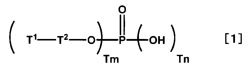
- Component (A) Compound of the following formula [1] (also referred to as a specific compound)
- T 1 represents the following formula [1-a] or formula [1-b].
- T 2 represents an alkylene group having 2 to 24 carbon atoms, and in the alkylene group, any -CH 2 -that is not adjacent to T 1 and O is -O-, -CO-, -COO-, -OCO. -, -CONH-, -NHCO-, -NH- or -CON (CH 3 )-may be substituted.
- Tm represents an integer of 1 to 2.
- Tn represents an integer of 1 to 2. However, Tm + Tn is 3.
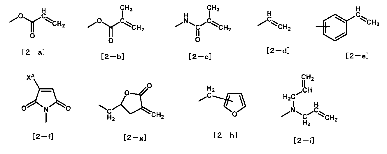
- X A represents a hydrogen atom or a benzene ring.
- the liquid crystal alignment treatment agent of the present invention has excellent storage stability, and the liquid crystal display element using the liquid crystal alignment treatment agent generates bubbles in the liquid crystal display element and causes the element even in a harsh environment exposed to high temperature and high humidity for a long time. Peeling can be suppressed.
- the mechanism by which the liquid crystal display element having the above-mentioned excellent characteristics is obtained by the present invention is not necessarily clear, but it is presumed as follows. Since the specific compound has a phosphoric acid group that strongly interacts with the metal, the liquid crystal alignment film obtained from the liquid crystal alignment treatment agent containing the specific compound has high adhesion to a metal electrode such as an ITO electrode.
- the structure of T 1 in the above formula [1] of the specific compound can react with the specific structure in the specific polymer by ultraviolet rays or heat. Therefore, the specific compound having high adhesion to the metal electrode can be chemically bonded to the specific polymer that is the base of the liquid crystal alignment film. As a result, the adhesion between the liquid crystal alignment film and the metal electrode can be improved as compared with the conventional method of adding a low molecular weight compound capable of increasing the adhesion to the metal electrode to the liquid crystal alignment treatment agent. It is thought that it can be made higher.
- the specific structure in the specific polymer reacts with ultraviolet rays, it can be combined with the reactive group of the polymerizable compound in the sealant by curing the sealant at the time of manufacturing the liquid crystal display element, specifically, by irradiating with ultraviolet rays. It reacts and the adhesion between the liquid crystal alignment film and the sealant becomes strong.
- the liquid crystal display element using the liquid crystal alignment treatment agent containing the specific compound and the specific polymer has high adhesion between the liquid crystal alignment film and the metal electrode and the liquid crystal alignment film and the sealant after forming the liquid crystal alignment film.
- the liquid crystal display element of the present invention can be used for a liquid crystal display element of a smartphone, a mobile phone, or the like.
- the specific compound is a compound of the above formula [1].
- T 1 , T 2 , Tm and Tn are as defined above, but the following are preferable.
- the formula [1-a] or the formula [1-b] is preferable for T 1 .
- T 2 is preferably an alkylene group having 2 to 12 carbon atoms, and any -CH 2- that is not adjacent to T 1 and O may be substituted with -O-, -COO- or -OCO-.
- Tm is preferably an integer of 1 to 2.
- Tn is preferably an integer of 1 to 2.
- Tm + Tn is 3.
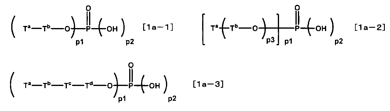
- Specific specific compounds include compounds of the following formulas [1a-1] to [1a-3], and it is preferable to use these.
- T a respectively, the formula [1-a] or an equation [1-b].
- Each T b represents an alkylene group having 2 to 18 carbon atoms.
- T c represents -COO- or -OCO-.
- T d represents an alkylene group having 2 to 12 carbon atoms.
- p1 represents an integer of 1 to 2, respectively.
- p2 represents an integer of 1 to 2, respectively.
- p1 + p2 is 3.
- p3 represents an integer of 2 to 8.
- Hosmer-M, Hosmer-PE, Hosma-PP manufactured by DAP
- Light Acrylate P-1A N
- Light Ester P-1M manufactured by Kyoei Kagaku Co., Ltd.
- KAYAMER PM-2 And KAYAMER PM-21 all manufactured by Nippon Kayaku Co., Ltd.
- the ratio of the specific compound used is preferably 0.01 to 20 parts by mass with respect to 100 parts by mass of all the polymers in the liquid crystal alignment treatment agent from the viewpoint of adhesion between the liquid crystal alignment film of the liquid crystal display element and the electrode. .. More preferably, it is 0.05 to 10 parts by mass. Particularly preferred is 0.1 to 10 parts by mass.
- the specific compound may be used alone or in combination of two or more depending on each property.
- the specific structure is at least one structure selected from the above formulas [2-a] to [2-i]. Of these, the formulas [2-a] to [2-c], the formula [2-e], the formula [2-h], or the formula [2-i] are preferable. More preferred are formulas [2-a], formulas [2-b], formulas [2-h] or formulas [2-i].
- the specific polymer having a specific structure is not particularly limited, but at least one weight selected from acrylic polymer, methacrylic polymer, novolak resin, polyhydroxystyrene, polyimide precursor, polyimide, polyamide, polyester, cellulose or polysiloxane.
- Coalescence is preferred. More preferred are polyimide precursors, polyimides or polysiloxanes.
- the specific structure is preferably in a form contained in the repeating unit constituting the polymer.
- the repeating unit containing the specific structure preferably contains 10 to 70 mol%, more preferably 20 to 60 mol%, based on the total repeating units constituting the polymer.
- the specific polymer having a specific structure may be used alone or in combination of two or more types depending on each property.
- a polyimide precursor or a polyimide (generally referred to as a polyimide-based polymer)
- they are preferably a polyimide precursor or a polyimide obtained by reacting a diamine component with a tetracarboxylic acid component.
- the polyimide-based polymer may be used alone or in combination of two or more, depending on each characteristic.
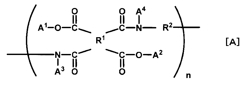
- the polyimide precursor has, for example, the structure of the following formula [A].
- R 1 represents a tetravalent organic group.
- R 2 represents a divalent organic group.
- a 1 and A 2 each represent a hydrogen atom or an alkyl group having 1 to 8 carbon atoms.
- a 3 and A 4 represent a hydrogen atom, an alkyl group having 1 to 5 carbon atoms, or an acetyl group, respectively.
- n represents a positive integer.
- the diamine component is a diamine having two primary or secondary amino groups in the molecule
- the tetracarboxylic acid component is a tetracarboxylic acid compound, a tetracarboxylic dianhydride, or a tetracarboxylic dianhydride compound.
- the polyimide-based polymer has the following formula [D] because it can be obtained relatively easily by using the tetracarboxylic acid dianhydride of the following formula [B] and the diamine of the following formula [C] as raw materials.
- a polyamic acid having a structural formula of a repeating unit or a polyimide obtained by imidizing the polyamic acid is preferable.
- R 1 and R 2 are the same as those defined by the formula [A].
- R 1 and R 2 are the same as those defined by the formula [A].
- an alkyl group having 1 to 8 carbon atoms of A 1 and A 2 in the formula [A] and an alkyl group having 1 to 8 carbon atoms in the formula [A] are added.
- Alkyl groups or acetyl groups having 1 to 5 carbon atoms of A 3 and A 4 can also be introduced.
- a method for introducing a specific structure into a polyimide-based polymer it is preferable to use a diamine having a specific structure as a part of a raw material.
- a diamine having the structure of the following formula [2] also referred to as a specific diamine).
- X 1 is a single bond, -O-, -NH-, -N (CH 3 )-, -CH 2 O-, -CONH-, -NHCO-, -CON (CH 3 )-, -N (CH 3). ) Indicates CO-, -COO- or -OCO-. Of these, single bonds, -O-, -CH 2 O-, -CONH-, -COO- or -OCO- are preferable. More preferred are single bonds, -O-, -CH 2 O- or -COO-.
- X 2 represents an organic group having 6 to 24 carbon atoms having a single bond, an alkylene group having 1 to 18 carbon atoms, or a cyclic group selected from a benzene ring, a cyclohexane ring and a heterocyclic ring, and any of these cyclic groups.
- the hydrogen atom is substituted with an alkyl group having 1 to 3 carbon atoms, an alkoxyl group having 1 to 3 carbon atoms, a fluorine-containing alkyl group having 1 to 3 carbon atoms, a fluorine-containing alkoxyl group having 1 to 3 carbon atoms or a fluorine atom. You may.
- a single bond, an alkylene group having 1 to 12 carbon atoms, a benzene ring or a cyclohexane ring is preferable. More preferred are single bonds or alkylene groups with 1-12 carbon atoms.
- X 3 is a single bond, -O-, -NH-, -N (CH 3 )-, -CH 2 O-, -CONH-, -NHCO-, -CON (CH 3 )-, -N (CH 3). ) Indicates CO-, -COO- or -OCO-. Of these, single bonds, -O-, -COO- or -OCO- are preferable. More preferred are single bonds or -OCO-.
- X 4 represents any of the above formulas [2-a] to [2-i]. Of these, formulas [2-a] to [2-e], formulas [2-h] or formulas [2-i] are preferable. More preferred are formulas [2-a], formulas [2-b], formulas [2-d], formulas [2-e] or formulas [2-i]. Particularly preferred are formulas [2-a], formulas [2-b] or formulas [2-i]. Xm represents an integer of 1 to 4. Of these, 1 or 2 is preferable.
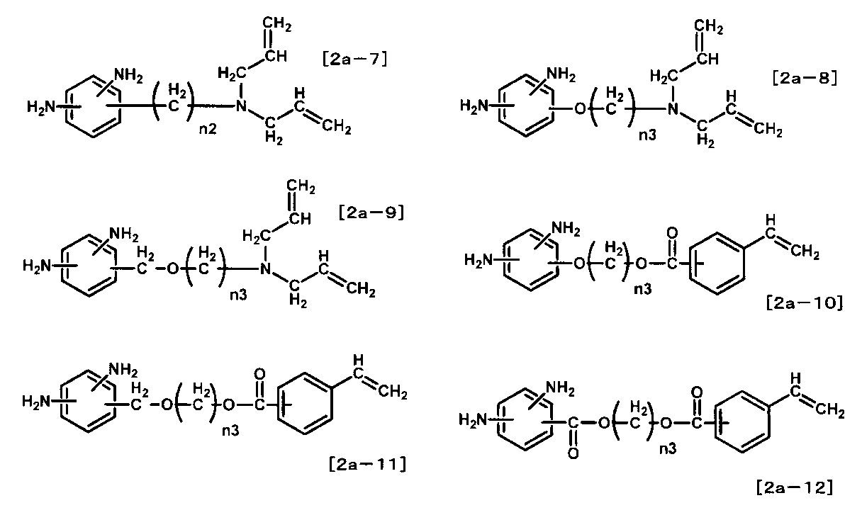
- X represents the formula [2]. Further, X 1 ⁇ X 4 and Xm details in the formula [2], and preferred combinations are as in formula [2]. Xn represents an integer of 1 to 4. Of these, 1 is preferable. More specific specific diamines include the following formulas [2a-1] to [2a-12], and it is preferable to use these.
- N1 represents an integer of 1 to 12, respectively.
- n2 represents an integer from 0 to 12.
- n3 represents an integer of 2 to 12, respectively.
- formulas [2a-1], formulas [2a-2], formulas [2a-5] to [2a-7], formulas [2a-11] or formulas [2a-12] are preferable. More preferred are formulas [2a-5] to [2a-7], formulas [2a-11] or formulas [2a-12].
- the ratio of the specific diamine used is preferably 10 to 70 mol% with respect to the entire diamine component from the viewpoint of adhesion between the liquid crystal alignment film of the liquid crystal display element and the sealant. More preferred is 20-60 mol%.
- the specific diamine one type or a mixture of two or more types can be used depending on each characteristic.
- the diamine component for producing the polyimide-based polymer may include a diamine other than the specific diamine (also referred to as other diamine).
- a diamine other than the specific diamine also referred to as other diamine.
- These diamine components can be used alone or in admixture of two or more depending on each characteristic.
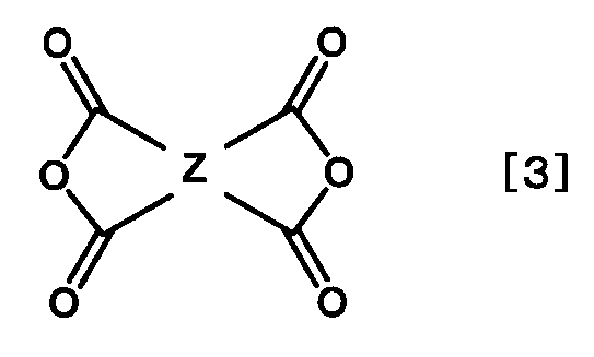
- tetracarboxylic acid component for producing a polyimide-based polymer examples include the tetracarboxylic dianhydride of the following formula [3], its tetracarboxylic acid derivative tetracarboxylic acid, the tetracarboxylic acid dihalide compound, and the tetracarboxylic acid. It is preferable to use a dialkyl ester compound or a tetracarboxylic acid dialkyl ester dihalide compound (all of which are also collectively referred to as a specific tetracarboxylic acid component).
- Z represents any of the following formulas [3a] to [3l].
- Z A to Z D represent a hydrogen atom, a methyl group, a chlorine atom or a benzene ring, respectively.
- Each Z E and Z F represents a hydrogen atom or a methyl group.
- the formula [3a], the formula [3c], the formula [3d], the formula [3e], the formula [3f], the formula [3g], the formula [3k] or the formula [3l] are preferable. .. More preferred are formulas [3a], formulas [3e], formulas [3f], formulas [3g], formulas [3k] or formulas [3l]. Particularly preferred are formulas [3a], formulas [3e], formulas [3f], formulas [3g] or formulas [3l].
- the ratio of the specific tetracarboxylic acid component used is preferably 1 mol% or more based on the total tetracarboxylic acid component. More preferably, it is 5 mol% or more. Particularly preferred is 10 mol% or more. Most preferred is 10-90 mol%.
- tetracarboxylic acid components other than the specific tetracarboxylic acid component can be used.
- examples of other tetracarboxylic acid components include the following tetracarboxylic acid compounds, tetracarboxylic dianhydrides, dicarboxylic acid dihalides compounds, dicarboxylic acid dialkyl ester compounds and dialkyl ester dihalide compounds. Specific examples thereof include other tetracarboxylic acid components described on pages 34 to 35 of International Publication WO 2015/012368 (published on January 29, 2015).
- the specific tetracarboxylic acid component and other tetracarboxylic acid components may be used alone or in admixture of two or more, depending on each property.
- the method for synthesizing the polyimide polymer is not particularly limited. It is usually obtained by reacting a diamine component with a tetracarboxylic acid component. Specifically, the method described on pages 46 to 50 of International Publication WO2016 / 076412 (published on May 19, 2016) can be mentioned.
- the reaction between the diamine component and the tetracarboxylic acid component is usually carried out in a solvent containing the diamine component and the tetracarboxylic acid component.
- the solvent used at that time is not particularly limited as long as it dissolves the produced polyimide precursor.
- N-methyl-2-pyrrolidone, N-ethyl-2-pyrrolidone, ⁇ -butyrolactone, N, N-dimethylformamide, N, N-dimethylacetamide, dimethyl sulfoxide or 1,3-dimethyl-2- Examples include imidazolidinone.
- the polyimide precursor has high solvent solubility, methyl ethyl ketone, cyclohexanone, cyclopentanone, 4-hydroxy-4-methyl-2-pentanone or a solvent of the following formulas [D1] to [D3] may be used. it can.
- D 1 and D 2 represent alkyl groups having 1 to 3 carbon atoms.
- D 3 represents an alkyl group having 1 to 4 carbon atoms. Further, these may be used alone or in combination. Further, even if the solvent does not dissolve the polyimide precursor, it may be mixed with the above solvent and used as long as the produced polyimide precursor does not precipitate. Further, since the water content in the organic solvent inhibits the polymerization reaction and further causes the produced polyimide precursor to be hydrolyzed, it is preferable to use a dehydrated and dried organic solvent. In the polymerization reaction of the polyimide precursor, the total number of moles of the tetracarboxylic acid component when the total number of moles of the diamine component is 1.0 is preferably 0.8 to 1.2.
- Polyimide is obtained by ring-closing a polyimide precursor.
- the ring closure rate (also referred to as imidization rate) of the amic acid group does not necessarily have to be 100%, and can be arbitrarily adjusted according to the application and purpose. Of these, 30 to 80% is preferable from the viewpoint of solubility of the polyimide-based polymer in a solvent. More preferred is 40-70%.
- the molecular weight of the polyimide-based polymer is 5 by weight average molecular weight measured by the GPC (Gel Permeation Chromatography) method, considering the strength of the liquid crystal alignment film obtained from the polyimide-based polymer, workability at the time of forming the liquid crystal alignment film, and coating film property. It is preferably 3,000 to 1,000,000, more preferably 10,000 to 150,000.
- polysiloxane also referred to as a polysiloxane-based polymer
- polysiloxane obtained by polycondensing the alkoxysilane of the following formula [A1], or the alkoxysilane of the formula [A1] and the following formula It is preferable to use a polysiloxane obtained by polycondensing with the alkoxysilane of [A2].
- a 1 represents an organic group having at least one structure selected from the above formulas [2-a] to [2-i] and having 2 to 12 carbon atoms. Of these, formulas [2-a] to [2-e], formulas [2-h] or formulas [2-i] are preferable. More preferred are formulas [2-a], formulas [2-b], formulas [2-d], formulas [2-e] or formulas [2-i]. Particularly preferred is the formula [2-a] or the formula [2-b].
- a 2 represents a hydrogen atom or an alkyl group having 1 to 5 carbon atoms. Of these, a hydrogen atom or an alkyl group having 1 to 3 carbon atoms is preferable.
- a 3 represents an alkyl group having 1 to 5 carbon atoms. Of these, an alkyl group having 1 to 3 carbon atoms is preferable.
- n represents an integer of 0 to 2. Of these, 1 is preferable.
- p represents an integer of 0 to 3. Of these, 1 to 3 are preferable. More preferred is 2 or 3.
- m + n + p is 4.
- Specific examples of the alkoxysilane of the formula [A1] include the following.
- allyltriethoxysilane allyltrimethoxysilane, diethoxymethylvinylsilane, dimethoxymethylvinylsilane, triethoxyvinylsilane, vinyltrimethoxysilane, vinyltris (2-methoxyethoxy) silane, 3- (triethoxysilyl) propylmethacrylate, 3 -(Trimethoxysilyl) propylacrylate or 3- (trimethoxysilyl) propylmethacrylate, and it is preferable to use these.
- alkoxysilane of the formula [A1] can be used by one kind or a mixture of two or more kinds depending on each characteristic.
- B 1 represents a hydrogen atom or an alkyl group having 1 to 5 carbon atoms. Of these, a hydrogen atom or an alkyl group having 1 to 3 carbon atoms is preferable.
- B 2 represents an alkyl group having 1 to 5 carbon atoms. Of these, an alkyl group having 1 to 3 carbon atoms is preferable.
- n represents an integer of 0 to 3.
- alkoxysilane of the formula [A2] include the alkoxysilane of the formula [2c] described on pages 24 to 25 of International Publication WO2015 / 008846 (published on 2015.1.22).
- examples of the alkoxysilane in which n is 0 include tetramethoxysilane, tetraethoxysilane, tetrapropoxysilane and tetrabutoxysilane, and examples of the alkoxysilane in the formula [A2] include these alkoxysilanes. It is preferable to use silane.
- the alkoxysilane of the formula [A2] can be used by one type or a mixture of two or more types depending on each characteristic.
- polysiloxane obtained by polycondensing a plurality of types of alkoxysilanes is preferable from the viewpoint of polycondensation reactivity and solubility of the polysiloxane-based polymer in a solvent. That is, it is preferable to use a polysiloxane obtained by polycondensing two types of alkoxysilanes of the formula [A1] and the formula [A2].
- the proportion of the alkoxysilane of the formula [A1] is preferably 1 to 70 mol% in all the alkoxysilanes. Of these, 1 to 50 mol% is preferable. More preferably, it is 1 to 30 mol%.
- the proportion of the alkoxysilane of the formula [A2] is preferably 30 to 99 mol% of all the alkoxysilanes. Of these, 50 to 99 mol% is preferable. More preferred is 70-99 mol%.
- the method for polycondensing the polysiloxane polymer is not particularly limited. Specific examples thereof include the methods described on pages 26 to 29 of the International Publication WO2015 / 008846 (published on January 22, 2015).
- the reaction may be carried out using a mixture of a plurality of types of alkoxysilanes mixed in advance.
- the reaction may be carried out while sequentially adding a plurality of types of alkoxysilanes.
- the solution of the polysiloxane-based polymer obtained by the above method may be used as it is as the specific polymer, or if necessary, the solution of the polysiloxane-based polymer obtained by the above method may be used. It may be concentrated, diluted by adding a solvent, or replaced with another solvent to be used as a specific polymer.
- the polysiloxane-based polymer may be used alone or in combination of two or more, depending on each property.
- the solvent used for dilution may be a solvent used for the polycondensation reaction or another solvent.
- the additive solvent is not particularly limited as long as the polysiloxane-based polymer is uniformly dissolved, and one type or two or more types can be arbitrarily selected.
- examples of such an additive solvent include a ketone solvent such as acetone, methyl ethyl ketone and methyl isobutyl ketone, and an ester solvent such as methyl acetate, ethyl acetate and ethyl lactate in addition to the solvent used for the polycondensation reaction. ..
- the liquid crystal alignment treatment agent contains a specific compound and a specific polymer, and is preferably a solution for forming a liquid crystal alignment film, and is a solution containing a specific compound, a specific polymer, and a solvent. At that time, two or more kinds of specific compounds and specific polymers can be used, respectively.
- the content of the polymer component in the liquid crystal alignment treatment agent of the present invention can be appropriately changed by setting the thickness of the liquid crystal alignment film to be formed, but the point is that a uniform and defect-free liquid crystal alignment film is formed. From the viewpoint of storage stability of the solution, it is preferably 10% by weight or less. Of these, 2 to 8% by weight is preferable, and 3 to 7% by weight is particularly preferable.
- the content of the solvent in the liquid crystal alignment treatment agent can be appropriately selected from the viewpoint of the coating method of the liquid crystal alignment treatment agent and the desired film thickness.
- the content of the solvent in the liquid crystal alignment treatment agent is preferably 50 to 99.9% by mass from the viewpoint of forming a uniform liquid crystal alignment film by coating. Of these, 60 to 99% by mass is preferable. More preferably, it is 65 to 99% by mass.
- the solvent used for the liquid crystal alignment treatment agent is not particularly limited as long as it is a solvent that dissolves the specific compound and the specific polymer. Among them, it is preferable to use the following solvent (also referred to as solvent A).
- solvent B When the specific polymer has high solubility in a solvent, the following solvent (also referred to as solvent B) can be used.
- the solvent B include the solvent B described on pages 58 to 60 of WO2014 / 171493 (published 2014.10.23). Among them, 1-hexanol, cyclohexanol, 1,2-ethanediol, 1,2-propanediol, propylene glycol monobutyl ether, ethylene glycol monobutyl ether, dipropylene glycol dimethyl ether, cyclohexanone, cyclopentanone or the above formula [D1]. The formula [D3] is preferable.
- N-methyl-2-pyrrolidone, N-ethyl-2-pyrrolidone or ⁇ -butyrolactone of the solvent A are used in combination for the purpose of improving the coatability of the liquid crystal alignment treatment agent. It is preferable to use it.
- the solvent B can enhance the coating film property and surface smoothness of the liquid crystal alignment film when the liquid crystal alignment treatment agent is applied, when a polyimide precursor, polyimide, polyamide or polyester is used as the specific polymer. , It is preferable to use in combination with the above-mentioned solvents A.
- the solvent B is preferably 1 to 99% by mass of the whole solvent contained in the liquid crystal alignment treatment agent. Of these, 10 to 99% by mass is preferable. More preferably, it is 20 to 95% by mass.
- the liquid crystal alignment treatment agent has at least one selected from an epoxy group, an isocyanate group, an oxetane group, a cyclocarbonate group, a hydroxy group, a hydroxyalkyl group and a lower alkoxyalkyl group in order to increase the film strength of the liquid crystal alignment film. It is preferable to introduce a compound (generally referred to as a specific crosslinkable compound). At that time, it is necessary to have two or more of these groups in the compound.
- Specific examples of the crosslinkable compound having an epoxy group or an isocyanate group include the crosslinkable compound having an epoxy group or an isocyanate group described on pages 63 to 64 of WO2014 / 171493 (published 2014.10.23). Can be mentioned.
- crosslinkable compound having an oxetane group examples include the crosslinkable compounds of formulas [4a] to [4k] published on pages 58 to 59 of WO2011 / 132751 (published 2011.10.27). Can be mentioned.
- crosslinkable compound having a cyclocarbonate group Specific examples of the crosslinkable compound having a cyclocarbonate group are given in Formulas [5-1] to [5-42] published in WO2012 / 014898 (published on 2012.2.2) on pages 76 to 82.
- crosslinkable compound having a hydroxyl group, a hydroxyalkyl group and a lower alkoxyalkyl group are described on pages 65 to 66 of WO2014 / 171493 (published 2014.10.23), which are melamine derivatives or benzoguanamine derivatives.
- crosslinkable compounds of formulas [6-1] to [6-48] which are published in WO2011 / 132751 (published on 2011.10.27), pages 62 to 66.
- the ratio of the specific crosslinkable compound used in the liquid crystal alignment treatment agent is preferably 0.1 to 100 parts by mass with respect to 100 parts by mass of all the polymer components. More preferably, it is 0.1 to 50 parts by mass in order to allow the cross-linking reaction to proceed and the desired effect to be exhibited. Particularly preferred is 1 to 30 parts by mass.
- a compound that improves the uniformity of the film thickness and the surface smoothness of the liquid crystal alignment film when the liquid crystal alignment treatment agent is applied can be used as long as the effects of the present invention are not impaired. Further, a compound or the like that improves the adhesion between the liquid crystal alignment film and the substrate can also be used.
- Examples of the compound for improving the uniformity of the film thickness and the surface smoothness of the liquid crystal alignment film include a fluorine-based surfactant, a silicone-based surfactant, and a nonionic surfactant. Specific examples thereof include surfactants described on page 67 of WO2014 / 171493 (published 2014.10.23). Further, the ratio of use thereof is preferably 0.01 to 2 parts by mass with respect to 100 parts by mass of all the polymer components. More preferably, it is 0.01 to 1 part by mass.
- the compound for improving the adhesion between the liquid crystal alignment film and the substrate include the compounds described on pages 67 to 69 of International Publication WO2014 / 171493 (published 2014.10.23). Further, the ratio of use thereof is preferably 0.1 to 30 parts by mass with respect to 100 parts by mass of all the polymer components. More preferably, it is 1 to 20 parts by mass.
- liquid crystal alignment treatment agent can be used as a liquid crystal alignment film by applying it on a substrate, firing it, and then performing an alignment treatment by rubbing treatment, light irradiation, or the like. Further, in the case of vertical alignment applications, it can be used as a liquid crystal alignment film without alignment treatment.
- the substrate used in this case is not particularly limited as long as it is a highly transparent substrate, and in addition to a glass substrate, a plastic substrate such as an acrylic substrate, a polycarbonate substrate, a PET (polyethylene terephthalate) substrate, and a film thereof can be used. Can be used. From the viewpoint of process simplification, a substrate on which an ITO electrode for driving a liquid crystal, a metal electrode such as an IZO (Indium Zinc Oxide) electrode and an IGZO (Indium Gallium Zinc Oxide) electrode, and an organic conductive film are formed. It is preferable to use. Further, in the case of a reflective liquid crystal display element, if only one substrate is used, a substrate on which a metal such as a silicon wafer or aluminum or a dielectric multilayer film is formed can be used.
- the method of applying the liquid crystal alignment treatment agent is not particularly limited, but industrially, a method of performing screen printing, offset printing, flexographic printing, an inkjet method, or the like is common.
- Other coating methods include a dip method, a roll coater method, a slit coater method, a spinner method, a spray method, and the like, and these may be used depending on the purpose.
- the liquid crystal alignment treatment agent After applying the liquid crystal alignment treatment agent on the substrate, it is preferably 30 to 300 ° C. by a heating means such as a hot plate, a heat circulation type oven or an IR (infrared) type oven, depending on the solvent used for the liquid crystal alignment treatment agent. Can evaporate the solvent at a temperature of 30 to 250 ° C. to form a liquid crystal alignment film. If the thickness of the liquid crystal alignment film after firing is too thick, it is disadvantageous in terms of power consumption of the liquid crystal display element, and if it is too thin, the reliability of the liquid crystal display element may decrease. Therefore, it is preferably 5 to 300 nm, more preferably. Is 10 to 200 nm.
- the liquid crystal alignment film after firing is treated by rubbing or irradiation with polarized ultraviolet rays.
- the liquid crystal used for the liquid crystal display element is not particularly limited, and for example, a nematic liquid crystal, a smectic liquid crystal, or a cholesteric liquid crystal can be used.
- a liquid crystal having positive or negative dielectric anisotropy can be selected depending on the method of the liquid crystal display element. It is also possible to dissolve a dichroic dye in the liquid crystal to form a guest host type liquid crystal display element.
- the method of injecting the liquid crystal is not particularly limited, and examples thereof include the following methods. That is, a pair of substrates on which a liquid crystal alignment film is formed are prepared, and four pieces of the substrate on one side are coated with a sealant except for a part, and then the liquid crystal alignment film surface is on the inside, and the other side is formed. An empty cell is prepared by laminating the substrates of. Then, a method of obtaining a liquid crystal injection cell by injecting liquid crystal under reduced pressure from a place where the sealant is not applied can be mentioned.
- a pair of substrates on which a liquid crystal alignment film is formed are prepared, liquid crystals are dropped onto one substrate by an ODF (One Drop Filling) method, an inkjet method, or the like, and then the other substrate is bonded.
- ODF One Drop Filling
- inkjet method or the like
- the method of controlling the gap of the liquid crystal display element is not particularly limited, and for example, a method of introducing a spacer of a desired size into a liquid crystal, a method of applying a spacer of a target size on a substrate, and a purpose of the method. Examples thereof include a method using a liquid crystal containing a column spacer having a size of the above.
- the size of the gap of the liquid crystal display element is preferably 1 to 100 ⁇ m. More preferably, it is 1 to 50 ⁇ m. Particularly preferred is 2 to 30 ⁇ m. If the gap is too small, the contrast of the liquid crystal display element decreases, and if it is too large, the drive voltage of the element increases.
- N N-dimethylformamide (as an additive, lithium bromide monohydrate (LiBr ⁇ H 2 O) is 30 mmol / L (liter), phosphoric acid / anhydrous crystal (o-phosphoric acid) is 30 mmol / L.
- THF tetrahydrofuran
- Flow velocity 1.0 ml / min Standard sample for preparing a calibration curve: TSK standard polyethylene oxide (molecular weight; about 900,000, 150,000, 100,000 and 30,000) (manufactured by Tosoh Corporation) and polyethylene glycol (molecular weight; about) 12,000, 4,000 and 1,000) (manufactured by Polymer Laboratory).
- the imidization rate is determined by using a proton derived from a structure that does not change before and after imidization as a reference proton, and the peak integrated value of this proton and the proton peak derived from the NH group of amic acid appearing in the vicinity of 9.5 ppm to 10.0 ppm. It was calculated by the following formula using the integrated value.
- Imidization rate (%) (1- ⁇ ⁇ x / y) ⁇ 100 (X is the integrated proton peak value derived from the NH group of amic acid, y is the integrated peak value of the reference proton, and ⁇ is the reference proton for one NH group proton of the amic acid in the case of polyamic acid (imidization rate is 0%).
- the number average molecular weight (also referred to as Mn) of this polyamic acid was 24,200, and the weight average molecular weight (also referred to as Mw) was 78,500.
- NMP was added to the polyamic acid solution (1) (20.0 g) obtained by the method of Synthesis Example 1 to dilute it to 6% by mass, and then acetic anhydride (2.40 g) and pyridine (1.55 g) were used as imidization catalysts. ) was added, and the mixture was reacted at 60 ° C. for 2 hours. This reaction solution was put into methanol (450 ml), and the obtained precipitate was filtered off.
- the precipitate was washed with methanol and dried under reduced pressure at 100 ° C. to obtain a polyimide powder (12).
- the imidization ratio of this polyimide was 56%, Mn was 18,900, and Mw was 46,100.
- Table 1 shows the polyimide-based polymers obtained in the synthesis example.
- the obtained liquid crystal alignment treatment agents are shown in Tables 3 and 4.
- "Storage stability test of liquid crystal alignment treatment agent" A storage stability test was conducted using the liquid crystal alignment treatment agents obtained in Examples and Comparative Examples. Specifically, the liquid crystal alignment treatment agent was pressure-filtered with a membrane filter having a pore diameter of 1 ⁇ m, and stored at ⁇ 15 ° C. for 72 hours. After that, by visual observation, turbidity and generation of precipitates in the liquid crystal alignment treatment agent were confirmed. As a result, all the liquid crystal alignment treatment agents of Examples and Comparative Examples were uniform solutions with no turbidity or precipitates.
- a 6 ⁇ m spacer was applied to the liquid crystal alignment film surface of one substrate, and a sealant (723K1) (manufactured by Kyoritsu Kagaku Sangyo Co., Ltd.) was applied to the liquid crystal alignment film surface of the other substrate.
- the liquid crystal alignment film surfaces of the above substrates were bonded so as to face each other.
- the amount of the sealant applied was adjusted so that the area of the sealant after bonding was 5 ⁇ 50 mm (length ⁇ width).
- the bonded substrate is irradiated with ultraviolet rays of 3 J / cm2 in terms of wavelength of 365 nm using a metal halide lamp having an illuminance of 20 mW / cm 2 , and then heated at 120 ° C. for 60 minutes in a heat circulation type clean oven. The treatment was carried out to prepare a cell for evaluation of adhesion.
- the adhesion was evaluated using a desktop precision universal testing machine (AGS-X 500N) (manufactured by Shimadzu Corporation). Specifically, after fixing the upper and lower end portions of the obtained cell, the breaking strength (N) when pulled in the vertical direction was measured. In the evaluation, the larger the value of the breaking strength, the better the adhesion, that is, the better the main evaluation.
- AGS-X 500N desktop precision universal testing machine
- Example 1 Example 2, Example 7, Example 9, Comparative Example 1, Comparative Example 2, Comparative Example 5, Comparative Example 6, Comparative Example 9 and Comparative Example 10
- the substrates The liquid crystal alignment film surface of No. 1 was subjected to a rubbing treatment using a rayon cloth with a roll diameter of 120 mm under the conditions of a roll rotation speed of 500 rpm, a roll traveling speed of 30 mm / sec, and a pushing amount of 0.3 mm. Other than that, no rubbing treatment was performed.
- Liquid crystal was injected into this empty cell by a vacuum injection method, and the injection port was sealed to obtain a liquid crystal cell.
- the liquid crystal is a positive liquid crystal (MLC). -2003) (manufactured by Merck & Co., Inc.), Example 3 to Example 6, Example 8, Example 10, Example 11, Comparative Example 3, Comparative Example 4, Comparative Example 7, Comparative Example 8, Comparative Example 11.
- MLC-6608 a negative liquid crystal (MLC-6608) (manufactured by Merck & Co., Inc.) was used as the liquid crystal.
- the liquid crystal cell was stored in a constant temperature and humidity chamber having a temperature of 80 ° C. and a humidity of 90% RH for 48 hours, and the peeling of the liquid crystal cell and the presence or absence of air bubbles were confirmed. Specifically, the liquid crystal cell is not peeled off (the state where the liquid crystal alignment film and the sealant are peeled off and the liquid crystal alignment film and the ITO electrode are peeled off), and bubbles are generated in the liquid crystal cell. Those that did not have this evaluation were considered to be excellent in this evaluation (good display in the table). At that time, in Examples 5 and 6, in addition to the above-mentioned standard test, as an emphasis test, confirmation was performed after storage in a constant temperature and humidity chamber at a temperature of 80 ° C. and a humidity of 90% RH for 96 hours. The evaluation method is the same as described above.
- Example 1 T1 (0.13 g), NMP (23.8 g) and BCS (7.83 g) were added to the polyamic acid solution (1) (10.0 g) having a resin solid content concentration of 25% by mass obtained in Synthesis Example 1. , Stirred at 25 ° C. for 15 hours to obtain a liquid crystal alignment treatment agent (1). No abnormality such as turbidity or precipitation was observed in this liquid crystal alignment treatment agent, and it was confirmed that the solution was uniform.
- NMP (31.3 g) was added to the polyimide powder (2) (2.50 g) obtained in Synthesis Example 2, and the mixture was dissolved by stirring at 60 ° C. for 24 hours.
- T1 (0.13 g) and BCS (7.83 g) were added to this solution, and the mixture was stirred at 25 ° C. for 15 hours to obtain a liquid crystal alignment treatment agent (2). No abnormality such as turbidity or precipitation was observed in this liquid crystal alignment treatment agent, and it was confirmed that the solution was uniform.
- T2 (0.18 g), NMP (16.0 g) and BCS (15.6 g) were added to the polyamic acid solution (3) (10.0 g) having a resin solid content concentration of 25% by mass obtained in Synthesis Example 3. , Stirred at 25 ° C. for 15 hours to obtain a liquid crystal alignment treatment agent (3).
- Example 5 T2 (0.13 g), NEP (16.0 g) and PB (15.7 g) were added to the polyamic acid solution (5) (10.0 g) having a resin solid content concentration of 25% by mass obtained in Synthesis Example 5. , Stirred at 25 ° C. for 15 hours to obtain a liquid crystal alignment treatment agent (5). No abnormality such as turbidity or precipitation was observed in this liquid crystal alignment treatment agent, and it was confirmed that the solution was uniform.
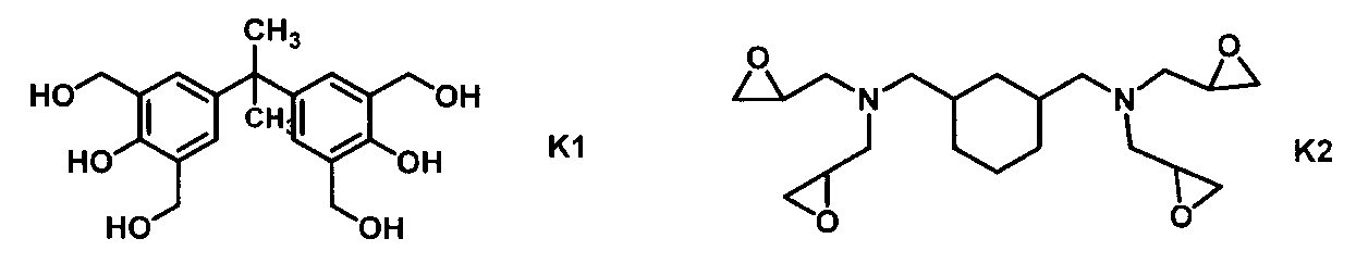
- Example 6 T2 (0.13 g), K1 (0.13 g), NEP (16.0 g) and PB were added to the polyamic acid solution (5) (10.0 g) having a resin solid content concentration of 25% by mass obtained in Synthesis Example 5.
- Example 7 T1 (0.08 g), K2 (0.08 g), NMP (23.8 g) and PB were added to the polyamic acid solution (6) (10.0 g) having a resin solid content concentration of 25% by mass obtained in Synthesis Example 6. (7.83 g) was added, and the mixture was stirred at 25 ° C. for 15 hours to obtain a liquid crystal alignment treatment agent (7).
- NMP (31.3 g) was added to the polyamic acid alkyl ester powder (8) (2.50 g) obtained in Synthesis Example 8 and dissolved by stirring at 40 ° C. for 24 hours.
- T2 (0.13 g)
- K1 (0.08 g)
- BCS (7.83 g) were added to this solution, and the mixture was stirred at 25 ° C. for 15 hours to obtain a liquid crystal alignment treatment agent (9). No abnormality such as turbidity or precipitation was observed in this liquid crystal alignment treatment agent, and it was confirmed that the solution was uniform.
- Example 10 ⁇ Example 10> T1 (0.04 g), ECS (2.48 g) and BCS (7.52 g) were added to the polysiloxane solution (1) (10.0 g) obtained in Synthesis Example 13, and the mixture was stirred at 25 ° C. for 15 hours. The liquid crystal alignment treatment agent (10) was obtained. No abnormality such as turbidity or precipitation was observed in this liquid crystal alignment treatment agent, and it was confirmed that the solution was uniform. ⁇ Example 11> T2 (0.06 g), ECS (2.48 g) and PB (7.52 g) were added to the polysiloxane solution (2) (10.0 g) obtained in Synthesis Example 14, and the mixture was stirred at 25 ° C. for 15 hours.
- the liquid crystal alignment treatment agent (11) was obtained. No abnormality such as turbidity or precipitation was observed in this liquid crystal alignment treatment agent, and it was confirmed that the solution was uniform.
- NMP (23.8 g) and BCS (7.83 g) were added to the polyamic acid solution (9) (10.0 g) having a resin solid content concentration of 25% by mass obtained in Synthesis Example 9, and the mixture was stirred at 25 ° C. for 15 hours. Then, the liquid crystal alignment treatment agent (12) was obtained. No abnormality such as turbidity or precipitation was observed in this liquid crystal alignment treatment agent, and it was confirmed that the solution was uniform.
- NMP (31.3 g) was added to the polyimide powder (10) (2.50 g) obtained in Synthesis Example 10 and stirred at 60 ° C. for 24 hours to dissolve.
- BCS (7.83 g) was added to this solution, and the mixture was stirred at 25 ° C. for 15 hours to obtain a liquid crystal alignment treatment agent (13). No abnormality such as turbidity or precipitation was observed in this liquid crystal alignment treatment agent, and it was confirmed that the solution was uniform.
- NMP (23.5 g) was added to the polyimide powder (12) (2.50 g) obtained in Synthesis Example 12, and the mixture was dissolved by stirring at 60 ° C. for 24 hours.
- * 5 A very small amount of air bubbles was observed in the element.
- * 6 Bubbles were found in the device (more than * 5).
- * 7 Many bubbles were found in the device (more than * 6).
- the examples using the liquid crystal alignment treatment agent containing the specific compound and the specific polymer are compared with the comparative example of the liquid crystal alignment treatment agent not containing them or containing only one of them.
- the liquid crystal cells were excellent in adhesion, and even if the liquid crystal cells were stored at high temperature and high humidity for a long period of time, the liquid crystal cells did not peel off.
- comparison between Example 1 and Comparative Example 1, Comparative Example 5 and Comparative Example 9, and comparison between Example 2 and Comparative Example 2, Comparative Example 6 and Comparative Example 10. A comparison between Example 3 and Comparative Example 3, Comparative Example 7 and Comparative Example 11, and a comparison between Example 4 and Comparative Example 4, Comparative Example 8 and Comparative Example 12.
- liquid crystal alignment film obtained from a liquid crystal alignment treatment agent containing a compound having a specific structure and a polymer having a specific structure, the adhesion between the substrates of the liquid crystal display element is high, and the temperature is high for a long time.
- a liquid crystal display element capable of suppressing the generation of air bubbles in the liquid crystal display element and peeling of the element can be obtained even in a harsh environment exposed to humidity. Therefore, it can be suitably used for a liquid crystal display element of a smartphone, a mobile phone, or the like.
Landscapes
- Chemical & Material Sciences (AREA)
- Physics & Mathematics (AREA)
- Nonlinear Science (AREA)
- Chemical Kinetics & Catalysis (AREA)
- Health & Medical Sciences (AREA)
- Medicinal Chemistry (AREA)
- Polymers & Plastics (AREA)
- Organic Chemistry (AREA)
- Crystallography & Structural Chemistry (AREA)
- General Physics & Mathematics (AREA)
- Optics & Photonics (AREA)
- Mathematical Physics (AREA)
- Spectroscopy & Molecular Physics (AREA)
- Liquid Crystal (AREA)
- Macromolecular Compounds Obtained By Forming Nitrogen-Containing Linkages In General (AREA)
Abstract
Description
液晶配向膜は、液晶の配向状態を制御する目的で使用されるものである。しかしながら、液晶表示素子の高精細化に伴い、液晶表示素子のコントラスト低下や長期使用に伴う表示不良の抑制が求められている。
これらに対して、ポリイミドを用いた液晶配向膜において、液晶配向性を高め、液晶表示画面周辺部に表示不良が生じにくくする手法として、アルコキシシラン化合物を添加した液晶配向処理剤を用いた液晶配向膜が提案されている(例えば特許文献1又は特許文献2参照)。
即ち、下記(A)成分及び(B)成分を含有する液晶配向処理剤である。
(B)成分:下記式[2-a]~式[2-i]から選ばれる少なくとも1種の構造(特定構造ともいう。)を有する重合体(特定重合体ともいう。)

本発明により何故に上記の優れた特性を有する液晶表示素子が得られるメカニズムは、必ずしも明らかではないが、ほぼ次のように推定される。
特定化合物は、金属との相互作用が強いリン酸基を有することから、それを含む液晶配向処理剤から得られる液晶配向膜は、ITO電極などの金属電極との密着性が高くなる。また、特定化合物の前記式[1]中のT1の構造は、紫外線や熱により、特定重合体中の特定構造と反応することができる。そのため、金属電極との密着性が高くなる特定化合物を、液晶配向膜のベースとなる特定重合体に化学結合させることができる。それにより、従来のような、金属電極との密着性を高くすることができる低分子の化合物を、液晶配向処理剤に添加する方法に比べて、液晶配向膜と金属電極との密着性を、より高くすることができると考えられる。
また、特定重合体中の特定構造は、紫外線により反応することから、液晶表示素子作製時のシール剤の硬化処理、具体的には紫外線の照射により、シール剤中の重合性化合物の反応基と反応し、液晶配向膜とシール剤との密着性が強固なものとなる。
かくして、特定化合物及び特定重合体を含有する液晶配向処理剤を用いた液晶表示素子は、液晶配向膜を形成後、液晶配向膜と金属電極、及び液晶配向膜とシール剤との密着性が高くなり、長時間、高温高湿に曝される環境においても、液晶表示素子内の気泡の発生や素子の剥がれを抑制することができる。そのため、本発明の液晶表示素子は、スマートフォンや携帯電話などの液晶表示素子に用いることができる。
特定化合物は、前記式[1]の化合物である。
式[1]中、T1、T2、Tm及びTnは、前記に定義した通りであるが、なかでもそれぞれ、下記のものが好ましい。
T1は、前記式[1-a]又は式[1-b]が好ましい。
T2は、炭素数2~12のアルキレン基が好ましく、T1とOと隣り合わない任意の-CH2-は、-O-、-COO-又は-OCO-で置換されていても良い。
Tmは、1~2の整数が好ましい。Tnは、1~2の整数が好ましい。ただし、Tm+Tnは、3である。
具体的な特定化合物としては、下記式[1a-1]~式[1a-3]の化合物が挙げられ、これらを用いることが好ましい。

特定化合物の使用割合は、液晶表示素子の液晶配向膜と電極との密着性の点から、液晶配向処理剤中のすべての重合体100質量部に対して、0.01~20質量部が好ましい。より好ましいのは、0.05~10質量部である。特に好ましいのは、0.1~10質量部である。また、特定化合物は、各特性に応じて、1種類又は2種類以上を混合して使用することもできる。
<特定構造・特定重合体>
特定構造は、前記式[2-a]~式[2-i]から選ばれる少なくとも1種の構造である。
なかでも、前記式[2-a]~式[2-c]、式[2-e]、式[2-h]又は式[2-i]が好ましい。より好ましいのは、式[2-a]、式[2-b]、式[2-h]又は式[2-i]である。特定構造を有する特定重合体としては、特に限定されないが、アクリルポリマー、メタクリルポリマー、ノボラック樹脂、ポリヒドロキシスチレン、ポリイミド前駆体、ポリイミド、ポリアミド、ポリエステル、セルロース又はポリシロキサンから選ばれる少なくとも1種の重合体が好ましい。より好ましいのは、ポリイミド前駆体、ポリイミド又はポリシロキサンである。
特定構造は、重合体を構成する繰り返し単位に含まれる形態が好ましい。特定構造を含む繰り返し単位は、重合体を構成する繰り返し単位全体に対して、10~70モル%含むことが好ましく、より好ましいのは20~60モル%含むことである。また、特定構造を有する特定重合体は、各特性に応じて、1種類又は2種類以上を混合して使用することもできる。
特定重合体にポリイミド前駆体又はポリイミド(総称してポリイミド系重合体ともいう。)を用いる場合、それらは、ジアミン成分とテトラカルボン酸成分とを反応させて得られるポリイミド前駆体又はポリイミドが好ましい。ポリイミド系重合体は、各特性に応じて、1種類又は2種類以上を混合して使用することもできる。
ジアミン成分としては、分子内に第一級又は第二級のアミノ基を2個有するジアミンであり、テトラカルボン酸成分としては、テトラカルボン酸化合物、テトラカルボン酸二無水物、テトラカルボン酸ジハライド化合物、テトラカルボン酸ジアルキルエステル化合物又はテトラカルボン酸ジアルキルエステルジハライド化合物が挙げられる。


特定構造をポリイミド系重合体に導入する方法としては、特定構造を有するジアミンを原料の一部に用いることが好ましい。特に下記式[2]の構造を有するジアミン(特定ジアミンともいう。)を用いることが好ましい。

X2は、単結合、炭素数1~18のアルキレン基、又はベンゼン環、シクロヘキサン環及び複素環から選ばれる環状基を有する炭素数6~24の有機基を示し、これら環状基上の任意の水素原子は、炭素数1~3のアルキル基、炭素数1~3のアルコキシル基、炭素数1~3のフッ素含有アルキル基、炭素数1~3のフッ素含有アルコキシル基又はフッ素原子で置換されていてもよい。なかでも、単結合、炭素数1~12のアルキレン基、ベンゼン環又はシクロヘキサン環が好ましい。より好ましいのは、単結合又は炭素数1~12のアルキレン基である。
X3は、単結合、-O-、-NH-、-N(CH3)-、-CH2O-、-CONH-、-NHCO-、-CON(CH3)-、-N(CH3)CO-、-COO-又は-OCO-を示す。なかでも、単結合、-O-、-COO-又は-OCO-が好ましい。より好ましいのは、単結合又は-OCO-である。
X4は前記式[2-a]~式[2-i]のいずれかを示す。なかでも、式[2-a]~式[2-e]、式[2-h]又は式[2-i]が好ましい。より好ましいのは、式[2-a]、式[2-b]、式[2-d]、式[2-e]又は式[2-i]である。特に好ましいのは、式[2-a]、式[2-b]又は式[2-i]である。
Xmは、1~4の整数を示す。なかでも、1又は2が好ましい。
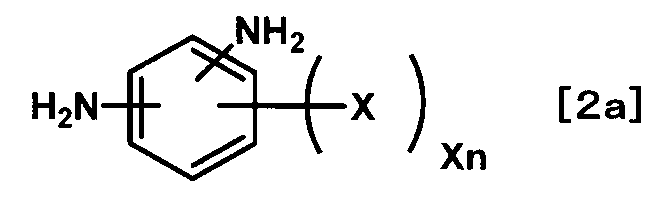
Xnは、1~4の整数を示す。なかでも、1が好ましい。
より具体的な特定ジアミンとしては、下記式[2a-1]~式[2a-12]が挙げられ、これらを用いることが好ましい。

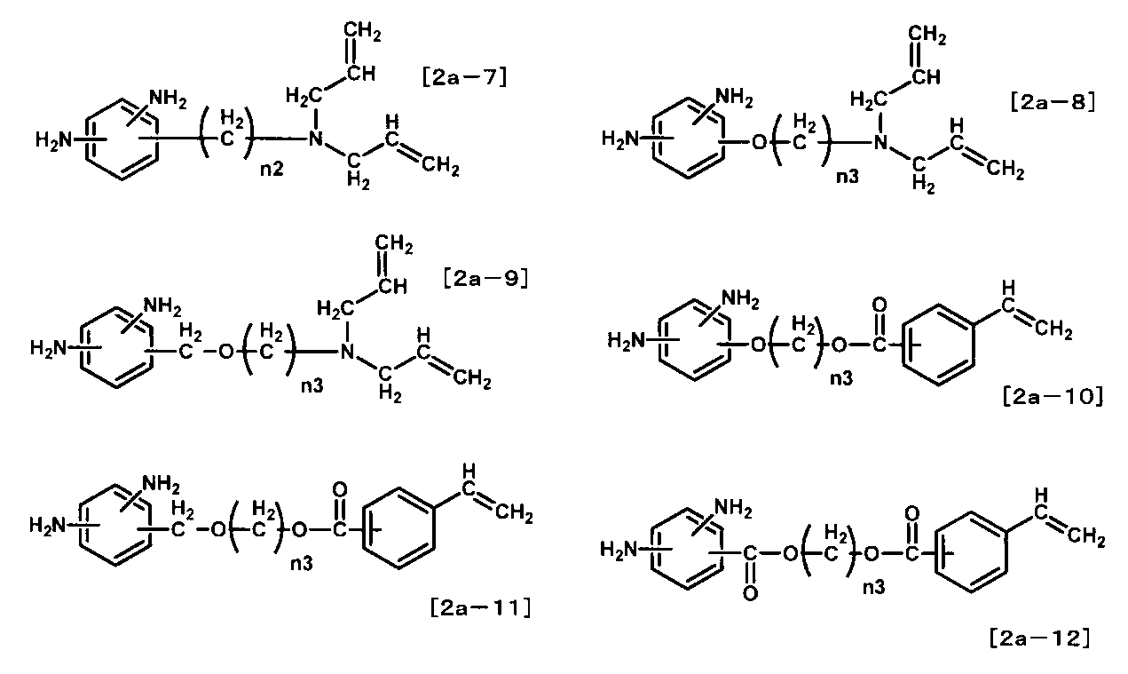
なかでも、式[2a-1]、式[2a-2]、式[2a-5]~式[2a-7]、式[2a-11]又は式[2a-12]が好ましい。より好ましいのは、式[2a-5]~式[2a-7]、式[2a-11]又は式[2a-12]である。
特定ジアミンの使用割合は、液晶表示素子の液晶配向膜とシール剤との密着性の点から、ジアミン成分全体に対し10~70モル%が好ましい。より好ましいのは、20~60モル%である。また、特定ジアミンは、各特性に応じて、1種類又は2種類以上を混合して使用できる。
ポリイミド系重合体を作製するためのテトラカルボン酸成分としては、下記式[3]のテトラカルボン酸二無水物や、そのテトラカルボン酸誘導体であるテトラカルボン酸、テトラカルボン酸ジハライド化合物、テトラカルボン酸ジアルキルエステル化合物又はテトラカルボン酸ジアルキルエステルジハライド化合物(すべてを総称して特定テトラカルボン酸成分ともいう。)を用いることが好ましい。
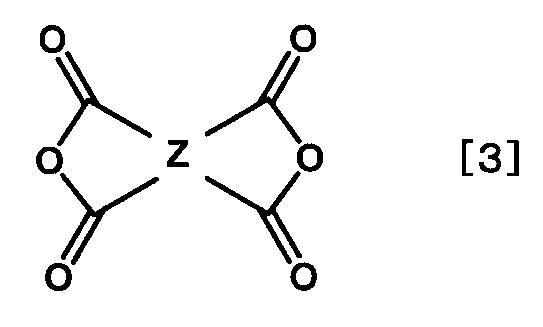
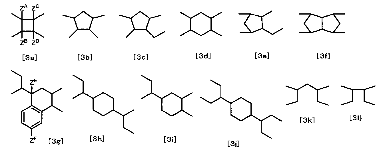
特定テトラカルボン酸成分の使用割合は、全テトラカルボン酸成分に対して1モル%以上が好ましい。より好ましいのは、5モル%以上である。特に好ましいのは、10モル%以上である。最も好ましいのは、10~90モル%である。
具体的には、国際公開公報WO2015/012368(2015.1.29公開)の34頁~35頁に記載されるその他のテトラカルボン酸成分が挙げられる。
特定テトラカルボン酸成分及びその他のテトラカルボン酸成分は、各特性に応じて、1種又は2種以上を混合して使用できる。
ポリイミド系重合体を合成する方法は、特に限定されない。通常、ジアミン成分とテトラカルボン酸成分とを反応させて得られる。具体的には、国際公開公報WO2016/076412(2016.5.19公開)の46頁~50頁に記載される方法が挙げられる。

また、これらは単独で使用しても、混合して使用してもよい。更に、ポリイミド前駆体を溶解させない溶媒であっても、生成したポリイミド前駆体が析出しない範囲で、前記の溶媒に混合して使用してもよい。また、有機溶媒中の水分は重合反応を阻害し、更には、生成したポリイミド前駆体を加水分解させる原因となるので、有機溶媒は脱水乾燥させたものを用いることが好ましい。
ポリイミド前駆体の重合反応においては、ジアミン成分の合計モル数を1.0にした際のテトラカルボン酸成分の合計モル数は、0.8~1.2であることが好ましい。
特定重合体にポリシロキサン(ポリシロキサン系重合体ともいう。)を用いる場合、下記式[A1]のアルコキシシランを重縮合させて得られるポリシロキサン、又は該式[A1]のアルコキシシランと下記式[A2]のアルコキシシランとを重縮合させて得られるポリシロキサンを用いることが好ましい。
式[A1]のアルコキシシラン:

A2は、水素原子又は炭素数1~5のアルキル基を示す。なかでも、水素原子又は炭素数1~3のアルキル基が好ましい。
A3は、炭素数1~5のアルキル基を示す。なかでも、炭素数1~3のアルキル基が好ましい。
nは、0~2の整数を示す。
pは、0~3の整数を示す。なかでも、1~3が好ましい。より好ましいのは、2又は3である。
m+n+pは、4である。
式[A1]のアルコキシシランの具体例は、下記が挙げられる。
例えば、アリルトリエトキシシラン、アリルトリメトキシシラン、ジエトキシメチルビニルシラン、ジメトキシメチルビニルシラン、トリエトキシビニルシラン、ビニルトリメトキシシラン、ビニルトリス(2-メトキシエトキシ)シラン、3-(トリエトキシシリル)プロピルメタクリレート、3-(トリメトキシシリル)プロピルアクリレート又は3-(トリメトキシシリル)プロピルメタクリレートであり、これらを用いることが好ましい。
式[A2]のアルコキシシラン:

B2は、炭素数1~5のアルキル基を示す。なかでも、炭素数1~3のアルキル基が好ましい。
nは、0~3の整数を示す。
ポリシロキサン系重合体を重縮合する方法は特に限定されない。具体的には、国際公開公報WO2015/008846(2015.1.22公開)の26頁~29頁に記載される方法が挙げられる。
本発明においては、前記方法で得られたポリシロキサン系重合体の溶液をそのまま特定重合体として用いても良いし、必要に応じて、前記の方法で得られたポリシロキサン系重合体の溶液を濃縮したり、溶媒を加えて希釈したり、他の溶媒に置換して、特定重合体として用いても良い。
ポリシロキサン系重合体は、各特性に応じて、1種類又は2種類以上を混合して使用することもできる。
<液晶配向処理剤>
液晶配向処理剤は、特定化合物及び特定重合体を含むものであり、好ましくは、液晶配向膜を形成するための溶液であり、特定化合物、特定重合体及び溶媒を含有する溶液である。その際、特定化合物及び特定重合体には、それぞれ、2種類以上のものを用いることができる。
本発明の液晶配向処理剤における重合体成分の含有量は、形成させようとする液晶配向膜の厚みの設定によって適宜変更することができるが、均一で欠陥のない液晶配向膜を形成させるという点から1重量%以上が好ましく、溶液の保存安定性の点からは10重量%以下が好ましい。なかでも、2~8重量%が好ましく、3~7重量%が特に好ましい。
また、これら溶媒B類を用いる際、液晶配向処理剤の塗布性を改善する目的に、前記溶媒A類のN-メチル-2-ピロリドン、N-エチル-2-ピロリドン又はγ-ブチロラクトンを併用して用いることが好ましい。
液晶配向処理剤には、液晶配向膜の膜強度を高めるために、エポキシ基、イソシアネート基、オキセタン基、シクロカーボネート基、ヒドロキシ基、ヒドロキシアルキル基及び低級アルコキシアルキル基から選ばれる少なくとも1種を有する化合物(総称して特定架橋性化合物ともいう。)を導入することが好ましい。その際、これらの基は、化合物中に2個以上有する必要がある。
エポキシ基又はイソシアネート基を有する架橋性化合物の具体例は、国際公開公報WO2014/171493(2014.10.23公開)の63頁~64頁に記載されるエポキシ基又はイソシアネート基を有する架橋性化合物が挙げられる。
液晶配向処理剤には、本発明の効果を損なわない限り、液晶配向処理剤を塗布した際の液晶配向膜の膜厚の均一性や表面平滑性を向上させる化合物を用いることができる。更に、液晶配向膜と基板との密着性を向上させる化合物などを用いることもできる。
液晶配向膜の膜厚の均一性や表面平滑性を向上させる化合物としては、フッ素系界面活性剤、シリコーン系界面活性剤、又はノ二オン系界面活性剤などが挙げられる。具体的には、国際公開公報WO2014/171493(2014.10.23公開)の67頁に記載される界面活性剤が挙げられる。また、その使用割合は、すべての重合体成分100質量部に対して、0.01~2質量部が好ましい。より好ましいのは、0.01~1質量部である。
<液晶配向膜・液晶表示素子>
液晶配向処理剤は、基板上に塗布、焼成した後、ラビング処理や光照射などで配向処理をして、液晶配向膜として用いることができる。また、垂直配向用途などの場合では配向処理なしでも液晶配向膜として用いることができる。
焼成後の液晶配向膜の厚みは、厚すぎると液晶表示素子の消費電力の面で不利となり、薄すぎると液晶表示素子の信頼性が低下する場合があるので、好ましくは5~300nm、より好ましくは10~200nmである。
液晶を水平配向や傾斜配向させる場合は、焼成後の液晶配向膜をラビング又は偏光紫外線照射などで処理する。
液晶表示素子に用いる液晶は、特に限定されないが、例えば、ネマチック液晶、スメクチック液晶又はコレステリック液晶を用いることができる。その際、液晶表示素子の方式に応じて、正又は負の誘電異方性を有する液晶を選択できる。また、液晶中に二色性染料を溶解させてゲストホスト型の液晶表示素子とすることもできる。
以下で用いる略語は下記の通りである。
「特定化合物」
T1:ホスマ―PE(DAP社製)
T2:KAYAMER PM-21(日本化薬社製)
「ポリイミド系重合体に用いる化合物類」
<特定ジアミン>
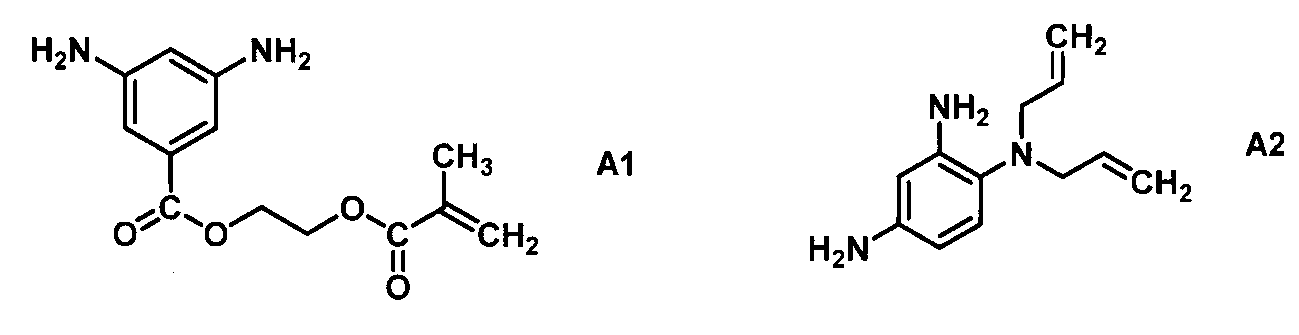


E1:3-メタクリロキシプロピルトリメトキシシラン
E2:テトラエトキシシラン

NMP:N-メチル-2-ピロリドン
NEP:N-エチル-2-ピロリドン
BCS:エチレングリコールモノブチルエーテル
PB:プロピレングリコールモノブチルエーテル
ECS:エチレングリコールモノエチルエーテル
EC:ジエチレングリコールモノエチルエーテル
「ポリイミド系重合体の分子量測定」
常温ゲル浸透クロマトグラフィー(GPC)装置(GPC-101)(昭和電工社製)、カラム(KD-803,KD-805)(Shodex社製)を用いて、以下のようにして測定した。
溶離液:N,N-ジメチルホルムアミド(添加剤として、臭化リチウム一水和物(LiBr・H2O)が30mmol/L(リットル)、リン酸・無水結晶(o-リン酸)が30mmol/L、テトラヒドロフラン(THF)が10ml/L)
流速:1.0ml/分
検量線作成用標準サンプル:TSK 標準ポリエチレンオキサイド(分子量;約900,000、150,000、100,000及び30,000)(東ソー社製)及びポリエチレングリコール(分子量;約12,000、4,000及び1,000)(ポリマーラボラトリー社製)。
「ポリイミド系重合体のイミド化率の測定」
ポリイミド粉末20mgをNMR(核磁気共鳴)サンプル管(NMRサンプリングチューブスタンダード,φ5(草野科学社製))に入れ、重水素化ジメチルスルホキシド(DMSO-d6,0.05質量%TMS(テトラメチルシラン)混合品)(0.53mL)を添加し、超音波をかけて完全に溶解させた。この溶液をNMR測定機(JNW-ECA500)(日本電子データム社製)にて500MHzのプロトンNMRを測定した。イミド化率は、イミド化前後で変化しない構造に由来するプロトンを基準プロトンとして決め、このプロトンのピーク積算値と、9.5ppm~10.0ppm付近に現れるアミド酸のNH基に由来するプロトンピーク積算値とを用い以下の式によって求めた。
(xはアミド酸のNH基由来のプロトンピーク積算値、yは基準プロトンのピーク積算値、αはポリアミド酸(イミド化率が0%)の場合におけるアミド酸のNH基プロトン1個に対する基準プロトンの個数割合である。)
「ポリイミド系重合体の合成」
<合成例1>
C2(1.12g,4.48mol)、A1(2.43g,9.19mmol)、B1(0.50g,4.62mmol)及びB2(2.63g,9.18mmol)をNMP(20.4g)中で混合し、80℃で4時間反応させた後、C1(3.50g,17.8mmol)とNMP(10.2g)を加え、40℃で6時間反応させ、樹脂固形分濃度が25質量%のポリアミド酸溶液(1)を得た。このポリアミド酸の数平均分子量(Mnともいう。)は24,200、重量平均分子量(Mwともいう。)は78,500であった。
<合成例2>
合成例1の手法で得られたポリアミド酸溶液(1)(20.0g)に、NMPを加え6質量%に希釈した後、イミド化触媒として無水酢酸(2.40g)及びピリジン(1.55g)を加え、60℃で2時間反応させた。この反応溶液をメタノール(450ml)中に投入し、得られた沈殿物を濾別した。この沈殿物をメタノールで洗浄し、100℃で減圧乾燥しポリイミド粉末(2)を得た。このポリイミドのイミド化率は62%であり、Mnは21,500、Mwは49,200であった。
<合成例3>
C2(1.87g,7.47mol)、A1(3.05g,11.5mmol)及びB3(2.93g,7.70mmol)をNMP(20.1g)中で混合し、80℃で4時間反応させた後、C1(2.20g,11.2mmol)とNMP(10.1g)を加え、40℃で6時間反応させ、樹脂固形分濃度が25質量%のポリアミド酸溶液(3)を得た。このポリアミド酸のMnは20,100、Mwは68,200であった。
<合成例4>
合成例3の手法で得られたポリアミド酸溶液(3)(20.0g)に、NMPを加え6質量%に希釈した後、イミド化触媒として無水酢酸(2.35g)及びピリジン(1.50g)を加え、60℃で1.5時間反応させた。この反応溶液をメタノール(450ml)中に投入し、得られた沈殿物を濾別した。この沈殿物をメタノールで洗浄し、100℃で減圧乾燥しポリイミド粉末(4)を得た。このポリイミドのイミド化率は55%であり、Mnは17,900、Mwは43,200であった。
<合成例5>
C2(1.11g,4.44mol)、A2(0.93g,4.57mmol)、B1(0.25g,2.31mmol)及びB3(1.73g,4.55mmol)をNEP(10.6g)中で混合し、80℃で4時間反応させた後、C1(1.30g,6.63mmol)とNEP(5.31g)を加え、40℃で6時間反応させ、樹脂固形分濃度が25質量%のポリアミド酸溶液(5)を得た。このポリアミド酸のMnは22,900、Mwは71,200であった。
<合成例6>
C3(2.30g,10.3mmol)、A1(0.56g,2.12mmol)、A2(0.43g,2.12mmol)及びB2(1.82g,6.36mmol)をNMP(15.3g)中で混合し、40℃で12時間反応させ、樹脂固形分濃度が25質量%のポリアミド酸溶液(6)を得た。このポリアミド酸のMnは20,200、Mwは54,400であった。
<合成例7>
C3(2.30g,10.3mmol)、A2(1.72g,8.46mmol)及びB4(1.04g,2.11mmol)をNMP(15.2g)中で混合し、40℃で12時間反応させ、樹脂固形分濃度が25質量%のポリアミド酸溶液(7)を得た。このポリアミド酸のMnは17,100、Mwは46,800であった。
<合成例8>
窒素雰囲気下、A1(0.51g,1.93mmol)、B1(0.31g,2.87mmol)、B2(1.39g,4.85mmol)、ピリジン(1.88g)及びNMP(15.1g)を加え、撹拌して溶解させ、C4(2.80g,9.43mmol)を加え、15℃で15時間反応させた。その後、アクリロイルクロリド(0.04g)を加え、15℃で4時間反応させた。この反応溶液を水(500g)中に投入し、得られた沈殿物を濾別した。この沈殿物をイソプロピルアルコールで洗浄し、100℃で減圧乾燥してポリアミド酸アルキルエステル粉末(8)を得た。このポリアミド酸アルキルエステルのMnは18,500、Mwは40,100であった。
<合成例9>
C2(1.31g,5.24mol)、B1(1.75g,16.2mmol)及びB2(3.08g,10.8mmol)をNMP(20.5g)中で混合し、80℃で4時間反応させた後、C1(4.10g,20.9mmol)とNMP(10.2g)を加え、40℃で6時間反応させ、樹脂固形分濃度が25質量%のポリアミド酸溶液(9)を得た。このポリアミド酸のMnは27,500、Mwは84,100であった。
<合成例10>
合成例9の手法で得られたポリアミド酸溶液(9)(20.0g)に、NMPを加え6質量%に希釈した後、イミド化触媒として無水酢酸(2.40g)及びピリジン(1.55g)を加え、60℃で2時間反応させた。この反応溶液をメタノール(450ml)中に投入し、得られた沈殿物を濾別した。この沈殿物をメタノールで洗浄し、100℃で減圧乾燥しポリイミド粉末(10)を得た。このポリイミドのイミド化率は61%であり、Mnは23,000、Mwは53,100であった。
<合成例11>
C2(2.30g,9.19mol)、B1(1.53g,14.1mmol)及びB3(3.60g,9.46mmol)をNMP(20.3g)中で混合し、80℃で4時間反応させた後、C1(2.70g,13.8mmol)とNMP(10.1g)を加え、40℃で6時間反応させ、樹脂固形分濃度が25質量%のポリアミド酸溶液(11)を得た。このポリアミド酸のMnは21,900、Mwは70,900であった。
<合成例12>
合成例11の手法で得られたポリアミド酸溶液(11)(20.0g)に、NMPを加え6質量%に希釈した後、イミド化触媒として無水酢酸(2.35g)及びピリジン(1.50g)を加え、60℃で1.5時間反応させた。この反応溶液をメタノール(450ml)中に投入し、得られた沈殿物を濾別した。この沈殿物をメタノールで洗浄し、100℃で減圧乾燥しポリイミド粉末(12)を得た。このポリイミドのイミド化率は56%であり、Mnは18,900、Mwは46,100であった。
合成例で得られたポリイミド系重合体を表1に示す。

*2:ポリアミド酸アルキルエステル。
「ポリシロキサン系重合体の合成」
<合成例13>
温度計及び還流管を備え付けた200mlの四つ口反応フラスコ中で、ECS(28.3g)、E1(7.45g)、E2(33.6g)及びE3(4.10g)を混合して、アルコキシシランモノマーの溶液を調製した。この溶液に、予め、ECS(14.2g)、水(10.8g)及び触媒として蓚酸(0.70g)を混合して調製しておいた溶液を、25℃にて30分かけて滴下し、さらに25℃にて30分間撹拌した。その後、オイルバスを用いて加熱して30分間還流させた後、放冷してSiO2換算濃度が12質量%のポリシロキサン溶液(1)を得た。
<合成例14>
温度計及び還流管を備え付けた200mlの四つ口反応フラスコ中で、EC(25.4g)、E1(19.9g)、E2(21.1g)及びE3(8.20g)を混合して、アルコキシシランモノマーの溶液を調製した。この溶液に、予め、EC(12.7g)、水(10.8g)及び触媒として蓚酸(1.10g)を混合して調製しておいた溶液を、25℃にて30分かけて滴下し、さらに25℃にて30分間撹拌した。その後、オイルバスを用いて加熱して30分間還流させた後、放冷してSiO2換算濃度が12質量%のポリシロキサン溶液(2)を得た。
合成例で得られたポリシロキサン系重合体を表2に示す。

下記する実施例1~実施例11及び比較例1~比較例12では、液晶配向処理剤の製造例を記載する。また、この液晶配向処理剤は、評価のためにも使用される。
「液晶配向処理剤の保存安定性試験」
実施例及び比較例で得られた液晶配向処理剤を用いて、保存安定性試験を行った。具体的には、液晶配向処理剤を細孔径1μmのメンブランフィルタで加圧濾過し、-15℃で72時間保管した。その後、目視観察にて、液晶配向処理剤中の濁りや析出物の発生を確認した。その結果、実施例及び比較例のすべての液晶配向処理剤は、濁りや析出物が見られず、均一な溶液であった。
「密着性の評価」
実施例及び比較例で得られた液晶配向処理剤を、純水で洗浄した100×100mmのITO電極付きPET基板(縦:100mm、横:100mm、厚さ:0.1mm)のITO面上にスピンコートにて塗布をし、ホットプレート上にて120℃で2分間加熱処理をして、膜厚が100nmの液晶配向膜付きのITO基板を得た。この液晶配向膜付きのITO基板を2枚用意し、それぞれ、100×20mm(縦×横)の大きさに切り取った。
「液晶表示素子の作製及び恒温恒湿耐性の評価」
実施例及び比較例で得られた液晶配向処理剤を、細孔径1μmのメンブランフィルタで加圧濾過し、純水及びIPAにて洗浄を行ったITO電極付き基板(縦40mm×横30mm、厚さ0.7mm)のITO面にスピンコートし、ホットプレート上にて120℃で2分間、熱循環型クリーンオーブンにて230℃で30分間加熱処理をして、膜厚が100nmの液晶配向膜付きのITO基板を得た。
<実施例1>
合成例1で得られた樹脂固形分濃度25質量%のポリアミド酸溶液(1)(10.0g)に、T1(0.13g)、NMP(23.8g)及びBCS(7.83g)を加え、25℃で15時間撹拌して、液晶配向処理剤(1)を得た。この液晶配向処理剤に、濁りや析出などの異常は見られず、均一な溶液であることが確認された。
<実施例2>
合成例2で得られたポリイミド粉末(2)(2.50g)に、NMP(31.3g)を加え、60℃で24時間撹拌して溶解させた。この溶液に、T1(0.13g)及びBCS(7.83g)を加え、25℃で15時間撹拌して、液晶配向処理剤(2)を得た。この液晶配向処理剤に、濁りや析出などの異常は見られず、均一な溶液であることが確認された。
<実施例3>
合成例3で得られた樹脂固形分濃度25質量%のポリアミド酸溶液(3)(10.0g)に、T2(0.18g)、NMP(16.0g)及びBCS(15.6g)を加え、25℃で15時間撹拌して、液晶配向処理剤(3)を得た。この液晶配向処理剤に、濁りや析出などの異常は見られず、均一な溶液であることが確認された。
<実施例4>
合成例4で得られたポリイミド粉末(4)(2.50g)に、NMP(23.5g)を加え、60℃で24時間撹拌して溶解させた。この溶液に、T2(0.18g)、BCS(3.92g)及びPB(11.8g)を加え、25℃で15時間撹拌して、液晶配向処理剤(4)を得た。この液晶配向処理剤に、濁りや析出などの異常は見られず、均一な溶液であることが確認された。
<実施例5>
合成例5で得られた樹脂固形分濃度25質量%のポリアミド酸溶液(5)(10.0g)に、T2(0.13g)、NEP(16.0g)及びPB(15.7g)を加え、25℃で15時間撹拌して、液晶配向処理剤(5)を得た。この液晶配向処理剤に、濁りや析出などの異常は見られず、均一な溶液であることが確認された。
<実施例6>
合成例5で得られた樹脂固形分濃度25質量%のポリアミド酸溶液(5)(10.0g)に、T2(0.13g)、K1(0.13g)、NEP(16.0g)及びPB(15.7g)を加え、25℃で15時間撹拌して、液晶配向処理剤(6)を得た。この液晶配向処理剤に、濁りや析出などの異常は見られず、均一な溶液であることが確認された。
<実施例7>
合成例6で得られた樹脂固形分濃度25質量%のポリアミド酸溶液(6)(10.0g)に、T1(0.08g)、K2(0.08g)、NMP(23.8g)及びPB(7.83g)を加え、25℃で15時間撹拌して、液晶配向処理剤(7)を得た。この液晶配向処理剤に、濁りや析出などの異常は見られず、均一な溶液であることが確認された。
<実施例8>
合成例7で得られた樹脂固形分濃度25質量%のポリアミド酸溶液(7)(10.0g)に、T1(0.08g)、T2(0.08g)、K2(0.18g)、NMP(19.9g)及びBCS(11.8g)を加え、25℃で15時間撹拌して、液晶配向処理剤(8)を得た。この液晶配向処理剤に、濁りや析出などの異常は見られず、均一な溶液であることが確認された。
<実施例9>
合成例8で得られたポリアミド酸アルキルエステル粉末(8)(2.50g)に、NMP(31.3g)を加え、40℃で24時間撹拌して溶解させた。この溶液に、T2(0.13g)、K1(0.08g)及びBCS(7.83g)を加え、25℃で15時間撹拌して、液晶配向処理剤(9)を得た。この液晶配向処理剤に、濁りや析出などの異常は見られず、均一な溶液であることが確認された。
<実施例10>
合成例13で得られたポリシロキサン溶液(1)(10.0g)に、T1(0.04g)、ECS(2.48g)及びBCS(7.52g)を加え、25℃で15時間撹拌して、液晶配向処理剤(10)を得た。この液晶配向処理剤に、濁りや析出などの異常は見られず、均一な溶液であることが確認された。
<実施例11>
合成例14で得られたポリシロキサン溶液(2)(10.0g)に、T2(0.06g)、ECS(2.48g)及びPB(7.52g)を加え、25℃で15時間撹拌して、液晶配向処理剤(11)を得た。この液晶配向処理剤に、濁りや析出などの異常は見られず、均一な溶液であることが確認された。
<比較例1>
合成例9で得られた樹脂固形分濃度25質量%のポリアミド酸溶液(9)(10.0g)に、NMP(23.8g)及びBCS(7.83g)を加え、25℃で15時間撹拌して、液晶配向処理剤(12)を得た。この液晶配向処理剤に、濁りや析出などの異常は見られず、均一な溶液であることが確認された。
<比較例2>
合成例10で得られたポリイミド粉末(10)(2.50g)に、NMP(31.3g)を加え、60℃で24時間撹拌して溶解させた。この溶液に、BCS(7.83g)を加え、25℃で15時間撹拌して、液晶配向処理剤(13)を得た。この液晶配向処理剤に、濁りや析出などの異常は見られず、均一な溶液であることが確認された。
<比較例3>
合成例11で得られた樹脂固形分濃度25質量%のポリアミド酸溶液(11)(10.0g)に、NMP(16.0g)及びBCS(15.6g)を加え、25℃で15時間撹拌して、液晶配向処理剤(14)を得た。この液晶配向処理剤に、濁りや析出などの異常は見られず、均一な溶液であることが確認された。
<比較例4>
合成例12で得られたポリイミド粉末(12)(2.50g)に、NMP(23.5g)を加え、60℃で24時間撹拌して溶解させた。この溶液に、BCS(3.92g)及びPB(11.8g)を加え、25℃で15時間撹拌して、液晶配向処理剤(15)を得た。この液晶配向処理剤に、濁りや析出などの異常は見られず、均一な溶液であることが確認された。
<比較例5>
合成例9で得られた樹脂固形分濃度25質量%のポリアミド酸溶液(9)(10.0g)に、T1(0.13g)、NMP(23.8g)及びBCS(7.83g)を加え、25℃で15時間撹拌して、液晶配向処理剤(16)を得た。この液晶配向処理剤に、濁りや析出などの異常は見られず、均一な溶液であることが確認された。
<比較例6>
合成例10で得られたポリイミド粉末(10)(2.50g)に、NMP(31.3g)を加え、60℃で24時間撹拌して溶解させた。この溶液に、T1(0.13g)及びBCS(7.83g)を加え、25℃で15時間撹拌して、液晶配向処理剤(17)を得た。この液晶配向処理剤に、濁りや析出などの異常は見られず、均一な溶液であることが確認された。
<比較例7>
合成例11で得られた樹脂固形分濃度25質量%のポリアミド酸溶液(11)(10.0g)に、T2(0.18g)、NMP(16.0g)及びBCS(15.6g)を加え、25℃で15時間撹拌して、液晶配向処理剤(18)を得た。この液晶配向処理剤に、濁りや析出などの異常は見られず、均一な溶液であることが確認された。
<比較例8>
合成例12で得られたポリイミド粉末(12)(2.50g)に、NMP(23.5g)を加え、60℃で24時間撹拌して溶解させた。この溶液に、T2(0.18g)、BCS(3.92g)及びPB(11.8g)を加え、25℃で15時間撹拌して、液晶配向処理剤(19)を得た。この液晶配向処理剤に、濁りや析出などの異常は見られず、均一な溶液であることが確認された。
<比較例9>
合成例1で得られた樹脂固形分濃度25質量%のポリアミド酸溶液(1)(10.0g)に、NMP(23.8g)及びBCS(7.83g)を加え、25℃で15時間撹拌して、液晶配向処理剤(20)を得た。この液晶配向処理剤に、濁りや析出などの異常は見られず、均一な溶液であることが確認された。
<比較例10>
合成例2で得られたポリイミド粉末(2)(2.50g)に、NMP(31.3g)を加え、60℃で24時間撹拌して溶解させた。この溶液に、BCS(7.83g)を加え、25℃で15時間撹拌して、液晶配向処理剤(21)を得た。この液晶配向処理剤に、濁りや析出などの異常は見られず、均一な溶液であることが確認された。
<比較例11>
合成例3で得られた樹脂固形分濃度25質量%のポリアミド酸溶液(3)(10.0g)に、NMP(16.0g)及びBCS(15.6g)を加え、25℃で15時間撹拌して、液晶配向処理剤(22)を得た。この液晶配向処理剤に、濁りや析出などの異常は見られず、均一な溶液であることが確認された。
<比較例12>
合成例4で得られたポリイミド粉末(4)(2.50g)に、NMP(23.5g)を加え、60℃で24時間撹拌して溶解させた。この溶液に、BCS(3.92g)及びPB(11.8g)を加え、25℃で15時間撹拌して、液晶配向処理剤(23)を得た。この液晶配向処理剤に、濁りや析出などの異常は見られず、均一な溶液であることが確認された。
<実施例1~実施例11及び比較例1~比較例12>
前記液晶配向処理剤(1)~(23)を用いて、前記条件で、「密着性の評価」及び「液晶表示素子の作製及び恒温恒湿耐性の評価」を行った。


*4:括弧内の数値は重合体100質量部に対する架橋性化合物の導入量(質量部)を示す。


*6:素子内に気泡が見られた(*5よりも多い)。
*7:素子内に多くの気泡が見られた(*6よりも多い)。
さらに、液晶配向処理剤の保存安定性試験では、すべての実施例において、濁りや析出物が見られず、均一な溶液であった。
Claims (15)
- 下記(A)成分及び(B)成分を含有する液晶配向処理剤。
(A)成分:下記式[1]の化合物
(B)成分:下記式[2-a]~式[2-i]から選ばれる少なくとも1種の構造を有する重合体


- 前記式[1]の化合物が、下記式[1a-1]~式[1a-3]のいずれかである請求項1に記載の液晶配向処理剤。
- 前記重合体が、アクリルポリマー、メタクリルポリマー、ノボラック樹脂、ポリヒドロキシスチレン、ポリイミド前駆体、ポリイミド、ポリアミド、ポリエステル、セルロース及びポリシロキサンから選ばれる少なくとも1種である請求項1又は請求項2に記載の液晶配向処理剤。
- 前記重合体が、前記式[2-a]~式[2-i]から選ばれる少なくとも1種の構造を有するジアミンを原料の一部に用いて得られるポリイミド前駆体又はポリイミドを含む請求項3に記載の液晶配向処理剤。
- 前記ジアミンが、下記式[2]の構造を有する請求項4に記載の液晶配向処理剤。

- 前記ジアミンが、下記式[2a]である請求項5に記載の液晶配向処理剤。

- 前記ジアミンが、下記式[2a-1]~式[2a-12]から選ばれる少なくとも1種である、請求項4~請求項6のいずれか一項に記載の液晶配向処理剤。

- 前記重合体が、下記式[3]のテトラカルボン酸成分を原料の一部に用いて得られるポリイミド前駆体又はポリイミドである請求項4~請求項7のいずれか一項に記載の液晶配向処理剤。

- 前記重合体が、下記式[A1]のアルコキシシランを重縮合させて得られるポリシロキサン、又は該式[A1]のアルコキシシランと下記式[A2]のアルコキシシランとを重縮合させて得られるポリシロキサンを含む請求項3に記載の液晶配向処理剤。


- 前記式[A1]のアルコキシシランが、アリルトリエトキシシラン、アリルトリメトキシシラン、ジエトキシメチルビニルシラン、ジメトキシメチルビニルシラン、トリエトキシビニルシラン、ビニルトリメトキシシラン、ビニルトリス(2-メトキシエトキシ)シラン、3-(トリエトキシシリル)プロピルメタクリレート、3-(トリメトキシシリル)プロピルアクリレート、及び3-(トリメトキシシリル)プロピルメタクリレートから選ばれる少なくとも1種であり、
前記式[A2]のアルコキシシランが、テトラメトキシシラン、テトラエトキシシラン、テトラプロポキシシラン、及びテトラブトキシシランから選ばれる少なくとも1種である、請求項9に記載の液晶配向処理剤。 - 前記液晶配向処理剤が、エポキシ基、イソシアネート基、オキセタン基、シクロカーボネート基、ヒドロキシ基、ヒドロキシアルキル基及び低級アルコキシアルキル基から選ばれる少なくとも1種を有する架橋性化合物をさらに含む、請求項1~請求項10のいずれか一項に記載の液晶配向処理剤。
- 前記式[1]の化合物の使用割合が、液晶配向処理剤中のすべての重合体100質量部に対して、0.01~20質量部である、請求項1~請求項11のいずれか一項に記載の液晶配向処理剤。
- 前記重合体が、前記式[2-a]~式[2-i]から選ばれる少なくとも1種の構造を有する繰り返し単位を有し、該繰り返し単位が重合体を構成する繰り返し単位全体に対して10~70モル%含まれる、請求項1~12のいずれか一項に記載の液晶配向処理剤。
- 請求項1~請求項13のいずれか一項に記載の液晶配向処理剤から得られる液晶配向膜。
- 請求項14に記載の液晶配向膜を有する液晶表示素子。
Priority Applications (3)
| Application Number | Priority Date | Filing Date | Title |
|---|---|---|---|
| KR1020217031182A KR102860168B1 (ko) | 2019-03-08 | 2020-03-06 | 액정 배향 처리제, 액정 배향막 및 액정 표시 소자 |
| JP2021505018A JP7424366B2 (ja) | 2019-03-08 | 2020-03-06 | 液晶配向処理剤、液晶配向膜及び液晶表示素子 |
| CN202080016064.4A CN113474724B (zh) | 2019-03-08 | 2020-03-06 | 液晶取向处理剂、液晶取向膜以及液晶显示元件 |
Applications Claiming Priority (2)
| Application Number | Priority Date | Filing Date | Title |
|---|---|---|---|
| JP2019-042709 | 2019-03-08 | ||
| JP2019042709 | 2019-03-08 |
Publications (1)
| Publication Number | Publication Date |
|---|---|
| WO2020184424A1 true WO2020184424A1 (ja) | 2020-09-17 |
Family
ID=72427824
Family Applications (1)
| Application Number | Title | Priority Date | Filing Date |
|---|---|---|---|
| PCT/JP2020/009632 Ceased WO2020184424A1 (ja) | 2019-03-08 | 2020-03-06 | 液晶配向処理剤、液晶配向膜及び液晶表示素子 |
Country Status (5)
| Country | Link |
|---|---|
| JP (1) | JP7424366B2 (ja) |
| KR (1) | KR102860168B1 (ja) |
| CN (1) | CN113474724B (ja) |
| TW (1) | TWI839481B (ja) |
| WO (1) | WO2020184424A1 (ja) |
Cited By (2)
| Publication number | Priority date | Publication date | Assignee | Title |
|---|---|---|---|---|
| JP2022154781A (ja) * | 2021-03-30 | 2022-10-13 | 株式会社ジャパンディスプレイ | 配向膜材料、及び、液晶表示装置 |
| WO2026053874A1 (ja) * | 2024-09-03 | 2026-03-12 | 日産化学株式会社 | フレキシブルデバイス基板形成用組成物 |
Citations (3)
| Publication number | Priority date | Publication date | Assignee | Title |
|---|---|---|---|---|
| WO2007139207A1 (ja) * | 2006-05-26 | 2007-12-06 | Tokuyama Dental Corporation | 1液型歯科用接着性組成物 |
| JP2016069486A (ja) * | 2014-09-29 | 2016-05-09 | 富士フイルム株式会社 | 液晶組成物、偏光発光フィルム、波長変換部材およびその製造方法、バックライトユニット、液晶表示装置 |
| JP2018203945A (ja) * | 2017-06-08 | 2018-12-27 | Dic株式会社 | 重合性液晶組成物、及び、それを用いた光学異方体 |
Family Cites Families (8)
| Publication number | Priority date | Publication date | Assignee | Title |
|---|---|---|---|---|
| JPS61171762A (ja) | 1985-01-28 | 1986-08-02 | Japan Synthetic Rubber Co Ltd | 可溶性ポリイミド樹脂組成物 |
| JP2980080B2 (ja) | 1997-10-09 | 1999-11-22 | ジェイエスアール株式会社 | 液晶配向剤 |
| KR101010036B1 (ko) * | 2009-08-28 | 2011-01-21 | 주식회사 엘지화학 | 신규한 폴리아믹산, 이를 포함하는 감광성 수지 조성물 및 이로부터 제조된 드라이 필름 |
| TWI564339B (zh) * | 2010-06-30 | 2017-01-01 | Nissan Chemical Ind Ltd | A polymerizable compound, a liquid crystal alignment agent, a liquid crystal alignment film, and a liquid crystal display device, and a method of manufacturing the liquid crystal display device |
| KR102411032B1 (ko) * | 2014-06-17 | 2022-06-17 | 닛산 가가쿠 가부시키가이샤 | 액정 표시 소자, 액정 배향막, 및 액정 배향 처리제 |
| EP3163367B1 (en) * | 2014-06-25 | 2019-03-06 | Nissan Chemical Corporation | Liquid crystal display element |
| EP3200022B1 (en) * | 2014-09-25 | 2019-06-26 | Nissan Chemical Corporation | Liquid crystal display device |
| JP6686889B2 (ja) * | 2014-09-25 | 2020-04-22 | 日産化学株式会社 | 液晶表示素子 |
-
2020
- 2020-03-06 WO PCT/JP2020/009632 patent/WO2020184424A1/ja not_active Ceased
- 2020-03-06 CN CN202080016064.4A patent/CN113474724B/zh active Active
- 2020-03-06 TW TW109107408A patent/TWI839481B/zh active
- 2020-03-06 JP JP2021505018A patent/JP7424366B2/ja active Active
- 2020-03-06 KR KR1020217031182A patent/KR102860168B1/ko active Active
Patent Citations (3)
| Publication number | Priority date | Publication date | Assignee | Title |
|---|---|---|---|---|
| WO2007139207A1 (ja) * | 2006-05-26 | 2007-12-06 | Tokuyama Dental Corporation | 1液型歯科用接着性組成物 |
| JP2016069486A (ja) * | 2014-09-29 | 2016-05-09 | 富士フイルム株式会社 | 液晶組成物、偏光発光フィルム、波長変換部材およびその製造方法、バックライトユニット、液晶表示装置 |
| JP2018203945A (ja) * | 2017-06-08 | 2018-12-27 | Dic株式会社 | 重合性液晶組成物、及び、それを用いた光学異方体 |
Cited By (3)
| Publication number | Priority date | Publication date | Assignee | Title |
|---|---|---|---|---|
| JP2022154781A (ja) * | 2021-03-30 | 2022-10-13 | 株式会社ジャパンディスプレイ | 配向膜材料、及び、液晶表示装置 |
| JP7652607B2 (ja) | 2021-03-30 | 2025-03-27 | 株式会社ジャパンディスプレイ | 配向膜材料、及び、液晶表示装置 |
| WO2026053874A1 (ja) * | 2024-09-03 | 2026-03-12 | 日産化学株式会社 | フレキシブルデバイス基板形成用組成物 |
Also Published As
| Publication number | Publication date |
|---|---|
| JP7424366B2 (ja) | 2024-01-30 |
| TWI839481B (zh) | 2024-04-21 |
| CN113474724B (zh) | 2024-12-17 |
| KR102860168B1 (ko) | 2025-09-15 |
| CN113474724A (zh) | 2021-10-01 |
| KR20210138031A (ko) | 2021-11-18 |
| JPWO2020184424A1 (ja) | 2020-09-17 |
| TW202104436A (zh) | 2021-02-01 |
Similar Documents
| Publication | Publication Date | Title |
|---|---|---|
| JP6418317B2 (ja) | 液晶表示素子 | |
| KR102811814B1 (ko) | 수지 조성물, 수지막 및 액정 표시 소자 | |
| TWI801402B (zh) | 樹脂組成物、樹脂膜及液晶顯示元件 | |
| JP6409149B2 (ja) | 液晶表示素子 | |
| KR102596591B1 (ko) | 화합물, 액정 조성물 및 액정 표시 소자 | |
| JP6406472B2 (ja) | 液晶表示素子 | |
| JP7424366B2 (ja) | 液晶配向処理剤、液晶配向膜及び液晶表示素子 | |
| JPWO2020138112A1 (ja) | 液晶配向処理剤、液晶配向膜及び液晶表示素子 | |
| JP7226429B2 (ja) | 液晶表示素子 | |
| JP7424364B2 (ja) | 液晶配向処理剤、液晶配向膜及び液晶表示素子 | |
| CN113260910B (zh) | 液晶取向处理剂、液晶取向膜以及液晶显示元件 | |
| JP7424363B2 (ja) | 樹脂組成物、樹脂膜及び液晶表示素子 | |
| WO2020175518A1 (ja) | 液晶表示素子及びその製造方法 |
Legal Events
| Date | Code | Title | Description |
|---|---|---|---|
| 121 | Ep: the epo has been informed by wipo that ep was designated in this application |
Ref document number: 20769431 Country of ref document: EP Kind code of ref document: A1 |
|
| ENP | Entry into the national phase |
Ref document number: 2021505018 Country of ref document: JP Kind code of ref document: A |
|
| NENP | Non-entry into the national phase |
Ref country code: DE |
|
| ENP | Entry into the national phase |
Ref document number: 20217031182 Country of ref document: KR Kind code of ref document: A |
|
| 122 | Ep: pct application non-entry in european phase |
Ref document number: 20769431 Country of ref document: EP Kind code of ref document: A1 |