WO2020184411A1 - 模様付製品成形用押出しダイス - Google Patents
模様付製品成形用押出しダイス Download PDFInfo
- Publication number
- WO2020184411A1 WO2020184411A1 PCT/JP2020/009576 JP2020009576W WO2020184411A1 WO 2020184411 A1 WO2020184411 A1 WO 2020184411A1 JP 2020009576 W JP2020009576 W JP 2020009576W WO 2020184411 A1 WO2020184411 A1 WO 2020184411A1
- Authority
- WO
- WIPO (PCT)
- Prior art keywords
- die
- gear
- product
- molding
- flat plate
- Prior art date
- Legal status (The legal status is an assumption and is not a legal conclusion. Google has not performed a legal analysis and makes no representation as to the accuracy of the status listed.)
- Ceased
Links
Images







Classifications
-
- B—PERFORMING OPERATIONS; TRANSPORTING
- B21—MECHANICAL METAL-WORKING WITHOUT ESSENTIALLY REMOVING MATERIAL; PUNCHING METAL
- B21C—MANUFACTURE OF METAL SHEETS, WIRE, RODS, TUBES, PROFILES OR LIKE SEMI-MANUFACTURED PRODUCTS OTHERWISE THAN BY ROLLING; AUXILIARY OPERATIONS USED IN CONNECTION WITH METAL-WORKING WITHOUT ESSENTIALLY REMOVING MATERIAL
- B21C23/00—Extruding metal; Impact extrusion
- B21C23/02—Making uncoated products
- B21C23/04—Making uncoated products by direct extrusion
- B21C23/14—Making other products
-
- B—PERFORMING OPERATIONS; TRANSPORTING
- B21—MECHANICAL METAL-WORKING WITHOUT ESSENTIALLY REMOVING MATERIAL; PUNCHING METAL
- B21C—MANUFACTURE OF METAL SHEETS, WIRE, RODS, TUBES, PROFILES OR LIKE SEMI-MANUFACTURED PRODUCTS OTHERWISE THAN BY ROLLING; AUXILIARY OPERATIONS USED IN CONNECTION WITH METAL-WORKING WITHOUT ESSENTIALLY REMOVING MATERIAL
- B21C25/00—Profiling tools for metal extruding
- B21C25/02—Dies
-
- B—PERFORMING OPERATIONS; TRANSPORTING
- B21—MECHANICAL METAL-WORKING WITHOUT ESSENTIALLY REMOVING MATERIAL; PUNCHING METAL
- B21C—MANUFACTURE OF METAL SHEETS, WIRE, RODS, TUBES, PROFILES OR LIKE SEMI-MANUFACTURED PRODUCTS OTHERWISE THAN BY ROLLING; AUXILIARY OPERATIONS USED IN CONNECTION WITH METAL-WORKING WITHOUT ESSENTIALLY REMOVING MATERIAL
- B21C25/00—Profiling tools for metal extruding
- B21C25/08—Dies or mandrels with section variable during extruding, e.g. for making tapered work; Controlling variation
-
- B—PERFORMING OPERATIONS; TRANSPORTING
- B29—WORKING OF PLASTICS; WORKING OF SUBSTANCES IN A PLASTIC STATE IN GENERAL
- B29C—SHAPING OR JOINING OF PLASTICS; SHAPING OF MATERIAL IN A PLASTIC STATE, NOT OTHERWISE PROVIDED FOR; AFTER-TREATMENT OF THE SHAPED PRODUCTS, e.g. REPAIRING
- B29C48/00—Extrusion moulding, i.e. expressing the moulding material through a die or nozzle which imparts the desired form; Apparatus therefor
- B29C48/03—Extrusion moulding, i.e. expressing the moulding material through a die or nozzle which imparts the desired form; Apparatus therefor characterised by the shape of the extruded material at extrusion
- B29C48/13—Articles with a cross-section varying in the longitudinal direction, e.g. corrugated pipes
-
- B—PERFORMING OPERATIONS; TRANSPORTING
- B29—WORKING OF PLASTICS; WORKING OF SUBSTANCES IN A PLASTIC STATE IN GENERAL
- B29C—SHAPING OR JOINING OF PLASTICS; SHAPING OF MATERIAL IN A PLASTIC STATE, NOT OTHERWISE PROVIDED FOR; AFTER-TREATMENT OF THE SHAPED PRODUCTS, e.g. REPAIRING
- B29C48/00—Extrusion moulding, i.e. expressing the moulding material through a die or nozzle which imparts the desired form; Apparatus therefor
- B29C48/25—Component parts, details or accessories; Auxiliary operations
- B29C48/30—Extrusion nozzles or dies
- B29C48/35—Extrusion nozzles or dies with rollers
-
- B—PERFORMING OPERATIONS; TRANSPORTING
- B29—WORKING OF PLASTICS; WORKING OF SUBSTANCES IN A PLASTIC STATE IN GENERAL
- B29C—SHAPING OR JOINING OF PLASTICS; SHAPING OF MATERIAL IN A PLASTIC STATE, NOT OTHERWISE PROVIDED FOR; AFTER-TREATMENT OF THE SHAPED PRODUCTS, e.g. REPAIRING
- B29C48/00—Extrusion moulding, i.e. expressing the moulding material through a die or nozzle which imparts the desired form; Apparatus therefor
- B29C48/25—Component parts, details or accessories; Auxiliary operations
- B29C48/88—Thermal treatment of the stream of extruded material, e.g. cooling
- B29C48/90—Thermal treatment of the stream of extruded material, e.g. cooling with calibration or sizing, i.e. combined with fixing or setting of the final dimensions of the extruded article
Definitions
- the present invention relates to an extruded die for molding a patterned product as a thermoplastic material, for example, by molding a predetermined pattern on the surface of a product member formed of an alumnium alloy to manufacture a patterned product.
- aluminum alloys and the like are suitable for extrusion processing because they can obtain various shapes such as high thermal conductivity, excellent workability, and high degree of freedom in cross-sectional shape. Therefore, this extrusion process is now widely used. For example, by extruding an aluminum alloy, a flat multi-hole pipe having a large number of holes continuous in the width direction, a long flat plate, a pipe member, etc. are formed, or the surface has irregularities such as a rack shape or a wavy shape. The pattern of the shape is also formed.
- Patent Document 1 As a technique for forming a pattern on the surface of a long material, a plastically deformable metal stamping apparatus and method are known (see, for example, Patent Document 1).
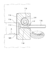
- a recess 129 for introducing a metal for introducing a plastically deformable metal 115 and a subsequent opening 111 are formed in the fixed die 110.
- a support surface 118 that guides the flow of the metal 115 is formed.
- a gear 119 for forming a rack is arranged on one surface of the metal 115 extruded along the support surface 118. As shown by the arrow A, the gear 119 rotates with the extruded metal 115 to form a rack on the surface of the metal 115.
- the support surface 118 is generally a portion corresponding to a bearing portion that determines the shape of the metal 115 as a product.
- the downstream end of the support surface 118 in Patent Document 1 has a length to a position substantially opposite to the top of the gear, and the downstream end of the support surface 118 is short.
- the downstream end of the support surface 118 is a terminal portion, and a relief portion extending outward is continuously formed at the terminal portion.
- the downstream end of the metal 115 on the support surface 118 in the flow direction is the end of the support surface 118, and the end is a gear with the metal 115 in between. It is positioned to face the top of the 119 tooth. Therefore, at the end of the support surface 118, the pressing force of the gear 119 when forming the rack pattern is applied to the surface of the metal 115, but at that time, the back surface of the metal 115 is in close contact with the support surface 118, so that the back surface is on the back surface. No uneven pattern is generated.
- the length of the support surface 118 is short, the portion facing the top of the gear is a substantially terminal portion of the support surface 118, and an opening that greatly extends outward is formed from the portion.
- the metal 115 is continuously extruded at a constant speed. Therefore, when the metal 115 pushed toward the support surface 118 by the gear 119 passes through the end of the support surface 118, as shown in the enlarged portion, there is no portion that supports the back surface of the metal 115, so that the metal 115 spreads outward. There is a problem that the metal 115 is pushed by the large opening and the pressing force of the gear 119 is displaced as if it were pushed, and the metal 115 appears as an uneven portion on the back surface side.
- the product is originally required to have a rack-like pattern only on the front surface side of the metal 115, an uneven portion is generated on the back surface side, resulting in a defective product. It ends up. As a result, the defective product is disposed of, resulting in waste of materials and working time, and there is also a problem that productivity is lowered.
- the present invention when a pattern is formed on the front surface of a product member formed of a thermoplastic material, it is possible to prevent the occurrence of unevenness on the back surface of the product member. It is an object of the present invention to provide an extruded die for molding a patterned product, which can improve productivity.
- the extruded die for molding a patterned product of the present invention is a molded product with a pattern that forms a pattern on the surface of a product member formed of a thermoplastic member continuously extruded from the material supply side.
- Extruded die for An upper die for introducing the thermoplastic member and a lower die for supporting the upper die are provided, and the upper die molds the thermoplastic member into the shape of the product member.
- the lower die has a bearing portion, and the lower die has a lower guide portion for the product member that guides the movement of the product member formed by the bearing portion, and the pattern is formed on one surface of the product member.
- a pattern forming tool is provided, and the lower guide portion for the product member is characterized in that a relief portion for absorbing the pressing force during pattern forming by the pattern forming tool is formed.
- the extruded die for molding a patterned product of the present invention is configured as described above, and the product member extruded in a state of being molded by the bearing portion of the upper die is the lower guide for the product member of the lower die.
- a pattern is formed on the surface of the product member by the pattern forming tool while moving along the portion. At this time, the pattern forming tool presses the surface of the product member, but a relief portion is formed in the lower guide portion for the product member, and the pressing force applied to the product member is absorbed by the relief portion. , The product member is pressed against the lower guide portion for the product member.
- FIG. 6 is a plan sectional view taken along the line VII-VII in FIG. 6 is a plan sectional view taken along the line VIII-VIII in FIG. It is a perspective view of the vertical cross section along the IX-IX line in FIG. It is a perspective view which shows the state which took out a gear, a gear attachment member, and a gear position adjustment mechanism from the state of FIG. It is a perspective view which shows the state which the upper block member was removed from the state of FIG.
- the gear position adjusting mechanism of the first embodiment is shown, and FIG. 3A shows a state in which the gear bites into the flat plate as much as possible, and FIG. 3A shows a state in which the gear bites into the flat plate slightly. It is a plan view.
- the extruded die 1 of the present embodiment uses a metal M made of an aluminum alloy, which is a thermoplastic material that is continuously extruded with a substantially clay-like softness, and is, for example, a patterned product as shown in FIG. It is used to form a flat plate 40.
- the flat plate 40 is formed in a long shape with a predetermined thickness, and a rack-shaped pattern D is formed on one surface thereof.
- the flat plate 40 is used as a floor plate having excellent design by arranging a large number of flat plates 40 in succession, and is also used as a non-slip member.
- the extrusion die 1 supports the upper die 10 into which the metal M extruded and supplied from the metal supply device 100 on the material supply side is introduced, and the upper die 10 and supports the upper die 10.
- a lower die 20 for forming the metal M into a predetermined product member shape is provided.
- the lower die 20 is equipped with a gear 30 which is a pattern forming tool for forming a rack-shaped pattern on one surface (surface) of the product member.
- the upper die 10 and the lower die 20 are each formed of substantially cylindrical members, and the upper die 10 is formed to have a smaller diameter than the lower die 20.
- the upper die 10 and the lower die 20 are connected by, for example, a connecting bolt (not shown) inserted from the back surface of the lower die 20.
- the metal M is housed in the metal supply device 100 including a chamber and the like arranged on the upstream side of the upper die 10, and is extruded by the metal supply device 100. It has become so. Then, the metal M is made into, for example, clay-like softness in the metal supply device 100, and the state is maintained. Further, the metal supply device 100 holds the upper die 10.
- the configuration of the upper die 10 will be described. As shown in FIGS. 5 and 6, the upper die 10 is continuously connected to the first metal introduction port 10A for guiding the introduction of the metal M extruded from the metal extrusion device 100 and the first metal introduction port 10A. Further, a second metal introduction port 10B having an opening narrowed from the first metal introduction port 10A is formed.
- a bearing portion 10C that is continuous with the second metal introduction port 10B and has an opening narrowed from the second metal introduction port 10B is formed downstream of the second metal introduction port 10B.
- the bearing portion 10C is a portion where the metal M is formed into the shape of a flat plate 40 which is a member for products. Specifically, as shown in FIG. 7, the extruded metal M is formed into a vertical dimension H1 having a rectangular cross section and a horizontal dimension W1 to form the flat plate 40.
- an upper flat plate guide portion 10D that is continuous with the bearing portion 10C and has a wider opening than the bearing portion 10C is formed below the bearing portion 10C.
- the upper flat plate guide portion 10D is a portion that guides the metal M formed and extruded by the bearing portion 10C to the lower die 20 side.
- the cross-sectional shape of the extruded metal M that is, the vertical dimension H1 of the bearing portion 10C and the vertical dimension H2 larger than the horizontal dimension W1 by the dimensions S1 and S, respectively, and the horizontal dimension. It is a through hole having a rectangular cross section made of W2.
- the dimensions S1 and S are substantially the same.
- the lower die 20 is formed of a substantially columnar member, and a shallow circular recess 20A is formed on the upper surface thereof for positioning when the upper die 10 is placed.
- the lower die 20 is formed with a gear arrangement space 20B for arranging the gear 30 in the vicinity of a substantially central portion of the plane thereof, and the gear arrangement space 20B is a through hole having a substantially rectangular shape. .. Further, on both sides of the gear arrangement space 20B along the length direction, holes 20C for installing the gear mounting member 32, which will be described later, are formed.
- the gear mounting member installation hole 20C is provided along the longitudinal direction of the gear arrangement space 20B, has an elongated shape having a predetermined width and a total length of dimension L, and is formed to a predetermined depth.
- the gear mounting member 32 is inserted into the gear mounting member installation hole 20C, and the gear mounting member 32 includes a pair of upper and lower mounting blocks 32A as shown in FIG. 10 and the like. It is composed of a lower mounting block 32B.
- a flat wall portion 20D is formed on a part of the outer periphery of the lower die 20 at a position on the extension of each gear mounting member installation hole 20C. These flat wall portions 20D are parallel to the surface of the end portion in the length direction of the gear mounting member installation hole 20C. Then, a screw hole 20E is cut between these flat wall portions 20D and one side surface portion of the gear mounting member installation hole 20C, and the screw hole 20E is used for position adjustment to form a gear position adjusting mechanism described later. Bolts 35 (see FIG. 4 and the like) are screwed together. As shown in FIGS. 12 and 13, the screw holes 20E correspond to the upper mounting block 32A and the lower mounting block 32B, respectively.
- FIG. 4 shows a state in which the gear 30 and the gear mounting member 32 are arranged in the gear arrangement space 20B of the lower die 20 and the gear mounting member installation hole 20C, respectively.
- the gear 30 is arranged to the left of the gear arrangement space 20B, and a space SP having a predetermined size is provided on the right side of the gear 30, and a portion of this space SP. Is the insertion portion P of the extruded metal M (see also FIG. 8).
- the lower die 20 is formed with a lower flat plate guide portion 20F that guides the flat plate 40 formed by the bearing portion 10C.
- the lower flat plate guide portion 20F is formed from the upper end surface to the lower end surface.
- the lower flat plate guide portion 20F is formed in a U-shaped cross section as shown in FIG. 8, and the size of the U-shaped cross section is the same as that of the upper flat plate guide portion 10D of the upper die 10. ..
- the upper flat plate guide portion 10D is formed to have the same shape as the one surface on the gear 30 side is removed. That is, the vertical dimension is H2 and the horizontal dimension is W3.
- the gear 30 for forming a pattern D on the surface 40A of the flat plate 40 is arranged in a region opposite to the lower flat plate guide portion 20F with the flat plate 40 of the lower die 20 in between.
- the pattern D is formed by a concave portion 40a and a convex portion 40b formed on the surface 40A of the flat plate 40, and the concave portion 40a and the convex portion 40b are the tooth top portion 30a and the valley portion 30b of the gear 30.
- the top portion 30a and the valley portion 30b are formed.
- the gap S having a predetermined dimension is provided between one surface of the flat plate 40 facing the back surface 40B and the back surface 40B of the flat plate 40, and the gear 30 is a flat plate in this gap S.
- the rack-shaped pattern D is formed on the surface of the 40
- the relief portion E for releasing the pressing force by the top portion 30a of the gear 30 is formed. Therefore, when the gear 30 forms a rack-shaped pattern D on the surface of the flat plate 40 by the top 30a, when the top 30a of the gear 30 presses the flat plate 40, the pressing force of the gear 30 is absorbed by the relief portion E, that is, , The flat plate 40 is pushed and pressed against the lower flat plate guide portion 20F. As a result, since the back surface 40B of the flat plate 40 and one surface of the lower flat plate guide portion 20F are in close contact with each other, unevenness generated on the back surface 40B of the flat plate 40 can be prevented.
- the flat plate 40 via the bearing portion 10C and the upper flat plate guide portion 10D of the upper die 10 has a rack shape by the gear 30 while being guided along the lower flat plate guide portion 20F of the lower die 20.
- Pattern D is formed.
- the gear 30 is arranged at a position facing the lower flat plate guide portion 20F with the flat plate 40 in between. Further, as shown in FIGS. 9 and 10, the gear 30 is provided with its shaft portion 30A sandwiched between a pair of upper and lower mounting blocks 32A and 32B constituting the mounting member 32. As shown in FIG. 12 and the like, the mounting member 32 is inserted into the gear mounting member installation hole 20C and is slidably fitted to the flat plate 40 side. The gear 30 and the shaft portion 30A are connected by a key 39 (see FIG. 6 and the like).
- the pair of upper and lower mounting blocks 32A and 32B are connected by a connecting bolt 34 inserted from the upper mounting block 32A.
- a high-temperature bearing 36 is fitted to the shaft portion 30A of the gear 30, and the high-temperature bearing 36 is fitted into the recesses 32Aa and 32Ba at the center of each of the mounting blocks 32A and 32B in the length direction. There is.
- the gear position adjusting mechanism 38 is detachably provided in the gear position adjusting bolts 35 and 35 that come into contact with one end of the upper and lower mounting blocks 32A and 32B in the length direction and the gear mounting member installation hole 20C. It is composed of an adjustment washer 37.
- the gear position adjusting bolts 35 and 35 are formed in screw holes 20E formed from the flat wall portion 20D formed on the outer peripheral side surface of the lower die 20 toward the respective side surfaces of the pair of upper and lower mounting blocks 32A and 32B. By screwing, the tips of the bolts 35 and 35 are brought into contact with the one-sided ends of the mounting blocks 32A and 32B in the length direction.
- FIG. 12B shows an adjustment method when the amount of the top of the gear 30 biting into the surface of the flat plate 40 is reduced.
- the gear position adjusting bolt 35 is turned in the opposite direction, the mounting block 32A can slide in the gear mounting member mounting hole 20C in the direction of arrow B. Therefore, first, the gear position adjusting bolt 35 is turned in the opposite direction until the gap of the predetermined dimension K disappears.
- the gear 30 is grasped by hand and pulled toward the gear position adjusting bolt 35 side.
- the adjustment washer 37 is inserted into the gap of the dimension K2 on the other side so that the bite amount of the top of the gear 30 into the flat plate 40 is set, and the gear position adjustment bolt 35 is inserted. Screw in until it comes into contact with the side surface of the mounting block 32A.
- the combined dimensions of the gap K1 between the mounting block 32A and the side surface of the gear mounting member installation hole 20C and the gap K2 on the other side of the mounting block 32A and the gear mounting member mounting hole 20C are shown in the above figure. It is the same as the gap K in 12 (A).
- the upper mounting block 32A of the mounting blocks 32 has been described, but as described above, the upper mounting block 32A and the lower mounting block 32B Is integrally fixed by the connecting bolt 34, so that the operations of both mounting blocks 32A and 32B are exactly the same.
- the gear position adjusting bolts 35 and 35 are provided corresponding to the pair of upper and lower mounting blocks 32A and 32B, respectively, but only one of the gear position adjusting bolts 35 may be operated.
- the adjusting washer 37 is formed of a plate finished to a predetermined thickness dimension, and the adjusting washer 37 can adjust the amount of biting of the top portion 30a of the gear 30 into the flat plate 40. As described above, a plurality of types of plates having different thicknesses are prepared in advance.
- the adjusting washer 37 is formed to have a length having substantially the same dimension as the total thickness of the upper adjusting member 32A and the lower adjusting member 32B.
- gripping portions 37A are formed at both ends in the width direction at the upper end portion of the adjusting washer 37.
- the grip portion 37A is formed so that when the adjusting washer 37 is inserted into the gear mounting member installation hole 20C, the grip portion 37A is sandwiched between predetermined sandwiches (jigs).
- the bearing portion 10C of the upper die 10 The flat plate 40 is formed into the shape of a flat plate 40, and the flat plate 40 is extruded from the bearing portion 10C from the upper flat plate guide portion 10D of the upper die 10 to the lower die 20.
- the flat plate 40 extruded into the lower die 20 is being pushed downward while being guided by the lower flat plate guide portion 20F of the lower die 20, and the flat plate 40 is pushed by a gear 30 that rotates with the extrusion of the metal M.
- a rack-shaped pattern D is continuously formed on the surface.
- the pressing force is transmitted to the flat plate 40, so that the flat plate 40 faces the opposite side of the gear 30. Be pushed.
- the relief portion E of the gap S is provided over a wide range between the surface of the lower die 20 facing the gear 30, that is, one surface of the lower flat plate guide portion 20F and the back surface of the flat plate 40. Therefore, the back surface 40B of the pressed flat plate 40 is pressed against one surface of the side flat plate guide portion 20F. That is, the pressing force of the gear 30 on the flat plate 40 is absorbed by the relief portion E.
- the gear position adjusting bolt 35 in the opposite direction, and the mounting blocks 32A and 32B are the gear mounting member mounting holes. It is possible to slide in 20C. Next, after pulling the gear 30 toward the position adjusting bolt 35, a predetermined adjusting washer 37 is inserted into the gear mounting member installation hole 20C so that the top portion 30a of the gear 30 has a predetermined biting amount. The gear position adjusting bolt 35 is screwed in until it comes into contact with the side surface of the mounting block 32A.
- the metal supply device 100 is operated to supply the aluminum alloy M to the extrusion die 1, and the uneven pattern D is formed on the surface of the flat plate 40 by the gear 30. Then, the work is continued until the predetermined product length is reached.
- the extruded die 1 of the present embodiment is configured as described above, the following effects can be obtained.
- the pattern D is formed.
- the top portion 30a of the gear 30 presses the front surface of the flat plate 40, but since the relief portion E is formed between the lower flat plate guide portion 20F and the back surface 40B of the flat plate 40, the pressing force applied to the flat plate 40 is applied. It is pressed against the lower flat plate guide portion 20F in a state of being absorbed by the relief portion E.
- the back surface 40B of the flat plate 40 and the lower plate guide portion 20F are in close contact with each other, it is possible to prevent the uneven pattern D from being generated on the back surface 40B of the flat plate 40.
- the gear mounting member 32 to which the gear 30 is mounted is inserted into the gear mounting member 20C, and the gear mounting member 32 is inserted into the lower die 20 in a direction orthogonal to the moving direction of the flat plate 40 in the gear mounting member 20C. Since the gear position adjusting bolt 35 that slides along the line is provided, the position of the gear 30 can be adjusted by operating the gear position adjusting bolt 35. As a result, the amount of the top 30a of the gear 30 biting into the flat plate 40 can be adjusted, so that the depth of the rack-shaped pattern D can be easily set to an arbitrary depth.
- the upper die 10 is provided with a continuous upper flat plate guide portion 10D below the bearing portion 10C, and the upper flat plate guide portion 10D is processed as much as the bearing portion 10C which requires precise processing. Is not required, so that the upper flat plate guide portion 10D can be easily processed.
- the upper die 60 in the extrusion die 50 of the second embodiment has a shape in which a protruding portion 60E protruding toward the gear 30 side is provided on the lower surface of the upper die 10.
- Other configurations are exactly the same as in the first embodiment, including the lower die 20. Therefore, members and the like having the same configuration are designated by the same reference numerals, and detailed description thereof will be omitted.
- the upper die 60 projects from the lower surface of the upper die 60 toward the gear 30 side of the lower die 20 and faces the surface of the flat plate 40.
- a protrusion 60E is provided.
- the protruding portion 60E is formed along a part of the outer periphery on the upper side of the gear 30 and in a state of covering a part of the outer circumference.
- an upper flat plate guide portion 60D formed below the bearing portion 60C corresponding to the bearing portion 10C and continuous with the bearing portion 60C is provided.
- the upper flat plate guide portion 60D guides the flat plate 40 formed by the bearing portion 60C to the gear 30 side of the lower die 20.
- the upper flat plate guide portion 60E has the same dimensions as the vertical dimension H2 of the lower flat plate guide portion 20F, and is separated from the width dimension W1 (width dimension of the bearing portion 60C) of the flat plate 40 by the dimension S. It is formed by a groove having a vertical shape. That is, the upper flat plate guide portion 60E is continuous with the lower flat plate guide portion 20F, and the cross-sectional shape shown in FIG. 17 is substantially the same as the cross-sectional shape of the upper flat plate guide portion 10D shown in FIG.
- the upper die 60 is provided with a metal first introduction port 60A and a metal second introduction port 60B formed below the metal first introduction port 60A.
- a protruding portion 60E that covers the upper part of the gear 30 and projects downward from the lower surface of the upper die 60 and one surface of which faces the flat plate 40 is provided.
- an upper flat plate guide portion 60E for guiding the flat plate 40 to the gear 30 side of the lower die 30 is provided, and in the upper flat plate guide portion 60E, the top portion 30a of the gear 30 is on the surface of the flat plate 40. Since it extends to the vicinity of the biting position, the flat plate 40 can be reliably introduced into the forming position of the pattern D by the gear 30.
- a rack-shaped pattern is formed on the surface of the flat plate 40 by the gear 30, but the pattern is not limited to the rack-shaped pattern.
- On the surface of the gear-shaped rotating member there is a wavy pattern and a sardine-like pattern with the tip facing upstream or AC side with respect to the extrusion direction. Any pattern may be used as long as it is available.
- thermoplastic material an aluminum alloy is used as the thermoplastic material, but the present invention is not limited to this, and general-purpose plastics such as PP (polypropylene) and PE (polyethylene) and engineering plastics such as PA (polyamide) are used.
- general-purpose plastics such as PP (polypropylene) and PE (polyethylene) and engineering plastics such as PA (polyamide) are used.
- PA polyamide
- a synthetic resin such as plastic may be used.
- the metal M made of an aluminum alloy is supplied from the upper side to the extruded dies 1, 50, but the present invention is not limited to this.
- the extruded dies 1 and 50 may be arranged in the horizontal direction, and the metal M may be supplied from the lateral side in a horizontal configuration.
- the mounting position of the gear 30 with respect to the flat plate 40 is adjusted by using the slide of the gear mounting member 32 by the gear position adjusting bolt 35 and the adjusting washer 37.
- a leaf spring may be installed on the opposite side surface of the gear position adjusting bolt 35 of the gear mounting member installation hole 20C, or a compression coil spring may be embedded in the lower die. In this case, it is possible to save the trouble of attaching and detaching the adjusting washer 37.
- the lower flat plate guide portion 20F is continuously formed from the upper end to the lower end of the lower die 20, but the present invention is not limited to this.
- the lower flat plate guide portion may be formed, for example, in the lower die 20, from the upper end of the lower die 20 to at least a portion horizontally opposed to the top 30a of the gear 30.
- the extruded die for molding a patterned product of the present invention is used when molding a predetermined pattern on the surface of a thermoplastic material.
Landscapes
- Engineering & Computer Science (AREA)
- Mechanical Engineering (AREA)
- Manufacturing & Machinery (AREA)
- Physics & Mathematics (AREA)
- Thermal Sciences (AREA)
- Extrusion Moulding Of Plastics Or The Like (AREA)
- Extrusion Of Metal (AREA)
- Press-Shaping Or Shaping Using Conveyers (AREA)
Abstract
【課題】可塑性材料で形成される平板の表面に模様を成形する際、裏面に凹凸が生じないようにすることができる模様付製品成形用押出しダイスを提供する。 【解決手段】模様付製品成形用押出しダイス1は、上流側から連続して押出される可塑性材料であるアルミニウム合金で形成される平板40の表面に模様を成形するものであり、押出される平板40を成形するベアリング部10Cを有する上型ダイ10と、この上型ダイ10を支持する下型ダイ20と、を備えて構成され、下型ダイ20には、ベアリング部10Cにより所定の断面形状に成形された平板40の移動を案内する下側平板ガイド部20Fが設けられ、また、平板40の表面に模様Dを成形する歯車30が設けられている。そして、下側平板ガイド部20Fには、歯車30による平板40の表面への模様成形時にかかる押圧力を吸収する逃げ部Eが形成されている。
Description
本発明は、熱可塑性材料としての、例えばアルムニウム合金で形成される製品用部材の表面に所定の模様を成形して模様付製品を製造する模様付製品成形用押出しダイスに関する。
一般にアルミニウム合金等は、熱伝導性が高く、かつ、加工性に優れており、断面形状の自由度も高く期待できる等、様々な形状を得ることができることから押出し加工に適している。
そのため、この押出し加工は現在では広く採用されている。
例えば、アルミニウム合金の押出し加工により、幅方向に多数の穴が連続する扁平状多穴管、長尺の平板やパイプ部材等が成形されており、あるいは、表面にラック状や波形状等、凹凸形状の模様を成形することも行われている。
そのため、この押出し加工は現在では広く採用されている。
例えば、アルミニウム合金の押出し加工により、幅方向に多数の穴が連続する扁平状多穴管、長尺の平板やパイプ部材等が成形されており、あるいは、表面にラック状や波形状等、凹凸形状の模様を成形することも行われている。
従来、長尺材の表面に模様を成形する技術として、塑性変形可能なメタルのプレス加工装置および方法が知られている(例えば、特許文献1参照)。
この特許文献1に開示された技術では、図18に示すように、固定ダイ110に、塑性変形可能なメタル115を導入するためのメタル導入用の凹所129と、それに続く開口111が形成されると共に、メタル115の流れをガイドする支持面118が形成されている。
この特許文献1に開示された技術では、図18に示すように、固定ダイ110に、塑性変形可能なメタル115を導入するためのメタル導入用の凹所129と、それに続く開口111が形成されると共に、メタル115の流れをガイドする支持面118が形成されている。
また、固定ダイ110の開口111に近い位置に形成された第2開口117には、支持面118に沿って押し出されてくるメタル115の一表面にラックを形成するための歯車119が配設されおり、矢印Aに示すように、この歯車119が押し出されてくるメタル115に連れて回転しながら、そのメタル115の表面にラックを形成するようになっている。
なお、この支持面118は、一般的には、メタル115の製品としての形状を決定するベアリング部に相当する部位である。
また、特許文献1における支持面118の下流側端部は、歯車の頂部と略対向する位置までの長さとなっており、支持面118の下流側の長さが短い。そして、支持面118の下流側端部が終端部となっており、その終端部に外側に広がる逃げ部が連続して形成されている。
なお、この支持面118は、一般的には、メタル115の製品としての形状を決定するベアリング部に相当する部位である。
また、特許文献1における支持面118の下流側端部は、歯車の頂部と略対向する位置までの長さとなっており、支持面118の下流側の長さが短い。そして、支持面118の下流側端部が終端部となっており、その終端部に外側に広がる逃げ部が連続して形成されている。
しかし、上記特許文献1に開示された技術では、支持面118におけるメタル115の流れ方向下流側端部が支持面118の終端部となっており、その終端部が、メタル115を間にして歯車119の歯の頂部と対向する位置となっている。
そのため、支持面118の終端部では、メタル115の表面にラック模様を成形する際の歯車119の押圧力がかかるが、その時点ではメタル115の裏面は支持面118に密着しているので裏面に凹凸模様が生じることはない。
そのため、支持面118の終端部では、メタル115の表面にラック模様を成形する際の歯車119の押圧力がかかるが、その時点ではメタル115の裏面は支持面118に密着しているので裏面に凹凸模様が生じることはない。
ところが、上述のように、支持面118の長さが短く、歯車の頂部と対向する部位が支持面118の略終端部となっており、そこから大きく外側に広がる開口部が形成されている。一方で、メタル115は一定の速度で連続して押出されてくる。
そのため、歯車119により支持面118側に押されたメタル115が支持面118の終端部を経過した時点で、拡大部分に示すように、メタル115の裏面を支持する部位がなくなるため外側に広がった大きな開口部に押されてしまい、歯車119による押圧力があたかもずれ込んだ状態となって、メタル115の裏面側に凹凸部として表れてしまうという問題が生じる。
そうすると、本来は、メタル115の表面側にのみラック状の模様が付されたものが求められている商品であるにも関わらず、裏面側に凹凸部が生じたものとなり、不良品となってしまう。その結果、その不良品は廃棄処分することになり、材料の無駄や作業時間の無駄が生じ、また、生産性の低下を招いてしまうという問題も生じている。
そのため、歯車119により支持面118側に押されたメタル115が支持面118の終端部を経過した時点で、拡大部分に示すように、メタル115の裏面を支持する部位がなくなるため外側に広がった大きな開口部に押されてしまい、歯車119による押圧力があたかもずれ込んだ状態となって、メタル115の裏面側に凹凸部として表れてしまうという問題が生じる。
そうすると、本来は、メタル115の表面側にのみラック状の模様が付されたものが求められている商品であるにも関わらず、裏面側に凹凸部が生じたものとなり、不良品となってしまう。その結果、その不良品は廃棄処分することになり、材料の無駄や作業時間の無駄が生じ、また、生産性の低下を招いてしまうという問題も生じている。
上記問題点を解決するために、本発明では、熱可塑性材料で形成される製品用部材の表面に模様を成形する際、製品用部材の裏面への凹凸の発生を防止することができ、これにより、生産性の向上を図ることができる模様付製品成形用押出しダイスを提供することを目的とする。
上記目的を達成するため、本発明の模様付製品成形用押出しダイスは、素材供給側から連続して押出される熱可塑性部材で形成される製品用部材の表面に模様を成形する模様付製品成形用押出しダイスであって、
前記熱可塑性部材を導入する上型ダイと、この上型ダイを支持する下型ダイと、を備えて構成され、前記上型ダイは、前記熱可塑性部材を前記製品用部材の形状に成形するベアリング部を有し、前記下型ダイには、前記ベアリング部により成形された前記製品用部材の移動を案内する製品部材用下側ガイド部と、前記製品用部材の一面に前記模様を成形する模様成形具とが設けられ、前記製品部材用下側ガイド部には、前記模様成形具による模様成形時の押圧力を吸収する逃げ部が形成されていることを特徴とする。
前記熱可塑性部材を導入する上型ダイと、この上型ダイを支持する下型ダイと、を備えて構成され、前記上型ダイは、前記熱可塑性部材を前記製品用部材の形状に成形するベアリング部を有し、前記下型ダイには、前記ベアリング部により成形された前記製品用部材の移動を案内する製品部材用下側ガイド部と、前記製品用部材の一面に前記模様を成形する模様成形具とが設けられ、前記製品部材用下側ガイド部には、前記模様成形具による模様成形時の押圧力を吸収する逃げ部が形成されていることを特徴とする。
本発明の模様付製品成形用押出しダイスは、以上のように構成されており、上型ダイのベアリング部により成形された状態で押出される製品用部材が下型ダイの製品部材用下側ガイド部に沿って移動する途中で、模様成形具により製品用部材の表面に模様が成形される。このとき、模様成形具が製品用部材の表面を押圧するが、製品用部材用下側ガイド部に逃げ部が形成されており、製品用部材にかかる押圧力が逃げ部で吸収された状態で、製品用部材が製品部材用下側ガイド部に押し付けられる。その結果、製品用部材の裏面と製品部材用下側ガイド部と密着するので、製品用部材の裏面に凹凸が生じることを防止することができる。また、材料の無駄や作業時間の無駄を省くことができ、その結果、生産性の向上を図ることができる。
以下に、添付図面を参照して、本発明の模様付製品成形用押出しダイス(以下、単に押出しダイスという)の第1実施形態を説明する。
本実施形態の押出しダイス1は、略粘土状の柔らかさで連続して押出される熱可塑性材料であるアルミニウム合金からなるメタルMを使用して、例えば、図14に示すような模様付製品である平板40を形成するために用いられるものである。
この平板40は、所定厚さで長尺状に形成され、その一表面にラック状の模様Dが形成されている。そして、この平板40は、例えば、連続して多数枚並べることで意匠性に優れた床板として利用され、また、滑り止め用部材として利用される。
この平板40は、所定厚さで長尺状に形成され、その一表面にラック状の模様Dが形成されている。そして、この平板40は、例えば、連続して多数枚並べることで意匠性に優れた床板として利用され、また、滑り止め用部材として利用される。
[押出しダイスの全体構成]
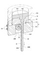
押出しダイス1は、図1,5等に示すように、素材供給側であるメタル供給装置100から押出し供給される上記メタルMを導入する上型ダイ10と、この上型ダイ10を支持すると共に、メタルMを所定の製品用部材の形状に成形する下型ダイ20とを備えて構成されている。
そして、下型ダイ20には、上記製品用部材の一面(表面)にラック状の模様を成形する模様成形具である歯車30が装備されている。
上型ダイ10と下型ダイ20とは、それぞれ略円柱状部材で形成されており、下型ダイ20に対して上型ダイ10が小径に形成されている。
なお、上型ダイ10と下型ダイ20とは、例えば、下型ダイ20の裏面から差し込んだ連結ボルト(図示せず)により連結されている。
押出しダイス1は、図1,5等に示すように、素材供給側であるメタル供給装置100から押出し供給される上記メタルMを導入する上型ダイ10と、この上型ダイ10を支持すると共に、メタルMを所定の製品用部材の形状に成形する下型ダイ20とを備えて構成されている。
そして、下型ダイ20には、上記製品用部材の一面(表面)にラック状の模様を成形する模様成形具である歯車30が装備されている。
上型ダイ10と下型ダイ20とは、それぞれ略円柱状部材で形成されており、下型ダイ20に対して上型ダイ10が小径に形成されている。
なお、上型ダイ10と下型ダイ20とは、例えば、下型ダイ20の裏面から差し込んだ連結ボルト(図示せず)により連結されている。
図5に示すように、上記メタルMは、上型ダイ10の上流側に配置されたチャンバー等を含み構成されている前記メタル供給装置100内に収容され、かつそのメタル供給装置100により押出されるようになっている。
そして、メタルMは、メタル供給装置100内で、例えば、粘土状の柔らかさにされ、かつその状態が維持されるようになっている。また、メタル供給装置100は上型ダイ10を保持している。
そして、メタルMは、メタル供給装置100内で、例えば、粘土状の柔らかさにされ、かつその状態が維持されるようになっている。また、メタル供給装置100は上型ダイ10を保持している。
[上型ダイおよび下型ダイの全体構成]
まず、上型ダイ10の構成について説明する。
上型ダイ10には、図5、図6に示すように、メタル押出し装置100から押出されるメタルMの導入をガイドする第1メタル導入口10Aと、この第1メタル導入口10Aに連続しかつ当該第1メタル導入口10Aより開口が絞られた第2メタル導入口10Bとが形成されている。
まず、上型ダイ10の構成について説明する。
上型ダイ10には、図5、図6に示すように、メタル押出し装置100から押出されるメタルMの導入をガイドする第1メタル導入口10Aと、この第1メタル導入口10Aに連続しかつ当該第1メタル導入口10Aより開口が絞られた第2メタル導入口10Bとが形成されている。
また、上型ダイ10において第2メタル導入口10Bの下流には、この第2メタル導入口10Bに連続し、かつ当該第2メタル導入口10Bより開口が絞られたベアリング部10Cが形成されている。このベアリング部10Cは、前記メタルMを製品用部材である平板40の形状に成形する部位である。
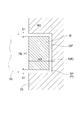
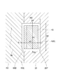
具体的には、図7に示すように、押出される前記メタルMを、断面長方形の縦寸法H1と、横寸法W1とに成形し、上記平板40を形成するようになっている。
具体的には、図7に示すように、押出される前記メタルMを、断面長方形の縦寸法H1と、横寸法W1とに成形し、上記平板40を形成するようになっている。
さらに、上型ダイ10においてベアリング部10Cの下方には、このベアリング部10Cに連続しかつ当該ベアリング部10Cよりも開口が広くなった上側平板ガイド部10Dが形成されている。この上側平板ガイド部10Dは、上記ベアリング部10Cで成形されて押出されてくる上記メタルMを、下型ダイ20側にガイドする部位である。
具体的には、図7に示すように、押出されるメタルMの断面形状、つまり、ベアリング部10Cの縦寸法H1、横寸法W1よりもそれぞれ寸法S1、Sだけ大きな縦寸法H2と、横寸法W2とからなる断面長方形形状の貫通孔となっている。なお、寸法S1、Sは略同じ寸法である。
具体的には、図7に示すように、押出されるメタルMの断面形状、つまり、ベアリング部10Cの縦寸法H1、横寸法W1よりもそれぞれ寸法S1、Sだけ大きな縦寸法H2と、横寸法W2とからなる断面長方形形状の貫通孔となっている。なお、寸法S1、Sは略同じ寸法である。
次に、図3に基づいて下型ダイ20の構成を説明する。
下型ダイ20は、前述のように、略円柱状部材で形成されており、その上面には前記上型ダイ10を載置する際の位置決め用として深さの浅い円形状の凹部20Aが形成されている。
下型ダイ20には、その平面の略中央部近傍に前記歯車30を配置するための歯車配置空間20Bが形成されており、この歯車配置空間20Bは、略長方形形状の貫通穴となっている。
また、この歯車配置空間20Bの長さ方向に沿った両隣には、後述する歯車取付部材32を設置する歯車取付部材設置用穴20Cがそれぞれ形成されている。
下型ダイ20は、前述のように、略円柱状部材で形成されており、その上面には前記上型ダイ10を載置する際の位置決め用として深さの浅い円形状の凹部20Aが形成されている。
下型ダイ20には、その平面の略中央部近傍に前記歯車30を配置するための歯車配置空間20Bが形成されており、この歯車配置空間20Bは、略長方形形状の貫通穴となっている。
また、この歯車配置空間20Bの長さ方向に沿った両隣には、後述する歯車取付部材32を設置する歯車取付部材設置用穴20Cがそれぞれ形成されている。
歯車取付部材設置用穴20Cは、歯車配置空間20Bの長手方向に沿って設けられ、所定幅で全長が寸法Lとなった細長形状で、かつ所定深さに形成されている。
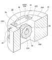
そして、歯車取付部材設置用穴20Cには、上記歯車取付部材32が挿入されるようになっており、この歯車取付部材32は、図10等に示すように、上下一対の上側取付けブロック32Aと下側取付けブロック32Bとで構成されている。
そして、歯車取付部材設置用穴20Cには、上記歯車取付部材32が挿入されるようになっており、この歯車取付部材32は、図10等に示すように、上下一対の上側取付けブロック32Aと下側取付けブロック32Bとで構成されている。
また、下型ダイ20の外周一部には、各歯車取付部材設置用穴20Cの延長上の位置にそれぞれ平面壁部20Dが形成されている。これらの平面壁部20Dは、上記歯車取付部材設置用穴20Cの長さ方向端部の面と平行になっている。
そして、これらの平面壁部20Dと上記歯車取付部材設置用穴20Cの一側面部との間にはネジ孔20Eが切られ、このネジ孔20Eに、後述する歯車位置調整機構を構成する位置調整ボルト35(図4等参照)が螺合されるようになっている。
このネジ孔20Eは、図12、図13等にも示すように、上側取付けブロック32Aと下側取付けブロック32Bとのそれぞれに対応している。
そして、これらの平面壁部20Dと上記歯車取付部材設置用穴20Cの一側面部との間にはネジ孔20Eが切られ、このネジ孔20Eに、後述する歯車位置調整機構を構成する位置調整ボルト35(図4等参照)が螺合されるようになっている。
このネジ孔20Eは、図12、図13等にも示すように、上側取付けブロック32Aと下側取付けブロック32Bとのそれぞれに対応している。
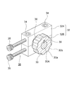
図4には、下型ダイ20の歯車配置空間20Bと歯車取付部材設置用穴20Cとのそれぞれに、前記歯車30と歯車取付部材32とを配置した状態が示されている。
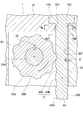
図4に示すように、歯車30は歯車配置空間20Bの左寄りに配置されるようになっており、歯車30の右側には所定の広さの空間SPが設けられており、この空間SPの部位が、前記押出されてくるメタルMの挿通部P(図8も参照)となっている。
図4に示すように、歯車30は歯車配置空間20Bの左寄りに配置されるようになっており、歯車30の右側には所定の広さの空間SPが設けられており、この空間SPの部位が、前記押出されてくるメタルMの挿通部P(図8も参照)となっている。
下型ダイ20には、前記ベアリング部10Cにより成形された平板40を案内する下側平板ガイド部20Fが形成されている。この下側平板ガイド部20Fは、図5に示すように、その上端面から下端面にわたって形成されている。
また、下側平板ガイド部20Fは、図8に示すように断面コ字状に形成されており、断面コ字形状の大きさは、上型ダイ10の上側平板ガイド部10Dと同じ寸法である。ただし、上側平板ガイド部10Dにおける歯車30側の一面が取り除かれた形状と同一形状に形成されている。すなわち、縦寸法がH2、横寸法がW3で形成されている。
また、下側平板ガイド部20Fは、図8に示すように断面コ字状に形成されており、断面コ字形状の大きさは、上型ダイ10の上側平板ガイド部10Dと同じ寸法である。ただし、上側平板ガイド部10Dにおける歯車30側の一面が取り除かれた形状と同一形状に形成されている。すなわち、縦寸法がH2、横寸法がW3で形成されている。
下型ダイ20の上記平板40を間にして上記下側平板ガイド部20Fの反対側領域には、平板40の表面40Aに模様Dを成形する前記歯車30が配設されている。
上記模様Dは、平板40の表面40Aに形成された凹部40aと凸部40bとで形成されており、これらの凹部40aと凸部40bとは、前記歯車30の歯の頂部30aと谷部30bに対応し、これら頂部30aと谷部30bで成形されるようになっている。
上記模様Dは、平板40の表面40Aに形成された凹部40aと凸部40bとで形成されており、これらの凹部40aと凸部40bとは、前記歯車30の歯の頂部30aと谷部30bに対応し、これら頂部30aと谷部30bで成形されるようになっている。
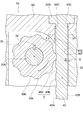
下側平板ガイド部20Fにおいて平板40の裏面40Bと対向する一面と、当該平板40の裏面40Bとの間には所定寸法の前記隙間Sが設けられており、この隙間Sは、歯車30が平板40の表面にラック状の模様Dを成形する際、歯車30の頂部30aによる押圧力を逃がす逃げ部Eを構成している。
そのため、歯車30がその頂部30aにより平板40の表面にラック状の模様Dを成形する際、歯車30の頂部30aが平板40を押圧すると、歯車30による押圧力が逃げ部Eで吸収され、つまり、平板40が押されて下側平板ガイド部20Fに押し付けられる。その結果、平板40の裏面40Bと下側平板ガイド部20Fの一面とが密着しているので、平板40の裏面40Bに生じる凹凸を防止することができる。
そのため、歯車30がその頂部30aにより平板40の表面にラック状の模様Dを成形する際、歯車30の頂部30aが平板40を押圧すると、歯車30による押圧力が逃げ部Eで吸収され、つまり、平板40が押されて下側平板ガイド部20Fに押し付けられる。その結果、平板40の裏面40Bと下側平板ガイド部20Fの一面とが密着しているので、平板40の裏面40Bに生じる凹凸を防止することができる。
上型ダイ10のベアリング部10Cおよび上側平板ガイド部10Dを経由した平板40には、次に述べるように、下型ダイ20の下側平板ガイド部20Fに沿って案内されながら歯車30によるラック状の模様Dが成形される。
[歯車の取付け構成および歯車位置調整機構の構成]
まず、歯車30および歯車の取付け構成の取付け構成について説明する。
歯車30は、前述のように、平板40を間にして下側平板ガイド部20Fの対向位置に配設されている。また、図9、図10等に示すように、歯車30は、その軸部30Aが、取付け部材32を構成する上下一対の取付けブロック32A,32Bで挟み込まれた状態で設けられている。
この取付け部材32は、図12等に示すように、前記歯車取付部材設置用穴20Cに挿入され、かつ平板40側にスライド自在に嵌込まれている。
なお、歯車30と軸部30Aとはキー39で連結されている(図6等参照)。
まず、歯車30および歯車の取付け構成の取付け構成について説明する。
歯車30は、前述のように、平板40を間にして下側平板ガイド部20Fの対向位置に配設されている。また、図9、図10等に示すように、歯車30は、その軸部30Aが、取付け部材32を構成する上下一対の取付けブロック32A,32Bで挟み込まれた状態で設けられている。
この取付け部材32は、図12等に示すように、前記歯車取付部材設置用穴20Cに挿入され、かつ平板40側にスライド自在に嵌込まれている。
なお、歯車30と軸部30Aとはキー39で連結されている(図6等参照)。
図13に示すように、上下一対の取付けブロック32A,32Bは、上側の取付けブロック32Aから差し込まれた連結ボルト34により連結されるようになっている。
また、歯車30の軸部30Aには、高温用軸受36が嵌着されており、この高温用軸受36は、各取付けブロック32A,32Bの長さ方向中央部の凹部32Aa,32Baに嵌め込まれている。
また、歯車30の軸部30Aには、高温用軸受36が嵌着されており、この高温用軸受36は、各取付けブロック32A,32Bの長さ方向中央部の凹部32Aa,32Baに嵌め込まれている。
次に、図12、図13に基づいて、歯車位置調整機構38を説明する。
歯車位置調整機構38は、上側および下側取付けブロック32A,32Bの長さ方向一方側端部と当接する歯車位置調整ボルト35,35と、前記歯車取付け部材設置穴20Cに挿脱自在に設けられる調整用ワッシャー37とで構成されている。
歯車位置調整機構38は、上側および下側取付けブロック32A,32Bの長さ方向一方側端部と当接する歯車位置調整ボルト35,35と、前記歯車取付け部材設置穴20Cに挿脱自在に設けられる調整用ワッシャー37とで構成されている。
上記歯車位置調整ボルト35,35は、下型ダイ20の外周側面に形成されている前記平面壁部20Dから上下一対の取付けブロック32A,32Bのそれぞれの側面に向けて形成されたネジ孔20Eに螺合させることで、各ボルト35,35の先端部を各取付けブロック32A,32Bの長さ方向一方側端部に当接させるようになっている。
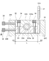
例えば、図12(A)に示すように、歯車位置調整用ボルト35をネジ孔20Eにねじ込むと、ボルト35の先端部が取付けブロック32Aの一方側の側面部に当接する。さらにねじ込むと、取付けブロック32Aが歯車取付け部材設置穴20C内を矢印A方向にスライドし、これにより、歯車30の頂部が平板40の表面に喰い込む量の調整、言い換えれば、歯車30と平板40との距離を調整することができる。
なお、図12(A)では、歯車位置調整用ボルト35を最大限ねじ込んだ状態であり、このとき、取付けブロック32Aの他方側の側面部が歯車取付け部材設置穴20Cの端部に当接している。また、取付けブロック32Aの一方側の側面部と歯車取付け部材設置穴20Cの一方側の側面部との間は、所定寸法Kの隙間となっている。
なお、図12(A)では、歯車位置調整用ボルト35を最大限ねじ込んだ状態であり、このとき、取付けブロック32Aの他方側の側面部が歯車取付け部材設置穴20Cの端部に当接している。また、取付けブロック32Aの一方側の側面部と歯車取付け部材設置穴20Cの一方側の側面部との間は、所定寸法Kの隙間となっている。
図12(B)には、歯車30の頂部が平板40の表面に喰い込む量を少なくする場合の調整方法が示されている。
この場合、歯車位置調整用ボルト35を逆方向に回すと、取付けブロック32Aが歯車取付け部材設置穴20C内を矢印B方向にスライド自在となる。そこで、まず、上記所定寸法Kの隙間がなくなるまで歯車位置調整用ボルト35を逆方向に回す。
この場合、歯車位置調整用ボルト35を逆方向に回すと、取付けブロック32Aが歯車取付け部材設置穴20C内を矢印B方向にスライド自在となる。そこで、まず、上記所定寸法Kの隙間がなくなるまで歯車位置調整用ボルト35を逆方向に回す。
次いで、矢印Bで示すように、歯車30を手で掴んで歯車位置調整用ボルト35側に引き寄せる。その後、歯車30の頂部の平板40への設定された喰い込み量となるように、他方側の側面の寸法K2の隙間に調整用ワッシャー37を挿入しておいて、歯車位置調整用ボルト35を取付けブロック32Aの側面に当接するまでねじ込む。
このとき、取付けブロック32Aと歯車取付け部材設置穴20Cの側面との間の隙間K1と、取付けブロック32Aと歯車取付け部材設置穴20Cの他方側の側面の隙間K2とを合わせた寸法は、上記図12(A)における隙間Kと同じである。
このとき、取付けブロック32Aと歯車取付け部材設置穴20Cの側面との間の隙間K1と、取付けブロック32Aと歯車取付け部材設置穴20Cの他方側の側面の隙間K2とを合わせた寸法は、上記図12(A)における隙間Kと同じである。
また、図12(A)、図12(B)においては、取付けブロック32のうち、上側の取付けブロック32Aを説明したが、前述のように、上側の取付けブロック32Aと下側の取付けブロック32Bとは連結ボルト34で一体的に固定されているので、両取付けブロック32A,32Bの動作は全く同じである。
ここで、歯車位置調整用ボルト35,35は、上下一対の取付けブロック32A,32Bのそれぞれに対応して設けられているが、いずれか一方の歯車位置調整用ボルト35を操作するだけでもよい。
ここで、歯車位置調整用ボルト35,35は、上下一対の取付けブロック32A,32Bのそれぞれに対応して設けられているが、いずれか一方の歯車位置調整用ボルト35を操作するだけでもよい。
図13に示すように、上記調整用ワッシャー37は、所定厚さ寸法に仕上げられたプレートで形成されており、調整用ワッシャー37は、歯車30の頂部30aの平板40に対する喰い込み量を調整できるように、厚さの異なる複数種類のプレートが予め準備されている。
この調整用ワッシャー37は、上側の調整部材32Aと下側の調整部材32Bとを合わせた厚さと略同じ寸法の長さに形成されている。
この調整用ワッシャー37は、上側の調整部材32Aと下側の調整部材32Bとを合わせた厚さと略同じ寸法の長さに形成されている。
また、調整用ワッシャー37の上端部には、図12(A)および図13に示すように、幅方向両端部に把持部37Aが形成されている。この把持部37Aは、調整用ワッシャー37を歯車取付け部材設置穴20C内に挿入させる際に、所定の挟み具(治具)で挟んで作業するために形成されている。
[押出しダイスによる平板の成形方法]
次に、以上のような構成の押出しダイス1による平板40の成形方法を説明する。
作業に先立って、平板40の表面にラック状の模様Dを成形するための歯車30を下型ダイ20にセットしておく。
このとき、歯車30の頂部30aが平板40の表面に喰いこむ量、つまり凹部40bおよび凸部40aの高さ寸法を所望の寸法とするため、歯車位置調整ボルト35,35により歯車30の位置を設定しておく。
次に、以上のような構成の押出しダイス1による平板40の成形方法を説明する。
作業に先立って、平板40の表面にラック状の模様Dを成形するための歯車30を下型ダイ20にセットしておく。
このとき、歯車30の頂部30aが平板40の表面に喰いこむ量、つまり凹部40bおよび凸部40aの高さ寸法を所望の寸法とするため、歯車位置調整ボルト35,35により歯車30の位置を設定しておく。
メタル供給装置100から上型ダイ10の第1メタル導入口10AにメタルMが導入され、さらに、第2メタル導入口10Bを経由して下流側に押し出されると、上型ダイ10のベアリング部10Cで平板40の形状に成形され、その平板40はベアリング部10Cから上型ダイ10の上側平板ガイド部10Dから下型ダイ20に押出される。
下型ダイ20に押出された平板40は、下型ダイ20の下側平板ガイド部20Fにガイドされながら下方に押し出される途中で、メタルMの押出しに伴って回転する歯車30により、平板40の表面にラック状の模様Dが連続して成形される。
下型ダイ20に押出された平板40は、下型ダイ20の下側平板ガイド部20Fにガイドされながら下方に押し出される途中で、メタルMの押出しに伴って回転する歯車30により、平板40の表面にラック状の模様Dが連続して成形される。
前述したように、歯車30の頂部30aが、上型ダイ10から押出される平板40の表面に喰い込むとき、その押圧力が平板40に伝わるため、平板40が歯車30と対向する反対側に押される。しかし、下型ダイ20の歯車30と対向する反対側の面、つまり前記下側平板ガイド部20Fの一面と平板40の裏面との間には、隙間Sの逃げ部Eが広い範囲にわたって設けられているので、押された平板40はその裏面40Bが側平板ガイド部20Fの一面に押し付けられる。
すなわち、歯車30による平板40への押圧力は逃げ部Eで吸収された状態となる。
すなわち、歯車30による平板40への押圧力は逃げ部Eで吸収された状態となる。
歯車30の頂部30aによる喰い込み量を変えたい場合、例えば、喰い込む量を少なくする場合には、歯車位置調整用ボルト35を逆方向に回して、取付けブロック32A,32Bが歯車取付け部材設置穴20C内をスライド可能とする。
次いで、歯車30を位置調整用ボルト35側に引き寄せた後、歯車30の頂部30aによる所定の喰い込み量となるように、歯車取付け部材設置穴20C内に所定の調整用ワッシャー37を挿入し、歯車位置調整用ボルト35を取付けブロック32Aの側面に当接するまでねじ込む。
次いで、歯車30を位置調整用ボルト35側に引き寄せた後、歯車30の頂部30aによる所定の喰い込み量となるように、歯車取付け部材設置穴20C内に所定の調整用ワッシャー37を挿入し、歯車位置調整用ボルト35を取付けブロック32Aの側面に当接するまでねじ込む。
そうしておいて、前述のように、メタル供給装置100を操作して、アルミニウム合金Mを押出しダイス1に供給して、歯車30により平板40の表面に凹凸模様Dを成形する。そして、所定の製品長さとなるまでその作業が継続される。
本実施形態の押出しダイス1は以上のように構成されているので、次のような効果を得ることができる。
(1)上型ダイ10のベアリング部10Cにより成形された状態で押出される平板40が下型ダイ20の下側平板ガイド部20Fに沿って移動する途中において、歯車30により平板40の表面に模様Dが成形される。このとき、歯車30の頂部30aが平板40表面を押圧するが、下側平板ガイド部20Fと平板40の裏面40Bとの間に逃げ部Eが形成されているので、平板40にかかる押圧力が逃げ部Eで吸収された状態で、下側平板ガイド部20Fに押し付けられる。その結果、平板40の裏面40Bと下側平板ガイド部20Fとが密着するので、平板40の裏面40Bに凹凸模様Dが生じることを防止することができる。
(1)上型ダイ10のベアリング部10Cにより成形された状態で押出される平板40が下型ダイ20の下側平板ガイド部20Fに沿って移動する途中において、歯車30により平板40の表面に模様Dが成形される。このとき、歯車30の頂部30aが平板40表面を押圧するが、下側平板ガイド部20Fと平板40の裏面40Bとの間に逃げ部Eが形成されているので、平板40にかかる押圧力が逃げ部Eで吸収された状態で、下側平板ガイド部20Fに押し付けられる。その結果、平板40の裏面40Bと下側平板ガイド部20Fとが密着するので、平板40の裏面40Bに凹凸模様Dが生じることを防止することができる。
(2)上記(1)の効果の他、平板40の裏面40Bに凹凸のない模様付製品を生産することができるので、材料の無駄や作業時間の無駄を省くことができる。その結果、生産性の向上を図ることができる。
(3)平板40の裏面40Bに凹凸のない模様付製品を生産することができるので、意匠性の向上を図ることができる。
(4)歯車30を取付けた歯車取付け部材32は歯車取付け部材20Cに挿入され、下型ダイ20には、歯車取付け部材32を歯車取付け部材20C内で平板40の移動方向に対して直交する方向に沿ってスライドさせる歯車位置調整ボルト35が設けられているので、この歯車位置調整ボルト35を操作することにより、歯車30の位置を調整することができる。
その結果、歯車30の頂部30aの平板40への喰い込み量を調整することができるので、ラック状の模様Dの深さを容易に任意の深さとすることができる。
その結果、歯車30の頂部30aの平板40への喰い込み量を調整することができるので、ラック状の模様Dの深さを容易に任意の深さとすることができる。
(5)上型ダイ10には、ベアリング部10Cの下部に連続する上側平板ガイド部10Dが設けられており、この上側平板ガイド部10Dは、精密な加工が要求されるベアリング部10Cほどの加工が不要なので、上側平板ガイド部10Dの加工が容易である。
次に、図15~17を参照して、本発明の押出しダイスの第2の実施形態を説明する。
本第2の実施形態の押出しダイス50における上型ダイ60は、前記上型ダイ10の下面に歯車30側に向けて突出した突出部60Eを設けた形状としたものである。他の構成は、前記下型ダイ20を含み第1の実施形態と全く同じである。したがって、同一構成の部材等には同一符号を付し、それらの詳細な説明は省略する。
本第2の実施形態の押出しダイス50における上型ダイ60は、前記上型ダイ10の下面に歯車30側に向けて突出した突出部60Eを設けた形状としたものである。他の構成は、前記下型ダイ20を含み第1の実施形態と全く同じである。したがって、同一構成の部材等には同一符号を付し、それらの詳細な説明は省略する。
図15,16に示すように、上型ダイ60には、上述のように、上型ダイ60の下面から前記下型ダイ20の歯車30側に向けて突出し、かつ平板40の表面と対向する突出部60Eが設けられている。この突出部60Eは、歯車30の上部側の外周一部に沿って、かつ外周一部を覆った状態で形成されている。
そして、この突出部60Eの前記平板40の表面と対向する面には、前記ベアリング部10Cに相当するベアリング部60Cの下部に形成され、かつ当該ベアリング部60Cに連続する上側平板ガイド部60Dが設けられている。この上側平板ガイド部60Dは、ベアリング部60Cで成形された平板40を下型ダイ20の歯車30側にガイドするものである。
上側平板ガイド部60Eは、図17に示すように、前記下側平板ガイド部20Fの縦寸法H2と同じ寸法で、かつ平板40の幅寸法W1(ベアリング部60Cの幅寸法)から寸法Sだけ離れた形状の溝部で形成されている。
つまり、上側平板ガイド部60Eは下側平板ガイド部20Fと連続しており、図17に示す断面形状は、図7に示す前記上側平板ガイド部10Dの断面形状と略同一である。
なお、上型ダイ60には、メタル第1導入口60Aと、その下方に形成されたメタル第2導入口60Bが設けられている。
つまり、上側平板ガイド部60Eは下側平板ガイド部20Fと連続しており、図17に示す断面形状は、図7に示す前記上側平板ガイド部10Dの断面形状と略同一である。
なお、上型ダイ60には、メタル第1導入口60Aと、その下方に形成されたメタル第2導入口60Bが設けられている。
本第2の実施形態の押出しダイス50によれば、前記第1の実施形態の(1)~(5)と同様の効果を得ることができる他、次のような効果を得ることができる。
(6)上型ダイ60の歯車30の上方領域には、上型ダイ60の下面から歯車30の上方を覆って下方に突出し、かつ一面が平板40と対向する突出部60Eが設けられ、この突出部60Eの一面には、平板40を下型ダイ30の歯車30側にガイドする上側平板ガイド部60Eが設けられ、この上側平板ガイド部60Eは、歯車30の頂部30aが平板40の表面に喰い込む位置の近傍まで延びているので、平板40を歯車30による模様Dの成形位置に確実に導入させることができる。
(6)上型ダイ60の歯車30の上方領域には、上型ダイ60の下面から歯車30の上方を覆って下方に突出し、かつ一面が平板40と対向する突出部60Eが設けられ、この突出部60Eの一面には、平板40を下型ダイ30の歯車30側にガイドする上側平板ガイド部60Eが設けられ、この上側平板ガイド部60Eは、歯車30の頂部30aが平板40の表面に喰い込む位置の近傍まで延びているので、平板40を歯車30による模様Dの成形位置に確実に導入させることができる。
以上、前記各実施形態を参照して本願発明を説明したが、本願発明は前記各実施形態に限定されるものではない。本願発明の構成や詳細については、当業者が理解し得るさまざまな変更を加えることができる。また、本願発明には、上記各実施形態の構成の一部又は全部を相互に適宜組み合わせたものも含まれる。
例えば、前記各実施形態では、歯車30により平板40の表面にラック状の模様 を成形したが、模様はラック状に限らない。歯車状の回転部材の表面に、波型模様や、押出し方向に対して上流側、または交流側に先端部が向いた鏃状の模様など、意匠性の向上や滑り止め機能を強化した模様であればどのような模様でもよい。
また、前記各実施形態では、熱可塑性材料として、アルミニウム合金が使用されているが、これに限らず、PP(ポリプロピレン)、PE(ポリエチレン)等の汎用プラスチックや、PA(ポリアミド)等のエンジニアリング・プラスチック等の合成樹脂を使用してもよい。
さらに、前記各実施形態では、押出しダイス1,50に対して、アルミニウム合金からなるメタルMを上方側から供給する縦型構成としたが、これに限らない。例えば、押出しダイス1,50を水平方向に配置し、メタルMを横側から供給する横型構成としてもよい。
また、前記各実施形態では、歯車30の平板40に対する取付け位置の調整を、歯車位置調整用ボルト35による歯車取付け部材32のスライドと、調整用ワッシャー37とを使用して行っていたが、これに限らない。例えば、歯車取付け部材設置穴20Cの歯車位置調整用ボルト35の反対側側面に、例えば板バネを設置したり、あるいは圧縮コイルバネを下型ダイに埋め込んだ構成としてもよい。
このようにした場合、調整用ワッシャー37を着脱する手間を省くことができる。
このようにした場合、調整用ワッシャー37を着脱する手間を省くことができる。
また、前記各実施形態では、下側平板ガイド部20Fを、下型ダイ20の上端から下端にわたって連続して形成したが、これに限らない。下側平板ガイド部を、例えば、下型ダイ20において、当該下型ダイ20の上端から、少なくとも歯車30の頂部30aと水平方向の対向部にわたって形成してもよい。
本願発明の模様付製品成形用押出しダイスは、熱可塑性材料の表面に所定の模様を成形する際に利用される。
1 模様付製品成形用押出しダイス
10 上型ダイ
10C ベアリング部
10D 上側平板ガイド部
20 下型ダイ
20B 歯車配置空間
20C 歯車取付部材設置空間
20F 下側平板ガイド部
30 歯車
30a 歯車の頂部
32 歯車取付部材
32A 上側取付けブロック
32B 下側取付けブロック
35 歯車位置調整ボルト(歯車位置調整機構)
37 調整用ワッシャー(歯車位置調整機構)
40 平板(製品用部材)
50 模様付製品成形用押出しダイス(第2実施形態)
60 上型ダイ
60C ベアリング部
60D 上側平板ガイド部
60E 突出部
M メタル(アルミニウム合金)
10 上型ダイ
10C ベアリング部
10D 上側平板ガイド部
20 下型ダイ
20B 歯車配置空間
20C 歯車取付部材設置空間
20F 下側平板ガイド部
30 歯車
30a 歯車の頂部
32 歯車取付部材
32A 上側取付けブロック
32B 下側取付けブロック
35 歯車位置調整ボルト(歯車位置調整機構)
37 調整用ワッシャー(歯車位置調整機構)
40 平板(製品用部材)
50 模様付製品成形用押出しダイス(第2実施形態)
60 上型ダイ
60C ベアリング部
60D 上側平板ガイド部
60E 突出部
M メタル(アルミニウム合金)
Claims (8)
- 素材供給側から連続して押出される熱可塑性部材で形成される製品用部材の表面に模様を成形する模様付製品成形用押出しダイスであって、
前記熱可塑性部材を導入する上型ダイと、この上型ダイを支持する下型ダイと、を備えて構成され、
前記上型ダイは、前記熱可塑性部材を前記製品用部材の形状に成形するベアリング部を有し、
前記下型ダイには、前記ベアリング部により成形された前記製品用部材の移動を案内する製品部材用下側ガイド部と、前記製品用部材の一面に前記模様を成形する模様成形具とが設けられ、
前記製品部材用下側ガイド部には、前記模様成形具による模様成形時の押圧力を吸収する逃げ部が形成されていることを特徴とする模様付製品成形用押出しダイス。 - 請求項1に記載の模様付製品成形用押出しダイスにおいて、
前記上型ダイの前記模様成形具の上方領域には、前記上型ダイの下面から前記模様成形具の上面を覆って下方に突出しかつ一面が前記製品用部材と対向する突出部が設けられ、
この突出部の前記一面には、前記ベアリング部の下部に形成されると共に当該ベアリング部に連続しかつ当該ベアリング部で成形された前記製品用部材を前記下型ダイの前記模様成形具側にガイドする製品部材用上側ガイド部が設けられていることを特徴とする模様付製品成形用押出しダイス。 - 請求項1または2に記載の模様付製品成形用押出しダイスにおいて、
前記逃げ部は、前記下型ダイの上面から下面にわたって連続して形成されていることを特徴とする模様付製品成形用押出しダイス。 - 請求項1ないし3のいずれか一項に記載の模様付製品成形用押出しダイスにおいて、
前記逃げ部は、前記製品部材用下側ガイド部の前記模様成形具と対向する一面とこの製品部材用下側ガイド部の一面の上方に同列上に位置する前記ベアリング部の一面との間の水平方向での間隔で構成され、
前記製品部材用下側ガイド部の一面が前記ベアリング部の一面に対して外側に後退していることを特徴とする模様付製品成形用押出しダイス。 - 請求項1ないし4のいずれか一項に記載の模様付製品成形用押出しダイスにおいて、
前記模様成形具は、前記製品用部材の移動とともに回転する歯車で構成されていることを特徴とする模様付製品成形用押出しダイス。 - 請求項5に記載の模様付製品成形用押出しダイスにおいて、
前記歯車は、当該歯車の主軸両端がそれぞれ軸受けを介して歯車取付け部材に支持され、
前記両歯車取付け部材は、前記下型ダイに形成された歯車取付け部材設置用穴にそれぞれ設置され、
前記下型ダイには、前記各歯車取付け部材を前記製品用部材の移動方向に対して直交する方向に沿ってスライドさせ前記歯車の前記製品用部材に対する位置を調整する歯車位置調整機構が設けられていることを特徴とする模様付製品成形用押出しダイス。 - 請求項1ないし6のいずれか一項に記載の模様付製品成形用押出しダイスにおいて、
前記上型ダイには、前記ベアリング部の下部に連続しかつ当該ベアリング部で形状が決定された前記製品用部材を前記下型ダイ側にガイドする製品部材用上側ガイド部が設けられていることを特徴とする模様付製品成形用押出しダイス。 - 請求項1ないし7のいずれか一項に記載の模様付製品成形用押出しダイスにおいて、
前記熱可塑性部材は、アルミニウム合金であることを特徴とする模様付製品成形用押出しダイス。
Priority Applications (1)
| Application Number | Priority Date | Filing Date | Title |
|---|---|---|---|
| CN202080017904.9A CN113507991B (zh) | 2019-03-11 | 2020-03-06 | 带图案制品的成型用压出模具 |
Applications Claiming Priority (2)
| Application Number | Priority Date | Filing Date | Title |
|---|---|---|---|
| JP2019044294A JP7104268B2 (ja) | 2019-03-11 | 2019-03-11 | 模様付製品成形用押出しダイス |
| JP2019-044294 | 2019-03-11 |
Publications (1)
| Publication Number | Publication Date |
|---|---|
| WO2020184411A1 true WO2020184411A1 (ja) | 2020-09-17 |
Family
ID=72427500
Family Applications (1)
| Application Number | Title | Priority Date | Filing Date |
|---|---|---|---|
| PCT/JP2020/009576 Ceased WO2020184411A1 (ja) | 2019-03-11 | 2020-03-06 | 模様付製品成形用押出しダイス |
Country Status (3)
| Country | Link |
|---|---|
| JP (1) | JP7104268B2 (ja) |
| CN (1) | CN113507991B (ja) |
| WO (1) | WO2020184411A1 (ja) |
Cited By (1)
| Publication number | Priority date | Publication date | Assignee | Title |
|---|---|---|---|---|
| WO2024070041A1 (ja) * | 2022-09-27 | 2024-04-04 | 日本軽金属株式会社 | 模様付製品成形用押出しダイス |
Citations (3)
| Publication number | Priority date | Publication date | Assignee | Title |
|---|---|---|---|---|
| JP2003522647A (ja) * | 2000-02-18 | 2003-07-29 | マルクラム ディベロップメント アクチボラゲット | 塑性変形可能な素材のプレス加工装置および方法 |
| JP2011504420A (ja) * | 2007-11-26 | 2011-02-10 | アルシジオ エービー | 回転ダイを用いるプロファイル製造のためのデバイスと方法 |
| JP2017074617A (ja) * | 2015-10-13 | 2017-04-20 | 財団法人金属工業研究発展中心 | 不均一断面を備えた押出成形材を製造するための押出成形装置及び押出成形方法 |
Family Cites Families (3)
| Publication number | Priority date | Publication date | Assignee | Title |
|---|---|---|---|---|
| JPS58119842A (ja) * | 1982-01-12 | 1983-07-16 | Inax Corp | 押出体の模様付与方法 |
| AT503550B1 (de) * | 2006-05-31 | 2007-11-15 | Amag Extrusion Gmbh | Extrudiertes profil, insbesondere bodenprofil |
| SE539862C2 (sv) * | 2015-07-04 | 2017-12-27 | Arsizio Ab | Anordning samt förfarande för extrusion med motstående roterande organ |
-
2019
- 2019-03-11 JP JP2019044294A patent/JP7104268B2/ja active Active
-
2020
- 2020-03-06 CN CN202080017904.9A patent/CN113507991B/zh active Active
- 2020-03-06 WO PCT/JP2020/009576 patent/WO2020184411A1/ja not_active Ceased
Patent Citations (3)
| Publication number | Priority date | Publication date | Assignee | Title |
|---|---|---|---|---|
| JP2003522647A (ja) * | 2000-02-18 | 2003-07-29 | マルクラム ディベロップメント アクチボラゲット | 塑性変形可能な素材のプレス加工装置および方法 |
| JP2011504420A (ja) * | 2007-11-26 | 2011-02-10 | アルシジオ エービー | 回転ダイを用いるプロファイル製造のためのデバイスと方法 |
| JP2017074617A (ja) * | 2015-10-13 | 2017-04-20 | 財団法人金属工業研究発展中心 | 不均一断面を備えた押出成形材を製造するための押出成形装置及び押出成形方法 |
Cited By (1)
| Publication number | Priority date | Publication date | Assignee | Title |
|---|---|---|---|---|
| WO2024070041A1 (ja) * | 2022-09-27 | 2024-04-04 | 日本軽金属株式会社 | 模様付製品成形用押出しダイス |
Also Published As
| Publication number | Publication date |
|---|---|
| CN113507991A (zh) | 2021-10-15 |
| CN113507991B (zh) | 2023-03-10 |
| JP7104268B2 (ja) | 2022-07-21 |
| JP2020146697A (ja) | 2020-09-17 |
Similar Documents
| Publication | Publication Date | Title |
|---|---|---|
| JP2018523579A (ja) | 向き合った回転ダイを利用する異形材の押出成形 | |
| JP7420026B2 (ja) | 模様付製品成形用押出しダイス | |
| JP7104268B2 (ja) | 模様付製品成形用押出しダイス | |
| DE102005048440A1 (de) | Schneidemaschine und Herstellungssystem für Platten mit fester Größe | |
| CN201008901Y (zh) | 一种具有异形孔台阶齿轮一次成形模具 | |
| CN210098598U (zh) | 一种开口可调的无压痕折弯下模具 | |
| CN210788959U (zh) | 一种自动送料冲床机构 | |
| JP7484413B2 (ja) | 模様付製品成形用押出しダイス | |
| JP7480640B2 (ja) | 形材成形用押出しダイス | |
| JP2000210732A (ja) | プレス打ち抜き製品のバリなし加工方法 | |
| KR20090092921A (ko) | 개선된 인서트 전조 다이와 이를 통한 인서트의 생산방법 | |
| CN211991909U (zh) | 一种模具钢铣床加工用防变形组件 | |
| CN223630162U (zh) | 一种模具加工去毛刺装置 | |
| CN113172156A (zh) | 一种下模结构及折弯模具 | |
| CN210435112U (zh) | 一种三角异形棒加工模具 | |
| WO2024070041A1 (ja) | 模様付製品成形用押出しダイス | |
| CN211614020U (zh) | 弯通侧板冲孔成型工作台 | |
| CN215998310U (zh) | 冲压成型模具的可调整上模结构 | |
| CN219724330U (zh) | 一种具有定位功能的模具 | |
| CN224181679U (zh) | 一种焊带辊压装置 | |
| CN212528835U (zh) | 一种可调节定位工装 | |
| CN221232432U (zh) | 一种门窗型材定位工装 | |
| JP4969466B2 (ja) | 押出成形機の金型 | |
| CN110014200B (zh) | 一种走丝机的夹紧装置 | |
| CN220921111U (zh) | 一种铝模生产用导向定位功能的锯床结构 |
Legal Events
| Date | Code | Title | Description |
|---|---|---|---|
| 121 | Ep: the epo has been informed by wipo that ep was designated in this application |
Ref document number: 20770520 Country of ref document: EP Kind code of ref document: A1 |
|
| NENP | Non-entry into the national phase |
Ref country code: DE |
|
| 122 | Ep: pct application non-entry in european phase |
Ref document number: 20770520 Country of ref document: EP Kind code of ref document: A1 |