WO2020184143A1 - 電極、レドックスフロー電池、電極の製造方法、及び電極の再生方法 - Google Patents
電極、レドックスフロー電池、電極の製造方法、及び電極の再生方法 Download PDFInfo
- Publication number
- WO2020184143A1 WO2020184143A1 PCT/JP2020/006943 JP2020006943W WO2020184143A1 WO 2020184143 A1 WO2020184143 A1 WO 2020184143A1 JP 2020006943 W JP2020006943 W JP 2020006943W WO 2020184143 A1 WO2020184143 A1 WO 2020184143A1
- Authority
- WO
- WIPO (PCT)
- Prior art keywords
- electrode
- porous body
- reactive particles
- battery
- electrolytic solution
- Prior art date
Links
Images


Classifications
-
- H—ELECTRICITY
- H01—ELECTRIC ELEMENTS
- H01M—PROCESSES OR MEANS, e.g. BATTERIES, FOR THE DIRECT CONVERSION OF CHEMICAL ENERGY INTO ELECTRICAL ENERGY
- H01M4/00—Electrodes
- H01M4/86—Inert electrodes with catalytic activity, e.g. for fuel cells
- H01M4/90—Selection of catalytic material
- H01M4/92—Metals of platinum group
- H01M4/921—Alloys or mixtures with metallic elements
-
- H—ELECTRICITY
- H01—ELECTRIC ELEMENTS
- H01M—PROCESSES OR MEANS, e.g. BATTERIES, FOR THE DIRECT CONVERSION OF CHEMICAL ENERGY INTO ELECTRICAL ENERGY
- H01M4/00—Electrodes
- H01M4/86—Inert electrodes with catalytic activity, e.g. for fuel cells
- H01M4/8605—Porous electrodes
-
- H—ELECTRICITY
- H01—ELECTRIC ELEMENTS
- H01M—PROCESSES OR MEANS, e.g. BATTERIES, FOR THE DIRECT CONVERSION OF CHEMICAL ENERGY INTO ELECTRICAL ENERGY
- H01M4/00—Electrodes
- H01M4/86—Inert electrodes with catalytic activity, e.g. for fuel cells
- H01M4/8605—Porous electrodes
- H01M4/8615—Bifunctional electrodes for rechargeable cells
-
- H—ELECTRICITY
- H01—ELECTRIC ELEMENTS
- H01M—PROCESSES OR MEANS, e.g. BATTERIES, FOR THE DIRECT CONVERSION OF CHEMICAL ENERGY INTO ELECTRICAL ENERGY
- H01M4/00—Electrodes
- H01M4/86—Inert electrodes with catalytic activity, e.g. for fuel cells
- H01M4/8647—Inert electrodes with catalytic activity, e.g. for fuel cells consisting of more than one material, e.g. consisting of composites
-
- H—ELECTRICITY
- H01—ELECTRIC ELEMENTS
- H01M—PROCESSES OR MEANS, e.g. BATTERIES, FOR THE DIRECT CONVERSION OF CHEMICAL ENERGY INTO ELECTRICAL ENERGY
- H01M4/00—Electrodes
- H01M4/86—Inert electrodes with catalytic activity, e.g. for fuel cells
- H01M4/8663—Selection of inactive substances as ingredients for catalytic active masses, e.g. binders, fillers
- H01M4/8668—Binders
-
- H—ELECTRICITY
- H01—ELECTRIC ELEMENTS
- H01M—PROCESSES OR MEANS, e.g. BATTERIES, FOR THE DIRECT CONVERSION OF CHEMICAL ENERGY INTO ELECTRICAL ENERGY
- H01M4/00—Electrodes
- H01M4/86—Inert electrodes with catalytic activity, e.g. for fuel cells
- H01M4/90—Selection of catalytic material
- H01M4/9041—Metals or alloys
-
- H—ELECTRICITY
- H01—ELECTRIC ELEMENTS
- H01M—PROCESSES OR MEANS, e.g. BATTERIES, FOR THE DIRECT CONVERSION OF CHEMICAL ENERGY INTO ELECTRICAL ENERGY
- H01M4/00—Electrodes
- H01M4/86—Inert electrodes with catalytic activity, e.g. for fuel cells
- H01M4/90—Selection of catalytic material
- H01M4/9091—Unsupported catalytic particles; loose particulate catalytic materials, e.g. in fluidised state
-
- H—ELECTRICITY
- H01—ELECTRIC ELEMENTS
- H01M—PROCESSES OR MEANS, e.g. BATTERIES, FOR THE DIRECT CONVERSION OF CHEMICAL ENERGY INTO ELECTRICAL ENERGY
- H01M4/00—Electrodes
- H01M4/86—Inert electrodes with catalytic activity, e.g. for fuel cells
- H01M4/90—Selection of catalytic material
- H01M4/92—Metals of platinum group
- H01M4/928—Unsupported catalytic particles; loose particulate catalytic materials, e.g. in fluidised state
-
- H—ELECTRICITY
- H01—ELECTRIC ELEMENTS
- H01M—PROCESSES OR MEANS, e.g. BATTERIES, FOR THE DIRECT CONVERSION OF CHEMICAL ENERGY INTO ELECTRICAL ENERGY
- H01M8/00—Fuel cells; Manufacture thereof
- H01M8/02—Details
- H01M8/0202—Collectors; Separators, e.g. bipolar separators; Interconnectors
- H01M8/023—Porous and characterised by the material
- H01M8/0232—Metals or alloys
-
- H—ELECTRICITY
- H01—ELECTRIC ELEMENTS
- H01M—PROCESSES OR MEANS, e.g. BATTERIES, FOR THE DIRECT CONVERSION OF CHEMICAL ENERGY INTO ELECTRICAL ENERGY
- H01M8/00—Fuel cells; Manufacture thereof
- H01M8/18—Regenerative fuel cells, e.g. redox flow batteries or secondary fuel cells
- H01M8/184—Regeneration by electrochemical means
- H01M8/188—Regeneration by electrochemical means by recharging of redox couples containing fluids; Redox flow type batteries
-
- H—ELECTRICITY
- H01—ELECTRIC ELEMENTS
- H01M—PROCESSES OR MEANS, e.g. BATTERIES, FOR THE DIRECT CONVERSION OF CHEMICAL ENERGY INTO ELECTRICAL ENERGY
- H01M4/00—Electrodes
- H01M4/86—Inert electrodes with catalytic activity, e.g. for fuel cells
- H01M4/90—Selection of catalytic material
- H01M4/9016—Oxides, hydroxides or oxygenated metallic salts
-
- H—ELECTRICITY
- H01—ELECTRIC ELEMENTS
- H01M—PROCESSES OR MEANS, e.g. BATTERIES, FOR THE DIRECT CONVERSION OF CHEMICAL ENERGY INTO ELECTRICAL ENERGY
- H01M4/00—Electrodes
- H01M4/86—Inert electrodes with catalytic activity, e.g. for fuel cells
- H01M4/90—Selection of catalytic material
- H01M4/92—Metals of platinum group
- H01M4/923—Compounds thereof with non-metallic elements
-
- H—ELECTRICITY
- H01—ELECTRIC ELEMENTS
- H01M—PROCESSES OR MEANS, e.g. BATTERIES, FOR THE DIRECT CONVERSION OF CHEMICAL ENERGY INTO ELECTRICAL ENERGY
- H01M8/00—Fuel cells; Manufacture thereof
- H01M8/02—Details
- H01M8/0202—Collectors; Separators, e.g. bipolar separators; Interconnectors
- H01M8/023—Porous and characterised by the material
- H01M8/0234—Carbonaceous material
-
- H—ELECTRICITY
- H01—ELECTRIC ELEMENTS
- H01M—PROCESSES OR MEANS, e.g. BATTERIES, FOR THE DIRECT CONVERSION OF CHEMICAL ENERGY INTO ELECTRICAL ENERGY
- H01M8/00—Fuel cells; Manufacture thereof
- H01M8/02—Details
- H01M8/0202—Collectors; Separators, e.g. bipolar separators; Interconnectors
- H01M8/023—Porous and characterised by the material
- H01M8/0239—Organic resins; Organic polymers
-
- Y—GENERAL TAGGING OF NEW TECHNOLOGICAL DEVELOPMENTS; GENERAL TAGGING OF CROSS-SECTIONAL TECHNOLOGIES SPANNING OVER SEVERAL SECTIONS OF THE IPC; TECHNICAL SUBJECTS COVERED BY FORMER USPC CROSS-REFERENCE ART COLLECTIONS [XRACs] AND DIGESTS
- Y02—TECHNOLOGIES OR APPLICATIONS FOR MITIGATION OR ADAPTATION AGAINST CLIMATE CHANGE
- Y02E—REDUCTION OF GREENHOUSE GAS [GHG] EMISSIONS, RELATED TO ENERGY GENERATION, TRANSMISSION OR DISTRIBUTION
- Y02E60/00—Enabling technologies; Technologies with a potential or indirect contribution to GHG emissions mitigation
- Y02E60/30—Hydrogen technology
- Y02E60/50—Fuel cells
Definitions
- the present disclosure relates to electrodes, redox flow batteries, methods for manufacturing electrodes, and methods for regenerating electrodes.
- This application claims priority based on Japanese Patent Application No. 2019-045261 of the Japanese application dated March 12, 2019, and incorporates all the contents described in the Japanese application.
- a woven fabric or non-woven fabric made of carbon fiber that is, carbon cloth, carbon felt, or the like is used for the electrode of the battery cell.
- the electrodes according to the present disclosure are It is an electrode of a redox flow battery that circulates an electrolytic solution. Porous medium and It has reactive particles that contribute to the battery reaction, The reactive particles are pressed against the porous body by the flow of the electrolytic solution without being fixed to the porous body.
- the redox flow battery according to the present disclosure is Battery cell and The battery cell is provided with a circulation mechanism for circulating the electrolytic solution.
- the battery cell is a redox flow battery having a positive electrode, a negative electrode, and a diaphragm interposed between the positive electrode and the negative electrode.
- At least one of the positive electrode and the negative electrode Porous medium and It has reactive particles that contribute to the battery reaction, The reactive particles are pressed against the porous body by the flow of the electrolytic solution without being fixed to the porous body.
- the electrode manufacturing method according to the present disclosure is described.
- the process of preparing the battery cell of the redox flow battery containing the porous material, and The present invention includes a step of pressing the reactive particles without being fixed to the porous body by circulating an electrolytic solution containing reactive particles that contribute to the battery reaction to the porous body.
- the electrode regeneration method according to the present disclosure is described.
- the step of measuring the cell resistance of the battery cell and A step of replenishing the reactive particles with the electrolytic solution based on the measurement result of the cell resistance is provided.
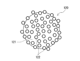
- FIG. 1 is a perspective view showing an outline of electrodes provided in the redox flow battery according to the first embodiment.
- FIG. 2 is an enlarged view showing an enlarged region of the electrode shown in FIG. 1 surrounded by a broken line circle.
- FIG. 3 is a configuration diagram showing an outline of another example of reactive particles provided in the electrodes of the redox flow battery according to the first embodiment.
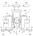
- FIG. 4 is an operating principle diagram of the redox flow battery according to the first embodiment.
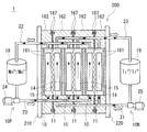
- FIG. 5 is a schematic configuration diagram of the redox flow battery according to the first embodiment.
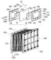
- FIG. 6 is a schematic configuration diagram of a cell stack provided in the redox flow battery according to the first embodiment.
- one of the purposes of the present disclosure is to provide an electrode that can easily achieve both improvement of battery reactivity and extension of life.
- Another object of the present disclosure is to provide a redox flow battery having excellent battery reactivity for a long period of time.
- one of the purposes of the present disclosure is to provide a method for manufacturing an electrode capable of manufacturing an electrode that can easily achieve both improvement in battery reactivity and long life.
- One of the purposes of the present disclosure is to provide a method for regenerating an electrode that can restore the performance of the electrode.
- Electrodes according to the present disclosure can easily achieve both improved battery reactivity and longer life.
- the redox flow battery according to the present disclosure has excellent battery reactivity for a long period of time.
- the electrode manufacturing method according to the present disclosure can manufacture an electrode that can easily achieve both improvement in battery reactivity and long life.
- the electrode regeneration method according to the present disclosure can restore the performance of the electrode.
- the electrode according to one aspect of the present disclosure is It is an electrode of a redox flow battery that circulates an electrolytic solution. Porous medium and It has reactive particles that contribute to the battery reaction, The reactive particles are pressed against the porous body by the flow of the electrolytic solution without being fixed to the porous body.
- the above configuration makes it easy to achieve both improved battery responsiveness and longer life.
- the reason why the battery reactivity can be improved is that the surface area of the electrode, that is, the reaction area can be easily increased by having the reactive particles.
- the surface area of the electrode can be easily adjusted by changing the amount of reactive particles. Therefore, the output of the redox flow battery provided with this electrode can be easily changed.
- the reason why the life can be extended will be described in detail later, but even if the reactive particles deteriorate, new reactive particles before deterioration can be deposited on the surface of the porous body to restore the performance of the electrode. is there.
- the flow resistance of the electrolytic solution is unlikely to increase.
- the reactive particles themselves are not fixed to the porous body, the reactive particles group pressed against the surface of the porous body can move so as to reduce the flow resistance according to the flow of the electrolytic solution. Is.
- the reactive particles include those larger than the size of the pores of the porous body.
- the reactive particles larger than the pores of the porous body include those that are pressed against the opening edge of the pores of the porous body by the flow of the electrolytic solution without being fixed to the porous body. Can be mentioned.
- the reactive particles include those larger than the pore size of the porous body, so that the surface area of the electrode, that is, the reaction area can be easily increased, and the reactive particles can be placed on the surface of the porous body. Easy to deposit.
- the basis weight of the reactive particles is 100 g / m 2 or more and 1500 g / m 2 or less.
- An electrode having a grain size of reactive particles that is, an electrode having a weight of reactive particles per 1 m 2 of a porous body of 100 g / m 2 or more is excellent in battery reactivity because there are many reactive particles with respect to the porous body.
- An electrode having a basis weight of reactive particles of 1500 g / m 2 or less tends to suppress an increase in the flow resistance of the electrolytic solution because the amount of reactive particles with respect to the porous body is not excessively large.
- the size of the reactive particles is 1 ⁇ m or more and 100 ⁇ m or less.
- Reactive particles with a size of 1 ⁇ m or more are sufficiently large in size, so it is difficult to increase the flow resistance of the electrolytic solution. Reactive particles having a size of 100 ⁇ m or less are not excessively large in size, so that it is difficult to reduce the battery reactivity.
- the material of the reactive particles may contain one or more elements selected from the group consisting of C, Pt, Ru, Mo, W, Nb, and Ta.
- Reactive particles containing the above elements make it easy to construct electrodes with excellent battery reactivity.
- the porosity of the porous body is 50% or more and 90% or less.
- a porous body with a porosity of 50% or more has many pores. Therefore, the porous body makes it easy to construct an electrode having excellent flowability of the electrolytic solution.
- a porous body having a porosity of 90% or less does not have too many pores. Therefore, this porous body can construct an electrode having excellent conductivity. Therefore, the electrodes make it easy to construct an RF battery having excellent battery reactivity.
- the size of the pores of the porous body is 0.1 ⁇ m or more and 100 ⁇ m or less.
- a porous body with a pore size of 0.1 ⁇ m or more can easily suppress an increase in the flow resistance of the electrolytic solution.
- a porous material having a pore size of 100 ⁇ m or less easily captures reactive particles. Therefore, this porous body makes it easy to construct an electrode having excellent battery reactivity.
- the material of the porous body may include one kind of material selected from the group consisting of C, Ti, and a conductive polymer.
- a porous body containing the above materials makes it easy to construct an electrode having excellent battery reactivity.
- the redox flow battery according to one aspect of the present disclosure is Battery cell and The battery cell is provided with a circulation mechanism for circulating the electrolytic solution.
- the battery cell is a redox flow battery having a positive electrode, a negative electrode, and a diaphragm interposed between the positive electrode and the negative electrode.
- At least one of the positive electrode and the negative electrode Porous medium and It has reactive particles that are larger than the size of the pores of the porous body and contribute to the battery reaction. The reactive particles are pressed against the opening edge of the pores of the porous body by the flow of the electrolytic solution without being fixed to the porous body.
- the above configuration has excellent battery reactivity for a long period of time.
- the reason is that the above-mentioned electrode is provided, which makes it easy to achieve both improvement in battery reactivity and extension of life.
- the method for manufacturing an electrode according to one aspect of the present disclosure is as follows.
- the present invention includes a step of circulating an electrolytic solution in which reactive particles larger than the size of the pores of the porous body and contributing to the battery reaction are mixed with the porous body.
- the above configuration can produce the above-mentioned electrode having a porous body and reactive particles. This is because the electrolytic solution mixed with the reactive particles is circulated through the porous body, so that the reactive particles are pressed against the opening edge of the pores of the porous body by the flow of the electrolytic solution.
- the electrode regeneration method according to one aspect of the present disclosure is described.
- the step of measuring the cell resistance of the battery cell and A step of replenishing the reactive particles with the electrolytic solution based on the measurement result of the cell resistance is provided.
- the above configuration can restore the performance of the electrodes.
- the reason for this is as follows.
- an electrolytic solution supplemented with new reactive particles before deterioration is circulated through the porous body.
- the flow of this electrolyte allows new reactive particles to be pressed against the open edges of the pores of the porous body or deposited on the reactive particles on the surface of the porous body.
- the redox flow battery of the first embodiment will be described with reference to FIGS. 1 to 6.
- the redox flow battery may be referred to as RF battery 1.
- the RF battery 1 includes a battery cell 10 and a circulation mechanism for circulating an electrolytic solution in the battery cell 10.
- the battery cell 10 has a positive electrode 14, a negative electrode 15, and a diaphragm 11 interposed between the positive electrode 14 and the negative electrode 15.
- One of the features of the RF battery 1 of this embodiment is that at least one of the positive electrode 14 and the negative electrode 15 is composed of a specific electrode 100.
- the outline and basic configuration of the RF battery 1 will be described, and then each configuration of the RF battery 1 of the present embodiment will be described in detail.
- the RF battery 1 is typically connected between the power generation unit 510 and the load 530 via the AC / DC converter 500 and the substation equipment 520, and charges and stores the power generated by the power generation unit 510.
- the stored electric power is discharged and supplied to the load 530 (FIG. 4).
- the solid arrow extending from the substation equipment 520 of FIG. 4 toward the AC / DC converter 500 means charging.
- the dashed arrow extending from the AC / DC converter 500 in FIG. 4 toward the substation equipment 520 means a discharge.
- Examples of the power generation unit 510 include a solar power generation device, a wind power generation device, and other general power plants.
- Examples of the load 530 include electric power consumers.
- the RF battery 1 uses an electrolytic solution containing a metal ion whose valence changes due to redox as an active material as a positive electrode electrolytic solution and a negative electrode electrolytic solution. Charging / discharging of the RF battery 1 is performed by utilizing the difference between the redox potential of the ions contained in the positive electrode electrolytic solution and the redox potential of the ions contained in the negative electrode electrolytic solution.
- the solid line arrow in the battery cell 10 of FIG. 4 means charging, and the broken line arrow means discharging.
- the RF battery 1 is used, for example, for load leveling applications, applications such as instantaneous low compensation and emergency power sources, and applications for smoothing the output of natural energy such as solar power generation and wind power generation, which are being introduced in large quantities. ..
- the RF battery 1 includes a battery cell 10 separated into a positive electrode cell 12 and a negative electrode cell 13 by a diaphragm 11 that allows hydrogen ions to permeate.
- a positive electrode electrode 14 is built in the positive electrode cell 12, and the positive electrode electrolytic solution is circulated by the positive electrode circulation mechanism 10P.
- the positive electrode circulation mechanism 10P is provided in the middle of the positive electrode electrolyte tank 18 for storing the positive electrode electrolyte, the supply conduit 20 and the discharge conduit 22 for connecting the positive electrode cell 12 and the positive electrode electrolyte tank 18, and the supply conduit 20.
- the pump 24 is provided.
- the negative electrode cell 13 has a built-in negative electrode electrode 15, and the negative electrode electrolytic solution is circulated by the negative electrode circulation mechanism 10N.
- the negative electrode circulation mechanism 10N is provided in the middle of the negative electrode electrolyte tank 19 for storing the negative electrode electrolyte, the supply conduit 21 and the discharge conduit 23 for connecting the negative electrode cell 13 and the negative electrode electrolyte tank 19, and the supply conduit 21.
- the pump 25 is provided.
- the positive electrode electrolyte and the negative electrode electrolyte are circulated from the positive electrode electrolyte tank 18 and the negative electrode electrolyte tank 19 through the supply conduit 20 and the supply conduit 21 by the pump 24 and the pump 25 to the positive electrode cell 12 and the positive electrode cell 12. It is supplied to the negative electrode cell 13. Then, the positive electrode electrolytic solution and the negative electrode electrolytic solution flow from the positive electrode cell 12 and the negative electrode cell 13 through the discharge conduit 22 and the discharge conduit 23 and are discharged to the positive electrode electrolyte tank 18 and the negative electrode electrolyte tank 19, so that the positive electrode cell 12 And is circulated in the negative electrode cell 13. During standby without charging / discharging, the pump 24 and the pump 25 are stopped, and the positive electrode electrolytic solution and the negative electrode electrolytic solution are not circulated.
- the electrode 100 of this embodiment constitutes at least one of the positive electrode 14 and the negative electrode 15 (FIGS. 4 to 6).
- the electrode 100 has a porous body 110 and reactive particles 120 that contribute to the battery reaction (FIGS. 1 to 3).
- the reactive particles 120 are pressed against the opening edge 112 of the pores 111 of the porous body 110 by the flow of the electrolytic solution.
- the porous body 110 retains the reactive particles 120 (FIG. 2). Although the porous body 110 depends on the material, the porous body 110 itself may have a function of contributing to the battery reaction. Contribution to the battery reaction includes not only the case where the porous body 110 itself functions as an electrode, but also the case where the porous body 110 itself functions as a catalyst for promoting the reaction regardless of the reaction system.
- the material of the porous body 110 is preferably one having conductivity.
- the material of the porous body 110 is, for example, C (carbon), Ti (titanium), Ru (ruthenium), Ir (iridium), W (tungsten), Pt (platinum), Au (gold), Pd (palladium), It may include one material selected from the group consisting of Mn (manganese) and a conductive polymer.
- the porous body 110 containing these materials makes it easy to construct the electrode 100 having excellent battery reactivity.
- the porous body 110 may be composed of the above-mentioned single element, or may be composed of a compound containing the above-mentioned element, specifically, an oxide.
- the porous body 110 may contain elements other than the above materials.
- porous body 110 examples include graphite, vitreous carbon, conductive diamond, conductive diamond-like carbon (DLC), non-woven fabric made of carbon fiber, woven fabric made of carbon fiber, non-woven fabric made of cellulose, and woven cloth made of cellulose. It may be composed of carbon paper made of carbon fiber and a conductive auxiliary agent, dimensionally stable electrode (DSE), and the like.
- the material of the porous body 110 is determined by X-ray diffraction (XRD). Specifically, it is obtained by using Empyrean manufactured by Malvern Panasonic.
- the porosity of the porous body 110 is preferably 50% or more and 90% or less.
- the porous body 110 having a porosity of 50% or more has many pores 111. Therefore, the porous body 110 makes it easy to construct the electrode 100 having excellent flowability of the electrolytic solution.
- the porous body 110 having a porosity of 90% or less does not have too many pores 111. Therefore, the porous body 110 can construct the electrode 100 having excellent conductivity. Therefore, the electrode 100 makes it easy to construct the RF battery 1 having excellent battery reactivity.
- the porosity of the porous body 110 is further preferably 60% or more and 80% or less, and particularly preferably 70% or more and 80% or less.
- the porosity of the porous body 110 refers to the porosity of the battery cell 10 or the compressed state after assembling a laminated body called sub-stack 200s, which will be described later with reference to the lower figure of FIG.
- the size of the pores 111 of the porous body 110 is preferably 0.1 ⁇ m or more and 100 ⁇ m or less.
- the porous body 110 having the pores 111 having a size of 0.1 ⁇ m or more makes it easy to construct the electrode 100 having excellent flowability of the electrolytic solution.
- the porous body 110 having pores 111 having a size of 100 ⁇ m or less easily captures the reactive particles 120. Therefore, the porous body 110 makes it easy to construct an electrode 100 having excellent battery reactivity.
- the size of the pores 111 of the porous body 110 is further preferably 1 ⁇ m or more, preferably 5 ⁇ m or more and 50 ⁇ m or less, and particularly preferably 10 ⁇ m or more and 30 ⁇ m or less.
- the size of the pores 111 of the porous body 110 refers to the size of the pores in the compressed state after assembling the battery cell 10 or the laminated body.
- the size of the pores 111 of the porous body 110 is determined as follows by an X-ray CT (Computed Tomography) and a mercury injection method on CAE (Computer Aided Engineering).
- a CT image is taken as a three-dimensional image in a state where the porous body 110 is compressed using a compression jig. This compression is performed so as to correspond to the compressed state after assembling the battery cell 10 or the laminated body.
- Xradia 520 Versa manufactured by Carl Zeiss Co., Ltd. can be used to take CT images.
- the distribution of pores in the CT image can be obtained.
- D50 is the size of the pores 111 of the porous body 110.
- the thickness of the porous body 110 is preferably 0.20 mm or more and 1.00 mm or less, for example.
- the porous body 110 having a thickness of 0.20 mm or more can increase the reaction field for performing the battery reaction. Since the porous body 110 having a thickness of 1.00 mm or less is not excessively thick, the RF battery 1 can be made thin.
- the thickness of the porous body 110 is further preferably 0.30 mm or more and 1.00 mm or less, and particularly preferably 0.40 mm or more and 0.70 mm or less.
- the thickness of the porous body 110 refers to the thickness in the uncompressed state before assembling the battery cell 10 or the laminated body.
- the thickness of the porous body 110 is an average value of the thicknesses of five or more places.
- the thickness of the compressed porous body 110 after assembling the battery cell 10 or the laminated body is preferably 0.20 mm or more and 0.60 mm or less, for example.
- the reactive particles 120 contribute to the battery reaction. As described above, contributing to the battery reaction includes not only the case where the reactive particle 120 itself functions as an electrode, but also the case where the reactive particle 120 itself functions as a catalyst for promoting the reaction regardless of the reaction system. .. It should be noted that at least one of the porous body 110 and the reactive particles 120 functions as an electrode. That is, it can be mentioned that at least one of the materials of the porous body 110 and the reactive particles 120 has conductivity.
- the reactive particles 120 are pressed against the porous body 110 by the flow of the electrolytic solution without being fixed to the porous body 110. Some of the reactive particles 120 are pressed against the opening edge 112 of the pores 111 of the porous body 110. That is, the reactive particles 120 are prevented from falling off from the porous body 110 due to the pressure due to the flow of the electrolytic solution. When the flow of the electrolytic solution is stopped, the reactive particles 120 are separated from the porous body 110. That is, the term "fixation" as used herein means that the reactive particles 120 are prevented from being separated from the porous body 110 even if the flow of the electrolytic solution is stopped. Since the reactive particles 120 are not fixed to the porous body 110, it is unlikely that the flow resistance of the electrolytic solution will increase. The reason is that the reactive particles 120 group pressed against the surface of the porous body 110 can move so as to reduce the flow resistance according to the flow of the electrolytic solution.
- the reactive particles 120 may be composed of only the substrate 121 (FIG. 2), or may be composed of the substrate 121 and the fine particles 122 adhering to the surface of the substrate 121 (FIG. 3).
- the substrate 121 is a large particle that occupies most of the reactive particles 120.
- the fine particles 122 are smaller than the base 121 and are a plurality of particles attached to the surface of the base 121.
- one of the substrate 121 and the fine particles 122 may function as a catalyst and the other may function as an electrode, or the substrate 121 and the fine particles 122 may function. Both may function as catalysts or electrodes.
- the fine particles 122 are adhered to the surface of the substrate 121 by depositing the constituent material of the substrate 121 in a molten state on the surface of the substrate 121 in a protruding shape, or are adhered to the surface of the substrate 121 by sputtering.
- the material of the reactive particles 120 contains one or more elements selected from the group consisting of C, Pt, Ru, Ti, Ir, Mo (molybdenum), W, Nb (niobium), and Ta (tantalum). Is preferable.
- the reactive particles 120 containing the above elements make it easy to construct an electrode 100 having excellent battery reactivity.
- the reactive particle 120 may be composed of the above-mentioned single element, or may be composed of a compound containing the above-mentioned element, specifically, an oxide. Examples of the oxide include one kind of oxide selected from the group consisting of Nb 2 O 5 , WO 3 , TiO 2 , RuO 2 , IrO 2 , and MnO 2 .
- the material of the reactive particles 120 refers to the material of the substrate 121 when the reactive particles 120 are composed of only the substrate 121, and when the reactive particles 120 are composed of the substrate 121 and the fine particles 122, Refers to each material of the base 121 and the fine particles 122.
- the materials of the base 121 and the fine particles 122 may be the same material or different materials from each other.
- the material of the reactive particles 120 is determined by XRD using the same apparatus as the porous body 110.
- the shape of the reactive particles 120 may be a kind of shape selected from the group consisting of spherical, ellipsoidal, scaly, needle-like, polygonal columnar, columnar, and elliptical columnar.
- the ellipsoidal shape includes a long spherical shape and an oblate spherical shape.
- Spherical, “elliptical”, “scaly”, “needle”, “polygonal column”, “cylindrical”, and “elliptical column” are geometrically spherical, ellipsoidal, and scaly.
- the shape of the reactive particles 120 means the shape of the substrate 121 when the reactive particles 120 are composed of only the substrate 121, and when the reactive particles 120 are composed of the substrate 121 and the fine particles 122, Refers to the respective shapes of the substrate 121 and the fine particles 122.
- the shapes of the base 121 and the fine particles 122 may be the same as each other or may be different from each other.
- the reactive particles 120 preferably include particles larger than the size of the pores 111 of the porous body 110.
- the reactive particles 120 satisfying this magnitude relationship are pressed against the porous body 110, particularly the opening edge 112 of the pores 111 of the porous body 110 by the flow of the electrolytic solution.
- the size of the reactive particles 120 is preferably 1 ⁇ m or more and 100 ⁇ m or less. Since the reactive particles 120 having a size of 1 ⁇ m or more are sufficiently large in size, it is difficult to increase the flow resistance of the electrolytic solution. Since the reactive particles 120 having a size of 100 ⁇ m or less are not excessively large in size, it is difficult to reduce the battery reactivity. In particular, it is preferable that the size of the reactive particles 120 larger than the size of the pores 111 of the porous body 110 satisfies the above range.
- the size of the reactive particles 120 means the size of the substrate 121 when the reactive particles 120 are composed of only the substrate 121, and when the reactive particles 120 are composed of the substrate 121 and the fine particles 122. , Refers to the overall size.
- the size of the reactive particles 120 is D50 measured by laser diffraction / scattering type particle size distribution measurement.
- the D50 refers to a particle size corresponding to 50% of the mass-based cumulative distribution curve.
- the above D50 is obtained by using Microtrack MT3300EXII manufactured by Microtrack Bell.
- the reactive particles 120 are separated from the porous body 110 by stopping the flow of the electrolytic solution or regurgitating the flow of the electrolytic solution. By recovering all the separated reactive particles 120, the above D50 of all the reactive particles 120 can be obtained. By separating only the reactive particles 120 larger than the size of the pores 111 of the porous body 110 from all the separated reactive particles 120, the reactive particles larger than the size of the pores 111 of the porous body 110 are separated. A D50 of 120
- the basis weight of the reactive particles 120 that is, the weight of the reactive particles 120 per 1 m 2 of the porous body 110 is preferably 100 g / m 2 or more and 1500 g / m 2 or less.
- the electrode 100 having a basis weight of the reactive particles 120 having a basis weight of 100 g / m 2 or more is excellent in battery reactivity because there are many reactive particles 120 with respect to the porous body 110.
- the reaction area of the electrode 100 can be easily adjusted by changing the basis weight. Therefore, the output of the RF battery 1 can be easily changed.
- the electrode 100 having a basis weight of the reactive particles 120 having a basis weight of 1500 g / m 2 or less does not have an excessively large amount of the reactive particles 120 with respect to the porous body 110, it is easy to suppress an increase in the flow resistance of the electrolytic solution.
- the basis weight of the reactive particles 120 is more preferably 100 g / m 2 or more and 500 g / m 2 or less, and particularly preferably 150 g / m 2 or more and 500 g / m 2 or less.
- the basis weight of the reactive particles 120 larger than the size of the pores 111 of the porous body 110 satisfies the above range.
- the basis weight of the reactive particles 120 is obtained by dividing the total weight of the reactive particles 120 by the total area of the porous body 110.
- the total weight of the reactive particles 120 can be measured by collecting all the reactive particles 120 separated from the porous body 110 as described above.
- the amount of the reactive particles 120 larger than the size of the pores 111 of the porous body 110 is the total weight of the reactive particles 120 larger than the size of the pores 111 of the porous body 110, and the total area of the porous body 110. It is calculated by dividing by.
- the total weight of the reactive particles 120 larger than the size of the pores 111 of the porous body 110 is larger than the size of the pores 111 of the porous body 110 from all the reactive particles 120 separated as described above. It can be measured by separating only the sex particles 120.
- the battery cell 10 is usually formed inside a structure called a cell stack 200, as shown in FIGS. 5 and 6 below.
- the cell stack 200 is configured by sandwiching a laminate called a sub-stack 200s between two end plates 220 from both sides thereof and tightening both end plates 220 by a tightening mechanism 230. ing.
- the lower figure of FIG. 6 illustrates a form including a plurality of sub-stacks 200s.
- a plurality of cell frames 16, positive electrode 14, diaphragm 11, and negative electrode 15 are laminated in this order.
- the sub-stack 200s has supply / discharge plates 210 arranged at both ends of the laminated body.
- the cell frame 16 includes a bipolar plate 161 and a frame body 162 that surrounds the outer peripheral edge portion thereof, and has a recess 160 on which the positive electrode electrode 14 or the negative electrode electrode 15 is arranged on the surface of the bipolar plate 161 and the inner peripheral surface of the frame body 162.
- One battery cell 10 is formed between the bipolar plates 161 of the adjacent cell frames 16, and the positive electrode 14 and the negative electrode 15 of the adjacent battery cells 10 are arranged on the front and back sides of the bipolar plate 161. 12 and the negative electrode cell 13 are arranged.
- a recess may be formed on the surface of the bipolar plate 161 to facilitate the flow of the electrolytic solution.
- the shape of the recess can be appropriately selected, and examples thereof include a known facing comb-teeth shape.
- the cell frame 16 includes an intermediate cell frame arranged between the adjacent battery cells 10 (FIGS. 4 to 6) of the laminated body and end cell frames arranged at both ends of the laminated body.
- the positive electrode 14 of one battery cell 10 and the negative electrode 15 of the other battery cell 10 are in contact with the front and back surfaces of the bipolar plate 161
- the end cell frame is the battery cell 10 on one surface of the bipolar plate 161.
- the configurations of the front and back surfaces of the cell frame 16, that is, the positive electrode side surface and the negative electrode side surface, are the same for both the intermediate cell frame and the end cell frame.
- the frame body 162 supports the bipolar plate 161 and forms an area to be the battery cell 10 inside.
- the shape of the frame body 162 is a rectangular frame shape, and the opening shape of the recess 160 is a rectangular shape.
- the frame body 162 includes a liquid supply side piece and a drainage side piece facing the liquid supply side piece.
- the liquid supply side piece is on the lower side in the vertical direction.
- the drainage side piece is located on the upper side in the vertical direction.
- the liquid supply side piece has a liquid supply manifold 163, 164 and a liquid supply slit 163s, 164s for supplying an electrolytic solution to the inside of the battery cell 10.
- the drainage side piece has a drainage manifold 165, 166 and drainage slits 165s, 166s for draining the electrolytic solution to the outside of the battery cell 10.
- the flow of the electrolytic solution is from the lower side in the vertical direction to the upper side in the vertical direction of the frame body 162.
- the liquid supply side piece may be formed with a liquid supply rectifying portion formed on the inner edge thereof and diffusing the electrolytic solution flowing through the liquid supply slits 163s and 164s along the inner edge thereof.
- the illustration of the liquid supply rectifying unit is omitted.
- the drainage side piece may be formed with a drainage rectifying portion formed on the inner edge thereof and collecting the electrolytic solution flowing through the positive electrode 14 or the negative electrode 15 and circulating the electrolytic solution through the drainage slits 165s and 166s.
- the illustration of the drainage rectifying unit is omitted.
- each electrode electrolyte in the cell frame 16 is as follows.
- the positive electrode electrolytic solution flows from the liquid supply manifold 163 through the liquid supply slit 163s formed in the liquid supply side piece on one surface side of the frame body 162 and is supplied to the positive electrode electrode 14.
- the one side of the frame 162 is the front side of the paper in FIG.
- the positive electrode electrolytic solution flows from the lower side to the upper side of the positive electrode electrode 14 and flows through the drainage slit 165s formed in the drainage side piece to flow through the drainage manifold. It is discharged to 165.
- the supply and discharge of the negative electrode electrolyte is the same as that of the positive electrode electrolyte except that it is performed by the liquid supply manifold 164, the liquid supply slit 164s, the drainage slit 166s, and the drainage manifold 166 on the other side of the frame 162. is there.
- the other side of the frame 162 is the back side of the paper in FIG.
- annular seal member 167 such as an O-ring or flat packing is arranged in an annular seal groove.
- the seal member 167 suppresses leakage of the electrolytic solution from the battery cell 10.
- the positive electrode electrolytic solution and the negative electrode electrolytic solution are circulated and supplied to the positive electrode electrode 14 and the negative electrode electrode 15 by the above-mentioned positive electrode circulation mechanism 10P and negative electrode circulation mechanism 10N.
- This circulation charging and discharging are performed according to the valence change reaction of the active material ions of the positive electrode electrolytic solution and the negative electrode electrolytic solution.
- the positive electrode 14 is oxidatively deteriorated due to a side reaction accompanying charge and discharge, which tends to cause an increase in cell resistance. Therefore, when the electrode 100 is used for the positive electrode 14, the cell resistance can be effectively reduced.
- the active material of the positive electrode electrolytic solution may contain one or more selected from the group consisting of manganese ion, vanadium ion, iron ion, polyacid, quinone derivative, and amine.
- the active material of the negative electrode electrolytic solution may contain one or more selected from the group consisting of titanium ion, vanadium ion, chromium ion, polyacid, quinone derivative, and amine. 4 and 5 show manganese (Mn) ions as the ions contained in the positive electrode electrolytic solution, and titanium (Ti) ions as the ions contained in the negative electrode electrolytic solution.
- the positive electrode electrode 14 In the case of an Mn—Ti-based electrolytic solution containing Mn ions as the positive electrode active material and Ti ions as the negative electrode active material, the positive electrode electrode 14 is likely to be oxidatively deteriorated. Therefore, in the case of the Mn—Ti-based electrolytic solution, if the electrode 100 is used for the positive electrode electrode 14, the cell resistance can be effectively reduced.
- the concentration of the positive electrode active material and the concentration of the negative electrode active material can be appropriately selected.
- at least one of the concentration of the positive electrode active material and the concentration of the negative electrode active material is 0.3 mol / L or more and 5 mol / L or less.
- the concentration is 0.3 mol / L or more, it can have a sufficient energy density for a large-capacity storage battery, for example, about 10 kWh / m 3 .
- the higher the concentration the higher the energy density.
- the above-mentioned concentration is 0.5 mol / L or more and 1.0 mol / L or more, and particularly 1.2 mol / L or more and 1.5 mol / L or more.
- the solubility in a solvent can be easily increased. It is easy to use the above concentration of 2 mol / L or less.
- An electrolytic solution satisfying this concentration is excellent in manufacturability.
- Examples of the solvent of the electrolytic solution include an aqueous solution containing one or more acids or acid salts selected from the group consisting of sulfuric acid, phosphoric acid, nitric acid, and hydrochloric acid.
- the RF battery 1 of this embodiment has excellent battery reactivity for a long period of time. This is because the RF battery 1 includes an electrode 100 that can easily achieve both an improvement in battery reactivity and a long life.
- the reason why the battery reactivity can be improved is that the surface area of the electrode 100 can be increased by having the reactive particles 120 in the electrode 100.
- the reason why the life can be extended will be described in detail later, but even if the reactive particles 120 deteriorate, new reactive particles 120 before deterioration can be deposited on the surface of the porous body 110, so that the performance of the electrode 100 is restored. Because it is made to. Further, some reactive particles 120 may invade the inside of the porous body 110. The performance of the electrode 100 can also be restored by the new reactive particles 120 inside the porous body 110.
- the above-mentioned electrode 100 can be manufactured by the method for manufacturing an electrode of the present embodiment including the following steps S1 and S2.
- Step S1 the battery cell 10 or the cell stack 200 of the RF battery 1 is prepared.
- the battery cell 10 or cell stack 200 is the same as the battery cell 10 or cell stack 200 described above.
- the porous body 110 is housed between the bipolar plate 161 and the diaphragm 11.
- the porous body 110 is the same as the porous body 110 in the electrode 100 described above.
- Step S2 the electrolytic solution is circulated through the porous body 110.
- Reactive particles 120 that contribute to the battery reaction are mixed in this electrolytic solution.
- the reactive particles 120 are the same as the reactive particles 120 in the electrode 100 of the first embodiment described above.
- the mixing of the reactive particles 120 may be performed in advance using an appropriate container outside the positive electrode electrolyte tank 18, or the reactive particles 120 are charged into the positive electrode electrolyte tank 18 for storing the electrolyte. You may go in the tank.
- the above-mentioned positive electrode circulation mechanism 10P can be used for the circulation of the electrolytic solution.
- the distribution route of the electrolytic solution is as described above.
- the electrolytic solution is supplied from the positive electrode electrolytic solution tank 18 through the supply conduit 20 to the porous body 110 from the liquid supply manifold 163 and the liquid supply slit 163s of the frame body 162 of the cell frame 16.
- the reactive particles 120 contained in the electrolytic solution are pressed against the opening edge 112 of the pores 111 of the porous body 110 by the flow of the electrolytic solution.
- the electrode 100 is manufactured by pressing the reactive particles 120.
- some reactive particles 120 may invade the inside of the porous body 110.
- the above-mentioned negative electrode circulation mechanism 10N can be used for the circulation of the electrolytic solution.
- the distribution route of the electrolytic solution is as described above. That is, the electrolytic solution is supplied from the negative electrode electrolytic solution tank 19 through the supply conduit 21 to the porous body 110 from the liquid supply manifold 164 and the liquid supply slit 164s of the frame body 162 of the cell frame 16.
- the electrode manufacturing method of this embodiment can manufacture an electrode 100 that can easily achieve both improvement in battery reactivity and long life. This is because the electrolytic solution mixed with the reactive particles 120 is circulated through the porous body 110, so that the reactive particles 120 are pressed against the opening edge 112 of the pores 111 of the porous body 110. Therefore, the reactive particles 120 can be deposited on the surface of the porous body 110, or a part of the reactive particles 120 can be invaded inside the porous body 110.
- the above-mentioned electrode 100 can be regenerated, that is, its performance can be recovered by the method of regenerating the electrode including the following steps S11 to S13.
- Step S11 the RF battery 1 is charged and discharged.
- the RF battery 1 is the same as the RF battery 1 described above. That is, the electrode 100 of the RF battery 1 is the electrode 100 having the above-mentioned porous body 110 and the reactive particles 120. Charging / discharging of the RF battery 1 is performed by circulating an electrolytic solution in the battery cell 10. As the circulation of the electrolytic solution, the above-mentioned circulation mechanism 10P for the positive electrode and the circulation mechanism 10N for the negative electrode can be used.
- Step S12 the cell resistance of the battery cell 10 is measured.
- the cell resistance is obtained from the open circuit voltage measured by the monitor cell and the charge / discharge current measured by the ammeter provided in the AC / DC converter 500.
- the illustration of the monitor cell is omitted.
- the monitor cell has the same configuration as the battery cell 10, but is a battery cell to which the AC / DC converter 500 is not connected and does not contribute to charging / discharging.
- Step S13 the reactive particles 120 are replenished with the electrolytic solution based on the measured cell resistance of the battery cell 10.
- the replenishment of the reactive particles 120 is performed when the cell resistance of the battery cell 10 exceeds a preset threshold value.
- the replenishment amount of the reactive particles 120 is determined from, for example, the result of operating the test battery in advance to determine how much the reactive particles 120 should be replenished to reduce the cell resistance.
- the reactive particles 120 to be replenished contribute to the battery reaction and are the same as the reactive particles 120 in the electrode 100 described above.
- the positive electrode electrolyte tank 18 can be mentioned as a replenishment point for the reactive particles 120.
- the replenishment location of the reactive particles 120 may be downstream of the pump 24 in the supply conduit 20. That is, the replenishment location of the reactive particles 120 may be between the pump 24 and the battery cell 10.
- the reactive particles 120 may be replenished from the opening of the positive electrode electrolyte tank 18 by opening the top plate of the positive electrode electrolyte tank 18, or a replenishment port may be separately provided downstream of the pump 24 in the supply conduit 20. , You may go from the replenishment port.
- the replenishment port is closed when the reactive particles 120 are not replenished.
- the replenishment location of the reactive particles 120 may be the negative electrode electrolyte tank 19.
- the replenishment location of the reactive particles 120 may be downstream of the pump 25 in the supply conduit 21. That is, the replenishment location of the reactive particles 120 may be between the pump 25 and the battery cell 10.
- the reactive particles 120 may be replenished by opening the top plate of the negative electrode electrolyte tank 19 and opening the negative electrode electrolyte tank 19, or a replenishment port is separately provided downstream of the pump 25 in the supply conduit 21. , You may go from the replenishment port.
- the timing of replenishment of the reactive particles 120 is preferably after the pump 24 is stopped and the flow of the electrolytic solution is stopped. After the replenishment is completed, the RF battery 1 drives the pump 24 to circulate the electrolytic solution. By this circulation, the reactive particles 120 contained in the electrolytic solution are pressed against the opening edge 112 of the pores 111 of the porous body 110, or are deposited on the reactive particles 120 on the surface of the porous body 110. Further, some reactive particles 120 may invade the inside of the porous body 110.
- the timing of replenishing the reactive particles 120 is preferably after the pump 25 is stopped and the flow of the electrolytic solution is stopped. After the replenishment is completed, the RF battery 1 drives the pump 25 to circulate the electrolytic solution.
- the electrode regeneration method of this embodiment can restore the performance of the electrode 100.
- the reason for this is as follows.
- an electrolytic solution supplemented with new reactive particles 120 before deterioration is circulated through the porous body 110. Due to the flow of this electrolytic solution, new reactive particles 120 are pressed against the opening edge 112 of the pores 111 of the porous body 110, or are deposited on the reactive particles 120 on the surface of the porous body 110, or are porous. It can be invaded inside the body 110.
Landscapes
- Chemical & Material Sciences (AREA)
- Chemical Kinetics & Catalysis (AREA)
- Electrochemistry (AREA)
- General Chemical & Material Sciences (AREA)
- Engineering & Computer Science (AREA)
- Manufacturing & Machinery (AREA)
- Life Sciences & Earth Sciences (AREA)
- Sustainable Development (AREA)
- Sustainable Energy (AREA)
- Materials Engineering (AREA)
- Composite Materials (AREA)
- Fuel Cell (AREA)
- Inert Electrodes (AREA)
Abstract
電解液を循環させるレドックスフロー電池の電極であって、多孔質体と、電池反応に寄与する反応性粒子とを有し、前記反応性粒子は、前記多孔質体に固定されることなく前記電解液の流通によって前記多孔質体に押し付けられている、電極。
Description
本開示は、電極、レドックスフロー電池、電極の製造方法、及び電極の再生方法に関する。
本出願は、2019年3月12日付の日本国出願の特願2019-045261に基づく優先権を主張し、前記日本国出願に記載された全ての記載内容を援用するものである。
本出願は、2019年3月12日付の日本国出願の特願2019-045261に基づく優先権を主張し、前記日本国出願に記載された全ての記載内容を援用するものである。
特許文献1のレドックスフロー電池は、電池セルの電極に、炭素繊維からなる織布や不織布、即ちカーボンクロスやカーボンフェルトなどが用いられている。
本開示に係る電極は、
電解液を循環させるレドックスフロー電池の電極であって、
多孔質体と、
電池反応に寄与する反応性粒子とを有し、
前記反応性粒子は、前記多孔質体に固定されることなく前記電解液の流通によって前記多孔質体に押し付けられている。
電解液を循環させるレドックスフロー電池の電極であって、
多孔質体と、
電池反応に寄与する反応性粒子とを有し、
前記反応性粒子は、前記多孔質体に固定されることなく前記電解液の流通によって前記多孔質体に押し付けられている。
本開示に係るレドックスフロー電池は、
電池セルと、
前記電池セルに電解液を循環する循環機構とを備え、
前記電池セルは、正極電極と、負極電極と、前記正極電極と前記負極電極との間に介在される隔膜とを有するレドックスフロー電池であって、
前記正極電極及び前記負極電極の少なくとも一方は、
多孔質体と、
電池反応に寄与する反応性粒子とを有し、
前記反応性粒子は、前記多孔質体に固定されることなく前記電解液の流通によって前記多孔質体に押し付けられている。
電池セルと、
前記電池セルに電解液を循環する循環機構とを備え、
前記電池セルは、正極電極と、負極電極と、前記正極電極と前記負極電極との間に介在される隔膜とを有するレドックスフロー電池であって、
前記正極電極及び前記負極電極の少なくとも一方は、
多孔質体と、
電池反応に寄与する反応性粒子とを有し、
前記反応性粒子は、前記多孔質体に固定されることなく前記電解液の流通によって前記多孔質体に押し付けられている。
本開示に係る電極の製造方法は、
多孔質体が収納されたレドックスフロー電池の電池セルを準備する工程と、
電池反応に寄与する反応性粒子が混合された電解液を前記多孔質体に対して流通させることで、前記反応性粒子を前記多孔質体に固定されることなく押し付ける工程とを備える。
多孔質体が収納されたレドックスフロー電池の電池セルを準備する工程と、
電池反応に寄与する反応性粒子が混合された電解液を前記多孔質体に対して流通させることで、前記反応性粒子を前記多孔質体に固定されることなく押し付ける工程とを備える。
本開示に係る電極の再生方法は、
本開示に係る電極を有する電池セル、又は本開示に係るレドックスフロー電池に備わる電池セルに電解液を循環させて充放電を行う工程と、
前記電池セルのセル抵抗を測定する工程と、
前記セル抵抗の測定結果に基づき、前記反応性粒子を前記電解液に補充する工程とを備える。
本開示に係る電極を有する電池セル、又は本開示に係るレドックスフロー電池に備わる電池セルに電解液を循環させて充放電を行う工程と、
前記電池セルのセル抵抗を測定する工程と、
前記セル抵抗の測定結果に基づき、前記反応性粒子を前記電解液に補充する工程とを備える。
[本開示が解決しようとする課題]
電極の電池反応性を向上するには、一般的に電極の表面積を大きくすることが考えられる。しかし、電極の表面積が大きいほど、電極の劣化速度が早くなる。即ち、電極の寿命が短くなる。
電極の電池反応性を向上するには、一般的に電極の表面積を大きくすることが考えられる。しかし、電極の表面積が大きいほど、電極の劣化速度が早くなる。即ち、電極の寿命が短くなる。
そこで、本開示は、電池反応性の向上と長寿命化とを両立し易い電極を提供することを目的の一つとする。
また、本開示は、長期にわたって電池反応性に優れるレドックスフロー電池を提供することを目的の一つとする。
更に、本開示は、電池反応性の向上と長寿命化とを両立し易い電極を製造できる電極の製造方法を提供することを目的の一つとする。
そして、本開示は、電極の性能を回復できる電極の再生方法を提供することを目的の一つとする。
[本開示の効果]
本開示に係る電極は、電池反応性の向上と長寿命化とを両立し易い。
本開示に係る電極は、電池反応性の向上と長寿命化とを両立し易い。
本開示に係るレドックスフロー電池は、長期にわたって電池反応性に優れる。
本開示に係る電極の製造方法は、電池反応性の向上と長寿命化とを両立し易い電極を製造できる。
本開示に係る電極の再生方法は、電極の性能を回復できる。
《本開示の実施形態の説明》
最初に本開示の実施態様を列記して説明する。
最初に本開示の実施態様を列記して説明する。
(1)本開示の一態様に係る電極は、
電解液を循環させるレドックスフロー電池の電極であって、
多孔質体と、
電池反応に寄与する反応性粒子とを有し、
前記反応性粒子は、前記多孔質体に固定されることなく前記電解液の流通によって前記多孔質体に押し付けられている。
電解液を循環させるレドックスフロー電池の電極であって、
多孔質体と、
電池反応に寄与する反応性粒子とを有し、
前記反応性粒子は、前記多孔質体に固定されることなく前記電解液の流通によって前記多孔質体に押し付けられている。
上記の構成は、電池反応性の向上と長寿命化とを両立し易い。電池反応性を向上できる理由は、反応性粒子を有することで、電極の表面積、即ち反応面積を大きくし易いからである。電極の表面積は、反応性粒子の量を変えることで容易に調整できる。そのため、この電極を備えるレドックスフロー電池の出力を容易に変えることができる。長寿命化できる理由は、詳しくは後述するが、反応性粒子が劣化しても劣化前の新たな反応性粒子を多孔質体の表面に堆積させられて、電極の性能を回復させられるからである。
また、上記の構成は、電解液の流通抵抗の上昇が生じ難い。その理由は、反応性粒子自体が多孔質体に固定されていないため、多孔質体の表面に押し付けられた反応性粒子群が電解液の流れに応じて流通抵抗が小さくなるように移動できるからである。
(2)上記電極の一形態として、
前記反応性粒子は、前記多孔質体の空孔の大きさよりも大きいものを含み、
前記多孔質体の空孔よりも大きな前記反応性粒子は、前記多孔質体に固定されることなく前記電解液の流通によって前記多孔質体の空孔の開口縁に押し付けられているものを含むことが挙げられる。
前記反応性粒子は、前記多孔質体の空孔の大きさよりも大きいものを含み、
前記多孔質体の空孔よりも大きな前記反応性粒子は、前記多孔質体に固定されることなく前記電解液の流通によって前記多孔質体の空孔の開口縁に押し付けられているものを含むことが挙げられる。
上記の構成は、反応性粒子が多孔質体の空孔の大きさよりも大きいものを含むことで、電極の表面積、即ち反応面積を大きくし易い上に、反応性粒子を多孔質体の表面に堆積させ易い。
(3)上記電極の一形態として、
前記反応性粒子の目付量は、100g/m2以上1500g/m2以下であることが挙げられる。
前記反応性粒子の目付量は、100g/m2以上1500g/m2以下であることが挙げられる。
反応粒子の目付量、即ち多孔質体の1m2当たりの反応性粒子の重量が100g/m2以上の電極は、多孔質体に対する反応性粒子が多いため、電池反応性に優れる。反応性粒子の目付量が1500g/m2以下の電極は、多孔質体に対する反応性粒子が過度に多すぎないため、電解液の流通抵抗の上昇を抑制し易い。
(4)上記電極の一形態として、
前記反応性粒子の大きさは、1μm以上100μm以下であることが挙げられる。
前記反応性粒子の大きさは、1μm以上100μm以下であることが挙げられる。
大きさが1μm以上の反応性粒子は、大きさが十分に大きいため、電解液の流通抵抗を上昇させ難い。大きさが100μm以下の反応性粒子は、大きさが過度に大きすぎないため、電池反応性を低下させ難い。
(5)上記電極の一形態として、
前記反応性粒子の材質は、C,Pt,Ru,Mo,W,Nb,及びTaからなる群より選択される1種以上の元素を含むことが挙げられる。
前記反応性粒子の材質は、C,Pt,Ru,Mo,W,Nb,及びTaからなる群より選択される1種以上の元素を含むことが挙げられる。
上記の元素を含む反応性粒子は、電池反応性に優れる電極を構築し易い。
(6)上記電極の一形態として、
前記多孔質体の空孔率は、50%以上90%以下であることが挙げられる。
前記多孔質体の空孔率は、50%以上90%以下であることが挙げられる。
空孔率が50%以上の多孔質体は、空孔が多い。そのため、多孔質体は、電解液の流通性に優れる電極を構築し易い。空孔率が90%以下の多孔質体は、空孔が多すぎない。そのため、この多孔質体は、導電性に優れる電極を構築できる。よって、電極は、電池反応性に優れるRF電池を構築し易い。
(7)上記電極の一形態として、
前記多孔質体の空孔の大きさは、0.1μm以上100μm以下であることが挙げられる。
前記多孔質体の空孔の大きさは、0.1μm以上100μm以下であることが挙げられる。
空孔の大きさが0.1μm以上の多孔質体は、電解液の流通抵抗の上昇を抑制し易い。空孔の大きさが100μm以下の多孔質体は、反応性粒子を捕捉し易い。そのため、この多孔質体は、電池反応性に優れる電極を構築し易い。
(8)上記電極の一形態として、
前記多孔質体の材質は、C,Ti,及び導電性ポリマからなる群より選択される1種の材質を含むことが挙げられる。
前記多孔質体の材質は、C,Ti,及び導電性ポリマからなる群より選択される1種の材質を含むことが挙げられる。
上記の材質を含む多孔質体は、電池反応性に優れる電極を構築し易い。
(9)本開示の一態様に係るレドックスフロー電池は、
電池セルと、
前記電池セルに電解液を循環する循環機構とを備え、
前記電池セルは、正極電極と、負極電極と、前記正極電極と前記負極電極との間に介在される隔膜とを有するレドックスフロー電池であって、
前記正極電極及び前記負極電極の少なくとも一方は、
多孔質体と、
前記多孔質体の空孔の大きさよりも大きくて、電池反応に寄与する反応性粒子とを有し、
前記反応性粒子は、前記多孔質体に固定されることなく前記電解液の流通によって前記多孔質体の空孔の開口縁に押し付けられている。
電池セルと、
前記電池セルに電解液を循環する循環機構とを備え、
前記電池セルは、正極電極と、負極電極と、前記正極電極と前記負極電極との間に介在される隔膜とを有するレドックスフロー電池であって、
前記正極電極及び前記負極電極の少なくとも一方は、
多孔質体と、
前記多孔質体の空孔の大きさよりも大きくて、電池反応に寄与する反応性粒子とを有し、
前記反応性粒子は、前記多孔質体に固定されることなく前記電解液の流通によって前記多孔質体の空孔の開口縁に押し付けられている。
上記の構成は、長期にわたって電池反応性に優れる。その理由は、電池反応性の向上と長寿命化とを両立し易い上述の電極を備えるからである。
(10)本開示の一態様に係る電極の製造方法は、
多孔質体が収納されたレドックスフロー電池の電池セルを準備する工程と、
前記多孔質体の空孔の大きさよりも大きくて電池反応に寄与する反応性粒子が混合された電解液を前記多孔質体に対して流通させる工程とを備える。
多孔質体が収納されたレドックスフロー電池の電池セルを準備する工程と、
前記多孔質体の空孔の大きさよりも大きくて電池反応に寄与する反応性粒子が混合された電解液を前記多孔質体に対して流通させる工程とを備える。
上記の構成は、多孔質体と反応性粒子とを有する上述の電極を製造できる。反応性粒子が混合された電解液を多孔質体に対して流通させることで、電解液の流通により反応性粒子を多孔質体の空孔の開口縁に押し付けられるからである。
(11)本開示の一態様に係る電極の再生方法は、
(1)から(8)のいずれか1つの電極を有する電池セル、又は(9)のレドックスフロー電池に備わる電池セルに電解液を循環させて充放電を行う工程と、
前記電池セルのセル抵抗を測定する工程と、
前記セル抵抗の測定結果に基づき、前記反応性粒子を前記電解液に補充する工程とを備える。
(1)から(8)のいずれか1つの電極を有する電池セル、又は(9)のレドックスフロー電池に備わる電池セルに電解液を循環させて充放電を行う工程と、
前記電池セルのセル抵抗を測定する工程と、
前記セル抵抗の測定結果に基づき、前記反応性粒子を前記電解液に補充する工程とを備える。
上記の構成は、電極の性能を回復できる。この理由は、次の通りである。電極の性能が低下した際、劣化前の新たな反応性粒子を補充した電解液を多孔質体に対して流通させる。この電解液の流通により新たな反応性粒子が、多孔質体の空孔の開口縁に押し付けられたり、多孔質体の表面における反応性粒子の上に堆積させられたりすることができる。
《本開示の実施形態の詳細》
本開示の実施形態の詳細を、以下に説明する。図中の同一符号は同一名称物を示す。
本開示の実施形態の詳細を、以下に説明する。図中の同一符号は同一名称物を示す。
《実施形態1》
〔レドックスフロー電池〕
図1から図6を参照して、実施形態1のレドックスフロー電池を説明する。以下、レドックスフロー電池をRF電池1と表記することがある。図4、図5に示すように、RF電池1は、電池セル10と電池セル10に電解液を循環する循環機構とを備える。電池セル10は、正極電極14と、負極電極15と、正極電極14と負極電極15との間に介在される隔膜11とを有する。本形態のRF電池1の特徴の一つは、正極電極14及び負極電極15の少なくとも一方が特定の電極100で構成されている点にある。以下、RF電池1の概要と基本構成を説明し、その後、本形態のRF電池1の各構成を詳細に説明する。
〔レドックスフロー電池〕
図1から図6を参照して、実施形態1のレドックスフロー電池を説明する。以下、レドックスフロー電池をRF電池1と表記することがある。図4、図5に示すように、RF電池1は、電池セル10と電池セル10に電解液を循環する循環機構とを備える。電池セル10は、正極電極14と、負極電極15と、正極電極14と負極電極15との間に介在される隔膜11とを有する。本形態のRF電池1の特徴の一つは、正極電極14及び負極電極15の少なくとも一方が特定の電極100で構成されている点にある。以下、RF電池1の概要と基本構成を説明し、その後、本形態のRF電池1の各構成を詳細に説明する。
[RF電池の概要]
RF電池1は、代表的には、交流/直流変換器500と変電設備520とを介して発電部510と負荷530との間に接続され、発電部510で発電した電力を充電して蓄え、蓄えた電力を放電して負荷530に供給する(図4)。図4の変電設備520から交流/直流変換器500に向かって伸びる実線矢印は充電を意味する。図4の交流/直流変換器500から変電設備520に向かって伸びる破線矢印は放電を意味する。発電部510としては、例えば、太陽光発電装置や風力発電装置、その他一般の発電所などが挙げられる。負荷530としては、例えば、電力の需要家などが挙げられる。RF電池1は、酸化還元により価数が変化する金属イオンを活物質として含有する電解液を正極電解液と負極電解液とに使用する。RF電池1の充放電は、正極電解液に含まれるイオンの酸化還元電位と負極電解液に含まれるイオンの酸化還元電位との差を利用して行われる。図4の電池セル10内における実線矢印は充電、破線矢印は放電を意味する。RF電池1は、例えば、負荷平準化用途、瞬低補償や非常用電源などの用途、大量導入が進められている太陽光発電や風力発電などの自然エネルギーの出力平滑化用途などに利用される。
RF電池1は、代表的には、交流/直流変換器500と変電設備520とを介して発電部510と負荷530との間に接続され、発電部510で発電した電力を充電して蓄え、蓄えた電力を放電して負荷530に供給する(図4)。図4の変電設備520から交流/直流変換器500に向かって伸びる実線矢印は充電を意味する。図4の交流/直流変換器500から変電設備520に向かって伸びる破線矢印は放電を意味する。発電部510としては、例えば、太陽光発電装置や風力発電装置、その他一般の発電所などが挙げられる。負荷530としては、例えば、電力の需要家などが挙げられる。RF電池1は、酸化還元により価数が変化する金属イオンを活物質として含有する電解液を正極電解液と負極電解液とに使用する。RF電池1の充放電は、正極電解液に含まれるイオンの酸化還元電位と負極電解液に含まれるイオンの酸化還元電位との差を利用して行われる。図4の電池セル10内における実線矢印は充電、破線矢印は放電を意味する。RF電池1は、例えば、負荷平準化用途、瞬低補償や非常用電源などの用途、大量導入が進められている太陽光発電や風力発電などの自然エネルギーの出力平滑化用途などに利用される。
[RF電池の基本構成]
RF電池1は、水素イオンを透過させる隔膜11で正極セル12と負極セル13とに分離された電池セル10を備える。正極セル12には、正極電極14が内蔵され、正極用循環機構10Pにより正極電解液が循環する。正極用循環機構10Pは、正極電解液を貯留する正極電解液タンク18と、正極セル12と正極電解液タンク18とを接続する供給導管20及び排出導管22と、供給導管20の途中に設けられたポンプ24とを備える。同様に、負極セル13には、負極電極15が内蔵され、負極用循環機構10Nにより負極電解液が循環する。負極用循環機構10Nは、負極電解液を貯留する負極電解液タンク19と、負極セル13と負極電解液タンク19とを接続する供給導管21及び排出導管23と、供給導管21の途中に設けられたポンプ25とを備える。
RF電池1は、水素イオンを透過させる隔膜11で正極セル12と負極セル13とに分離された電池セル10を備える。正極セル12には、正極電極14が内蔵され、正極用循環機構10Pにより正極電解液が循環する。正極用循環機構10Pは、正極電解液を貯留する正極電解液タンク18と、正極セル12と正極電解液タンク18とを接続する供給導管20及び排出導管22と、供給導管20の途中に設けられたポンプ24とを備える。同様に、負極セル13には、負極電極15が内蔵され、負極用循環機構10Nにより負極電解液が循環する。負極用循環機構10Nは、負極電解液を貯留する負極電解液タンク19と、負極セル13と負極電解液タンク19とを接続する供給導管21及び排出導管23と、供給導管21の途中に設けられたポンプ25とを備える。
充放電を行う運転時、ポンプ24及びポンプ25により、正極電解液及び負極電解液は、正極電解液タンク18及び負極電解液タンク19から供給導管20及び供給導管21を流通して正極セル12及び負極セル13に供給される。そして、正極電解液及び負極電解液は、正極セル12及び負極セル13から排出導管22及び排出導管23を流通して正極電解液タンク18及び負極電解液タンク19に排出されることで正極セル12及び負極セル13に循環される。充放電を行わない待機時、ポンプ24及びポンプ25が停止され、正極電解液及び負極電解液は循環されない。
[電極]
本形態の電極100は、上述したように正極電極14及び負極電極15(図4から図6)の少なくとも一方を構成する。この電極100は、多孔質体110と、電池反応に寄与する反応性粒子120とを有する(図1から図3)。この反応性粒子120は、電解液の流通によって多孔質体110の空孔111の開口縁112に押し付けられている。
本形態の電極100は、上述したように正極電極14及び負極電極15(図4から図6)の少なくとも一方を構成する。この電極100は、多孔質体110と、電池反応に寄与する反応性粒子120とを有する(図1から図3)。この反応性粒子120は、電解液の流通によって多孔質体110の空孔111の開口縁112に押し付けられている。
(多孔質体)
多孔質体110は、反応性粒子120を保持する(図2)。多孔質体110は、材質にもよるが、多孔質体110自体が電池反応に寄与する機能を有していてもよい。電池反応に寄与するとは、多孔質体110自体が電極として機能する場合は勿論、多孔質体110自体は反応系には関わらず、反応を促進する触媒として機能する場合も含む。
多孔質体110は、反応性粒子120を保持する(図2)。多孔質体110は、材質にもよるが、多孔質体110自体が電池反応に寄与する機能を有していてもよい。電池反応に寄与するとは、多孔質体110自体が電極として機能する場合は勿論、多孔質体110自体は反応系には関わらず、反応を促進する触媒として機能する場合も含む。
〈材質〉
多孔質体110の材質は、導電性を有するものであることが好ましい。多孔質体110の材質は、例えば、C(炭素)、Ti(チタン)、Ru(ルテニウム)、Ir(イリジウム)、W(タングステン)、Pt(白金)、Au(金)、Pd(パラジウム)、Mn(マンガン)、及び導電性ポリマからなる群より選択される1種の材質を含むことが挙げられる。これらの材質を含む多孔質体110は、電池反応性に優れる電極100を構築し易い。多孔質体110は、上記の単一元素で構成されていてもよいし、上記元素を含む化合物、具体的には酸化物で構成されていてもよい。多孔質体110は、上記材質以外の元素を含む場合もあり得る。多孔質体110としては、グラファイト、ガラス質カーボン、導電性ダイヤモンド、導電性ダイヤモンドライクカーボン(DLC)、カーボンファイバからなる不織布、カーボンファイバからなる織布、セルロースからなる不織布、セルロースからなる織布、カーボンファイバと導電助剤からなるカーボンペーパー、寸法安定電極(DSE)などで構成されることが挙げられる。多孔質体110の材質は、X線回折(XRD)により求められる。具体的には、Malvern Panalytical社製Empyreanを用いて求められる。
多孔質体110の材質は、導電性を有するものであることが好ましい。多孔質体110の材質は、例えば、C(炭素)、Ti(チタン)、Ru(ルテニウム)、Ir(イリジウム)、W(タングステン)、Pt(白金)、Au(金)、Pd(パラジウム)、Mn(マンガン)、及び導電性ポリマからなる群より選択される1種の材質を含むことが挙げられる。これらの材質を含む多孔質体110は、電池反応性に優れる電極100を構築し易い。多孔質体110は、上記の単一元素で構成されていてもよいし、上記元素を含む化合物、具体的には酸化物で構成されていてもよい。多孔質体110は、上記材質以外の元素を含む場合もあり得る。多孔質体110としては、グラファイト、ガラス質カーボン、導電性ダイヤモンド、導電性ダイヤモンドライクカーボン(DLC)、カーボンファイバからなる不織布、カーボンファイバからなる織布、セルロースからなる不織布、セルロースからなる織布、カーボンファイバと導電助剤からなるカーボンペーパー、寸法安定電極(DSE)などで構成されることが挙げられる。多孔質体110の材質は、X線回折(XRD)により求められる。具体的には、Malvern Panalytical社製Empyreanを用いて求められる。
〈空孔率〉
多孔質体110の空孔率は、50%以上90%以下が好ましい。50%以上の空孔率を有する多孔質体110は、空孔111が多い。そのため、多孔質体110は、電解液の流通性に優れる電極100を構築し易い。90%以下の空孔率を有する多孔質体110は、空孔111が多すぎない。そのため、多孔質体110は、導電性に優れる電極100を構築できる。よって、電極100は、電池反応性に優れるRF電池1を構築し易い。多孔質体110の空孔率は、更に60%以上80%以下が好ましく、特に70%以上80%以下が好ましい。多孔質体110の空孔率は、電池セル10、又は図6の下図を参照して後述するサブスタック200sと呼ばれる積層体を組み立てた後の圧縮状態の空孔率を言う。
多孔質体110の空孔率は、50%以上90%以下が好ましい。50%以上の空孔率を有する多孔質体110は、空孔111が多い。そのため、多孔質体110は、電解液の流通性に優れる電極100を構築し易い。90%以下の空孔率を有する多孔質体110は、空孔111が多すぎない。そのため、多孔質体110は、導電性に優れる電極100を構築できる。よって、電極100は、電池反応性に優れるRF電池1を構築し易い。多孔質体110の空孔率は、更に60%以上80%以下が好ましく、特に70%以上80%以下が好ましい。多孔質体110の空孔率は、電池セル10、又は図6の下図を参照して後述するサブスタック200sと呼ばれる積層体を組み立てた後の圧縮状態の空孔率を言う。
多孔質体110の空孔率は、水銀圧入法と圧縮試験とにより次のようにして求められる。まず、水銀圧入法により非圧縮状態における多孔質体110の空孔率P0が求められる。次に、圧縮試験により電池セル10又は上記積層体を組み立てた後の圧縮状態における多孔質体110の厚さd1が求められる。多孔質体110の非圧縮時の厚さd0と圧縮時の厚さd1とを比較することで、圧縮率が求められる。多孔質体110の圧縮時の空孔率P1は、多孔質体110の非圧縮時の空孔率P0と圧縮率とから求められる。具体的には、P1=1-{(1-P0)d0/d1}で求められる。
〈空孔の大きさ〉
多孔質体110の空孔111の大きさは、0.1μm以上100μm以下が好ましい。0.1μm以上の大きさの空孔111を有する多孔質体110は、電解液の流通性に優れる電極100を構築し易い。100μm以下の大きさの空孔111を有する多孔質体110は、反応性粒子120を捕捉し易い。そのため、この多孔質体110は、電池反応性に優れる電極100を構築し易い。多孔質体110の空孔111の大きさは、更に1μm以上が好ましく、5μm以上50μm以下が好ましく、特に10μm以上30μm以下が好ましい。多孔質体110の空孔111の大きさは、電池セル10又は上記積層体を組み立てた後の圧縮状態の空孔の大きさを言う。
多孔質体110の空孔111の大きさは、0.1μm以上100μm以下が好ましい。0.1μm以上の大きさの空孔111を有する多孔質体110は、電解液の流通性に優れる電極100を構築し易い。100μm以下の大きさの空孔111を有する多孔質体110は、反応性粒子120を捕捉し易い。そのため、この多孔質体110は、電池反応性に優れる電極100を構築し易い。多孔質体110の空孔111の大きさは、更に1μm以上が好ましく、5μm以上50μm以下が好ましく、特に10μm以上30μm以下が好ましい。多孔質体110の空孔111の大きさは、電池セル10又は上記積層体を組み立てた後の圧縮状態の空孔の大きさを言う。
多孔質体110の空孔111の大きさは、X線CT(Computed Tomography)とCAE(Computer Aided Engineering)上の水銀圧入法とによって次のようにして求められる。圧縮治具を用いて多孔質体110を圧縮させた状態で三次元画像としてCT像を撮影する。この圧縮は、電池セル10又は上記積層体を組み立てた後の圧縮状態に相当するように行う。CT像の撮影は、カールツァイス株式会社製Xradia 520 Versaが利用できる。得られたCT像を用いてCAE上で水銀圧入法を行うことで、CT像における空孔の分布が求められる。この空孔の分布のうちD50が多孔質体110の空孔111の大きさである。
〈厚さ〉
多孔質体110の厚さは、例えば、0.20mm以上1.00mm以下が好ましい。0.20mm以上の厚さを有する多孔質体110は、電池反応を行う反応場を大きくできる。1.00mm以下の厚さを有する多孔質体110は、過度に厚すぎないため、RF電池1を薄型にできる。多孔質体110の厚さは、更に0.30mm以上1.00mm以下が好ましく、特に0.40mm以上0.70mm以下が好ましい。
多孔質体110の厚さは、例えば、0.20mm以上1.00mm以下が好ましい。0.20mm以上の厚さを有する多孔質体110は、電池反応を行う反応場を大きくできる。1.00mm以下の厚さを有する多孔質体110は、過度に厚すぎないため、RF電池1を薄型にできる。多孔質体110の厚さは、更に0.30mm以上1.00mm以下が好ましく、特に0.40mm以上0.70mm以下が好ましい。
多孔質体110の厚さは、電池セル10又は上記積層体を組み立てる前の非圧縮状態の厚さを言う。この多孔質体110の厚さは、5箇所以上の厚さの平均値とする。電池セル10又は上記積層体を組み立てた後の圧縮状態の多孔質体110の厚さは、例えば、0.20mm以上0.60mm以下が好ましい。
(反応性粒子)
反応性粒子120は、電池反応に寄与する。電池反応に寄与するとは、上述したように、反応性粒子120自体が電極として機能する場合は勿論、反応性粒子120自体は反応系には関わらず、反応を促進する触媒として機能する場合も含む。なお、多孔質体110と反応性粒子120の少なくとも一方は、電極として機能することが挙げられる。即ち、多孔質体110と反応性粒子120の少なくとも一方の材質は、導電性を有すものであることが挙げられる。
反応性粒子120は、電池反応に寄与する。電池反応に寄与するとは、上述したように、反応性粒子120自体が電極として機能する場合は勿論、反応性粒子120自体は反応系には関わらず、反応を促進する触媒として機能する場合も含む。なお、多孔質体110と反応性粒子120の少なくとも一方は、電極として機能することが挙げられる。即ち、多孔質体110と反応性粒子120の少なくとも一方の材質は、導電性を有すものであることが挙げられる。
反応性粒子120は、多孔質体110に固定されることなく電解液の流通によって多孔質体110に押し付けられている。反応性粒子120は、多孔質体110の空孔111の開口縁112に押し付けられているものもある。即ち、反応性粒子120は、電解液の流通による圧力で多孔質体110からの脱落が防止されている。電解液の流通が停止すると、反応性粒子120が多孔質体110から離れる。即ち、ここでいう固定とは、電解液の流通が停止しても、反応性粒子120が多孔質体110から離れることを防止するものをいう。反応性粒子120が多孔質体110に固定されていないことで、電解液の流通抵抗の上昇が生じ難い。その理由は、多孔質体110の表面に押し付けられた反応性粒子120群が電解液の流れに応じて流通抵抗が小さくなるように移動できるからである。
反応性粒子120は、基体121のみで構成されていてもよいし(図2)、基体121と基体121の表面に付着する微細粒子122とで構成されていてもよい(図3)。基体121は、反応性粒子120の大半を占める大きな粒子である。微細粒子122は、基体121よりも小さく、基体121の表面に付着された複数の粒子である。反応性粒子120が基体121と微細粒子122とで構成されている場合、基体121と微細粒子122の一方が触媒として機能し、他方が電極として機能してもよいし、基体121と微細粒子122の両方が触媒、又は電極として機能してもよい。微細粒子122は、溶融状態の基体121の構成材料を基体121の表面に突起状に析出させることで基体121の表面上に付着させたり、スパッタにより基体121の表面に付着させられる。
〈材質〉
反応性粒子120の材質は、C,Pt,Ru,Ti,Ir,Mo(モリブデン),W,Nb(ニオブ),及びTa(タンタル)からなる群より選択される1種以上の元素を含むことが好ましい。上記の元素を含む反応性粒子120は、電池反応性に優れる電極100を構築し易い。反応性粒子120は、上記の単一元素で構成されていてもよいし、上記元素を含む化合物、具体的には酸化物で構成されていてもよい。酸化物としては、例えば、Nb2O5,WO3,TiO2,RuO2,IrO2、及びMnO2からなる群より選択される1種の酸化物が挙げられる。反応性粒子120の材質とは、反応性粒子120が基体121のみで構成されている場合、基体121の材質をいい、反応性粒子120が基体121と微細粒子122とで構成されている場合、基体121と微細粒子122の各々の材質をいう。反応性粒子120が基体121と微細粒子122とで構成されている場合、基体121と微細粒子122の材質は、互いに同一の材質あってもよいし、互いに異なる材質であってもよい。反応性粒子120の材質は、多孔質体110と同様の装置を用いてXRDにより求められる。
反応性粒子120の材質は、C,Pt,Ru,Ti,Ir,Mo(モリブデン),W,Nb(ニオブ),及びTa(タンタル)からなる群より選択される1種以上の元素を含むことが好ましい。上記の元素を含む反応性粒子120は、電池反応性に優れる電極100を構築し易い。反応性粒子120は、上記の単一元素で構成されていてもよいし、上記元素を含む化合物、具体的には酸化物で構成されていてもよい。酸化物としては、例えば、Nb2O5,WO3,TiO2,RuO2,IrO2、及びMnO2からなる群より選択される1種の酸化物が挙げられる。反応性粒子120の材質とは、反応性粒子120が基体121のみで構成されている場合、基体121の材質をいい、反応性粒子120が基体121と微細粒子122とで構成されている場合、基体121と微細粒子122の各々の材質をいう。反応性粒子120が基体121と微細粒子122とで構成されている場合、基体121と微細粒子122の材質は、互いに同一の材質あってもよいし、互いに異なる材質であってもよい。反応性粒子120の材質は、多孔質体110と同様の装置を用いてXRDにより求められる。
〈形状〉
反応性粒子120の形状は、球状、楕円体状、鱗片状、針状、多角柱状、円柱状、及び楕円柱状からなる群より選択される一種の形状であることが挙げられる。楕円体状は、長球状、扁球状を含む。「球状」、「楕円体状」、「鱗片状」、「針状」、「多角柱状」、「円柱状」、及び「楕円柱状」とは、幾何学上の球状、楕円体状、鱗片状、針状、多角柱状、円柱状、及び楕円柱状だけでなく、実質的に球状、楕円体状、鱗片状、針状、多角柱状、円柱状、及び楕円柱状と見なされる範囲を含む。例えば、「多角柱状」には、角部に丸みを有する形状を含む。反応性粒子120の形状とは、反応性粒子120が基体121のみで構成されている場合、基体121の形状をいい、反応性粒子120が基体121と微細粒子122とで構成されている場合、基体121と微細粒子122のそれぞれの形状をいう。基体121と微細粒子122の形状は、互いに同一形状であってもよいし、互いに異なる形状であってもよい。
反応性粒子120の形状は、球状、楕円体状、鱗片状、針状、多角柱状、円柱状、及び楕円柱状からなる群より選択される一種の形状であることが挙げられる。楕円体状は、長球状、扁球状を含む。「球状」、「楕円体状」、「鱗片状」、「針状」、「多角柱状」、「円柱状」、及び「楕円柱状」とは、幾何学上の球状、楕円体状、鱗片状、針状、多角柱状、円柱状、及び楕円柱状だけでなく、実質的に球状、楕円体状、鱗片状、針状、多角柱状、円柱状、及び楕円柱状と見なされる範囲を含む。例えば、「多角柱状」には、角部に丸みを有する形状を含む。反応性粒子120の形状とは、反応性粒子120が基体121のみで構成されている場合、基体121の形状をいい、反応性粒子120が基体121と微細粒子122とで構成されている場合、基体121と微細粒子122のそれぞれの形状をいう。基体121と微細粒子122の形状は、互いに同一形状であってもよいし、互いに異なる形状であってもよい。
〈大きさ〉
反応性粒子120は、多孔質体110の空孔111の大きさよりも大きいものを含むことが好ましい。この大小関係を満たす反応性粒子120は、電解液の流通によって多孔質体110、特に、多孔質体110の空孔111の開口縁112に押し付けられる。反応性粒子120の大きさは、1μm以上100μm以下が好ましい。大きさが1μm以上の反応性粒子120は、大きさが十分に大きいため、電解液の流通抵抗を上昇させ難い。大きさが100μm以下の反応性粒子120は、大きさが過度に大きすぎないため、電池反応性を低下させ難い。特に、多孔質体110の空孔111の大きさよりも大きな反応性粒子120の大きさが上記範囲を満たすことが好ましい。
反応性粒子120は、多孔質体110の空孔111の大きさよりも大きいものを含むことが好ましい。この大小関係を満たす反応性粒子120は、電解液の流通によって多孔質体110、特に、多孔質体110の空孔111の開口縁112に押し付けられる。反応性粒子120の大きさは、1μm以上100μm以下が好ましい。大きさが1μm以上の反応性粒子120は、大きさが十分に大きいため、電解液の流通抵抗を上昇させ難い。大きさが100μm以下の反応性粒子120は、大きさが過度に大きすぎないため、電池反応性を低下させ難い。特に、多孔質体110の空孔111の大きさよりも大きな反応性粒子120の大きさが上記範囲を満たすことが好ましい。
反応性粒子120の大きさとは、反応性粒子120が基体121のみで構成されている場合、基体121の大きさをいい、反応性粒子120が基体121と微細粒子122とで構成されている場合、その全体の大きさをいう。反応性粒子120の大きさは、レーザー回折・散乱式粒度分布測定により測定したD50である。上記D50は、質量基準の累積分布曲線の50%に相当する粒径をいう。上記D50は、マイクロトラック・ベル社製マイクロトラックMT3300EXIIを用いて求められる。反応性粒子120は、電解液の流通を停止或いは電解液の流通を逆流させることで、多孔質体110から離隔させられる。この離隔した全ての反応性粒子120を回収することで、全ての反応性粒子120の上記D50は求められる。離隔した全ての反応性粒子120から、多孔質体110の空孔111の大きさよりも大きな反応性粒子120のみを分離することで、多孔質体110の空孔111の大きさよりも大きな反応性粒子120のD50は求められる。
〈目付量〉
反応性粒子120の目付量、即ち多孔質体110の1m2当たりの反応性粒子120の重量は、100g/m2以上1500g/m2以下が好ましい。反応性粒子120の目付量が100g/m2以上の電極100は、多孔質体110に対する反応性粒子120が多いため、電池反応性に優れる。電極100の反応面積は、目付量を変えることで容易に調整できる。そのため、RF電池1の出力を容易に変えることができる。反応性粒子120の目付量が1500g/m2以下の電極100は、多孔質体110に対する反応性粒子120が過度に多すぎないため、電解液の流通抵抗の上昇を抑制し易い。反応性粒子120の目付量は、更に100g/m2以上500g/m2以下が好ましく、特に150g/m2以上500g/m2以下が好ましい。特に、多孔質体110の空孔111の大きさよりも大きな反応性粒子120の目付量が上記範囲を満たすことが好ましい。
反応性粒子120の目付量、即ち多孔質体110の1m2当たりの反応性粒子120の重量は、100g/m2以上1500g/m2以下が好ましい。反応性粒子120の目付量が100g/m2以上の電極100は、多孔質体110に対する反応性粒子120が多いため、電池反応性に優れる。電極100の反応面積は、目付量を変えることで容易に調整できる。そのため、RF電池1の出力を容易に変えることができる。反応性粒子120の目付量が1500g/m2以下の電極100は、多孔質体110に対する反応性粒子120が過度に多すぎないため、電解液の流通抵抗の上昇を抑制し易い。反応性粒子120の目付量は、更に100g/m2以上500g/m2以下が好ましく、特に150g/m2以上500g/m2以下が好ましい。特に、多孔質体110の空孔111の大きさよりも大きな反応性粒子120の目付量が上記範囲を満たすことが好ましい。
反応性粒子120の目付量は、反応性粒子120の総重量を多孔質体110の全面積で除することで求められる。反応性粒子120の総重量は、上述のように全ての反応性粒子120を多孔質体110から離隔させて回収することで測定できる。多孔質体110の空孔111の大きさよりも大きな反応性粒子120の目付量は、多孔質体110の空孔111の大きさよりも大きな反応性粒子120の総重量を多孔質体110の全面積で除することで求められる。多孔質体110の空孔111の大きさよりも大きな反応性粒子120の総重量は、上述のように離隔した全ての反応性粒子120から、多孔質体110の空孔111の大きさよりも大きな反応性粒子120のみを分離することで測定できる。
[セルスタック]
電池セル10は、通常、図5と図6の下図とに示すように、セルスタック200と呼ばれる構造体の内部に形成される。セルスタック200は、図6の下図に示すように、サブスタック200sと呼ばれる積層体を、その両側から2枚のエンドプレート220で挟み込み、両エンドプレート220を締付機構230により締め付けることで構成されている。図6の下図は、複数のサブスタック200sを備える形態を例示している。サブスタック200sは、図5と図6の上図とに示すように、セルフレーム16、正極電極14、隔膜11、及び負極電極15を、この順番で複数積層している。サブスタック200sは、図6の下図に示すように、その積層体の両端に給排板210が配置される。
電池セル10は、通常、図5と図6の下図とに示すように、セルスタック200と呼ばれる構造体の内部に形成される。セルスタック200は、図6の下図に示すように、サブスタック200sと呼ばれる積層体を、その両側から2枚のエンドプレート220で挟み込み、両エンドプレート220を締付機構230により締め付けることで構成されている。図6の下図は、複数のサブスタック200sを備える形態を例示している。サブスタック200sは、図5と図6の上図とに示すように、セルフレーム16、正極電極14、隔膜11、及び負極電極15を、この順番で複数積層している。サブスタック200sは、図6の下図に示すように、その積層体の両端に給排板210が配置される。
[セルフレーム]
セルフレーム16は、双極板161とその外周縁部を囲む枠体162とを備え、双極板161の表面と枠体162の内周面とで正極電極14又は負極電極15を配置する凹部160を形成する。隣接するセルフレーム16の双極板161の間に一つの電池セル10が形成され、双極板161を挟んで表裏に、隣り合う電池セル10の正極電極14と負極電極15とが配置され、正極セル12と負極セル13とが配置される。双極板161の表面には、電解液を流通させ易くするために凹部が形成されていてもよい。この凹部の形状は、適宜選択でき、例えば、公知の対向櫛歯状とすることが挙げられる。
セルフレーム16は、双極板161とその外周縁部を囲む枠体162とを備え、双極板161の表面と枠体162の内周面とで正極電極14又は負極電極15を配置する凹部160を形成する。隣接するセルフレーム16の双極板161の間に一つの電池セル10が形成され、双極板161を挟んで表裏に、隣り合う電池セル10の正極電極14と負極電極15とが配置され、正極セル12と負極セル13とが配置される。双極板161の表面には、電解液を流通させ易くするために凹部が形成されていてもよい。この凹部の形状は、適宜選択でき、例えば、公知の対向櫛歯状とすることが挙げられる。
セルフレーム16は、上記積層体の隣り合う電池セル10(図4から図6)の間に配置される中間セルフレームと、上記積層体の両端に配置される端部セルフレームとがある。中間セルフレームは、双極板161の表裏に一方の電池セル10の正極電極14及び他方の電池セル10の負極電極15が接し、端部セルフレームは、双極板161の一方の面に電池セル10の正極電極14及び負極電極15のいずれかの一方の電極と接して他方の面には電極が存在しない。セルフレーム16の表裏、即ち正極側面及び負極側面の構成は、中間セルフレーム及び端部セルフレームのいずれにおいても同様である。
枠体162は、双極板161を支持し、内側に電池セル10となる領域を形成する。枠体162の形状は、矩形枠状であり、凹部160の開口形状は、矩形状である。枠体162は、給液側片と、給液側片に対向する排液側片とを備える。セルフレーム16を平面視した際、給液側片と排液側片とが互いに対向する方向を縦方向、縦方向に直交する方向を横方向とすると、給液側片が上記縦方向下側、排液側片が上記縦方向上側に位置している。給液側片は、電池セル10の内部に電解液を供給する給液マニホールド163、164及び給液スリット163s、164sを有する。排液側片は、電池セル10の外部に電解液を排出する排液マニホールド165、166、及び排液スリット165s、166sを有する。電解液の流れは、枠体162の上記縦方向下側から上記縦方向上側に向かう方向である。
給液側片には、その内縁に形成されて、給液スリット163s、164sを流通する電解液をその内縁沿いに拡散する給液整流部が形成されていてもよい。給液整流部の図示は省略する。排液側片には、その内縁に形成され、正極電極14又は負極電極15を流通した電解液を集約して排液スリット165s、166sに流通させる排液整流部が形成されていてもよい。排液整流部の図示は省略する。
セルフレーム16における各極電解液の流れは、次の通りである。正極電解液は、給液マニホールド163から枠体162の一面側の給液側片に形成される給液スリット163sを流通して正極電極14に供給される。枠体162の一面側とは、図6では紙面表側である。そして、正極電解液は、図6の上図の矢印に示すように、正極電極14の下側から上側へ流通し、排液側片に形成される排液スリット165sを流通して排液マニホールド165に排出される。負極電解液の供給及び排出は、枠体162の他面側の給液マニホールド164、給液スリット164s、排液スリット166s、及び排液マニホールド166で行われる点を除き、正極電解液と同様である。枠体162の他面側とは、図6では紙面裏側である。
各枠体162間には、環状のシール溝にOリングや平パッキンなどの環状のシール部材167が配置されている。このシール部材167は、電池セル10からの電解液の漏洩を抑制する。
[電解液]
正極電解液及び負極電解液は、上述の正極用循環機構10P及び負極用循環機構10Nによって正極電極14及び負極電極15に循環供給される。この循環により、正極電解液及び負極電解液の活物質イオンの価数変化反応に伴って充放電が行われる。RF電池1では、充放電に伴う副反応によって正極電極14が酸化劣化し、セル抵抗の増加を招き易い。そのため、電極100は、正極電極14に用いれば、効果的にセル抵抗を小さくできる。
正極電解液及び負極電解液は、上述の正極用循環機構10P及び負極用循環機構10Nによって正極電極14及び負極電極15に循環供給される。この循環により、正極電解液及び負極電解液の活物質イオンの価数変化反応に伴って充放電が行われる。RF電池1では、充放電に伴う副反応によって正極電極14が酸化劣化し、セル抵抗の増加を招き易い。そのため、電極100は、正極電極14に用いれば、効果的にセル抵抗を小さくできる。
正極電解液の活物質は、マンガンイオン、バナジウムイオン、鉄イオン、ポリ酸、キノン誘導体、及びアミンからなる群より選択される1種以上を含有することが挙げられる。負極電解液の活物質は、チタンイオン、バナジウムイオン、クロムイオン、ポリ酸、キノン誘導体、及びアミンからなる群より選択される1種以上を含有することが挙げられる。図4及び図5は、正極電解液に含まれるイオンとして、マンガン(Mn)イオンを例示し、負極電解液に含まれるイオンとしてチタン(Ti)イオンを例示している。正極活物質としてMnイオンを含有し、負極活物質としてTiイオンを含有するMn-Ti系電解液の場合、正極電極14が酸化劣化し易い。そのため、Mn-Ti系電解液の場合に、電極100は、正極電極14に用いれば、効果的にセル抵抗を小さくできる。
正極活物質の濃度、及び負極活物質の濃度は適宜選択できる。例えば、正極活物質の濃度、及び負極活物質の濃度の少なくとも一方は、0.3mol/L以上5mol/L以下が挙げられる。上記濃度が0.3mol/L以上であれば、大容量の蓄電池として十分なエネルギー密度、例えば、10kWh/m3程度を有することができる。上記濃度が高いほどエネルギー密度が高くなる。上記濃度は、更に0.5mol/L以上、1.0mol/L以上が挙げられ、特に1.2mol/L以上、1.5mol/L以上が挙げられる。上記濃度が5mol/L以下であれば、溶媒に対する溶解度を高め易い。上記濃度は、更に2mol/L以下が利用し易い。この濃度を満たす電解液は、製造性に優れる。
電解液の溶媒は、硫酸、リン酸、硝酸、及び塩酸からなる群より選択される1種以上の酸又は酸塩を含む水溶液などが挙げられる。
[作用効果]
本形態のRF電池1は、長期にわたって電池反応性に優れる。RF電池1は、電池反応性の向上と長寿命化とを両立し易い電極100を備えるからである。電池反応性を向上できる理由は、電極100が反応性粒子120を有することで、電極100の表面積を大きくできるからである。長寿命化できる理由は、詳しくは後述するが、反応性粒子120が劣化しても劣化前の新たな反応性粒子120を多孔質体110の表面に堆積させられるため、電極100の性能を回復させられるからである。更に、一部の反応性粒子120は、多孔質体110の内部に侵入することもある。多孔質体110の内部の新たな反応性粒子120によっても、電極100の性能を回復させられる。
本形態のRF電池1は、長期にわたって電池反応性に優れる。RF電池1は、電池反応性の向上と長寿命化とを両立し易い電極100を備えるからである。電池反応性を向上できる理由は、電極100が反応性粒子120を有することで、電極100の表面積を大きくできるからである。長寿命化できる理由は、詳しくは後述するが、反応性粒子120が劣化しても劣化前の新たな反応性粒子120を多孔質体110の表面に堆積させられるため、電極100の性能を回復させられるからである。更に、一部の反応性粒子120は、多孔質体110の内部に侵入することもある。多孔質体110の内部の新たな反応性粒子120によっても、電極100の性能を回復させられる。
[電極の製造方法]
上述の電極100は、以下の工程S1と工程S2とを備える本形態の電極の製造方法により製造できる。
上述の電極100は、以下の工程S1と工程S2とを備える本形態の電極の製造方法により製造できる。
(工程S1)
この工程では、RF電池1の電池セル10又はセルスタック200を準備する。この電池セル10又はセルスタック200は、上述した電池セル10又はセルスタック200の通りである。この電池セル10又はセルスタック200は、双極板161と隔膜11との間に多孔質体110が収納されている。この多孔質体110は、上述した電極100における多孔質体110と同じである。
この工程では、RF電池1の電池セル10又はセルスタック200を準備する。この電池セル10又はセルスタック200は、上述した電池セル10又はセルスタック200の通りである。この電池セル10又はセルスタック200は、双極板161と隔膜11との間に多孔質体110が収納されている。この多孔質体110は、上述した電極100における多孔質体110と同じである。
(工程S2)
この工程では、電解液を多孔質体110に対して流通させる。この電解液には、電池反応に寄与する反応性粒子120が混合されている。反応性粒子120は、上述した実施形態1の電極100における反応性粒子120と同じである。反応性粒子120の混合は、正極電解液タンク18の外で適宜な容器を用いて、予め行っておいてもよいし、電解液を貯留する正極電解液タンク18に反応性粒子120を投入してタンク内で行ってもよい。電解液の流通は、上述の正極用循環機構10Pが利用できる。電解液の流通経路は上述した通りである。
この工程では、電解液を多孔質体110に対して流通させる。この電解液には、電池反応に寄与する反応性粒子120が混合されている。反応性粒子120は、上述した実施形態1の電極100における反応性粒子120と同じである。反応性粒子120の混合は、正極電解液タンク18の外で適宜な容器を用いて、予め行っておいてもよいし、電解液を貯留する正極電解液タンク18に反応性粒子120を投入してタンク内で行ってもよい。電解液の流通は、上述の正極用循環機構10Pが利用できる。電解液の流通経路は上述した通りである。
即ち、電解液は、正極電解液タンク18から供給導管20を通り、セルフレーム16の枠体162の給液マニホールド163及び給液スリット163sから多孔質体110に供給される。その際、電解液に含まれる反応性粒子120は、電解液の流通により多孔質体110の空孔111の開口縁112に押し付けられる。この反応性粒子120の押し付けにより、電極100が製造される。なお、一部の反応性粒子120は、多孔質体110の内部に侵入することもある。
なお、反応性粒子120を負極電解液に混合する場合、電解液の流通は、上述の負極用循環機構10Nが利用できる。電解液の流通経路は上述した通りである。即ち、電解液は、負極電解液タンク19から供給導管21を通り、セルフレーム16の枠体162の給液マニホールド164及び給液スリット164sから多孔質体110に供給される。
[作用効果]
本形態の電極の製造方法は、電池反応性の向上と長寿命化とを両立し易い電極100を製造できる。反応性粒子120が混合された電解液を多孔質体110に対して流通させることで、反応性粒子120を多孔質体110の空孔111の開口縁112に押し付けられるからである。そのため、多孔質体110の表面に反応性粒子120を堆積させたり、多孔質体110の内部に一部の反応性粒子120侵入させたりできる。
本形態の電極の製造方法は、電池反応性の向上と長寿命化とを両立し易い電極100を製造できる。反応性粒子120が混合された電解液を多孔質体110に対して流通させることで、反応性粒子120を多孔質体110の空孔111の開口縁112に押し付けられるからである。そのため、多孔質体110の表面に反応性粒子120を堆積させたり、多孔質体110の内部に一部の反応性粒子120侵入させたりできる。
[電極の再生方法]
上述の電極100は、以下の工程S11から工程S13を備える電極の再生方法により再生、即ち性能を回復できる。
上述の電極100は、以下の工程S11から工程S13を備える電極の再生方法により再生、即ち性能を回復できる。
(工程S11)
この工程では、RF電池1の充放電を行う。このRF電池1は、上述のRF電池1の通りである。即ち、このRF電池1の電極100は、上述の多孔質体110と反応性粒子120とを有する電極100である。RF電池1の充放電は、電池セル10に電解液を循環させて行う。電解液の循環は、上述の正極用循環機構10P及び負極用循環機構10Nが利用できる。
この工程では、RF電池1の充放電を行う。このRF電池1は、上述のRF電池1の通りである。即ち、このRF電池1の電極100は、上述の多孔質体110と反応性粒子120とを有する電極100である。RF電池1の充放電は、電池セル10に電解液を循環させて行う。電解液の循環は、上述の正極用循環機構10P及び負極用循環機構10Nが利用できる。
(工程S12)
この工程では、電池セル10のセル抵抗を測定する。セル抵抗は、モニタセルで測定した開放電圧と、交流/直流変換器500に備わる電流計で測定した充放電電流とから求められる。モニタセルの図示は省略する。モニタセルは、電池セル10と同じ構成を備えるが、交流/直流変換器500が接続されず、充放電に寄与しない電池セルである。
この工程では、電池セル10のセル抵抗を測定する。セル抵抗は、モニタセルで測定した開放電圧と、交流/直流変換器500に備わる電流計で測定した充放電電流とから求められる。モニタセルの図示は省略する。モニタセルは、電池セル10と同じ構成を備えるが、交流/直流変換器500が接続されず、充放電に寄与しない電池セルである。
(工程S13)
この工程では、測定した電池セル10のセル抵抗に基づき、反応性粒子120を電解液に補充する。反応性粒子120の補充は、電池セル10のセル抵抗が予め設定した閾値を超えたときに行う。反応性粒子120の補充量は、例えば、どの程度の量の反応性粒子120を補充すればセル抵抗がどの程度まで下がるかを予め試験電池を運転しておいた結果から決められる。補充する反応性粒子120は、電池反応に寄与するもので、上述の電極100における反応性粒子120と同じである。
この工程では、測定した電池セル10のセル抵抗に基づき、反応性粒子120を電解液に補充する。反応性粒子120の補充は、電池セル10のセル抵抗が予め設定した閾値を超えたときに行う。反応性粒子120の補充量は、例えば、どの程度の量の反応性粒子120を補充すればセル抵抗がどの程度まで下がるかを予め試験電池を運転しておいた結果から決められる。補充する反応性粒子120は、電池反応に寄与するもので、上述の電極100における反応性粒子120と同じである。
反応性粒子120の補充箇所は、正極電解液タンク18が挙げられる。その他、反応性粒子120の補充箇所は、供給導管20におけるポンプ24よりも下流としてもよい。即ち、反応性粒子120の補充箇所は、ポンプ24と電池セル10との間としてもよい。反応性粒子120の補充は、正極電解液タンク18の天板を開けて正極電解液タンク18の開口から行ってもよいし、供給導管20におけるポンプ24よりも下流に補充口を別途設けておき、その補充口から行ってもよい。補充口は、反応性粒子120の補充をしないときには閉鎖しておく。なお、反応性粒子120の補充箇所を負極電解液タンク19としてもよい。その他、反応性粒子120の補充箇所は、供給導管21におけるポンプ25よりも下流としてもよい。即ち、反応性粒子120の補充箇所は、ポンプ25と電池セル10との間としてもよい。反応性粒子120の補充は、負極電解液タンク19の天板を開けて負極電解液タンク19の開口から行ってもよいし、供給導管21におけるポンプ25よりも下流に補充口を別途設けておき、その補充口から行ってもよい。
反応性粒子120の補充のタイミングは、ポンプ24を停止して、電解液の流通を停止した後とすることが好ましい。補充完了後、RF電池1は、ポンプ24を駆動させて、電解液を循環させる。この循環により、電解液に含まれる反応性粒子120は、多孔質体110の空孔111の開口縁112に押し付けられたり、多孔質体110の表面における反応性粒子120の上に堆積させられる。更に、一部の反応性粒子120は、多孔質体110の内部に侵入することもある。なお、反応性粒子120を負極電解液に補充する場合、反応性粒子120の補充のタイミングは、ポンプ25を停止して、電解液の流通を停止した後とすることが好ましい。補充完了後、RF電池1は、ポンプ25を駆動させて、電解液を循環させる。
[作用効果]
本形態の電極の再生方法は、電極100の性能を回復できる。この理由は、次の通りである。電極100の性能が低下した際、劣化前の新たな反応性粒子120を補充した電解液を多孔質体110に対して流通させる。この電解液の流通により新たな反応性粒子120が、多孔質体110の空孔111の開口縁112に押し付けられたり、多孔質体110の表面の反応性粒子120に堆積させられたり、多孔質体110の内部に侵入させられたりできる。
本形態の電極の再生方法は、電極100の性能を回復できる。この理由は、次の通りである。電極100の性能が低下した際、劣化前の新たな反応性粒子120を補充した電解液を多孔質体110に対して流通させる。この電解液の流通により新たな反応性粒子120が、多孔質体110の空孔111の開口縁112に押し付けられたり、多孔質体110の表面の反応性粒子120に堆積させられたり、多孔質体110の内部に侵入させられたりできる。
本発明は、これらの例示に限定されるものではなく、請求の範囲によって示され、請求の範囲と均等の意味および範囲内でのすべての変更が含まれることが意図される。
1 RF電池
100 電極
110 多孔質体
111 空孔
112 開口縁
120 反応性粒子
121 基体
122 微細粒子
10 電池セル
11 隔膜
12 正極セル
14 正極電極
13 負極セル
15 負極電極
16 セルフレーム
160 凹部
161 双極板
162 枠体
163、164 給液マニホールド
163s、164s 給液スリット
165、166 排液マニホールド
165s、166s 排液スリット
167 シール部材
10P 正極用循環機構
10N 負極用循環機構
18 正極電解液タンク
19 負極電解液タンク
20、21 供給導管
22、23 排出導管
24、25 ポンプ
200 セルスタック
200s サブスタック
210 給排板
220 エンドプレート
230 締付機構
500 交流/直流変換器
510 発電部
520 変電設備
530 負荷
Claims (11)
- 電解液を循環させるレドックスフロー電池の電極であって、
多孔質体と、
電池反応に寄与する反応性粒子とを有し、
前記反応性粒子は、前記多孔質体に固定されることなく前記電解液の流通によって前記多孔質体に押し付けられている、
電極。 - 前記反応性粒子は、前記多孔質体の空孔の大きさよりも大きいものを含み、
前記多孔質体の空孔よりも大きな前記反応性粒子は、前記多孔質体に固定されることなく前記電解液の流通によって前記多孔質体の空孔の開口縁に押し付けられているものを含む請求項1に記載の電極。 - 前記反応性粒子の目付量は、100g/m2以上1500g/m2以下である請求項1又は請求項2に記載の電極。
- 前記反応性粒子の大きさは、1μm以上100μm以下である請求項1から請求項3のいずれか1項に記載の電極。
- 前記反応性粒子の材質は、C,Pt,Ru,Mo,W,Nb,及びTaからなる群より選択される1種以上の元素を含む請求項1から請求項4のいずれか1項に記載の電極。
- 前記多孔質体の空孔率は、50%以上90%以下である請求項1から請求項5のいずれか1項に記載の電極。
- 前記多孔質体の空孔の大きさは、0.1μm以上100μm以下である請求項1から請求項6のいずれか1項に記載の電極。
- 前記多孔質体の材質は、C,Ti,及び導電性ポリマからなる群より選択される1種の材質を含む請求項1から請求項7のいずれか1項に記載の電極。
- 電池セルと、
前記電池セルに電解液を循環する循環機構とを備え、
前記電池セルは、正極電極と、負極電極と、前記正極電極と前記負極電極との間に介在される隔膜とを有するレドックスフロー電池であって、
前記正極電極及び前記負極電極の少なくとも一方は、
多孔質体と、
電池反応に寄与する反応性粒子とを有し、
前記反応性粒子は、前記多孔質体に固定されることなく前記電解液の流通によって前記多孔質体に押し付けられている、
レドックスフロー電池。 - 多孔質体が収納されたレドックスフロー電池の電池セルを準備する工程と、
電池反応に寄与する反応性粒子が混合された電解液を前記多孔質体に対して流通させることで、前記反応性粒子を前記多孔質体に固定されることなく押し付ける工程とを備える、
電極の製造方法。 - 請求項1から請求項8のいずれか1項に記載の電極を有する電池セル、又は請求項9に記載のレドックスフロー電池に備わる電池セルに電解液を循環させて充放電を行う工程と、
前記電池セルのセル抵抗を測定する工程と、
前記セル抵抗の測定結果に基づき、前記反応性粒子を前記電解液に補充する工程とを備える、
電極の再生方法。
Priority Applications (4)
| Application Number | Priority Date | Filing Date | Title |
|---|---|---|---|
| US17/433,317 US20220200015A1 (en) | 2019-03-12 | 2020-02-20 | Electrode, redox flow battery, method for manufacturing electrode, and method for regenerating electrode |
| CN202080017874.1A CN113508479A (zh) | 2019-03-12 | 2020-02-20 | 电极、氧化还原液流电池、电极的制造方法和电极的再生方法 |
| EP20770586.4A EP3940827A4 (en) | 2019-03-12 | 2020-02-20 | ELECTRODE, REDOX FLOW BATTERY, ELECTRODE MANUFACTURING METHOD AND ELECTRODE REGENERATION METHOD |
| JP2021504886A JPWO2020184143A1 (ja) | 2019-03-12 | 2020-02-20 |
Applications Claiming Priority (2)
| Application Number | Priority Date | Filing Date | Title |
|---|---|---|---|
| JP2019-045261 | 2019-03-12 | ||
| JP2019045261 | 2019-03-12 |
Publications (1)
| Publication Number | Publication Date |
|---|---|
| WO2020184143A1 true WO2020184143A1 (ja) | 2020-09-17 |
Family
ID=72426437
Family Applications (1)
| Application Number | Title | Priority Date | Filing Date |
|---|---|---|---|
| PCT/JP2020/006943 WO2020184143A1 (ja) | 2019-03-12 | 2020-02-20 | 電極、レドックスフロー電池、電極の製造方法、及び電極の再生方法 |
Country Status (6)
| Country | Link |
|---|---|
| US (1) | US20220200015A1 (ja) |
| EP (1) | EP3940827A4 (ja) |
| JP (1) | JPWO2020184143A1 (ja) |
| CN (1) | CN113508479A (ja) |
| TW (1) | TW202040858A (ja) |
| WO (1) | WO2020184143A1 (ja) |
Citations (7)
| Publication number | Priority date | Publication date | Assignee | Title |
|---|---|---|---|---|
| WO2010143634A1 (ja) * | 2009-06-09 | 2010-12-16 | シャープ株式会社 | レドックスフロー電池 |
| CN103160850A (zh) * | 2011-12-12 | 2013-06-19 | 清华大学 | 膜反应器 |
| EP2876712A1 (en) * | 2013-11-22 | 2015-05-27 | DWI an der RWTH Aachen e.V. | Oxygen-vanadium redox flow battery with vanadium electrolyte having carbon particles dispersed therein |
| JP2017027663A (ja) | 2015-07-15 | 2017-02-02 | 住友電気工業株式会社 | レドックスフロー電池 |
| JP2018513527A (ja) * | 2015-03-24 | 2018-05-24 | スリーエム イノベイティブ プロパティズ カンパニー | 多孔質電極並びにそれからの電気化学セル及び液体フロー電池 |
| WO2019031129A1 (ja) * | 2017-08-08 | 2019-02-14 | 住友電気工業株式会社 | レドックスフロー電池の運用方法、およびレドックスフロー電池 |
| JP2019045261A (ja) | 2017-08-31 | 2019-03-22 | 株式会社東芝 | 検出装置および検出方法 |
Family Cites Families (6)
| Publication number | Priority date | Publication date | Assignee | Title |
|---|---|---|---|---|
| JP3977354B2 (ja) * | 1995-03-17 | 2007-09-19 | キヤノン株式会社 | 正極活物質の製造方法、負極活物質の製造方法及びリチウムを利用する二次電池の製造方法 |
| US20110177407A1 (en) * | 2008-09-24 | 2011-07-21 | Sumitomo Electric Industries, Ltd. | Electrochemical reactor, method for manufacturing the electrochemical reactor, gas decomposing element, ammonia decomposing element, and power generator |
| US8773072B2 (en) * | 2011-08-29 | 2014-07-08 | Aygis Ag | Refuelable storage battery |
| JP2018510473A (ja) * | 2015-03-24 | 2018-04-12 | スリーエム イノベイティブ プロパティズ カンパニー | 多孔質電極、膜電極接合体、電極アセンブリ並びにこれらによる電気化学セル及び液体フロー電池 |
| JP6775300B2 (ja) * | 2016-02-10 | 2020-10-28 | 住友電気工業株式会社 | レドックスフロー電池用電極、及びレドックスフロー電池 |
| CN107171002B (zh) * | 2016-03-08 | 2020-02-07 | 北京好风光储能技术有限公司 | 一种半固态锂液流电池反应器、电池系统及工作方法 |
-
2020
- 2020-02-20 US US17/433,317 patent/US20220200015A1/en not_active Abandoned
- 2020-02-20 CN CN202080017874.1A patent/CN113508479A/zh active Pending
- 2020-02-20 WO PCT/JP2020/006943 patent/WO2020184143A1/ja unknown
- 2020-02-20 EP EP20770586.4A patent/EP3940827A4/en not_active Withdrawn
- 2020-02-20 JP JP2021504886A patent/JPWO2020184143A1/ja not_active Withdrawn
- 2020-02-26 TW TW109106195A patent/TW202040858A/zh unknown
Patent Citations (7)
| Publication number | Priority date | Publication date | Assignee | Title |
|---|---|---|---|---|
| WO2010143634A1 (ja) * | 2009-06-09 | 2010-12-16 | シャープ株式会社 | レドックスフロー電池 |
| CN103160850A (zh) * | 2011-12-12 | 2013-06-19 | 清华大学 | 膜反应器 |
| EP2876712A1 (en) * | 2013-11-22 | 2015-05-27 | DWI an der RWTH Aachen e.V. | Oxygen-vanadium redox flow battery with vanadium electrolyte having carbon particles dispersed therein |
| JP2018513527A (ja) * | 2015-03-24 | 2018-05-24 | スリーエム イノベイティブ プロパティズ カンパニー | 多孔質電極並びにそれからの電気化学セル及び液体フロー電池 |
| JP2017027663A (ja) | 2015-07-15 | 2017-02-02 | 住友電気工業株式会社 | レドックスフロー電池 |
| WO2019031129A1 (ja) * | 2017-08-08 | 2019-02-14 | 住友電気工業株式会社 | レドックスフロー電池の運用方法、およびレドックスフロー電池 |
| JP2019045261A (ja) | 2017-08-31 | 2019-03-22 | 株式会社東芝 | 検出装置および検出方法 |
Non-Patent Citations (1)
| Title |
|---|
| See also references of EP3940827A4 |
Also Published As
| Publication number | Publication date |
|---|---|
| EP3940827A4 (en) | 2022-05-04 |
| US20220200015A1 (en) | 2022-06-23 |
| TW202040858A (zh) | 2020-11-01 |
| EP3940827A1 (en) | 2022-01-19 |
| JPWO2020184143A1 (ja) | 2020-09-17 |
| CN113508479A (zh) | 2021-10-15 |
Similar Documents
| Publication | Publication Date | Title |
|---|---|---|
| EP2387092B1 (en) | Redox flow battery | |
| JP6390810B2 (ja) | レドックスフロー電池 | |
| Suresh et al. | High performance zinc-bromine redox flow batteries: Role of various carbon felts and cell configurations | |
| CN104620432B (zh) | 流式电化学电池 | |
| US11217806B2 (en) | pH buffering region in a flow battery rebalancing cell | |
| JP6819885B2 (ja) | 双極板、セルフレーム及びセルスタック、並びにレドックスフロー電池 | |
| JP5772366B2 (ja) | レドックスフロー電池 | |
| JP2015122229A (ja) | 電極、およびレドックスフロー電池 | |
| JP5712688B2 (ja) | レドックスフロー電池 | |
| JP2013037856A (ja) | レドックスフロー電池 | |
| WO2015019973A1 (ja) | レドックスフロー電池 | |
| JP2019164882A (ja) | レドックスフロー電池、及びレドックスフロー電池の運転方法 | |
| WO2016104500A1 (ja) | バナジウム活物質液及びバナジウムレドックス電池 | |
| WO2020184143A1 (ja) | 電極、レドックスフロー電池、電極の製造方法、及び電極の再生方法 | |
| Leuaa et al. | Decoupling of Reaction Overpotentials and Ionic Transport Losses within 3D Porous Electrodes in Zero-Gap Alkaline Electrolysis Cells | |
| US20170207475A1 (en) | Electrode for redox flow battery, redox flow battery, and electrode characteristics evaluation method | |
| JP6903286B2 (ja) | レドックスフロー電池 | |
| JPH08138685A (ja) | 全バナジウムレドックス電池 | |
| WO2022153615A1 (ja) | 電池セル、セルスタック、及びレドックスフロー電池システム | |
| JP7286063B2 (ja) | レドックスフロー電池セル、セルスタック、及びレドックスフロー電池システム | |
| WO2023132152A1 (ja) | 電極、電池セル、セルスタック、及びレドックスフロー電池システム | |
| WO2021070311A1 (ja) | 電極、電池セル、セルスタック、及びレドックスフロー電池システム | |
| JP2022077462A (ja) | 電極、電池セル、セルスタック、及びレドックスフロー電池システム | |
| JP2018016834A (ja) | 電解液、電解槽用電解液、及び電解槽システム | |
| WO2021009928A1 (ja) | レドックスフロー電池セル、セルスタック、及びレドックスフロー電池システム |
Legal Events
| Date | Code | Title | Description |
|---|---|---|---|
| 121 | Ep: the epo has been informed by wipo that ep was designated in this application |
Ref document number: 20770586 Country of ref document: EP Kind code of ref document: A1 |
|
| ENP | Entry into the national phase |
Ref document number: 2021504886 Country of ref document: JP Kind code of ref document: A |
|
| NENP | Non-entry into the national phase |
Ref country code: DE |
|
| ENP | Entry into the national phase |
Ref document number: 2020770586 Country of ref document: EP Effective date: 20211012 |