WO2020179080A1 - コバルト基合金製造物、該製造物の製造方法、およびコバルト基合金物品 - Google Patents
コバルト基合金製造物、該製造物の製造方法、およびコバルト基合金物品 Download PDFInfo
- Publication number
- WO2020179080A1 WO2020179080A1 PCT/JP2019/009205 JP2019009205W WO2020179080A1 WO 2020179080 A1 WO2020179080 A1 WO 2020179080A1 JP 2019009205 W JP2019009205 W JP 2019009205W WO 2020179080 A1 WO2020179080 A1 WO 2020179080A1
- Authority
- WO
- WIPO (PCT)
- Prior art keywords
- mass
- less
- based alloy
- cobalt
- carbide phase
- Prior art date
Links
Images


Classifications
-
- C—CHEMISTRY; METALLURGY
- C22—METALLURGY; FERROUS OR NON-FERROUS ALLOYS; TREATMENT OF ALLOYS OR NON-FERROUS METALS
- C22C—ALLOYS
- C22C1/00—Making non-ferrous alloys
- C22C1/04—Making non-ferrous alloys by powder metallurgy
- C22C1/0433—Nickel- or cobalt-based alloys
-
- B—PERFORMING OPERATIONS; TRANSPORTING
- B22—CASTING; POWDER METALLURGY
- B22F—WORKING METALLIC POWDER; MANUFACTURE OF ARTICLES FROM METALLIC POWDER; MAKING METALLIC POWDER; APPARATUS OR DEVICES SPECIALLY ADAPTED FOR METALLIC POWDER
- B22F1/00—Metallic powder; Treatment of metallic powder, e.g. to facilitate working or to improve properties
- B22F1/06—Metallic powder characterised by the shape of the particles
-
- B—PERFORMING OPERATIONS; TRANSPORTING
- B22—CASTING; POWDER METALLURGY
- B22F—WORKING METALLIC POWDER; MANUFACTURE OF ARTICLES FROM METALLIC POWDER; MAKING METALLIC POWDER; APPARATUS OR DEVICES SPECIALLY ADAPTED FOR METALLIC POWDER
- B22F10/00—Additive manufacturing of workpieces or articles from metallic powder
- B22F10/20—Direct sintering or melting
- B22F10/28—Powder bed fusion, e.g. selective laser melting [SLM] or electron beam melting [EBM]
-
- B—PERFORMING OPERATIONS; TRANSPORTING
- B22—CASTING; POWDER METALLURGY
- B22F—WORKING METALLIC POWDER; MANUFACTURE OF ARTICLES FROM METALLIC POWDER; MAKING METALLIC POWDER; APPARATUS OR DEVICES SPECIALLY ADAPTED FOR METALLIC POWDER
- B22F10/00—Additive manufacturing of workpieces or articles from metallic powder
- B22F10/30—Process control
- B22F10/36—Process control of energy beam parameters
-
- B—PERFORMING OPERATIONS; TRANSPORTING
- B22—CASTING; POWDER METALLURGY
- B22F—WORKING METALLIC POWDER; MANUFACTURE OF ARTICLES FROM METALLIC POWDER; MAKING METALLIC POWDER; APPARATUS OR DEVICES SPECIALLY ADAPTED FOR METALLIC POWDER
- B22F10/00—Additive manufacturing of workpieces or articles from metallic powder
- B22F10/60—Treatment of workpieces or articles after build-up
- B22F10/64—Treatment of workpieces or articles after build-up by thermal means
-
- B—PERFORMING OPERATIONS; TRANSPORTING
- B22—CASTING; POWDER METALLURGY
- B22F—WORKING METALLIC POWDER; MANUFACTURE OF ARTICLES FROM METALLIC POWDER; MAKING METALLIC POWDER; APPARATUS OR DEVICES SPECIALLY ADAPTED FOR METALLIC POWDER
- B22F5/00—Manufacture of workpieces or articles from metallic powder characterised by the special shape of the product
- B22F5/009—Manufacture of workpieces or articles from metallic powder characterised by the special shape of the product of turbine components other than turbine blades
-
- B—PERFORMING OPERATIONS; TRANSPORTING
- B33—ADDITIVE MANUFACTURING TECHNOLOGY
- B33Y—ADDITIVE MANUFACTURING, i.e. MANUFACTURING OF THREE-DIMENSIONAL [3-D] OBJECTS BY ADDITIVE DEPOSITION, ADDITIVE AGGLOMERATION OR ADDITIVE LAYERING, e.g. BY 3-D PRINTING, STEREOLITHOGRAPHY OR SELECTIVE LASER SINTERING
- B33Y40/00—Auxiliary operations or equipment, e.g. for material handling
- B33Y40/20—Post-treatment, e.g. curing, coating or polishing
-
- B—PERFORMING OPERATIONS; TRANSPORTING
- B33—ADDITIVE MANUFACTURING TECHNOLOGY
- B33Y—ADDITIVE MANUFACTURING, i.e. MANUFACTURING OF THREE-DIMENSIONAL [3-D] OBJECTS BY ADDITIVE DEPOSITION, ADDITIVE AGGLOMERATION OR ADDITIVE LAYERING, e.g. BY 3-D PRINTING, STEREOLITHOGRAPHY OR SELECTIVE LASER SINTERING
- B33Y70/00—Materials specially adapted for additive manufacturing
-
- B—PERFORMING OPERATIONS; TRANSPORTING
- B33—ADDITIVE MANUFACTURING TECHNOLOGY
- B33Y—ADDITIVE MANUFACTURING, i.e. MANUFACTURING OF THREE-DIMENSIONAL [3-D] OBJECTS BY ADDITIVE DEPOSITION, ADDITIVE AGGLOMERATION OR ADDITIVE LAYERING, e.g. BY 3-D PRINTING, STEREOLITHOGRAPHY OR SELECTIVE LASER SINTERING
- B33Y80/00—Products made by additive manufacturing
-
- C—CHEMISTRY; METALLURGY
- C22—METALLURGY; FERROUS OR NON-FERROUS ALLOYS; TREATMENT OF ALLOYS OR NON-FERROUS METALS
- C22C—ALLOYS
- C22C19/00—Alloys based on nickel or cobalt
- C22C19/07—Alloys based on nickel or cobalt based on cobalt
-
- C—CHEMISTRY; METALLURGY
- C22—METALLURGY; FERROUS OR NON-FERROUS ALLOYS; TREATMENT OF ALLOYS OR NON-FERROUS METALS
- C22F—CHANGING THE PHYSICAL STRUCTURE OF NON-FERROUS METALS AND NON-FERROUS ALLOYS
- C22F1/00—Changing the physical structure of non-ferrous metals or alloys by heat treatment or by hot or cold working
- C22F1/10—Changing the physical structure of non-ferrous metals or alloys by heat treatment or by hot or cold working of nickel or cobalt or alloys based thereon
-
- F—MECHANICAL ENGINEERING; LIGHTING; HEATING; WEAPONS; BLASTING
- F01—MACHINES OR ENGINES IN GENERAL; ENGINE PLANTS IN GENERAL; STEAM ENGINES
- F01D—NON-POSITIVE DISPLACEMENT MACHINES OR ENGINES, e.g. STEAM TURBINES
- F01D25/00—Component parts, details, or accessories, not provided for in, or of interest apart from, other groups
- F01D25/005—Selecting particular materials
-
- F—MECHANICAL ENGINEERING; LIGHTING; HEATING; WEAPONS; BLASTING
- F01—MACHINES OR ENGINES IN GENERAL; ENGINE PLANTS IN GENERAL; STEAM ENGINES
- F01D—NON-POSITIVE DISPLACEMENT MACHINES OR ENGINES, e.g. STEAM TURBINES
- F01D25/00—Component parts, details, or accessories, not provided for in, or of interest apart from, other groups
- F01D25/007—Preventing corrosion
-
- F—MECHANICAL ENGINEERING; LIGHTING; HEATING; WEAPONS; BLASTING
- F01—MACHINES OR ENGINES IN GENERAL; ENGINE PLANTS IN GENERAL; STEAM ENGINES
- F01D—NON-POSITIVE DISPLACEMENT MACHINES OR ENGINES, e.g. STEAM TURBINES
- F01D5/00—Blades; Blade-carrying members; Heating, heat-insulating, cooling or antivibration means on the blades or the members
- F01D5/12—Blades
- F01D5/28—Selecting particular materials; Particular measures relating thereto; Measures against erosion or corrosion
-
- B—PERFORMING OPERATIONS; TRANSPORTING
- B22—CASTING; POWDER METALLURGY
- B22F—WORKING METALLIC POWDER; MANUFACTURE OF ARTICLES FROM METALLIC POWDER; MAKING METALLIC POWDER; APPARATUS OR DEVICES SPECIALLY ADAPTED FOR METALLIC POWDER
- B22F3/00—Manufacture of workpieces or articles from metallic powder characterised by the manner of compacting or sintering; Apparatus specially adapted therefor ; Presses and furnaces
- B22F3/24—After-treatment of workpieces or articles
- B22F2003/248—Thermal after-treatment
-
- B—PERFORMING OPERATIONS; TRANSPORTING
- B22—CASTING; POWDER METALLURGY
- B22F—WORKING METALLIC POWDER; MANUFACTURE OF ARTICLES FROM METALLIC POWDER; MAKING METALLIC POWDER; APPARATUS OR DEVICES SPECIALLY ADAPTED FOR METALLIC POWDER
- B22F5/00—Manufacture of workpieces or articles from metallic powder characterised by the special shape of the product
- B22F5/04—Manufacture of workpieces or articles from metallic powder characterised by the special shape of the product of turbine blades
-
- B—PERFORMING OPERATIONS; TRANSPORTING
- B33—ADDITIVE MANUFACTURING TECHNOLOGY
- B33Y—ADDITIVE MANUFACTURING, i.e. MANUFACTURING OF THREE-DIMENSIONAL [3-D] OBJECTS BY ADDITIVE DEPOSITION, ADDITIVE AGGLOMERATION OR ADDITIVE LAYERING, e.g. BY 3-D PRINTING, STEREOLITHOGRAPHY OR SELECTIVE LASER SINTERING
- B33Y10/00—Processes of additive manufacturing
-
- F—MECHANICAL ENGINEERING; LIGHTING; HEATING; WEAPONS; BLASTING
- F01—MACHINES OR ENGINES IN GENERAL; ENGINE PLANTS IN GENERAL; STEAM ENGINES
- F01D—NON-POSITIVE DISPLACEMENT MACHINES OR ENGINES, e.g. STEAM TURBINES
- F01D5/00—Blades; Blade-carrying members; Heating, heat-insulating, cooling or antivibration means on the blades or the members
- F01D5/12—Blades
- F01D5/28—Selecting particular materials; Particular measures relating thereto; Measures against erosion or corrosion
- F01D5/286—Particular treatment of blades, e.g. to increase durability or resistance against corrosion or erosion
-
- F—MECHANICAL ENGINEERING; LIGHTING; HEATING; WEAPONS; BLASTING
- F05—INDEXING SCHEMES RELATING TO ENGINES OR PUMPS IN VARIOUS SUBCLASSES OF CLASSES F01-F04
- F05D—INDEXING SCHEME FOR ASPECTS RELATING TO NON-POSITIVE-DISPLACEMENT MACHINES OR ENGINES, GAS-TURBINES OR JET-PROPULSION PLANTS
- F05D2260/00—Function
- F05D2260/95—Preventing corrosion
-
- F—MECHANICAL ENGINEERING; LIGHTING; HEATING; WEAPONS; BLASTING
- F05—INDEXING SCHEMES RELATING TO ENGINES OR PUMPS IN VARIOUS SUBCLASSES OF CLASSES F01-F04
- F05D—INDEXING SCHEME FOR ASPECTS RELATING TO NON-POSITIVE-DISPLACEMENT MACHINES OR ENGINES, GAS-TURBINES OR JET-PROPULSION PLANTS
- F05D2300/00—Materials; Properties thereof
- F05D2300/10—Metals, alloys or intermetallic compounds
- F05D2300/17—Alloys
-
- F—MECHANICAL ENGINEERING; LIGHTING; HEATING; WEAPONS; BLASTING
- F28—HEAT EXCHANGE IN GENERAL
- F28F—DETAILS OF HEAT-EXCHANGE AND HEAT-TRANSFER APPARATUS, OF GENERAL APPLICATION
- F28F21/00—Constructions of heat-exchange apparatus characterised by the selection of particular materials
- F28F21/08—Constructions of heat-exchange apparatus characterised by the selection of particular materials of metal
- F28F21/081—Heat exchange elements made from metals or metal alloys
- F28F21/086—Heat exchange elements made from metals or metal alloys from titanium or titanium alloys
-
- F—MECHANICAL ENGINEERING; LIGHTING; HEATING; WEAPONS; BLASTING
- F28—HEAT EXCHANGE IN GENERAL
- F28F—DETAILS OF HEAT-EXCHANGE AND HEAT-TRANSFER APPARATUS, OF GENERAL APPLICATION
- F28F21/00—Constructions of heat-exchange apparatus characterised by the selection of particular materials
- F28F21/08—Constructions of heat-exchange apparatus characterised by the selection of particular materials of metal
- F28F21/081—Heat exchange elements made from metals or metal alloys
- F28F21/087—Heat exchange elements made from metals or metal alloys from nickel or nickel alloys
-
- Y—GENERAL TAGGING OF NEW TECHNOLOGICAL DEVELOPMENTS; GENERAL TAGGING OF CROSS-SECTIONAL TECHNOLOGIES SPANNING OVER SEVERAL SECTIONS OF THE IPC; TECHNICAL SUBJECTS COVERED BY FORMER USPC CROSS-REFERENCE ART COLLECTIONS [XRACs] AND DIGESTS
- Y02—TECHNOLOGIES OR APPLICATIONS FOR MITIGATION OR ADAPTATION AGAINST CLIMATE CHANGE
- Y02P—CLIMATE CHANGE MITIGATION TECHNOLOGIES IN THE PRODUCTION OR PROCESSING OF GOODS
- Y02P10/00—Technologies related to metal processing
- Y02P10/25—Process efficiency
Definitions
- the present invention relates to a cobalt-based alloy material having excellent mechanical properties, and particularly to a cobalt-based alloy product, a method for producing the product, and a cobalt-based alloy article.
- Co-based alloy materials are typical heat-resistant alloy materials together with nickel (Ni)-based alloy materials, and are also called superalloys, and are called high-temperature members (members used in high-temperature environments, such as gas turbines and steam turbines). It is widely used for turbine components). Co-based alloy materials have been used as turbine stationary blades and turbine combustor members because they have higher material cost than Ni-based alloy materials, but have excellent corrosion resistance and wear resistance, and are easily solid-dissolved and strengthened. ..
- Ni-based alloy materials are strengthened by precipitation of the ⁇ 'phase (for example, Ni 3 (Al,Ti) phase). It has been developed and is now mainstream.
- ⁇ 'phase for example, Ni 3 (Al,Ti) phase
- Co-based alloy materials it is difficult to precipitate an intermetallic compound phase that greatly contributes to the improvement of mechanical properties such as the ⁇ ′ phase of Ni-based alloy materials, and therefore precipitation strengthening by a carbide phase has been studied.
- Patent Document 1 Japanese Patent Laid-Open No. 61-243143
- a bulk or granular carbide having a grain size of 0.5 to 10 ⁇ m is deposited on a base of a cobalt-based alloy having a grain size of 10 ⁇ m or less.
- a Co-based superplastic alloy characterized by the following is disclosed.
- the cobalt-based alloy has a weight ratio of C: 0.15 to 1%, Cr: 15 to 40%, W and/or Mo: 3 to 15%, B: 1% or less, Ni: 0 to 20%, Nb: It is disclosed that 0 to 1.0%, Zr: 0 to 1.0%, Ta: 0 to 1.0%, Ti: 0 to 3%, Al: 0 to 3%, and the balance Co.
- Co-based superplasticity showing superplasticity even in a low temperature region (for example, 950 ° C.), having an elongation rate of 70% or more, and capable of producing a complicated shape by plastic working such as forging. It is said that it can provide alloys.
- Patent Document 2 JP-A-7-17967
- Cr 21-29%
- Mo 15-24%
- B 0.5-2%
- Si 0.1% or more and less than 0.5%
- C by weight% A Co-based alloy having excellent corrosion resistance, wear resistance, and high temperature strength, which comprises more than 1% and 2% or less, Fe: 2% or less, Ni: 2% or less, and the balance substantially Co, is disclosed.
- the Co-based alloy has a complex structure in which molybdenum boride and chromium carbide are relatively finely dispersed in a quaternary alloy phase of Co, Cr, Mo, and Si, and has good corrosion resistance and corrosion resistance. It is said to have wear resistance and high strength.
- 3D printing such as additive manufacturing (AM method)
- AM method additive manufacturing
- Patent Document 3 Japanese Patent Publication No. 2016-535169 supplies a raw material of a powdery or suspension granular composite material having a porosity of less than 20%: a layer forming method including the following steps: B) depositing a first portion of the composite material on a target surface, c) applying energy to the composite material of the first portion to sinter, fuse, or fuse the composite material of the first portion. Melting to form a first layer, d) depositing a second portion of the composite material on the first layer, e) energizing the composite material of the second portion, and Sintering, fusing or melting a second portion of the composite material to form a second layer, wherein the energy is provided by a laser.
- selective laser melting SLM
- DMLM direct metal laser melting
- SLS selective laser sintering
- DMLS direct metal laser sintering
- Co-based alloy materials described in Patent Documents 1 and 2 are considered to have higher mechanical properties than the Co-based alloy materials before them, but when compared with the recent precipitation strengthened Ni-based alloy materials. Unfortunately, it does not have sufficient mechanical properties. For this reason, at present, most of the research on additive-molded products (AM products) for high-temperature members is aimed at precipitation-strengthened Ni-based alloy materials.
- AM products additive-molded products
- the Co-based alloy materials described in Patent Documents 1 and 2 are not premised on the precipitation of an intermetallic compound phase such as the ⁇ ′ phase of the Ni-based alloy material, and therefore Al and Ti, which are easily oxidized, It does not contain much, and the melting and casting process in the atmosphere can be used. Therefore, it is considered to be advantageous for the production of alloy powder for the AM method and the production of AM bodies. Further, the Co-based alloy material has an advantage of having corrosion resistance and wear resistance equal to or higher than that of the Ni-based alloy material.
- the conventional Co-based alloy material has a weak point that it has lower mechanical properties than the ⁇ 'phase precipitation strengthened Ni-based alloy material. In other words, it achieves mechanical properties equal to or higher than those of the ⁇ 'phase precipitation-strengthened Ni-based alloy material (for example, creep rupture time of 1100 hours or more when a creep test is performed under conditions of temperature 900 ° C and stress 98 MPa). If so, the Co-based alloy AM body can be a very attractive high temperature member.
- the present invention has been made in view of the above problems, and an object thereof is to provide a Co-based alloy product having a mechanical property equal to or higher than that of a precipitation-strengthened Ni-based alloy material and a manufacturing method thereof. It is in. Moreover, it aims at providing the article used as the base of a Co base alloy manufacture.
- Co-based alloy is Carbon (C) of 0.08 mass% or more and 0.25 mass% or less, 0.1% by mass or less of boron (B), Contains 10% by mass or more and 30% by mass or less of chromium (Cr), Iron (Fe) is 5 mass% or less and nickel (Ni) is contained in 30 mass% or less, and the total of Fe and Ni is 30 mass% or less, Contains tungsten (W) and/or molybdenum (Mo), and the total of W and Mo is 5% by mass or more and 12% by mass or less, Contains one or more of titanium (Ti), zirconium (Zr), hafnium (Hf), vanadium (V), niobium (Nb) and tantalum (Ta) in a total of 0.5% by mass or more and 2% by mass or less.
- the balance consists of Co and impurities, The impurities are 0.5% by mass or less of aluminum (Al), It has a chemical composition containing 0.04% by mass or less of oxygen (O),
- the product is a polycrystalline body of matrix crystal, the particles of MC type carbide phase particles and M 23 C 6 type carbide phase are co precipitated, The particles of the MC type carbide phase are dispersed and precipitated in the grains of the matrix crystal at an average interparticle distance of 0.13 ⁇ m or more and 2 ⁇ m or less, The particles of the M 23 C 6 type carbide phase are precipitated on the grain boundaries of the matrix crystal. It provides a Co-based alloy product characterized by the above.
- the present invention can make the following improvements and modifications to the above-mentioned Co-based alloy product (I).
- the MC-type carbide phase particles are particles of the MC-type carbide phase containing the Ti, the Zr, the Hf, the V, the Nb and/or the Ta, Particles of the M 23 C 6 type carbide phase, the Cr, the Fe, the W, particles of the Mo and / or M 23 C 6 type carbide phase containing the Mn.
- the chemical composition of the Co-based alloy is When the Ti is included, the Ti is 0.01% by mass or more and 1% by mass or less, When the Zr is contained, the Zr is 0.05% by mass or more and 1.5% by mass or less.
- the product has a creep rupture time of 1200 hours or more when subjected to a creep test under conditions of a temperature of 850° C. and a stress of 168 MPa.
- the product is a high temperature member.
- the high temperature member is a turbine vane, a turbine vane, a turbine combustor nozzle or a heat exchanger.
- Another aspect of the present invention is the above-mentioned method for producing a Co-based alloy product.
- An alloy powder preparing step of preparing a Co-based alloy powder having the chemical composition An alloy powder bed preparation step of preparing an alloy powder bed having a predetermined thickness by spreading the Co-based alloy powder, and irradiating a predetermined region of the alloy powder bed with a laser beam to obtain the Co-based alloy powder in the region.
- a selective laser melting (SLM) process in which a laser-melted and solidified element process of locally melting and rapidly solidifying is repeated to form a layered body;
- the SLM step the relationship between the predetermined thickness h (unit: ⁇ m) of the alloy powder bed, the output P (unit: W) of the laser light, and the scanning speed S (unit: mm / s) of the laser light.
- the predetermined thickness h, the output P, and the scanning speed S are set so that "15 ⁇ h ⁇ 150" and "67 (P / S) -3.5 ⁇ h ⁇ 2222 (P / S) +13" are satisfied.
- Control A method for producing a Co-based alloy product, comprising:
- the present invention can make the following improvements and changes in the above-mentioned production method (II) for producing Co-based alloy products.
- the alloy powder preparing step includes an alloy powder classifying step for classifying the Co-based alloy powder into a particle size range of 5 ⁇ m or more and 100 ⁇ m or less.
- the present invention it is possible to provide a Co-based alloy product having a mechanical property equal to or higher than that of a precipitation-strengthened Ni-based alloy material and a method for manufacturing the same.
- an article as a base of the Co-based alloy product can be provided.
- FIG. 1 It is a flow figure showing an example of a process of a manufacturing method of a Co base alloy manufactured product concerning the present invention.
- SEM scanning electron microscope
- FIG. 1 It is a scanning electron microscope (SEM) observation image which shows an example of the microstructure of the Co-based alloy AM body obtained by a selective laser melting process.
- SEM observation image which shows an example of the microstructure of the Co-based alloy lamination modeling object which performed the 1st heat treatment.
- Co-based alloy product which concerns on this invention, and is the perspective schematic diagram which shows the turbine vane as a high temperature member.
- FIG. 1 scanning electron microscope
- FIG. 1 is a schematic sectional view showing an example of a gas turbine equipped with a Co-based alloy product according to the present invention. It is an example of the Co-based alloy product which concerns on this invention, and is the perspective schematic diagram which shows the heat exchanger as a high temperature member. It is an example of SLM conditions in the selective laser melting process, and is a graph showing the relationship between the thickness of the alloy powder bed and the local heat input amount.
- the Ti, Zr, Hf, V, Nb, and Ta components and the C component, which is indispensable for forming the carbide phase are the final solidified parts (for example, dendrite boundaries and grain boundaries) during melt solidification of Co-based alloys. ) Tends to segregate. Therefore, in the conventional Co-based alloy material, the carbide phase particles are precipitated along the dendrite boundaries and the crystal grain boundaries of the matrix phase.
- the average spacing and average grain size of dendrite boundaries are usually on the order of 10 1 to 10 2 ⁇ m, so the average spacing of carbide phase particles is also on the order of 10 1 to 10 2 ⁇ m. Become. Even in a process such as laser welding in which the solidification rate is relatively high, the average spacing of the carbide phase particles in the solidified portion is about 5 ⁇ m.
- precipitation strengthening in an alloy is inversely proportional to the average spacing between precipitates, and precipitation strengthening is said to be effective when the average spacing between precipitates is about 2 ⁇ m or less.
- the average spacing between the precipitates does not reach that level, and the effect of sufficient precipitation strengthening cannot be obtained.
- Cr carbide phase is another carbide phase that can precipitate in Co-based alloys. Since the Cr component has a high solid solubility in the Co-based alloy matrix and is difficult to segregate, the Cr carbide phase can be dispersed and precipitated in the matrix crystal grains. However, it is known that the Cr carbide phase has low lattice consistency with the Co-based alloy matrix crystal and is not so effective as a precipitation strengthening phase.
- the present inventors in the Co-based alloy material, if it is possible to disperse and precipitate the carbide phase particles that contribute to precipitation strengthening in the matrix crystal grains, it is possible to dramatically improve the mechanical properties of the Co-based alloy material. I thought I could do it. In addition, it was thought that when combined with the good corrosion resistance and wear resistance originally possessed by Co-based alloy materials, it is possible to provide heat-resistant alloy materials that outperform precipitation-strengthened Ni-based alloy materials.
- the inventors of the present invention diligently studied the alloy composition and manufacturing method for obtaining such a Co-based alloy material.
- the alloy composition by optimizing the alloy composition and controlling the heat input for local melting/rapid solidification within a predetermined range in the production using the AM method (in particular, selective laser melting method), It was found that a minute size segregation cell in which a specific component (a component forming a carbide phase that contributes to alloy strengthening) is segregated is formed in the matrix grain of the alloy material (AM body).
- FIG. 1 is a flow chart showing a process example of a method for producing a Co-based alloy product according to the present invention.
- the method for producing a Co-based alloy product according to the present invention roughly uses an alloy powder preparation step (S1) of preparing a Co-based alloy powder and the prepared Co-based alloy powder.
- a second heat treatment step (S4) of performing the second heat treatment S1 of preparing a Co-based alloy powder and the prepared Co-based alloy powder.
- the Co-based alloy product obtained by the second heat treatment step S4 is further subjected to a step of forming a corrosion-resistant coating layer and a step of surface finishing, if necessary. May be.
- the Co-based alloy powder obtained in the alloy powder preparation step S1 can be a Co-based alloy article according to the present invention.
- This step S1 is a step of preparing a Co-based alloy powder having a predetermined chemical composition.
- the chemical composition includes 0.08 mass% or more and 0.25 mass% or less C, 0.1 mass% or less B, and 10 mass% or more and 30 mass% or less Cr, and Fe is 5 mass% or less and Ni is 30 mass% or less.
- the balance preferably consists of Co and impurities. Impurities may include Al of 0.5% by mass or less and O of 0.04% by mass or less.
- the C component is an MC-type carbide phase (Ti, Zr, Hf, V, Nb and / or Ta carbide phase) which is a precipitation strengthening phase, hereinafter referred to as a precipitation strengthened carbide phase.
- MC-type carbide phase Ti, Zr, Hf, V, Nb and / or Ta carbide phase
- M 23 C 6 type carbide phase Cr, Fe, W, Mo and / or Mn carbide phase, which is a phase that suppresses grain boundary slip of the matrix crystal, hereinafter referred to as grain boundary strengthened carbide phase.
- grain boundary strengthened carbide phase There is) an important ingredient that constitutes.
- the content of the C component is preferably 0.08% by mass or more and 0.25% by mass or less, more preferably 0.1% by mass or more and 0.2% by mass or less, and further preferably 0.12% by mass or more and 0.18% by mass or less. If the C content is less than 0.08% by mass, the precipitation amount of the precipitation-strengthened carbide phase and the grain boundary-strengthened carbide phase becomes insufficient, and the effect of improving the mechanical properties cannot be sufficiently obtained. On the other hand, if the C content exceeds 0.25 mass %, the Cr carbide phase is excessively precipitated or excessively hardened, so that the ductility and toughness of the alloy material are deteriorated.
- the B component is a component that contributes to improving the bondability of grain boundaries (so-called grain boundary strengthening). Although the B component is not an essential component, when it is contained, it is preferably 0.1% by mass or less, more preferably 0.005% by mass or more and 0.05% by mass or less. When the B content exceeds 0.1% by mass, cracks (for example, solidification cracks) are likely to occur during AM body formation.
- the Cr component is a component that contributes to the improvement of corrosion resistance and oxidation resistance and that constitutes the grain boundary strengthening carbide phase.
- the content of the Cr component is preferably 10% by mass or more and 30% by mass or less, and more preferably 15% by mass or more and 27% by mass or less.
- the Cr content is more preferably 10% by mass or more and 18% by mass or less.
- the Cr content is less than 10% by mass, the effects (improvement in corrosion resistance and oxidation resistance, formation of grain boundary strengthening carbide phase) cannot be sufficiently obtained.
- the Cr content exceeds 30% by mass brittle ⁇ phase is generated or Cr carbide phase is excessively generated, and mechanical properties (toughness, ductility, strength) are deteriorated.
- Ni 30% by mass or less Since the Ni component has characteristics similar to the Co component and is cheaper than Co, it is a component that can be contained by replacing a part of the Co component.
- the Ni component is not an essential component, but when contained, it is preferably 30% by mass or less, more preferably 20% by mass or less, further preferably 5% by mass or more and 15% by mass or less.
- the wear resistance and resistance to local stress which are the characteristics of Co-based alloys, decrease. This is considered to be due to the difference between the stacking fault energy of Co and that of Ni.
- Fe 5% by mass or less Since the Fe component is much cheaper than Ni and has properties similar to those of the Ni component, it is a component that can be contained by partially replacing the Ni component. It is also a component that can form a grain boundary strengthening carbide phase.
- the total content of Fe and Ni is preferably 30% by mass or less, more preferably 20% by mass or less, and further preferably 5% by mass or more and 15% by mass or less.
- the Fe component is not an essential component, but when contained, it is preferably 5% by mass or less, and more preferably 3% by mass or less within a range smaller than the Ni content. When the Fe content exceeds 5% by mass, it becomes a factor of deterioration of corrosion resistance and mechanical properties.
- W and/or Mo 5% by mass or more and 12% by mass or less in total W component and Mo component are components that contribute to solid solution strengthening of the matrix phase, and part of them are also components that can form the grain boundary strengthening carbide phase. ..
- the total content of W component and/or Mo component (one or more of W component and Mo component) is preferably 5% by mass or more and 12% by mass or less, more preferably 7% by mass or more and 10% by mass or less.
- the total content of the W component and the Mo component is less than 5% by mass, solid solution strengthening of the matrix becomes insufficient.
- the total content of the W component and the Mo component exceeds 12% by mass, a brittle ⁇ phase is likely to be formed, and mechanical properties (toughness, ductility) are deteriorated.
- the Re component is a component that contributes to the strengthening of the solid solution of the matrix and the improvement of corrosion resistance.
- the Re component is not an essential component, but when it is contained, it is preferably 2% by mass or less, more preferably 0.5% by mass or more and 1.5% by mass or less in the form of partially replacing the W component or the Mo component. If the Re content exceeds 2% by mass, not only the action and effect of the Re component will be saturated, but also the material cost will increase.
- Ti, Zr, Hf, V, Nb and Ta Total 0.5% by mass or more and 2% by mass or less Ti component, Zr component, Hf component, V component, Nb component and Ta component are precipitation-strengthened carbide phases (MC).
- Type carbide phase is an important component.
- the total content of one or more of Ti, Zr, Hf, V, Nb and Ta components is preferably 0.5% by mass or more and 2% by mass or less, and more preferably 0.5% by mass or more and 1.8% by mass or less. If the total content is less than 0.5% by mass, the precipitation amount of the precipitation-strengthened carbide phase becomes insufficient, and the effect of improving the mechanical properties cannot be sufficiently obtained.
- the precipitation-strengthened carbide phase particles may be coarsened or may promote the formation of a brittle phase (for example, ⁇ phase) or may generate oxide phase particles that do not contribute to precipitation strengthening. Mechanical properties deteriorate.
- the content rate when Ti is contained is preferably 0.01% by mass or more and 1% by mass or less, and more preferably 0.05% by mass or more and 0.8% by mass or less.
- the content rate is preferably 0.05% by mass or more and 1.5% by mass or less, more preferably 0.1% by mass or more and 1.2% by mass or less. From the viewpoint of mechanical strength, it is more preferable to use the Zr component as an essential component.
- the content rate is preferably 0.01% by mass or more and 0.5% by mass or less, and more preferably 0.02% by mass or more and 0.1% by mass or less.
- the content rate is preferably 0.01% by mass or more and 0.5% by mass or less, and more preferably 0.02% by mass or more and 0.1% by mass or less.
- the content rate is preferably 0.02% by mass or more and 1% by mass or less, more preferably 0.05% by mass or more and 0.8% by mass or less.
- the content is preferably 0.05% by mass or more and 1.5% by mass or less, and more preferably 0.1% by mass or more and 1.2% by mass or less.
- the Si component plays a role of deoxidizing and contributes to the improvement of mechanical properties.
- the Si component is not an essential component, but when it is contained, it is preferably 0.5% by mass or less, more preferably 0.01% by mass or more and 0.3% by mass or less. When the Si content exceeds 0.5% by mass, coarse particles of oxide (for example, SiO 2 ) are formed, which causes deterioration of mechanical properties.
- the Mn component is a component that plays a role of deoxygenation/desulfurization and contributes to improvement of mechanical properties and corrosion resistance. It is also a component that can form a grain boundary strengthening carbide phase.
- the Mn component is not an essential component, but when contained, it is preferably 0.5 mass% or less, more preferably 0.01 mass% or more and 0.3 mass% or less. If the Mn content exceeds 0.5% by mass, coarse particles of sulfide (for example, MnS) are formed, which causes a decrease in mechanical properties and corrosion resistance.
- the N component is a component that contributes to the stable formation of the precipitation-strengthened carbide phase.
- the content of the N component is preferably 0.003% by mass or more and 0.04% by mass or less, more preferably 0.005% by mass or more and 0.03% by mass or less, and further preferably 0.007% by mass or more and 0.025% by mass or less. If the N content is less than 0.003% by mass, the action and effect of the N component cannot be sufficiently obtained. On the other hand, if the N content exceeds 0.04 mass %, coarse particles of nitride (eg, Cr nitride) are formed, which causes a decrease in mechanical properties.
- nitride eg, Cr nitride
- Co component + impurities Co component is one of the main components of the present alloy, and is the component with the maximum content.
- the Co-based alloy material has an advantage of having corrosion resistance and wear resistance equal to or higher than that of the Ni-based alloy material.
- the Al component is one of the impurities of the present alloy and is not a component intentionally included. However, if the Al content is 0.5% by mass or less, it is acceptable because it does not significantly adversely affect the mechanical properties of the Co-based alloy product. If the Al content exceeds 0.5% by mass, coarse particles of oxides or nitrides (for example, Al 2 O 3 and AlN) are formed, which causes deterioration of mechanical properties.
- the O component is also one of the impurities in this alloy and is not a component that is intentionally included.
- an O content of 0.04% by mass or less is acceptable because it does not significantly adversely affect the mechanical properties of the Co-based alloy product. If the O content exceeds 0.04% by mass, coarse particles of various oxides (eg, Ti oxide, Zr oxide, Al oxide, Fe oxide, Si oxide) will be formed and cause deterioration of mechanical properties. become.
- the atomizing process (S1b) may be performed.
- the atomizing method is not particularly limited, and the conventional method/method can be used.
- a gas atomizing method or a centrifugal atomizing method that can obtain high-purity, spherical particles can be preferably used.
- the particle size of the alloy powder is preferably 5 ⁇ m or more and 100 ⁇ m or less, more preferably 10 ⁇ m or more and 70 ⁇ m or less, and more preferably 10 ⁇ m or more and 50 ⁇ m or less, from the viewpoint of handleability and filling property of the alloy powder bed in the selective laser melting step S2 of the next step. More preferable. If the particle size of the alloy powder is less than 5 ⁇ m, the fluidity of the alloy powder will be reduced in the next step S2 (the formability of the alloy powder bed will be reduced), and this will be a factor of reducing the shape accuracy of the AM body.
- the particle size of the alloy powder exceeds 100 ⁇ m, it becomes difficult to control the local melting/rapid solidification of the alloy powder bed in the next step S2, the melting of the alloy powder becomes insufficient, and the surface roughness of the AM body increases. Will be a factor.
- the alloy powder classifying step (S1c) for classifying the particle size of the alloy powder in the range of 5 ⁇ m or more and 100 ⁇ m or less.
- the particle size distribution of the alloy powder produced in the atomizing elementary step S1b is within a desired range as a result of measuring the particle size distribution, it is considered that the present elementary step S1c has been performed.
- This step S2 is a step of forming an AM body having a desired shape by a selective laser melting (SLM) method using the prepared Co-based alloy powder.
- SLM selective laser melting
- an alloy powder bed preparation step (S2a) in which a Co-based alloy powder is spread to prepare an alloy powder bed having a predetermined thickness, and a predetermined region of the alloy powder bed is irradiated with laser light to prepare the alloy powder bed in the region.
- This is a step of forming an AM body by repeating a laser melting and solidifying element step (S2b) of locally melting and rapidly solidifying Co-based alloy powder.
- step S2 in order to obtain a desired fine structure (fine structure in which precipitation strengthened carbide phase particles are dispersed and precipitated in the matrix phase crystal grains) in the final Co-based alloy product, it becomes a precursor of the product. Controls the microstructure of the AM body. Then, in order to control the fine structure of the AM body, local melting/rapid solidification of the alloy powder bed is controlled.
- the output P of the laser beam and the scanning speed S of the laser beam basically depend on the configuration of the laser device, but should be selected within the range of, for example, "10 ⁇ P ⁇ 1000" and "10 ⁇ S ⁇ 7000". Good.
- FIG. 2 is a scanning electron microscope (SEM) observation image showing an example of the microstructure of the Co-based alloy AM body obtained in the SLM step S2. As shown in FIG. 2, the Co-based alloy AM body obtained in the SLM step S2 has a very specific microstructure that has never been seen before.
- the AM body is a polycrystal of a matrix crystal, and a segregation cell with an average size of 0.13 ⁇ m or more and 2 ⁇ m or less is formed in the crystal grains of the polycrystal.
- the average size of the segregated cell is more preferably 0.15 ⁇ m or more and 1.5 ⁇ m or less from the viewpoint of mechanical strength. It is confirmed that carbide phase particles may be precipitated on a part of the boundary region of the segregation cell. In addition, from many experiments, it was confirmed that the average crystal grain size of the matrix crystal is preferably 5 ⁇ m or more and 150 ⁇ m or less.
- the size of the segregation cell is basically defined as the average of the major axis and the minor axis, but when the aspect ratio of the major axis and the minor axis is 3 or more, twice the minor axis is adopted. It shall be. Further, the average spacing of the particles of the precipitation-strengthened carbide phase in the present invention is defined as being represented by the size of the segregation cell because the particles are precipitated on the boundary region of the segregation cell.
- the segregated cell was found to be a boundary region between microcells (outer peripheral region of the segregated cell). It was confirmed that the components (Ti, Zr, Hf, V, Nb, Ta, C) forming the precipitation strengthened carbide phase were segregated in the region such as the cell wall. Further, it was confirmed that the particles precipitated on the boundary region of the segregation cell were particles of the MC type carbide phase.
- this AM body has segregation of components forming the MC-type carbide phase and precipitation of MC-type carbide phase particles on the grain boundaries of the parent phase crystal grains.
- This step S3 is a step of subjecting the formed Co-based alloy AM body to the first heat treatment.
- heat treatment in a temperature range of 750 ° C. or higher and lower than 1100 ° C. is preferable.
- the heat treatment temperature is more preferably 800 ° C. or higher and 1050 ° C. or lower, and further preferably 850 ° C. or higher and 1000 ° C. or lower.
- the holding time in the heat treatment may be appropriately set in the range of 0.5 hours or more and 10 hours or less in consideration of the temperature.
- the cooling method after the heat treatment is not particularly limited, and for example, any of oil cooling, water cooling, air cooling, and furnace cooling may be used.
- FIG. 3 is an SEM observation image showing an example of the fine structure of the Co-based alloy laminated model body subjected to the first heat treatment.
- the Co-based alloy AM body that has been subjected to the first heat treatment also has an extremely specific microstructure that has never been seen before.
- the first heat treatment causes the components segregated in the boundary region of the segregation cell to diffuse and combine on the boundary (along the boundary) to form a precipitation strengthened carbide phase (MC-type carbide phase). It started to form, and it was found that the cell wall of the segregation cell almost disappeared (more precisely, it becomes difficult to confirm the cell wall of the segregation cell by observing the microstructure). In other words, the particles of the precipitation-strengthened carbide phase are dispersed and formed along the region where the cell wall would have been (above the boundary region of the original segregation cell). In the present invention, the region surrounded by the precipitation strengthened carbide phase particles precipitated along the region where the cell wall of such a segregation cell would have been referred to as a "post segregation cell".
- the shape of the post-segregation cell is considered to remain almost the same, and the average size of the post-segregation cell is 0.13 to 2 ⁇ m. Since the precipitated precipitation-strengthened carbide phase particles can serve as pinning points for grain boundary movement of the parent phase crystal grains, coarsening of the parent phase crystal grains is suppressed.
- grain boundary strengthening carbide phase in the grain boundary of the matrix phase crystals (M 23 C 6 type carbide phase) it was also found to begin to form.
- the residual internal strain of the AM body that may occur during rapid solidification in the SLM step S2 can be relaxed, and undesired deformation during subsequent steps or during the use of alloy products Can be prevented.
- This step S4 is a step of subjecting the Co-based alloy AM body that has been subjected to the first heat treatment to the second heat treatment.
- heat treatment at a temperature lower than that of the previous first heat treatment in a temperature range of 600 ° C. or higher and 1000 ° C. or lower is preferable.
- the holding time in the heat treatment may be appropriately set in the range of 0.5 hours or more and 20 hours or less in consideration of the temperature.
- the cooling method after the heat treatment is not particularly limited, and for example, any of oil cooling, water cooling, air cooling, and furnace cooling may be used.
- FIG. 4 is an SEM observation image showing an example of the fine structure of the Co-based alloy product obtained in the second heat treatment step S4.
- the Co-based alloy product obtained in the second heat treatment step S4 also has a very specific microstructure that has never been seen before.
- the precipitation strengthened carbide phase can be regarded as the MC type carbide phase containing Ti, Zr, Hf, V, Nb and / or Ta, and the grain boundary strengthened carbide phase is Cr, Fe, W. It was confirmed that it can be regarded as a M 23 C 6 type carbide phase containing Mo, Mo and/or Mn.
- the average grain size of the parent phase crystals was 5 ⁇ m or more and 150 ⁇ m or less, and the reinforced carbide precipitated at an average intergranular distance of 0.13 ⁇ m or more and 2 ⁇ m or less in the grains of each matrix crystal. It has a microstructure in which the phase particles are dispersed and precipitated, and the grain boundary-enhanced carbide phase particles are precipitated on the grain boundaries of the parent phase crystal.
- the particles of the precipitation strengthening carbide phase are dispersed and precipitated also on the grain boundaries of the matrix crystals.
- FIG. 5 is an example of a Co-based alloy product according to the present invention, and is a schematic perspective view showing a turbine vane as a high temperature member.
- the turbine vane 100 is roughly composed of an inner ring side end wall 101, a blade portion 102, and an outer ring side end wall 103. Cooling structures are often formed inside the wings.
- the turbine stationary blade 100 since the turbine stationary blade 100 has a very complicated shape and structure, the technical significance of the AM body formed by the near net shape and the alloy product based on the AM body is great.
- the length of the blade portion of the turbine vane (distance between both end walls) is about 170 mm.
- the Co-based alloy product of the present invention may of course be used as a turbine rotor blade.
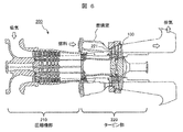
- FIG. 6 is a schematic cross-sectional view showing an example of a gas turbine equipped with the Co-based alloy product according to the present invention.
- the gas turbine 200 is roughly composed of a compressor unit 210 that compresses intake air and a turbine unit 220 that blows combustion gas of fuel to turbine blades to obtain rotational power.
- the high temperature member of the present invention can be suitably used as the turbine nozzle 221 in the turbine section 220 or the turbine vane 100.
- the high temperature member of the present invention is not limited to gas turbine applications, but may be used for other turbine applications (for example, steam turbine applications), and may be used under high temperature environments in other machines/apparatuses. It may be a member.
- FIG. 7 is an example of a Co-based alloy product according to the present invention, and is a schematic perspective view showing a heat exchanger as a high temperature member.
- the heat exchanger 300 shown in FIG. 7 is an example of a plate fin type heat exchanger, and basically has a structure in which separate layers 301 and fin layers 302 are alternately laminated. Both ends of the fin layer 302 in the flow channel width direction are sealed by side bar portions 303. By alternately circulating the high temperature fluid and the low temperature fluid through the adjacent fin layers 302, heat exchange is performed between the high temperature fluid and the low temperature fluid.
- the heat exchanger 300 according to the present invention is integrally formed without brazing or welding the components of the conventional heat exchanger (for example, the separate plate, the corrugated fin, the side bar), It can be made more heat resistant and lighter than a heat exchanger. Further, by forming an appropriate uneven shape on the surface of the flow path, the fluid can be turbulent and the heat transfer efficiency can be improved. Improvement of heat transfer efficiency leads to miniaturization of the heat exchanger.
- alloy powder preparation step S1 Preparation of alloy powder IA-1 to IA-7 and CA-1 to CA-5) Co-based alloy powders having the chemical compositions shown in Table 1 were prepared (alloy powder preparation step S1). Specifically, first, after mixing the raw materials, a master alloy ingot production step S1a for producing a master alloy ingot (mass: about 2 kg) by melting and casting by a vacuum high frequency induction melting method was performed. Next, an atomizing element step S1b of remelting the mother alloy ingot and forming an alloy powder by a gas atomizing method in an argon gas atmosphere was performed.
- an alloy powder classifying step S1c for controlling the particle size of the alloy powder was performed to classify the powder particle size to the range of 5 to 25 ⁇ m.
- the invention alloy powders IA-1 to IA-7 are alloy powders having a chemical composition satisfying the provisions of the present invention.
- the comparative alloy powder CA-1 has a C content and a Cr content outside the provisions of the present invention.
- the C content rate, the Ni content rate, and the total content rate of “Ti+Zr+Hf+V+Nb+Ta” are out of the regulation of the present invention.
- the C content rate, the N content rate, and the total content rate of “Ti+Zr+Hf+V+Nb+Ta” are out of the regulation of the present invention.
- the total content of “Ti+Zr+Hf+V+Nb+Ta” is outside the regulation of the present invention.
- the W content and the total content of “Ti+Zr+Hf+V+Nb+Ta” are out of the regulation of the present invention.
- Example 2 (Examination of SLM conditions in the selective laser melting process) An AM body (diameter 8 mm x length 10 mm) was formed by the SLM method using the IA-4 alloy powder prepared in Experiment 1 (selective laser melting step S2).
- the control of the local heat input amount corresponds to the control of the cooling rate.
- the average size of the segregated cells was measured by observing the microstructure of each AM body prepared above. The microstructure was observed by SEM. The average size of the segregation cells was measured on the obtained SEM observation image by image analysis using image processing software (ImageJ, public domain software developed by National Institutes of Health (NIH) in the United States).
- FIG. 8 is an example of SLM conditions in the selective laser melting step S2, and is a graph showing the relationship between the thickness of the alloy powder bed and the local heat input.
- FIG. 8 as a result of observing the microstructure of the formed AM body, those having an average size of segregated cells in the range of 0.15 to 1.5 ⁇ m were judged as “passed” and indicated by “ ⁇ ” in the figure, and other than that. Those were judged to be "failed” and indicated by "x” in the figure.
- the SLM conditions in the selective laser melting step S2 are as follows: the thickness h of the alloy powder bed (unit: ⁇ m), the laser light output P (unit: W), and the laser light scanning speed S (unit: It is confirmed that it is preferable to control so that the relationship with (mm/s) satisfies “15 ⁇ h ⁇ 150” and “67(P/S)-3.5 ⁇ h ⁇ 2222(P/S)+13”. .. That is, the hatched area is the area for acceptance determination.
- Example 3 (Examination of heat treatment conditions in the first heat treatment step) An AM body (diameter 10 mm x length 50 mm) was formed by the SLM method using the IA-5 and IA-6 alloy powders prepared in Experiment 1 (selective laser melting step S2).
- Each AM body prepared above was heat-treated at 950 to 1250 ° C. for 2 to 4 hours (first heat treatment step S3).
- each AM body subjected to the first heat treatment is subjected to a heat treatment of holding at 900° C. for 4 hours (second heat treatment step S4), and a Co-based alloy using IA-5 powder and IA-6 powder.
- Products IAP-5a to IAP-5d, IAP-6a to IAP-6d
- Test pieces for mechanical property testing were collected from each of the produced alloy products and subjected to mechanical property testing.
- a creep test was performed under conditions of a temperature of 850°C and a stress of 168 MPa, and the creep rupture time was measured. From the required characteristics of the high temperature member targeted by the present invention, a creep rupture time of 1200 hours or more was determined as "pass”, and a creep rupture time of less than 1200 hours was determined as "fail". It can be said that this creep characteristic is equivalent to that of the Ni-based alloy material.
- Each AM body prepared above was heat-treated at 1000 ° C. for 4 hours (first heat treatment step S3).
- each AM body subjected to the first heat treatment is subjected to a heat treatment of holding at 850° C. for 1 hour (second heat treatment step S4) to produce a Co-based alloy using IA-1 to IA-7 powders.
- Products IAP-1-1 to IAP-7-1, and Co-based alloy products CAP-1-1 to CAP-5-1 using powders CA-1 to CA-5 were produced.
- Microstructure observation and mechanical property test From the Co-based alloy products IAP-1-1 to IAP-7-1 and CAP-1-1 to CAP-5-1 produced above, sample pieces for microstructural observation and mechanical property test were collected. Then, microstructure observation and mechanical property test were performed.
- IA-1 to IA-7 having the chemical composition specified in the present invention are preferable as the starting powder of the Co-based alloy product. Further, by dispersing and precipitating the precipitated strengthened carbide phase particles in the matrix crystal grains at an average interparticle distance of 0.15 to 1.5 ⁇ m and precipitating the grain boundary strengthened carbide phase particles on the grain boundaries of the matrix, Co It was confirmed that the creep characteristics of the base alloy product could be improved.
- Turbine stationary blade 101... Inner ring side end wall, 102... Blade section, 103... Outer ring side end wall, 200... Gas turbine, 210... Compressor section, 220... Turbine section, 221... Turbine nozzle, 300... Heat exchange Container, 301... Separate layer, 302... Fin layer, 303... Sidebar part.
Landscapes
- Engineering & Computer Science (AREA)
- Chemical & Material Sciences (AREA)
- Materials Engineering (AREA)
- Manufacturing & Machinery (AREA)
- Mechanical Engineering (AREA)
- Organic Chemistry (AREA)
- Metallurgy (AREA)
- Physics & Mathematics (AREA)
- General Engineering & Computer Science (AREA)
- Thermal Sciences (AREA)
- Nanotechnology (AREA)
- Plasma & Fusion (AREA)
- Automation & Control Theory (AREA)
- Crystallography & Structural Chemistry (AREA)
- Powder Metallurgy (AREA)
Abstract
本発明は、析出強化Ni基合金材と同等以上の機械的特性を有するCo基合金製造物、その製造方法および該製造物の基となる物品を提供することを目的とする。本発明に係るCo基合金製造物は、0.08~0.25質量%のCと、0.1質量%以下のBと、10~30質量%のCrとを含み、Feを5質量%以下でNiを30質量%以下で含み、FeおよびNiの合計が30質量%以下であり、Wおよび/またはMoを含み、WおよびMoの合計が5質量%以上12質量%以下であり、Ti、Zr、Hf、V、NbおよびTaの1種以上を合計0.5質量%以上2質量%以下で含み、0.5質量%以下のSiと、0.5質量%以下のMnと、0.003~0.04質量%のNとを含み、残部がCoと不純物とからなり、前記不純物は、0.5質量%以下のAlと、0.04質量%以下のOとを含む、化学組成を有し、前記製造物は、母相結晶の多結晶体であり、MC型炭化物相の粒子とM23C6型炭化物相の粒子とが共析出しており、前記MC型炭化物相の粒子は、0.13μm以上2μm以下の平均粒子間距離で前記母相結晶の粒内に分散析出しており、前記M23C6型炭化物相の粒子は、前記母相結晶の粒界上に析出している、ことを特徴とする。
Description
本発明は、機械的特性に優れたコバルト基合金材に関し、特に、コバルト基合金製造物、該製造物の製造方法、およびコバルト基合金物品に関するものである。
コバルト(Co)基合金材は、ニッケル(Ni)基合金材とともに代表的な耐熱合金材料であり、超合金とも称されて高温部材(高温環境下で使用される部材、例えば、ガスタービンや蒸気タービンの部材)に広く用いられている。Co基合金材は、Ni基合金材と比べて材料コストは高いものの耐食性や耐摩耗性が優れており、固溶強化し易いことから、タービン静翼やタービン燃焼器部材などとして用いられてきた。
耐熱合金材料において、現在までに行われてきた種々の合金組成の改良および製造プロセスの改良によって、Ni基合金材では、γ’相(例えばNi3(Al,Ti)相)の析出による強化が開発され現在主流になっている。一方、Co基合金材においては、Ni基合金材のγ’相のような機械的特性向上に大きく寄与する金属間化合物相が析出しづらいことから、炭化物相による析出強化が研究されてきた。
例えば、特許文献1(特開昭61-243143)には、結晶粒径が10μm以下であるコバルト基合金の基地に、粒径が0.5から10μmである塊状及び粒状の炭化物を析出させてなることを特徴とするCo基超塑性合金が開示されている。また、前記コバルト基合金は、重量比でC:0.15~1%、Cr:15~40%、W及び又はMo:3~15%、B:1%以下、Ni:0~20%、Nb:0~1.0%、Zr:0~1.0%、Ta:0~1.0%、Ti:0~3%、Al:0~3%、及び残部Coからなること、が開示されている。特許文献1によると、低い温度領域(例えば、950℃)でも超塑性を示して70%以上の伸び率を有し、かつ鍛造加工等の塑性加工により複雑形状物を作製しえるCo基超塑性合金を提供できる、とされている。
特許文献2(特開平7-179967)には、重量%にて、Cr:21~29%、Mo:15~24%、B:0.5~2%、Si:0.1%以上で0.5%未満、C:1%を越えて2%以下、Fe:2%以下、Ni:2%以下及び残部実質的にCoからなる、耐食性、耐摩耗性及び高温強度にすぐれるCo基合金が開示されている。特許文献2によると、当該Co基合金は、Co、Cr、Mo、Siの4元系合金相にモリブデン硼化物及びクロム炭化物が比較的微細に分散した複合組織を有し、良好な耐食性及び耐摩耗性、並びに高い強度を備える、とされている。
ところで、近年、複雑形状を有する最終製品をニアネットシェイプで製造する技術として、積層造形法(Additive Manufacturing、AM法)などの三次元造形技術(いわゆる3Dプリンティング)が注目され、該三次元造形技術を耐熱合金部材へ適用する研究開発が活発に行われている。
例えば、特許文献3(特表2016-535169)には、以下のステップを含む層形成方法:a)20%未満の空隙率を有する粉体状または懸濁液状の顆粒状複合材料の原料を供給するステップ、b)前記複合材料の第一部分を、目標物表面に堆積するステップ、c)前記第一部分の前記複合材料にエネルギーを供給して、前記第一部分の前記複合材料を焼結、融合または融解して第一層を形成するステップ、d)前記第一層の上に前記複合材料の第二部分を堆積するステップ、e)前記第二部分の前記複合材料にエネルギーを供給して、前記第二部分の前記複合材料を焼結、融合または融解して第二層を形成するステップ、であり、前記エネルギーがレーザにより供給される方法、が開示されている。
特許文献3(特表2016-535169)によると、選択的レーザ融解法(SLM法)または直接金属レーザ融解法(DMLM法)は、一般に、1種の材料(純チタンやTi-6Al-4Vのような単一合金)に対し有益とのことである。対照的に、複数材料、合金、または合金とプラスチック、セラミック、ポリマー、炭化物、ガラスなどのその他材料の組み合わせの場合は、選択的レーザ焼結法(SLS法)または直接金属レーザ焼結法(DMLS法)を適用するのが一般的とのことである。なお、焼結は、融解とは別の技術概念であり、焼結プロセスは、材料粉末を完全には融解しないが、該粉末が分子レベルで共に融合することができる点まで加熱するプロセスとのことである。
3Dプリンティングによる合金部材の製造は、タービン翼のような複雑形状を有する部材であっても直接的に造形できることから、製造ワークタイムの短縮や製造歩留まりの向上の観点(すなわち、製造コストの低減の観点)で大変魅力的な技術である。
特許文献1~2に記載されたようなCo基合金材は、それら以前のCo基合金材に比して高い機械的特性を有すると考えられるが、近年の析出強化Ni基合金材と比較すると、残念ながら十分な機械的特性を有しているとは言えない。そのため、現在のところ、高温部材用途の積層造形体(AM体)の研究は、析出強化Ni基合金材を対象としているものが多い。
しかしながら、析出強化Ni基合金のAM体では、機械的特性の要となるγ’相の生成が阻害されたり製造物中に内部欠陥を生じさせたりする不具合が発生し易く、結果として期待される機械的特性が十分に得られないという問題が生じている。これは、高温部材として利用される現在の析出強化Ni基合金材は、高真空中での溶解・鋳造プロセスを前提として最適化されているため、AM法用の合金粉末を用意する段階やAM法の段階において、γ’相を構成するAl成分およびTi成分の酸化や窒化が起こり易いためと考えられている。
一方、特許文献1~2に記載されたようなCo基合金材は、Ni基合金材のγ’相のような金属間化合物相の析出を前提としないことから、酸化し易いAlやTiを多く含有させておらず、大気中での溶解・鋳造プロセスが利用可能である。そのため、AM法用の合金粉末の作製やAM体の作製に有利であると考えられる。また、Co基合金材は、Ni基合金材と同等以上の耐食性や耐摩耗性を有する利点がある。
しかしながら、前述したように、従来のCo基合金材は、γ’相析出強化Ni基合金材に比して機械的特性が低いという弱点を有する。言い換えると、γ’相析出強化Ni基合金材と同等以上の機械的特性(例えば、温度900℃、応力98 MPaの条件下でクリープ試験を行ったときのクリープ破断時間が1100時間以上)を達成することができれば、Co基合金AM体は、大変魅力的な高温部材となりうる。
本発明は、上記のような課題に鑑みてなされたものであり、その目的は、析出強化Ni基合金材と同等以上の機械的特性を有するCo基合金製造物およびその製造方法を提供することにある。また、Co基合金製造物の基となる物品を提供することを目的とする。
(I)本発明の一態様は、Co基合金からなる製造物であって、
前記Co基合金は、
0.08質量%以上0.25質量%以下の炭素(C)と、
0.1質量%以下のホウ素(B)と、
10質量%以上30質量%以下のクロム(Cr)とを含み、
鉄(Fe)を5質量%以下でニッケル(Ni)を30質量%以下で含み、前記Feおよび前記Niの合計が30質量%以下であり、
タングステン(W)および/またはモリブデン(Mo)を含み、前記Wおよび前記Moの合計が5質量%以上12質量%以下であり、
チタン(Ti)、ジルコニウム(Zr)、ハフニウム(Hf)、バナジウム(V)、ニオブ(Nb)およびタンタル(Ta)の1種以上を合計0.5質量%以上2質量%以下で含み、
0.5質量%以下のケイ素(Si)と、
0.5質量%以下のマンガン(Mn)と、
0.003質量%以上0.04質量%以下の窒素(N)とを含み、
残部がCoと不純物とからなり、
前記不純物は、
0.5質量%以下のアルミニウム(Al)と、
0.04質量%以下の酸素(O)とを含む、化学組成を有し、
前記製造物は、母相結晶の多結晶体であり、MC型炭化物相の粒子とM23C6型炭化物相の粒子とが共析出しており、
前記MC型炭化物相の粒子は、0.13μm以上2μm以下の平均粒子間距離で前記母相結晶の粒内に分散析出しており、
前記M23C6型炭化物相の粒子は、前記母相結晶の粒界上に析出している、
ことを特徴とするCo基合金製造物を提供するものである。
本発明は、上記のCo基合金製造物(I)において、以下のような改良や変更を加えることができる。
(i)前記MC型炭化物相の粒子は、前記Ti、前記Zr、前記Hf、前記V、前記Nbおよび/または前記Taを含むMC型炭化物相の粒子であり、
前記M23C6型炭化物相の粒子は、前記Cr、前記Fe、前記W、前記Moおよび/または前記Mnを含むM23C6型炭化物相の粒子である。
(ii)前記Co基合金の前記化学組成は、
前記Tiを含む場合、該Tiは0.01質量%以上1質量%以下であり、
前記Zrを含む場合、該Zrは0.05質量%以上1.5質量%以下であり、
前記Hfを含む場合、該Hfは0.01質量%以上0.5質量%以下であり、
前記Vを含む場合、該Vは0.01質量%以上0.5質量%以下であり、
前記Nbを含む場合、該Nbは0.02質量%以上1質量%以下であり、
前記Taを含む場合、該Taは0.05質量%以上1.5質量%以下である。
(iii)前記製造物は、温度850℃、応力168 MPaの条件下でクリープ試験を行った場合のクリープ破断時間が1200時間以上である。
(iv)前記製造物は、高温部材である。
(v)前記高温部材は、タービン静翼、タービン動翼、タービン燃焼器ノズルまたは熱交換器である。
(II)本発明の他の一態様は、上記のCo基合金製造物の製造方法であって、
前記化学組成を有するCo基合金粉末を用意する合金粉末用意工程と、
前記Co基合金粉末を敷き詰めて所定厚さの合金粉末床を用意する合金粉末床用意素工程と、前記合金粉末床の所定の領域にレーザ光を照射して該領域の前記Co基合金粉末を局所溶融急速凝固させるレーザ溶融凝固素工程と、を繰り返して積層造形体を形成する選択的レーザ溶融(SLM)工程と、
前記積層造形体に対して、750℃以上1100℃未満の温度範囲の第1熱処理を施す第1熱処理工程と、
前記第1熱処理を施した前記積層造形体に対して、600℃以上1000℃以下の温度範囲で前記第1熱処理よりも低い温度の第2熱処理を施す第2熱処理工程とを有し、
前記SLM工程において、前記合金粉末床の前記所定厚さh(単位:μm)と前記レーザ光の出力P(単位:W)と前記レーザ光の走査速度S(単位:mm/s)との関係が「15 <h< 150」かつ「67(P/S)-3.5 <h< 2222(P/S)+13」を満たすように、前記所定厚さhと前記出力Pと前記走査速度Sとを制御する、
ことを特徴とするCo基合金製造物の製造方法。
本発明は、上記のCo基合金製造物の製造方法(II)において、以下のような改良や変更を加えることができる。
(vi)前記合金粉末用意工程は、前記Co基合金粉末を5μm以上100μm以下の粒径範囲に分級する合金粉末分級素工程を含む。
(vi)前記合金粉末用意工程は、前記Co基合金粉末を5μm以上100μm以下の粒径範囲に分級する合金粉末分級素工程を含む。
本発明によれば、析出強化Ni基合金材と同等以上の機械的特性を有するCo基合金製造物およびその製造方法を提供することができる。また、Co基合金製造物の基となる物品を提供することができる。
[本発明の基本思想]
前述したように、Co基合金材では、炭化物相の析出による強化が種々研究開発されてきた。析出強化に寄与する炭化物相としては、例えば、Ti、Zr、Hf、V、Nb、TaのMC型炭化物相、およびそれら金属元素の複合炭化物相が挙げられる。
前述したように、Co基合金材では、炭化物相の析出による強化が種々研究開発されてきた。析出強化に寄与する炭化物相としては、例えば、Ti、Zr、Hf、V、Nb、TaのMC型炭化物相、およびそれら金属元素の複合炭化物相が挙げられる。
Ti、Zr、Hf、V、Nb、Taの各成分および炭化物相を形成する上で不可欠なC成分は、Co基合金の溶融凝固の際に、最終凝固部(例えば、デンドライト境界や結晶粒界)に偏析し易いという性状がある。そのため、従来のCo基合金材では、当該炭化物相粒子は、母相のデンドライト境界や結晶粒界に沿って析出する。例えば、Co基合金の普通鋳造材では、通常、デンドライト境界の平均間隔や平均結晶粒径が101~102μmオーダになるため、炭化物相粒子の平均間隔も101~102μmオーダになる。また、レーザ溶接などの凝固速度が比較的速いプロセスであっても、凝固部における炭化物相粒子の平均間隔は5μm程度である。
合金における析出強化は、析出物同士の平均間隔に反比例することが一般的に知られており、析出強化が有効になるのは、析出物同士の平均間隔が2μm程度以下の場合と言われている。しかしながら、上述した従来技術では、析出物同士の平均間隔がそのレベルに達しておらず、十分な析出強化の作用効果が得られない。言い換えると、従来技術では、合金強化に寄与する炭化物相粒子を微細分散析出させることが難しかった。これが、析出強化Ni基合金材に比して、Co基合金材は機械的特性が不十分と言われてきた主な要因である。
なお、Co基合金において析出しうる他の炭化物相として、Cr炭化物相がある。Cr成分はCo基合金母相への固溶性が高く偏析しづらいことから、Cr炭化物相は母相結晶粒内に分散析出させることが可能である。しかしながら、Cr炭化物相は、Co基合金母相結晶との格子整合性が低く、析出強化相としてはそれほど有効でないことが知られている。
本発明者等は、Co基合金材において、析出強化に寄与する炭化物相粒子を母相結晶粒内に分散析出させることができれば、Co基合金材の機械的特性を飛躍的に向上させることができると考えた。また、Co基合金材が元々有する良好な耐食性や耐摩耗性と併せると、析出強化Ni基合金材を凌駕する耐熱合金材を提供できると考えた。
そこで、本発明者等は、そのようなCo基合金材を得るための合金組成および製造方法について鋭意研究した。その結果、合金組成を最適化するとともに、AM法(特に、選択的レーザ溶融法)を利用した製造において、局所溶融・急速凝固のための入熱量を所定の範囲に制御することにより、Co基合金材(AM体)の母相結晶粒内に、特定成分(合金強化に寄与する炭化物相を形成する成分)が偏析した微小サイズの偏析セルが形成されることを見出した。さらに、得られたAM体に所定の熱処理を施すと、母相結晶の粒内にMC型炭化物相の粒子が微細分散析出し、母相結晶の粒界上にM23C6型炭化物相の粒子が析出した微細組織が得られることを見出した。本発明は、当該知見に基づいて完成されたものである。
以下、図面を参照しながら、本発明に係る実施形態を製造手順に沿って説明する。ただし、本発明はここで取り上げた実施形態に限定されることはなく、発明の技術的思想を逸脱しない範囲で、公知技術と適宜組み合わせたり公知技術に基づいて改良したりすることが可能である。
[Co基合金製造物の製造方法]
図1は、本発明に係るCo基合金製造物の製造方法の工程例を示すフロー図である。図1に示したように、本発明に係るCo基合金製造物の製造方法は、概略的に、Co基合金粉末を用意する合金粉末用意工程(S1)と、用意したCo基合金粉末を用いて所望形状のAM体を形成する選択的レーザ溶融工程(S2)と、形成したAM体に対して第1熱処理を施す第1熱処理工程(S3)と、第1熱処理を施したAM体に対して第2熱処理を施す第2熱処理工程(S4)と、を有する。
図1は、本発明に係るCo基合金製造物の製造方法の工程例を示すフロー図である。図1に示したように、本発明に係るCo基合金製造物の製造方法は、概略的に、Co基合金粉末を用意する合金粉末用意工程(S1)と、用意したCo基合金粉末を用いて所望形状のAM体を形成する選択的レーザ溶融工程(S2)と、形成したAM体に対して第1熱処理を施す第1熱処理工程(S3)と、第1熱処理を施したAM体に対して第2熱処理を施す第2熱処理工程(S4)と、を有する。
また、図1には図示していないが、第2熱処理工程S4によって得られたCo基合金製造物に対して、必要に応じて、耐食性被覆層を形成する工程や表面仕上げの工程を更に行ってもよい。なお、合金粉末用意工程S1によって得られたCo基合金粉末は、本発明に係るCo基合金物品となりえる。
以下、各工程をより詳細に説明する。
(合金粉末用意工程)
本工程S1は、所定の化学組成を有するCo基合金粉末を用意する工程である。該化学組成は、0.08質量%以上0.25質量%以下のCと、0.1質量%以下のBと、10質量%以上30質量%以下のCrとを含み、Feを5質量%以下でNiを30質量%以下で含み、FeおよびNiの合計が30質量%以下であり、Wおよび/またはMoを含み、WおよびMoの合計が5質量%以上12質量%以下であり、Ti、Zr、Hf、V、NbおよびTaの1種以上を合計0.5質量%以上2質量%以下で含み、0.5質量%以下のSiと、0.5質量%以下のMnと、0.003質量%以上0.04質量%以下のNとを含み、残部がCoと不純物とからなることが好ましい。不純物としては、0.5質量%以下のAlと、0.04質量%以下のOとを含んでもよい。
本工程S1は、所定の化学組成を有するCo基合金粉末を用意する工程である。該化学組成は、0.08質量%以上0.25質量%以下のCと、0.1質量%以下のBと、10質量%以上30質量%以下のCrとを含み、Feを5質量%以下でNiを30質量%以下で含み、FeおよびNiの合計が30質量%以下であり、Wおよび/またはMoを含み、WおよびMoの合計が5質量%以上12質量%以下であり、Ti、Zr、Hf、V、NbおよびTaの1種以上を合計0.5質量%以上2質量%以下で含み、0.5質量%以下のSiと、0.5質量%以下のMnと、0.003質量%以上0.04質量%以下のNとを含み、残部がCoと不純物とからなることが好ましい。不純物としては、0.5質量%以下のAlと、0.04質量%以下のOとを含んでもよい。
C:0.08質量%以上0.25質量%以下
C成分は、析出強化相となるMC型炭化物相(Ti、Zr、Hf、V、Nbおよび/またはTaの炭化物相、以下、析出強化炭化物相と称する場合がある)および母相結晶の粒界滑りを抑制する相となるM23C6型炭化物相(Cr、Fe、W、Moおよび/またはMnの炭化物相、以下、粒界強化炭化物相と称する場合がある)を構成する重要な成分である。C成分の含有率は、0.08質量%以上0.25質量%以下が好ましく、0.1質量%以上0.2質量%以下がより好ましく、0.12質量%以上0.18質量%以下が更に好ましい。C含有率が0.08質量%未満になると、析出強化炭化物相および粒界強化炭化物相の析出量が不足し、機械的特性向上の作用効果が十分に得られない。一方、C含有率が0.25質量%超になると、Cr炭化物相が過剰析出したり過度に硬化したりすることで、合金材の延性や靱性が低下する。
C成分は、析出強化相となるMC型炭化物相(Ti、Zr、Hf、V、Nbおよび/またはTaの炭化物相、以下、析出強化炭化物相と称する場合がある)および母相結晶の粒界滑りを抑制する相となるM23C6型炭化物相(Cr、Fe、W、Moおよび/またはMnの炭化物相、以下、粒界強化炭化物相と称する場合がある)を構成する重要な成分である。C成分の含有率は、0.08質量%以上0.25質量%以下が好ましく、0.1質量%以上0.2質量%以下がより好ましく、0.12質量%以上0.18質量%以下が更に好ましい。C含有率が0.08質量%未満になると、析出強化炭化物相および粒界強化炭化物相の析出量が不足し、機械的特性向上の作用効果が十分に得られない。一方、C含有率が0.25質量%超になると、Cr炭化物相が過剰析出したり過度に硬化したりすることで、合金材の延性や靱性が低下する。
B:0.1質量%以下
B成分は、結晶粒界の接合性の向上(いわゆる粒界強化)に寄与する成分である。B成分は必須成分ではないが、含有させる場合、0.1質量%以下が好ましく、0.005質量%以上0.05質量%以下がより好ましい。B含有率が0.1質量%超になると、AM体形成時に割れ(例えば、凝固割れ)が発生し易くなる。
B成分は、結晶粒界の接合性の向上(いわゆる粒界強化)に寄与する成分である。B成分は必須成分ではないが、含有させる場合、0.1質量%以下が好ましく、0.005質量%以上0.05質量%以下がより好ましい。B含有率が0.1質量%超になると、AM体形成時に割れ(例えば、凝固割れ)が発生し易くなる。
Cr:10質量%以上30質量%以下
Cr成分は、耐食性や耐酸化性の向上に寄与する成分であり、かつ粒界強化炭化物相を構成する成分である。Cr成分の含有率は、10質量%以上30質量%以下が好ましく、15質量%以上27質量%以下がより好ましい。Co基合金製造物の最表面に耐食性被覆層を別途設けるような場合は、Cr成分の含有率は、10質量%以上18質量%以下が更に好ましい。Cr含有率が10質量%未満になると、作用効果(耐食性や耐酸化性の向上、粒界強化炭化物相の生成)が十分に得られない。一方、Cr含有率が30質量%超になると、脆性のσ相が生成したりCr炭化物相が過剰生成したりして機械的特性(靱性、延性、強さ)が低下する。
Cr成分は、耐食性や耐酸化性の向上に寄与する成分であり、かつ粒界強化炭化物相を構成する成分である。Cr成分の含有率は、10質量%以上30質量%以下が好ましく、15質量%以上27質量%以下がより好ましい。Co基合金製造物の最表面に耐食性被覆層を別途設けるような場合は、Cr成分の含有率は、10質量%以上18質量%以下が更に好ましい。Cr含有率が10質量%未満になると、作用効果(耐食性や耐酸化性の向上、粒界強化炭化物相の生成)が十分に得られない。一方、Cr含有率が30質量%超になると、脆性のσ相が生成したりCr炭化物相が過剰生成したりして機械的特性(靱性、延性、強さ)が低下する。
Ni:30質量%以下
Ni成分は、Co成分と類似した特性を有しかつCoに比して安価なことから、Co成分の一部を置き換えるかたちで含有させることができる成分である。Ni成分は必須成分ではないが、含有させる場合、30質量%以下が好ましく、20質量%以下がより好ましく、5質量%以上15質量%以下が更に好ましい。Ni含有率が30質量%超になると、Co基合金の特徴である耐摩耗性や局所応力への耐性が低下する。これは、Coの積層欠陥エネルギーとNiのそれとの差異に起因すると考えられる。
Ni成分は、Co成分と類似した特性を有しかつCoに比して安価なことから、Co成分の一部を置き換えるかたちで含有させることができる成分である。Ni成分は必須成分ではないが、含有させる場合、30質量%以下が好ましく、20質量%以下がより好ましく、5質量%以上15質量%以下が更に好ましい。Ni含有率が30質量%超になると、Co基合金の特徴である耐摩耗性や局所応力への耐性が低下する。これは、Coの積層欠陥エネルギーとNiのそれとの差異に起因すると考えられる。
Fe:5質量%以下
Fe成分は、Niよりもはるかに安価でありかつNi成分と類似した性状を有することから、Ni成分の一部を置き換えるかたちで含有させることができる成分である。また、粒界強化炭化物相を構成しうる成分でもある。FeおよびNiの合計含有率は30質量%以下が好ましく、20質量%以下がより好ましく、5質量%以上15質量%以下が更に好ましい。Fe成分は必須成分ではないが、含有させる場合、Ni含有率よりも少ない範囲で5質量%以下が好ましく、3質量%以下がより好ましい。Fe含有率が5質量%超になると、耐食性や機械的特性の低下要因になる。
Fe成分は、Niよりもはるかに安価でありかつNi成分と類似した性状を有することから、Ni成分の一部を置き換えるかたちで含有させることができる成分である。また、粒界強化炭化物相を構成しうる成分でもある。FeおよびNiの合計含有率は30質量%以下が好ましく、20質量%以下がより好ましく、5質量%以上15質量%以下が更に好ましい。Fe成分は必須成分ではないが、含有させる場合、Ni含有率よりも少ない範囲で5質量%以下が好ましく、3質量%以下がより好ましい。Fe含有率が5質量%超になると、耐食性や機械的特性の低下要因になる。
Wおよび/またはMo:合計5質量%以上12質量%以下
W成分およびMo成分は、母相の固溶強化に寄与する成分であり、一部は粒界強化炭化物相を構成しうる成分でもある。W成分および/またはMo成分(W成分およびMo成分の1種以上)の合計含有率は、5質量%以上12質量%以下が好ましく、7質量%以上10質量%以下がより好ましい。W成分とMo成分との合計含有率が5質量%未満になると、母相の固溶強化が不十分になる。一方、W成分とMo成分との合計含有率が12質量%超になると、脆性のσ相が生成し易くなって機械的特性(靱性、延性)が低下する。
W成分およびMo成分は、母相の固溶強化に寄与する成分であり、一部は粒界強化炭化物相を構成しうる成分でもある。W成分および/またはMo成分(W成分およびMo成分の1種以上)の合計含有率は、5質量%以上12質量%以下が好ましく、7質量%以上10質量%以下がより好ましい。W成分とMo成分との合計含有率が5質量%未満になると、母相の固溶強化が不十分になる。一方、W成分とMo成分との合計含有率が12質量%超になると、脆性のσ相が生成し易くなって機械的特性(靱性、延性)が低下する。
Re:2質量%以下
Re成分は、母相の固溶強化に寄与すると共に、耐食性の向上に寄与する成分である。Re成分は必須成分ではないが、含有させる場合、W成分またはMo成分の一部を置き換えるかたちで2質量%以下が好ましく、0.5質量%以上1.5質量%以下がより好ましい。Re含有率が2質量%超になると、Re成分の作用効果が飽和するのに加えて、材料コストの増加がデメリットになる。
Re成分は、母相の固溶強化に寄与すると共に、耐食性の向上に寄与する成分である。Re成分は必須成分ではないが、含有させる場合、W成分またはMo成分の一部を置き換えるかたちで2質量%以下が好ましく、0.5質量%以上1.5質量%以下がより好ましい。Re含有率が2質量%超になると、Re成分の作用効果が飽和するのに加えて、材料コストの増加がデメリットになる。
Ti、Zr、Hf、V、NbおよびTaの1種以上:合計0.5質量%以上2質量%以下
Ti成分、Zr成分、Hf成分、V成分、Nb成分およびTa成分は、析出強化炭化物相(MC型炭化物相)を構成する重要な成分である。Ti、Zr、Hf、V、NbおよびTa成分の1種以上の合計含有率は、0.5質量%以上2質量%以下が好ましく、0.5質量%以上1.8質量%以下がより好ましい。合計含有率が0.5質量%未満になると、析出強化炭化物相の析出量が不足し、機械的特性向上の作用効果が十分に得られない。一方、当該合計含有率が2質量%超になると、析出強化炭化物相粒子が粗大化したり脆性相(例えばσ相)の生成を促進したり析出強化に寄与しない酸化物相粒子を生成したりして機械的特性が低下する。
Ti成分、Zr成分、Hf成分、V成分、Nb成分およびTa成分は、析出強化炭化物相(MC型炭化物相)を構成する重要な成分である。Ti、Zr、Hf、V、NbおよびTa成分の1種以上の合計含有率は、0.5質量%以上2質量%以下が好ましく、0.5質量%以上1.8質量%以下がより好ましい。合計含有率が0.5質量%未満になると、析出強化炭化物相の析出量が不足し、機械的特性向上の作用効果が十分に得られない。一方、当該合計含有率が2質量%超になると、析出強化炭化物相粒子が粗大化したり脆性相(例えばσ相)の生成を促進したり析出強化に寄与しない酸化物相粒子を生成したりして機械的特性が低下する。
より具体的には、Tiを含有させる場合の含有率は、0.01質量%以上1質量%以下が好ましく、0.05質量%以上0.8質量%以下がより好ましい。
Zrを含有させる場合の含有率は、0.05質量%以上1.5質量%以下が好ましく、0.1質量%以上1.2質量%以下がより好ましい。なお、機械的強度の観点からは、Zr成分を必須成分とすることが更に好ましい。
Hfを含有させる場合の含有率は、0.01質量%以上0.5質量%以下が好ましく、0.02質量%以上0.1質量%以下がより好ましい。
Vを含有させる場合の含有率は、0.01質量%以上0.5質量%以下が好ましく、0.02質量%以上0.1質量%以下がより好ましい。
Nbを含有させる場合の含有率は、0.02質量%以上1質量%以下が好ましく、0.05質量%以上0.8質量%以下がより好ましい。
Taを含有させる場合の含有率は、0.05質量%以上1.5質量%以下が好ましく、0.1質量%以上1.2質量%以下がより好ましい。
Si:0.5質量%以下
Si成分は、脱酸素の役割を担って機械的特性の向上に寄与する成分である。Si成分は必須成分ではないが、含有させる場合、0.5質量%以下が好ましく、0.01質量%以上0.3質量%以下がより好ましい。Si含有率が0.5質量%超になると、酸化物(例えばSiO2)の粗大粒子を形成して機械的特性の低下要因になる。
Si成分は、脱酸素の役割を担って機械的特性の向上に寄与する成分である。Si成分は必須成分ではないが、含有させる場合、0.5質量%以下が好ましく、0.01質量%以上0.3質量%以下がより好ましい。Si含有率が0.5質量%超になると、酸化物(例えばSiO2)の粗大粒子を形成して機械的特性の低下要因になる。
Mn:0.5質量%以下
Mn成分は、脱酸素・脱硫の役割を担って機械的特性の向上や耐腐食性の向上に寄与する成分である。また、粒界強化炭化物相を構成しうる成分でもある。Mn成分は必須成分ではないが、含有させる場合、0.5質量%以下が好ましく、0.01質量%以上0.3質量%以下がより好ましい。Mn含有率が0.5質量%超になると、硫化物(例えばMnS)の粗大粒子を形成して機械的特性や耐食性の低下要因になる。
Mn成分は、脱酸素・脱硫の役割を担って機械的特性の向上や耐腐食性の向上に寄与する成分である。また、粒界強化炭化物相を構成しうる成分でもある。Mn成分は必須成分ではないが、含有させる場合、0.5質量%以下が好ましく、0.01質量%以上0.3質量%以下がより好ましい。Mn含有率が0.5質量%超になると、硫化物(例えばMnS)の粗大粒子を形成して機械的特性や耐食性の低下要因になる。
N:0.003質量%以上0.04質量%以下
N成分は、析出強化炭化物相の安定生成に寄与する成分である。N成分の含有率は、0.003質量%以上0.04質量%以下が好ましく、0.005質量%以上0.03質量%以下がより好ましく、0.007質量%以上0.025質量%以下が更に好ましい。N含有率が0.003質量%未満になると、N成分の作用効果が十分に得られない。一方、N含有率が0.04質量%超になると、窒化物(例えばCr窒化物)の粗大粒子を形成して機械的特性の低下要因になる。
N成分は、析出強化炭化物相の安定生成に寄与する成分である。N成分の含有率は、0.003質量%以上0.04質量%以下が好ましく、0.005質量%以上0.03質量%以下がより好ましく、0.007質量%以上0.025質量%以下が更に好ましい。N含有率が0.003質量%未満になると、N成分の作用効果が十分に得られない。一方、N含有率が0.04質量%超になると、窒化物(例えばCr窒化物)の粗大粒子を形成して機械的特性の低下要因になる。
残部:Co成分+不純物
Co成分は、本合金の主要成分の一つであり、最大含有率の成分である。前述したように、Co基合金材は、Ni基合金材と同等以上の耐食性や耐摩耗性を有する利点がある。
Co成分は、本合金の主要成分の一つであり、最大含有率の成分である。前述したように、Co基合金材は、Ni基合金材と同等以上の耐食性や耐摩耗性を有する利点がある。
Al成分は、本合金の不純物の一つであり、意図的に含有させる成分ではない。ただし、0.5質量%以下のAl含有率であれば、Co基合金製造物の機械的特性に大きな悪影響を及ぼさないことから許容される。Al含有率が0.5質量%超になると、酸化物や窒化物(例えばAl2O3やAlN)の粗大粒子を形成して機械的特性の低下要因になる。
O成分も、本合金の不純物の一つであり、意図的に含有させる成分ではない。ただし、0.04質量%以下のO含有率であれば、Co基合金製造物の機械的特性に大きな悪影響を及ぼさないことから許容される。O含有率が0.04質量%超になると、各種酸化物(例えば、Ti酸化物、Zr酸化物、Al酸化物、Fe酸化物、Si酸化物)の粗大粒子を形成して機械的特性の低下要因になる。
本工程S1において、Co基合金粉末を用意する方法・手法に特段の限定はなく、従前の方法・手法を利用できる。例えば、所望の化学組成となるように原料を混合・溶解・鋳造して母合金塊(マスターインゴット)を作製する母合金塊作製素工程(S1a)と、該母合金塊から合金粉末を形成するアトマイズ素工程(S1b)とを行えばよい。また、アトマイズ方法にも特段の限定はなく、従前の方法・手法を利用できる。例えば、高純度・球形状粒子が得られるガスアトマイズ法や遠心力アトマイズ法を好ましく用いることができる。
合金粉末の粒径は、次工程の選択的レーザ溶融工程S2におけるハンドリング性や合金粉末床の充填性の観点から、5μm以上100μm以下が好ましく、10μm以上70μm以下がより好ましく、10μm以上50μm以下が更に好ましい。合金粉末の粒径が5μm未満になると、次工程S2において合金粉末の流動性が低下し(合金粉末床の形成性が低下し)、AM体の形状精度が低下する要因となる。一方、合金粉末の粒径が100μm超になると、次工程S2において合金粉末床の局所溶融・急速凝固の制御が難しくなり、合金粉末の溶融が不十分になったりAM体の表面粗さが増加したりする要因となる。
上記のことから、合金粉末の粒径を5μm以上100μm以下の範囲に分級する合金粉末分級素工程(S1c)を行うことは、好ましい。なお、本発明においては、アトマイズ素工程S1bで作製した合金粉末の粒径分布を測定した結果、所望の範囲内にあることを確認した場合も、本素工程S1cを行ったものと見なす。
(選択的レーザ溶融工程)
本工程S2は、用意したCo基合金粉末を用いて選択的レーザ溶融(SLM)法により所望形状のAM体を形成する工程である。具体的には、Co基合金粉末を敷き詰めて所定厚さの合金粉末床を用意する合金粉末床用意素工程(S2a)と、合金粉末床の所定の領域にレーザ光を照射して該領域のCo基合金粉末を局所溶融・急速凝固させるレーザ溶融凝固素工程(S2b)と、を繰り返してAM体を形成する工程である。
本工程S2は、用意したCo基合金粉末を用いて選択的レーザ溶融(SLM)法により所望形状のAM体を形成する工程である。具体的には、Co基合金粉末を敷き詰めて所定厚さの合金粉末床を用意する合金粉末床用意素工程(S2a)と、合金粉末床の所定の領域にレーザ光を照射して該領域のCo基合金粉末を局所溶融・急速凝固させるレーザ溶融凝固素工程(S2b)と、を繰り返してAM体を形成する工程である。
本工程S2においては、最終的なCo基合金製造物で望ましい微細組織(母相結晶粒内に析出強化炭化物相粒子が分散析出した微細組織)を得るために、該製造物の前駆体となるAM体の微細組織を制御する。そして、該AM体の微細組織を制御するために、合金粉末床の局所溶融・急速凝固を制御する。
より具体的には、合金粉末床の厚さh(単位:μm)とレーザ光の出力P(単位:W)とレーザ光の走査速度S(単位:mm/s)との関係において、「15 <h< 150」かつ「67(P/S)-3.5 <h< 2222(P/S)+13」を満たすように、合金粉末床の厚さhとレーザ光出力Pとレーザ光走査速度Sとを制御することが好ましい。当該制御条件を外れると、望ましい微細組織を有するAM体が得られない。
なお、レーザ光の出力Pおよびレーザ光の走査速度Sは、基本的にレーザ装置の構成に依存するが、例えば「10 ≦P≦ 1000」および「10 ≦S≦ 7000」の範囲内で選定すればよい。
(Co基合金積層造形体)
図2は、SLM工程S2で得られるCo基合金AM体の微細組織の一例を示す走査型電子顕微鏡(SEM)観察像である。図2に示したように、SLM工程S2で得られるCo基合金AM体は、今までに見たことのないような極めて特異的な微細組織を有している。
図2は、SLM工程S2で得られるCo基合金AM体の微細組織の一例を示す走査型電子顕微鏡(SEM)観察像である。図2に示したように、SLM工程S2で得られるCo基合金AM体は、今までに見たことのないような極めて特異的な微細組織を有している。
該AM体は、母相結晶の多結晶体であり、該多結晶体の結晶粒内には、平均サイズが0.13μm以上2μm以下の偏析セルが形成している。偏析セルの平均サイズは、機械的強度の観点から0.15μm以上1.5μm以下がより好ましい。偏析セルの境界領域上の一部には、炭化物相粒子が析出する場合があることが確認される。また、数多くの実験から、母相結晶の平均結晶粒径は5μm以上150μm以下が好ましいと確認された。
なお、本発明において、偏析セルのサイズとは、基本的に長径と短径との平均と定義するが、長径と短径とのアスペクト比が3以上の場合は、短径の2倍を採用するものとする。また、本発明における析出強化炭化物相の粒子の平均間隔は、当該粒子が偏析セルの境界領域上に析出することから、偏析セルのサイズで代表すると定義する。
走査型透過電子顕微鏡-エネルギー分散型X線分光法(STEM-EDX)を用いて、さらに詳細に微細組織観察を行ったところ、当該偏析セルは、微小セル間の境界領域(偏析セルの外周領域、細胞壁のような領域)に析出強化炭化物相を形成する成分(Ti、Zr、Hf、V、Nb、Ta、C)が偏析していることが確認された。また、偏析セルの境界領域上に析出した粒子は、MC型炭化物相の粒子であることが確認された。
なお、本AM体は、当然のことながら、母相結晶粒の粒界上にもMC型炭化物相を形成する成分の偏析やMC型炭化物相粒子の析出がある。
(第1熱処理工程)
本工程S3は、形成したCo基合金AM体に対して第1の熱処理を施す工程である。第1熱処理の条件としては、750℃以上1100℃未満の温度範囲の熱処理が好ましい。熱処理温度は、800℃以上1050℃以下がより好ましく、850℃以上1000℃以下が更に好ましい。熱処理における保持時間は、温度を考慮しながら0.5時間以上10時間以下の範囲で適宜設定すればよい。熱処理後の冷却方法に特段の限定はなく、例えば、油冷、水冷、空冷、炉冷のいずれでも構わない。
本工程S3は、形成したCo基合金AM体に対して第1の熱処理を施す工程である。第1熱処理の条件としては、750℃以上1100℃未満の温度範囲の熱処理が好ましい。熱処理温度は、800℃以上1050℃以下がより好ましく、850℃以上1000℃以下が更に好ましい。熱処理における保持時間は、温度を考慮しながら0.5時間以上10時間以下の範囲で適宜設定すればよい。熱処理後の冷却方法に特段の限定はなく、例えば、油冷、水冷、空冷、炉冷のいずれでも構わない。
図3は、第1熱処理を施したCo基合金積層造形体の微細組織の一例を示すSEM観察像である。図3に示したように、第1熱処理を施したCo基合金AM体も、今までに見たことのないような極めて特異的な微細組織を有している。
大変興味深いことに、第1熱処理を施すことにより、偏析セルの境界領域に偏析していた成分が境界上で(境界に沿って)拡散・化合して析出強化炭化物相(MC型炭化物相)を形成し始め、偏析セルのセル壁がほぼ消失することが分かった(より正確に言うと、微細組織観察で偏析セルのセル壁の確認が困難になる)。言い換えると、析出強化炭化物相の粒子は、セル壁があったであろう領域に沿って(元偏析セルの境界領域の上に)分散形成される。本発明では、このような偏析セルのセル壁があったであろう領域に沿って析出した析出強化炭化物相粒子で囲まれる領域を「ポスト偏析セル」と称することにする。
ポスト偏析セルの形状は偏析セルの形状がほぼ残存すると考えられ、ポスト偏析セルの平均サイズは0.13~2μmとなる。析出した析出強化炭化物相粒子は母相結晶粒の粒界移動に対するピン止め点となりうることから、母相結晶粒の粗大化が抑制される。
また、析出強化炭化物相の形成に加えて、母相結晶の粒界上で粒界強化炭化物相(M23C6型炭化物相)も形成し始めることが分かった。
さらに、第1熱処理を施すことにより、SLM工程S2の急速凝固の際に生じる可能性のあるAM体の残留内部ひずみを緩和することができ、後工程や合金製造物の使用時における望まない変形を防止することができる。
(第2熱処理工程)
本工程S4は、第1熱処理を施したCo基合金AM体に対して第2の熱処理を施す工程である。第2熱処理の条件としては、600℃以上1000℃以下の温度範囲で先の第1熱処理よりも低い温度の熱処理が好ましい。熱処理における保持時間は、温度を考慮しながら0.5時間以上20時間以下の範囲で適宜設定すればよい。熱処理後の冷却方法に特段の限定はなく、例えば、油冷、水冷、空冷、炉冷のいずれでも構わない。
本工程S4は、第1熱処理を施したCo基合金AM体に対して第2の熱処理を施す工程である。第2熱処理の条件としては、600℃以上1000℃以下の温度範囲で先の第1熱処理よりも低い温度の熱処理が好ましい。熱処理における保持時間は、温度を考慮しながら0.5時間以上20時間以下の範囲で適宜設定すればよい。熱処理後の冷却方法に特段の限定はなく、例えば、油冷、水冷、空冷、炉冷のいずれでも構わない。
図4は、第2熱処理工程S4で得られるCo基合金製造物の微細組織の一例を示すSEM観察像である。図4に示したように、第2熱処理工程S4で得られるCo基合金製造物も、今までに見たことのないような極めて特異的な微細組織を有している。第2熱処理を施すことにより、母相結晶粒の粗大化を抑制しながら、析出強化炭化物相粒子および粒界強化炭化物相粒子を適度に粒成長させることができる。
STEM-EDX分析の結果、析出強化炭化物相は、Ti、Zr、Hf、V、Nbおよび/またはTaを含むMC型炭化物相と見なすことができ、粒界強化炭化物相は、Cr、Fe、W、Moおよび/またはMnを含むM23C6型炭化物相と見なすことができることを確認した。
工程S4の結果、Co基合金製造物は、母相結晶の平均結晶粒径が5μm以上150μm以下であり、各母相結晶の粒内に0.13μm以上2μm以下の平均粒子間距離で析出強化炭化物相の粒子が分散析出しており、かつ母相結晶の粒界上に粒界強化炭化物相の粒子が析出した微細組織を有する。なお、本発明のCo基合金製造物は、前述したように、母相結晶の粒界上にも析出強化炭化物相の粒子が分散析出している。
[Co基合金製造物]
図5は、本発明に係るCo基合金製造物の一例であり、高温部材としてのタービン静翼を示す斜視模式図である。図5に示したように、タービン静翼100は、概略的に、内輪側エンドウォール101と翼部102と外輪側エンドウォール103とから構成される。翼部の内部には、しばしば冷却構造が形成される。このように、タービン静翼100は非常に複雑な形状・構造を有することから、ニアネットシェイプで形成されるAM体および該AM体を基にした合金製造物の技術的意義は大きい。
図5は、本発明に係るCo基合金製造物の一例であり、高温部材としてのタービン静翼を示す斜視模式図である。図5に示したように、タービン静翼100は、概略的に、内輪側エンドウォール101と翼部102と外輪側エンドウォール103とから構成される。翼部の内部には、しばしば冷却構造が形成される。このように、タービン静翼100は非常に複雑な形状・構造を有することから、ニアネットシェイプで形成されるAM体および該AM体を基にした合金製造物の技術的意義は大きい。
なお、例えば、出力30 MW級の発電用ガスタービンの場合、タービン静翼の翼部の長さ(両エンドウォールの間の距離)は170 mm程度である。また、本発明のCo基合金製造物は、当然のことながら、タービン動翼として用いてもよい。
図6は、本発明に係るCo基合金製造物を装備するガスタービンの一例を示す断面模式図である。図6に示したように、ガスタービン200は、概略的に、吸気を圧縮する圧縮機部210と燃料の燃焼ガスをタービン翼に吹き付けて回転動力を得るタービン部220とから構成される。本発明の高温部材は、タービン部220内のタービンノズル221やタービン静翼100として好適に用いることができる。また、本発明の高温部材は、ガスタービン用途に限定されるものではなく、他のタービン用途(例えば、蒸気タービン用途)であってもよいし、他の機械/装置における高温環境下で使用される部材であってもよい。
図7は、本発明に係るCo基合金製造物の一例であり、高温部材としての熱交換器を示す斜視模式図である。図7に示した熱交換器300は、プレートフィン型熱交換器の例であり、基本的にセパレート層301とフィン層302とが交互に積層された構造を有している。フィン層302の流路幅方向の両端は、サイドバー部303で封じられている。隣接するフィン層302に高温流体と低温流体とを交互に流通させることにより、高温流体と低温流体との間で熱交換がなされる。
本発明に係る熱交換器300は、従来の熱交換器における構成部品(例えば、セパレートプレート、コルゲートフィン、サイドバー)をろう付け接合や溶接接合することなしに一体形成されることから、従来の熱交換器よりも耐熱化や軽量化することができる。また、流路表面に適切な凹凸形状を形成することにより、流体を乱流化して熱伝達効率を向上させることができる。熱伝達効率の向上は、熱交換器の小型化につながる。
以下、実施例および比較例により本発明をさらに具体的に説明する。なお、本発明はこれらの実施例に限定されるものではない。
[実験1]
(合金粉末IA-1~IA-7およびCA-1~CA-5の用意)
表1に示す化学組成を有するCo基合金粉末を用意した(合金粉末用意工程S1)。具体的には、まず、原料を混合した後、真空高周波誘導溶解法により溶解・鋳造して母合金塊(質量:約2 kg)を作製する母合金塊作製素工程S1aを行った。次に、該母合金塊を再溶解して、アルゴンガス雰囲気中のガスアトマイズ法により合金粉末を形成するアトマイズ素工程S1bを行った。
(合金粉末IA-1~IA-7およびCA-1~CA-5の用意)
表1に示す化学組成を有するCo基合金粉末を用意した(合金粉末用意工程S1)。具体的には、まず、原料を混合した後、真空高周波誘導溶解法により溶解・鋳造して母合金塊(質量:約2 kg)を作製する母合金塊作製素工程S1aを行った。次に、該母合金塊を再溶解して、アルゴンガス雰囲気中のガスアトマイズ法により合金粉末を形成するアトマイズ素工程S1bを行った。
次に、得られた各合金粉末に対して、合金粉末の粒径を制御するための合金粉末分級素工程S1cを行って粉末粒径を5~25μmの範囲に分級した。

表1に示したように、発明合金粉末IA-1~IA-7は、本発明の規定を満たす化学組成を有する合金粉末である。一方、比較合金粉末CA-1は、C含有率とCr含有率とが本発明の規定を外れている。比較合金粉末CA-2は、C含有率とNi含有率と「Ti+Zr+Hf+V+Nb+Ta」の合計含有率とが本発明の規定を外れている。比較合金粉末CA-3は、C含有率とN含有率と「Ti+Zr+Hf+V+Nb+Ta」の合計含有率とが本発明の規定を外れている。比較合金粉末CA-4は、「Ti+Zr+Hf+V+Nb+Ta」の合計含有率が本発明の規定を外れている。比較合金粉末CA-5は、W含有率と「Ti+Zr+Hf+V+Nb+Ta」の合計含有率とが本発明の規定を外れている。
[実験2]
(選択的レーザ溶融工程におけるSLM条件の検討)
実験1で用意したIA-4の合金粉末を用いてSLM法によりAM体(直径8 mm×長さ10 mm)を形成した(選択的レーザ溶融工程S2)。SLM条件は、レーザ光の出力Pを85 Wとし、合金粉末床の厚さhおよびレーザ光の走査速度S(mm/s)を種々変更することによって局所入熱量P/S(単位:W・s/mm=J/mm)を制御した。局所入熱量の制御は、冷却速度の制御に相当する。
(選択的レーザ溶融工程におけるSLM条件の検討)
実験1で用意したIA-4の合金粉末を用いてSLM法によりAM体(直径8 mm×長さ10 mm)を形成した(選択的レーザ溶融工程S2)。SLM条件は、レーザ光の出力Pを85 Wとし、合金粉末床の厚さhおよびレーザ光の走査速度S(mm/s)を種々変更することによって局所入熱量P/S(単位:W・s/mm=J/mm)を制御した。局所入熱量の制御は、冷却速度の制御に相当する。
上記で作製した各AM体に対して、微細組織観察を行って偏析セルの平均サイズを測定した。微細組織観察はSEMにより行った。また、得られたSEM観察像に対して画像処理ソフトウェア(ImageJ、米国National Institutes of Health(NIH)開発のパブリックドメインソフトウェア)を用いた画像解析により、偏析セルの平均サイズを測定した。
図8は、選択的レーザ溶融工程S2におけるSLM条件例であり、合金粉末床の厚さと局所入熱量との関係を示すグラフである。図8において、形成したAM体の微細組織観察の結果、偏析セルの平均サイズが0.15~1.5μmの範囲にあるものを「合格」と判定して図中に「○」で示し、それ以外のものを「不合格」と判定して図中に「×」で示した。
実験2の結果から、選択的レーザ溶融工程S2におけるSLM条件は、合金粉末床の厚さh(単位:μm)とレーザ光の出力P(単位:W)とレーザ光の走査速度S(単位:mm/s)との関係が「15 <h< 150」かつ「67(P/S)-3.5 <h< 2222(P/S)+13」を満たすように制御することが好ましいことが確認される。すなわち、ハッチングの領域が合格判定の領域である。
[実験3]
(第1熱処理工程における熱処理条件の検討)
実験1で用意したIA-5およびIA-6の合金粉末を用いてSLM法によりAM体(直径10 mm×長さ50 mm)を形成した(選択的レーザ溶融工程S2)。SLM条件は、合金粉末床の厚さhを100μmとし、レーザ光の出力Pを100 Wとし、レーザ光の走査速度S(mm/s)を制御することによって局所入熱量P/S(単位:W・s/mm=J/mm)を制御して、実験2の合格条件を満たすように調整した。
(第1熱処理工程における熱処理条件の検討)
実験1で用意したIA-5およびIA-6の合金粉末を用いてSLM法によりAM体(直径10 mm×長さ50 mm)を形成した(選択的レーザ溶融工程S2)。SLM条件は、合金粉末床の厚さhを100μmとし、レーザ光の出力Pを100 Wとし、レーザ光の走査速度S(mm/s)を制御することによって局所入熱量P/S(単位:W・s/mm=J/mm)を制御して、実験2の合格条件を満たすように調整した。
上記で作製した各AM体に対して、950~1250℃で2~4時間保持する熱処理を行った(第1熱処理工程S3)。次に、第1熱処理を施した各AM体に対して、900℃で4時間保持する熱処理を行って(第2熱処理工程S4)、IA-5粉末およびIA-6粉末を用いたCo基合金製造物(IAP-5a~IAP-5d、IAP-6a~IAP-6d)を作製した。作製した各合金製造物から、機械的特性試験用の試験片をそれぞれ採取し、機械的特性試験を行った。
機械的特性試験としては、温度850℃、応力168 MPaの条件下でクリープ試験を行い、クリープ破断時間を測定した。本発明が対象とする高温部材に対する要求特性から、クリープ破断時間が1200時間以上を「合格」と判定し、1200時間未満を「不合格」と判定した。このクリープ特性は、Ni基合金材と同等のクリープ特性と言える。
実験3の結果を表2に示す。

表2に示したように、第1熱処理温度が1100℃以上の条件の試料は、機械的特性が不合格であった。これらに対し、第1熱処理温度が1100℃未満の条件の試料は、全てで機械的特性が合格であった。これは、母相結晶粒の平均粒径が適切な範囲にあることに加えて、析出強化炭化物相粒子(MC型炭化物相粒子)および粒界強化炭化物相粒子(M23C6型炭化物相粒子)が好ましい形態で分散析出したことに起因すると考えられる。
[実験4]
(IA-1~IA-7粉末を用いた合金製造物IAP-1-1~IAP-7-1、およびCA-1~CA-5粉末を用いた合金製造物CAP-1-1~CAP-5-1の作製)
実験1で用意したIA-1~IA-7およびCA-1~CA-5の合金粉末を用いて、実験3と同様にしてSLM法によりAM体(直径10 mm×長さ50 mm)を形成した(選択的レーザ溶融工程S2)。
(IA-1~IA-7粉末を用いた合金製造物IAP-1-1~IAP-7-1、およびCA-1~CA-5粉末を用いた合金製造物CAP-1-1~CAP-5-1の作製)
実験1で用意したIA-1~IA-7およびCA-1~CA-5の合金粉末を用いて、実験3と同様にしてSLM法によりAM体(直径10 mm×長さ50 mm)を形成した(選択的レーザ溶融工程S2)。
上記で作製した各AM体に対して、1000℃で4時間時間保持する熱処理を行った(第1熱処理工程S3)。次に、第1熱処理を施した各AM体に対して、850℃で1時間保持する熱処理を行って(第2熱処理工程S4)、IA-1~IA-7粉末を用いたCo基合金製造物IAP-1-1~IAP-7-1、およびCA-1~CA-5粉末を用いたCo基合金製造物CAP-1-1~CAP-5-1を作製した。
(微細組織観察および機械的特性試験)
上記で作製したCo基合金製造物IAP-1-1~IAP-7-1およびCAP-1-1~CAP-5-1から、微細組織観察用および機械的特性試験用の試験片をそれぞれ採取し、微細組織観察および機械的特性試験を行った。
上記で作製したCo基合金製造物IAP-1-1~IAP-7-1およびCAP-1-1~CAP-5-1から、微細組織観察用および機械的特性試験用の試験片をそれぞれ採取し、微細組織観察および機械的特性試験を行った。
微細組織観察は、実験2と同様のSEM観察およびSEM観察像に対する画像解析を行って、析出強化炭化物相粒子および粒界強化炭化物相粒子の共析出の有無、母相結晶粒内での析出強化炭化物相粒子の平均粒子間距離を調査した。また、機械的特性試験としては、実験3と同様のクリープ試験を行い、実験3と同じ判定基準で「合格/不合格」を判定した。実験4の結果を表3に示す。

表3に示したように、本発明に係る合金製造物IAP-1-1~IAP-7-1は、析出強化炭化物相粒子および粒界強化炭化物相粒子が共析出し、かつ母相結晶粒内での析出強化炭化物相粒子の平均粒子間距離が0.15~1.5μmの範囲内にあることが確認された。また、これらの試料は、全てで機械的特性が合格であることが確認された。
一方、合金製造物CAP-1-1~CAP-3-1では、析出強化炭化物相粒子および粒界強化炭化物相粒子が共析出しているが、全ての試料でクリープ試験が不合格であった。個別に見ると、CAP-1-1は、C含有率とCr含有率とが過多であることから、Cr炭化物粒子が過剰析出していたことに起因すると考えられる。CAP-2-1は、C含有率と「Ti+Zr+Hf+V+Nb+Ta」の合計含有率とが過多であることから、析出強化炭化物相粒子が粗大化した結果、平均粒子間距離が過大化したことに起因すると考えられる。CAP-3-1は、C含有率が過多でありN含有率と「Ti+Zr+Hf+V+Nb+Ta」の合計含有率とが過少であることから、Cr炭化物粒子が過剰析出していたと共に、析出強化炭化物相の平均粒子間距離が過大化したことに起因すると考えられる。CAP-1-1~CAP-3-1の結果から、Cr炭化物粒子が過剰析出したり、析出強化炭化物相の平均粒子間距離が過大化したりすると、機械的特性が要求レベルを確保できないことが確認される。
また、CAP-4-1およびCAP-5-1は、「Ti+Zr+Hf+V+Nb+Ta」の合計含有率が過少であることから(ほとんど含まれていないことから)、選択的レーザ溶融工程S2後のAM体の段階で偏析セルが形成されず、第1熱処理工程S3および第2熱処理工程S4を経ても母相結晶粒内に析出強化炭化物相粒子が分散析出しなかったことに起因して、機械的特性が不合格であったと考えられる。
実験4の結果から、Co基合金製造物の出発粉末として、本発明で規定した化学組成を有するIA-1~IA-7が好ましいことが確認された。また、母相結晶粒内に0.15~1.5μmの平均粒子間距離で析出強化炭化物相粒子を分散析出させ、かつ母相の結晶粒界上に粒界強化炭化物相粒子を析出させることにより、Co基合金製造物のクリープ特性を向上できることが確認された。
上述した実施形態や実験例は、本発明の理解を助けるために説明したものであり、本発明は、記載した具体的な構成のみに限定されるものではない。例えば、実施形態の構成の一部を当業者の技術常識の構成に置き換えることが可能であり、また、実施形態の構成に当業者の技術常識の構成を加えることも可能である。すなわち、本発明は、本明細書の実施形態や実験例の構成の一部について、発明の技術的思想を逸脱しない範囲で、削除・他の構成に置換・他の構成の追加をすることが可能である。
100…タービン静翼、101…内輪側エンドウォール、102…翼部、103…外輪側エンドウォール、200…ガスタービン、210…圧縮機部、220…タービン部、221…タービンノズル、300…熱交換器、301…セパレート層、302…フィン層、303…サイドバー部。
Claims (10)
- コバルト基合金からなる製造物であって、
前記コバルト基合金は、
0.08質量%以上0.25質量%以下の炭素と、
0.1質量%以下のホウ素と、
10質量%以上30質量%以下のクロムとを含み、
鉄を5質量%以下でニッケルを30質量%以下で含み、前記鉄および前記ニッケルの合計が30質量%以下であり、
タングステンおよび/またはモリブデンを含み、前記タングステンおよび前記モリブデンの合計が5質量%以上12質量%以下であり、
チタン、ジルコニウム、ハフニウム、バナジウム、ニオブおよびタンタルの1種以上を合計0.5質量%以上2質量%以下で含み、
0.5質量%以下のケイ素と、
0.5質量%以下のマンガンと、
0.003質量%以上0.03質量%以下の窒素とを含み、
残部がコバルトと不純物とからなり、
前記不純物は、
0.5質量%以下のアルミニウムと、
0.04質量%以下の酸素とを含む、化学組成を有し、
前記製造物は、母相結晶の多結晶体であり、MC型炭化物相の粒子とM23C6型炭化物相の粒子とが共析出しており、
前記MC型炭化物相の粒子は、0.13μm以上2μm以下の平均粒子間距離で前記母相結晶の粒内に分散析出しており、
前記M23C6型炭化物相の粒子は、前記母相結晶の粒界上に析出している、
ことを特徴とするコバルト基合金製造物。 - 請求項1に記載のコバルト基合金製造物において、
前記MC型炭化物相の粒子は、前記チタン、前記ジルコニウム、前記ハフニウム、前記バナジウム、前記ニオブおよび/または前記タンタルを含むMC型炭化物相の粒子であり、
前記M23C6型炭化物相の粒子は、前記クロム、前記鉄、前記タングステン、前記モリブデンおよび/または前記マンガンを含むM23C6型炭化物相の粒子であることを特徴とするコバルト基合金製造物。 - 請求項1又は請求項2に記載のコバルト基合金製造物において、
前記コバルト基合金の前記化学組成は、
前記チタンを含む場合、該チタンは0.01質量%以上1質量%以下であり、
前記ジルコニウムを含む場合、該ジルコニウムは0.05質量%以上1.5質量%以下であり、
前記ハフニウムを含む場合、該ハフニウムは0.01質量%以上0.5質量%以下であり、
前記バナジウムを含む場合、該バナジウムは0.01質量%以上0.5質量%以下であり、
前記ニオブを含む場合、該ニオブは0.02質量%以上1質量%以下であり、
前記タンタルを含む場合、該タンタルは0.05質量%以上1.5質量%以下である、
ことを特徴とするコバルト基合金製造物。 - 請求項1乃至請求項3のいずれか一項に記載のコバルト基合金製造物において、
前記製造物は、温度850℃、応力168 MPaの条件下でクリープ試験を行った場合のクリープ破断時間が1200時間以上であることを特徴とするコバルト基合金製造物。 - 請求項1乃至請求項4のいずれか一項に記載のコバルト基合金製造物において、
前記製造物は、高温部材であることを特徴とするコバルト基合金製造物。 - 請求項5に記載のコバルト基合金製造物において、
前記高温部材は、タービン静翼、タービン動翼、タービン燃焼器ノズルまたは熱交換器であることを特徴とするコバルト基合金製造物。 - 請求項1乃至請求項6のいずれか一項に記載のコバルト基合金製造物の製造方法であって、
前記化学組成を有するコバルト基合金粉末を用意する合金粉末用意工程と、
前記コバルト基合金粉末を敷き詰めて所定厚さの合金粉末床を用意する合金粉末床用意素工程と、前記合金粉末床の所定の領域にレーザ光を照射して該領域の前記コバルト基合金粉末を局所溶融急速凝固させるレーザ溶融凝固素工程と、を繰り返して積層造形体を形成する選択的レーザ溶融工程と、
前記積層造形体に対して、750℃以上1100℃未満の温度範囲の第1熱処理を施す第1熱処理工程と、
前記第1熱処理を施した前記積層造形体に対して、600℃以上1000℃以下の温度範囲で前記第1熱処理よりも低い温度の第2熱処理を施す第2熱処理工程とを有し、
前記選択的レーザ溶融工程において、前記合金粉末床の前記所定厚さh(単位:μm)と前記レーザ光の出力P(単位:W)と前記レーザ光の走査速度S(単位:mm/s)との関係が「15 <h< 150」かつ「67(P/S)-3.5 <h< 2222(P/S)+13」を満たすように、前記所定厚さhと前記出力Pと前記走査速度Sとを制御する、
ことを特徴とするコバルト基合金製造物の製造方法。 - 請求項7に記載のコバルト基合金製造物の製造方法において、
前記合金粉末用意工程は、前記コバルト基合金粉末を5μm以上100μm以下の粒径範囲に分級する合金粉末分級素工程を含むことを特徴とするコバルト基合金製造物の製造方法。 - コバルト基合金からなる物品であって、
前記コバルト基合金は、
0.08質量%以上0.25質量%以下の炭素と、
0.1質量%以下のホウ素と、
10質量%以上30質量%以下のクロムとを含み、
鉄を5質量%以下でニッケルを30質量%以下で含み、前記鉄および前記ニッケルの合計が30質量%以下であり、
タングステンおよび/またはモリブデンを含み、前記タングステンおよび前記モリブデンの合計が5質量%以上12質量%以下であり、
チタン、ジルコニウム、ハフニウム、バナジウム、ニオブおよびタンタルの1種以上を合計0.5質量%以上2質量%以下で含み、
0.5質量%以下のケイ素と、
0.5質量%以下のマンガンと、
0.003質量%以上0.03質量%以下の窒素とを含み、
残部がコバルトと不純物とからなり、
前記不純物は、
0.5質量%以下のアルミニウムと、
0.04質量%以下の酸素とを含む、化学組成を有する、
ことを特徴とするコバルト基合金物品。 - 請求項9に記載のコバルト基合金物品において、
前記コバルト基合金の前記化学組成は、
前記チタンを含む場合、該チタンは0.01質量%以上1質量%以下であり、
前記ジルコニウムを含む場合、該ジルコニウムは0.05質量%以上1.5質量%以下であり、
前記ハフニウムを含む場合、該ハフニウムは0.01質量%以上0.5質量%以下であり、
前記バナジウムを含む場合、該バナジウムは0.01質量%以上0.5質量%以下であり、
前記ニオブを含む場合、該ニオブは0.02質量%以上1質量%以下であり、
前記タンタルを含む場合、該タンタルは0.05質量%以上1.5質量%以下である、
ことを特徴とするコバルト基合金物品。
Priority Applications (7)
| Application Number | Priority Date | Filing Date | Title |
|---|---|---|---|
| JP2020509122A JP6935579B2 (ja) | 2019-03-07 | 2019-03-07 | コバルト基合金製造物および該製造物の製造方法 |
| KR1020217002586A KR102422684B1 (ko) | 2019-03-07 | 2019-03-07 | 코발트기 합금 제조물, 해당 제조물의 제조 방법, 및 코발트기 합금 물품 |
| EP19812654.2A EP3733886B1 (en) | 2019-03-07 | 2019-03-07 | Cobalt-based alloy product, method for manufacturing said product, and cobalt-based alloy article |
| CN201980003000.8A CN112004952B (zh) | 2019-03-07 | 2019-03-07 | 钴基合金制造物的制造方法 |
| SG11202012572PA SG11202012572PA (en) | 2019-03-07 | 2019-03-07 | Cobalt based alloy product, method for manufacturing same, and cobalt based alloy article |
| PCT/JP2019/009205 WO2020179080A1 (ja) | 2019-03-07 | 2019-03-07 | コバルト基合金製造物、該製造物の製造方法、およびコバルト基合金物品 |
| US16/620,719 US11414728B2 (en) | 2019-03-07 | 2019-03-07 | Cobalt based alloy product, method for manufacturing same, and cobalt based alloy article |
Applications Claiming Priority (1)
| Application Number | Priority Date | Filing Date | Title |
|---|---|---|---|
| PCT/JP2019/009205 WO2020179080A1 (ja) | 2019-03-07 | 2019-03-07 | コバルト基合金製造物、該製造物の製造方法、およびコバルト基合金物品 |
Publications (1)
| Publication Number | Publication Date |
|---|---|
| WO2020179080A1 true WO2020179080A1 (ja) | 2020-09-10 |
Family
ID=72337760
Family Applications (1)
| Application Number | Title | Priority Date | Filing Date |
|---|---|---|---|
| PCT/JP2019/009205 WO2020179080A1 (ja) | 2019-03-07 | 2019-03-07 | コバルト基合金製造物、該製造物の製造方法、およびコバルト基合金物品 |
Country Status (7)
| Country | Link |
|---|---|
| US (1) | US11414728B2 (ja) |
| EP (1) | EP3733886B1 (ja) |
| JP (1) | JP6935579B2 (ja) |
| KR (1) | KR102422684B1 (ja) |
| CN (1) | CN112004952B (ja) |
| SG (1) | SG11202012572PA (ja) |
| WO (1) | WO2020179080A1 (ja) |
Cited By (7)
| Publication number | Priority date | Publication date | Assignee | Title |
|---|---|---|---|---|
| JPWO2020179084A1 (ja) * | 2019-03-07 | 2021-03-11 | 三菱パワー株式会社 | コバルト基合金製造物、およびコバルト基合金物品 |
| US11306372B2 (en) | 2019-03-07 | 2022-04-19 | Mitsubishi Power, Ltd. | Cobalt-based alloy powder, cobalt-based alloy sintered body, and method for producing cobalt-based alloy sintered body |
| US11325189B2 (en) | 2017-09-08 | 2022-05-10 | Mitsubishi Heavy Industries, Ltd. | Cobalt based alloy additive manufactured article, cobalt based alloy product, and method for manufacturing same |
| US11414728B2 (en) | 2019-03-07 | 2022-08-16 | Mitsubishi Heavy Industries, Ltd. | Cobalt based alloy product, method for manufacturing same, and cobalt based alloy article |
| US11427893B2 (en) | 2019-03-07 | 2022-08-30 | Mitsubishi Heavy Industries, Ltd. | Heat exchanger |
| US11499208B2 (en) | 2019-03-07 | 2022-11-15 | Mitsubishi Heavy Industries, Ltd. | Cobalt based alloy product |
| US11613795B2 (en) | 2019-03-07 | 2023-03-28 | Mitsubishi Heavy Industries, Ltd. | Cobalt based alloy product and method for manufacturing same |
Families Citing this family (4)
| Publication number | Priority date | Publication date | Assignee | Title |
|---|---|---|---|---|
| CN113330130B (zh) * | 2019-12-26 | 2022-07-26 | 三菱重工业株式会社 | 钴基合金制造物 |
| JP7223877B2 (ja) * | 2020-09-04 | 2023-02-16 | 三菱重工業株式会社 | コバルト基合金材料およびコバルト基合金製造物 |
| JP7324254B2 (ja) | 2021-09-01 | 2023-08-09 | 三菱重工業株式会社 | Co基合金材料、Co基合金製造物、および該製造物の製造方法 |
| US20230094413A1 (en) * | 2021-09-30 | 2023-03-30 | Daido Steel Co., Ltd. | Cobalt-based alloy product and method for producing cobalt-based alloy product |
Citations (9)
| Publication number | Priority date | Publication date | Assignee | Title |
|---|---|---|---|---|
| JPS61243143A (ja) | 1984-11-06 | 1986-10-29 | Agency Of Ind Science & Technol | Co基超塑性合金およびその製造方法 |
| JPH07179967A (ja) | 1993-12-24 | 1995-07-18 | Kubota Corp | 耐食性、耐摩耗性及び高温強度にすぐれるコバルト基合金 |
| JPH09157780A (ja) * | 1995-12-05 | 1997-06-17 | Hitachi Ltd | 高耐食性Co基合金 |
| JP2016102229A (ja) * | 2014-11-27 | 2016-06-02 | 山陽特殊製鋼株式会社 | 造形用金属粉末 |
| JP2016535169A (ja) | 2013-08-20 | 2016-11-10 | ザ・トラスティーズ・オブ・プリンストン・ユニバーシティThe Trustees Of Princeton University | 密度向上法及び組成物 |
| JP2017186620A (ja) * | 2016-04-06 | 2017-10-12 | セイコーエプソン株式会社 | 粉末冶金用金属粉末、コンパウンド、造粒粉末、焼結体および耐熱部品 |
| CN107513642A (zh) * | 2017-10-17 | 2017-12-26 | 广州纳联材料科技有限公司 | 钴基合金粉末及其制备方法和应用 |
| WO2019031577A1 (ja) * | 2017-08-09 | 2019-02-14 | 日立金属株式会社 | 合金部材、該合金部材の製造方法、および該合金部材を用いた製造物 |
| JP2019049022A (ja) * | 2017-09-08 | 2019-03-28 | 三菱日立パワーシステムズ株式会社 | コバルト基合金積層造形体、コバルト基合金製造物、およびそれらの製造方法 |
Family Cites Families (45)
| Publication number | Priority date | Publication date | Assignee | Title |
|---|---|---|---|---|
| JPS5018315A (ja) | 1973-05-30 | 1975-02-26 | ||
| JPS5576038A (en) * | 1978-12-04 | 1980-06-07 | Hitachi Ltd | High strength high toughness cobalt-base alloy |
| JPS5842741A (ja) | 1981-09-07 | 1983-03-12 | Res Inst Electric Magnetic Alloys | 磁気記録再生ヘツド用耐摩耗性高透磁率合金およびその製造法ならびに磁気記録再生ヘツド |
| JPS58117848A (ja) | 1982-01-06 | 1983-07-13 | Mitsubishi Metal Corp | 燃焼雰囲気ですぐれた高温耐食性および高温耐酸化性を示す高強度ni基鋳造合金 |
| JPS6311638A (ja) | 1986-03-20 | 1988-01-19 | Hitachi Ltd | 高強度高靭性コバルト基合金及びその製造法 |
| ATE113997T1 (de) | 1989-12-15 | 1994-11-15 | Inco Alloys Int | Oxidationsbeständige legierungen mit niedrigem ausdehnungskoeffizient. |
| JPH06287667A (ja) | 1993-04-02 | 1994-10-11 | Toshiba Corp | 耐熱鋳造Co基合金 |
| WO1997010368A1 (fr) | 1995-09-11 | 1997-03-20 | Hitachi, Ltd. | Alliage a base de cobalt, buse de turbine a gaz et materiau de soudure fabriques avec cet alliage |
| US5640667A (en) | 1995-11-27 | 1997-06-17 | Board Of Regents, The University Of Texas System | Laser-directed fabrication of full-density metal articles using hot isostatic processing |
| JP2002249838A (ja) | 1996-04-09 | 2002-09-06 | Mitsubishi Heavy Ind Ltd | 化石燃料燃焼装置用耐食耐熱Ni基合金 |
| FR2769024A1 (fr) * | 1997-09-29 | 1999-04-02 | Saint Gobain Isover | Alliage a base de cobalt, article realise a partir de l'alliage et son procede de fabrication |
| FR2809387B1 (fr) | 2000-05-23 | 2002-12-20 | Saint Gobain Isover | Procede de fabrication de laine minerale, alliages a base de cobalt pour le procede et autres utilisations |
| JP4264926B2 (ja) | 2002-07-05 | 2009-05-20 | 日本発條株式会社 | 析出強化型Co−Ni基耐熱合金の製造方法 |
| JP3842717B2 (ja) | 2002-10-16 | 2006-11-08 | 株式会社日立製作所 | 溶接材料、溶接構造物、ガスタービン動翼及びガスタービン動翼又は静翼の補修方法 |
| US7067201B2 (en) | 2003-09-29 | 2006-06-27 | Vetco Gray Inc. | Wear resistant coating for keel joint |
| JP4542857B2 (ja) | 2004-09-22 | 2010-09-15 | 財団法人ファインセラミックスセンター | 耐酸化性ユニット及び耐酸化性を付与する方法 |
| CA2620606C (en) | 2005-09-15 | 2013-05-21 | Japan Science And Technology Agency | Cobalt-base alloy with high heat resistance and high strength and process for producing the same |
| EP1914327A1 (en) | 2006-10-17 | 2008-04-23 | Siemens Aktiengesellschaft | Nickel-base superalloy |
| JP5201334B2 (ja) | 2008-03-19 | 2013-06-05 | 大同特殊鋼株式会社 | Co基合金 |
| US20120279351A1 (en) | 2009-11-19 | 2012-11-08 | National Institute For Materials Science | Heat-resistant superalloy |
| JP5582532B2 (ja) | 2010-08-23 | 2014-09-03 | 大同特殊鋼株式会社 | Co基合金 |
| CH705750A1 (de) | 2011-10-31 | 2013-05-15 | Alstom Technology Ltd | Verfahren zur Herstellung von Komponenten oder Abschnitten, die aus einer Hochtemperatur-Superlegierung bestehen. |
| WO2013087515A1 (en) | 2011-12-14 | 2013-06-20 | Alstom Technology Ltd | Method for additively manufacturing an article made of a difficult-to-weld material |
| US9346101B2 (en) | 2013-03-15 | 2016-05-24 | Kennametal Inc. | Cladded articles and methods of making the same |
| US9482249B2 (en) | 2013-09-09 | 2016-11-01 | General Electric Company | Three-dimensional printing process, swirling device and thermal management process |
| CN103981380B (zh) * | 2014-05-29 | 2016-01-27 | 大连理工大学 | 一种钴基高温合金的制备方法 |
| EP3025809B1 (en) | 2014-11-28 | 2017-11-08 | Ansaldo Energia IP UK Limited | Method for manufacturing a component using an additive manufacturing process |
| US10099290B2 (en) | 2014-12-18 | 2018-10-16 | General Electric Company | Hybrid additive manufacturing methods using hybrid additively manufactured features for hybrid components |
| JP6358246B2 (ja) | 2015-01-08 | 2018-07-18 | セイコーエプソン株式会社 | 粉末冶金用金属粉末、コンパウンド、造粒粉末、焼結体および装飾品 |
| US11434766B2 (en) | 2015-03-05 | 2022-09-06 | General Electric Company | Process for producing a near net shape component with consolidation of a metallic powder |
| JP6311638B2 (ja) | 2015-04-07 | 2018-04-18 | 京セラドキュメントソリューションズ株式会社 | ヒンジ構造及びこれを備えた画像形成装置 |
| MX2015016373A (es) * | 2015-11-27 | 2017-05-26 | Geodent S A De C V | Aleacion de base cobalto anticorrosion para restauraciones dentales. |
| JP6372498B2 (ja) | 2016-02-19 | 2018-08-15 | セイコーエプソン株式会社 | 粉末冶金用金属粉末、コンパウンド、造粒粉末、焼結体および耐熱部品 |
| JP6931545B2 (ja) | 2017-03-29 | 2021-09-08 | 三菱重工業株式会社 | Ni基合金積層造形体の熱処理方法、Ni基合金積層造形体の製造方法、積層造形体用Ni基合金粉末、およびNi基合金積層造形体 |
| AU2018422117B2 (en) | 2018-12-10 | 2021-06-03 | Mitsubishi Power, Ltd. | Cobalt based alloy additive manufactured article, cobalt based alloy product, and method for manufacturing same |
| EP3725902B1 (en) | 2019-03-07 | 2023-03-01 | Mitsubishi Heavy Industries, Ltd. | Cobalt-based alloy product and method for producing same |
| JP6935578B2 (ja) | 2019-03-07 | 2021-09-15 | 三菱パワー株式会社 | コバルト基合金製造物 |
| US11414728B2 (en) | 2019-03-07 | 2022-08-16 | Mitsubishi Heavy Industries, Ltd. | Cobalt based alloy product, method for manufacturing same, and cobalt based alloy article |
| JP6935577B2 (ja) * | 2019-03-07 | 2021-09-15 | 三菱パワー株式会社 | コバルト基合金製造物 |
| WO2020179085A1 (ja) | 2019-03-07 | 2020-09-10 | 三菱日立パワーシステムズ株式会社 | 熱交換器 |
| JP6924874B2 (ja) | 2019-04-02 | 2021-08-25 | 三菱パワー株式会社 | コバルト基合金材料 |
| JP6713071B2 (ja) | 2019-04-02 | 2020-06-24 | 三菱日立パワーシステムズ株式会社 | コバルト基合金積層造形体の製造方法 |
| CN114222934A (zh) | 2019-08-20 | 2022-03-22 | 日本电气株式会社 | 地震观测设备、地震观测方法以及记录介质 |
| WO2021033546A1 (ja) | 2019-08-21 | 2021-02-25 | 京セラ株式会社 | ハンドオーバ制御方法、中継装置、及びドナー装置 |
| CN113330130B (zh) | 2019-12-26 | 2022-07-26 | 三菱重工业株式会社 | 钴基合金制造物 |
-
2019
- 2019-03-07 US US16/620,719 patent/US11414728B2/en active Active
- 2019-03-07 EP EP19812654.2A patent/EP3733886B1/en active Active
- 2019-03-07 JP JP2020509122A patent/JP6935579B2/ja active Active
- 2019-03-07 SG SG11202012572PA patent/SG11202012572PA/en unknown
- 2019-03-07 WO PCT/JP2019/009205 patent/WO2020179080A1/ja unknown
- 2019-03-07 KR KR1020217002586A patent/KR102422684B1/ko active IP Right Grant
- 2019-03-07 CN CN201980003000.8A patent/CN112004952B/zh active Active
Patent Citations (9)
| Publication number | Priority date | Publication date | Assignee | Title |
|---|---|---|---|---|
| JPS61243143A (ja) | 1984-11-06 | 1986-10-29 | Agency Of Ind Science & Technol | Co基超塑性合金およびその製造方法 |
| JPH07179967A (ja) | 1993-12-24 | 1995-07-18 | Kubota Corp | 耐食性、耐摩耗性及び高温強度にすぐれるコバルト基合金 |
| JPH09157780A (ja) * | 1995-12-05 | 1997-06-17 | Hitachi Ltd | 高耐食性Co基合金 |
| JP2016535169A (ja) | 2013-08-20 | 2016-11-10 | ザ・トラスティーズ・オブ・プリンストン・ユニバーシティThe Trustees Of Princeton University | 密度向上法及び組成物 |
| JP2016102229A (ja) * | 2014-11-27 | 2016-06-02 | 山陽特殊製鋼株式会社 | 造形用金属粉末 |
| JP2017186620A (ja) * | 2016-04-06 | 2017-10-12 | セイコーエプソン株式会社 | 粉末冶金用金属粉末、コンパウンド、造粒粉末、焼結体および耐熱部品 |
| WO2019031577A1 (ja) * | 2017-08-09 | 2019-02-14 | 日立金属株式会社 | 合金部材、該合金部材の製造方法、および該合金部材を用いた製造物 |
| JP2019049022A (ja) * | 2017-09-08 | 2019-03-28 | 三菱日立パワーシステムズ株式会社 | コバルト基合金積層造形体、コバルト基合金製造物、およびそれらの製造方法 |
| CN107513642A (zh) * | 2017-10-17 | 2017-12-26 | 广州纳联材料科技有限公司 | 钴基合金粉末及其制备方法和应用 |
Non-Patent Citations (1)
| Title |
|---|
| See also references of EP3733886A4 |
Cited By (7)
| Publication number | Priority date | Publication date | Assignee | Title |
|---|---|---|---|---|
| US11325189B2 (en) | 2017-09-08 | 2022-05-10 | Mitsubishi Heavy Industries, Ltd. | Cobalt based alloy additive manufactured article, cobalt based alloy product, and method for manufacturing same |
| JPWO2020179084A1 (ja) * | 2019-03-07 | 2021-03-11 | 三菱パワー株式会社 | コバルト基合金製造物、およびコバルト基合金物品 |
| US11306372B2 (en) | 2019-03-07 | 2022-04-19 | Mitsubishi Power, Ltd. | Cobalt-based alloy powder, cobalt-based alloy sintered body, and method for producing cobalt-based alloy sintered body |
| US11414728B2 (en) | 2019-03-07 | 2022-08-16 | Mitsubishi Heavy Industries, Ltd. | Cobalt based alloy product, method for manufacturing same, and cobalt based alloy article |
| US11427893B2 (en) | 2019-03-07 | 2022-08-30 | Mitsubishi Heavy Industries, Ltd. | Heat exchanger |
| US11499208B2 (en) | 2019-03-07 | 2022-11-15 | Mitsubishi Heavy Industries, Ltd. | Cobalt based alloy product |
| US11613795B2 (en) | 2019-03-07 | 2023-03-28 | Mitsubishi Heavy Industries, Ltd. | Cobalt based alloy product and method for manufacturing same |
Also Published As
| Publication number | Publication date |
|---|---|
| CN112004952B (zh) | 2022-05-13 |
| SG11202012572PA (en) | 2021-09-29 |
| KR102422684B1 (ko) | 2022-07-20 |
| EP3733886A1 (en) | 2020-11-04 |
| CN112004952A (zh) | 2020-11-27 |
| US20210340645A1 (en) | 2021-11-04 |
| JPWO2020179080A1 (ja) | 2021-04-30 |
| KR20210024121A (ko) | 2021-03-04 |
| EP3733886B1 (en) | 2022-08-24 |
| US11414728B2 (en) | 2022-08-16 |
| EP3733886A4 (en) | 2021-09-22 |
| JP6935579B2 (ja) | 2021-09-15 |
Similar Documents
| Publication | Publication Date | Title |
|---|---|---|
| KR102225271B1 (ko) | 코발트기 합금 재료 | |
| JP6935579B2 (ja) | コバルト基合金製造物および該製造物の製造方法 | |
| JP6935580B2 (ja) | コバルト基合金製造物およびその製造方法 | |
| JP6713071B2 (ja) | コバルト基合金積層造形体の製造方法 | |
| JP6935578B2 (ja) | コバルト基合金製造物 | |
| JP7076581B2 (ja) | コバルト基合金製造物 | |
| WO2020121367A1 (ja) | コバルト基合金積層造形体、コバルト基合金製造物、およびそれらの製造方法 | |
| JP6935577B2 (ja) | コバルト基合金製造物 | |
| JP6924874B2 (ja) | コバルト基合金材料 | |
| JP6994564B2 (ja) | 熱交換器 | |
| JP2023105829A (ja) | コバルト基合金材料およびコバルト基合金製造物 |
Legal Events
| Date | Code | Title | Description |
|---|---|---|---|
| ENP | Entry into the national phase |
Ref document number: 2020509122 Country of ref document: JP Kind code of ref document: A |
|
| ENP | Entry into the national phase |
Ref document number: 2019812654 Country of ref document: EP Effective date: 20191209 |
|
| ENP | Entry into the national phase |
Ref document number: 20217002586 Country of ref document: KR Kind code of ref document: A |
|
| NENP | Non-entry into the national phase |
Ref country code: DE |