WO2020179017A1 - 配線部材 - Google Patents
配線部材 Download PDFInfo
- Publication number
- WO2020179017A1 WO2020179017A1 PCT/JP2019/008868 JP2019008868W WO2020179017A1 WO 2020179017 A1 WO2020179017 A1 WO 2020179017A1 JP 2019008868 W JP2019008868 W JP 2019008868W WO 2020179017 A1 WO2020179017 A1 WO 2020179017A1
- Authority
- WO
- WIPO (PCT)
- Prior art keywords
- fixing portion
- sheet material
- cover
- main surface
- fixing
- Prior art date
- Legal status (The legal status is an assumption and is not a legal conclusion. Google has not performed a legal analysis and makes no representation as to the accuracy of the status listed.)
- Ceased
Links
Images




Classifications
-
- H—ELECTRICITY
- H01—ELECTRIC ELEMENTS
- H01B—CABLES; CONDUCTORS; INSULATORS; SELECTION OF MATERIALS FOR THEIR CONDUCTIVE, INSULATING OR DIELECTRIC PROPERTIES
- H01B7/00—Insulated conductors or cables characterised by their form
- H01B7/08—Flat or ribbon cables
- H01B7/0823—Parallel wires, incorporated in a flat insulating profile
-
- H—ELECTRICITY
- H01—ELECTRIC ELEMENTS
- H01B—CABLES; CONDUCTORS; INSULATORS; SELECTION OF MATERIALS FOR THEIR CONDUCTIVE, INSULATING OR DIELECTRIC PROPERTIES
- H01B7/00—Insulated conductors or cables characterised by their form
- H01B7/08—Flat or ribbon cables
- H01B7/0838—Parallel wires, sandwiched between two insulating layers
-
- H—ELECTRICITY
- H01—ELECTRIC ELEMENTS
- H01B—CABLES; CONDUCTORS; INSULATORS; SELECTION OF MATERIALS FOR THEIR CONDUCTIVE, INSULATING OR DIELECTRIC PROPERTIES
- H01B7/00—Insulated conductors or cables characterised by their form
- H01B7/17—Protection against damage caused by external factors, e.g. sheaths or armouring
- H01B7/18—Protection against damage caused by wear, mechanical force or pressure; Sheaths; Armouring
Definitions
- the present disclosure relates to wiring members.
- Patent Document 1 includes a functional exterior member formed in a sheet shape, and an electric wire arranged so as to overlap the functional exterior member in at least a partial region along the longitudinal direction.
- a wire harness is disclosed in which at least a part of a portion where the insulating coating and the functional exterior member overlap is welded.
- the wiring member of the present disclosure is formed of a linear transmission member including a transmission line main body and a coating that covers the transmission line main body, a sheet material to which the linear transmission member is fixed, and a material different from the coating.
- the sheet material is provided with a cover that covers the linear transmission member from the side opposite to the sheet material and is fixed to the sheet material, and the sheet material is a first fixing portion to which the coating is directly fixed.
- a wiring member including a second fixing portion that is more suitable for direct fixing to the cover than the first fixing portion and to which the cover is directly fixed.
- FIG. 1 is a schematic cross-sectional view showing a wiring member according to the first embodiment.
- FIG. 2 is a partially enlarged view of FIG.
- FIG. 3 is a schematic cross-sectional view showing the wiring member according to the second embodiment.
- FIG. 4 is a schematic cross-sectional view showing the wiring member according to the third embodiment.
- FIG. 5 is a schematic cross-sectional view showing the wiring member according to the fourth embodiment.
- a linear transmission member including a transmission line main body and a coating that covers the transmission line main body, a sheet material to which the linear transmission member is fixed, and a sheet formed of a material different from the coating
- the sheet material includes a cover that covers the linear transmission member from the side opposite to the material and is fixed to the sheet material, and the sheet material includes a first fixing portion to which the coating is directly fixed and the first fixing portion. And a second fixing portion to which the cover is directly fixed, which is more suitable for direct fixing to the cover than the first fixing portion.
- the linear transmission member is a linear member that transmits electricity, light, or the like.
- the transmission line body is a portion of the linear transmission member that transmits electricity or light.
- the direct fixing is a mode in which the resin contained in at least one of the two members to be fixed to each other is melted to be stuck and fixed.
- the linear transmission member is directly fixed to the first fixing portion provided on one main surface of the sheet material, and the cover is provided on the one main surface of the sheet material. It is conceivable that it is directly fixed to the fixing part. In this case, it is not necessary to fix the linear transmission member and the cover to another main surface with respect to the sheet material.
- the second fixing portion on the one main surface partially overlaps with the first fixing portion. In this case, the amount of the second fixing portion used can be reduced.
- the first fixing portion on the one main surface partially overlaps with the second fixing portion.
- the sheet material includes a laminated portion in which a first layer that forms the first fixing portion and a second layer that forms the second fixing portion are laminated, and a part of the laminated portion is the It is conceivable that the one main surface of the sheet material is formed by being folded back to the one main surface side of the laminated portion. In this case, it is possible to fold back the sheet-shaped member formed so that the laminated portion spreads uniformly to form the one main surface of the sheet material.
- the coating is directly fixed to the first fixing portion provided on one main surface of the sheet material, and the cover is linearly transmitted from the side opposite to the sheet material on the one main surface side.
- the sheet material it is possible to use the sheet material as it is, in which the laminated portion in which the first layer forming the first fixing portion and the second layer forming the second fixing portion are laminated uniformly spreads.
- FIG. 1 is a schematic cross-sectional view showing the wiring member 10 according to the first embodiment.
- FIG. 2 is a partially enlarged view of FIG.
- the wiring member 10 includes a linear transmission member 20, a sheet material 30 to which the linear transmission member 20 is fixed, and a cover 50 fixed to the sheet material 30.
- the linear transmission member 20 may be a linear member that transmits electricity or light.
- the linear transmission member 20 includes a transmission line main body 22 and a coating 24 that covers the transmission line main body 22.
- the linear transmission member 20 may be a general electric wire having a core wire and a coating around the core wire, or may be a shield wire, an enamel wire, a nichrome wire, an optical fiber, or the like.
- the core wire of the general electric wire corresponds to the transmission line main body 22, and the insulating coating covering the core wire of the general electric wire corresponds to the coating 24.
- the insulating coating on a general electric wire is formed by, for example, extruding a resin material such as PVC (polyvinyl chloride) or PE (polyethylene) around the core wire.
- a resin material such as PVC (polyvinyl chloride) or PE (polyethylene) around the core wire.
- Various signal lines and various power lines may be used as the linear transmission member 20 that transmits electricity.
- the linear transmission member 20 that transmits electricity may be used as an antenna, a coil, or the like that sends or receives a signal or power to or from a space.
- a plurality of (11 in FIG. 1) linear transmission members 20 are fixed to the sheet material 30 in a parallel state.
- the linear transmission member 20 may be one or plural.
- the linear transmission member 20 may be fixed so as to extend on the sheet material 30 in a curved path.
- the plurality of linear transmission members 20 may be fixed to the sheet material 30 so as to branch in the middle.
- the plurality of linear transmission members 20 may be fixed to the sheet material 30 so as to intersect each other on the way.
- the sheet material 30 is a sheet-shaped member to which the linear transmission member 20 is fixed on the main surface. By fixing the linear transmission member 20 on the main surface of the sheet material 30, the linear transmission member 20 is held on the main surface along a predetermined path.
- the sheet material 30 may have flexibility such that it can be easily bent, or may be a member having rigidity enough to maintain a certain shape.
- the sheet material 30 includes a first fixing portion 34 and a second fixing portion 36.
- the linear transmission member 20 is fixed to the sheet material 30 by directly fixing the coating 24 of the linear transmission member 20 to the first fixing portion 34.
- the cover 50 is fixed to the sheet material 30 by directly fixing the cover 50 to the second fixing portion 36.
- Direct fixing means that the two members to be fixed are directly attached and fixed without using a separately provided adhesive or the like.
- the direct fixing for example, it is possible that only the resin contained in one of the two members to be fixed is melted and fixed, and the resin contained in both of the two members to be fixed is melted. It is also possible that they are stuck together and fixed. In the former case, the melted resin may adhere to the other outer surface and become a solidified state, forming a relatively clear interface. In the latter case, both resins may be mixed and a clear interface may not be formed. In particular, when the resin contained in the two members is a resin that is easily compatible with each other, such as the same resin material, both resins may be mixed and a clear interface may not be formed.
- the means for forming the directly fixed state is not particularly limited, and various means including known means such as welding, welding, and welding can be used.
- various welding means such as ultrasonic welding, heat-pressurization welding, hot air welding, and high-frequency welding can be adopted.
- the directly fixed state is formed by these means, the two members are brought into the directly fixed state by the means.
- the direct fixing state is formed by ultrasonic welding
- the two members are brought into the direct fixing state by ultrasonic welding.
- the portion in which the state of being directly fixed by heat is formed by welding may be referred to as a welding portion, of which, the portion fixed by ultrasonic welding may be referred to as an ultrasonic welding portion, and the portion fixed by heating and pressure welding may be referred to as a heating and pressure welding portion. ..
- first fixing portion 34 and the second fixing portion 36 are provided on the one main surface 31 of the sheet material 30.
- the linear transmission member 20 is directly fixed to the first fixing portion 34 provided on the one main surface 31 of the sheet material 30.
- the cover 50 is directly fixed to the second fixing portion 36 provided on the one main surface 31 of the sheet material 30.
- the sheet material 30 has a structure in which a first fixing portion 34 and a second fixing portion 36 are laminated.
- the second fixing portion 36 on the one main surface 31 of the sheet material 30 is formed so as to partially overlap the first fixing portion 34.
- the first fixing portion 34 is a sheet-shaped member.
- the first fixing portion 34 is formed in an elongated rectangular shape.
- the linear transmission member 20 is directly fixed to the one main surface 31 of the first fixing portion 34.
- the second fixing portion 36 is a sheet-shaped member formed to have a width narrower than that of the first fixing portion 34.
- the second fixing portion 36 is fixed in an overlapping state on the one main surface of the first fixing portion 34 at a position avoiding the portion where the linear transmission member 20 is fixed.
- the cover 50 is directly fixed to one main surface of the second fixing portion 36.
- the mode of fixing the first fixing portion 34 and the second fixing portion 36 is not particularly limited, and may be direct fixing, or adhesive fixing via an intervening material such as an adhesive or a double-sided adhesive tape. May be In the example shown in FIG. 2, the first fixing portion 34 and the second fixing portion 36 are directly fixed.
- the cover 50 is made of a material different from that of the coating 24.
- the cover 50 covers the linear transmission member 20 from the side opposite to the sheet material 30.
- the cover 50 includes a main body portion 52 and a fixing portion 54.
- the main body portion 52 is a portion that covers the linear transmission member 20 from the side opposite to the sheet material 30.
- the fixing portion 54 is a portion that extends from the main body portion 52 and is directly fixed to the sheet material 30.
- the main body 52 collectively covers the plurality of linear transmission members 20.
- the fixing portion 54 extends from the edge portion of the main body portion 52 and is directly fixed to the sheet material 30 at the edge portion of the sheet material 30.
- the cover 50 is formed to have higher rigidity than the sheet material 30. The cover 50 can maintain the shape of the wiring member 10 as much as possible.
- the first fixing portion 34 is directly fixed to the coating 24 in the linear transmission member 20 as compared with the second fixing portion 36. It is a member suitable for.
- first fixing portion 34 is more suitable for the direct fixing to the linear transmission member 20 than the second fixing portion 36. That is, when the linear transmission member 20 having the same configuration is fixed to the first fixing portion 34 and the second fixing portion 36 under the same conditions, the linear transmission member 20 with respect to the first fixing portion 34 The fixing force is larger than the fixing force of the linear transmission member 20 with respect to the second fixing portion 36.
- the fixing force when at least one of the resin surface of the coating 24 and the resin surface of the first fixing portion 34 is melted and solidified and the two stick to each other It may be considered that it is larger than the fixing force when at least one of the resin surface of the coating 24 and the resin surface of the second fixing portion 36 is melted and solidified and the two are stuck to each other.
- the material constituting the first fixing portion 34 is not particularly limited, and may be selected in relation to the material constituting the coating 24.
- the coating 24 and the first fixing portion 34 may be made of the same resin or a similar resin.
- the first fixing portion 34 may be formed of a resin containing PVC as a main component.
- the first fixing portion 34 is a solid sheet-like member whose inside is uniformly filled. This is to enable the fixing force to be increased even when the contact area between the first fixing portion 34 and the linear transmission member 20 is reduced when the direct fixing state is created. Particularly here, since the cross section of the linear transmission member 20 is circular, the contact area between the linear transmission member 20 and the first fixing portion 34 tends to be small.
- the second fixing portion 36 allows the second fixing portion 36 to be properly fixed to the cover 50. That is, the second fixing portion 36 is a member suitable for direct fixing to the cover 50 as compared with the first fixing portion 34.
- the second fixing portion 36 is more suitable for direct fixing with the cover 50 than the first fixing portion 34 as follows. That is, when the cover 50 having the same configuration is fixed to the first fixing portion 34 and the second fixing portion 36 under the same conditions, the fixing force of the cover 50 to the second fixing portion 36 is the first. It is larger than the fixing force of the cover 50 with respect to the fixing portion 34.
- direct fixing is adopted as in this example, the fixing force when at least one of the resin surface of the cover 50 and the resin surface of the second fixing portion 36 melts and solidifies and sticks to each other is increased. It may be considered that it is larger than the fixing force when at least one of the resin surface of the cover 50 and the resin surface of the first fixing portion 34 is melted and solidified and the two are stuck to each other.
- the material and structure of the second fixing portion 36 are not particularly limited as long as the above conditions are satisfied, and may be selected in relation to the material and structure of the cover 50. Since the space 38 is formed in the second fixing portion 36 here, the second fixing portion 36 is more suitable for direct fixing to the cover 50 than the first fixing portion 34. That is, the cover 50 is directly fixed so as to fill at least a part of the space 38. As a result, an anchor effect is generated between the cover 50 and the second fixing portion 36 in a state where the cover 50 is directly fixed to the second fixing portion 36. In other words, since the cover 50 and the second fixing portion 36 are fixed mainly by a physical action called an anchor effect, the second fixing portion 36 should be chemically fixed to the cover 50. This eliminates the need for a wider selection of materials.
- the second fixing portion 36 is more suitable for direct fixing to the cover 50 than the first fixing portion 34, and does not mainly utilize physical action such as anchor effect, but hydrogen bonding, van der Waals force, etc. It may be one mainly utilizing a chemical action.
- the second fixing portion 36 is made of the same resin material as the cover 50 or a similar resin material, and the first fixing portion 34 is made of a different resin material having low adhesiveness with the cover 50. Therefore, it may be considered that the second fixing portion 36 is more suitable for the direct fixing to the cover 50 than the first fixing portion 34 by the chemical action.
- the form of the space 38 in the second fixing portion 36 is not particularly limited.
- the member forming the second fixing portion 36 is a porous member such as a nonwoven fabric or a resin foam, each hole of the porous portion may be the space 38.
- the mesh forming the space 38 may be formed by the member forming the second fixing portion 36 being a mesh member.
- the member forming the second fixing portion 36 may be a knitted fabric, a woven fabric, or the like, so that the space 38 may be formed between the yarns forming the knitted fabric or the woven fabric.
- a groove, a recess, a notch, or the like may be formed on the surface of the solid sheet-shaped second fixing portion 36, or a hole penetrating the second fixing portion 36 may be formed to form the space 38. ..
- an anchor effect occurs between the cover 50 and the second fixing portion 36, and the cover 50 and the second fixing portion 36 are separated from each other. It is firmly fixed.
- the cover 50 and the second fixing portion 36 are in surface contact with each other in a region larger than a region where one linear transmission member 20 is in contact with the first fixing portion 34.
- the material forming the second fixing portion 36 is not particularly limited. It is sufficient that at least a part of the space 38 can remain until the melted material of the cover 50 enters the space 38 when directly fixed.
- the melting point of the material forming the second fixing portion 36 may be approximately the same as or higher than the melting point of the material of the cover 50. This can prevent the second fixing portion 36 from melting before the cover 50 and the space 38 in the second fixing portion 36 being filled with the second fixing portion 36 and completely disappearing. It is not essential that the melting point of the material forming the second fixing portion 36 be similar to or higher than the melting point of the material forming the cover 50.
- the second fixing portion 36 Even when the melting point of the material constituting the second fixing portion 36 is lower than the melting point of the material constituting the cover 50, when the cover 50 and the second fixing portion 36 are directly fixed, the second fixing portion At least part of the space 38 can remain until the melted material of the cover 50 enters the space 38 when directly fixed by, for example, predominantly heating the space 36.
- the second fixing portion 36 may be made of, for example, PET (polyethylene terephthalate), and the cover 50 may be made of nylon, PET, PP (polypropylene) or the like.
- the cover 50 is a solid sheet-like member, a closed cell type foam, or the like, and is formed to be harder than the sheet material 30 and has high rigidity.
- the cover 50 is a solid sheet-shaped member formed of a material such as nylon, PET, or PP, or a closed-cell foam, and the sheet material 30 is made of soft PVC as a material and a solid sheet-shaped member made of PET. Is a soft member in which the above-mentioned non-woven fabric is laminated.
- first fixing portion 34 and the second fixing portion 36 be fixed before the cover 50 is fixed to the second fixing portion 36.
- the first fixing portion 34 and the second fixing portion 36 may be directly fixed, or may be attached to each other with an intervening material such as an adhesive or a double-sided adhesive tape.
- the solid sheet-shaped first fixing portion 34 fills a part of the space 38 (the space 38 on the first fixing portion 34 side) in the second fixing portion 36 which is a non-woven fabric.
- the first fixing portion 34 and the second fixing portion 36 are directly fixed.
- the space 38 remains on the side opposite to the first fixing portion 34 side. It is said that The remaining space 38 is filled with the resin forming the cover 50, so that the cover 50 and the second fixing portion 36 are directly fixed to each other.
- the cover 50 and the second fixing portion 36 are directly fixed to each other by being heated while being pressed by being sandwiched between the pressing members 80 and 82. At least one of the pressure members 80 and 82 may be a heating member. When the cover 50 and the second fixing portion 36 are clamped by the pressing members 80 and 82, the first fixing portion 34 is also clamped together.
- the cover 50 is directly fixed to the second fixing portion 36 of the sheet material 30 that is easier to be fixed directly to the cover 50 than the first fixing portion 34. It is possible to satisfactorily attach the cover 50 formed of a material different from the coating 24 in the linear transmission member 20 to the sheet material 30 to which the 24 is directly fixed.
- the second fixing portion 36 Since the space 38 is formed in the second fixing portion 36 and the cover 50 is directly fixed so as to fill the space 38, the second fixing portion 36 is first fixed by the anchor effect generated by filling the space 38. It becomes easier to directly fix the cover 50 than the fixing portion 34.
- the linear transmission member 20 is directly fixed to the first fixing portion 34 provided on the one main surface 31 of the sheet material 30, and the cover 50 is the second fixing portion 34 provided on the one main surface 31 of the sheet material 30. Since it is directly fixed to the portion 36, it is not necessary to fix the linear transmission member 20 and the cover 50 to another main surface with respect to the sheet material 30.
- the second fixing portion 36 on the main surface 31 is formed so as to partially overlap the first fixing portion 34, so that the usage amount of the second fixing portion 36 can be reduced.
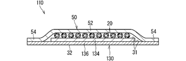
- FIG. 3 is a schematic cross-sectional view showing the wiring member 110 according to the second embodiment.
- the same components as those described above are designated by the same reference numerals and the description thereof will be omitted. The same applies to the following description of each embodiment.
- the first fixing portion 134 and the second fixing portion 136 are provided on the one main surface 31.
- the first fixing portion 134 on the one main surface 31 partially overlaps the second fixing portion 136.
- the first fixing portion 134 is, for example, a sheet-like member formed in an elongated rectangular shape.
- the second fixing portion 136 is a sheet-like member formed in an elongated rectangular shape wider than the first fixing portion 134. Then, the first fixing portion 134 is partially overlapped and fixed on one main surface of the second fixing portion 136.
- the first fixing portion 134 is fixed to the middle portion while avoiding the side edge portion on the one main surface of the second fixing portion 136.
- the first fixing portion 134 appears in the widthwise intermediate portion of the one main surface 31 of the sheet material 130.
- the side edge portion of the one main surface of the second fixing portion 136 appears at the width direction end of the one main surface 31 of the sheet material 130.
- a plurality of linear transmission members 20 are directly fixed to the first fixing portion 134 in a state of being arranged side by side, and the side edge portion of the cover 50 is directly fixed to the side edge portion on one main surface of the second fixing portion 136. ..
- the usage amount of the first fixing portion 134 can be reduced.
- first fixing portion 134 there may be a portion where the first fixing portion 134 is not provided in the intermediate portion in the width direction on one main surface 31 of the sheet material 130. That is, a plurality of narrow first fixing portions 134 may be provided at intervals in the width direction with respect to the second fixing portion 136. In this case, the intermediate portion on one main surface of the second fixing portion 136 appears on one main surface 31 of the sheet material 130. At this time, the width direction middle part of the cover 50 may be directly fixed to the middle part on the one main surface of the second fixing portion 36 that appears on the one main surface 31 of the sheet material 130.
- FIG. 4 is a schematic cross-sectional view showing the wiring member 210 according to the third embodiment.
- the first fixing portion 234 and the second fixing portion 236 are provided on the one main surface 31.
- the first fixing portion 234 and the second fixing portion 236 are provided on the one main surface 31 by folding back a part of the sheet-shaped member constituting the sheet material 230.
- the sheet material 230 includes a laminated portion 40 in which a first layer forming the first fixing portion 234 and a second layer forming the second fixing portion 236 are laminated. A part of the laminated portion 40 is folded back to the one main surface side of the laminated portion 40. Thereby, the sheet material 230 in which the first fixing portion 234 and the second fixing portion 236 are provided on the one main surface 31 is formed.
- the sheet-shaped member before being folded back a sheet-shaped member formed so that the laminated portion 40 spreads uniformly is used. That is, the sheet-like member forming the first layer and the sheet-like member forming the second layer are formed to have the same size, but are laminated so that there is no protruding portion, and the whole is the laminated portion 40. A sheet-shaped member is used.
- the first layer is laminated so as to form one principal surface and the second layer constitutes the other principal surface. Then, the end portion of the laminated portion 40 is folded back to one main surface side so that the first layer is on the inside.
- the first fixing portion 234 appears at the widthwise intermediate portion and the second fixing portion 236 appears at the widthwise end portion.
- the plurality of linear transmission members 20 are directly fixed to the first fixing portion 234 in a lined state, and the side edge portion of the cover 50 is directly fixed to the side edge portion of the one main surface 31 of the second fixing portion 236. There is.
- the folded-back portion 42 in which a part of the laminated portion 40 is folded back is maintained in the folded-back shape by, for example, being directly fixed to the cover 50. Further, for example, the folded-back portion 42 is maintained in the folded-back shape due to the folding tendency.
- the folded-back shape maintaining portion that maintains the folded-back shape may be separately provided in the folded-back portion 42.
- surfaces of the folded-back portion 42 that face each other are directly fixed to each other, or an inclusion such as an adhesive or a double-sided adhesive tape is used. It is also possible to adopt a configuration in which it is adhesively fixed via.
- the folded-back shape maintaining portion a configuration in which both side portions of the folded-back portion 42 that sandwich the fold are sewn with a thread, a configuration in which they are fastened with a stapler, or the like can be adopted.
- the sheet material 230 includes the laminated portion 40 in which the first layer forming the first fixing portion 234 and the second layer forming the second fixing portion 236 are laminated, and a part of the laminated portion 40 is laminated.
- the one main surface 31 of the sheet material 230 is formed by folding back to one main surface side of the portion 40, the sheet-like member formed so that the laminated portion 40 spreads uniformly is folded back to form the sheet material 230.
- the one main surface 31 can be formed.
- FIG. 5 is a schematic cross-sectional view showing the wiring member 310 according to the fourth embodiment.
- the coating 24 of the linear transmission member 20 is directly fixed to the first fixing portion 334 provided on the one main surface 31 of the sheet material 330.
- the cover 350 is directly fixed to the second fixing portion 336 provided on the other main surface 32 of the sheet material 330.
- the shape of the fixing portion 354 of the cover 350 is different from the shape of the fixing portion 54 of the cover 50.
- the fixing portion 354 extends from the edge portion of the main body portion 52 toward the other main surface 32.
- the fixing portion 354 is connected to the main body portion 52, the base end portion 355 that covers the one main surface 31 of the sheet material 330, the tip end portion 356 that covers the other main surface 32 of the sheet material 330, the base end portion 355, and the tip portion.
- the connecting portion 357 is bent from the one main surface 31 side of the sheet material 330 toward the other main surface 32 side.
- the tip portion 356 is directly fixed to the second fixing portion 336 provided on the other main surface 32 of the sheet member.
- one main surface 31 is provided with a first fixing portion 334
- the other main surface 32 is provided with a second fixing portion 336.
- a sheet-shaped member similar to the sheet-shaped member before being folded back in the third embodiment is used as the sheet material 330. That is, as the sheet material 330, a sheet-like member in which a laminated portion in which a first layer forming the first fixing portion 334 and a second layer forming the second fixing portion 336 are laminated uniformly spreads is used as it is. There is. As described above, in this example, as the sheet material 330, the laminated portion 40 in which the first layer forming the first fixing portion 334 and the second layer forming the second fixing portion 336 are laminated is uniformly spread. The shaped member can be used as it is.
- the sheet material 330 a sheet material other than the sheet-shaped member in which the laminated portion 40 uniformly spreads may be adopted.
- the sheet material 30 described in the first embodiment may be used in the reverse direction in the front and back directions.
- the sheet materials 130 and 230 described in the second and third embodiments may be used without changing the front-back direction.
- the tip portion 356 of the fixing portion 354 may be directly fixed to a position avoiding a portion of the second fixing portion 336 provided on the other main surface 32 of the sheet material 330 that overlaps the linear transmission member 20. This is because when the cover 350 and the sheet material 330 are directly fixed, it is not necessary to sandwich the linear transmission member 20 by the pressing members 80 and 82 as shown in FIG.
- the base end portion 355 of the fixing portion 354 may be directly fixed to the one main surface 31 of the sheet material 330, or may not be fixed.
- the base end portion 355 of the fixing portion 354 is also sandwiched by the pressing members 80 and 82, and directly fixed to the sheet material 330. Can be done.
- a portion of the one main surface 31 of the sheet material 330 that faces the base end portion 355 of the fixing portion 354 is the first fixing portion 334.
- the fixing strength is such that the sheet material 330 and the cover 350 are directly fixed on the other main surface 32 of the sheet material 330. It becomes weaker than the fixing strength of the fixed portion (the portion where the second fixing portion 336 and the tip portion 356 are directly fixed).
- the cover 350 of this example is adopted as the sheet material 330 described in the second embodiment as the sheet material 330, the one main surface 31 of the sheet material 130 faces the base end portion 355 of the fixing portion 354.
- the portion is the second fixing portion 336.
- the fixing strength is such that the sheet material 130 and the cover 350 are directly fixed on the other main surface 32 of the sheet material 130.
- the fixing strength of the fixed portion (the portion where the second fixing portion 136 and the tip portion 356 are directly fixed) can be about the same.
- the protruding dimension of the fixing portion 354 in the front and back direction of the body portion 52 of the cover 350 becomes large.
- the base material of the cover 350 is a sheet-like member having high rigidity
- the rigidity of the wiring member 310 is further increased by increasing the protruding dimension of the fixing portion 354 in the front and back directions of the main body portion 52 in the cover 350. Therefore, the shape of the wiring member 310 can be easily maintained.
Landscapes
- Details Of Indoor Wiring (AREA)
- Insulated Conductors (AREA)
- Communication Cables (AREA)
Abstract
線状伝送部材における被覆が直接固定されたシート材に、線状伝送部材における被覆とは異なる材料によって形成されたカバーを良好に付けることができる技術を提供することを目的とする。配線部材は、伝送線本体と前記伝送線本体を覆う被覆とを含む線状伝送部材と、前記線状伝送部材が固定されているシート材と、前記被覆とは別材料によって形成されて、前記シート材とは反対側から前記線状伝送部材を覆い、前記シート材に固定されているカバーと、を備え、前記シート材は、前記被覆が直接固定されている第1固定用部分と、前記第1固定用部分よりも前記カバーと直接固定しやすく前記カバーが直接固定されている第2固定用部分とを含む。
Description
本開示は、配線部材に関する。
特許文献1は、シート状に形成された機能性外装部材と、長手方向に沿った少なくとも一部の領域で前記機能性外装部材に重なるように配設された電線と、を備え、前記電線の絶縁被覆と前記機能性外装部材とが重なる部分の少なくとも一部が溶着されている、ワイヤーハーネスを開示している。
ところで特許文献1に記載のワイヤーハーネスにおけるシート材に、電線の被覆とは異なる材料によって形成されたカバーを付けることが望まれている。
そこで、線状伝送部材における被覆が直接固定されたシート材に、線状伝送部材における被覆とは異なる材料によって形成されたカバーを良好に付けることができる技術を提供することを目的とする。
本開示の配線部材は、伝送線本体と前記伝送線本体を覆う被覆とを含む線状伝送部材と、前記線状伝送部材が固定されているシート材と、前記被覆とは別材料によって形成されて、前記シート材とは反対側から前記線状伝送部材を覆い、前記シート材に固定されているカバーと、を備え、前記シート材は、前記被覆が直接固定されている第1固定用部分と、前記第1固定用部分よりも前記カバーとの直接固定に適し前記カバーが直接固定されている第2固定用部分とを含む、配線部材である。
本開示によれば、線状伝送部材における被覆が直接固定されたシート材に、線状伝送部材における被覆とは異なる材料によって形成されたカバーを良好に付けることができる。
[本開示の実施形態の説明]
最初に本開示の実施態様を列記して説明する。
本開示の配線部材は、次の通りである。
(1)伝送線本体と前記伝送線本体を覆う被覆とを含む線状伝送部材と、前記線状伝送部材が固定されているシート材と、前記被覆とは別材料によって形成されて、前記シート材とは反対側から前記線状伝送部材を覆い、前記シート材に固定されているカバーと、を備え、前記シート材は、前記被覆が直接固定されている第1固定用部分と、前記第1固定用部分よりも前記カバーとの直接固定に適し前記カバーが直接固定されている第2固定用部分とを含む、配線部材である。
シート材において第1固定用部分よりもカバーに直接固定に適する第2固定用部分にカバーが直接固定されていることによって、線状伝送部材における被覆が直接固定されたシート材に、線状伝送部材における被覆とは異なる材料によって形成されたカバーを良好に付けることが可能となる。
ここで線状伝送部材とは、電気又は光等を伝送する線状の部材である。また伝送線本体とは、線状伝送部材において電気又は光等を伝送する部分である。また直接固定とは、相互に固定される2部材のうち少なくとも一方に含まれる樹脂が溶かされることによってくっついて固定される態様である。
(2)前記第2固定用部分には空間が形成され、前記カバーは前記空間の少なくとも一部を埋めるように直接固定されていると良い。空間を埋めることによって生じるアンカー効果によって、第2固定用部分が第1固定用部分よりもカバーと直接固定しやすくなるからである。
(3)前記線状伝送部材は、前記シート材における一方主面に設けられた前記第1固定用部分に直接固定され、前記カバーは、前記シート材における一方主面に設けられた前記第2固定用部分に直接固定されていることが考えられる。この場合、線状伝送部材及びカバーをシート材に対して別の主面に固定せずに済む。
(4)前記一方主面における前記第2固定用部分は、前記第1固定用部分に部分的に重なっていることが考えられる。この場合、第2固定用部分の使用量を少なくできる。
(5)前記一方主面における前記第1固定用部分は、前記第2固定用部分に部分的に重なっていることが考えられる。この場合、第1固定用部分の使用量を少なくできる。
(6)前記シート材は、前記第1固定用部分をなす第1層と、前記第2固定用部分をなす第2層とが積層された積層部を含み、前記積層部の一部が前記積層部の一方の主面側に折り返されて前記シート材における前記一方主面が形成されていることが考えられる。この場合、積層部が一様に広がるように形成されたシート状部材を折り返して、シート材の一方主面を形成することができる。
(7)前記被覆は前記シート材における一方主面に設けられた前記第1固定用部分に直接固定され、前記カバーは、前記一方主面側において前記シート材とは反対側から前記線状伝送部材を覆う本体部と、前記本体部における縁部から前記シート材における他方主面に向けて延出し前記他方主面に設けられた前記第2固定用部分に直接固定されている固定部とを含むことも考えられる。この場合、シート材として、第1固定用部分をなす第1層と、第2固定用部分をなす第2層とが積層された積層部が一様に広がるシート材をそのまま用いることができる。
最初に本開示の実施態様を列記して説明する。
本開示の配線部材は、次の通りである。
(1)伝送線本体と前記伝送線本体を覆う被覆とを含む線状伝送部材と、前記線状伝送部材が固定されているシート材と、前記被覆とは別材料によって形成されて、前記シート材とは反対側から前記線状伝送部材を覆い、前記シート材に固定されているカバーと、を備え、前記シート材は、前記被覆が直接固定されている第1固定用部分と、前記第1固定用部分よりも前記カバーとの直接固定に適し前記カバーが直接固定されている第2固定用部分とを含む、配線部材である。
シート材において第1固定用部分よりもカバーに直接固定に適する第2固定用部分にカバーが直接固定されていることによって、線状伝送部材における被覆が直接固定されたシート材に、線状伝送部材における被覆とは異なる材料によって形成されたカバーを良好に付けることが可能となる。
ここで線状伝送部材とは、電気又は光等を伝送する線状の部材である。また伝送線本体とは、線状伝送部材において電気又は光等を伝送する部分である。また直接固定とは、相互に固定される2部材のうち少なくとも一方に含まれる樹脂が溶かされることによってくっついて固定される態様である。
(2)前記第2固定用部分には空間が形成され、前記カバーは前記空間の少なくとも一部を埋めるように直接固定されていると良い。空間を埋めることによって生じるアンカー効果によって、第2固定用部分が第1固定用部分よりもカバーと直接固定しやすくなるからである。
(3)前記線状伝送部材は、前記シート材における一方主面に設けられた前記第1固定用部分に直接固定され、前記カバーは、前記シート材における一方主面に設けられた前記第2固定用部分に直接固定されていることが考えられる。この場合、線状伝送部材及びカバーをシート材に対して別の主面に固定せずに済む。
(4)前記一方主面における前記第2固定用部分は、前記第1固定用部分に部分的に重なっていることが考えられる。この場合、第2固定用部分の使用量を少なくできる。
(5)前記一方主面における前記第1固定用部分は、前記第2固定用部分に部分的に重なっていることが考えられる。この場合、第1固定用部分の使用量を少なくできる。
(6)前記シート材は、前記第1固定用部分をなす第1層と、前記第2固定用部分をなす第2層とが積層された積層部を含み、前記積層部の一部が前記積層部の一方の主面側に折り返されて前記シート材における前記一方主面が形成されていることが考えられる。この場合、積層部が一様に広がるように形成されたシート状部材を折り返して、シート材の一方主面を形成することができる。
(7)前記被覆は前記シート材における一方主面に設けられた前記第1固定用部分に直接固定され、前記カバーは、前記一方主面側において前記シート材とは反対側から前記線状伝送部材を覆う本体部と、前記本体部における縁部から前記シート材における他方主面に向けて延出し前記他方主面に設けられた前記第2固定用部分に直接固定されている固定部とを含むことも考えられる。この場合、シート材として、第1固定用部分をなす第1層と、第2固定用部分をなす第2層とが積層された積層部が一様に広がるシート材をそのまま用いることができる。
[本開示の実施形態の詳細]
本開示の配線部材の具体例を、以下に図面を参照しつつ説明する。なお、本発明はこれらの例示に限定されるものではなく、請求の範囲によって示され、請求の範囲と均等の意味および範囲内でのすべての変更が含まれることが意図される。
本開示の配線部材の具体例を、以下に図面を参照しつつ説明する。なお、本発明はこれらの例示に限定されるものではなく、請求の範囲によって示され、請求の範囲と均等の意味および範囲内でのすべての変更が含まれることが意図される。
[実施形態1]
以下、実施形態1に係る配線部材について説明する。図1は、実施形態1にかかる配線部材10を示す概略断面図である。図2は図1の部分拡大図である。
以下、実施形態1に係る配線部材について説明する。図1は、実施形態1にかかる配線部材10を示す概略断面図である。図2は図1の部分拡大図である。
配線部材10は、線状伝送部材20と、線状伝送部材20が固定されたシート材30と、シート材30に固定されたカバー50とを備える。
線状伝送部材20は、電気又は光等を伝送する線状の部材であればよい。線状伝送部材20は、伝送線本体22と伝送線本体22を覆う被覆24とを含む。例えば、線状伝送部材20は、芯線と芯線の周囲の被覆とを有する一般電線であってもよいし、シールド線、エナメル線、ニクロム線、光ファイバ等であってもよい。例えば、線状伝送部材20が一般電線である場合、一般電線における芯線が伝送線本体22に相当し、一般電線における芯線を覆う絶縁被覆が、被覆24に相当する。一般電線における絶縁被覆は、例えば、PVC(ポリ塩化ビニル)、PE(ポリエチレン)などの樹脂材料が芯線の周囲に押出成形されるなどして形成される。電気を伝送する線状伝送部材20としては、各種信号線、各種電力線であってもよい。電気を伝送する線状伝送部材20は、信号又は電力を空間に対して送る又は空間から受けるアンテナ、コイル等として用いられてもよい。
ここでは、複数本(図1では11本)の線状伝送部材20が並列状態でシート材30に固定されている。線状伝送部材20は、1本でもよいし、複数本であってもよい。線状伝送部材20は、シート材30上で曲った経路で延びるように固定されていてもよい。複数の線状伝送部材20は、途中で分岐するようにシート材30に固定されていてもよい。複数の線状伝送部材20は、途中で交差するようにシート材30に固定されていてもよい。
シート材30は、主面上に線状伝送部材20が固定されるシート状の部材である。シート材30の主面上に線状伝送部材20が固定されることによって、当該線状伝送部材20が主面において所定の経路に沿って保持される。シート材30は、容易に曲げ可能な柔軟性を有していてもよいし、一定の形状を保つことができる程度の剛性を有する部材であってもよい。
シート材30は、第1固定用部分34と第2固定用部分36とを含む。第1固定用部分34に線状伝送部材20の被覆24が直接固定されることによって、線状伝送部材20がシート材30に固定されている。また第2固定用部分36にカバー50が直接固定されることによって、カバー50がシート材30に固定されている。
直接固定とは、固定される2部材が、別に設けられた接着剤等を介さずに直接くっついて固定されているものである。直接固定では、例えば固定される2部材のうち一方に含まれる樹脂のみが溶かされることによってくっついて固定されることも考えられるし、固定される2部材のうち両方に含まれる樹脂が溶かされることによってくっついて固定されることも考えられる。前者の場合、溶けた方の樹脂が他方の外面にくっついて固化した状態となり、比較的はっきりした界面が形成されることがある。後者の場合、両方の樹脂が混ざり合ってはっきりした界面が形成されないことがある。特に、2部材に含まれる樹脂が、同じ樹脂材料など、相溶し易い樹脂である場合などに、両方の樹脂が混ざり合ってはっきりした界面が形成されないことがある。
直接固定の状態を形成する手段は特に限定されるものではなく、溶着、融着、溶接等の公知の手段を含む各種手段を用いることができる。例えば、溶着によって熱による直接固定の状態を形成する場合、超音波溶着、加熱加圧溶着、熱風溶着、高周波溶着など種々の溶着手段を採用することができる。またこれらの手段によって直接固定の状態が形成されると、2部材は、その手段による直接固定の状態とされる。具体的には、例えば、超音波溶着によって直接固定の状態が形成されると、2部材は、超音波溶着による直接固定の状態とされる。溶着によって熱による直接固定の状態を形成した部分を溶着部、このうち、超音波溶着による固定部分を超音波溶着部、加熱加圧溶着による固定部分を加熱加圧溶着部等と称してもよい。
本例では、第1固定用部分34及び第2固定用部分36がシート材30における一方主面31に設けられている。そして線状伝送部材20は、シート材30における一方主面31に設けられた第1固定用部分34に直接固定されている。またカバー50は、シート材30における一方主面31に設けられた第2固定用部分36に直接固定されている。
ここではシート材30は、第1固定用部分34と、第2固定用部分36とが積層された構成とされている。シート材30における一方主面31における第2固定用部分36は、第1固定用部分34に部分的に重なって形成されている。第1固定用部分34は、シート状の部材である。例えば第1固定用部分34は、細長い方形状に形成されている。この第1固定用部分34の一方主面31に線状伝送部材20が直接固定される。第2固定用部分36は、第1固定用部分34よりも細幅に形成されたシート状の部材である。ここでは、第1固定用部分34の一方主面において、線状伝送部材20が固定される部分を避けた位置に第2固定用部分36が重ね合せ状態で固定される。この第2固定用部分36の一方主面にカバー50が直接固定される。
第1固定用部分34と第2固定用部分36との固定態様は特に限定されるものではなく、直接固定であってもよいし、接着剤、両面粘着テープなどの介在物を介した接着固定であってもよい。図2に示す例では、第1固定用部分34と第2固定用部分36とが直接固定されている。
カバー50は、被覆24とは別材料によって形成されている。カバー50は、シート材30とは反対側から線状伝送部材20を覆う。カバー50は、本体部52と固定部54とを含む。本体部52は、シート材30とは反対側から線状伝送部材20を覆う部分である。固定部54は、本体部52から延出しシート材30に直接固定されている部分である。ここでは、本体部52は、複数の線状伝送部材20をまとめて覆っている。固定部54は、本体部52における縁部から延出し、シート材30における縁部においてシート材30と直接固定されている。ここではカバー50はシート材30よりも高剛性を有するように形成されている。カバー50は、配線部材10の形状をなるべく維持可能である。
第1固定用部分34に線状伝送部材20が直接固定されることから、第1固定用部分34は、第2固定用部分36と比較して線状伝送部材20における被覆24との直接固定に適した部材とされている。
第1固定用部分34が第2固定用部分36と比較して線状伝送部材20との直接固定に適しているとは、次のように捉えることができる。すなわち、同じ構成を有する線状伝送部材20を同じ条件のもとで第1固定用部分34及び第2固定用部分36に固定した場合に、第1固定用部分34に対する線状伝送部材20の固定力が、第2固定用部分36に対する線状伝送部材20の固定力よりも大きくなることである。本例のように直接固定が採用される場合には、被覆24における樹脂表面と第1固定用部分34における樹脂表面との少なくとも一方が溶けて固化して両者がくっついた場合の固着力が、被覆24における樹脂表面と第2固定用部分36における樹脂表面との少なくとも一方が溶けて固化して両者がくっついた場合の固着力よりも大きいと考えてもよい。
上記条件を満たすものであれば、第1固定用部分34を構成する材料は特に限定されるものではなく、被覆24を構成する材料との関係で選定されればよい。被覆24と第1固定用部分34とは同じ樹脂又は同系の樹脂を材料としているとよい。例えば、被覆24がPVCを主成分とする樹脂によって形成されている場合、第1固定用部分34もPVCを主成分とする樹脂によって形成されるとよい。
第1固定用部分34は、内部が一様に埋った充実シート状の部材とされている。これは、第1固定用部分34と線状伝送部材20との直接固定状態を作成するときに両者の接触面積が小さくなっても、固着力を高められるようにするためである。特にここでは、線状伝送部材20の横断面が円形であることによって線状伝送部材20と第1固定用部分34との接触面積が小さくなりやすい。
第1固定用部分34として、線状伝送部材20の固定に適したものを採用すると、カバー50との固定に不向きとなる恐れがある。そこで、第2固定用部分36によって、カバー50と良好に固定できるようにする。つまり、第2固定用部分36は、第1固定用部分34と比較してカバー50との直接固定に適した部材とされている。
第2固定用部分36が第1固定用部分34と比較してカバー50との直接固定に適しているとは、次のように捉えることができる。すなわち、同じ構成を有するカバー50を同じ条件のもとで第1固定用部分34及び第2固定用部分36に固定した場合に、第2固定用部分36に対するカバー50の固定力が、第1固定用部分34に対するカバー50の固定力よりも大きくなることである。本例のように直接固定が採用される場合には、カバー50における樹脂表面と第2固定用部分36における樹脂表面との少なくとも一方が溶けて固化して両者がくっついた場合の固着力が、カバー50における樹脂表面と第1固定用部分34における樹脂表面との少なくとも一方が溶けて固化して両者がくっついた場合の固着力よりも大きいと考えてもよい。
上記条件を満たすものであれば、第2固定用部分36を構成する材料、構造は特に限定されるものではなく、カバー50を構成する材料、構造との関係で選定されればよい。ここでは第2固定用部分36に空間38が形成されていることによって、第2固定用部分36は、第1固定用部分34よりもカバー50との直接固定に適する。すなわちカバー50は空間38の少なくとも一部を埋めるように直接固定されている。これによりカバー50が第2固定用部分36に直接固定された状態で、カバー50と第2固定用部分36との間にアンカー効果が生じる。換言すれば、カバー50と第2固定用部分36とは、主としてアンカー効果という物理的作用によって固定されるため、第2固定用部分36として、カバー50への化学的な固着力等を考慮せずに済み、選択できる材料の幅が広がる。
第2固定用部分36が第1固定用部分34よりもカバー50との直接固定に適するものとして、主としてアンカー効果などの物理的作用を利用するものではなく、水素結合、ファンデルワールス力などの化学的作用を主として利用するものでもよい。例えば、第2固定用部分36がカバー50と同じ樹脂材料、又は同系の樹脂材料によって構成され、第1固定用部分34がカバー50との接着性の低い異系の樹脂材料によって構成されていることによって、化学的作用によって第2固定用部分36が第1固定用部分34よりもカバー50との直接固定に適するものであると考えてよい。
第2固定用部分36における空間38の態様は特に限定されるものではない。例えば、第2固定用部分36をなす部材が不織布、樹脂発泡体など多孔質である部材であることによって、多孔質な部分の各孔が空間38とされていてもよい。また例えば第2固定用部分36をなす部材が網状の部材であることによって網目が空間38とされていてもよい。また例えば第2固定用部分36をなす部材が編地、織地などであることによって編地、織地を構成する糸の間が空間38とされていてもよい。また例えば充実シート状の第2固定用部分36の表面に溝、凹み、切込み等が形成されたり、第2固定用部分36を貫通する孔が形成されたりして空間38とされていてもよい。そしてこの空間38の少なくとも一部を、カバー50を構成する樹脂が埋めることによって、カバー50と第2固定用部分36との間にアンカー効果が生じ、カバー50と第2固定用部分36とがしっかりと固定される。このときカバー50と第2固定用部分36とは、1本の線状伝送部材20が第1固定用部分34と接触する領域よりも大きい領域で面接触していると良い。
第2固定用部分36が空間38を有する場合、第2固定用部分36を構成する材料は特に限定されるものではない。直接固定時にカバー50の溶けた材料が空間38に入り込むまで、空間38の少なくとも一部が残存できれば良い。例えば、第2固定用部分36を形成する材料の融点が、カバー50の材料の融点と同程度かそれよりも高いと良い。これにより、第2固定用部分36がカバー50よりも先に溶けて第2固定用部分36における空間38が第2固定用部分36によって埋められてすべてなくなってしまうことを抑制できる。第2固定用部分36を構成する材料の融点が、カバー50を構成する材料の融点と同程度かそれよりも高いことは必須ではない。第2固定用部分36を構成する材料の融点が、カバー50を構成する材料の融点よりも低い場合でも、カバー50と第2固定用部分36とが直接固定される際、第2固定用部分36が重点的に加熱されるなどすることによって、直接固定時にカバー50の溶けた材料が空間38に入り込むまで、空間38の少なくとも一部が残存できる。
第2固定用部分36は、例えば、PET(ポリエチレンテレフタレート)を材料として形成されて、カバー50がナイロン、PET、PP(ポリプロピレン)などを材料としていることが考えられる。
カバー50は、充実シート状部材、又は独立気泡型の発泡体などであり、シート材30よりも硬く形成されて高剛性とされている。例えばカバー50は、ナイロン、PET、PPなどの材料によって形成された充実シート状部材、又は独立気泡型の発泡体であり、シート材30は軟質PVCを材料とした充実シート状部材とPETを材料とした不織布とが積層された柔らかい部材である。
第2固定用部分36にカバー50が固定される前に、第1固定用部分34と第2固定用部分36とが固定されると良い。第1固定用部分34と第2固定用部分36とは、直接固定されていてもよいし、接着剤、両面粘着テープなどの介在物によって貼り合わされていてもよい。図2に示す例では、充実シート状の第1固定用部分34が、不織布である第2固定用部分36における空間38の一部(第1固定用部分34側の空間38)を埋めることによって、第1固定用部分34と第2固定用部分36とが直接固定されている。このとき、第1固定用部分34と第2固定用部分36とが固定された状態で、第2固定用部分36において、第1固定用部分34側とは反対側に空間38が残った状態とされる。そしてこの残存する空間38を、カバー50を構成する樹脂が埋めることによって、カバー50と第2固定用部分36とが直接固定される。
カバー50と第2固定用部分36とは、加圧部材80、82に挟持されることによって加圧されつつ熱が加えられて直接固定される。この加圧部材80、82の少なくとも一方が加熱部材であってもよい。カバー50と第2固定用部分36とが加圧部材80、82によって挟持される際、第1固定用部分34も併せて挟持される。
配線部材10によると、シート材30において第1固定用部分34よりもカバー50に直接固定しやすい第2固定用部分36にカバー50が直接固定されていることによって、線状伝送部材20における被覆24が直接固定されたシート材30に、線状伝送部材20における被覆24とは異なる材料によって形成されたカバー50を良好に付けることが可能となる。
第2固定用部分36には空間38が形成され、カバー50は空間38を埋めるように直接固定されているため、空間38を埋めることによって生じるアンカー効果によって、第2固定用部分36が第1固定用部分34よりもカバー50と直接固定しやすくなる。
線状伝送部材20は、シート材30における一方主面31に設けられた第1固定用部分34に直接固定され、カバー50は、シート材30における一方主面31に設けられた第2固定用部分36に直接固定されているため、線状伝送部材20及びカバー50をシート材30に対して別の主面に固定せずに済む。一方主面31における第2固定用部分36は、第1固定用部分34に部分的に重なって形成されているため、第2固定用部分36の使用量を少なくできる。
[実施形態2]
実施形態2に係る配線部材について説明する。図3は実施形態2にかかる配線部材110を示す概略断面図である。なお、本実施形態の説明において、これまで説明したものと同様構成要素については同一符号を付してその説明を省略する。以下の各実施形態の説明においても同様である。
実施形態2に係る配線部材について説明する。図3は実施形態2にかかる配線部材110を示す概略断面図である。なお、本実施形態の説明において、これまで説明したものと同様構成要素については同一符号を付してその説明を省略する。以下の各実施形態の説明においても同様である。
本例でもシート材130において、一方主面31に第1固定用部分134及び第2固定用部分136が設けられている。本例においては、一方主面31における第1固定用部分134は、第2固定用部分136に部分的に重なっている。具体的には、第1固定用部分134は、例えば、細長い方形状に形成されたシート状部材である。第2固定用部分136は、第1固定用部分134よりも幅広の細長い方形状に形成されたシート状部材である。そして、第1固定用部分134が第2固定用部分136の一方主面に部分的に重ねられて固定される。
図3に示す例では、第1固定用部分134は、第2固定用部分136の一方主面において側縁部を避けて中間部に固定されている。第1固定用部分134が、シート材130の一方主面31において幅方向中間部に現れている。第2固定用部分136の一方主面における側縁部が、シート材130における一方主面31において幅方向端部に現れている。第1固定用部分134に複数の線状伝送部材20が並んだ状態で直接固定され、第2固定用部分136の一方主面における側縁部にカバー50の側縁部が直接固定されている。
このように一方主面31における第1固定用部分134が、第2固定用部分136に部分的に重なっていると、第1固定用部分134の使用量を少なくできる。
実施形態2に示す例において、シート材130の一方主面31における幅方向中間部に第1固定用部分134が設けられない部分が存在していてもよい。つまり、細幅の複数の第1固定用部分134が第2固定用部分136に対して幅方向に間隔をあけつつ設けられていてもおい。この場合、第2固定用部分136の一方主面における中間部が、シート材130の一方主面31に現れる。このとき、カバー50の幅方向中間部が、シート材130の一方主面31に現れた第2固定用部分36の一方主面における中間部に直接固定されていても良い。
[実施形態3]
実施形態3に係る配線部材について説明する。図4は実施形態3にかかる配線部材210を示す概略断面図である。
実施形態3に係る配線部材について説明する。図4は実施形態3にかかる配線部材210を示す概略断面図である。
本例でもシート材230において、一方主面31に第1固定用部分234及び第2固定用部分236が設けられている。本例においては、シート材230を構成するシート状部材の一部が折り返されることによって、一方主面31に第1固定用部分234及び第2固定用部分236が設けられている。
具体的には、シート材230は、第1固定用部分234をなす第1層と、第2固定用部分236をなす第2層とが積層された積層部40を含む。積層部40の一部が積層部40の一方の主面側に折り返されている。これにより、一方主面31に第1固定用部分234及び第2固定用部分236が設けられたシート材230が形成されている。
ここでは、折り返される前のシート状部材として、積層部40が一様に広がるように形成されたシート状部材が用いられている。すなわち、第1層をなすシート状部材と、第2層をなすシート状部材とが同様の大きさに形成されつつ、相互にはみ出し部分がないように積層されて全体が積層部40とされたシート状部材が用いられている。
ここでは積層部40において、第1層が一方主面をなし、第2層が他方主面をなすように積層されている。そして積層部40の端部が第1層を内側とするように一方の主面側に折り返されている。これによりシート材230の一方主面31において、幅方向中間部に第1固定用部分234が現れ、幅方向端部に第2固定用部分236が現れている。第1固定用部分234に複数の線状伝送部材20が並んだ状態で直接固定され、第2固定用部分236の一方主面31における側縁部にカバー50の側縁部が直接固定されている。
積層部40の一部が折り返された折り返し部42は、例えばカバー50と直接固定されることによって、折り返された形状に維持されている。また例えば折り返し部42は、折癖によって、折り返された形状に維持されている。折り返し部42に、折り返し形状を維持する折り返し形状維持部が別途設けられていてもよい。係る折り返し形状維持部として、例えば、折り返し部42において相互に対向する面(図3に示す例では第1層の主面)同士が、直接固定されたり、接着剤、両面粘着テープなどの介在物を介して接着固定されたりする構成を採用することができる。また例えば、折り返し形状維持部として、折り返し部42における折り目を挟んだ両側部分が糸などによって縫われた構成、ステープラなどによって留められた構成などを採用することができる。
このようにシート材230が第1固定用部分234をなす第1層と、第2固定用部分236をなす第2層とが積層された積層部40を含み、積層部40の一部が積層部40の一方の主面側に折り返されてシート材230における一方主面31が形成されていると、積層部40が一様に広がるように形成されたシート状部材を折り返して、シート材230の一方主面31を形成することができる。
[実施形態4]
実施形態4に係る配線部材について説明する。図5は実施形態4にかかる配線部材310を示す概略断面図である。
実施形態4に係る配線部材について説明する。図5は実施形態4にかかる配線部材310を示す概略断面図である。
本例では、線状伝送部材20の被覆24がシート材330における一方主面31に設けられた第1固定用部分334に直接固定されている。またカバー350が、シート材330における他方主面32に設けられた第2固定用部分336に直接固定されている。このときカバー350における固定部354の形状が、上記カバー50における固定部54の形状とは異なる。固定部354は、本体部52における縁部から他方主面32に向けて延出している。このとき固定部354は、本体部52とつながりシート材330における一方主面31を覆う基端部355と、シート材330における他方主面32を覆う先端部356と、基端部355及び先端部356を連結する連結部357とを有している。連結部357は、シート材330における一方主面31側から他方主面32側に向けて曲がっている。そして、先端部356が、シート部材における他方主面32に設けられた第2固定用部分336に直接固定されている。
シート材330において一方主面31に第1固定用部分334が設けられ、他方主面32に第2固定用部分336が設けられている。係るシート材330は、実施形態3において折り返される前のシート状部材と同様のシート状部材が用いられている。すなわち、シート材330として第1固定用部分334をなす第1層と、第2固定用部分336をなす第2層とが積層された積層部が一様に広がるシート状部材がそのまま用いられている。このように本例では、シート材330として、第1固定用部分334をなす第1層と、第2固定用部分336をなす第2層とが積層された積層部40が一様に広がるシート状部材をそのまま用いることができる。
シート材330として積層部40が一様に広がるシート状部材以外のシート材が採用されてもよい。例えば実施形態1において説明したシート材30が、表裏方向に逆向きに用いられていてもよい。また例えば実施形態2、実施形態3において説明したシート材130、230が、表裏方向の向きをそのままに用いられていてもよい。
固定部354における先端部356は、シート材330における他方主面32に設けられた第2固定用部分336のうち線状伝送部材20と重なる部分を避けた位置に直接固定されると良い。カバー350とシート材330とを直接固定する際、図5に示すように加圧部材80、82によって線状伝送部材20を挟持せずに済むからである。
固定部354における基端部355は、シート材330における一方主面31と直接固定されている場合もあり得るし、されていない場合もあり得る。例えばカバー350とシート材330とが直接固定される際、図5に示すように、加圧部材80、82によって固定部354における基端部355も併せて挟持されて、シート材330と直接固定されうる。
図5に示す例では、シート材330における一方主面31において、固定部354における基端部355と対向する部分は、第1固定用部分334である。この場合、シート材330における一方主面31においてシート材330とカバー350とが直接固定されている場合、その固定強度は、シート材330における他方主面32においてシート材330とカバー350とが直接固定されている部分(第2固定用部分336と先端部356とが直接固定されている部分)の固定強度よりも弱くなる。シート材330として実施形態2で説明したシート材130に対して本例のようなカバー350が採用された場合、シート材130における一方主面31において、固定部354における基端部355と対向する部分が第2固定用部分336である。この場合、シート材130における一方主面31においてシート材130とカバー350とが直接固定されている場合、その固定強度は、シート材130における他方主面32においてシート材130とカバー350とが直接固定されている部分(第2固定用部分136と先端部356とが直接固定されている部分)の固定強度と同程度になり得る。
本例のようにカバー350における固定部354がシート材330における他方主面32に固定されていると、カバー350において本体部52の表裏方向への固定部354の突出寸法が大きくなる。このとき、カバー350の基材が高剛性を有するシート状部材であると、カバー350において本体部52の表裏方向への固定部354の突出寸法が大きくなることによって、配線部材310の剛性をより高めることができ、配線部材310の形状を維持しやすくなる。
なお、上記各実施形態及び各変形例で説明した各構成は、相互に矛盾しない限り適宜組み合わせることができる。
10、110、210、310 配線部材
20 線状伝送部材
22 伝送線本体
24 被覆
30、130、230、330 シート材
31 一方主面
32 他方主面
34、134、234、334 第1固定用部分
36、136、236、336 第2固定用部分
37 繊維
38 空間
40 積層部
42 折り返し部
50、350 カバー
52 本体部
54、354 固定部
355 基端部
356 先端部
357 連結部
80、82 加圧部材
20 線状伝送部材
22 伝送線本体
24 被覆
30、130、230、330 シート材
31 一方主面
32 他方主面
34、134、234、334 第1固定用部分
36、136、236、336 第2固定用部分
37 繊維
38 空間
40 積層部
42 折り返し部
50、350 カバー
52 本体部
54、354 固定部
355 基端部
356 先端部
357 連結部
80、82 加圧部材
Claims (7)
- 伝送線本体と前記伝送線本体を覆う被覆とを含む線状伝送部材と、
前記線状伝送部材が固定されているシート材と、
前記被覆とは別材料によって形成されて、前記シート材とは反対側から前記線状伝送部材を覆い、前記シート材に固定されているカバーと、
を備え、
前記シート材は、前記被覆が直接固定されている第1固定用部分と、前記第1固定用部分よりも前記カバーとの直接固定に適し前記カバーが直接固定されている第2固定用部分とを含む、配線部材。 - 前記第2固定用部分には空間が形成され、
前記カバーは前記空間の少なくとも一部を埋めるように直接固定されている、請求項1に記載の配線部材。 - 前記線状伝送部材は、前記シート材における一方主面に設けられた前記第1固定用部分に直接固定され、
前記カバーは、前記シート材における一方主面に設けられた前記第2固定用部分に直接固定されている、請求項1又は請求項2に記載の配線部材。 - 前記一方主面における前記第2固定用部分は、前記第1固定用部分に部分的に重なっている、請求項3に記載の配線部材。
- 前記一方主面における前記第1固定用部分は、前記第2固定用部分に部分的に重なっている、請求項3に記載の配線部材。
- 前記シート材は、前記第1固定用部分をなす第1層と、前記第2固定用部分をなす第2層とが積層された積層部を含み、前記積層部の一部が前記積層部の一方の主面側に折り返されて前記シート材における前記一方主面が形成されている、請求項3に記載の配線部材。
- 前記被覆は前記シート材における一方主面に設けられた前記第1固定用部分に直接固定され、
前記カバーは、前記一方主面側において前記シート材とは反対側から前記線状伝送部材を覆う本体部と、前記本体部における縁部から前記シート材における他方主面に向けて延出し前記他方主面に設けられた前記第2固定用部分に直接固定されている固定部とを含む、請求項1又は請求項2に記載の配線部材。
Priority Applications (5)
| Application Number | Priority Date | Filing Date | Title |
|---|---|---|---|
| DE112019006980.2T DE112019006980T5 (de) | 2019-03-06 | 2019-03-06 | Verkabelungselement |
| JP2019536233A JP6579297B1 (ja) | 2019-03-06 | 2019-03-06 | 配線部材 |
| PCT/JP2019/008868 WO2020179017A1 (ja) | 2019-03-06 | 2019-03-06 | 配線部材 |
| US17/431,580 US12014846B2 (en) | 2019-03-06 | 2019-03-06 | Wiring member |
| CN201980093307.1A CN113544796B (zh) | 2019-03-06 | 2019-03-06 | 配线部件 |
Applications Claiming Priority (1)
| Application Number | Priority Date | Filing Date | Title |
|---|---|---|---|
| PCT/JP2019/008868 WO2020179017A1 (ja) | 2019-03-06 | 2019-03-06 | 配線部材 |
Publications (1)
| Publication Number | Publication Date |
|---|---|
| WO2020179017A1 true WO2020179017A1 (ja) | 2020-09-10 |
Family
ID=68053631
Family Applications (1)
| Application Number | Title | Priority Date | Filing Date |
|---|---|---|---|
| PCT/JP2019/008868 Ceased WO2020179017A1 (ja) | 2019-03-06 | 2019-03-06 | 配線部材 |
Country Status (5)
| Country | Link |
|---|---|
| US (1) | US12014846B2 (ja) |
| JP (1) | JP6579297B1 (ja) |
| CN (1) | CN113544796B (ja) |
| DE (1) | DE112019006980T5 (ja) |
| WO (1) | WO2020179017A1 (ja) |
Cited By (2)
| Publication number | Priority date | Publication date | Assignee | Title |
|---|---|---|---|---|
| WO2023021850A1 (ja) * | 2021-08-20 | 2023-02-23 | 株式会社オートネットワーク技術研究所 | 配線部材付き被着体 |
| JP2024157242A (ja) * | 2023-04-25 | 2024-11-07 | 矢崎総業株式会社 | ワイヤハーネス及びワイヤハーネスの製造方法 |
Families Citing this family (5)
| Publication number | Priority date | Publication date | Assignee | Title |
|---|---|---|---|---|
| JP7211331B2 (ja) * | 2019-10-23 | 2023-01-24 | 株式会社オートネットワーク技術研究所 | 配線部材 |
| JP7184020B2 (ja) * | 2019-11-14 | 2022-12-06 | 住友電装株式会社 | 配線部材 |
| JP7491027B2 (ja) * | 2020-04-06 | 2024-05-28 | 株式会社オートネットワーク技術研究所 | 配線部材 |
| JP7639439B2 (ja) * | 2021-03-23 | 2025-03-05 | 株式会社オートネットワーク技術研究所 | 配線部材付き被着体 |
| JP7600900B2 (ja) * | 2021-06-30 | 2024-12-17 | 株式会社オートネットワーク技術研究所 | 配線部材 |
Citations (3)
| Publication number | Priority date | Publication date | Assignee | Title |
|---|---|---|---|---|
| JPH07113313A (ja) * | 1993-10-18 | 1995-05-02 | Matsushita Electric Works Ltd | 床配線システム用床材 |
| JP2014087191A (ja) * | 2012-10-25 | 2014-05-12 | Auto Network Gijutsu Kenkyusho:Kk | ワイヤハーネス |
| JP2019004679A (ja) * | 2017-06-14 | 2019-01-10 | 株式会社オートネットワーク技術研究所 | 支持部材付ワイヤーハーネスおよびワイヤーハーネスの支持構造 |
Family Cites Families (15)
| Publication number | Priority date | Publication date | Assignee | Title |
|---|---|---|---|---|
| JPS6224504A (ja) | 1985-07-24 | 1987-02-02 | 日本電信電話株式会社 | フレキシブルケ−ブルおよびフレキシブルケ−ブル用端子付コネクタ |
| JPH10188682A (ja) * | 1996-12-27 | 1998-07-21 | Yazaki Corp | ワイヤーハーネス及びその製造方法 |
| JP3752973B2 (ja) | 2000-07-11 | 2006-03-08 | 住友電装株式会社 | フラットケーブルの製造方法及びフラットケーブル |
| JP2003322731A (ja) * | 2002-04-30 | 2003-11-14 | Nitto Denko Corp | 配線シート用カバーシート、及びその製造方法 |
| JP2004146109A (ja) | 2002-10-22 | 2004-05-20 | Hitachi Cable Ltd | 耐熱・耐屈曲フレキシブルフラットケーブル及びその製造方法 |
| JP4374229B2 (ja) | 2003-10-01 | 2009-12-02 | 矢崎総業株式会社 | フラットシールドケーブルの製造方法 |
| JP2007173056A (ja) * | 2005-12-22 | 2007-07-05 | Toshiba Corp | ハーネスおよび電子機器 |
| CN102884592B (zh) * | 2010-08-31 | 2017-12-26 | 3M创新有限公司 | 具有电介质间距的屏蔽电缆 |
| CN103608873B (zh) * | 2011-06-07 | 2016-12-14 | 3M创新有限公司 | 嵌套式屏蔽带状电缆 |
| JP5984341B2 (ja) | 2011-06-07 | 2016-09-06 | 矢崎総業株式会社 | ワイヤハーネス |
| JP2013005623A (ja) | 2011-06-17 | 2013-01-07 | Auto Network Gijutsu Kenkyusho:Kk | ワイヤーハーネス用保護材料及びワイヤーハーネス |
| JP5786782B2 (ja) * | 2012-03-28 | 2015-09-30 | 株式会社オートネットワーク技術研究所 | ワイヤーハーネス保護材及びワイヤーハーネス |
| JP5884695B2 (ja) * | 2012-09-26 | 2016-03-15 | 住友電装株式会社 | ワイヤーハーネス、ワイヤーハーネスの製造方法及び保護部材 |
| JP6493186B2 (ja) * | 2015-12-07 | 2019-04-03 | 住友電装株式会社 | プロテクタ |
| JP6497420B2 (ja) | 2017-02-23 | 2019-04-10 | 株式会社オートネットワーク技術研究所 | ワイヤーハーネス |
-
2019
- 2019-03-06 US US17/431,580 patent/US12014846B2/en active Active
- 2019-03-06 JP JP2019536233A patent/JP6579297B1/ja active Active
- 2019-03-06 WO PCT/JP2019/008868 patent/WO2020179017A1/ja not_active Ceased
- 2019-03-06 CN CN201980093307.1A patent/CN113544796B/zh active Active
- 2019-03-06 DE DE112019006980.2T patent/DE112019006980T5/de active Pending
Patent Citations (3)
| Publication number | Priority date | Publication date | Assignee | Title |
|---|---|---|---|---|
| JPH07113313A (ja) * | 1993-10-18 | 1995-05-02 | Matsushita Electric Works Ltd | 床配線システム用床材 |
| JP2014087191A (ja) * | 2012-10-25 | 2014-05-12 | Auto Network Gijutsu Kenkyusho:Kk | ワイヤハーネス |
| JP2019004679A (ja) * | 2017-06-14 | 2019-01-10 | 株式会社オートネットワーク技術研究所 | 支持部材付ワイヤーハーネスおよびワイヤーハーネスの支持構造 |
Cited By (5)
| Publication number | Priority date | Publication date | Assignee | Title |
|---|---|---|---|---|
| WO2023021850A1 (ja) * | 2021-08-20 | 2023-02-23 | 株式会社オートネットワーク技術研究所 | 配線部材付き被着体 |
| JP2023028810A (ja) * | 2021-08-20 | 2023-03-03 | 株式会社オートネットワーク技術研究所 | 配線部材付き被着体 |
| JP7655145B2 (ja) | 2021-08-20 | 2025-04-02 | 株式会社オートネットワーク技術研究所 | 配線部材付き被着体 |
| JP2024157242A (ja) * | 2023-04-25 | 2024-11-07 | 矢崎総業株式会社 | ワイヤハーネス及びワイヤハーネスの製造方法 |
| JP7779875B2 (ja) | 2023-04-25 | 2025-12-03 | 矢崎総業株式会社 | ワイヤハーネス及びワイヤハーネスの製造方法 |
Also Published As
| Publication number | Publication date |
|---|---|
| JP6579297B1 (ja) | 2019-09-25 |
| CN113544796B (zh) | 2022-10-14 |
| US12014846B2 (en) | 2024-06-18 |
| CN113544796A (zh) | 2021-10-22 |
| DE112019006980T5 (de) | 2021-11-25 |
| JPWO2020179017A1 (ja) | 2021-03-11 |
| US20220139594A1 (en) | 2022-05-05 |
Similar Documents
| Publication | Publication Date | Title |
|---|---|---|
| WO2020179017A1 (ja) | 配線部材 | |
| JP7168006B2 (ja) | 配線部材及び配線部材の配設構造 | |
| JP6590134B1 (ja) | 固定部材付き配線部材 | |
| JP6669209B2 (ja) | 配線部材 | |
| JP7327097B2 (ja) | 配線部材 | |
| JP7275999B2 (ja) | 配線部材 | |
| JP7658197B2 (ja) | 配線部材 | |
| US12057246B2 (en) | Wiring member to be fixed to adherend by double-sided adhesive member | |
| JP2014068521A (ja) | ワイヤーハーネス | |
| JP2023017928A (ja) | 配線部材 | |
| JPWO2020178998A1 (ja) | 固定部材付き配線部材及び配線部材の固定構造 | |
| JP5962387B2 (ja) | ワイヤーハーネス及びワイヤーハーネスの製造方法 | |
| JP7160059B2 (ja) | 配線部材の固定構造 | |
| JP7184019B2 (ja) | 配線部材 | |
| JP7632505B2 (ja) | 積層シート | |
| JP6784336B1 (ja) | 配線部材 | |
| CN117836873A (zh) | 带配线构件的被粘物 | |
| WO2014175047A1 (ja) | ワイヤーハーネスの取付方法 | |
| JP7419710B2 (ja) | 固定部材付き配線部材 | |
| WO2025158902A1 (ja) | 配線部材 | |
| WO2022172814A1 (ja) | 融着シート及び配線部材 | |
| JP2021030479A (ja) | 表皮材の貼付方法 |
Legal Events
| Date | Code | Title | Description |
|---|---|---|---|
| ENP | Entry into the national phase |
Ref document number: 2019536233 Country of ref document: JP Kind code of ref document: A |
|
| 121 | Ep: the epo has been informed by wipo that ep was designated in this application |
Ref document number: 19917712 Country of ref document: EP Kind code of ref document: A1 |
|
| NENP | Non-entry into the national phase |
Ref country code: DE |
|
| 122 | Ep: pct application non-entry in european phase |
Ref document number: 19917712 Country of ref document: EP Kind code of ref document: A1 |