WO2020174717A1 - Appareil de lit - Google Patents
Appareil de lit Download PDFInfo
- Publication number
- WO2020174717A1 WO2020174717A1 PCT/JP2019/029760 JP2019029760W WO2020174717A1 WO 2020174717 A1 WO2020174717 A1 WO 2020174717A1 JP 2019029760 W JP2019029760 W JP 2019029760W WO 2020174717 A1 WO2020174717 A1 WO 2020174717A1
- Authority
- WO
- WIPO (PCT)
- Prior art keywords
- bed
- state
- switch
- side rail
- lock
- Prior art date
Links
Images


Classifications
-
- A—HUMAN NECESSITIES
- A61—MEDICAL OR VETERINARY SCIENCE; HYGIENE
- A61G—TRANSPORT, PERSONAL CONVEYANCES, OR ACCOMMODATION SPECIALLY ADAPTED FOR PATIENTS OR DISABLED PERSONS; OPERATING TABLES OR CHAIRS; CHAIRS FOR DENTISTRY; FUNERAL DEVICES
- A61G7/00—Beds specially adapted for nursing; Devices for lifting patients or disabled persons
- A61G7/05—Parts, details or accessories of beds
- A61G7/0507—Side-rails
- A61G7/0508—Side-rails characterised by a particular connection mechanism
- A61G7/0509—Side-rails characterised by a particular connection mechanism sliding or pivoting downwards
-
- A—HUMAN NECESSITIES
- A61—MEDICAL OR VETERINARY SCIENCE; HYGIENE
- A61G—TRANSPORT, PERSONAL CONVEYANCES, OR ACCOMMODATION SPECIALLY ADAPTED FOR PATIENTS OR DISABLED PERSONS; OPERATING TABLES OR CHAIRS; CHAIRS FOR DENTISTRY; FUNERAL DEVICES
- A61G7/00—Beds specially adapted for nursing; Devices for lifting patients or disabled persons
- A61G7/05—Parts, details or accessories of beds
- A61G7/0507—Side-rails
- A61G7/0508—Side-rails characterised by a particular connection mechanism
-
- A—HUMAN NECESSITIES
- A47—FURNITURE; DOMESTIC ARTICLES OR APPLIANCES; COFFEE MILLS; SPICE MILLS; SUCTION CLEANERS IN GENERAL
- A47C—CHAIRS; SOFAS; BEDS
- A47C21/00—Attachments for beds, e.g. sheet holders, bed-cover holders; Ventilating, cooling or heating means in connection with bedsteads or mattresses
- A47C21/08—Devices for prevention against falling-out, e.g. detachable sidewalls
-
- A—HUMAN NECESSITIES
- A61—MEDICAL OR VETERINARY SCIENCE; HYGIENE
- A61B—DIAGNOSIS; SURGERY; IDENTIFICATION
- A61B5/00—Measuring for diagnostic purposes; Identification of persons
- A61B5/103—Detecting, measuring or recording devices for testing the shape, pattern, colour, size or movement of the body or parts thereof, for diagnostic purposes
- A61B5/11—Measuring movement of the entire body or parts thereof, e.g. head or hand tremor, mobility of a limb
- A61B5/1113—Local tracking of patients, e.g. in a hospital or private home
- A61B5/1115—Monitoring leaving of a patient support, e.g. a bed or a wheelchair
-
- A—HUMAN NECESSITIES
- A61—MEDICAL OR VETERINARY SCIENCE; HYGIENE
- A61B—DIAGNOSIS; SURGERY; IDENTIFICATION
- A61B5/00—Measuring for diagnostic purposes; Identification of persons
- A61B5/68—Arrangements of detecting, measuring or recording means, e.g. sensors, in relation to patient
- A61B5/6887—Arrangements of detecting, measuring or recording means, e.g. sensors, in relation to patient mounted on external non-worn devices, e.g. non-medical devices
- A61B5/6891—Furniture
-
- A—HUMAN NECESSITIES
- A61—MEDICAL OR VETERINARY SCIENCE; HYGIENE
- A61B—DIAGNOSIS; SURGERY; IDENTIFICATION
- A61B5/00—Measuring for diagnostic purposes; Identification of persons
- A61B5/68—Arrangements of detecting, measuring or recording means, e.g. sensors, in relation to patient
- A61B5/6887—Arrangements of detecting, measuring or recording means, e.g. sensors, in relation to patient mounted on external non-worn devices, e.g. non-medical devices
- A61B5/6892—Mats
-
- A—HUMAN NECESSITIES
- A61—MEDICAL OR VETERINARY SCIENCE; HYGIENE
- A61G—TRANSPORT, PERSONAL CONVEYANCES, OR ACCOMMODATION SPECIALLY ADAPTED FOR PATIENTS OR DISABLED PERSONS; OPERATING TABLES OR CHAIRS; CHAIRS FOR DENTISTRY; FUNERAL DEVICES
- A61G7/00—Beds specially adapted for nursing; Devices for lifting patients or disabled persons
- A61G7/002—Beds specially adapted for nursing; Devices for lifting patients or disabled persons having adjustable mattress frame
- A61G7/005—Beds specially adapted for nursing; Devices for lifting patients or disabled persons having adjustable mattress frame tiltable around transverse horizontal axis, e.g. for Trendelenburg position
-
- A—HUMAN NECESSITIES
- A61—MEDICAL OR VETERINARY SCIENCE; HYGIENE
- A61G—TRANSPORT, PERSONAL CONVEYANCES, OR ACCOMMODATION SPECIALLY ADAPTED FOR PATIENTS OR DISABLED PERSONS; OPERATING TABLES OR CHAIRS; CHAIRS FOR DENTISTRY; FUNERAL DEVICES
- A61G7/00—Beds specially adapted for nursing; Devices for lifting patients or disabled persons
- A61G7/002—Beds specially adapted for nursing; Devices for lifting patients or disabled persons having adjustable mattress frame
- A61G7/012—Beds specially adapted for nursing; Devices for lifting patients or disabled persons having adjustable mattress frame raising or lowering of the whole mattress frame
-
- A—HUMAN NECESSITIES
- A61—MEDICAL OR VETERINARY SCIENCE; HYGIENE
- A61G—TRANSPORT, PERSONAL CONVEYANCES, OR ACCOMMODATION SPECIALLY ADAPTED FOR PATIENTS OR DISABLED PERSONS; OPERATING TABLES OR CHAIRS; CHAIRS FOR DENTISTRY; FUNERAL DEVICES
- A61G7/00—Beds specially adapted for nursing; Devices for lifting patients or disabled persons
- A61G7/002—Beds specially adapted for nursing; Devices for lifting patients or disabled persons having adjustable mattress frame
- A61G7/015—Beds specially adapted for nursing; Devices for lifting patients or disabled persons having adjustable mattress frame divided into different adjustable sections, e.g. for Gatch position
-
- A—HUMAN NECESSITIES
- A61—MEDICAL OR VETERINARY SCIENCE; HYGIENE
- A61G—TRANSPORT, PERSONAL CONVEYANCES, OR ACCOMMODATION SPECIALLY ADAPTED FOR PATIENTS OR DISABLED PERSONS; OPERATING TABLES OR CHAIRS; CHAIRS FOR DENTISTRY; FUNERAL DEVICES
- A61G7/00—Beds specially adapted for nursing; Devices for lifting patients or disabled persons
- A61G7/05—Parts, details or accessories of beds
- A61G7/0503—Holders, support devices for receptacles, e.g. for drainage or urine bags
-
- A—HUMAN NECESSITIES
- A61—MEDICAL OR VETERINARY SCIENCE; HYGIENE
- A61G—TRANSPORT, PERSONAL CONVEYANCES, OR ACCOMMODATION SPECIALLY ADAPTED FOR PATIENTS OR DISABLED PERSONS; OPERATING TABLES OR CHAIRS; CHAIRS FOR DENTISTRY; FUNERAL DEVICES
- A61G7/00—Beds specially adapted for nursing; Devices for lifting patients or disabled persons
- A61G7/05—Parts, details or accessories of beds
- A61G7/0507—Side-rails
- A61G7/0512—Side-rails characterised by customised length
- A61G7/0513—Side-rails characterised by customised length covering particular sections of the bed, e.g. one or more partial side-rail sections along the bed
-
- A—HUMAN NECESSITIES
- A61—MEDICAL OR VETERINARY SCIENCE; HYGIENE
- A61G—TRANSPORT, PERSONAL CONVEYANCES, OR ACCOMMODATION SPECIALLY ADAPTED FOR PATIENTS OR DISABLED PERSONS; OPERATING TABLES OR CHAIRS; CHAIRS FOR DENTISTRY; FUNERAL DEVICES
- A61G7/00—Beds specially adapted for nursing; Devices for lifting patients or disabled persons
- A61G7/05—Parts, details or accessories of beds
- A61G7/0507—Side-rails
- A61G7/052—Side-rails characterised by safety means, e.g. to avoid injuries to patient or caregiver
- A61G7/0521—Anti-pinching means to avoid injuries to body parts when moving side-rails or mattress supports, e.g. gap and grid covers, side-rail parts with special shape or electronic means for warning
-
- A—HUMAN NECESSITIES
- A61—MEDICAL OR VETERINARY SCIENCE; HYGIENE
- A61G—TRANSPORT, PERSONAL CONVEYANCES, OR ACCOMMODATION SPECIALLY ADAPTED FOR PATIENTS OR DISABLED PERSONS; OPERATING TABLES OR CHAIRS; CHAIRS FOR DENTISTRY; FUNERAL DEVICES
- A61G7/00—Beds specially adapted for nursing; Devices for lifting patients or disabled persons
- A61G7/05—Parts, details or accessories of beds
- A61G7/0507—Side-rails
- A61G7/0524—Side-rails characterised by integrated accessories, e.g. bed control means, nurse call or reading lights
-
- A—HUMAN NECESSITIES
- A61—MEDICAL OR VETERINARY SCIENCE; HYGIENE
- A61G—TRANSPORT, PERSONAL CONVEYANCES, OR ACCOMMODATION SPECIALLY ADAPTED FOR PATIENTS OR DISABLED PERSONS; OPERATING TABLES OR CHAIRS; CHAIRS FOR DENTISTRY; FUNERAL DEVICES
- A61G7/00—Beds specially adapted for nursing; Devices for lifting patients or disabled persons
- A61G7/05—Parts, details or accessories of beds
- A61G7/0527—Weighing devices
-
- A—HUMAN NECESSITIES
- A61—MEDICAL OR VETERINARY SCIENCE; HYGIENE
- A61B—DIAGNOSIS; SURGERY; IDENTIFICATION
- A61B2562/00—Details of sensors; Constructional details of sensor housings or probes; Accessories for sensors
- A61B2562/02—Details of sensors specially adapted for in-vivo measurements
- A61B2562/0252—Load cells
-
- A—HUMAN NECESSITIES
- A61—MEDICAL OR VETERINARY SCIENCE; HYGIENE
- A61G—TRANSPORT, PERSONAL CONVEYANCES, OR ACCOMMODATION SPECIALLY ADAPTED FOR PATIENTS OR DISABLED PERSONS; OPERATING TABLES OR CHAIRS; CHAIRS FOR DENTISTRY; FUNERAL DEVICES
- A61G2203/00—General characteristics of devices
- A61G2203/10—General characteristics of devices characterised by specific control means, e.g. for adjustment or steering
- A61G2203/12—Remote controls
-
- A—HUMAN NECESSITIES
- A61—MEDICAL OR VETERINARY SCIENCE; HYGIENE
- A61G—TRANSPORT, PERSONAL CONVEYANCES, OR ACCOMMODATION SPECIALLY ADAPTED FOR PATIENTS OR DISABLED PERSONS; OPERATING TABLES OR CHAIRS; CHAIRS FOR DENTISTRY; FUNERAL DEVICES
- A61G2203/00—General characteristics of devices
- A61G2203/30—General characteristics of devices characterised by sensor means
-
- A—HUMAN NECESSITIES
- A61—MEDICAL OR VETERINARY SCIENCE; HYGIENE
- A61G—TRANSPORT, PERSONAL CONVEYANCES, OR ACCOMMODATION SPECIALLY ADAPTED FOR PATIENTS OR DISABLED PERSONS; OPERATING TABLES OR CHAIRS; CHAIRS FOR DENTISTRY; FUNERAL DEVICES
- A61G7/00—Beds specially adapted for nursing; Devices for lifting patients or disabled persons
- A61G7/05—Parts, details or accessories of beds
- A61G7/0506—Head or foot boards
Definitions
- the embodiment of the present invention relates to a bed apparatus.
- a bed has side rails that can move vertically.
- the side rail When the side rail is on the upper side, the user can be prevented from falling from the bed.
- the side rail On the other hand, when the side rail is below, the user can be encouraged to leave the bed. It becomes safer by locking the vertical movement of the side rail. It is desirable to prevent accidental unlocking.
- the embodiment of the present invention provides a bed apparatus that can prevent accidental unlocking.
- the bed apparatus includes a frame, side rails, and a holding unit.
- the holding part is fixed to the frame.
- the holding portion is switchable between a first position state in which the side rail is in a first position and a second position state in which the side rail is in a second position lower than the first position.
- the holding portion includes a lock portion that locks the side rail in the first position state, a cover portion that covers at least a part of the lock portion, and a lever portion that is operated to unlock the lock portion. And a stopper portion that makes it difficult to release the lock by the lever portion.
- FIG. 1A to 1C are schematic perspective views illustrating the bed apparatus according to the first embodiment.
- 2A to 2D are schematic cross-sectional views illustrating the bed apparatus according to the first embodiment.
- FIG. 3 is a schematic cross-sectional view illustrating the bed apparatus according to the first embodiment.
- FIG. 4A and FIG. 4B are schematic perspective views illustrating a bed apparatus according to another embodiment.
- FIG. 5A and FIG. 5B are schematic perspective views illustrating a bed apparatus according to another embodiment.
- FIG. 6A and FIG. 6B are schematic perspective views illustrating a bed apparatus according to another embodiment.
- FIG. 7A and FIG. 7B are schematic perspective views illustrating a bed apparatus according to another embodiment.
- FIG. 8A and FIG. 8B are schematic perspective views illustrating a bed apparatus according to another embodiment.
- FIG. 9 is a schematic perspective view illustrating the bed apparatus according to the embodiment.
- 10A to 10C are schematic views illustrating a part of the bed apparatus according to the embodiment.
- 11A and 11B are schematic views illustrating a part of the bed apparatus according to the embodiment.
- 12A to 12C are schematic views illustrating a part of the bed apparatus according to the embodiment.
- 13A and 13B are schematic views illustrating a part of the bed apparatus according to the embodiment.
- FIG. 14 is a schematic view illustrating a part of the bed apparatus according to the embodiment.
- FIG. 15 is a schematic diagram which illustrates a part of bed apparatus which concerns on embodiment.
- 16A and 16B are schematic views illustrating a part of the bed apparatus according to the embodiment.
- FIG. 17(a) to 17(c) are schematic perspective views illustrating the operation of the bed apparatus according to the embodiment.
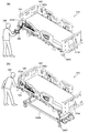
- 18A and 18B are schematic perspective views illustrating the usage state of the bed apparatus according to the embodiment.
- FIG. 19 is a schematic view illustrating the bed apparatus according to the embodiment.
- 20A and 20B are schematic views illustrating a part of the bed apparatus according to the embodiment.
- 21A and 21B are schematic views illustrating a part of the bed apparatus according to the embodiment.
- FIG. 22 is a schematic view illustrating a part of the bed apparatus according to the embodiment.
- FIG. 23 is a schematic perspective view illustrating a part of the bed apparatus according to the embodiment.
- FIG. 24 is a schematic view illustrating a part of the bed apparatus according to the embodiment.
- 25A and 25B are schematic views illustrating a part of the bed apparatus according to the embodiment.
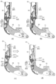
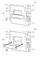
- FIGS. 1A to 1C are schematic perspective views illustrating the bed apparatus according to the first embodiment.
- 1A and 1B illustrate different states of the bed apparatus 110.
- FIG. 1C illustrates a part of the bed apparatus 110 in an enlarged manner.
- the bed apparatus 110 includes a frame 75, side rails 72, and a holding unit 50.
- the holding unit 50 holds the side rail 72.
- a plurality of side rails (side rail 72 and another side rail 72A) and a plurality of holding portions (holding portion 50 and another holding portion 50A) are provided.
- the other side rail 72A may be the same as the side rail 72 except for the size and the position where it is provided.
- Another holding part 50A holds another side rail 72A.
- the side rail 72, the holding portion 50, and the like may be provided on each of the left and right sides of the bed. Below, one side rail 72 and one holding part 50 will be described.
- the frame 75 is fixed to the base frame 75B, for example.
- a bottom (not shown) is provided on the frame 75, and a mattress 78M is provided thereon.
- a user of the bed apparatus 110 can lie on the mattress 78M.
- the bed apparatus 110 includes a headboard 78A and a footboard 78B.
- the direction from the headboard 78A to the footboard 78B corresponds to the "longitudinal direction”.
- the direction intersecting the "longitudinal direction” corresponds to the "width direction”.
- the “width direction” corresponds to, for example, the “left-right direction” when the user is sleeping on the mattress 78M.
- the frame 75 extends, for example, in the “longitudinal direction”.
- the holding unit 50 is fixed to the frame 75.
- One part of the holding part 50 is fixed to the frame 75.
- Another portion of the holding portion 50 is connected to the side rail 72.
- the holding unit 50 holds the side rail 72.
- the holding unit 50 holds the side rail 72 in a plurality of states.
- FIG. 1A illustrates the first position state SP1.
- FIG. 1B illustrates the second position state SP2.
- the first position state SP1 the side rail 72 is in the first position.
- the second position state SP2 the side rail 72 is in the second position.
- the second position is lower than the first position.
- the holding portion 50 holds the side rail 72 so as to be switchable between the first position state SP1 and the second position state SP2.
- the position of the upper end of the side rail 72 in the first position state SP1 (raised state) is higher than the position of the upper surface of the mattress 78M.
- the position of the upper end of the side rail 72 in the second position state SP2 (down state) is lower than the position of the upper surface of the mattress 78M.
- the holding part 50 includes a cover part 52, a lever part 53, and a stopper part 54.
- the holding unit 50 further includes a lock unit 51 (see FIG. 2A and the like) described later).
- the cover 52 is provided with a recess 52a. At least a part of the lever portion 53 is provided in the recess 52a of the cover portion 52.
- At least a part of the stopper 54 is in the recess 52a. Then, at least a part of the stopper portion 54 is below the lever portion 53 in the recess 52a.
- the lock part 51 locks the side rail 72 in the first position state SP1.
- the cover portion 52 covers at least a part of the lock portion 51.
- the lever portion 53 is operated to unlock the lock portion 51.
- the stopper portion 54 makes it difficult for the lever portion 53 to release the lock.
- FIG. 2A to 2D and FIG. 3 are schematic cross-sectional views illustrating the bed apparatus according to the first embodiment. These figures are sectional views corresponding to the section taken along the line A1-A2 of FIG.
- the holding part 50 includes a lock part 51, a cover part 52, a lever part 53, and a stopper part 54.
- the side rail 72 is in the first position state SP1 (raised state).
- the lock unit 51 has a lock state SLK (see FIG. 2A) and an unlock state SUL (see FIG. 2D).
- the lock portion 51 locks the side rail 72 in the first position state SP1.
- the lock portion 51 includes a hook portion 51A and a pin portion 51P.
- the pin portion 51P is fixed to the lock component 58.
- the hook portion 51A is hooked on the pin portion 51P.
- the lock portion 51 locks the side rail 72 in the first position state SP1.
- the cover part 52 covers at least a part (front part) of the lock part 51.
- the wiping property is improved and the internal mechanism can be hidden.
- lever portion 53 is provided in the recess 52a of the cover portion 52.
- the user or caregiver of the bed apparatus 110 can touch the lever portion 53.
- the lever part 53 can have a plurality of states.
- the plurality of states include, for example, a non-released state SUR (see FIG. 2A) and a released state SRS (see FIG. 2D).
- a non-released state SUR see FIG. 2A
- a released state SRS see FIG. 2D
- the lock portion 51 is in the locked state SLK.
- the lever portion 53 is in the non-released state SUR, the lock portion 51 does not shift to the unlocked state SUL.
- the side rail 72 can shift to the unlocked state SUL.
- the stopper portion 54 can also have a plurality of states.
- the plurality of states includes a first state ST1 (see FIG. 2A) and a second state ST2 (see FIG. 2B).
- first state ST1 see FIG. 2A
- second state ST2 see FIG. 2B
- the first state ST1 is a lock release difficulty state (or a lock release prohibition state).
- the second state ST2 is an unlockable state.
- the transition of the lever portion 53 to the release state SRS when the stopper portion 54 is in the first state ST1 is more than the transition of the lever portion 53 to the release state SRS when the stopper portion 54 is in the second state ST2. Have difficulty. When the stopper portion 54 is in the second state ST2, the lever portion 53 is easier to shift to the release state SRS than when the stopper portion 54 is in the first state ST1.
- the lever portion 53 is in the non-released state SUR.
- the stopper 54 is in the first state ST1.
- the stopper portion 54 is in the raised state so that the stopper portion 54 substantially contacts the lower portion of the lever portion 53. Since the stopper portion 54 is substantially in contact with the lower portion of the lever portion 53, it is possible to prevent a finger of a user or the like from accidentally entering between the stopper portion 54 and the lever portion 53. Since the stopper portion 54 is in the first state ST1, it is possible to prevent the user from operating the lever portion 53.
- the stopper 54 can be moved downward by an operation of a caregiver, for example.
- the end of the stopper portion 54 rotates around one axis, and the stopper portion 54 is in a lowered state. This state corresponds to the second state ST2 of the stopper portion 54.
- a gap is created between the lever portion 53 and the stopper portion 54.
- the width of this gap (the distance in the vertical direction) is such that the caregiver's finger can enter. By putting a hand in this gap, a caregiver or the like can touch the lower portion of the lever portion 53.
- the lever portion 53 can shift to the release state SRS (see FIG. 2D) that releases the lock state SLK of the lock portion 51.
- FIG. 2C another state (state of FIG. 2(c)) is provided between the state of FIG. 2(b) and the state of FIG. 2(d).
- the holding portion 50 or the side rail 72
- the hook portion 51A of the lock portion 51 is released. It becomes easy to come off from the pin portion 51P.
- the end of the lever portion 53 is lifted upward by an operation of a caregiver or the like.
- the front end of the lever portion 53 rotates around the rear side shaft of the lever portion 53.
- the hook portion 51A of the lock portion 51 is disengaged from the pin portion 51P.
- the lock unit 51 is in the unlocked state SUL. In this way, by operating the lever portion 53, the lever portion 53 enters the unlocked state SRS, and the locked state SLK of the lock portion 51 is unlocked.
- the stopper portion 54 has the first state ST1 in which unlocking is difficult (or prohibited) and the second state ST2 in which unlocking can be performed.
- the user of the bed apparatus 110 is prevented from accidentally unlocking.
- the stopper portion 54 after the stopper portion 54 has been moved downward (see FIG. 2B), the holding portion 50 (or the side rail 72) is pushed toward the mattress 78M (FIG. 2C). There is). In the embodiment, the stopper portion 54 may be moved downward after the holding portion 50 (or the side rail 72) is pushed toward the mattress 78M side.
- the distance between at least part of the stopper part 54 and at least part of the lever part 53 when the stopper part 54 is in the first state ST1 is such that the stopper part 54 is in the second state ST2. Is shorter than the distance between the above-mentioned at least part of the stopper portion 54 and the above-mentioned at least part of the lever portion 53.
- the distance between the stopper portion 54 and the lever portion 53 is, for example, 8 mm or less. This can prevent a finger or the like from accidentally entering the space between the stopper portion 54 and the lever portion 53 in the first state ST1. This stabilizes the first state ST1 that maintains the locked state.
- the distance between the stopper portion 54 and the lever portion 53 exceeds, for example, 8 mm.
- the second state ST2 it is easy for a finger or the like to enter the space between the stopper portion 54 and the lever portion 53, and the lever portion 53 can be easily operated.
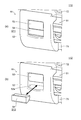
- FIG. 8A and FIG. 8B are schematic perspective views illustrating a bed apparatus according to another embodiment. These drawings exemplify the holding unit 50. The portions other than the holding portion 50 are as described with reference to FIGS. 1(a) and 1(b). In these figures, the lock portion 51 is covered with the cover portion 52 and is not visible.
- the stopper portion 54 includes a plate-shaped portion.
- a hole 54H is provided in the plate-shaped portion (stopper portion 54).
- the first portion 54Ha of the hole 54H extends in the first direction (for example, the direction of gravity).
- the second portion 54Hb of the hole 54H extends in a direction intersecting the first direction (for example, a direction along the frame 75).
- the position of the second portion 54Hb is lower than the position of the upper end of the first portion 54Ha.
- the pin 54P is inserted into the hole 54H.
- the stopper portion 54 is in the first state ST1 (lock release difficult (prohibited) state). At this time, the pin 54P is in the second portion 54Hb of the hole 54H. Thereby, the upper end of the stopper portion 54 is fixed in a state close to the lower end of the lever portion 53. The stopper portion 54 prevents the lever portion 53 from being operated.
- the stopper portion 54 is in the second state ST2 (lock release shiftable state). At this time, the pin 54P is at the upper end of the first portion 54Ha of the hole 54H. As a result, the upper end of the stopper portion 54 separates from the lower end of the lever portion 53. Thereby, the lever portion 53 can be operated.
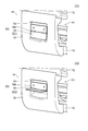
- the stopper portion 54 includes a padding member.
- the filling member can be filled in the space below the lever portion 53 in the recess 52a of the cover portion 52.
- the stopper portion 54 is in the first state ST1 (lock release difficult (prohibited) state). At this time, the filling member (stopper portion 54) is inserted in the space below the lever portion 53 in the recess 52 a of the cover portion 52. The stuffing member (stopper portion 54) makes it impossible to operate the lever portion 53.
- the stopper portion 54 is in the second state ST2 (lock release shiftable state). At this time, the filling member (stopper 54) is removed from the recess 52a of the cover 52. Thereby, the lever portion 53 can be operated.
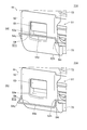
- the stopper portion 54 has a hinge shape. One side of the hinge is attached to the lever portion 53. The other side of the hinge corresponds to the stopper portion 54. One side of the hinge and the other side of the hinge are rotatably connected by the shaft portion 54x.
- the stopper portion 54 is in the first state ST1 (lock release difficult (prohibited) state). At this time, the stopper 54 closes the space under the lever 53 in the recess 52 a of the cover 52. The stopper portion 54 prevents the lever portion 53 from being operated.
- the stopper portion 54 is in the second state ST2 (lock release shiftable state). At this time, the lower portion of the lever portion 53 can be touched by rotating the stopper portion 54 upward. Thereby, the lever portion 53 can be operated.
- the stopper portion 54 includes a bar-shaped member 54p.
- the bar-shaped member 54p extends, for example, along the extending direction of the frame.
- One end of the bar-shaped member 54p is connected to the first member 54q.
- the other end of the bar-shaped member 54p is connected to the second member 54r.
- Each 8 of the 1st member 54q and the 2nd member 54r is inserted in hole 52h provided in the cover part 52, and is rotatably supported.
- the stopper portion 54 is in the first state ST1 (lock release difficult (prohibited) state).
- the bar-shaped member 54p is in front of the space below the lever portion 53. The lever portion 53 cannot be operated by the bar-shaped member 54p.
- the stopper portion 54 is in the second state ST2 (lock release shiftable state). At this time, the lower portion of the lever portion 53 can be touched by rotating the bar-shaped member 54p downward. Thereby, the lever portion 53 can be operated.
- the stopper 54 can be removed from the cover 52.
- the stopper portion 54 can be removable from the cover portion 52 by any mechanical, electrical, or magnetic method.
- the stopper 54 is attached to the cover 52 with, for example, a pin.
- the attachment may be performed by, for example, a sheet fastener or the like.
- the attachment may be performed, for example, by electrostatic force.
- the attachment may be performed using, for example, a magnet.
- the stopper portion 54 is in the first state ST1 (lock release difficult (prohibited) state). At this time, the stopper portion 54 is in front of the space below the lever portion 53. The stopper portion 54 makes it impossible to operate the lever portion 53.
- the stopper portion 54 is in the second state ST2 (lock release shiftable state). At this time, the stopper portion 54 is removed. Thereby, the lever portion 53 can be operated.
- the structure of the holding part 50 (the structure of the lock part 51, the cover part 52, the lever part 53, and the stopper part 54) can be variously modified.
- a part of the lever portion 53 is located outside the recess 52a in at least one of the non-released state SUR, the released state SRS, and the non-released state SUR and the released state SRS. It may be present (for example, see FIG. 2D).
- the stopper portion 54 since at least a part of the stopper portion 54 is in the recess 52a, it is possible to further suppress limiting the operating state of the lever portion 53.
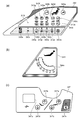
- FIG. 9 is a schematic perspective view illustrating the bed apparatus according to the embodiment.
- the bed apparatus 310 includes a right head side rail 320, a right foot side rail 330, a left head side rail 340, a left foot side rail 350, a headboard 360, and a footboard 370.
- the side rails are provided, for example, on the frame 390F of the bed 310B.
- a bottom (not shown in FIG. 9) is provided on the frame 390F of the bed 310B, and a mattress 390M is provided thereon.
- the bed 310B user can lie on the mattress 390M.
- the bed apparatus 310 is used, for example, in a hospital, a care facility, a home, or the like.
- the bed device 310 is, for example, an electric bed.
- the bed apparatus 310 can be operated by the user of the bed 310B, a caregiver, or the like.
- the angles of the head right side rail 320 and the head left side rail 340 can be changed.
- the back can be raised or the back can be lowered.
- the angle of the back bottom 70a see FIG. 17B
- the heights of the right foot side rail 330 and the left foot side rail 350 can be changed.
- the right foot side rail 330 and the left foot side rail 350 are at high positions, for example, it is possible to prevent the user from falling from the bed 310B.
- the right foot side rail 330 and the left foot side rail 350 are in the low position, for example, the user easily leaves the bed 310B from above the right foot side rail 330 and the left foot side rail 350.
- the head right side rail 320 includes an outer side surface 320F and an inner side surface 320G.
- the foot right side rail 330 includes an outer side surface 330F and an inner side surface 330G.
- the left side rail 340 includes an outer side surface 340F and an inner side surface 340G.
- the left side rail 340 includes an outer side surface 350F and an inner side surface 350G.
- switches and the like are provided on the outer side surface 320F and the inner side surface 320G of the head right side rail 320, and the outer side surface 340F and the inner side surface 340G of the head left side rail 340.
- the switches on the outer surface are designed, for example, to be conveniently operated by a caregiver or health care professional (eg, doctor, nurse or physiotherapist, etc.).
- Various switches and the like are also provided on these inner surfaces.
- the switches on the inner surface are designed, for example, to be conveniently operated by the user of bed 310B. Examples of these switches will be described later.
- Hand rails 325g, 335g, 345g, and 355g are provided on the upper portions of the right head side rail 320, the right foot side rail 330, the left head side rail 340, and the left foot side rail 350, respectively.
- the vertical width of these handrails is narrower on the inside than on the outside. Thereby, for example, a user can easily grab these handrails.
- the width of the upper surface of the hand rails 335g and 355g is designed to be wide. The user can sit on these upper surfaces (end sitting position). Thereby, for example, when the user is sitting at the end, the back of the thigh does not hurt.
- a recess is provided on the outer surface 320F of the right side rail 320 and the outer surface 340F of the left side rail 340.
- the bed operation device 380 can be attached to this recess. Further, the bed operating device 380 can be attached to the outer surface 370F of the footboard 370. The bed operation device 380 will be described later.
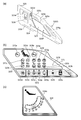
- FIG. 10A to 10C are schematic views illustrating a part of the bed apparatus according to the embodiment.
- a through hole 325h is provided in the upper portion of the head right side rail 320.
- a handrail 325g is formed by the through hole 325h.
- a convex portion 325a On the upper portion of the right side rail 320, a convex portion 325a, a concave portion 325b, a head side convex portion 325c, and a head side concave portion 325d are further provided.
- the convex portion 325a can be used, for example, as a support portion that supports the body of the user.
- the recess 325b can be used, for example, as a support portion that supports the body of the user.
- the user can easily grab the head side convex portion 325c. For example, when raising or lowering the back, it is easy to support the user's body by the head side convex portion 325c.
- a through hole is provided in the head-side convex portion 325c. Thereby, the head side convex part 325c can be used as a handrail.
- ⁇ Various medical lines can be inserted in the head side recess 325d. Easy to stabilize various lines. Various lines for medical use include cables or tubes, such as ventilators and various ME devices. By passing various lines through the head-side recess 325d, for example, it is possible to prevent these lines from being entangled.
- a switch part 323, a goniometer 324, a through hole 325e (for example, a hook part), and a lower through hole 325f (for example, a Harun bag hook) are provided on an outer surface 320F of the right side rail 320 on the head side.
- the bed operation device 380 can be suspended in the through hole 325e.
- the Harun bag can be hung in the lower through hole 325f.
- a trash can or the like can be hung in the lower through hole 325f.
- the hole 328h is provided below the through hole 325e.
- the cable of the bed operating device 380 can pass through the hole 328h.
- the cable is electrically connected to the connector provided in the bed apparatus 310 through the hole 328h. It is possible to prevent the cable from getting on the floor.
- the cable can be shortened.
- FIG. 10B illustrates the switch unit 323.
- the switch unit 323 is, for example, a membrane switch (for example, a membrane switch for medical workers).
- the switch unit 323 includes switches 323a to 323q.
- the angle between the back bottom 70a and the knee bottom 70b does not become extremely small, it is possible to prevent the user from having too much abdominal pressure while maintaining a comfortable posture. For example, if the user tilts the knee without raising it, the user may slip down. When the knee bottom 70b is raised above the horizontal angle, the user is prevented from sliding down. By “cardiac lowering", the angle between the back bottom 70a and the knee bottom 70b does not become extremely small toward the state where the back angle is 0 degrees, the knee angle is 0 degrees, and the inclination angle is 0 degrees. In this state, the bed 310B operates while keeping the knee bottom 70b raised above the horizontal angle.
- the back angle is 0 degree and the knee angle is 0 degree at first.
- the back angle becomes 5 degrees and the knee angle becomes 0 degrees.
- the back angle becomes 15 degrees and the knee angle becomes 10 degrees.
- the back angle becomes 30 degrees, the knee angle becomes 25 degrees, the back angle becomes 50 degrees, and the knee angle becomes 25 degrees.
- the back angle becomes 70 degrees and the knee angle becomes 0 degrees.
- the back angle and the knee angle increase in conjunction with each other up to the middle. Above a certain back angle, the knee angle decreases toward 0 degrees.
- the back angle is 70 degrees and the knee angle is 0 degrees at the beginning.
- the back angle becomes 50 degrees and the knee angle becomes 25 degrees.
- the back angle becomes 30 degrees and the knee angle becomes 25 degrees.
- the back angle becomes 15 degrees and the knee angle becomes 20 degrees.
- the back angle becomes 0 degree and the knee angle becomes 5 degrees. After that, the back angle becomes 0 degree and the knee angle becomes 0 degree.
- the switches 323c to 323g for “up” are located above the switches 323h to 323l for “down”.
- the user of the bed 310B may unintentionally touch the switch of the switch unit 323.
- the user of the bed 310B is more likely to touch the upper portion than the lower portion. Since the switches 323c to 323g for "raising" are on the upper side, even when the user mistakenly touches the upper portion, the risk can be further suppressed as compared with the case of touching the switches 323h to 323l.
- CPR lowering When the switch 323m is pressed, "CPR lowering" is performed.
- the bed state In the “CPR lowering”, the bed state is suitable for CPR (Cardio Pulmonary Resuscitation).
- CPR lowered In the “CPR lowered” state, the knee bottom 70b and the foot bottom 70c become flat.
- CPR lowering the floor height of the bed 310B is lowered.
- the tilt angle In the tilted state, the tilt angle is also 0 degree.
- the operation sequence is as follows. The back angle is set to 0 degree (while the back bottom 70a is being moved, the knee bottom is also brought close to 0 degree). Next, the tilt angle is set to 0 degree. Next, lower the height. Next, the knee angle is set to 0 degree.
- the bed 310B may be in the lowest floor height state.
- a position (temporary stop height) at which the bed 310B is temporarily stopped may be provided by an operation of “lowering the height”. If the height is higher than the temporary stop height in the state before the “CPR lowering”, the height of the bed 310B is temporarily set to the stop height by the “CPR lowering”. Once at stop height, the distance from the floor to the top of the bottom is about 42 cm.
- the switch 323m when the switch 323m is "long pressed", “CPR lowering” is performed.
- the “long press” time is, for example, 2 seconds or more.
- the switch 323m when the switch 323m is “pressed twice", “CPR down” is performed.
- the switch 323m is “pressed twice", the time between "pressing first” and “pressing second” is within 5 seconds.
- CPR lowering is an electric CPR operation. In addition to this, a manual CPR operation may be performed.
- the switch 323n is a “nurse call”. When the switch 323n is pressed, a nurse call is made. Information is transmitted to the nurse call system.
- the switch unit 323 includes displays 323r to 323t.
- the display 323r displays the remaining battery level.
- the display 323s is lit (for example, orange) when the floor height is not the lowest.
- the display 323s is turned off when the floor height is the lowest.
- the display 323t displays an error. At the normal time, the display 323t disappears.
- the "U system abnormality” occurs, lighting for 1 second and turning off for 1 second are repeated.
- “H system abnormality” lighting for 0.2 seconds and turning off for 0.2 seconds are repeated.
- the operation by the switch unit 323 (for example, the membrane switch for medical workers) on the outer side surface 320F is prioritized over the operation by the switch unit (for example, the user membrane switch) described below provided on the inner side surface 320G.
- the switch unit for example, the user membrane switch
- FIG. 10C illustrates the goniometer 324 provided on the outer surface 320F of the right side rail 320 on the head side.
- a recess is provided on the right side rail 320 of the head, and a sphere (for example, a metal ball) provided with the recess serves as an angle meter 324.
- a sphere for example, a metal ball
- the angle display on the display unit 324a of the angle meter 324 changes according to the position of the sphere.
- the outline of the back angle can be known.
- FIG. 11A and 11B are schematic views illustrating a part of the bed apparatus according to the embodiment.
- a recess 328 is provided on the inner side surface 320G of the right head side rail 320.
- the recess 328 can be used as a hook.
- a hole 328h is provided below the recess 328.
- the switch portion 327 is provided on the inner surface 320G.
- the switch unit 327 is, for example, a membrane switch (for example, a user membrane switch or a patient membrane switch).
- the switch unit 327 includes switches 327a to 327d.
- the switch unit 327 may include a switch 327n.
- a switch 327n is provided on the inner surface 320G.
- the switch 327n is a “nurse call”.
- a USB terminal 327u is provided on the inner surface 320G.
- a USB plug can be inserted into the USB terminal 327u for charging.
- the above-described configuration of the head right side rail 320 is also applied to the head left side rail 340.
- 12A to 12C are schematic views illustrating a part of the bed apparatus according to the embodiment.
- 12A and 12B illustrate the switch unit 343 and the goniometer 344 provided on the outer surface 340F of the left side rail 340 on the head side.
- the switch unit 343 includes switches 343a to 343q.
- the switches 343a to 343q have the same functions as the switches 323a to 323q.
- the switch unit 343 includes displays 343r to 343t.
- the displays 343r to 343t have the same functions as the displays 323r to 323t.
- FIG. 12B illustrates the goniometer 344.
- the goniometer 344 has the same structure and function as the goniometer 324.
- the display section 344a of the goniometer 344 can provide an overview of the back angle.
- a switch unit 347 is provided on the inner side surface 340G (see FIG. 9) of the left side rail 340 of the head.
- the switch unit 347 has the same structure and function as the switch unit 327.
- the switch unit 347 includes switches 347a to 347d.
- the switches 347a to 347d have the same functions as the switches 327a to 327d.
- the switch 347n and the USB terminal 347u are provided on the inner surface 320G.
- the USB terminal 347u may be omitted.
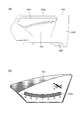
- FIG. 13A and 13B are schematic views illustrating a part of the bed apparatus according to the embodiment.
- a hand rail 335g is provided on the right side rail 330 of the foot.
- the handrail 335g is formed by the through hole 335h.
- a lower through hole 335f (for example, Harun bag hook) is provided in the lower portion of the right side rail 330 of the foot.
- a Harun bag or the like can be hung in the lower through hole 335f.
- An angle meter 334 is provided on the outer surface 330F of the right side rail 330 of the foot (see FIG. 13B).
- the goniometer 334 has a structure similar to that of the goniometer 324.
- the display unit 334a of the goniometer 334 can provide an overview of the angle.
- FIG. 14 is a schematic view illustrating a part of the bed apparatus according to the embodiment. As shown in FIG. 14, the handrail 335g is obtained by the through hole 335h formed in the right side rail 330 of the foot.
- FIG. 15 is a schematic diagram which illustrates a part of bed apparatus which concerns on embodiment.
- FIG. 15 illustrates the goniometer 354 provided on the outer surface 350F of the left side rail 350.
- the goniometer 354 has a structure similar to that of the goniometer 324.
- the display unit 354a of the goniometer 354 can provide an overview of the angle.
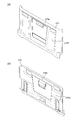
- FIG. 16A and 16B are schematic views illustrating a part of the bed apparatus according to the embodiment.
- a through hole 375e (for example, a hook portion) is provided on the outer surface 370F of the footboard 370.
- the bed operation device 380 can be suspended in the through hole 375e.
- the through hole 375e penetrates the inner side surface 370G of the footboard 370.
- the bed operation device 380 can display various settings regarding the bed 310B and the weight of the user.
- a “home button” is provided as a “physical button” in the bed operation device 380.
- An example of the bed operating device 380 will be described later.
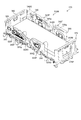
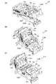
- 17(a) to 17(c) are schematic perspective views illustrating the operation of the bed apparatus according to the embodiment. These figures exemplify the state when the mattress 390M is not provided.
- the frame 390F is attached to the base frame 390B.
- a back bottom 70a back section
- a knee bottom 70b upper leg section
- a foot bottom 70c lower leg section
- the like are provided on the frame 390F.
- a waist bottom 70e is provided.
- the casters 390C may be provided on the base frame 390B.
- the angle (tilt) of the frame 390F can be changed.
- the tilt may include a left-right tilt as well as a front-back tilt.
- the respective angles of the back bottom 70a, the knee bottom 70b, and the foot bottom 70c can be changed.
- the angles of the head right side rail 320 and the head left side rail 340 change according to the change of the angle of the back bottom 70a.
- the head right side rail 320 and the head left side rail 340 are follow-up side rails.
- the state of FIG. 17B corresponds to the Cardiac position.
- the foot right side rail 330 and the foot left side rail 350 are in the “upper state”.
- the foot right side rail 330 and the foot left side rail 350 can be in the “down state”.
- the height of the bed 310B can be changed.
- the height corresponds to the distance between the upper surface of the bed 310B (for example, the upper surface of the bottom) and the floor surface, for example.
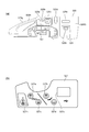
- FIG. 18A and 18B are schematic perspective views illustrating the usage state of the bed apparatus according to the embodiment.
- FIG. 18A illustrates a state where the bed 310B is low.
- a caregiver or the like 398 (for example, a caregiver or a medical worker) can operate the bed operation device 380 with the bed operation device 380 removed from the hook portion (for example, the through hole 325e of the right side head rail 320).
- FIG. 18B illustrates a state in which the bed 310B is high.
- a caregiver 399 or the like can operate the bed operation device 380 while the bed operation device 380 is attached to the hook portion.
- the bed operation device 380 is attached to, for example, three hook portions.
- the three hook portions are a through hole 325e of the head right side rail 320, a through hole 345e of the head left side rail 340, and a through hole 375e of the foot board 370.
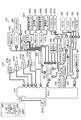
- FIG. 19 is a schematic view illustrating the bed apparatus according to the embodiment.
- a control box 410 is provided in the bed apparatus 310.
- various devices are provided in the bed device 310.
- Various devices include a junction box 420, a membrane switch 430, a leglight 440, a side rail sensor 450 (SR sensor), a caster lock sensor 455 (CL sensor), a nurse call 457a, a nurse call 457b, a nurse call relay unit 458, a scale.
- the unit 460, the load cell 465, the actuator 470, the battery 475, etc. are included. Some of the various devices may be omitted.
- the control box 410 can be connected to various devices. The connection between the control box 410 and various devices is made directly or via the junction box 420.
- the control box 410 controls the bed operation and various functions.
- the control box 410 serves as a master for serial communication in the bed apparatus 310.
- the control box 410 is provided with a plug 410P (for example, a 3-pin plug). Electric power is supplied to the control box 410 from the plug 410P. Electric power is supplied from the control box 410 to various devices.
- a plug 410P for example, a 3-pin plug. Electric power is supplied to the control box 410 from the plug 410P. Electric power is supplied from the control box 410 to various devices.
- the junction box 420 relays the connection between the control box 410 and various other devices.
- the membrane switch 430 includes membrane switches 430a and 430b for medical personnel. These membrane switches correspond to the switch units 323 and 343. Membrane switch 430 includes patient membrane switches 430c and 430d. These membrane switches correspond to the switch units 327 and 347.
- the medical worker membrane switch 430a and the patient membrane switch 430c are connected to the junction box 420 via the relay unit 431a.
- the membrane switch 430b for medical workers and the membrane switch 430d for patients are connected to the junction box 420 via the relay unit 431b.
- Bed operation buttons are provided on the membrane switches 430a and 430b for medical staff.
- the bed operation buttons are cardiac operation buttons (for example, interlocking operation buttons), extension/reverse extension buttons, kind motion operation buttons (for example, other interlocking operation buttons), CPR buttons, nurse calls. Includes buttons, patient membrane switch inhibit buttons, and all switch inhibit buttons. The operation described with respect to the switch units 323 and 343 is performed by these bed operation buttons.
- Bed operation buttons are provided on the patient membrane switches 430c and 430d.
- the bed operation buttons include the back bottom operation button, the knee bottom operation button, and the nurse call button.
- the patient membrane switches 430c and 430d may include charging terminals and the like.
- the bed operation button is provided at an intermediate position in the vertical direction. If the bed operation button is at the bottom, it is difficult to operate. If the bed operation button is at the top, it may be operated accidentally. Since the bed operation button is located at an intermediate position in the up-down direction, the operation becomes easy, and erroneous operation can be suppressed.
- the footlight button corresponds to the switches 323q and 343q.
- the footlight 440 illuminates.
- the foot lamp 440 illuminates the floor surface from the end of the bed 310B.
- the leg lights 440 are provided, for example, one on each side of the bed 310B.
- the leg lights 440 are provided, for example, at the left and right ends on the back side (lower side) of the waist bottom 70e.
- the leg lights 440 may be provided in other parts such as the back bottom 70a, the knee bottom 70b, and the foot bottom 70c (see FIG. 17B and the like).
- the leglight 440 is repeatedly turned off, dimly turned on, brightly turned on, and turned off.
- the leg light 440 is turned on by a medical staff. For example, when the user frequently goes to the toilet, the medical staff turns on the leglight 440 before the user goes to bed. For example, when a bed leaving is detected, or when a nurse call occurs, the medical staff turns on the leglight 440.
- the leg light 440 is turned on. At this time, the room is often dark. When the leglights 440 suddenly turn on brightly, people sleeping in the vicinity are annoyed. By turning on the light at first, annoyance is suppressed.
- the side rail sensor 450 detects whether or not each side rail is raised.
- Four siderail sensors 450 are provided.
- the four side rail sensors 450 include a head right side rail sensor, a head left side rail sensor, a foot right side rail sensor, and a foot left side rail sensor.
- the detection result is displayed on the terminal of the nurse station, for example.
- the detection result may be displayed on the bed operation device 380.
- a warning sound may be generated based on the detection result.
- As the side rail sensor 450 for example, a magnetic sensor or an atmospheric pressure sensor is used. Other sensors may be used as the side rail sensor 450.
- the caster lock sensor 455 detects whether or not the caster 390C is locked.
- a magnetic sensor is used as the caster lock sensor 455, for example.
- the caster 390C is provided with a bar or the like interlocking with the lock or unlock of the caster 390C.
- the locked state of the caster 390C can be detected by detecting the state of the bar.
- the detection result of the caster lock sensor 455 is displayed on the terminal of the nurse station, for example.
- the detection result may be displayed on the bed operation device 380.
- a warning sound may be generated based on the detection result of the caster lock sensor 455.
- the nurse call 457a is connected to the junction box 420.
- the nurse call 457b is connected to the nurse call relay unit 458.
- the nurse call relay unit 458 enables cooperation with a nurse call (for example, nurse call 457b) provided in hospitals and facilities.
- Nurse calls 457a and 457b are domestic or foreign nurse calls.
- the nurse call 457a is made in a foreign country.
- the nurse call 457b is made in Japan.
- the load cells 465 are provided at the four corners of the bed 310B. Four load cells 465 are used.
- the load cell 465 and the scale unit 460 can measure the weight of the user.
- the actuator 470 includes a height changing actuator 470a (“HLACT”), a knee bottom 70b actuator 470b (“knee ACT”), a back bottom 70a actuator 470c (CPR-equipped “back ACT”), and The height changing actuator 470d (“HLACT”) and the like are included.
- the actuators 470a and 470d include load sensors.
- the actuator 470c for the back bottom 70a includes a mechanical mechanism (hereinafter, referred to as a manual CPR mechanism) for performing a lowering operation manually.
- the manual CPR mechanism allows the back bottom 70a to be manually lowered in an emergency.
- a dedicated lever or the like is provided, and by operating this lever, the back bottom 70a can be manually lowered to obtain a posture for CPR.
- the brake plate of the actuator 470c for the back bottom 70a can be manually displaced. As a result, the brake of the actuator 470c is released, and the back bottom 70a is lowered by its own weight.
- the actuator 470 serves as a drive source for adjusting the movable part included in the bed 310B.
- the actuator 470 operates the movable portion via the link mechanism or the like by the operation of the telescopic rod.
- a position sensor is provided for each of the actuators. The position information is read by the control box 410.
- the load sensor of the actuator 470 may determine the movement of the user (patient, etc.) on the bed 310B (including, for example, leaving the bed).
- the battery 475 supplies electric power during a power failure or during transportation of the bed 310B.
- the desired operation can be obtained even in the situation where there is no power supply.
- a switch for charging/not charging the battery 475 may be provided. Charging may be possible as long as power (AC power) is supplied to the bed 310B regardless of the state of the changeover switch.
- the bed apparatus 310 when the bed apparatus 310 is driven by an AC power source, power is supplied from the control box 410 to the battery 475, the air mattress control unit 482 and the USB charger 488 (see FIG. 19).
- power is supplied from the battery 475 to the control box 410, the air mattress control unit 482, and the USB charger 488.
- the bed 310B When power is not supplied from the AC power supply and power is not supplied from the battery 475, the bed 310B does not operate.
- a sleep sensor 481, an air mattress control unit 482, and a bed operation apparatus 380 are provided in the bed apparatus 310.
- a hand switch 483 may be provided in the bed apparatus 310.
- the sleep sensor 481 measures the sleep status of the user (patient, etc.) of the bed 310B.
- the sleep status measurement result and the sleep history may be output (for example, displayed) to the bed operation device 380.
- control box 410 is provided with a connector for the air mattress control unit 482.
- the interlocking operation may be performed according to the posture of the bed 310B.
- the interlocking operation may differ depending on the type of air mattress.
- the bed operation device 380 may set and change the operation of the air mattress.
- the bed device 310 is further provided with an auxiliary outlet 485.
- two auxiliary outlets 485 are provided.
- the auxiliary outlet 485 is a plug receiving device.
- the auxiliary outlet 485 includes a plug 485P.
- the plug 485P is a plug that meets medical standards.
- the plug 485P is a 3-pin plug.
- the plug 485P is provided separately from the plug 410P of the control box 410.
- the bed apparatus 310 may include a USB charger 488 (see FIG. 19).
- the USB charger 488 corresponds to the USB terminal 327u (or 347u).
- the USB charger 488 supplies power to a device compatible with USB charging.
- the number of ports of the USB charger 488 may be one.
- the output rating of the USB charger 488 is DC 5V/1A.
- the port is provided on the patient membrane switch 430c on the right siderail.
- the bed device 310 may include an error display LED.
- the error display LED corresponds to the displays 323t and 343t.
- the bed device 310 may detect that the user of the bed 310B has left the bed. For example, leaving the bed is detected by the load cell 465. For example, the leaving sensor is detected by a load sensor incorporated in the actuator. Information about leaving the bed is transmitted to the nurse call system and output to the terminal of the nurse station. The information regarding leaving the bed may be output to the bed operation device 380. The output of information regarding leaving the bed may include, for example, a visual stimulus such as a lamp or an auditory stimulus such as a warning sound.
- the bed operation device 380 is connected to the bed 310B.
- the bed operation device 380 can set and display the settings related to the bed 310B. It is possible to switch the display language on the bed operation device 380. For example, it is possible to display in Japanese, English, Chinese or Portuguese.
- the bed operation device 380 is attached to, for example, the left and right side rails or the footboard 370.
- the maximum number of bed operation devices 380 provided in the bed device 310 is 3, for example.
- one bed operation device 380 or one hand switch 483 (described later) is connected to the bed 310B.
- one bed operation device 380 and one hand switch 483 are connected to the bed 310B.
- two bed operating devices 380 are connected to the bed 310B.
- two bed operation devices 380 and one hand switch 483 are connected to the bed 310B.
- three bed operation devices 380 are connected to the bed 310B.
- FIG. 20A and 20B are schematic views illustrating a part of the bed apparatus according to the embodiment.
- FIG. 20A illustrates the bed operating device 380 mainly provided on the head side rail (the head right side rail 320 or the head left side rail 340).
- the bed operation device 380 includes a display input unit 380D.
- the bed operation device 380 is provided with a home button 380h.
- various displays can be made on the display input unit 380D.
- the display input unit 380D can display the posture of the bed 310B and the weight of the user.
- the display input unit 380D allows setting of the bed leaving sensor.
- a display regarding the sleep sensor 481 can be performed by the display input unit 380D.
- the display input unit 380D allows the operation of the air mattress. An error can be displayed by the display input unit 380D.
- FIG. 21A and 21B are schematic views illustrating a part of the bed apparatus according to the embodiment.
- FIG. 21A illustrates the bed operation device 380 mainly provided on the footboard 370.
- the bed operation device 380 includes a display input unit 380D.
- the bed operation device 380 is provided with an up button 380a, a down button 380b, and a CPR button 380c.
- the up button 380a or the down button 380b moves up or down the movable part of the bed 310B.
- the CPR button 380c the posture is changed to CPR.
- various displays can be made on the display input unit 380D.
- the display input unit 380D can operate the bed 310B.
- the bed operation includes, for example, cardiac operation, tilting operation, interlocking operation (kind operation), raising and lowering the back, raising and lowering the knee, and raising and lowering the height.
- the display input unit 380D can display the weight of the user.
- the display input unit 380D allows setting of the bed leaving sensor.
- a display regarding the sleep sensor 481 can be performed by the display input unit 380D.
- the display input unit 380D allows the operation of the air mattress. An error can be displayed by the display input unit 380D.
- FIG. 22 is a schematic view illustrating a part of the bed apparatus according to the embodiment.
- FIG. 22 illustrates the hand switch 483.
- the hand switch 483 includes switch pairs 483a to 483d.
- Switch pair 483a includes a switch for raising or lowering for "interlocking" operation.
- Switch pair 483b includes a switch for raising or lowering for "back raising” movement.
- Switch pair 483c includes a switch for raising or lowering for a "foot lift” action.
- the switch pair 483d includes a switch for raising or lowering regarding the “height” changing operation.
- the angle or height may be displayed on the display portion 483D of the hand switch 483.
- the hand switch 483 is connected to, for example, the control box 410 by a cable 483e or the like.
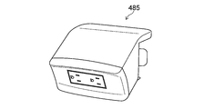
- FIG. 23 is a schematic perspective view illustrating a part of the bed apparatus according to the embodiment.
- FIG. 23 illustrates an auxiliary outlet 485 (for example, a plug receiving device). Plugs of electronic devices used around the bed 310B can be connected to the auxiliary outlet 485.
- the plug 485P of the auxiliary outlet 485 is provided separately from the plug 410P of the control box 410.
- the auxiliary outlet 485 has two sets of plug receivers (plug insertion holes). The two sets of plug receivers are arranged side by side.
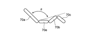
- FIG. 24 is a schematic view illustrating a part of the bed apparatus according to the embodiment.
- FIG. 24 illustrates the back bottom 70a, the knee bottom 70b, the foot bottom 70c, and the waist bottom 70e.
- the angles of the back bottom 70a, the knee bottom 70b, and the foot bottom 70c can be changed. It is controlled so that the angle between the bottoms does not fall below a predetermined value (for example, 90 degrees).
- a predetermined value for example, 90 degrees
- the angle between the line connecting the lower end of the back bottom 70a and the upper end of the knee bottom 70b (broken line in FIG. 24) and the back bottom 70a is controlled to be a predetermined value (for example, 90 degrees) or less.
- the angle is made equal to or less than a predetermined value.
- the operation angle of the back bottom 70a is, for example, 0 degrees to 70 degrees.
- the operation angle of the knee bottom 70b is 0 degrees or more and 25 degrees or less.
- the operating range of "height" is, for example, 43 cm.
- the floor height may vary depending on the bed frame. The floor height range is, for example, 30 cm to 73 cm, 32.5 cm to 75.5 cm, or 35 cm to 78 cm.
- the operating angle of the bottom tilt is -15 to 15 degrees.
- the tilting operation is performed after the height is adjusted to the height of “minimum floor height+3 cm”.
- the operations are performed in the following order. At that time, if the simultaneous operation is possible, the simultaneous operation may be performed.
- the stroke of the actuator 470c (“back ACT”) for the back bottom 70a is operated to the lower limit.
- the lower limit of the actuator 470c is reached within 30 seconds after the button for the electric CPR operation is pressed.
- the tilting operation is performed and the tilt angle becomes 0 degree.
- height adjustment is performed and the height becomes the minimum floor height.
- the minimum floor height is, for example, “temporary stop height”.
- the knee bottom 70b is moved to 0 degree.
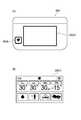
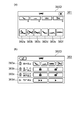
- FIG. 25A and 25B are schematic views illustrating a part of the bed apparatus according to the embodiment. These drawings exemplify the display input unit 380D of the bed operation device 380.
- FIG. 25A illustrates a case where the display input unit 380D is the bed operation screen 381.
- FIG. 25B illustrates a case where the display input unit 380D is the actuator individual operation prohibition screen 383 (bed setting screen).
- buttons 382a to 382f are provided. These buttons are, for example, input acceptance areas in the touch input device. By touching these buttons, bed operation is performed.
- the cardiac operation is performed by the button 382a.
- the tilt operation is performed by the button 382b.
- a linked operation (“kind operation”) is performed by the button 382c.
- the back movement is performed by the button 382d.
- a knee operation (change of knee angle) is performed by the button 382e.
- a height operation (change of height) is performed by the button 382f. For example, when raising the height of the bed 310B, pressing the button 382d and then pressing the lift button 380a moves the bed 310B.
- the bed 310B moves while pressing the up button 380a. For example, when lowering the height of the bed, if the button 382f is pressed and then the lowering button 380b is pressed, the height of the bed 310B is lowered while the lowering button 380b is being pressed.
- the display input unit 380D can be moved to the actuator individual operation prohibition screen 383 (bed setting screen).
- the actuator individual operation prohibition screen 383 bed setting screen.
- the back motion, knee motion, height motion, and tilt motion can be individually prohibited.
- the display input area 383b By operating the display input area 383b, all operations can be prohibited or the operation prohibition can be released.
- the display input area 383c By operating the display input area 383c, the operation of the hand switch 483 can be prohibited or the operation prohibition can be released.
- back movements are prohibited, cardiac movements, interlocking movements and back movements are prohibited.
- the Cardiac movement, the interlocking movement, and the knee movement are prohibited.
- the height motion is prohibited, the Cardiac motion, the tilt motion, and the height motion are prohibited.
- the tilting motion is prohibited, the Cardiac motion and the tilting motion are prohibited.
- the actuator 470 (such as 470a to 470d (see FIG. 19)) may be selectively (individually) “inhibited”. The release of the “operation prohibited” of the actuator 470 is released by the bed operation device 380.
- the prohibition of the operation of the actuator 470, the prohibition of the operation of the hand switch 483, or the prohibition of all the operations are managed independently. For example, when the individual operation of the actuator 470 is prohibited, the “all operation prohibited” is set, and thereafter, even if the “all operation prohibited” is released, the individual operation prohibition of the actuator 470 remains.
- a buzzer sounds and the prohibit LED (eg, display 323t and 343t) of the membrane switch blinks. If you don't hear a buzzer, you don't know if the button is banned or broken. A buzzer sounds to indicate that the button is prohibited.
- the hand switch 483 When the prohibited button on the hand switch 483 is pressed, the hand switch 483 sounds. When a prohibited button on the membrane switch is pressed, for example, the junction box 420 sounds.
- the membrane switch for medical staff or the bed operation device 380 By operating the membrane switch for medical staff or the bed operation device 380, the operation of the membrane switch for patients and the hand switch 483 can be disabled. The operation prohibition can be released if the medical worker membrane switch or the bed operation device 380 is connected.
- All operations can be prohibited by operating the membrane switch for medical staff or the bed operating device 380 (“All operations prohibited”). This operation prohibition can be released if either the membrane switch for medical staff or the bed navigation is connected.
- the bed operation device 380 is not connected to the bed 310B, or if there is a partial failure (communication failure), the “all operations prohibited” is released. In this case, for example, it can be operated by the hand switch 483. If the user does not want to operate it, the hand switch 483 may be removed. When the prohibited button is pressed, a buzzer sounds and the prohibit LED of the membrane switch blinks.
- the operation speed can be changed by operating the display input area 383d illustrated in FIG. 25(b).
- the speed of various operations can be changed in multiple stages (eg, two stages).
- History of various operations of the bed apparatus 310 may be stored.
- the history is stored in a memory such as the control box 410.
- the memory for storing the history may be provided in the junction box 420, the hand switch 483, or the like.
- the memory in which the history is stored may be provided in the bed operation device 380.
- Information about history is not reset by powering on/off.
- the history information includes, for example, the operation history of the control box 410, the operation history of the actuator 470, the operation history of the hand switch 483, the operation content history, the failure history, and the separated floor history.
Landscapes
- Health & Medical Sciences (AREA)
- Life Sciences & Earth Sciences (AREA)
- Nursing (AREA)
- Animal Behavior & Ethology (AREA)
- General Health & Medical Sciences (AREA)
- Public Health (AREA)
- Veterinary Medicine (AREA)
- Engineering & Computer Science (AREA)
- Molecular Biology (AREA)
- Pathology (AREA)
- Physics & Mathematics (AREA)
- Biomedical Technology (AREA)
- Heart & Thoracic Surgery (AREA)
- Medical Informatics (AREA)
- Biophysics (AREA)
- Surgery (AREA)
- Rehabilitation Therapy (AREA)
- Physiology (AREA)
- Dentistry (AREA)
- Oral & Maxillofacial Surgery (AREA)
- Invalid Beds And Related Equipment (AREA)
Abstract
Selon un mode de réalisation, cet appareil de lit comprend un cadre, des rails latéraux et des parties de maintien. Les parties de maintien sont fixées au cadre. Les parties de maintien maintiennent respectivement les rails latéraux de façon à être commutables entre un premier état de position, dans lequel les rails latéraux sont dans une première position, et un second état de position dans lequel les rails latéraux sont dans une seconde position plus basse que la première position. Chaque partie de maintien comprend : une partie de verrouillage qui verrouille le rail latéral correspondant dans le premier état de position ; une partie de couvercle qui recouvre au moins partiellement la partie de verrouillage ; une partie de levier qui est actionnée afin de libérer le verrouillage de la partie de verrouillage ; et une partie de butée qui augmente la difficulté de l'opération par laquelle la partie de levier libère le verrouillage. Il est ainsi possible de fournir un appareil de lit qui peut réduire au minimum le risque de libérer le verrouillage par erreur.
Priority Applications (2)
| Application Number | Priority Date | Filing Date | Title |
|---|---|---|---|
| CN201980047561.8A CN113453586A (zh) | 2019-02-27 | 2019-07-30 | 床装置 |
| US17/259,435 US20210275374A1 (en) | 2019-02-27 | 2019-07-30 | Bed apparatus |
Applications Claiming Priority (2)
| Application Number | Priority Date | Filing Date | Title |
|---|---|---|---|
| JP2019035002A JP7185561B2 (ja) | 2019-02-27 | 2019-02-27 | ベッド装置 |
| JP2019-035002 | 2019-02-27 |
Publications (1)
| Publication Number | Publication Date |
|---|---|
| WO2020174717A1 true WO2020174717A1 (fr) | 2020-09-03 |
Family
ID=72239276
Family Applications (1)
| Application Number | Title | Priority Date | Filing Date |
|---|---|---|---|
| PCT/JP2019/029760 WO2020174717A1 (fr) | 2019-02-27 | 2019-07-30 | Appareil de lit |
Country Status (4)
| Country | Link |
|---|---|
| US (1) | US20210275374A1 (fr) |
| JP (2) | JP7185561B2 (fr) |
| CN (1) | CN113453586A (fr) |
| WO (1) | WO2020174717A1 (fr) |
Families Citing this family (2)
| Publication number | Priority date | Publication date | Assignee | Title |
|---|---|---|---|---|
| JP7185561B2 (ja) * | 2019-02-27 | 2022-12-07 | パラマウントベッド株式会社 | ベッド装置 |
| WO2023202480A1 (fr) * | 2022-04-22 | 2023-10-26 | 毕威泰克(浙江)医疗器械有限公司 | Système de détection d'état de lit d'hôpital, et structure de lit d'hôpital |
Citations (6)
| Publication number | Priority date | Publication date | Assignee | Title |
|---|---|---|---|---|
| JPH0586750A (ja) * | 1991-09-13 | 1993-04-06 | Sony Corp | 開閉扉の施錠装置 |
| JP2002136554A (ja) * | 2000-11-02 | 2002-05-14 | Paramount Bed Co Ltd | ベッド等における格納型側柵の折畳み構造 |
| JP2003135220A (ja) * | 2001-10-31 | 2003-05-13 | Paramount Bed Co Ltd | 不測のロック解除防止機能を有するベッドにおける側柵装置 |
| JP2008029799A (ja) * | 2006-07-03 | 2008-02-14 | Paramount Bed Co Ltd | ベッド等の仰臥台における側柵のステーロック機構 |
| JP2015123177A (ja) * | 2013-12-26 | 2015-07-06 | パラマウントベッド株式会社 | ベッドサイド構造 |
| CN208435969U (zh) * | 2017-12-11 | 2019-01-29 | 河北普康医疗设备有限公司 | 一种防误操作的医疗床用护栏解锁装置 |
Family Cites Families (42)
| Publication number | Priority date | Publication date | Assignee | Title |
|---|---|---|---|---|
| US4653129A (en) * | 1986-04-25 | 1987-03-31 | Midmark Corporation | Side rail assembly for a wheeled stretcher |
| US5083334A (en) * | 1990-10-12 | 1992-01-28 | Ssi Medical Services, Inc. | Side guard for patient support |
| US5732423A (en) * | 1995-08-04 | 1998-03-31 | Hill-Rom, Inc. | Bed side rails |
| JP2970806B1 (ja) * | 1998-07-28 | 1999-11-02 | パラマウントベッド株式会社 | ベッド等における格納型側柵 |
| JP2927417B1 (ja) * | 1998-08-05 | 1999-07-28 | パラマウントベッド株式会社 | ベッド等における格納型側柵 |
| DE19900602C1 (de) * | 1999-01-11 | 2000-07-13 | Wissner Bosserhoff Gmbh | Seitengitter für ein Kranken- oder Pflegebett |
| US6446283B1 (en) * | 1999-01-22 | 2002-09-10 | Hill-Rom Services, Inc. | Convertible stretcher |
| US6519794B1 (en) * | 1999-09-25 | 2003-02-18 | Sunrise Medical Hhg Inc. | Side rail, side rail kinematic, and lock lever and lock pin for side rail |
| US7073220B2 (en) * | 2002-09-06 | 2006-07-11 | Hill-Rom Services, Inc. | Bed siderail having a latch |
| BRPI0508629A (pt) * | 2004-03-12 | 2007-08-07 | Hill Rom Services Inc | trilho lateral para uso com um suporte para paciente |
| CA2487543A1 (fr) * | 2004-11-10 | 2006-05-10 | Hill-Rom Services, Inc. | Amortisseur a ressort pour cote de lit |
| JP5137116B2 (ja) * | 2007-01-15 | 2013-02-06 | パラマウントベッド株式会社 | 折り畳み式サイドレールにおける保持機構 |
| JP5001795B2 (ja) * | 2007-11-13 | 2012-08-15 | パラマウントベッド株式会社 | 病院搬送用ストレッチャー等の柵及びそのロック機構 |
| US8104118B2 (en) * | 2008-01-21 | 2012-01-31 | Stryker Corporation | Hospital bed |
| US8239986B2 (en) * | 2008-03-13 | 2012-08-14 | Hill-Rom Services, Inc. | Siderail assembly for a patient-support apparatus |
| JP5365357B2 (ja) * | 2009-06-12 | 2013-12-11 | トヨタ紡織株式会社 | 車両用シートの操作レバー装置 |
| US8646131B2 (en) * | 2010-07-30 | 2014-02-11 | Hill-Rom Services, Inc. | Variable height siderail |
| EP3210586B1 (fr) * | 2010-07-09 | 2019-08-28 | Hill-Rom Services, Inc. | Dispositif de fixation pour un réservoir de fluide sur des systèmes de support de patient |
| US20120011652A1 (en) * | 2010-07-14 | 2012-01-19 | Jacobs Neal K | Siderail assembly |
| US8713727B2 (en) * | 2010-07-30 | 2014-05-06 | Hill-Rom Services, Inc. | Siderail assembly for patient support apparatus |
| US9629768B2 (en) * | 2010-07-30 | 2017-04-25 | Hill-Rom Services, Inc. | Variable height siderail |
| US9101517B2 (en) * | 2010-08-30 | 2015-08-11 | Hill-Rom Services, Inc. | Patient-support apparatus with a configurable siderail |
| WO2012066580A2 (fr) * | 2010-11-19 | 2012-05-24 | Sundaram Medical Devices (P) Ltd | Lit d'hôpital |
| US20120144583A1 (en) * | 2010-12-08 | 2012-06-14 | Turner Jonathan D | Siderail movable to separate chair egress position |
| US8621688B2 (en) * | 2010-12-13 | 2014-01-07 | Hill-Rom Services, Inc. | Siderail assembly for patient support apparatus |
| KR101268188B1 (ko) * | 2011-05-18 | 2013-05-27 | 박순덕 | 침대의 절첩식 사이드레일 |
| US20130086746A1 (en) * | 2011-10-10 | 2013-04-11 | Irvin J. Vanderpohl | Patient support apparatus with movable siderail assembly |
| US9050228B2 (en) * | 2012-03-13 | 2015-06-09 | Hill-Rom S.A.S. | Siderail latching mechanism |
| ITTV20120074A1 (it) * | 2012-05-08 | 2013-11-09 | Favero Health Projects Spa | "sponda di protezione abbattibile e rimovibile per letto ospedaliero con dispositivo di vincolo a scorrimento dotato di dispositivo di aggancio/sgancio di sicurezza" |
| CZ2012363A3 (cs) * | 2012-05-31 | 2014-05-07 | Linet Spol. S. R. O. | Postranice lůžka |
| KR20140120599A (ko) * | 2013-04-04 | 2014-10-14 | 주식회사 퍼시스 | 침대용 사이드레일 |
| DE102014109988B4 (de) * | 2014-07-16 | 2017-08-24 | Joh. Stiegelmeyer Gmbh & Co. Kg | Kranken- und/oder Pflegebett und ein Seitengitter |
| US10058468B2 (en) * | 2014-08-28 | 2018-08-28 | Umano Medical Inc. | Siderail system for a bed |
| DE102014115552B4 (de) * | 2014-10-27 | 2018-01-18 | Joh. Stiegelmeyer Gmbh & Co Kg | Seitengitter für ein Kranken- und/oder Pflegebett |
| JP6419031B2 (ja) * | 2015-06-30 | 2018-11-07 | パラマウントベッド株式会社 | ベッド用サイドレール |
| WO2018074936A1 (fr) * | 2016-10-19 | 2018-04-26 | Howard Wright Limited | Rail latéral |
| CN107134381A (zh) * | 2017-05-17 | 2017-09-05 | 郑州云海信息技术有限公司 | 一种存储设备及其防误触开关 |
| EP3403637A1 (fr) * | 2017-05-19 | 2018-11-21 | Simps'S d.o.o. | Lit d'hôpital |
| JP7040925B2 (ja) * | 2017-11-29 | 2022-03-23 | パラマウントベッド株式会社 | 管理サーバ及びプログラム |
| JP7185561B2 (ja) * | 2019-02-27 | 2022-12-07 | パラマウントベッド株式会社 | ベッド装置 |
| JP7125361B2 (ja) * | 2019-02-27 | 2022-08-24 | パラマウントベッド株式会社 | 構造体 |
| JP7017837B2 (ja) * | 2019-04-15 | 2022-02-09 | 株式会社大一商会 | 遊技機 |
-
2019
- 2019-02-27 JP JP2019035002A patent/JP7185561B2/ja active Active
- 2019-07-30 US US17/259,435 patent/US20210275374A1/en active Pending
- 2019-07-30 WO PCT/JP2019/029760 patent/WO2020174717A1/fr active Application Filing
- 2019-07-30 CN CN201980047561.8A patent/CN113453586A/zh active Pending
-
2022
- 2022-11-25 JP JP2022187936A patent/JP7430236B2/ja active Active
Patent Citations (6)
| Publication number | Priority date | Publication date | Assignee | Title |
|---|---|---|---|---|
| JPH0586750A (ja) * | 1991-09-13 | 1993-04-06 | Sony Corp | 開閉扉の施錠装置 |
| JP2002136554A (ja) * | 2000-11-02 | 2002-05-14 | Paramount Bed Co Ltd | ベッド等における格納型側柵の折畳み構造 |
| JP2003135220A (ja) * | 2001-10-31 | 2003-05-13 | Paramount Bed Co Ltd | 不測のロック解除防止機能を有するベッドにおける側柵装置 |
| JP2008029799A (ja) * | 2006-07-03 | 2008-02-14 | Paramount Bed Co Ltd | ベッド等の仰臥台における側柵のステーロック機構 |
| JP2015123177A (ja) * | 2013-12-26 | 2015-07-06 | パラマウントベッド株式会社 | ベッドサイド構造 |
| CN208435969U (zh) * | 2017-12-11 | 2019-01-29 | 河北普康医疗设备有限公司 | 一种防误操作的医疗床用护栏解锁装置 |
Also Published As
| Publication number | Publication date |
|---|---|
| JP7185561B2 (ja) | 2022-12-07 |
| JP2020137724A (ja) | 2020-09-03 |
| US20210275374A1 (en) | 2021-09-09 |
| JP7430236B2 (ja) | 2024-02-09 |
| CN113453586A (zh) | 2021-09-28 |
| JP2023010991A (ja) | 2023-01-20 |
Similar Documents
| Publication | Publication Date | Title |
|---|---|---|
| JP7430236B2 (ja) | ベッド装置 | |
| WO2020217557A1 (fr) | Dispositif de commande et dispositif de lit | |
| JP6453376B2 (ja) | 電話ドックおよびベッド頭部のロックアウト付き患者コントロールアーム | |
| JP6549624B2 (ja) | 患者ベッド制御のための介護者汎用遠隔カート | |
| US9414980B2 (en) | Bed, and combining method and separating method of bed | |
| JP6968085B2 (ja) | 表示器デバイス | |
| US20130219615A1 (en) | Patient Stand Assist and Therapy Devices and Methods | |
| US11723821B2 (en) | Patient support apparatus for controlling patient ingress and egress | |
| EP2436354A2 (fr) | Ensemble de support du haut du corps | |
| WO2020174716A1 (fr) | Structure | |
| CN113573681B (zh) | 护理装置 | |
| JP7458529B2 (ja) | ベッド操作受け付け装置及びベッド装置 | |
| WO2018184507A1 (fr) | Lit médicalisé | |
| CN107951631A (zh) | 方便上下床的残疾人轮椅 | |
| JP7190369B2 (ja) | ベッド装置 | |
| JP7227034B2 (ja) | プラグ受け装置及びベッド装置 | |
| JPS601022B2 (ja) | 看護ロボツト | |
| JP6685790B2 (ja) | 寝台装置 | |
| JP6719937B2 (ja) | 寝台装置 | |
| JP7045413B2 (ja) | 寝台装置 | |
| JP3244998U (ja) | 一体型自動寝返りベッドシステム | |
| JP7125456B2 (ja) | 電動家具 | |
| CN215535835U (zh) | 一种智能护理床 | |
| JP2022069681A (ja) | 寝台装置 | |
| JP2023086853A (ja) | 寝台装置 |
Legal Events
| Date | Code | Title | Description |
|---|---|---|---|
| 121 | Ep: the epo has been informed by wipo that ep was designated in this application |
Ref document number: 19917328 Country of ref document: EP Kind code of ref document: A1 |
|
| NENP | Non-entry into the national phase |
Ref country code: DE |
|
| 122 | Ep: pct application non-entry in european phase |
Ref document number: 19917328 Country of ref document: EP Kind code of ref document: A1 |