WO2020174717A1 - Bed apparatus - Google Patents
Bed apparatus Download PDFInfo
- Publication number
- WO2020174717A1 WO2020174717A1 PCT/JP2019/029760 JP2019029760W WO2020174717A1 WO 2020174717 A1 WO2020174717 A1 WO 2020174717A1 JP 2019029760 W JP2019029760 W JP 2019029760W WO 2020174717 A1 WO2020174717 A1 WO 2020174717A1
- Authority
- WO
- WIPO (PCT)
- Prior art keywords
- bed
- state
- switch
- side rail
- lock
- Prior art date
Links
Images


Classifications
-
- A—HUMAN NECESSITIES
- A61—MEDICAL OR VETERINARY SCIENCE; HYGIENE
- A61G—TRANSPORT, PERSONAL CONVEYANCES, OR ACCOMMODATION SPECIALLY ADAPTED FOR PATIENTS OR DISABLED PERSONS; OPERATING TABLES OR CHAIRS; CHAIRS FOR DENTISTRY; FUNERAL DEVICES
- A61G7/00—Beds specially adapted for nursing; Devices for lifting patients or disabled persons
- A61G7/05—Parts, details or accessories of beds
- A61G7/0507—Side-rails
- A61G7/0508—Side-rails characterised by a particular connection mechanism
- A61G7/0509—Side-rails characterised by a particular connection mechanism sliding or pivoting downwards
-
- A—HUMAN NECESSITIES
- A61—MEDICAL OR VETERINARY SCIENCE; HYGIENE
- A61G—TRANSPORT, PERSONAL CONVEYANCES, OR ACCOMMODATION SPECIALLY ADAPTED FOR PATIENTS OR DISABLED PERSONS; OPERATING TABLES OR CHAIRS; CHAIRS FOR DENTISTRY; FUNERAL DEVICES
- A61G7/00—Beds specially adapted for nursing; Devices for lifting patients or disabled persons
- A61G7/05—Parts, details or accessories of beds
- A61G7/0507—Side-rails
- A61G7/0508—Side-rails characterised by a particular connection mechanism
-
- A—HUMAN NECESSITIES
- A47—FURNITURE; DOMESTIC ARTICLES OR APPLIANCES; COFFEE MILLS; SPICE MILLS; SUCTION CLEANERS IN GENERAL
- A47C—CHAIRS; SOFAS; BEDS
- A47C21/00—Attachments for beds, e.g. sheet holders, bed-cover holders; Ventilating, cooling or heating means in connection with bedsteads or mattresses
- A47C21/08—Devices for prevention against falling-out, e.g. detachable sidewalls
-
- A—HUMAN NECESSITIES
- A61—MEDICAL OR VETERINARY SCIENCE; HYGIENE
- A61B—DIAGNOSIS; SURGERY; IDENTIFICATION
- A61B5/00—Measuring for diagnostic purposes; Identification of persons
- A61B5/103—Detecting, measuring or recording devices for testing the shape, pattern, colour, size or movement of the body or parts thereof, for diagnostic purposes
- A61B5/11—Measuring movement of the entire body or parts thereof, e.g. head or hand tremor, mobility of a limb
- A61B5/1113—Local tracking of patients, e.g. in a hospital or private home
- A61B5/1115—Monitoring leaving of a patient support, e.g. a bed or a wheelchair
-
- A—HUMAN NECESSITIES
- A61—MEDICAL OR VETERINARY SCIENCE; HYGIENE
- A61B—DIAGNOSIS; SURGERY; IDENTIFICATION
- A61B5/00—Measuring for diagnostic purposes; Identification of persons
- A61B5/68—Arrangements of detecting, measuring or recording means, e.g. sensors, in relation to patient
- A61B5/6887—Arrangements of detecting, measuring or recording means, e.g. sensors, in relation to patient mounted on external non-worn devices, e.g. non-medical devices
- A61B5/6891—Furniture
-
- A—HUMAN NECESSITIES
- A61—MEDICAL OR VETERINARY SCIENCE; HYGIENE
- A61B—DIAGNOSIS; SURGERY; IDENTIFICATION
- A61B5/00—Measuring for diagnostic purposes; Identification of persons
- A61B5/68—Arrangements of detecting, measuring or recording means, e.g. sensors, in relation to patient
- A61B5/6887—Arrangements of detecting, measuring or recording means, e.g. sensors, in relation to patient mounted on external non-worn devices, e.g. non-medical devices
- A61B5/6892—Mats
-
- A—HUMAN NECESSITIES
- A61—MEDICAL OR VETERINARY SCIENCE; HYGIENE
- A61G—TRANSPORT, PERSONAL CONVEYANCES, OR ACCOMMODATION SPECIALLY ADAPTED FOR PATIENTS OR DISABLED PERSONS; OPERATING TABLES OR CHAIRS; CHAIRS FOR DENTISTRY; FUNERAL DEVICES
- A61G7/00—Beds specially adapted for nursing; Devices for lifting patients or disabled persons
- A61G7/002—Beds specially adapted for nursing; Devices for lifting patients or disabled persons having adjustable mattress frame
- A61G7/005—Beds specially adapted for nursing; Devices for lifting patients or disabled persons having adjustable mattress frame tiltable around transverse horizontal axis, e.g. for Trendelenburg position
-
- A—HUMAN NECESSITIES
- A61—MEDICAL OR VETERINARY SCIENCE; HYGIENE
- A61G—TRANSPORT, PERSONAL CONVEYANCES, OR ACCOMMODATION SPECIALLY ADAPTED FOR PATIENTS OR DISABLED PERSONS; OPERATING TABLES OR CHAIRS; CHAIRS FOR DENTISTRY; FUNERAL DEVICES
- A61G7/00—Beds specially adapted for nursing; Devices for lifting patients or disabled persons
- A61G7/002—Beds specially adapted for nursing; Devices for lifting patients or disabled persons having adjustable mattress frame
- A61G7/012—Beds specially adapted for nursing; Devices for lifting patients or disabled persons having adjustable mattress frame raising or lowering of the whole mattress frame
-
- A—HUMAN NECESSITIES
- A61—MEDICAL OR VETERINARY SCIENCE; HYGIENE
- A61G—TRANSPORT, PERSONAL CONVEYANCES, OR ACCOMMODATION SPECIALLY ADAPTED FOR PATIENTS OR DISABLED PERSONS; OPERATING TABLES OR CHAIRS; CHAIRS FOR DENTISTRY; FUNERAL DEVICES
- A61G7/00—Beds specially adapted for nursing; Devices for lifting patients or disabled persons
- A61G7/002—Beds specially adapted for nursing; Devices for lifting patients or disabled persons having adjustable mattress frame
- A61G7/015—Beds specially adapted for nursing; Devices for lifting patients or disabled persons having adjustable mattress frame divided into different adjustable sections, e.g. for Gatch position
-
- A—HUMAN NECESSITIES
- A61—MEDICAL OR VETERINARY SCIENCE; HYGIENE
- A61G—TRANSPORT, PERSONAL CONVEYANCES, OR ACCOMMODATION SPECIALLY ADAPTED FOR PATIENTS OR DISABLED PERSONS; OPERATING TABLES OR CHAIRS; CHAIRS FOR DENTISTRY; FUNERAL DEVICES
- A61G7/00—Beds specially adapted for nursing; Devices for lifting patients or disabled persons
- A61G7/05—Parts, details or accessories of beds
- A61G7/0503—Holders, support devices for receptacles, e.g. for drainage or urine bags
-
- A—HUMAN NECESSITIES
- A61—MEDICAL OR VETERINARY SCIENCE; HYGIENE
- A61G—TRANSPORT, PERSONAL CONVEYANCES, OR ACCOMMODATION SPECIALLY ADAPTED FOR PATIENTS OR DISABLED PERSONS; OPERATING TABLES OR CHAIRS; CHAIRS FOR DENTISTRY; FUNERAL DEVICES
- A61G7/00—Beds specially adapted for nursing; Devices for lifting patients or disabled persons
- A61G7/05—Parts, details or accessories of beds
- A61G7/0507—Side-rails
- A61G7/0512—Side-rails characterised by customised length
- A61G7/0513—Side-rails characterised by customised length covering particular sections of the bed, e.g. one or more partial side-rail sections along the bed
-
- A—HUMAN NECESSITIES
- A61—MEDICAL OR VETERINARY SCIENCE; HYGIENE
- A61G—TRANSPORT, PERSONAL CONVEYANCES, OR ACCOMMODATION SPECIALLY ADAPTED FOR PATIENTS OR DISABLED PERSONS; OPERATING TABLES OR CHAIRS; CHAIRS FOR DENTISTRY; FUNERAL DEVICES
- A61G7/00—Beds specially adapted for nursing; Devices for lifting patients or disabled persons
- A61G7/05—Parts, details or accessories of beds
- A61G7/0507—Side-rails
- A61G7/052—Side-rails characterised by safety means, e.g. to avoid injuries to patient or caregiver
- A61G7/0521—Anti-pinching means to avoid injuries to body parts when moving side-rails or mattress supports, e.g. gap and grid covers, side-rail parts with special shape or electronic means for warning
-
- A—HUMAN NECESSITIES
- A61—MEDICAL OR VETERINARY SCIENCE; HYGIENE
- A61G—TRANSPORT, PERSONAL CONVEYANCES, OR ACCOMMODATION SPECIALLY ADAPTED FOR PATIENTS OR DISABLED PERSONS; OPERATING TABLES OR CHAIRS; CHAIRS FOR DENTISTRY; FUNERAL DEVICES
- A61G7/00—Beds specially adapted for nursing; Devices for lifting patients or disabled persons
- A61G7/05—Parts, details or accessories of beds
- A61G7/0507—Side-rails
- A61G7/0524—Side-rails characterised by integrated accessories, e.g. bed control means, nurse call or reading lights
-
- A—HUMAN NECESSITIES
- A61—MEDICAL OR VETERINARY SCIENCE; HYGIENE
- A61G—TRANSPORT, PERSONAL CONVEYANCES, OR ACCOMMODATION SPECIALLY ADAPTED FOR PATIENTS OR DISABLED PERSONS; OPERATING TABLES OR CHAIRS; CHAIRS FOR DENTISTRY; FUNERAL DEVICES
- A61G7/00—Beds specially adapted for nursing; Devices for lifting patients or disabled persons
- A61G7/05—Parts, details or accessories of beds
- A61G7/0527—Weighing devices
-
- A—HUMAN NECESSITIES
- A61—MEDICAL OR VETERINARY SCIENCE; HYGIENE
- A61B—DIAGNOSIS; SURGERY; IDENTIFICATION
- A61B2562/00—Details of sensors; Constructional details of sensor housings or probes; Accessories for sensors
- A61B2562/02—Details of sensors specially adapted for in-vivo measurements
- A61B2562/0252—Load cells
-
- A—HUMAN NECESSITIES
- A61—MEDICAL OR VETERINARY SCIENCE; HYGIENE
- A61G—TRANSPORT, PERSONAL CONVEYANCES, OR ACCOMMODATION SPECIALLY ADAPTED FOR PATIENTS OR DISABLED PERSONS; OPERATING TABLES OR CHAIRS; CHAIRS FOR DENTISTRY; FUNERAL DEVICES
- A61G2203/00—General characteristics of devices
- A61G2203/10—General characteristics of devices characterised by specific control means, e.g. for adjustment or steering
- A61G2203/12—Remote controls
-
- A—HUMAN NECESSITIES
- A61—MEDICAL OR VETERINARY SCIENCE; HYGIENE
- A61G—TRANSPORT, PERSONAL CONVEYANCES, OR ACCOMMODATION SPECIALLY ADAPTED FOR PATIENTS OR DISABLED PERSONS; OPERATING TABLES OR CHAIRS; CHAIRS FOR DENTISTRY; FUNERAL DEVICES
- A61G2203/00—General characteristics of devices
- A61G2203/30—General characteristics of devices characterised by sensor means
-
- A—HUMAN NECESSITIES
- A61—MEDICAL OR VETERINARY SCIENCE; HYGIENE
- A61G—TRANSPORT, PERSONAL CONVEYANCES, OR ACCOMMODATION SPECIALLY ADAPTED FOR PATIENTS OR DISABLED PERSONS; OPERATING TABLES OR CHAIRS; CHAIRS FOR DENTISTRY; FUNERAL DEVICES
- A61G7/00—Beds specially adapted for nursing; Devices for lifting patients or disabled persons
- A61G7/05—Parts, details or accessories of beds
- A61G7/0506—Head or foot boards
Definitions
- the embodiment of the present invention relates to a bed apparatus.
- a bed has side rails that can move vertically.
- the side rail When the side rail is on the upper side, the user can be prevented from falling from the bed.
- the side rail On the other hand, when the side rail is below, the user can be encouraged to leave the bed. It becomes safer by locking the vertical movement of the side rail. It is desirable to prevent accidental unlocking.
- the embodiment of the present invention provides a bed apparatus that can prevent accidental unlocking.
- the bed apparatus includes a frame, side rails, and a holding unit.
- the holding part is fixed to the frame.
- the holding portion is switchable between a first position state in which the side rail is in a first position and a second position state in which the side rail is in a second position lower than the first position.
- the holding portion includes a lock portion that locks the side rail in the first position state, a cover portion that covers at least a part of the lock portion, and a lever portion that is operated to unlock the lock portion. And a stopper portion that makes it difficult to release the lock by the lever portion.
- FIG. 1A to 1C are schematic perspective views illustrating the bed apparatus according to the first embodiment.
- 2A to 2D are schematic cross-sectional views illustrating the bed apparatus according to the first embodiment.
- FIG. 3 is a schematic cross-sectional view illustrating the bed apparatus according to the first embodiment.
- FIG. 4A and FIG. 4B are schematic perspective views illustrating a bed apparatus according to another embodiment.
- FIG. 5A and FIG. 5B are schematic perspective views illustrating a bed apparatus according to another embodiment.
- FIG. 6A and FIG. 6B are schematic perspective views illustrating a bed apparatus according to another embodiment.
- FIG. 7A and FIG. 7B are schematic perspective views illustrating a bed apparatus according to another embodiment.
- FIG. 8A and FIG. 8B are schematic perspective views illustrating a bed apparatus according to another embodiment.
- FIG. 9 is a schematic perspective view illustrating the bed apparatus according to the embodiment.
- 10A to 10C are schematic views illustrating a part of the bed apparatus according to the embodiment.
- 11A and 11B are schematic views illustrating a part of the bed apparatus according to the embodiment.
- 12A to 12C are schematic views illustrating a part of the bed apparatus according to the embodiment.
- 13A and 13B are schematic views illustrating a part of the bed apparatus according to the embodiment.
- FIG. 14 is a schematic view illustrating a part of the bed apparatus according to the embodiment.
- FIG. 15 is a schematic diagram which illustrates a part of bed apparatus which concerns on embodiment.
- 16A and 16B are schematic views illustrating a part of the bed apparatus according to the embodiment.
- FIG. 17(a) to 17(c) are schematic perspective views illustrating the operation of the bed apparatus according to the embodiment.
- 18A and 18B are schematic perspective views illustrating the usage state of the bed apparatus according to the embodiment.
- FIG. 19 is a schematic view illustrating the bed apparatus according to the embodiment.
- 20A and 20B are schematic views illustrating a part of the bed apparatus according to the embodiment.
- 21A and 21B are schematic views illustrating a part of the bed apparatus according to the embodiment.
- FIG. 22 is a schematic view illustrating a part of the bed apparatus according to the embodiment.
- FIG. 23 is a schematic perspective view illustrating a part of the bed apparatus according to the embodiment.
- FIG. 24 is a schematic view illustrating a part of the bed apparatus according to the embodiment.
- 25A and 25B are schematic views illustrating a part of the bed apparatus according to the embodiment.
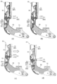
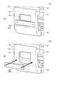
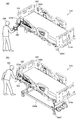
- FIGS. 1A to 1C are schematic perspective views illustrating the bed apparatus according to the first embodiment.
- 1A and 1B illustrate different states of the bed apparatus 110.
- FIG. 1C illustrates a part of the bed apparatus 110 in an enlarged manner.
- the bed apparatus 110 includes a frame 75, side rails 72, and a holding unit 50.
- the holding unit 50 holds the side rail 72.
- a plurality of side rails (side rail 72 and another side rail 72A) and a plurality of holding portions (holding portion 50 and another holding portion 50A) are provided.
- the other side rail 72A may be the same as the side rail 72 except for the size and the position where it is provided.
- Another holding part 50A holds another side rail 72A.
- the side rail 72, the holding portion 50, and the like may be provided on each of the left and right sides of the bed. Below, one side rail 72 and one holding part 50 will be described.
- the frame 75 is fixed to the base frame 75B, for example.
- a bottom (not shown) is provided on the frame 75, and a mattress 78M is provided thereon.
- a user of the bed apparatus 110 can lie on the mattress 78M.
- the bed apparatus 110 includes a headboard 78A and a footboard 78B.
- the direction from the headboard 78A to the footboard 78B corresponds to the "longitudinal direction”.
- the direction intersecting the "longitudinal direction” corresponds to the "width direction”.
- the “width direction” corresponds to, for example, the “left-right direction” when the user is sleeping on the mattress 78M.
- the frame 75 extends, for example, in the “longitudinal direction”.
- the holding unit 50 is fixed to the frame 75.
- One part of the holding part 50 is fixed to the frame 75.
- Another portion of the holding portion 50 is connected to the side rail 72.
- the holding unit 50 holds the side rail 72.
- the holding unit 50 holds the side rail 72 in a plurality of states.
- FIG. 1A illustrates the first position state SP1.
- FIG. 1B illustrates the second position state SP2.
- the first position state SP1 the side rail 72 is in the first position.
- the second position state SP2 the side rail 72 is in the second position.
- the second position is lower than the first position.
- the holding portion 50 holds the side rail 72 so as to be switchable between the first position state SP1 and the second position state SP2.
- the position of the upper end of the side rail 72 in the first position state SP1 (raised state) is higher than the position of the upper surface of the mattress 78M.
- the position of the upper end of the side rail 72 in the second position state SP2 (down state) is lower than the position of the upper surface of the mattress 78M.
- the holding part 50 includes a cover part 52, a lever part 53, and a stopper part 54.
- the holding unit 50 further includes a lock unit 51 (see FIG. 2A and the like) described later).
- the cover 52 is provided with a recess 52a. At least a part of the lever portion 53 is provided in the recess 52a of the cover portion 52.
- At least a part of the stopper 54 is in the recess 52a. Then, at least a part of the stopper portion 54 is below the lever portion 53 in the recess 52a.
- the lock part 51 locks the side rail 72 in the first position state SP1.
- the cover portion 52 covers at least a part of the lock portion 51.
- the lever portion 53 is operated to unlock the lock portion 51.
- the stopper portion 54 makes it difficult for the lever portion 53 to release the lock.
- FIG. 2A to 2D and FIG. 3 are schematic cross-sectional views illustrating the bed apparatus according to the first embodiment. These figures are sectional views corresponding to the section taken along the line A1-A2 of FIG.
- the holding part 50 includes a lock part 51, a cover part 52, a lever part 53, and a stopper part 54.
- the side rail 72 is in the first position state SP1 (raised state).
- the lock unit 51 has a lock state SLK (see FIG. 2A) and an unlock state SUL (see FIG. 2D).
- the lock portion 51 locks the side rail 72 in the first position state SP1.
- the lock portion 51 includes a hook portion 51A and a pin portion 51P.
- the pin portion 51P is fixed to the lock component 58.
- the hook portion 51A is hooked on the pin portion 51P.
- the lock portion 51 locks the side rail 72 in the first position state SP1.
- the cover part 52 covers at least a part (front part) of the lock part 51.
- the wiping property is improved and the internal mechanism can be hidden.
- lever portion 53 is provided in the recess 52a of the cover portion 52.
- the user or caregiver of the bed apparatus 110 can touch the lever portion 53.
- the lever part 53 can have a plurality of states.
- the plurality of states include, for example, a non-released state SUR (see FIG. 2A) and a released state SRS (see FIG. 2D).
- a non-released state SUR see FIG. 2A
- a released state SRS see FIG. 2D
- the lock portion 51 is in the locked state SLK.
- the lever portion 53 is in the non-released state SUR, the lock portion 51 does not shift to the unlocked state SUL.
- the side rail 72 can shift to the unlocked state SUL.
- the stopper portion 54 can also have a plurality of states.
- the plurality of states includes a first state ST1 (see FIG. 2A) and a second state ST2 (see FIG. 2B).
- first state ST1 see FIG. 2A
- second state ST2 see FIG. 2B
- the first state ST1 is a lock release difficulty state (or a lock release prohibition state).
- the second state ST2 is an unlockable state.
- the transition of the lever portion 53 to the release state SRS when the stopper portion 54 is in the first state ST1 is more than the transition of the lever portion 53 to the release state SRS when the stopper portion 54 is in the second state ST2. Have difficulty. When the stopper portion 54 is in the second state ST2, the lever portion 53 is easier to shift to the release state SRS than when the stopper portion 54 is in the first state ST1.
- the lever portion 53 is in the non-released state SUR.
- the stopper 54 is in the first state ST1.
- the stopper portion 54 is in the raised state so that the stopper portion 54 substantially contacts the lower portion of the lever portion 53. Since the stopper portion 54 is substantially in contact with the lower portion of the lever portion 53, it is possible to prevent a finger of a user or the like from accidentally entering between the stopper portion 54 and the lever portion 53. Since the stopper portion 54 is in the first state ST1, it is possible to prevent the user from operating the lever portion 53.
- the stopper 54 can be moved downward by an operation of a caregiver, for example.
- the end of the stopper portion 54 rotates around one axis, and the stopper portion 54 is in a lowered state. This state corresponds to the second state ST2 of the stopper portion 54.
- a gap is created between the lever portion 53 and the stopper portion 54.
- the width of this gap (the distance in the vertical direction) is such that the caregiver's finger can enter. By putting a hand in this gap, a caregiver or the like can touch the lower portion of the lever portion 53.
- the lever portion 53 can shift to the release state SRS (see FIG. 2D) that releases the lock state SLK of the lock portion 51.
- FIG. 2C another state (state of FIG. 2(c)) is provided between the state of FIG. 2(b) and the state of FIG. 2(d).
- the holding portion 50 or the side rail 72
- the hook portion 51A of the lock portion 51 is released. It becomes easy to come off from the pin portion 51P.
- the end of the lever portion 53 is lifted upward by an operation of a caregiver or the like.
- the front end of the lever portion 53 rotates around the rear side shaft of the lever portion 53.
- the hook portion 51A of the lock portion 51 is disengaged from the pin portion 51P.
- the lock unit 51 is in the unlocked state SUL. In this way, by operating the lever portion 53, the lever portion 53 enters the unlocked state SRS, and the locked state SLK of the lock portion 51 is unlocked.
- the stopper portion 54 has the first state ST1 in which unlocking is difficult (or prohibited) and the second state ST2 in which unlocking can be performed.
- the user of the bed apparatus 110 is prevented from accidentally unlocking.
- the stopper portion 54 after the stopper portion 54 has been moved downward (see FIG. 2B), the holding portion 50 (or the side rail 72) is pushed toward the mattress 78M (FIG. 2C). There is). In the embodiment, the stopper portion 54 may be moved downward after the holding portion 50 (or the side rail 72) is pushed toward the mattress 78M side.
- the distance between at least part of the stopper part 54 and at least part of the lever part 53 when the stopper part 54 is in the first state ST1 is such that the stopper part 54 is in the second state ST2. Is shorter than the distance between the above-mentioned at least part of the stopper portion 54 and the above-mentioned at least part of the lever portion 53.
- the distance between the stopper portion 54 and the lever portion 53 is, for example, 8 mm or less. This can prevent a finger or the like from accidentally entering the space between the stopper portion 54 and the lever portion 53 in the first state ST1. This stabilizes the first state ST1 that maintains the locked state.
- the distance between the stopper portion 54 and the lever portion 53 exceeds, for example, 8 mm.
- the second state ST2 it is easy for a finger or the like to enter the space between the stopper portion 54 and the lever portion 53, and the lever portion 53 can be easily operated.
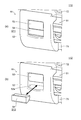
- FIG. 8A and FIG. 8B are schematic perspective views illustrating a bed apparatus according to another embodiment. These drawings exemplify the holding unit 50. The portions other than the holding portion 50 are as described with reference to FIGS. 1(a) and 1(b). In these figures, the lock portion 51 is covered with the cover portion 52 and is not visible.
- the stopper portion 54 includes a plate-shaped portion.
- a hole 54H is provided in the plate-shaped portion (stopper portion 54).
- the first portion 54Ha of the hole 54H extends in the first direction (for example, the direction of gravity).
- the second portion 54Hb of the hole 54H extends in a direction intersecting the first direction (for example, a direction along the frame 75).
- the position of the second portion 54Hb is lower than the position of the upper end of the first portion 54Ha.
- the pin 54P is inserted into the hole 54H.
- the stopper portion 54 is in the first state ST1 (lock release difficult (prohibited) state). At this time, the pin 54P is in the second portion 54Hb of the hole 54H. Thereby, the upper end of the stopper portion 54 is fixed in a state close to the lower end of the lever portion 53. The stopper portion 54 prevents the lever portion 53 from being operated.
- the stopper portion 54 is in the second state ST2 (lock release shiftable state). At this time, the pin 54P is at the upper end of the first portion 54Ha of the hole 54H. As a result, the upper end of the stopper portion 54 separates from the lower end of the lever portion 53. Thereby, the lever portion 53 can be operated.
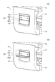
- the stopper portion 54 includes a padding member.
- the filling member can be filled in the space below the lever portion 53 in the recess 52a of the cover portion 52.
- the stopper portion 54 is in the first state ST1 (lock release difficult (prohibited) state). At this time, the filling member (stopper portion 54) is inserted in the space below the lever portion 53 in the recess 52 a of the cover portion 52. The stuffing member (stopper portion 54) makes it impossible to operate the lever portion 53.
- the stopper portion 54 is in the second state ST2 (lock release shiftable state). At this time, the filling member (stopper 54) is removed from the recess 52a of the cover 52. Thereby, the lever portion 53 can be operated.
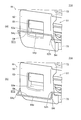
- the stopper portion 54 has a hinge shape. One side of the hinge is attached to the lever portion 53. The other side of the hinge corresponds to the stopper portion 54. One side of the hinge and the other side of the hinge are rotatably connected by the shaft portion 54x.
- the stopper portion 54 is in the first state ST1 (lock release difficult (prohibited) state). At this time, the stopper 54 closes the space under the lever 53 in the recess 52 a of the cover 52. The stopper portion 54 prevents the lever portion 53 from being operated.
- the stopper portion 54 is in the second state ST2 (lock release shiftable state). At this time, the lower portion of the lever portion 53 can be touched by rotating the stopper portion 54 upward. Thereby, the lever portion 53 can be operated.
- the stopper portion 54 includes a bar-shaped member 54p.
- the bar-shaped member 54p extends, for example, along the extending direction of the frame.
- One end of the bar-shaped member 54p is connected to the first member 54q.
- the other end of the bar-shaped member 54p is connected to the second member 54r.
- Each 8 of the 1st member 54q and the 2nd member 54r is inserted in hole 52h provided in the cover part 52, and is rotatably supported.
- the stopper portion 54 is in the first state ST1 (lock release difficult (prohibited) state).
- the bar-shaped member 54p is in front of the space below the lever portion 53. The lever portion 53 cannot be operated by the bar-shaped member 54p.
- the stopper portion 54 is in the second state ST2 (lock release shiftable state). At this time, the lower portion of the lever portion 53 can be touched by rotating the bar-shaped member 54p downward. Thereby, the lever portion 53 can be operated.
- the stopper 54 can be removed from the cover 52.
- the stopper portion 54 can be removable from the cover portion 52 by any mechanical, electrical, or magnetic method.
- the stopper 54 is attached to the cover 52 with, for example, a pin.
- the attachment may be performed by, for example, a sheet fastener or the like.
- the attachment may be performed, for example, by electrostatic force.
- the attachment may be performed using, for example, a magnet.
- the stopper portion 54 is in the first state ST1 (lock release difficult (prohibited) state). At this time, the stopper portion 54 is in front of the space below the lever portion 53. The stopper portion 54 makes it impossible to operate the lever portion 53.
- the stopper portion 54 is in the second state ST2 (lock release shiftable state). At this time, the stopper portion 54 is removed. Thereby, the lever portion 53 can be operated.
- the structure of the holding part 50 (the structure of the lock part 51, the cover part 52, the lever part 53, and the stopper part 54) can be variously modified.
- a part of the lever portion 53 is located outside the recess 52a in at least one of the non-released state SUR, the released state SRS, and the non-released state SUR and the released state SRS. It may be present (for example, see FIG. 2D).
- the stopper portion 54 since at least a part of the stopper portion 54 is in the recess 52a, it is possible to further suppress limiting the operating state of the lever portion 53.
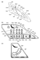
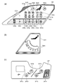
- FIG. 9 is a schematic perspective view illustrating the bed apparatus according to the embodiment.
- the bed apparatus 310 includes a right head side rail 320, a right foot side rail 330, a left head side rail 340, a left foot side rail 350, a headboard 360, and a footboard 370.
- the side rails are provided, for example, on the frame 390F of the bed 310B.
- a bottom (not shown in FIG. 9) is provided on the frame 390F of the bed 310B, and a mattress 390M is provided thereon.
- the bed 310B user can lie on the mattress 390M.
- the bed apparatus 310 is used, for example, in a hospital, a care facility, a home, or the like.
- the bed device 310 is, for example, an electric bed.
- the bed apparatus 310 can be operated by the user of the bed 310B, a caregiver, or the like.
- the angles of the head right side rail 320 and the head left side rail 340 can be changed.
- the back can be raised or the back can be lowered.
- the angle of the back bottom 70a see FIG. 17B
- the heights of the right foot side rail 330 and the left foot side rail 350 can be changed.
- the right foot side rail 330 and the left foot side rail 350 are at high positions, for example, it is possible to prevent the user from falling from the bed 310B.
- the right foot side rail 330 and the left foot side rail 350 are in the low position, for example, the user easily leaves the bed 310B from above the right foot side rail 330 and the left foot side rail 350.
- the head right side rail 320 includes an outer side surface 320F and an inner side surface 320G.
- the foot right side rail 330 includes an outer side surface 330F and an inner side surface 330G.
- the left side rail 340 includes an outer side surface 340F and an inner side surface 340G.
- the left side rail 340 includes an outer side surface 350F and an inner side surface 350G.
- switches and the like are provided on the outer side surface 320F and the inner side surface 320G of the head right side rail 320, and the outer side surface 340F and the inner side surface 340G of the head left side rail 340.
- the switches on the outer surface are designed, for example, to be conveniently operated by a caregiver or health care professional (eg, doctor, nurse or physiotherapist, etc.).
- Various switches and the like are also provided on these inner surfaces.
- the switches on the inner surface are designed, for example, to be conveniently operated by the user of bed 310B. Examples of these switches will be described later.
- Hand rails 325g, 335g, 345g, and 355g are provided on the upper portions of the right head side rail 320, the right foot side rail 330, the left head side rail 340, and the left foot side rail 350, respectively.
- the vertical width of these handrails is narrower on the inside than on the outside. Thereby, for example, a user can easily grab these handrails.
- the width of the upper surface of the hand rails 335g and 355g is designed to be wide. The user can sit on these upper surfaces (end sitting position). Thereby, for example, when the user is sitting at the end, the back of the thigh does not hurt.
- a recess is provided on the outer surface 320F of the right side rail 320 and the outer surface 340F of the left side rail 340.
- the bed operation device 380 can be attached to this recess. Further, the bed operating device 380 can be attached to the outer surface 370F of the footboard 370. The bed operation device 380 will be described later.
- FIG. 10A to 10C are schematic views illustrating a part of the bed apparatus according to the embodiment.
- a through hole 325h is provided in the upper portion of the head right side rail 320.
- a handrail 325g is formed by the through hole 325h.
- a convex portion 325a On the upper portion of the right side rail 320, a convex portion 325a, a concave portion 325b, a head side convex portion 325c, and a head side concave portion 325d are further provided.
- the convex portion 325a can be used, for example, as a support portion that supports the body of the user.
- the recess 325b can be used, for example, as a support portion that supports the body of the user.
- the user can easily grab the head side convex portion 325c. For example, when raising or lowering the back, it is easy to support the user's body by the head side convex portion 325c.
- a through hole is provided in the head-side convex portion 325c. Thereby, the head side convex part 325c can be used as a handrail.
- ⁇ Various medical lines can be inserted in the head side recess 325d. Easy to stabilize various lines. Various lines for medical use include cables or tubes, such as ventilators and various ME devices. By passing various lines through the head-side recess 325d, for example, it is possible to prevent these lines from being entangled.
- a switch part 323, a goniometer 324, a through hole 325e (for example, a hook part), and a lower through hole 325f (for example, a Harun bag hook) are provided on an outer surface 320F of the right side rail 320 on the head side.
- the bed operation device 380 can be suspended in the through hole 325e.
- the Harun bag can be hung in the lower through hole 325f.
- a trash can or the like can be hung in the lower through hole 325f.
- the hole 328h is provided below the through hole 325e.
- the cable of the bed operating device 380 can pass through the hole 328h.
- the cable is electrically connected to the connector provided in the bed apparatus 310 through the hole 328h. It is possible to prevent the cable from getting on the floor.
- the cable can be shortened.
- FIG. 10B illustrates the switch unit 323.
- the switch unit 323 is, for example, a membrane switch (for example, a membrane switch for medical workers).
- the switch unit 323 includes switches 323a to 323q.
- the angle between the back bottom 70a and the knee bottom 70b does not become extremely small, it is possible to prevent the user from having too much abdominal pressure while maintaining a comfortable posture. For example, if the user tilts the knee without raising it, the user may slip down. When the knee bottom 70b is raised above the horizontal angle, the user is prevented from sliding down. By “cardiac lowering", the angle between the back bottom 70a and the knee bottom 70b does not become extremely small toward the state where the back angle is 0 degrees, the knee angle is 0 degrees, and the inclination angle is 0 degrees. In this state, the bed 310B operates while keeping the knee bottom 70b raised above the horizontal angle.
- the back angle is 0 degree and the knee angle is 0 degree at first.
- the back angle becomes 5 degrees and the knee angle becomes 0 degrees.
- the back angle becomes 15 degrees and the knee angle becomes 10 degrees.
- the back angle becomes 30 degrees, the knee angle becomes 25 degrees, the back angle becomes 50 degrees, and the knee angle becomes 25 degrees.
- the back angle becomes 70 degrees and the knee angle becomes 0 degrees.
- the back angle and the knee angle increase in conjunction with each other up to the middle. Above a certain back angle, the knee angle decreases toward 0 degrees.
- the back angle is 70 degrees and the knee angle is 0 degrees at the beginning.
- the back angle becomes 50 degrees and the knee angle becomes 25 degrees.
- the back angle becomes 30 degrees and the knee angle becomes 25 degrees.
- the back angle becomes 15 degrees and the knee angle becomes 20 degrees.
- the back angle becomes 0 degree and the knee angle becomes 5 degrees. After that, the back angle becomes 0 degree and the knee angle becomes 0 degree.
- the switches 323c to 323g for “up” are located above the switches 323h to 323l for “down”.
- the user of the bed 310B may unintentionally touch the switch of the switch unit 323.
- the user of the bed 310B is more likely to touch the upper portion than the lower portion. Since the switches 323c to 323g for "raising" are on the upper side, even when the user mistakenly touches the upper portion, the risk can be further suppressed as compared with the case of touching the switches 323h to 323l.
- CPR lowering When the switch 323m is pressed, "CPR lowering" is performed.
- the bed state In the “CPR lowering”, the bed state is suitable for CPR (Cardio Pulmonary Resuscitation).
- CPR lowered In the “CPR lowered” state, the knee bottom 70b and the foot bottom 70c become flat.
- CPR lowering the floor height of the bed 310B is lowered.
- the tilt angle In the tilted state, the tilt angle is also 0 degree.
- the operation sequence is as follows. The back angle is set to 0 degree (while the back bottom 70a is being moved, the knee bottom is also brought close to 0 degree). Next, the tilt angle is set to 0 degree. Next, lower the height. Next, the knee angle is set to 0 degree.
- the bed 310B may be in the lowest floor height state.
- a position (temporary stop height) at which the bed 310B is temporarily stopped may be provided by an operation of “lowering the height”. If the height is higher than the temporary stop height in the state before the “CPR lowering”, the height of the bed 310B is temporarily set to the stop height by the “CPR lowering”. Once at stop height, the distance from the floor to the top of the bottom is about 42 cm.
- the switch 323m when the switch 323m is "long pressed", “CPR lowering” is performed.
- the “long press” time is, for example, 2 seconds or more.
- the switch 323m when the switch 323m is “pressed twice", “CPR down” is performed.
- the switch 323m is “pressed twice", the time between "pressing first” and “pressing second” is within 5 seconds.
- CPR lowering is an electric CPR operation. In addition to this, a manual CPR operation may be performed.
- the switch 323n is a “nurse call”. When the switch 323n is pressed, a nurse call is made. Information is transmitted to the nurse call system.
- the switch unit 323 includes displays 323r to 323t.
- the display 323r displays the remaining battery level.
- the display 323s is lit (for example, orange) when the floor height is not the lowest.
- the display 323s is turned off when the floor height is the lowest.
- the display 323t displays an error. At the normal time, the display 323t disappears.
- the "U system abnormality” occurs, lighting for 1 second and turning off for 1 second are repeated.
- “H system abnormality” lighting for 0.2 seconds and turning off for 0.2 seconds are repeated.
- the operation by the switch unit 323 (for example, the membrane switch for medical workers) on the outer side surface 320F is prioritized over the operation by the switch unit (for example, the user membrane switch) described below provided on the inner side surface 320G.
- the switch unit for example, the user membrane switch
- FIG. 10C illustrates the goniometer 324 provided on the outer surface 320F of the right side rail 320 on the head side.
- a recess is provided on the right side rail 320 of the head, and a sphere (for example, a metal ball) provided with the recess serves as an angle meter 324.
- a sphere for example, a metal ball
- the angle display on the display unit 324a of the angle meter 324 changes according to the position of the sphere.
- the outline of the back angle can be known.
- FIG. 11A and 11B are schematic views illustrating a part of the bed apparatus according to the embodiment.
- a recess 328 is provided on the inner side surface 320G of the right head side rail 320.
- the recess 328 can be used as a hook.
- a hole 328h is provided below the recess 328.
- the switch portion 327 is provided on the inner surface 320G.
- the switch unit 327 is, for example, a membrane switch (for example, a user membrane switch or a patient membrane switch).
- the switch unit 327 includes switches 327a to 327d.
- the switch unit 327 may include a switch 327n.
- a switch 327n is provided on the inner surface 320G.
- the switch 327n is a “nurse call”.
- a USB terminal 327u is provided on the inner surface 320G.
- a USB plug can be inserted into the USB terminal 327u for charging.
- the above-described configuration of the head right side rail 320 is also applied to the head left side rail 340.
- 12A to 12C are schematic views illustrating a part of the bed apparatus according to the embodiment.
- 12A and 12B illustrate the switch unit 343 and the goniometer 344 provided on the outer surface 340F of the left side rail 340 on the head side.
- the switch unit 343 includes switches 343a to 343q.
- the switches 343a to 343q have the same functions as the switches 323a to 323q.
- the switch unit 343 includes displays 343r to 343t.
- the displays 343r to 343t have the same functions as the displays 323r to 323t.
- FIG. 12B illustrates the goniometer 344.
- the goniometer 344 has the same structure and function as the goniometer 324.
- the display section 344a of the goniometer 344 can provide an overview of the back angle.
- a switch unit 347 is provided on the inner side surface 340G (see FIG. 9) of the left side rail 340 of the head.
- the switch unit 347 has the same structure and function as the switch unit 327.
- the switch unit 347 includes switches 347a to 347d.
- the switches 347a to 347d have the same functions as the switches 327a to 327d.
- the switch 347n and the USB terminal 347u are provided on the inner surface 320G.
- the USB terminal 347u may be omitted.
- FIG. 13A and 13B are schematic views illustrating a part of the bed apparatus according to the embodiment.
- a hand rail 335g is provided on the right side rail 330 of the foot.
- the handrail 335g is formed by the through hole 335h.
- a lower through hole 335f (for example, Harun bag hook) is provided in the lower portion of the right side rail 330 of the foot.
- a Harun bag or the like can be hung in the lower through hole 335f.
- An angle meter 334 is provided on the outer surface 330F of the right side rail 330 of the foot (see FIG. 13B).
- the goniometer 334 has a structure similar to that of the goniometer 324.
- the display unit 334a of the goniometer 334 can provide an overview of the angle.
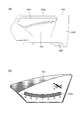
- FIG. 14 is a schematic view illustrating a part of the bed apparatus according to the embodiment. As shown in FIG. 14, the handrail 335g is obtained by the through hole 335h formed in the right side rail 330 of the foot.
- FIG. 15 is a schematic diagram which illustrates a part of bed apparatus which concerns on embodiment.
- FIG. 15 illustrates the goniometer 354 provided on the outer surface 350F of the left side rail 350.
- the goniometer 354 has a structure similar to that of the goniometer 324.
- the display unit 354a of the goniometer 354 can provide an overview of the angle.
- FIG. 16A and 16B are schematic views illustrating a part of the bed apparatus according to the embodiment.
- a through hole 375e (for example, a hook portion) is provided on the outer surface 370F of the footboard 370.
- the bed operation device 380 can be suspended in the through hole 375e.
- the through hole 375e penetrates the inner side surface 370G of the footboard 370.
- the bed operation device 380 can display various settings regarding the bed 310B and the weight of the user.
- a “home button” is provided as a “physical button” in the bed operation device 380.
- An example of the bed operating device 380 will be described later.
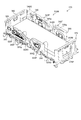
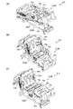
- 17(a) to 17(c) are schematic perspective views illustrating the operation of the bed apparatus according to the embodiment. These figures exemplify the state when the mattress 390M is not provided.
- the frame 390F is attached to the base frame 390B.
- a back bottom 70a back section
- a knee bottom 70b upper leg section
- a foot bottom 70c lower leg section
- the like are provided on the frame 390F.
- a waist bottom 70e is provided.
- the casters 390C may be provided on the base frame 390B.
- the angle (tilt) of the frame 390F can be changed.
- the tilt may include a left-right tilt as well as a front-back tilt.
- the respective angles of the back bottom 70a, the knee bottom 70b, and the foot bottom 70c can be changed.
- the angles of the head right side rail 320 and the head left side rail 340 change according to the change of the angle of the back bottom 70a.
- the head right side rail 320 and the head left side rail 340 are follow-up side rails.
- the state of FIG. 17B corresponds to the Cardiac position.
- the foot right side rail 330 and the foot left side rail 350 are in the “upper state”.
- the foot right side rail 330 and the foot left side rail 350 can be in the “down state”.
- the height of the bed 310B can be changed.
- the height corresponds to the distance between the upper surface of the bed 310B (for example, the upper surface of the bottom) and the floor surface, for example.
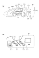
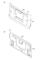
- FIG. 18A and 18B are schematic perspective views illustrating the usage state of the bed apparatus according to the embodiment.
- FIG. 18A illustrates a state where the bed 310B is low.
- a caregiver or the like 398 (for example, a caregiver or a medical worker) can operate the bed operation device 380 with the bed operation device 380 removed from the hook portion (for example, the through hole 325e of the right side head rail 320).
- FIG. 18B illustrates a state in which the bed 310B is high.
- a caregiver 399 or the like can operate the bed operation device 380 while the bed operation device 380 is attached to the hook portion.
- the bed operation device 380 is attached to, for example, three hook portions.
- the three hook portions are a through hole 325e of the head right side rail 320, a through hole 345e of the head left side rail 340, and a through hole 375e of the foot board 370.
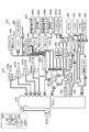
- FIG. 19 is a schematic view illustrating the bed apparatus according to the embodiment.
- a control box 410 is provided in the bed apparatus 310.
- various devices are provided in the bed device 310.
- Various devices include a junction box 420, a membrane switch 430, a leglight 440, a side rail sensor 450 (SR sensor), a caster lock sensor 455 (CL sensor), a nurse call 457a, a nurse call 457b, a nurse call relay unit 458, a scale.
- the unit 460, the load cell 465, the actuator 470, the battery 475, etc. are included. Some of the various devices may be omitted.
- the control box 410 can be connected to various devices. The connection between the control box 410 and various devices is made directly or via the junction box 420.
- the control box 410 controls the bed operation and various functions.
- the control box 410 serves as a master for serial communication in the bed apparatus 310.
- the control box 410 is provided with a plug 410P (for example, a 3-pin plug). Electric power is supplied to the control box 410 from the plug 410P. Electric power is supplied from the control box 410 to various devices.
- a plug 410P for example, a 3-pin plug. Electric power is supplied to the control box 410 from the plug 410P. Electric power is supplied from the control box 410 to various devices.
- the junction box 420 relays the connection between the control box 410 and various other devices.
- the membrane switch 430 includes membrane switches 430a and 430b for medical personnel. These membrane switches correspond to the switch units 323 and 343. Membrane switch 430 includes patient membrane switches 430c and 430d. These membrane switches correspond to the switch units 327 and 347.
- the medical worker membrane switch 430a and the patient membrane switch 430c are connected to the junction box 420 via the relay unit 431a.
- the membrane switch 430b for medical workers and the membrane switch 430d for patients are connected to the junction box 420 via the relay unit 431b.
- Bed operation buttons are provided on the membrane switches 430a and 430b for medical staff.
- the bed operation buttons are cardiac operation buttons (for example, interlocking operation buttons), extension/reverse extension buttons, kind motion operation buttons (for example, other interlocking operation buttons), CPR buttons, nurse calls. Includes buttons, patient membrane switch inhibit buttons, and all switch inhibit buttons. The operation described with respect to the switch units 323 and 343 is performed by these bed operation buttons.
- Bed operation buttons are provided on the patient membrane switches 430c and 430d.
- the bed operation buttons include the back bottom operation button, the knee bottom operation button, and the nurse call button.
- the patient membrane switches 430c and 430d may include charging terminals and the like.
- the bed operation button is provided at an intermediate position in the vertical direction. If the bed operation button is at the bottom, it is difficult to operate. If the bed operation button is at the top, it may be operated accidentally. Since the bed operation button is located at an intermediate position in the up-down direction, the operation becomes easy, and erroneous operation can be suppressed.
- the footlight button corresponds to the switches 323q and 343q.
- the footlight 440 illuminates.
- the foot lamp 440 illuminates the floor surface from the end of the bed 310B.
- the leg lights 440 are provided, for example, one on each side of the bed 310B.
- the leg lights 440 are provided, for example, at the left and right ends on the back side (lower side) of the waist bottom 70e.
- the leg lights 440 may be provided in other parts such as the back bottom 70a, the knee bottom 70b, and the foot bottom 70c (see FIG. 17B and the like).
- the leglight 440 is repeatedly turned off, dimly turned on, brightly turned on, and turned off.
- the leg light 440 is turned on by a medical staff. For example, when the user frequently goes to the toilet, the medical staff turns on the leglight 440 before the user goes to bed. For example, when a bed leaving is detected, or when a nurse call occurs, the medical staff turns on the leglight 440.
- the leg light 440 is turned on. At this time, the room is often dark. When the leglights 440 suddenly turn on brightly, people sleeping in the vicinity are annoyed. By turning on the light at first, annoyance is suppressed.
- the side rail sensor 450 detects whether or not each side rail is raised.
- Four siderail sensors 450 are provided.
- the four side rail sensors 450 include a head right side rail sensor, a head left side rail sensor, a foot right side rail sensor, and a foot left side rail sensor.
- the detection result is displayed on the terminal of the nurse station, for example.
- the detection result may be displayed on the bed operation device 380.
- a warning sound may be generated based on the detection result.
- As the side rail sensor 450 for example, a magnetic sensor or an atmospheric pressure sensor is used. Other sensors may be used as the side rail sensor 450.
- the caster lock sensor 455 detects whether or not the caster 390C is locked.
- a magnetic sensor is used as the caster lock sensor 455, for example.
- the caster 390C is provided with a bar or the like interlocking with the lock or unlock of the caster 390C.
- the locked state of the caster 390C can be detected by detecting the state of the bar.
- the detection result of the caster lock sensor 455 is displayed on the terminal of the nurse station, for example.
- the detection result may be displayed on the bed operation device 380.
- a warning sound may be generated based on the detection result of the caster lock sensor 455.
- the nurse call 457a is connected to the junction box 420.
- the nurse call 457b is connected to the nurse call relay unit 458.
- the nurse call relay unit 458 enables cooperation with a nurse call (for example, nurse call 457b) provided in hospitals and facilities.
- Nurse calls 457a and 457b are domestic or foreign nurse calls.
- the nurse call 457a is made in a foreign country.
- the nurse call 457b is made in Japan.
- the load cells 465 are provided at the four corners of the bed 310B. Four load cells 465 are used.
- the load cell 465 and the scale unit 460 can measure the weight of the user.
- the actuator 470 includes a height changing actuator 470a (“HLACT”), a knee bottom 70b actuator 470b (“knee ACT”), a back bottom 70a actuator 470c (CPR-equipped “back ACT”), and The height changing actuator 470d (“HLACT”) and the like are included.
- the actuators 470a and 470d include load sensors.
- the actuator 470c for the back bottom 70a includes a mechanical mechanism (hereinafter, referred to as a manual CPR mechanism) for performing a lowering operation manually.
- the manual CPR mechanism allows the back bottom 70a to be manually lowered in an emergency.
- a dedicated lever or the like is provided, and by operating this lever, the back bottom 70a can be manually lowered to obtain a posture for CPR.
- the brake plate of the actuator 470c for the back bottom 70a can be manually displaced. As a result, the brake of the actuator 470c is released, and the back bottom 70a is lowered by its own weight.
- the actuator 470 serves as a drive source for adjusting the movable part included in the bed 310B.
- the actuator 470 operates the movable portion via the link mechanism or the like by the operation of the telescopic rod.
- a position sensor is provided for each of the actuators. The position information is read by the control box 410.
- the load sensor of the actuator 470 may determine the movement of the user (patient, etc.) on the bed 310B (including, for example, leaving the bed).
- the battery 475 supplies electric power during a power failure or during transportation of the bed 310B.
- the desired operation can be obtained even in the situation where there is no power supply.
- a switch for charging/not charging the battery 475 may be provided. Charging may be possible as long as power (AC power) is supplied to the bed 310B regardless of the state of the changeover switch.
- the bed apparatus 310 when the bed apparatus 310 is driven by an AC power source, power is supplied from the control box 410 to the battery 475, the air mattress control unit 482 and the USB charger 488 (see FIG. 19).
- power is supplied from the battery 475 to the control box 410, the air mattress control unit 482, and the USB charger 488.
- the bed 310B When power is not supplied from the AC power supply and power is not supplied from the battery 475, the bed 310B does not operate.
- a sleep sensor 481, an air mattress control unit 482, and a bed operation apparatus 380 are provided in the bed apparatus 310.
- a hand switch 483 may be provided in the bed apparatus 310.
- the sleep sensor 481 measures the sleep status of the user (patient, etc.) of the bed 310B.
- the sleep status measurement result and the sleep history may be output (for example, displayed) to the bed operation device 380.
- control box 410 is provided with a connector for the air mattress control unit 482.
- the interlocking operation may be performed according to the posture of the bed 310B.
- the interlocking operation may differ depending on the type of air mattress.
- the bed operation device 380 may set and change the operation of the air mattress.
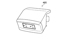
- the bed device 310 is further provided with an auxiliary outlet 485.
- two auxiliary outlets 485 are provided.
- the auxiliary outlet 485 is a plug receiving device.
- the auxiliary outlet 485 includes a plug 485P.
- the plug 485P is a plug that meets medical standards.
- the plug 485P is a 3-pin plug.
- the plug 485P is provided separately from the plug 410P of the control box 410.
- the bed apparatus 310 may include a USB charger 488 (see FIG. 19).
- the USB charger 488 corresponds to the USB terminal 327u (or 347u).
- the USB charger 488 supplies power to a device compatible with USB charging.
- the number of ports of the USB charger 488 may be one.
- the output rating of the USB charger 488 is DC 5V/1A.
- the port is provided on the patient membrane switch 430c on the right siderail.
- the bed device 310 may include an error display LED.
- the error display LED corresponds to the displays 323t and 343t.
- the bed device 310 may detect that the user of the bed 310B has left the bed. For example, leaving the bed is detected by the load cell 465. For example, the leaving sensor is detected by a load sensor incorporated in the actuator. Information about leaving the bed is transmitted to the nurse call system and output to the terminal of the nurse station. The information regarding leaving the bed may be output to the bed operation device 380. The output of information regarding leaving the bed may include, for example, a visual stimulus such as a lamp or an auditory stimulus such as a warning sound.
- the bed operation device 380 is connected to the bed 310B.
- the bed operation device 380 can set and display the settings related to the bed 310B. It is possible to switch the display language on the bed operation device 380. For example, it is possible to display in Japanese, English, Chinese or Portuguese.
- the bed operation device 380 is attached to, for example, the left and right side rails or the footboard 370.
- the maximum number of bed operation devices 380 provided in the bed device 310 is 3, for example.
- one bed operation device 380 or one hand switch 483 (described later) is connected to the bed 310B.
- one bed operation device 380 and one hand switch 483 are connected to the bed 310B.
- two bed operating devices 380 are connected to the bed 310B.
- two bed operation devices 380 and one hand switch 483 are connected to the bed 310B.
- three bed operation devices 380 are connected to the bed 310B.
- FIG. 20A and 20B are schematic views illustrating a part of the bed apparatus according to the embodiment.
- FIG. 20A illustrates the bed operating device 380 mainly provided on the head side rail (the head right side rail 320 or the head left side rail 340).
- the bed operation device 380 includes a display input unit 380D.
- the bed operation device 380 is provided with a home button 380h.
- various displays can be made on the display input unit 380D.
- the display input unit 380D can display the posture of the bed 310B and the weight of the user.
- the display input unit 380D allows setting of the bed leaving sensor.
- a display regarding the sleep sensor 481 can be performed by the display input unit 380D.
- the display input unit 380D allows the operation of the air mattress. An error can be displayed by the display input unit 380D.
- FIG. 21A and 21B are schematic views illustrating a part of the bed apparatus according to the embodiment.
- FIG. 21A illustrates the bed operation device 380 mainly provided on the footboard 370.
- the bed operation device 380 includes a display input unit 380D.
- the bed operation device 380 is provided with an up button 380a, a down button 380b, and a CPR button 380c.
- the up button 380a or the down button 380b moves up or down the movable part of the bed 310B.
- the CPR button 380c the posture is changed to CPR.
- various displays can be made on the display input unit 380D.
- the display input unit 380D can operate the bed 310B.
- the bed operation includes, for example, cardiac operation, tilting operation, interlocking operation (kind operation), raising and lowering the back, raising and lowering the knee, and raising and lowering the height.
- the display input unit 380D can display the weight of the user.
- the display input unit 380D allows setting of the bed leaving sensor.
- a display regarding the sleep sensor 481 can be performed by the display input unit 380D.
- the display input unit 380D allows the operation of the air mattress. An error can be displayed by the display input unit 380D.
- FIG. 22 is a schematic view illustrating a part of the bed apparatus according to the embodiment.
- FIG. 22 illustrates the hand switch 483.
- the hand switch 483 includes switch pairs 483a to 483d.
- Switch pair 483a includes a switch for raising or lowering for "interlocking" operation.
- Switch pair 483b includes a switch for raising or lowering for "back raising” movement.
- Switch pair 483c includes a switch for raising or lowering for a "foot lift” action.
- the switch pair 483d includes a switch for raising or lowering regarding the “height” changing operation.
- the angle or height may be displayed on the display portion 483D of the hand switch 483.
- the hand switch 483 is connected to, for example, the control box 410 by a cable 483e or the like.
- FIG. 23 is a schematic perspective view illustrating a part of the bed apparatus according to the embodiment.
- FIG. 23 illustrates an auxiliary outlet 485 (for example, a plug receiving device). Plugs of electronic devices used around the bed 310B can be connected to the auxiliary outlet 485.
- the plug 485P of the auxiliary outlet 485 is provided separately from the plug 410P of the control box 410.
- the auxiliary outlet 485 has two sets of plug receivers (plug insertion holes). The two sets of plug receivers are arranged side by side.
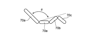
- FIG. 24 is a schematic view illustrating a part of the bed apparatus according to the embodiment.
- FIG. 24 illustrates the back bottom 70a, the knee bottom 70b, the foot bottom 70c, and the waist bottom 70e.
- the angles of the back bottom 70a, the knee bottom 70b, and the foot bottom 70c can be changed. It is controlled so that the angle between the bottoms does not fall below a predetermined value (for example, 90 degrees).
- a predetermined value for example, 90 degrees
- the angle between the line connecting the lower end of the back bottom 70a and the upper end of the knee bottom 70b (broken line in FIG. 24) and the back bottom 70a is controlled to be a predetermined value (for example, 90 degrees) or less.
- the angle is made equal to or less than a predetermined value.
- the operation angle of the back bottom 70a is, for example, 0 degrees to 70 degrees.
- the operation angle of the knee bottom 70b is 0 degrees or more and 25 degrees or less.
- the operating range of "height" is, for example, 43 cm.
- the floor height may vary depending on the bed frame. The floor height range is, for example, 30 cm to 73 cm, 32.5 cm to 75.5 cm, or 35 cm to 78 cm.
- the operating angle of the bottom tilt is -15 to 15 degrees.
- the tilting operation is performed after the height is adjusted to the height of “minimum floor height+3 cm”.
- the operations are performed in the following order. At that time, if the simultaneous operation is possible, the simultaneous operation may be performed.
- the stroke of the actuator 470c (“back ACT”) for the back bottom 70a is operated to the lower limit.
- the lower limit of the actuator 470c is reached within 30 seconds after the button for the electric CPR operation is pressed.
- the tilting operation is performed and the tilt angle becomes 0 degree.
- height adjustment is performed and the height becomes the minimum floor height.
- the minimum floor height is, for example, “temporary stop height”.
- the knee bottom 70b is moved to 0 degree.
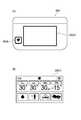
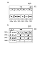
- FIG. 25A and 25B are schematic views illustrating a part of the bed apparatus according to the embodiment. These drawings exemplify the display input unit 380D of the bed operation device 380.
- FIG. 25A illustrates a case where the display input unit 380D is the bed operation screen 381.
- FIG. 25B illustrates a case where the display input unit 380D is the actuator individual operation prohibition screen 383 (bed setting screen).
- buttons 382a to 382f are provided. These buttons are, for example, input acceptance areas in the touch input device. By touching these buttons, bed operation is performed.
- the cardiac operation is performed by the button 382a.
- the tilt operation is performed by the button 382b.
- a linked operation (“kind operation”) is performed by the button 382c.
- the back movement is performed by the button 382d.
- a knee operation (change of knee angle) is performed by the button 382e.
- a height operation (change of height) is performed by the button 382f. For example, when raising the height of the bed 310B, pressing the button 382d and then pressing the lift button 380a moves the bed 310B.
- the bed 310B moves while pressing the up button 380a. For example, when lowering the height of the bed, if the button 382f is pressed and then the lowering button 380b is pressed, the height of the bed 310B is lowered while the lowering button 380b is being pressed.
- the display input unit 380D can be moved to the actuator individual operation prohibition screen 383 (bed setting screen).
- the actuator individual operation prohibition screen 383 bed setting screen.
- the back motion, knee motion, height motion, and tilt motion can be individually prohibited.
- the display input area 383b By operating the display input area 383b, all operations can be prohibited or the operation prohibition can be released.
- the display input area 383c By operating the display input area 383c, the operation of the hand switch 483 can be prohibited or the operation prohibition can be released.
- back movements are prohibited, cardiac movements, interlocking movements and back movements are prohibited.
- the Cardiac movement, the interlocking movement, and the knee movement are prohibited.
- the height motion is prohibited, the Cardiac motion, the tilt motion, and the height motion are prohibited.
- the tilting motion is prohibited, the Cardiac motion and the tilting motion are prohibited.
- the actuator 470 (such as 470a to 470d (see FIG. 19)) may be selectively (individually) “inhibited”. The release of the “operation prohibited” of the actuator 470 is released by the bed operation device 380.
- the prohibition of the operation of the actuator 470, the prohibition of the operation of the hand switch 483, or the prohibition of all the operations are managed independently. For example, when the individual operation of the actuator 470 is prohibited, the “all operation prohibited” is set, and thereafter, even if the “all operation prohibited” is released, the individual operation prohibition of the actuator 470 remains.
- a buzzer sounds and the prohibit LED (eg, display 323t and 343t) of the membrane switch blinks. If you don't hear a buzzer, you don't know if the button is banned or broken. A buzzer sounds to indicate that the button is prohibited.
- the hand switch 483 When the prohibited button on the hand switch 483 is pressed, the hand switch 483 sounds. When a prohibited button on the membrane switch is pressed, for example, the junction box 420 sounds.
- the membrane switch for medical staff or the bed operation device 380 By operating the membrane switch for medical staff or the bed operation device 380, the operation of the membrane switch for patients and the hand switch 483 can be disabled. The operation prohibition can be released if the medical worker membrane switch or the bed operation device 380 is connected.
- All operations can be prohibited by operating the membrane switch for medical staff or the bed operating device 380 (“All operations prohibited”). This operation prohibition can be released if either the membrane switch for medical staff or the bed navigation is connected.
- the bed operation device 380 is not connected to the bed 310B, or if there is a partial failure (communication failure), the “all operations prohibited” is released. In this case, for example, it can be operated by the hand switch 483. If the user does not want to operate it, the hand switch 483 may be removed. When the prohibited button is pressed, a buzzer sounds and the prohibit LED of the membrane switch blinks.
- the operation speed can be changed by operating the display input area 383d illustrated in FIG. 25(b).
- the speed of various operations can be changed in multiple stages (eg, two stages).
- History of various operations of the bed apparatus 310 may be stored.
- the history is stored in a memory such as the control box 410.
- the memory for storing the history may be provided in the junction box 420, the hand switch 483, or the like.
- the memory in which the history is stored may be provided in the bed operation device 380.
- Information about history is not reset by powering on/off.
- the history information includes, for example, the operation history of the control box 410, the operation history of the actuator 470, the operation history of the hand switch 483, the operation content history, the failure history, and the separated floor history.
Abstract
According to an embodiment, this bed apparatus includes a frame, side rails, and holding parts. The holding parts are fixed to the frame. The holding parts respectively hold the side rails so as to be switchable between a first positional state in which the side rails are at a first position, and a second positional state in which the side rails are at a second position lower than the first position. Each holding part includes: a lock part that locks the corresponding side rail in the first positional state; a cover part that at least partially covers the lock part; a lever part that is operated in order to release the lock of the lock part; and a stopper part that increases the difficulty of the operation by which the lever part releases the lock. It is thus possible to provide a bed apparatus that can minimize the chance of releasing the lock by mistake.
Description
本発明の実施形態は、ベッド装置に関する。
The embodiment of the present invention relates to a bed apparatus.
例えば、ベッドにおいて、上下方向に移動できるサイドレールが設けられる。サイドレールが上にあるときに、ベッドからの使用者の落下が抑制できる。一方、サイドレールが下にあるときに、ベッドからの使用者の離床を促すことができる。サイドレールの上下動作をロックすることで、より安全になる。ロックを誤って解除することを抑制することが望まれる。
For example, a bed has side rails that can move vertically. When the side rail is on the upper side, the user can be prevented from falling from the bed. On the other hand, when the side rail is below, the user can be encouraged to leave the bed. It becomes safer by locking the vertical movement of the side rail. It is desirable to prevent accidental unlocking.
本発明の実施形態は、ロックを誤って解除することを抑制できるベッド装置を提供する。
The embodiment of the present invention provides a bed apparatus that can prevent accidental unlocking.
本発明の実施形態によれば、ベッド装置は、フレーム、サイドレール及び保持部を含む。前記保持部は、前記フレームに固定される。前記保持部は、前記サイドレールが第1位置にある第1位置状態と、前記サイドレールが前記第1位置よりも低い第2位置にある第2位置状態と、に切り替え可能に、前記サイドレールを保持する。前記保持部は、前記サイドレールを前記第1位置状態にロックするロック部と、前記ロック部の少なくとも一部をカバーするカバー部と、前記ロック部のロックを解除するために操作されるレバー部と、前記レバー部がロックを解除する操作を困難にするストッパ部と、含む。
According to the embodiment of the present invention, the bed apparatus includes a frame, side rails, and a holding unit. The holding part is fixed to the frame. The holding portion is switchable between a first position state in which the side rail is in a first position and a second position state in which the side rail is in a second position lower than the first position. Hold. The holding portion includes a lock portion that locks the side rail in the first position state, a cover portion that covers at least a part of the lock portion, and a lever portion that is operated to unlock the lock portion. And a stopper portion that makes it difficult to release the lock by the lever portion.
本発明の実施形態によれば、ロックを誤って解除することを抑制できるベッド装置が提供できる。
According to the embodiment of the present invention, it is possible to provide a bed apparatus that can prevent the lock from being accidentally released.
以下に、本発明の各実施の形態について図面を参照しつつ説明する。
本願明細書と各図において、既出の図に関して前述したものと同様の要素には同一の符号を付して詳細な説明は適宜省略する。 Each embodiment of the present invention will be described below with reference to the drawings.
In the specification and the drawings of the application, components similar to those described in regard to a drawing thereinabove are marked with like reference numerals, and a detailed description is omitted as appropriate.
(第1実施形態)
図1(a)~図1(c)は、第1実施形態に係るベッド装置を例示する模式的斜視図である。
図1(a)及び図1(b)は、ベッド装置110における異なる状態を例示している。図1(c)は、ベッド装置110の一部を拡大して例示している。 (First embodiment)
1A to 1C are schematic perspective views illustrating the bed apparatus according to the first embodiment.
1A and 1B illustrate different states of thebed apparatus 110. FIG. 1C illustrates a part of the bed apparatus 110 in an enlarged manner.
図1(a)~図1(c)は、第1実施形態に係るベッド装置を例示する模式的斜視図である。
図1(a)及び図1(b)は、ベッド装置110における異なる状態を例示している。図1(c)は、ベッド装置110の一部を拡大して例示している。 (First embodiment)
1A to 1C are schematic perspective views illustrating the bed apparatus according to the first embodiment.
1A and 1B illustrate different states of the
図1(a)に示すように、実施形態に係るベッド装置110は、フレーム75、サイドレール72、及び、保持部50を含む。保持部50は、サイドレール72を保持する。
As shown in FIG. 1A, the bed apparatus 110 according to the embodiment includes a frame 75, side rails 72, and a holding unit 50. The holding unit 50 holds the side rail 72.
図1(a)の例では、複数のサイドレール(サイドレール72及び別のサイドレール72A)と、複数の保持部(保持部50及び別の保持部50A)が設けられている。別のサイドレール72Aは、サイズ及び設けられる位置を除いて、サイドレール72と同様として良い。別の保持部50Aは、別のサイドレール72Aを保持する。図1(a)に示すように、サイドレール72及び保持部50などは、ベッドの左右のそれぞれに設けられても良い。以下では、1つのサイドレール72、及び、1つの保持部50について説明する。
In the example of FIG. 1A, a plurality of side rails (side rail 72 and another side rail 72A) and a plurality of holding portions (holding portion 50 and another holding portion 50A) are provided. The other side rail 72A may be the same as the side rail 72 except for the size and the position where it is provided. Another holding part 50A holds another side rail 72A. As shown in FIG. 1A, the side rail 72, the holding portion 50, and the like may be provided on each of the left and right sides of the bed. Below, one side rail 72 and one holding part 50 will be described.
フレーム75は、例えば、ベースフレーム75Bに固定される。フレーム75の上に、ボトム(図示しない)が設けられ、その上に、マットレス78Mが設けられる。マットレス78Mの上に、ベッド装置110の使用者が横たわることが可能である。
The frame 75 is fixed to the base frame 75B, for example. A bottom (not shown) is provided on the frame 75, and a mattress 78M is provided thereon. A user of the bed apparatus 110 can lie on the mattress 78M.
例えば、ベッド装置110は、ヘッドボード78A及びフットボード78Bを含む。ヘッドボード78Aからフットボード78Bへの方向は、「長手方向」に対応する。「長手方向」と交差する方向は、「幅方向」に対応する。「幅方向」は、例えば、使用者がマットレス78Mの上に寝ているときの「左右方向」に対応する。
For example, the bed apparatus 110 includes a headboard 78A and a footboard 78B. The direction from the headboard 78A to the footboard 78B corresponds to the "longitudinal direction". The direction intersecting the "longitudinal direction" corresponds to the "width direction". The “width direction” corresponds to, for example, the “left-right direction” when the user is sleeping on the mattress 78M.
フレーム75は、例えば、「長手方向」に延びる。
The frame 75 extends, for example, in the “longitudinal direction”.
例えば、保持部50は、フレーム75に固定される。保持部50の1つの部分は、フレーム75に固定される。保持部50の別の部分が、サイドレール72と連結される。これにより、保持部50は、サイドレール72を保持する。
For example, the holding unit 50 is fixed to the frame 75. One part of the holding part 50 is fixed to the frame 75. Another portion of the holding portion 50 is connected to the side rail 72. As a result, the holding unit 50 holds the side rail 72.
実施形態においては、保持部50は、サイドレール72を複数の状態で保持する。図1(a)は、第1位置状態SP1を例示している。図1(b)は、第2位置状態SP2を例示している。第1位置状態SP1においては、サイドレール72が第1位置にある。第2位置状態SP2においては、サイドレール72は、第2位置にある。第2位置は、第1位置よりも低い。このように、保持部50は、第1位置状態SP1と第2位置状態SP2とに切り替え可能に、サイドレール72を保持する。第1位置状態SP1(上げ状態)におけるサイドレール72の上端の位置は、マットレス78Mの上面の位置よりも高い。第2位置状態SP2(下げ状態)におけるサイドレール72の上端の位置は、マットレス78Mの上面の位置よりも低い。
In the embodiment, the holding unit 50 holds the side rail 72 in a plurality of states. FIG. 1A illustrates the first position state SP1. FIG. 1B illustrates the second position state SP2. In the first position state SP1, the side rail 72 is in the first position. In the second position state SP2, the side rail 72 is in the second position. The second position is lower than the first position. In this way, the holding portion 50 holds the side rail 72 so as to be switchable between the first position state SP1 and the second position state SP2. The position of the upper end of the side rail 72 in the first position state SP1 (raised state) is higher than the position of the upper surface of the mattress 78M. The position of the upper end of the side rail 72 in the second position state SP2 (down state) is lower than the position of the upper surface of the mattress 78M.
図1(c)に示すように、保持部50は、カバー部52、レバー部53及びストッパ部54を含む。保持部50は、後述するロック部51(図2(a)など)参照)をさらに含む。この例では、カバー部52に凹部52aが設けられている。レバー部53の少なくとも一部は、カバー部52の凹部52aに設けられる。
As shown in FIG. 1C, the holding part 50 includes a cover part 52, a lever part 53, and a stopper part 54. The holding unit 50 further includes a lock unit 51 (see FIG. 2A and the like) described later). In this example, the cover 52 is provided with a recess 52a. At least a part of the lever portion 53 is provided in the recess 52a of the cover portion 52.
この例では、ストッパ部54の少なくとも一部は、凹部52aの中にある。そして、ストッパ部54の少なくとも一部は、凹部52aの中において、レバー部53の下にある。
In this example, at least a part of the stopper 54 is in the recess 52a. Then, at least a part of the stopper portion 54 is below the lever portion 53 in the recess 52a.
ロック部51は、サイドレール72を第1位置状態SP1にロックする。カバー部52は、ロック部51の少なくとも一部をカバー。レバー部53は、ロック部51のロックを解除するために操作される。ストッパ部54は、レバー部53がロックを解除する操作を困難にする。
The lock part 51 locks the side rail 72 in the first position state SP1. The cover portion 52 covers at least a part of the lock portion 51. The lever portion 53 is operated to unlock the lock portion 51. The stopper portion 54 makes it difficult for the lever portion 53 to release the lock.
以下、保持部50のこれらの部分の例について説明する。
Hereinafter, examples of these parts of the holding unit 50 will be described.
図2(a)~図2(d)及び図3は、第1実施形態に係るベッド装置を例示する模式的断面図である。
これらの図は、図1(c)のA1-A2線断面に対応する断面図である。 2A to 2D and FIG. 3 are schematic cross-sectional views illustrating the bed apparatus according to the first embodiment.
These figures are sectional views corresponding to the section taken along the line A1-A2 of FIG.
これらの図は、図1(c)のA1-A2線断面に対応する断面図である。 2A to 2D and FIG. 3 are schematic cross-sectional views illustrating the bed apparatus according to the first embodiment.
These figures are sectional views corresponding to the section taken along the line A1-A2 of FIG.
図2(a)に示すように、保持部50は、ロック部51、カバー部52、レバー部53及びストッパ部54を含む。図2(a)において、サイドレール72は、第1位置状態SP1(上げ状態)である。
As shown in FIG. 2A, the holding part 50 includes a lock part 51, a cover part 52, a lever part 53, and a stopper part 54. In FIG. 2A, the side rail 72 is in the first position state SP1 (raised state).
ロック部51は、ロック状態SLK(図2(a)参照)と、アンロック状態SUL(図2(d)参照)と、を有する。ロック部51がロック状態SLKのときに、ロック部51は、サイドレール72を第1位置状態SP1にロックする。この例では、ロック部51は、フック部51Aとピン部51Pを含む。ピン部51Pは、ロック部品58に固定されている。フック部51Aの1つの状態(ロック状態SLK)において、フック部51Aは、ピン部51Pにフックされている。これにより、ロック部51は、サイドレール72を第1位置状態SP1にロックする。
The lock unit 51 has a lock state SLK (see FIG. 2A) and an unlock state SUL (see FIG. 2D). When the lock portion 51 is in the locked state SLK, the lock portion 51 locks the side rail 72 in the first position state SP1. In this example, the lock portion 51 includes a hook portion 51A and a pin portion 51P. The pin portion 51P is fixed to the lock component 58. In one state (locked state SLK) of the hook portion 51A, the hook portion 51A is hooked on the pin portion 51P. As a result, the lock portion 51 locks the side rail 72 in the first position state SP1.
図2(a)に示すように、カバー部52は、ロック部51の少なくとも一部(前面部分)をカバーする。カバー部52によりロック部51の前面がカバーされることで、清拭性が増し、内部機構を隠すことができる。
As shown in FIG. 2A, the cover part 52 covers at least a part (front part) of the lock part 51. By covering the front surface of the lock part 51 with the cover part 52, the wiping property is improved and the internal mechanism can be hidden.
既に説明したように、レバー部53の少なくとも一部は、カバー部52の凹部52aに設けられている。ベッド装置110の使用者または介護者などは、レバー部53を触ることが可能である。
As described above, at least a part of the lever portion 53 is provided in the recess 52a of the cover portion 52. The user or caregiver of the bed apparatus 110 can touch the lever portion 53.
レバー部53は、複数の状態を有することができる。複数の状態は、例えば、非解除状態SUR(図2(a)参照)、及び、解除状態SRS(図2(d)参照)を含む。例えば、レバー部53が非解除状態SUR(図2(a)参照)のときに、ロック部51は、ロック状態SLKである。レバー部53が非解除状態SURのときには、ロック部51がアンロック状態SULに移行しない。後述するように、レバー部53が解除状態SRS(図2(d)参照)のときに、サイドレール72は、アンロック状態SULに移行可能である。
The lever part 53 can have a plurality of states. The plurality of states include, for example, a non-released state SUR (see FIG. 2A) and a released state SRS (see FIG. 2D). For example, when the lever portion 53 is in the non-released state SUR (see FIG. 2A), the lock portion 51 is in the locked state SLK. When the lever portion 53 is in the non-released state SUR, the lock portion 51 does not shift to the unlocked state SUL. As will be described later, when the lever portion 53 is in the released state SRS (see FIG. 2(d)), the side rail 72 can shift to the unlocked state SUL.
例えば、ストッパ部54も、複数の状態を有することができる。複数の状態は、第1状態ST1(図2(a)参照)、及び、第2状態ST2(図2(b)参照)を含む。ストッパ部54が第1状態ST1(図2(a)参照)のときに、ストッパ部54は、レバー部53が解除状態SRSに移行することを困難にする。ストッパ部54が第2状態ST2(図2(b)参照)のときに、ストッパ部54は、レバー部53が解除状態SRS(図2(d)参照)に移行可能にする。第1状態ST1は、ロック解除困難状態(またはロック解除禁止状態)である。第2状態ST2は、ロック解除移行可能状態である。
For example, the stopper portion 54 can also have a plurality of states. The plurality of states includes a first state ST1 (see FIG. 2A) and a second state ST2 (see FIG. 2B). When the stopper portion 54 is in the first state ST1 (see FIG. 2A), the stopper portion 54 makes it difficult for the lever portion 53 to shift to the release state SRS. When the stopper portion 54 is in the second state ST2 (see FIG. 2B), the stopper portion 54 allows the lever portion 53 to shift to the release state SRS (see FIG. 2D). The first state ST1 is a lock release difficulty state (or a lock release prohibition state). The second state ST2 is an unlockable state.
ストッパ部54が第1状態ST1であるときにレバー部53が解除状態SRSに移行することは、ストッパ部54が第2状態ST2であるときにレバー部53が解除状態SRSに移行することよりも困難である。ストッパ部54が第1状態ST1であるときよりも、ストッパ部54が第2状態ST2であるときに、レバー部53が解除状態SRSに移行し易い。
The transition of the lever portion 53 to the release state SRS when the stopper portion 54 is in the first state ST1 is more than the transition of the lever portion 53 to the release state SRS when the stopper portion 54 is in the second state ST2. Have difficulty. When the stopper portion 54 is in the second state ST2, the lever portion 53 is easier to shift to the release state SRS than when the stopper portion 54 is in the first state ST1.
例えば、図2(a)に示す状態において、レバー部53は、非解除状態SURである。そして、ストッパ部54は、第1状態ST1である。この例では、ストッパ部54がレバー部53の下部に実質的に接触するように、ストッパ部54は、上げ状態である。ストッパ部54がレバー部53の下部に実質的に接触しているため、使用者などの指は、ストッパ部54とレバー部53との間に誤って入ることが抑制される。ストッパ部54が第1状態ST1であることにより、使用者が、レバー部53を操作することが抑制できる。
For example, in the state shown in FIG. 2A, the lever portion 53 is in the non-released state SUR. The stopper 54 is in the first state ST1. In this example, the stopper portion 54 is in the raised state so that the stopper portion 54 substantially contacts the lower portion of the lever portion 53. Since the stopper portion 54 is substantially in contact with the lower portion of the lever portion 53, it is possible to prevent a finger of a user or the like from accidentally entering between the stopper portion 54 and the lever portion 53. Since the stopper portion 54 is in the first state ST1, it is possible to prevent the user from operating the lever portion 53.
図2(b)に示すように、例えば、介護者などの操作により、ストッパ部54は下方向に動くことができる。例えば、1つの軸を中心としてストッパ部54の端が回って、ストッパ部54が下げ状態となる。この状態が、ストッパ部54の第2状態ST2に対応する。
As shown in FIG. 2B, the stopper 54 can be moved downward by an operation of a caregiver, for example. For example, the end of the stopper portion 54 rotates around one axis, and the stopper portion 54 is in a lowered state. This state corresponds to the second state ST2 of the stopper portion 54.
第2状態ST2において、レバー部53とストッパ部54との間に、隙間が生じる。この隙間の幅(上下方向の距離)は、介護者の指が入る程度である。この隙間に手を入れることで、介護者などは、レバー部53の下部を触ることができる。ストッパ部54の第2状態ST2(図2(b)参照)において、レバー部53は、ロック部51のロック状態SLKを解除する解除状態SRS(図2(d)参照)に移行可能になる。
In the second state ST2, a gap is created between the lever portion 53 and the stopper portion 54. The width of this gap (the distance in the vertical direction) is such that the caregiver's finger can enter. By putting a hand in this gap, a caregiver or the like can touch the lower portion of the lever portion 53. In the second state ST2 (see FIG. 2B) of the stopper portion 54, the lever portion 53 can shift to the release state SRS (see FIG. 2D) that releases the lock state SLK of the lock portion 51.
この例では、図2(b)の状態から図2(d)の状態の間に、別の状態(図2(c)の状態)が設けられている。図2(c)に示すように、ストッパ部54が第2状態ST2になった後で、保持部50(またはサイドレール72)がマットレス78M側に押されると、ロック部51のフック部51Aがピン部51Pから外れ易くなる。
In this example, another state (state of FIG. 2(c)) is provided between the state of FIG. 2(b) and the state of FIG. 2(d). As shown in FIG. 2C, when the holding portion 50 (or the side rail 72) is pushed toward the mattress 78M side after the stopper portion 54 is in the second state ST2, the hook portion 51A of the lock portion 51 is released. It becomes easy to come off from the pin portion 51P.
この後、図2(d)に示すように、介護者などの操作により、レバー部53の端が上方向に持ち上げられる。例えば、レバー部53の前端が、レバー部53の後側の軸を中心にして回る。これにより、ロック部51のフック部51Aがピン部51Pから外れる。ロック部51は、アンロック状態SULになる。このように、レバー部53が操作されることで、レバー部53は、解除状態SRSになり、ロック部51のロック状態SLKが解除される。
After that, as shown in FIG. 2D, the end of the lever portion 53 is lifted upward by an operation of a caregiver or the like. For example, the front end of the lever portion 53 rotates around the rear side shaft of the lever portion 53. As a result, the hook portion 51A of the lock portion 51 is disengaged from the pin portion 51P. The lock unit 51 is in the unlocked state SUL. In this way, by operating the lever portion 53, the lever portion 53 enters the unlocked state SRS, and the locked state SLK of the lock portion 51 is unlocked.
図3に示すように、ロック部51のロック状態SLKが解除されることで、サイドレール72は、下方向に移動することができる。この状態が、第2位置状態SP2に対応する。
As shown in FIG. 3, when the lock state SLK of the lock portion 51 is released, the side rail 72 can move downward. This state corresponds to the second position state SP2.
このように、実施形態においては、ストッパ部54がロック解除困難(または禁止)状態の第1状態ST1と、ロック解除移行可能状態の第2状態ST2と、を有する。これにより、例えば、ベッド装置110の使用者などが誤ってロックを解除することが抑制される。実施形態によれば、ロックを誤って解除することを抑制できるベッド装置を提供できる。
As described above, in the embodiment, the stopper portion 54 has the first state ST1 in which unlocking is difficult (or prohibited) and the second state ST2 in which unlocking can be performed. As a result, for example, the user of the bed apparatus 110 is prevented from accidentally unlocking. According to the embodiment, it is possible to provide a bed apparatus that can prevent accidental unlocking.
上記の例においては、ストッパ部54を下方向に動かした状態(図2(b)参照)の後に、保持部50(またはサイドレール72)がマットレス78M側に押される状態(図2(c)参照)がある。実施形態において、保持部50(またはサイドレール72)がマットレス78M側に押された後に、ストッパ部54が下方向に動かされても良い。
In the above example, after the stopper portion 54 has been moved downward (see FIG. 2B), the holding portion 50 (or the side rail 72) is pushed toward the mattress 78M (FIG. 2C). There is). In the embodiment, the stopper portion 54 may be moved downward after the holding portion 50 (or the side rail 72) is pushed toward the mattress 78M side.
実施形態において、ストッパ部54が第1状態ST1であるときのストッパ部54の少なくとも一部と、レバー部53の少なくとも一部と、の間の距離は、ストッパ部54が第2状態ST2であるときのストッパ部54の上記の少なくとも一部と、レバー部53の上記の少なくとも一部と、の間の距離よりも短い。
In the embodiment, the distance between at least part of the stopper part 54 and at least part of the lever part 53 when the stopper part 54 is in the first state ST1 is such that the stopper part 54 is in the second state ST2. Is shorter than the distance between the above-mentioned at least part of the stopper portion 54 and the above-mentioned at least part of the lever portion 53.
例えば、ストッパ部54が第1状態ST1である時において、ストッパ部54とレバー部53との間の距離は、例えば、8mm以下である。これにより、第1状態ST1において、ストッパ部54とレバー部53と間の空間に、指などが誤って入ることが抑制できる。これにより、ロック状態を維持させる第1状態ST1が安定する。
For example, when the stopper portion 54 is in the first state ST1, the distance between the stopper portion 54 and the lever portion 53 is, for example, 8 mm or less. This can prevent a finger or the like from accidentally entering the space between the stopper portion 54 and the lever portion 53 in the first state ST1. This stabilizes the first state ST1 that maintains the locked state.
ストッパ部54が第2状態ST2である時において、ストッパ部54とレバー部53との間の距離は、例えば、8mmを超える。これにより、第2状態ST2において、ストッパ部54とレバー部53と間の空間に、指などが入りやすくなり、レバー部53を操作し易くなる。
When the stopper portion 54 is in the second state ST2, the distance between the stopper portion 54 and the lever portion 53 exceeds, for example, 8 mm. As a result, in the second state ST2, it is easy for a finger or the like to enter the space between the stopper portion 54 and the lever portion 53, and the lever portion 53 can be easily operated.
(他の実施形態)
図4(a)、図4(b)、図5(a)、図5(b)、図6(a)、図6(b)、図7(a)、図7(b)、図8(a)及び図8(b)は、他の実施形態に係るベッド装置を例示する模式的斜視図である。
これらの図は、保持部50を例示している。保持部50を除く部分は、図1(a)及び図1(b)に関して説明した通りである。これらの図において、ロック部51は、カバー部52にカバーされており、見えない。 (Other embodiments)
4(a), 4(b), 5(a), 5(b), 6(a), 6(b), 7(a), 7(b), 8 FIG. 8A and FIG. 8B are schematic perspective views illustrating a bed apparatus according to another embodiment.
These drawings exemplify the holdingunit 50. The portions other than the holding portion 50 are as described with reference to FIGS. 1(a) and 1(b). In these figures, the lock portion 51 is covered with the cover portion 52 and is not visible.
図4(a)、図4(b)、図5(a)、図5(b)、図6(a)、図6(b)、図7(a)、図7(b)、図8(a)及び図8(b)は、他の実施形態に係るベッド装置を例示する模式的斜視図である。
これらの図は、保持部50を例示している。保持部50を除く部分は、図1(a)及び図1(b)に関して説明した通りである。これらの図において、ロック部51は、カバー部52にカバーされており、見えない。 (Other embodiments)
4(a), 4(b), 5(a), 5(b), 6(a), 6(b), 7(a), 7(b), 8 FIG. 8A and FIG. 8B are schematic perspective views illustrating a bed apparatus according to another embodiment.
These drawings exemplify the holding
図4(a)及び図4(b)に示すベッド装置111においては、ストッパ部54は、板状部を含む。板状部(ストッパ部54)には、孔54Hが設けられている。孔54Hの第1部分54Haは、第1方向(例えば重力の方向)に延びている。孔54Hの第2部分54Hbは、第1方向と交差する方向(例えば、フレーム75に沿う方向)に延びている。第2部分54Hbの位置は、第1部分54Haの上端の位置よりも下である。孔54Hにピン54Pが挿入されている。
In the bed apparatus 111 shown in FIGS. 4A and 4B, the stopper portion 54 includes a plate-shaped portion. A hole 54H is provided in the plate-shaped portion (stopper portion 54). The first portion 54Ha of the hole 54H extends in the first direction (for example, the direction of gravity). The second portion 54Hb of the hole 54H extends in a direction intersecting the first direction (for example, a direction along the frame 75). The position of the second portion 54Hb is lower than the position of the upper end of the first portion 54Ha. The pin 54P is inserted into the hole 54H.
図4(a)においては、ストッパ部54は、第1状態ST1(ロック解除困難(禁止)状態)である。このとき、ピン54Pは、孔54Hの第2部分54Hbにある。これにより、ストッパ部54の上端は、レバー部53の下端に近い状態で固定される。ストッパ部54により、レバー部53を操作することができなくなる。
In FIG. 4A, the stopper portion 54 is in the first state ST1 (lock release difficult (prohibited) state). At this time, the pin 54P is in the second portion 54Hb of the hole 54H. Thereby, the upper end of the stopper portion 54 is fixed in a state close to the lower end of the lever portion 53. The stopper portion 54 prevents the lever portion 53 from being operated.
図4(b)においては、ストッパ部54は、第2状態ST2(ロック解除移行可能状態)である。このとき、ピン54Pは、孔54Hの第1部分54Haの上端にある。これにより、ストッパ部54の上端は、レバー部53の下端から離れる。これにより、レバー部53を操作することができる。
In FIG. 4B, the stopper portion 54 is in the second state ST2 (lock release shiftable state). At this time, the pin 54P is at the upper end of the first portion 54Ha of the hole 54H. As a result, the upper end of the stopper portion 54 separates from the lower end of the lever portion 53. Thereby, the lever portion 53 can be operated.
図5(a)及び図5(b)に示すベッド装置112においては、ストッパ部54は、詰め部材を含む。詰め部材(ストッパ部54)は、カバー部52の凹部52a内における、レバー部53の下の空間に詰めることができる。
In the bed apparatus 112 shown in FIGS. 5A and 5B, the stopper portion 54 includes a padding member. The filling member (stopper portion 54) can be filled in the space below the lever portion 53 in the recess 52a of the cover portion 52.
図5(a)においては、ストッパ部54は、第1状態ST1(ロック解除困難(禁止)状態)である。このとき、詰め部材(ストッパ部54)は、カバー部52の凹部52a内における、レバー部53の下の空間に挿入されている。詰め部材(ストッパ部54)により、レバー部53を操作することができなくなる。
In FIG. 5A, the stopper portion 54 is in the first state ST1 (lock release difficult (prohibited) state). At this time, the filling member (stopper portion 54) is inserted in the space below the lever portion 53 in the recess 52 a of the cover portion 52. The stuffing member (stopper portion 54) makes it impossible to operate the lever portion 53.
図5(b)においては、ストッパ部54は、第2状態ST2(ロック解除移行可能状態)である。このとき、詰め部材(ストッパ部54)は、カバー部52の凹部52aから取り外される。これにより、レバー部53を操作することができる。
In FIG. 5B, the stopper portion 54 is in the second state ST2 (lock release shiftable state). At this time, the filling member (stopper 54) is removed from the recess 52a of the cover 52. Thereby, the lever portion 53 can be operated.
図6(a)及び図6(b)に示すベッド装置113においては、ストッパ部54は、ヒンジ状である。ヒンジの一方の辺は、レバー部53に取り付けられる。ヒンジの他方の辺が、ストッパ部54に対応する。ヒンジの一方の辺と、ヒンジの他方の辺と、が、軸部54xにより回動可能な状態で接続される。
In the bed apparatus 113 shown in FIGS. 6A and 6B, the stopper portion 54 has a hinge shape. One side of the hinge is attached to the lever portion 53. The other side of the hinge corresponds to the stopper portion 54. One side of the hinge and the other side of the hinge are rotatably connected by the shaft portion 54x.
図6(a)においては、ストッパ部54は、第1状態ST1(ロック解除困難(禁止)状態)である。このとき、ストッパ部54により、カバー部52の凹部52a内における、レバー部53の下の空間が塞がれる。ストッパ部54により、レバー部53を操作することができなくなる。
In FIG. 6A, the stopper portion 54 is in the first state ST1 (lock release difficult (prohibited) state). At this time, the stopper 54 closes the space under the lever 53 in the recess 52 a of the cover 52. The stopper portion 54 prevents the lever portion 53 from being operated.
図6(b)においては、ストッパ部54は、第2状態ST2(ロック解除移行可能状態)である。このとき、ストッパ部54を上方向に回動させることで、レバー部53の下部を触ることができる。これにより、レバー部53を操作することができる。
In FIG. 6B, the stopper portion 54 is in the second state ST2 (lock release shiftable state). At this time, the lower portion of the lever portion 53 can be touched by rotating the stopper portion 54 upward. Thereby, the lever portion 53 can be operated.
図7(a)及び図7(b)に示すベッド装置114においては、ストッパ部54は、バー状部材54pを含む。バー状部材54pは、例えば、フレームの延びる方向に沿って延びる。バー状部材54pの一端は、第1部材54qに接続される。バー状部材54pの他端は、第2部材54rに接続される。第1部材54q及び第2部材54rのそれぞれの8は、カバー部52に設けられた孔52hに挿入され、回動可能なように支持されている。
In the bed device 114 shown in FIGS. 7A and 7B, the stopper portion 54 includes a bar-shaped member 54p. The bar-shaped member 54p extends, for example, along the extending direction of the frame. One end of the bar-shaped member 54p is connected to the first member 54q. The other end of the bar-shaped member 54p is connected to the second member 54r. Each 8 of the 1st member 54q and the 2nd member 54r is inserted in hole 52h provided in the cover part 52, and is rotatably supported.
図7(a)においては、ストッパ部54は、第1状態ST1(ロック解除困難(禁止)状態)である。このとき、バー状部材54pは、レバー部53の下の空間の前にある。バー状部材54pにより、レバー部53を操作することができなくなる。
In FIG. 7A, the stopper portion 54 is in the first state ST1 (lock release difficult (prohibited) state). At this time, the bar-shaped member 54p is in front of the space below the lever portion 53. The lever portion 53 cannot be operated by the bar-shaped member 54p.
図7(b)においては、ストッパ部54は、第2状態ST2(ロック解除移行可能状態)である。このとき、バー状部材54pを下方向に回動させることで、レバー部53の下部を触ることができる。これにより、レバー部53を操作することができる。
In FIG. 7B, the stopper portion 54 is in the second state ST2 (lock release shiftable state). At this time, the lower portion of the lever portion 53 can be touched by rotating the bar-shaped member 54p downward. Thereby, the lever portion 53 can be operated.
図8(a)及び図8(b)に示すベッド装置115においては、ストッパ部54は、カバー部52から取り外しが可能である。例えば、ストッパ部54は、機械的、電気的及び磁気的などの任意の方法で、カバー部52からの取り外しが可能にできる。例えば、ストッパ部54のカバー部52への取り付けは、例えば、ピンなどにより行われる。取り付けは、例えば、面状ファスナなどにより行われても良い。取り付けは、例えば、静電力などにより行われても良い。取り付けは、例えば、磁石などを用いて行われても良い。
In the bed apparatus 115 shown in FIGS. 8A and 8B, the stopper 54 can be removed from the cover 52. For example, the stopper portion 54 can be removable from the cover portion 52 by any mechanical, electrical, or magnetic method. For example, the stopper 54 is attached to the cover 52 with, for example, a pin. The attachment may be performed by, for example, a sheet fastener or the like. The attachment may be performed, for example, by electrostatic force. The attachment may be performed using, for example, a magnet.
図8(a)においては、ストッパ部54は、第1状態ST1(ロック解除困難(禁止)状態)である。このとき、ストッパ部54は、は、レバー部53の下の空間の前にある。ストッパ部54は、により、レバー部53を操作することができなくなる。
In FIG. 8A, the stopper portion 54 is in the first state ST1 (lock release difficult (prohibited) state). At this time, the stopper portion 54 is in front of the space below the lever portion 53. The stopper portion 54 makes it impossible to operate the lever portion 53.
図8(b)においては、ストッパ部54は、第2状態ST2(ロック解除移行可能状態)である。このとき、ストッパ部54は、取り外される。これにより、レバー部53を操作することができる。
In FIG. 8B, the stopper portion 54 is in the second state ST2 (lock release shiftable state). At this time, the stopper portion 54 is removed. Thereby, the lever portion 53 can be operated.
実施形態において、保持部50の構成(ロック部51、カバー部52、レバー部53及びストッパ部54の構成)は、種々の変形が可能である。
In the embodiment, the structure of the holding part 50 (the structure of the lock part 51, the cover part 52, the lever part 53, and the stopper part 54) can be variously modified.
上記のベッド装置110~115において、レバー部53の一部は、非解除状態SUR、解除状態SRS、及び、非解除状態SURと解除状態SRSとの間の少なくともいずれかにおいて、凹部52aの外にあっても良い(例えば、図2(d)参照)。この場合、ベッド装置110または112のように、ストッパ部54の少なくとも一部が、凹部52aの中にあることで、レバー部53の動作状態を制限することがより抑制できる。
In the above bed devices 110 to 115, a part of the lever portion 53 is located outside the recess 52a in at least one of the non-released state SUR, the released state SRS, and the non-released state SUR and the released state SRS. It may be present (for example, see FIG. 2D). In this case, like the bed device 110 or 112, since at least a part of the stopper portion 54 is in the recess 52a, it is possible to further suppress limiting the operating state of the lever portion 53.
以下、実施形態に係るベッド装置の例について説明する。
図9は、実施形態に係るベッド装置を例示する模式的斜視図である。
図9に示すように、ベッド装置310において、頭右側サイドレール320、足右側サイドレール330、頭左側サイドレール340、足左側サイドレール350、ヘッドボード360及びフットボード370を含む。 Hereinafter, an example of the bed apparatus according to the embodiment will be described.
FIG. 9 is a schematic perspective view illustrating the bed apparatus according to the embodiment.
As shown in FIG. 9, thebed apparatus 310 includes a right head side rail 320, a right foot side rail 330, a left head side rail 340, a left foot side rail 350, a headboard 360, and a footboard 370.
図9は、実施形態に係るベッド装置を例示する模式的斜視図である。
図9に示すように、ベッド装置310において、頭右側サイドレール320、足右側サイドレール330、頭左側サイドレール340、足左側サイドレール350、ヘッドボード360及びフットボード370を含む。 Hereinafter, an example of the bed apparatus according to the embodiment will be described.
FIG. 9 is a schematic perspective view illustrating the bed apparatus according to the embodiment.
As shown in FIG. 9, the
これらのサイドレールは、例えば、ベッド310Bのフレーム390Fに設けられる。ベッド310Bのフレーム390Fの上にボトム(図9では図示しない)が設けられ、その上に、マットレス390Mが設けられる。マットレス390Mの上にベッド310Bの使用者が横たわることができる。ベッド装置310は、例えば、病院、介護施設または家庭などで使用される。
These side rails are provided, for example, on the frame 390F of the bed 310B. A bottom (not shown in FIG. 9) is provided on the frame 390F of the bed 310B, and a mattress 390M is provided thereon. The bed 310B user can lie on the mattress 390M. The bed apparatus 310 is used, for example, in a hospital, a care facility, a home, or the like.
ベッド装置310は、例えば、電動ベッドである。ベッド装置310は、ベッド310Bの使用者、または、介護者などにより操作されることが可能である。
The bed device 310 is, for example, an electric bed. The bed apparatus 310 can be operated by the user of the bed 310B, a caregiver, or the like.
頭右側サイドレール320及び頭左側サイドレール340の角度(例えば、水平面を基準にしたときの角度)は、変更可能である。例えば、背上げ、または、背下げなどが可能である。例えば、背ボトム70a(図17(b)参照)の角度が変わることにより、背ボトム70aに取り付けられている頭右側サイドレール320及び頭左側サイドレール340の角度が、背ボトム70aに追従して変化する。
The angles of the head right side rail 320 and the head left side rail 340 (for example, the angle with respect to the horizontal plane) can be changed. For example, the back can be raised or the back can be lowered. For example, by changing the angle of the back bottom 70a (see FIG. 17B), the angles of the head right side rail 320 and the head left side rail 340 attached to the back bottom 70a follow the back bottom 70a. Change.
足右側サイドレール330及び足左側サイドレール350の高さは、変更可能である。足右側サイドレール330及び足左側サイドレール350が高い位置にあるときおいて、例えば、使用者がベッド310Bから落ちることを予防できる。足右側サイドレール330及び足左側サイドレール350が低い位置にあるときおいて、例えば、足右側サイドレール330及び足左側サイドレール350の上から、使用者がベッド310Bから離床し易い。
The heights of the right foot side rail 330 and the left foot side rail 350 can be changed. When the right foot side rail 330 and the left foot side rail 350 are at high positions, for example, it is possible to prevent the user from falling from the bed 310B. When the right foot side rail 330 and the left foot side rail 350 are in the low position, for example, the user easily leaves the bed 310B from above the right foot side rail 330 and the left foot side rail 350.
頭右側サイドレール320は、外側面320F及び内側面320Gを含む。足右側サイドレール330は、外側面330F及び内側面330Gを含む。頭左側サイドレール340は、外側面340F及び内側面340Gを含む。頭左側サイドレール340は、外側面350F及び内側面350Gを含む。
The head right side rail 320 includes an outer side surface 320F and an inner side surface 320G. The foot right side rail 330 includes an outer side surface 330F and an inner side surface 330G. The left side rail 340 includes an outer side surface 340F and an inner side surface 340G. The left side rail 340 includes an outer side surface 350F and an inner side surface 350G.
頭右側サイドレール320の外側面320F及び内側面320G、並びに、頭左側サイドレール340の外側面340F及び内側面340Gには、各種のスイッチなどが設けられている。外側面のスイッチは、例えば、介護者または医療従事者(例えば、医師、看護師または理学療法士など)に操作されることが便利であるように設計される。これらの内側面にも、各種のスイッチなどが設けられている。内側面のスイッチは、例えば、ベッド310Bの使用者に操作されることが便利であるように設計される。これらのスイッチの例については後述する。
Various switches and the like are provided on the outer side surface 320F and the inner side surface 320G of the head right side rail 320, and the outer side surface 340F and the inner side surface 340G of the head left side rail 340. The switches on the outer surface are designed, for example, to be conveniently operated by a caregiver or health care professional (eg, doctor, nurse or physiotherapist, etc.). Various switches and the like are also provided on these inner surfaces. The switches on the inner surface are designed, for example, to be conveniently operated by the user of bed 310B. Examples of these switches will be described later.
頭右側サイドレール320、足右側サイドレール330、頭左側サイドレール340及び足左側サイドレール350のそれぞれの上部分に、ハンドレール325g、335g、345g及び355gが設けられている。これらのハンドレールの上下方向の幅は、外側よりも内側において、狭い。これにより、例えば、使用者はこれらのハンドレールを掴み易い。
Hand rails 325g, 335g, 345g, and 355g are provided on the upper portions of the right head side rail 320, the right foot side rail 330, the left head side rail 340, and the left foot side rail 350, respectively. The vertical width of these handrails is narrower on the inside than on the outside. Thereby, for example, a user can easily grab these handrails.
足右側サイドレール330の及び足左側サイドレール350のそれぞれにおいて、ハンドレール335g及び355gの上面の幅は広く設計されている。使用者は、これらの上面に座ること(端座位)ができる。これにより、例えば、使用者が端座位の時に、太ももの裏が痛くならない。
In each of the right foot side rail 330 and the left foot side rail 350, the width of the upper surface of the hand rails 335g and 355g is designed to be wide. The user can sit on these upper surfaces (end sitting position). Thereby, for example, when the user is sitting at the end, the back of the thigh does not hurt.
頭右側サイドレール320の外側面320F及び頭左側サイドレール340の外側面340Fに凹部が設けられている。この凹部に、ベッド操作装置380を取り付けることが可能である。さらに、フットボード370の外側面370Fにベッド操作装置380を取り付けることが可能である。ベッド操作装置380については、後述する。
A recess is provided on the outer surface 320F of the right side rail 320 and the outer surface 340F of the left side rail 340. The bed operation device 380 can be attached to this recess. Further, the bed operating device 380 can be attached to the outer surface 370F of the footboard 370. The bed operation device 380 will be described later.
以下、サイドレールの例について説明する。
Below, an example of side rails will be explained.
図10(a)~図10(c)は、実施形態に係るベッド装置の一部を例示する模式図である。
図10(a)に示すように、頭右側サイドレール320の上部分には、貫通孔325hが設けられている。貫通孔325hにより、ハンドレール325gが形成される。 10A to 10C are schematic views illustrating a part of the bed apparatus according to the embodiment.
As shown in FIG. 10A, a throughhole 325h is provided in the upper portion of the head right side rail 320. A handrail 325g is formed by the through hole 325h.
図10(a)に示すように、頭右側サイドレール320の上部分には、貫通孔325hが設けられている。貫通孔325hにより、ハンドレール325gが形成される。 10A to 10C are schematic views illustrating a part of the bed apparatus according to the embodiment.
As shown in FIG. 10A, a through
頭右側サイドレール320の上部分には、凸部325a、凹部325b、頭側凸部325c及び頭側凹部325dが、さらに、設けられている。凸部325aは、例えば、使用者の体を支える支持部として使用できる。頭右側サイドレール320が立ち上がったとき(背上げ状態)に、凹部325bは、例えば、使用者の体を支える支持部として使用できる。
On the upper portion of the right side rail 320, a convex portion 325a, a concave portion 325b, a head side convex portion 325c, and a head side concave portion 325d are further provided. The convex portion 325a can be used, for example, as a support portion that supports the body of the user. When the right side rail 320 of the head stands up (back-raised state), the recess 325b can be used, for example, as a support portion that supports the body of the user.
使用者は、頭側凸部325cを掴み易い。例えば、背上げまたは背下げのときに、使用者の体を、頭側凸部325cにより支持し易い。頭側凸部325cには、貫通孔が設けられている。これにより、頭側凸部325cは、ハンドレールとして使用できる。
The user can easily grab the head side convex portion 325c. For example, when raising or lowering the back, it is easy to support the user's body by the head side convex portion 325c. A through hole is provided in the head-side convex portion 325c. Thereby, the head side convex part 325c can be used as a handrail.
頭側凹部325dに医療用の各種のラインを入れることができる。各種のラインが安定し易い。医療用の各種のラインは、例えば、人工呼吸器、及び、各種のME機器などの、ケーブルまたは管を含む。頭側凹部325dに各種のラインを通すことで、たとえば、これらのラインが絡まることが抑制できる。
・Various medical lines can be inserted in the head side recess 325d. Easy to stabilize various lines. Various lines for medical use include cables or tubes, such as ventilators and various ME devices. By passing various lines through the head-side recess 325d, for example, it is possible to prevent these lines from being entangled.
頭右側サイドレール320の外側面320Fに、スイッチ部323、角度計324、貫通孔325e(例えばフック部)及び下部貫通孔325f(例えばハルンバッグフック)が設けられている。貫通孔325eに、ベッド操作装置380を吊すことができる。下部貫通孔325fにハルンバッグを吊すことができる。下部貫通孔325fに、ゴミ箱などを吊すことができる。例えば、貫通孔325eの下方に、孔328hが設けられる。ベッド操作装置380のケーブルが、孔328hを通ることができる。ケーブルは、孔328hを介して、ベッド装置310に設けられたコネクタに電気的に接続される。ケーブルが床に付いてしまうことが抑制できる。ケーブルを短くすることができる。
A switch part 323, a goniometer 324, a through hole 325e (for example, a hook part), and a lower through hole 325f (for example, a Harun bag hook) are provided on an outer surface 320F of the right side rail 320 on the head side. The bed operation device 380 can be suspended in the through hole 325e. The Harun bag can be hung in the lower through hole 325f. A trash can or the like can be hung in the lower through hole 325f. For example, the hole 328h is provided below the through hole 325e. The cable of the bed operating device 380 can pass through the hole 328h. The cable is electrically connected to the connector provided in the bed apparatus 310 through the hole 328h. It is possible to prevent the cable from getting on the floor. The cable can be shortened.
図10(b)は、スイッチ部323を例示している。
スイッチ部323は、例えば、メンブレンスイッチ(例えば、医療従事者用メンブレンスイッチ)である。スイッチ部323は、スイッチ323a~323qを含む。 FIG. 10B illustrates theswitch unit 323.
Theswitch unit 323 is, for example, a membrane switch (for example, a membrane switch for medical workers). The switch unit 323 includes switches 323a to 323q.
スイッチ部323は、例えば、メンブレンスイッチ(例えば、医療従事者用メンブレンスイッチ)である。スイッチ部323は、スイッチ323a~323qを含む。 FIG. 10B illustrates the
The
スイッチ323aが押されると、「カーディアック上げ」が行われる。スイッチ323bが押されると、「カーディアック下げ」が行われる。「カーディアック上げ」により、ベッド310Bは、カーディアックポジション(図17(b)参照))となる。「カーディアック上げ」カーディアックポジションに向けて、背ボトム70aと膝ボトム70bとの角度が極端に小さくならない状態で、膝ボトム70bが水平角度よりも上がった状態を保ちながら、ベッド310Bは動作する。背ボトム70aと膝ボトム70bとの角度が極端に小さくならない状態において、角度は、90度未満である。背ボトム70aと膝ボトム70bとの角度が極端に小さくならない状態において、使用者に腹圧がかかりすぎるのを防ぎつつ、安楽な姿勢を保たれる。例えば、膝を上げずに傾斜させてしまうと、使用者が滑り落ちる場合がある。膝ボトム70bが水平角度よりも上がった状態にすることで、使用者が滑り落ちることが抑制される。「カーディアック下げ」により、背角度が0度で、膝角度が0度で、傾斜角度が0度である状態に向けて、背ボトム70aと膝ボトム70bとの間の角度が極端に小さくならない状態で、膝ボトム70bが水平角度よりも上がった状態を保ちながら、ベッド310Bは動作する。
When the switch 323a is pressed, "cardiac raising" is performed. When the switch 323b is pressed, "cardiac lowering" is performed. The "cardiac position" causes the bed 310B to be in the cardiac position (see FIG. 17B)). "Cardiac up" The bed 310B moves toward the cardiac position while the angle between the back bottom 70a and the knee bottom 70b does not become extremely small, while keeping the knee bottom 70b raised above the horizontal angle. .. In the state where the angle between the back bottom 70a and the knee bottom 70b does not become extremely small, the angle is less than 90 degrees. In a state in which the angle between the back bottom 70a and the knee bottom 70b does not become extremely small, it is possible to prevent the user from having too much abdominal pressure while maintaining a comfortable posture. For example, if the user tilts the knee without raising it, the user may slip down. When the knee bottom 70b is raised above the horizontal angle, the user is prevented from sliding down. By "cardiac lowering", the angle between the back bottom 70a and the knee bottom 70b does not become extremely small toward the state where the back angle is 0 degrees, the knee angle is 0 degrees, and the inclination angle is 0 degrees. In this state, the bed 310B operates while keeping the knee bottom 70b raised above the horizontal angle.
スイッチ323cが押されると、「逆展伸」が行われる。スイッチ323hが押されると、「展伸」が行われる。「展伸」において、頭が下がる。「逆展伸」において、足が下がる。
When the switch 323c is pressed, "reverse extension" is performed. When the switch 323h is pressed, "extension" is performed. In "Extension", my head goes down. In "reverse extension", the foot goes down.
スイッチ323dが押されると、「カインド上げ」が行われる。「カインド上げ」においては、背ボトム70a及び膝ボトム70bの角度が連動して変化する。スイッチ323iが押されると、「カインド下げ」が行われる。「カインド下げ」においては、これらのボトムの角度が連動して変化する。例えば、背ボトム70a及び膝ボトム70bの角度が連動して大きくなるときにおいて、最初に膝ボトム70bの角度が大きくなり、その後で、他のボトムの角度が大きくなる。これにより、患者(使用者)がずれることが抑制される。「カインド上げ」において、背ボトム70aの角度が70度である状態が、動作完了角度に対応する。膝ボトム70bの角度は、背ボトム70aの角度に追従した角度になる。
When the switch 323d is pressed, "kind raising" is performed. In "kind raising", the angles of the back bottom 70a and the knee bottom 70b change in conjunction with each other. When the switch 323i is pressed, the "kind lowering" is performed. In “Kind lowering”, the angles of these bottoms change together. For example, when the angles of the back bottom 70a and the knee bottom 70b increase in conjunction with each other, the angle of the knee bottom 70b first increases and then the angles of the other bottoms increase. As a result, the shift of the patient (user) is suppressed. In the “kind raising”, the state where the angle of the back bottom 70a is 70 degrees corresponds to the operation completion angle. The angle of the knee bottom 70b follows the angle of the back bottom 70a.
「カインド上げ」において、最初は、背角度が0度であり、膝角度が0度である。次に、背角度が5度になり、膝角度が0度になる。次に、背角度が15度になり、膝角度が10度になる。さらに、背角度が30度になり、膝角度が25度になり、背角度が50度になり、膝角度が25度になる。その後、背角度が70度になり、膝角度が0度になる。「カインド上げ」において、途中までは背角度及び膝角度は連動して大きくなる。ある背角度以上になると、膝角度は0度に向けて小さくなる。
▽In "Kind up", the back angle is 0 degree and the knee angle is 0 degree at first. Next, the back angle becomes 5 degrees and the knee angle becomes 0 degrees. Next, the back angle becomes 15 degrees and the knee angle becomes 10 degrees. Further, the back angle becomes 30 degrees, the knee angle becomes 25 degrees, the back angle becomes 50 degrees, and the knee angle becomes 25 degrees. After that, the back angle becomes 70 degrees and the knee angle becomes 0 degrees. In "Kind up", the back angle and the knee angle increase in conjunction with each other up to the middle. Above a certain back angle, the knee angle decreases toward 0 degrees.
「カインド下げ」において、最初は、背角度は70度であり、膝角度は0度である。つぎは、背角度は50度になり、膝角度は25度になる。さらに、背角度は、30度になり、膝角度は、25度になる。さらに、背角度は15度になり、膝角度は20度になる。さらに、背角度は0度になり、膝角度は5度になる。その後、背角度は0度になり、膝角度は0度になる。
In "Kind lowering", the back angle is 70 degrees and the knee angle is 0 degrees at the beginning. Next, the back angle becomes 50 degrees and the knee angle becomes 25 degrees. Further, the back angle becomes 30 degrees and the knee angle becomes 25 degrees. Further, the back angle becomes 15 degrees and the knee angle becomes 20 degrees. Further, the back angle becomes 0 degree and the knee angle becomes 5 degrees. After that, the back angle becomes 0 degree and the knee angle becomes 0 degree.
スイッチ323eが押されると、「背上げ」が行われる。スイッチ323jが押されると、「背下げ」が行われる。
When the switch 323e is pressed, "back raising" is performed. When the switch 323j is pressed, "back lowering" is performed.
スイッチ323fが押されると、「膝上げ」が行われる。スイッチ323kが押されると、「膝下げ」が行われる。
When the switch 323f is pressed, "knee lift" is performed. When the switch 323k is pressed, "knee lowering" is performed.
スイッチ323gが押されると、「高さ上げ」が行われる。スイッチ323lが押されると、「高さ下げ」が行われる。ベッド310Bが傾斜状態で高さを上げると、傾斜角度を維持したまま高さが上がる。「下げ」も同様である。さらに傾斜状態のまま、最高床高になるとベッド310Bは一度止まる。ベッド310Bが止まった後に、再度、高さ上げボタン(スイッチ323g)がおされると、ベッド310Bの高さが上がることを優先し、傾斜角度を0度にしながら、高さが上がる。「下げ」も同様である。
When the switch 323g is pressed, "height increase" is performed. When the switch 323l is pressed, "height reduction" is performed. When the height of the bed 310B is increased in the inclined state, the height is increased while maintaining the inclination angle. The same applies to "lowering". Further, the bed 310B once stops when reaching the maximum floor height while keeping the inclined state. When the height raising button (switch 323g) is pressed again after the bed 310B has stopped, priority is given to raising the height of the bed 310B, and the height is raised while setting the inclination angle to 0 degree. The same applies to "lowering".
「上げ」のためのスイッチ323c~323gは、「下げ」のためのスイッチ323h~323lよりも上にある。例えば、ベッド310Bの使用者が、スイッチ部323のスイッチを意図せずに触ること可能性がある。このとき、ベッド310Bの使用者は、下側部分よりも上側部分を触りやすい。「上げ」のためのスイッチ323c~323gが上側にあることで、使用者が上側部分を誤って触った場合においても、スイッチ323h~323lを触った場合に比べてリスクがより抑制できる。
The switches 323c to 323g for “up” are located above the switches 323h to 323l for “down”. For example, the user of the bed 310B may unintentionally touch the switch of the switch unit 323. At this time, the user of the bed 310B is more likely to touch the upper portion than the lower portion. Since the switches 323c to 323g for "raising" are on the upper side, even when the user mistakenly touches the upper portion, the risk can be further suppressed as compared with the case of touching the switches 323h to 323l.
スイッチ323mが押されると、「CPR下げ」が行われる。「CPR下げ」においては、CPR(Cardio Pulmonary Resuscitation)に適したベッド状態になる。「CPR下げ」の状態において、膝ボトム70b及び足ボトム70cがフラットになる。「CPR下げ」において、ベッド310Bの床高が低くされる。傾斜状態の場合は、傾斜角度も0度になる。例えば、動作順序は、以下である。背角度を0度にする(背ボトム70aを動かしている間、膝ボトムも0度に近づける)。つぎに、傾斜角度を0度にする。つぎに、高さを下げる。つぎに、膝角度を0度にする。例えば、ベッド310Bが最低床高の状態になっても良い。例えば、ベッド310Bにおいて、「高さ下げ」の動作により、一旦停止する位置(一旦停止高さ)が設けられても良い。「CPR下げ」の前の状態において、高さがこの一旦停止高さよりも高い場合、「CPR下げ」により、ベッド310Bの高さは、一旦停止高さにされる。一旦停止高さにおいて、床からボトム上面までの距離は、約42cmである。
When the switch 323m is pressed, "CPR lowering" is performed. In the “CPR lowering”, the bed state is suitable for CPR (Cardio Pulmonary Resuscitation). In the “CPR lowered” state, the knee bottom 70b and the foot bottom 70c become flat. In "CPR lowering", the floor height of the bed 310B is lowered. In the tilted state, the tilt angle is also 0 degree. For example, the operation sequence is as follows. The back angle is set to 0 degree (while the back bottom 70a is being moved, the knee bottom is also brought close to 0 degree). Next, the tilt angle is set to 0 degree. Next, lower the height. Next, the knee angle is set to 0 degree. For example, the bed 310B may be in the lowest floor height state. For example, in the bed 310B, a position (temporary stop height) at which the bed 310B is temporarily stopped may be provided by an operation of “lowering the height”. If the height is higher than the temporary stop height in the state before the “CPR lowering”, the height of the bed 310B is temporarily set to the stop height by the “CPR lowering”. Once at stop height, the distance from the floor to the top of the bottom is about 42 cm.
例えば、1つの例において、スイッチ323mが「長押し」されると「CPR下げ」が行われる。「長押し」の時間は例えば2秒以上である。別の例において、スイッチ323mが「2度押し」されると、「CPR下げ」が行われる。スイッチ323mが「2度押し」される場合において、「1度目の押し」と「2度目の押し」との間の時間は、5秒以内である。
For example, in one example, when the switch 323m is "long pressed", "CPR lowering" is performed. The “long press” time is, for example, 2 seconds or more. In another example, when the switch 323m is "pressed twice", "CPR down" is performed. When the switch 323m is "pressed twice", the time between "pressing first" and "pressing second" is within 5 seconds.
CPR動作以外の動作は、ボタンを押したときに動作が始まる。CPR動作は、緊急時には素早く動作させるため、CPR動作のボタン(スイッチ323m)を操作する人は、CPR動作のボタンを押すことをためらう場合がある。上記のように、例えば、スイッチ323mが「長押し」される、または、「2度押し」されることで、CPR動作が行われる。これにより、よりためらわずにCPR動作をさせることができる。
Operations other than CPR operation start when the button is pressed. Since the CPR operation is quickly performed in an emergency, a person who operates the CPR operation button (switch 323m) may hesitate to press the CPR operation button. As described above, the CPR operation is performed by, for example, “long pressing” the switch 323m or “twice pressing”. This allows the CPR operation to be performed without hesitation.
「CPR下げ」は、電動CPR動作である。この他、手動によるCPR動作が行われても良い。
"CPR lowering" is an electric CPR operation. In addition to this, a manual CPR operation may be performed.
スイッチ323nは、「ナースコール」である。スイッチ323nが押されると、ナースコール発信が行われる。ナースコールシステムに情報が伝達される。
The switch 323n is a “nurse call”. When the switch 323n is pressed, a nurse call is made. Information is transmitted to the nurse call system.
スイッチ323oが押されると、頭右側サイドレール320の内側面320Gに設けられるスイッチ(後述)の操作が「禁止状態」になる。スイッチ323pが押されると、ベッド310Bの動き(アクチュエータ)に関するすべての操作が「禁止状態」になる。この場合において、「ナースコール」及び脚下灯などは、動作可能である。
When the switch 323o is pressed, the operation of a switch (described later) provided on the inner side surface 320G of the right side head rail 320 becomes "prohibited". When the switch 323p is pressed, all the operations regarding the movement (actuator) of the bed 310B are in the “prohibited state”. In this case, the “nurse call” and the leg lights etc. are operable.
スイッチ323qが押されると、ベッド310Bなどに設けられる脚下灯が点灯する。
When the switch 323q is pressed, the leg lights provided on the bed 310B etc. are turned on.
この例では、スイッチ部323は、表示323r~323tを含む。表示323rは、バッテリの残量を表示する。表示323sは、床高が最低ではないときに点灯(例えばオレンジ色)する。表示323sは、床高が最低のときに消灯する。
In this example, the switch unit 323 includes displays 323r to 323t. The display 323r displays the remaining battery level. The display 323s is lit (for example, orange) when the floor height is not the lowest. The display 323s is turned off when the floor height is the lowest.
表示323tは、エラー表示を行う。正常時において、表示323tは、消える。「U系異常」のときに、1秒点灯と、1秒消灯と、を繰り返す。「H系異常」のときに、0.2秒点灯と、0.2秒消灯と、を繰り返す。
The display 323t displays an error. At the normal time, the display 323t disappears. When the "U system abnormality" occurs, lighting for 1 second and turning off for 1 second are repeated. In the case of "H system abnormality", lighting for 0.2 seconds and turning off for 0.2 seconds are repeated.
外側面320Fのスイッチ部323(例えば、医療従事者用メンブレンスイッチ)による操作は、内側面320Gに設けられる後述するスイッチ部(例えば、使用者用メンブレンスイッチ)による操作よりも優先される。例えば、外側と内側のスイッチが同時に押されると、どちらの動作もしない。例えば、外側で背上げをしていて、内側で膝上げボタンを押すと、ベッド310Bは止まる。両方のボタンを離して、押しなおすとベッド310Bが動作する。
The operation by the switch unit 323 (for example, the membrane switch for medical workers) on the outer side surface 320F is prioritized over the operation by the switch unit (for example, the user membrane switch) described below provided on the inner side surface 320G. For example, if the outer and inner switches are pressed at the same time, neither action will occur. For example, when the back is raised outside and the knee raising button is pressed inside, the bed 310B stops. When both buttons are released and pressed again, bed 310B operates.
図10(c)は、頭右側サイドレール320の外側面320Fに設けられる角度計324を例示している。
頭右側サイドレール320に凹部が設けられ、その凹部設けられた球体(例えば金属球)により角度計324となる。背ボトムが上がると、球体が凹部の中を転がる。球体の位置に応じて、角度計324の表示部324aの角度表示が変化する。角度計324により、背角度の概要を知ることができる。 FIG. 10C illustrates thegoniometer 324 provided on the outer surface 320F of the right side rail 320 on the head side.
A recess is provided on theright side rail 320 of the head, and a sphere (for example, a metal ball) provided with the recess serves as an angle meter 324. When the back bottom rises, the sphere rolls in the recess. The angle display on the display unit 324a of the angle meter 324 changes according to the position of the sphere. With the goniometer 324, the outline of the back angle can be known.
頭右側サイドレール320に凹部が設けられ、その凹部設けられた球体(例えば金属球)により角度計324となる。背ボトムが上がると、球体が凹部の中を転がる。球体の位置に応じて、角度計324の表示部324aの角度表示が変化する。角度計324により、背角度の概要を知ることができる。 FIG. 10C illustrates the
A recess is provided on the
図11(a)及び図11(b)は、実施形態に係るベッド装置の一部を例示する模式図である。
図11(a)に示すように、頭右側サイドレール320の内側面320Gに、凹部328が設けられる。凹部328は、フックとして用いることができる。凹部328の下方に、孔328hが設けられる。さらに、内側面320Gに、スイッチ部327が設けられる。スイッチ部327は、例えば、メンブレンスイッチ(例えば、使用者用メンブレンスイッチ、または、患者用メンブレンスイッチ)である。 11A and 11B are schematic views illustrating a part of the bed apparatus according to the embodiment.
As shown in FIG. 11A, arecess 328 is provided on the inner side surface 320G of the right head side rail 320. The recess 328 can be used as a hook. A hole 328h is provided below the recess 328. Further, the switch portion 327 is provided on the inner surface 320G. The switch unit 327 is, for example, a membrane switch (for example, a user membrane switch or a patient membrane switch).
図11(a)に示すように、頭右側サイドレール320の内側面320Gに、凹部328が設けられる。凹部328は、フックとして用いることができる。凹部328の下方に、孔328hが設けられる。さらに、内側面320Gに、スイッチ部327が設けられる。スイッチ部327は、例えば、メンブレンスイッチ(例えば、使用者用メンブレンスイッチ、または、患者用メンブレンスイッチ)である。 11A and 11B are schematic views illustrating a part of the bed apparatus according to the embodiment.
As shown in FIG. 11A, a
図11(b)に示すように、スイッチ部327は、スイッチ327a~327dを含む。スイッチ部327は、スイッチ327nを含んでも良い。
As shown in FIG. 11B, the switch unit 327 includes switches 327a to 327d. The switch unit 327 may include a switch 327n.
スイッチ327aが押されると、「足上げ」が行われる。スイッチ327cが押されると、「足下げ」が行われる。
When the switch 327a is pressed, "foot raising" is performed. When the switch 327c is pressed, "foot down" is performed.
スイッチ327bが押されると、「背上げ」が行われる。スイッチ327dが押されると、「背下げ」が行われる。
When the switch 327b is pressed, "back raising" is performed. When the switch 327d is pressed, "back lowering" is performed.
内側面320Gに、スイッチ327nが設けられる。スイッチ327nは、「ナースコール」である。
A switch 327n is provided on the inner surface 320G. The switch 327n is a “nurse call”.
内側面320Gに、USB端子327uが設けられる。USB端子327uにUSBプラグが挿入でき、充電などができる。
A USB terminal 327u is provided on the inner surface 320G. A USB plug can be inserted into the USB terminal 327u for charging.
上記のような頭右側サイドレール320の構成が、頭左側サイドレール340にも適用される。
The above-described configuration of the head right side rail 320 is also applied to the head left side rail 340.
図12(a)~図12(c)は、実施形態に係るベッド装置の一部を例示する模式図である。
図12(a)及び図12(b)は、頭左側サイドレール340の外側面340Fに設けられるスイッチ部343及び角度計344を例示している。図12(a)に示すように、スイッチ部343は、スイッチ343a~343qを含む。スイッチ343a~343qは、スイッチ323a~323qと同様の機能を有する。この例では、スイッチ部343は、表示343r~343tを含む。表示343r~343tは、表示323r~323tと同様の機能を有する。 12A to 12C are schematic views illustrating a part of the bed apparatus according to the embodiment.
12A and 12B illustrate theswitch unit 343 and the goniometer 344 provided on the outer surface 340F of the left side rail 340 on the head side. As shown in FIG. 12A, the switch unit 343 includes switches 343a to 343q. The switches 343a to 343q have the same functions as the switches 323a to 323q. In this example, the switch unit 343 includes displays 343r to 343t. The displays 343r to 343t have the same functions as the displays 323r to 323t.
図12(a)及び図12(b)は、頭左側サイドレール340の外側面340Fに設けられるスイッチ部343及び角度計344を例示している。図12(a)に示すように、スイッチ部343は、スイッチ343a~343qを含む。スイッチ343a~343qは、スイッチ323a~323qと同様の機能を有する。この例では、スイッチ部343は、表示343r~343tを含む。表示343r~343tは、表示323r~323tと同様の機能を有する。 12A to 12C are schematic views illustrating a part of the bed apparatus according to the embodiment.
12A and 12B illustrate the
図12(b)は、角度計344を例示している。角度計344は、角度計324と同様の構造及び機能を有する。角度計344の表示部344aにより、背角度の概要を知ることができる。
FIG. 12B illustrates the goniometer 344. The goniometer 344 has the same structure and function as the goniometer 324. The display section 344a of the goniometer 344 can provide an overview of the back angle.
図12(c)に示すように、頭左側サイドレール340の内側面340G(図9参照)に、スイッチ部347が設けられる。スイッチ部347は、スイッチ部327と同様の構造及び機能を有する。スイッチ部347は、スイッチ347a~347dを含む。スイッチ347a~347dは、スイッチ327a~327dと同様の機能を有する。内側面320Gに、スイッチ347n及びUSB端子347uが設けられる。USB端子347uは省略されても良い。
As shown in FIG. 12C, a switch unit 347 is provided on the inner side surface 340G (see FIG. 9) of the left side rail 340 of the head. The switch unit 347 has the same structure and function as the switch unit 327. The switch unit 347 includes switches 347a to 347d. The switches 347a to 347d have the same functions as the switches 327a to 327d. The switch 347n and the USB terminal 347u are provided on the inner surface 320G. The USB terminal 347u may be omitted.
図13(a)及び図13(b)は、実施形態に係るベッド装置の一部を例示する模式図である。
図13(a)に示すように、足右側サイドレール330に、ハンドレール335gが設けられる。ハンドレール335gは、貫通孔335hにより形成される。足右側サイドレール330の下部に、下部貫通孔335f(例えばハルンバッグフック)が設けられている。下部貫通孔335fにハルンバッグなどを吊すことができる。 13A and 13B are schematic views illustrating a part of the bed apparatus according to the embodiment.
As shown in FIG. 13A, ahand rail 335g is provided on the right side rail 330 of the foot. The handrail 335g is formed by the through hole 335h. A lower through hole 335f (for example, Harun bag hook) is provided in the lower portion of the right side rail 330 of the foot. A Harun bag or the like can be hung in the lower through hole 335f.
図13(a)に示すように、足右側サイドレール330に、ハンドレール335gが設けられる。ハンドレール335gは、貫通孔335hにより形成される。足右側サイドレール330の下部に、下部貫通孔335f(例えばハルンバッグフック)が設けられている。下部貫通孔335fにハルンバッグなどを吊すことができる。 13A and 13B are schematic views illustrating a part of the bed apparatus according to the embodiment.
As shown in FIG. 13A, a
足右側サイドレール330の外側面330Fに、角度計334が設けられる(図13(b)参照)。角度計334は、角度計324と同様の構造を有する。角度計334の表示部334aにより、角度の概要を知ることができる。
An angle meter 334 is provided on the outer surface 330F of the right side rail 330 of the foot (see FIG. 13B). The goniometer 334 has a structure similar to that of the goniometer 324. The display unit 334a of the goniometer 334 can provide an overview of the angle.
図14は、実施形態に係るベッド装置の一部を例示する模式図である。
図14に示すように、足右側サイドレール330に形成された貫通孔335hによりハンドレール335gが得られる。 FIG. 14 is a schematic view illustrating a part of the bed apparatus according to the embodiment.
As shown in FIG. 14, thehandrail 335g is obtained by the through hole 335h formed in the right side rail 330 of the foot.
図14に示すように、足右側サイドレール330に形成された貫通孔335hによりハンドレール335gが得られる。 FIG. 14 is a schematic view illustrating a part of the bed apparatus according to the embodiment.
As shown in FIG. 14, the
図15は、実施形態に係るベッド装置の一部を例示する模式図である。
図15は、足左側サイドレール350の外側面350Fに設けられた角度計354を例示している。角度計354は、角度計324と同様の構造を有する。角度計354の表示部354aにより、角度の概要を知ることができる。 FIG. 15: is a schematic diagram which illustrates a part of bed apparatus which concerns on embodiment.
FIG. 15 illustrates thegoniometer 354 provided on the outer surface 350F of the left side rail 350. The goniometer 354 has a structure similar to that of the goniometer 324. The display unit 354a of the goniometer 354 can provide an overview of the angle.
図15は、足左側サイドレール350の外側面350Fに設けられた角度計354を例示している。角度計354は、角度計324と同様の構造を有する。角度計354の表示部354aにより、角度の概要を知ることができる。 FIG. 15: is a schematic diagram which illustrates a part of bed apparatus which concerns on embodiment.
FIG. 15 illustrates the
図16(a)及び図16(b)は、実施形態に係るベッド装置の一部を例示する模式図である。
図16(a)に示すように、フットボード370の外側面370Fには、貫通孔375e(例えばフック部)が設けられている。貫通孔375eに、ベッド操作装置380を吊すことができる。図16(b)に示すように、貫通孔375eは、フットボード370の内側面370Gに貫通する。 16A and 16B are schematic views illustrating a part of the bed apparatus according to the embodiment.
As shown in FIG. 16A, a throughhole 375e (for example, a hook portion) is provided on the outer surface 370F of the footboard 370. The bed operation device 380 can be suspended in the through hole 375e. As shown in FIG. 16B, the through hole 375e penetrates the inner side surface 370G of the footboard 370.
図16(a)に示すように、フットボード370の外側面370Fには、貫通孔375e(例えばフック部)が設けられている。貫通孔375eに、ベッド操作装置380を吊すことができる。図16(b)に示すように、貫通孔375eは、フットボード370の内側面370Gに貫通する。 16A and 16B are schematic views illustrating a part of the bed apparatus according to the embodiment.
As shown in FIG. 16A, a through
ベッド操作装置380において、ベッド310Bに関する各種の設定と、使用者の体重の表示が可能である。ベッド操作装置380における「物理ボタン」として、「ホームボタン」が設けられる。ベッド操作装置380の例については、後述する。
The bed operation device 380 can display various settings regarding the bed 310B and the weight of the user. A “home button” is provided as a “physical button” in the bed operation device 380. An example of the bed operating device 380 will be described later.
図17(a)~図17(c)は、実施形態に係るベッド装置の動作を例示する模式的斜視図である。
これらの図は、マットレス390Mが設けられていないときの状態を例示している。 17(a) to 17(c) are schematic perspective views illustrating the operation of the bed apparatus according to the embodiment.
These figures exemplify the state when themattress 390M is not provided.
これらの図は、マットレス390Mが設けられていないときの状態を例示している。 17(a) to 17(c) are schematic perspective views illustrating the operation of the bed apparatus according to the embodiment.
These figures exemplify the state when the
図17(a)に示すように、ベッド310Bにおいて、ベースフレーム390Bに、フレーム390Fが取り付けられる。フレーム390Fの上に背ボトム70a(back section)、膝ボトム70b(upper leg section)及び足ボトム70c(lower leg section)などが設けられる。この例では、腰ボトム70eが設けられている。ベースフレーム390Bにキャスタ390Cが設けられても良い。
As shown in FIG. 17A, in the bed 310B, the frame 390F is attached to the base frame 390B. A back bottom 70a (back section), a knee bottom 70b (upper leg section), a foot bottom 70c (lower leg section), and the like are provided on the frame 390F. In this example, a waist bottom 70e is provided. The casters 390C may be provided on the base frame 390B.
図17(a)に示すように、ベッド装置310において、フレーム390Fの角度(傾き)が変更可能である。傾きは、前後の傾きの他、左右の傾きを含んでも良い。
As shown in FIG. 17A, in the bed apparatus 310, the angle (tilt) of the frame 390F can be changed. The tilt may include a left-right tilt as well as a front-back tilt.
図17(b)に示すように、ベッド装置310において、背ボトム70a、膝ボトム70b及び足ボトム70cのそれぞれの角度は、変更可能である。頭右側サイドレール320及び頭左側サイドレール340の角度は、背ボトム70aの角度の変更に応じて変化する。頭右側サイドレール320及び頭左側サイドレール340は、追従型のサイドレールである。図17(b)の状態は、カーディアックポジションに対応する。
As shown in FIG. 17B, in the bed apparatus 310, the respective angles of the back bottom 70a, the knee bottom 70b, and the foot bottom 70c can be changed. The angles of the head right side rail 320 and the head left side rail 340 change according to the change of the angle of the back bottom 70a. The head right side rail 320 and the head left side rail 340 are follow-up side rails. The state of FIG. 17B corresponds to the Cardiac position.
図17(b)の例において、足右側サイドレール330及び足左側サイドレール350は、「上状態」である。
In the example of FIG. 17B, the foot right side rail 330 and the foot left side rail 350 are in the “upper state”.
図17(c)に示すように、足右側サイドレール330及び足左側サイドレール350は、「下状態」にすることができる。
As shown in FIG. 17C, the foot right side rail 330 and the foot left side rail 350 can be in the “down state”.
図17(b)及び図17(c)に示すように、ベッド310Bの高さは変更可能である。高さは、例えば、ベッド310Bの上面(例えば、ボトムの上面)と、床面と、の間の距離に対応する。
As shown in FIGS. 17(b) and 17(c), the height of the bed 310B can be changed. The height corresponds to the distance between the upper surface of the bed 310B (for example, the upper surface of the bottom) and the floor surface, for example.
図18(a)及び図18(b)は、実施形態に係るベッド装置の使用状態を例示する模式的斜視図である。
図18(a)は、ベッド310Bが低い状態を例示している。このとき、介護者など398(例えば、介護者または医療従事者など)は、ベッド操作装置380をフック部(例えば、頭右側サイドレール320の貫通孔325e)から外した状態で操作できる。 18A and 18B are schematic perspective views illustrating the usage state of the bed apparatus according to the embodiment.
FIG. 18A illustrates a state where thebed 310B is low. At this time, a caregiver or the like 398 (for example, a caregiver or a medical worker) can operate the bed operation device 380 with the bed operation device 380 removed from the hook portion (for example, the through hole 325e of the right side head rail 320).
図18(a)は、ベッド310Bが低い状態を例示している。このとき、介護者など398(例えば、介護者または医療従事者など)は、ベッド操作装置380をフック部(例えば、頭右側サイドレール320の貫通孔325e)から外した状態で操作できる。 18A and 18B are schematic perspective views illustrating the usage state of the bed apparatus according to the embodiment.
FIG. 18A illustrates a state where the
図18(b)は、ベッド310Bが高い状態を例示している。このとき、介護者など399などは、ベッド操作装置380がフック部に取り付けられた状態で操作できる。ベッド操作装置380は、例えば、3カ所のフック部に取り付けられる。3カ所のフック部は、頭右側サイドレール320の貫通孔325e、頭左側サイドレール340の貫通孔345e、及び、フットボード370の貫通孔375eである。
FIG. 18B illustrates a state in which the bed 310B is high. At this time, a caregiver 399 or the like can operate the bed operation device 380 while the bed operation device 380 is attached to the hook portion. The bed operation device 380 is attached to, for example, three hook portions. The three hook portions are a through hole 325e of the head right side rail 320, a through hole 345e of the head left side rail 340, and a through hole 375e of the foot board 370.
以下、ベッド装置310における電装品の例について説明する。
Hereinafter, an example of electrical equipment in the bed apparatus 310 will be described.
図19は、実施形態に係るベッド装置を例示する模式図である。
図19に示すように、ベッド装置310において、コントロールボックス410が設けられる。この他、ベッド装置310において、各種の装置が設けられる。各種の装置は、ジャンクションボックス420、メンブレンスイッチ430、脚下灯440、サイドレールセンサ450(SRセンサ)、キャスタロックセンサ455(CLセンサ)、ナースコール457a、ナースコール457b、ナースコール中継ユニット458、スケールユニット460、ロードセル465、アクチュエータ470及びバッテリ475などを含む。各種の装置の一部は、省略されても良い。 FIG. 19 is a schematic view illustrating the bed apparatus according to the embodiment.
As shown in FIG. 19, acontrol box 410 is provided in the bed apparatus 310. In addition, various devices are provided in the bed device 310. Various devices include a junction box 420, a membrane switch 430, a leglight 440, a side rail sensor 450 (SR sensor), a caster lock sensor 455 (CL sensor), a nurse call 457a, a nurse call 457b, a nurse call relay unit 458, a scale. The unit 460, the load cell 465, the actuator 470, the battery 475, etc. are included. Some of the various devices may be omitted.
図19に示すように、ベッド装置310において、コントロールボックス410が設けられる。この他、ベッド装置310において、各種の装置が設けられる。各種の装置は、ジャンクションボックス420、メンブレンスイッチ430、脚下灯440、サイドレールセンサ450(SRセンサ)、キャスタロックセンサ455(CLセンサ)、ナースコール457a、ナースコール457b、ナースコール中継ユニット458、スケールユニット460、ロードセル465、アクチュエータ470及びバッテリ475などを含む。各種の装置の一部は、省略されても良い。 FIG. 19 is a schematic view illustrating the bed apparatus according to the embodiment.
As shown in FIG. 19, a
コントロールボックス410は、各種の装置と接続可能である。コントロールボックス410と、各種の装置との間の接続は、直接、または、ジャンクションボックス420を介して行われる。コントロールボックス410は、ベッド動作、及び、各種の機能の制御を行う。コントロールボックス410は、ベッド装置310におけるシリアル通信のマスタとなる。
The control box 410 can be connected to various devices. The connection between the control box 410 and various devices is made directly or via the junction box 420. The control box 410 controls the bed operation and various functions. The control box 410 serves as a master for serial communication in the bed apparatus 310.
コントロールボックス410には、プラグ410P(例えば、3ピンプラグ)が設けられる。プラグ410Pから電力がコントロールボックス410に供給される。コントロールボックス410から、各種の機器に電力が供給される。
The control box 410 is provided with a plug 410P (for example, a 3-pin plug). Electric power is supplied to the control box 410 from the plug 410P. Electric power is supplied from the control box 410 to various devices.
ジャンクションボックス420は、コントロールボックス410と、他の各種の機器と、の間の接続を中継する。
The junction box 420 relays the connection between the control box 410 and various other devices.
メンブレンスイッチ430は、医療従事者用メンブレンスイッチ430a及び430bを含む。これらのメンブレンスイッチは、スイッチ部323及び343に対応する。メンブレンスイッチ430は、患者用メンブレンスイッチ430c及び430dを含む。これらのメンブレンスイッチは、スイッチ部327及び347に対応する。医療従事者用メンブレンスイッチ430a及び患者用メンブレンスイッチ430cは、中継ユニット431aを介して、ジャンクションボックス420に接続される。医療従事者用メンブレンスイッチ430b及び患者用メンブレンスイッチ430dは、中継ユニット431bを介して、ジャンクションボックス420に接続される。
The membrane switch 430 includes membrane switches 430a and 430b for medical personnel. These membrane switches correspond to the switch units 323 and 343. Membrane switch 430 includes patient membrane switches 430c and 430d. These membrane switches correspond to the switch units 327 and 347. The medical worker membrane switch 430a and the patient membrane switch 430c are connected to the junction box 420 via the relay unit 431a. The membrane switch 430b for medical workers and the membrane switch 430d for patients are connected to the junction box 420 via the relay unit 431b.
医療従事者用メンブレンスイッチ430a及び430bには、ベッド操作ボタン(スイッチ)が設けられる。既に説明したように、ベッド操作ボタンは、カーディアック操作ボタン(例えば、連動操作ボタン)、展伸/逆展伸ボタン、カインドモーション操作ボタン(例えば、別の連動操作ボタン)、CPRボタン、ナースコールボタン、患者用メンブレンスイッチ禁止ボタン、及び、全スイッチ禁止ボタンなどを含む。これらのベッド操作ボタンより、スイッチ部323及び343に関して説明した動作が行われる。
Bed operation buttons (switches) are provided on the membrane switches 430a and 430b for medical staff. As described above, the bed operation buttons are cardiac operation buttons (for example, interlocking operation buttons), extension/reverse extension buttons, kind motion operation buttons (for example, other interlocking operation buttons), CPR buttons, nurse calls. Includes buttons, patient membrane switch inhibit buttons, and all switch inhibit buttons. The operation described with respect to the switch units 323 and 343 is performed by these bed operation buttons.
患者用メンブレンスイッチ430c及び430dには、ベッド操作ボタンが設けられる。既に説明したように、ベッド操作ボタンは、背ボトム操作ボタン、膝ボトム操作ボタン及びナースコールボタンを含む。患者用メンブレンスイッチ430c及び430dは、充電用端子などを含んでも良い。
Bed operation buttons are provided on the patient membrane switches 430c and 430d. As described above, the bed operation buttons include the back bottom operation button, the knee bottom operation button, and the nurse call button. The patient membrane switches 430c and 430d may include charging terminals and the like.
医療従事者用メンブレンスイッチ430a及び430b、及び、患者用メンブレンスイッチ430c及び430dにおいて、ベッド操作ボタンは、上下方向の中間の位置に設けられている。ベッド操作ボタンが下部にあると、操作し難い。ベッド操作ボタンが上部にあると、誤って操作されることがある。ベッド操作ボタンが上下方向の中間の位置にあることで、操作が容易になり、誤操作を抑制できる。
In the medical worker membrane switches 430a and 430b and the patient membrane switches 430c and 430d, the bed operation button is provided at an intermediate position in the vertical direction. If the bed operation button is at the bottom, it is difficult to operate. If the bed operation button is at the top, it may be operated accidentally. Since the bed operation button is located at an intermediate position in the up-down direction, the operation becomes easy, and erroneous operation can be suppressed.
脚下灯ボタンは、スイッチ323q及び343qに対応する。脚下灯ボタンが押されると、脚下灯440が光る。脚下灯440により、ベッド310Bの端部から床面への照明が行われる。脚下灯440は、例えば、ベッド310Bの左右に1つずつ設けられる。脚下灯440は、例えば、腰ボトム70eの裏側(下側)の左右の端部に設けられる。脚下灯440は、背ボトム70a、膝ボトム70b及び足ボトム70c(図17(b)など参照)などの他の部分に設けられても良い。例えば、脚下灯ボタン(スイッチ323q及び343q)を押すごとに、脚下灯440において、消灯→暗く点灯→明るく点灯→消灯が繰り返して行われる。例えば、医療従事者により、脚下灯440が点灯される。例えば、使用者が便所に行く頻度が高い場合などに、使用者の就寝前に、医療従事者が脚下灯440を点灯する。例えば、離床が検出された場合、または、ナースコールが発生した場合などに、医療従事者が脚下灯440を点灯する。
The footlight button corresponds to the switches 323q and 343q. When the footlight button is pressed, the footlight 440 illuminates. The foot lamp 440 illuminates the floor surface from the end of the bed 310B. The leg lights 440 are provided, for example, one on each side of the bed 310B. The leg lights 440 are provided, for example, at the left and right ends on the back side (lower side) of the waist bottom 70e. The leg lights 440 may be provided in other parts such as the back bottom 70a, the knee bottom 70b, and the foot bottom 70c (see FIG. 17B and the like). For example, each time the leglight button (switches 323q and 343q) is pressed, the leglight 440 is repeatedly turned off, dimly turned on, brightly turned on, and turned off. For example, the leg light 440 is turned on by a medical staff. For example, when the user frequently goes to the toilet, the medical staff turns on the leglight 440 before the user goes to bed. For example, when a bed leaving is detected, or when a nurse call occurs, the medical staff turns on the leglight 440.
例えば、ベッド310Bの使用者が夜間にトイレ等でベッドを離れる時に、脚下灯440が点灯される。このとき、室内は暗い場合が多い。脚下灯440がいきなり明るく点灯すると、周囲で就寝している人に迷惑がかかる。最初に暗く点灯することで、迷惑が抑制される。
For example, when the user of the bed 310B leaves the bed at the toilet or the like at night, the leg light 440 is turned on. At this time, the room is often dark. When the leglights 440 suddenly turn on brightly, people sleeping in the vicinity are annoyed. By turning on the light at first, annoyance is suppressed.
サイドレールセンサ450は、各サイドレールが上がっているか否かを検出する。4つのサイドレールセンサ450が設けられる。4つのサイドレールセンサ450は、頭右側用サイドレールセンサ、頭左側用サイドレールセンサ、足右側用サイドレールセンサ及び足左側用サイドレールセンサを含む。検出結果は、例えば、ナースステーションの端末に表示される。検出結果は、ベッド操作装置380に表示されても良い。検出結果に基づいて、警告音が発生しても良い。サイドレールセンサ450として、例えば、磁気センサまたは気圧センサなどが用いられる。サイドレールセンサ450として、他のセンサが用いられても良い。
The side rail sensor 450 detects whether or not each side rail is raised. Four siderail sensors 450 are provided. The four side rail sensors 450 include a head right side rail sensor, a head left side rail sensor, a foot right side rail sensor, and a foot left side rail sensor. The detection result is displayed on the terminal of the nurse station, for example. The detection result may be displayed on the bed operation device 380. A warning sound may be generated based on the detection result. As the side rail sensor 450, for example, a magnetic sensor or an atmospheric pressure sensor is used. Other sensors may be used as the side rail sensor 450.
キャスタロックセンサ455は、キャスタ390Cがロックがされているか否かを検出する。キャスタロックセンサ455として、例えば、磁気センサが用いられる。例えば、キャスタ390Cにおいて、キャスタ390Cのロックまたはロック解除と連動するバーなどが設けられる。バーの状態を検知することで、キャスタ390Cのロック状態を検出できる。キャスタロックセンサ455による検出結果は、例えば、ナースステーションの端末に表示される。検出結果は、ベッド操作装置380に表示されても良い。キャスタロックセンサ455による検出結果に基づいて、警告音が生じても良い。
The caster lock sensor 455 detects whether or not the caster 390C is locked. As the caster lock sensor 455, for example, a magnetic sensor is used. For example, the caster 390C is provided with a bar or the like interlocking with the lock or unlock of the caster 390C. The locked state of the caster 390C can be detected by detecting the state of the bar. The detection result of the caster lock sensor 455 is displayed on the terminal of the nurse station, for example. The detection result may be displayed on the bed operation device 380. A warning sound may be generated based on the detection result of the caster lock sensor 455.
ナースコール457aは、ジャンクションボックス420に接続される。ナースコール457bは、ナースコール中継ユニット458に接続される。ナースコール中継ユニット458により、病院及び施設に設けられるナースコール(例えば、ナースコール457b)と連携することができる。ナースコール457a及び457bは、国内製または外国製のナースコールである。例えば、ナースコール457aは、外国製である。例えば、ナースコール457bは、国内製である。
The nurse call 457a is connected to the junction box 420. The nurse call 457b is connected to the nurse call relay unit 458. The nurse call relay unit 458 enables cooperation with a nurse call (for example, nurse call 457b) provided in hospitals and facilities. Nurse calls 457a and 457b are domestic or foreign nurse calls. For example, the nurse call 457a is made in a foreign country. For example, the nurse call 457b is made in Japan.
ロードセル465は、ベッド310Bの4つのコーナ部に設けられる。4つのロードセル465が用いられる。ロードセル465及びスケールユニット460により、使用者の体重を測定することができる。
The load cells 465 are provided at the four corners of the bed 310B. Four load cells 465 are used. The load cell 465 and the scale unit 460 can measure the weight of the user.
アクチュエータ470は、高さ変更用のアクチュエータ470a(「HLACT」)、膝ボトム70b用のアクチュエータ470b(「膝ACT」)、背ボトム70a用のアクチュエータ470c(CPR付の「背ACT」)、及び、高さ変更用のアクチュエータ470d(「HLACT」)などを含む。アクチュエータ470a及び470dは、荷重センサを含む。
The actuator 470 includes a height changing actuator 470a (“HLACT”), a knee bottom 70b actuator 470b (“knee ACT”), a back bottom 70a actuator 470c (CPR-equipped “back ACT”), and The height changing actuator 470d (“HLACT”) and the like are included. The actuators 470a and 470d include load sensors.
1つの例において、背ボトム70a用のアクチュエータ470cは、手動で下げ動作を行うための機械的な機構(以下、手動CPR機構と呼ぶ)を含む。手動CPR機構により、緊急時に、手動で背ボトム70aを下げることができる。例えば、専用のレバーなどが設けられ、このレバーを操作することで、手動により背ボトム70aを下げ、CPRのための姿勢を得ることができる。例えば、手動により、背ボトム70a用のアクチュエータ470cのブレーキプレートをずらすことができる。これにより、アクチュエータ470cのブレーキが解除され、背ボトム70aが自重で下がる。
In one example, the actuator 470c for the back bottom 70a includes a mechanical mechanism (hereinafter, referred to as a manual CPR mechanism) for performing a lowering operation manually. The manual CPR mechanism allows the back bottom 70a to be manually lowered in an emergency. For example, a dedicated lever or the like is provided, and by operating this lever, the back bottom 70a can be manually lowered to obtain a posture for CPR. For example, the brake plate of the actuator 470c for the back bottom 70a can be manually displaced. As a result, the brake of the actuator 470c is released, and the back bottom 70a is lowered by its own weight.
アクチュエータ470は、ベッド310Bに含まれる可動部を調整する駆動源となる。アクチュエータ470は、伸縮ロッドの動作によって、リンク機構などを介して、可動部を動作させる。アクチュエータのそれぞれに、位置センサが設けられる。コントロールボックス410により、位置情報が読み取られる。アクチュエータ470の荷重センサにより、ベッド310Bの上の使用者(患者など)の移動(例えば離床を含む)の判断が行われても良い。
The actuator 470 serves as a drive source for adjusting the movable part included in the bed 310B. The actuator 470 operates the movable portion via the link mechanism or the like by the operation of the telescopic rod. A position sensor is provided for each of the actuators. The position information is read by the control box 410. The load sensor of the actuator 470 may determine the movement of the user (patient, etc.) on the bed 310B (including, for example, leaving the bed).
バッテリ475は、停電時、または、ベッド310Bが搬送中などにおいて、電力を供給する。電力供給がない状況においても所望の動作が得られる。バッテリ475への充電をする/しないの切替スイッチが設けられても良い。切替スイッチの状態によらず、ベッド310Bに電力(AC電源)が供給されている状態ならば、充電が可能でも良い。
The battery 475 supplies electric power during a power failure or during transportation of the bed 310B. The desired operation can be obtained even in the situation where there is no power supply. A switch for charging/not charging the battery 475 may be provided. Charging may be possible as long as power (AC power) is supplied to the bed 310B regardless of the state of the changeover switch.
例えば、ベッド装置310がAC電源により駆動されているときに、コントロールボックス410から、バッテリ475、エアマットレス制御ユニット482及びUSB充電器488(図19参照)に電力が供給される。AC電源から電力が供給されないときに、バッテリ475から、コントロールボックス410、エアマットレス制御ユニット482及びUSB充電器488に電力が供給される。AC電源から電力が供給されず、バッテリ475からからも電力が供給されない場合、ベッド310Bは動作しない。
For example, when the bed apparatus 310 is driven by an AC power source, power is supplied from the control box 410 to the battery 475, the air mattress control unit 482 and the USB charger 488 (see FIG. 19). When power is not supplied from the AC power supply, power is supplied from the battery 475 to the control box 410, the air mattress control unit 482, and the USB charger 488. When power is not supplied from the AC power supply and power is not supplied from the battery 475, the bed 310B does not operate.
図19に示すように、ベッド装置310において、睡眠センサ481、エアマットレス制御ユニット482及びベッド操作装置380が設けられる。ベッド装置310において、手元スイッチ483が設けられても良い。
As shown in FIG. 19, in the bed apparatus 310, a sleep sensor 481, an air mattress control unit 482, and a bed operation apparatus 380 are provided. A hand switch 483 may be provided in the bed apparatus 310.
睡眠センサ481は、ベッド310Bの使用者(患者など)の睡眠状況を測定する。ベッド操作装置380が設けられる場合、睡眠状況の測定結果、及び、睡眠履歴が、ベッド操作装置380に出力(例えば表示)されても良い。
The sleep sensor 481 measures the sleep status of the user (patient, etc.) of the bed 310B. When the bed operation device 380 is provided, the sleep status measurement result and the sleep history may be output (for example, displayed) to the bed operation device 380.
例えば、コントロールボックス410にエアマットレス制御ユニット482用のコネクタが設けられる。エアマットレスにおいて、ベッド310Bの姿勢にあわせた連動動作が行われても良い。連動動作は、エアマットレスの種類によって異なっても良い。エアマットレスの動作の設定及び変更がベッド操作装置380により行われても良い。
For example, the control box 410 is provided with a connector for the air mattress control unit 482. In the air mattress, the interlocking operation may be performed according to the posture of the bed 310B. The interlocking operation may differ depending on the type of air mattress. The bed operation device 380 may set and change the operation of the air mattress.
ベッド装置310において、補助コンセント485がさらに設けられている。この例では、2つの補助コンセント485が設けられる。補助コンセント485は、プラグ受け装置である。補助コンセント485は、プラグ485Pを含む。プラグ485Pは、医療用の規格を満たすプラグである。プラグ485Pは、3ピンプラグである。プラグ485Pは、コントロールボックス410のプラグ410Pとは別に設けられる。
The bed device 310 is further provided with an auxiliary outlet 485. In this example, two auxiliary outlets 485 are provided. The auxiliary outlet 485 is a plug receiving device. The auxiliary outlet 485 includes a plug 485P. The plug 485P is a plug that meets medical standards. The plug 485P is a 3-pin plug. The plug 485P is provided separately from the plug 410P of the control box 410.
ベッド装置310は、USB充電器488(図19参照)を含んでも良い。USB充電器488は、USB端子327u(または347u)に対応する。USB充電器488は、USB充電に対応した機器への給電を行う。USB充電器488のポート数は1でも良い。USB充電器488の出力定格は、DC5V/1Aである。ポートは、右側サイドレールの患者用メンブレンスイッチ430cに設けられる。
The bed apparatus 310 may include a USB charger 488 (see FIG. 19). The USB charger 488 corresponds to the USB terminal 327u (or 347u). The USB charger 488 supplies power to a device compatible with USB charging. The number of ports of the USB charger 488 may be one. The output rating of the USB charger 488 is DC 5V/1A. The port is provided on the patient membrane switch 430c on the right siderail.
ベッド装置310は、エラー表示用LEDを含んでも良い。エラー表示用LEDは、表示323t及び343tに対応する。
The bed device 310 may include an error display LED. The error display LED corresponds to the displays 323t and 343t.
ベッド装置310において、ベッド310Bの使用者の離床が検出されても良い。例えば、ロードセル465により離床が検出される。例えば、アクチュエータに内蔵された荷重センサにより、離床が検出される。離床に関する情報は、ナースコールシステムに伝達され、ナースステーションの端末に出力される。離床に関する情報は、ベッド操作装置380に出力されても良い。離床に関する情報の出力は、例えば、ランプ等の視覚的な刺激、または、警告音のような聴覚的な刺激を含んでもよい。
The bed device 310 may detect that the user of the bed 310B has left the bed. For example, leaving the bed is detected by the load cell 465. For example, the leaving sensor is detected by a load sensor incorporated in the actuator. Information about leaving the bed is transmitted to the nurse call system and output to the terminal of the nurse station. The information regarding leaving the bed may be output to the bed operation device 380. The output of information regarding leaving the bed may include, for example, a visual stimulus such as a lamp or an auditory stimulus such as a warning sound.
以下、ベッド操作装置380の例について説明する。
ベッド操作装置380は、ベッド310Bに接続される。ベッド操作装置380において、ベッド310Bに関する設定が実施でき、表示が行われる。ベッド操作装置380における表示の言語の切替が、可能である。例えば、日本語、英語、中国語またはポルトガル語による表示が可能である。ベッド操作装置380は、例えば、左右のサイドレール、または、フットボード370に取り付けられる。 Hereinafter, an example of thebed operation device 380 will be described.
Thebed operation device 380 is connected to the bed 310B. The bed operation device 380 can set and display the settings related to the bed 310B. It is possible to switch the display language on the bed operation device 380. For example, it is possible to display in Japanese, English, Chinese or Portuguese. The bed operation device 380 is attached to, for example, the left and right side rails or the footboard 370.
ベッド操作装置380は、ベッド310Bに接続される。ベッド操作装置380において、ベッド310Bに関する設定が実施でき、表示が行われる。ベッド操作装置380における表示の言語の切替が、可能である。例えば、日本語、英語、中国語またはポルトガル語による表示が可能である。ベッド操作装置380は、例えば、左右のサイドレール、または、フットボード370に取り付けられる。 Hereinafter, an example of the
The
ベッド装置310に設けられるベッド操作装置380の数の最大は、例えば、3である。1つの例において、ベッド310Bに、1つのベッド操作装置380、または、1つの手元スイッチ483(後述)が接続される。別の例において、ベッド310Bに、1つのベッド操作装置380、及び、1つの手元スイッチ483が接続される。別の例において、ベッド310Bに、2つのベッド操作装置380が接続される。別の例において、ベッド310Bに、2つのベッド操作装置380、及び、1つの手元スイッチ483が接続される。別の例において、ベッド310Bに、3つのベッド操作装置380が接続される。
The maximum number of bed operation devices 380 provided in the bed device 310 is 3, for example. In one example, one bed operation device 380 or one hand switch 483 (described later) is connected to the bed 310B. In another example, one bed operation device 380 and one hand switch 483 are connected to the bed 310B. In another example, two bed operating devices 380 are connected to the bed 310B. In another example, two bed operation devices 380 and one hand switch 483 are connected to the bed 310B. In another example, three bed operation devices 380 are connected to the bed 310B.
図20(a)及び図20(b)は、実施形態に係るベッド装置の一部を例示する模式図である。
図20(a)は、主にヘッド側サイドレール(頭右側サイドレール320または頭左側サイドレール340)に設けられるベッド操作装置380を例示している。ベッド操作装置380は、表示入力部380Dを含む。ベッド操作装置380には、ホームボタン380hが設けられる。 20A and 20B are schematic views illustrating a part of the bed apparatus according to the embodiment.
FIG. 20A illustrates thebed operating device 380 mainly provided on the head side rail (the head right side rail 320 or the head left side rail 340). The bed operation device 380 includes a display input unit 380D. The bed operation device 380 is provided with a home button 380h.
図20(a)は、主にヘッド側サイドレール(頭右側サイドレール320または頭左側サイドレール340)に設けられるベッド操作装置380を例示している。ベッド操作装置380は、表示入力部380Dを含む。ベッド操作装置380には、ホームボタン380hが設けられる。 20A and 20B are schematic views illustrating a part of the bed apparatus according to the embodiment.
FIG. 20A illustrates the
図20(b)に示すように、表示入力部380Dに各種の表示が可能である。表示入力部380Dにより、ベッド310Bの姿勢、及び、使用者の体重が表示可能である。表示入力部380Dにより、離床センサの設定が可能である。表示入力部380Dにより、睡眠センサ481に関する表示が可能である。表示入力部380Dにより、エアマットレスの操作が可能である。表示入力部380Dにより、エラーの表示が可能である。
As shown in FIG. 20(b), various displays can be made on the display input unit 380D. The display input unit 380D can display the posture of the bed 310B and the weight of the user. The display input unit 380D allows setting of the bed leaving sensor. A display regarding the sleep sensor 481 can be performed by the display input unit 380D. The display input unit 380D allows the operation of the air mattress. An error can be displayed by the display input unit 380D.
図21(a)及び図21(b)は、実施形態に係るベッド装置の一部を例示する模式図である。
図21(a)は、主にフットボード370に設けられるベッド操作装置380を例示している。ベッド操作装置380は、表示入力部380Dを含む。ベッド操作装置380には、ホームボタン380hに加えて、上昇ボタン380a、下降ボタン380b及びCPRボタン380cが設けられる。上昇ボタン380aまたは下降ボタン380bにより、ベッド310Bの可動部の上昇または下降が行われる。CPRボタン380cにより、CPRのための姿勢に以降する。 21A and 21B are schematic views illustrating a part of the bed apparatus according to the embodiment.
FIG. 21A illustrates thebed operation device 380 mainly provided on the footboard 370. The bed operation device 380 includes a display input unit 380D. In addition to the home button 380h, the bed operation device 380 is provided with an up button 380a, a down button 380b, and a CPR button 380c. The up button 380a or the down button 380b moves up or down the movable part of the bed 310B. With the CPR button 380c, the posture is changed to CPR.
図21(a)は、主にフットボード370に設けられるベッド操作装置380を例示している。ベッド操作装置380は、表示入力部380Dを含む。ベッド操作装置380には、ホームボタン380hに加えて、上昇ボタン380a、下降ボタン380b及びCPRボタン380cが設けられる。上昇ボタン380aまたは下降ボタン380bにより、ベッド310Bの可動部の上昇または下降が行われる。CPRボタン380cにより、CPRのための姿勢に以降する。 21A and 21B are schematic views illustrating a part of the bed apparatus according to the embodiment.
FIG. 21A illustrates the
図21(b)に示すように、表示入力部380Dに各種の表示が可能である。表示入力部380Dにより、ベッド310Bの操作が可能である。ベッド操作は、例えば、カーディアック動作、傾斜動作、連動動作(カインド動作)、背上げ下げ、膝上げ下げ、及び、高さ上げ下げなどを含む。表示入力部380Dにより、使用者の体重が表示可能である。表示入力部380Dにより、離床センサの設定が可能である。表示入力部380Dにより、睡眠センサ481に関する表示が可能である。表示入力部380Dにより、エアマットレスの操作が可能である。表示入力部380Dにより、エラーの表示が可能である。
As shown in FIG. 21(b), various displays can be made on the display input unit 380D. The display input unit 380D can operate the bed 310B. The bed operation includes, for example, cardiac operation, tilting operation, interlocking operation (kind operation), raising and lowering the back, raising and lowering the knee, and raising and lowering the height. The display input unit 380D can display the weight of the user. The display input unit 380D allows setting of the bed leaving sensor. A display regarding the sleep sensor 481 can be performed by the display input unit 380D. The display input unit 380D allows the operation of the air mattress. An error can be displayed by the display input unit 380D.
以下、手元スイッチ483の例について説明する。
図22は、実施形態に係るベッド装置の一部を例示する模式図である。
図22は、手元スイッチ483を例示している。手元スイッチ483は、スイッチペア483a~483dを含む。スイッチペア483aは、「連動」動作に関する上昇または下降のためのスイッチを含む。スイッチペア483bは、「背上げ」動作に関する上昇または下降のためのスイッチを含む。スイッチペア483cは、「足上げ」動作に関する上昇または下降のためのスイッチを含む。スイッチペア483dは、「高さ」変更動作に関する上昇または下降のためのスイッチを含む。 Hereinafter, an example of thehand switch 483 will be described.
FIG. 22 is a schematic view illustrating a part of the bed apparatus according to the embodiment.
FIG. 22 illustrates thehand switch 483. The hand switch 483 includes switch pairs 483a to 483d. Switch pair 483a includes a switch for raising or lowering for "interlocking" operation. Switch pair 483b includes a switch for raising or lowering for "back raising" movement. Switch pair 483c includes a switch for raising or lowering for a "foot lift" action. The switch pair 483d includes a switch for raising or lowering regarding the “height” changing operation.
図22は、実施形態に係るベッド装置の一部を例示する模式図である。
図22は、手元スイッチ483を例示している。手元スイッチ483は、スイッチペア483a~483dを含む。スイッチペア483aは、「連動」動作に関する上昇または下降のためのスイッチを含む。スイッチペア483bは、「背上げ」動作に関する上昇または下降のためのスイッチを含む。スイッチペア483cは、「足上げ」動作に関する上昇または下降のためのスイッチを含む。スイッチペア483dは、「高さ」変更動作に関する上昇または下降のためのスイッチを含む。 Hereinafter, an example of the
FIG. 22 is a schematic view illustrating a part of the bed apparatus according to the embodiment.
FIG. 22 illustrates the
手元スイッチ483の表示部483Dに角度または高さが表示されても良い。手元スイッチ483は、ケーブル483eなどにより、例えば、コントロールボックス410と接続される。
The angle or height may be displayed on the display portion 483D of the hand switch 483. The hand switch 483 is connected to, for example, the control box 410 by a cable 483e or the like.
以下、補助コンセント485の例について説明する。
図23は、実施形態に係るベッド装置の一部を例示する模式的斜視図である。
図23は、補助コンセント485(例えばプラグ受け装置)を例示している。ベッド310Bの周辺で使用される電子機器類のプラグが、補助コンセント485に接続されることが可能である。既に説明したように、補助コンセント485のプラグ485Pは、コントロールボックス410のプラグ410Pとは別に設けられる。補助コンセント485は、2組のプラグ受け(プラグの差し込み孔)を有する。2組のプラグ受けは、左右に並ぶ。 Hereinafter, an example of theauxiliary outlet 485 will be described.
FIG. 23 is a schematic perspective view illustrating a part of the bed apparatus according to the embodiment.
FIG. 23 illustrates an auxiliary outlet 485 (for example, a plug receiving device). Plugs of electronic devices used around thebed 310B can be connected to the auxiliary outlet 485. As described above, the plug 485P of the auxiliary outlet 485 is provided separately from the plug 410P of the control box 410. The auxiliary outlet 485 has two sets of plug receivers (plug insertion holes). The two sets of plug receivers are arranged side by side.
図23は、実施形態に係るベッド装置の一部を例示する模式的斜視図である。
図23は、補助コンセント485(例えばプラグ受け装置)を例示している。ベッド310Bの周辺で使用される電子機器類のプラグが、補助コンセント485に接続されることが可能である。既に説明したように、補助コンセント485のプラグ485Pは、コントロールボックス410のプラグ410Pとは別に設けられる。補助コンセント485は、2組のプラグ受け(プラグの差し込み孔)を有する。2組のプラグ受けは、左右に並ぶ。 Hereinafter, an example of the
FIG. 23 is a schematic perspective view illustrating a part of the bed apparatus according to the embodiment.
FIG. 23 illustrates an auxiliary outlet 485 (for example, a plug receiving device). Plugs of electronic devices used around the
図24は、実施形態に係るベッド装置の一部を例示する模式図である。
図24は、背ボトム70a、膝ボトム70b、足ボトム70c及び腰ボトム70eを例示している。背ボトム70a、膝ボトム70b及び足ボトム70cのそれぞれの角度は変更可能である。ボトム間の角度が定められた値(例えば90度)以下にならないように制御される。例えば、背ボトム70aの下端及び膝ボトム70bの上端を結ぶ線(図24における破線)と、背ボトム70aと、の間の角度が、定められた値(例えば90度)以下になるように制御される。例えば、複数のボトムのいずれかの動きの制御(連動)により、角度が定められた値以下にされる。 FIG. 24 is a schematic view illustrating a part of the bed apparatus according to the embodiment.
FIG. 24 illustrates theback bottom 70a, the knee bottom 70b, the foot bottom 70c, and the waist bottom 70e. The angles of the back bottom 70a, the knee bottom 70b, and the foot bottom 70c can be changed. It is controlled so that the angle between the bottoms does not fall below a predetermined value (for example, 90 degrees). For example, the angle between the line connecting the lower end of the back bottom 70a and the upper end of the knee bottom 70b (broken line in FIG. 24) and the back bottom 70a is controlled to be a predetermined value (for example, 90 degrees) or less. To be done. For example, by controlling (interlocking) the movement of any one of the plurality of bottoms, the angle is made equal to or less than a predetermined value.
図24は、背ボトム70a、膝ボトム70b、足ボトム70c及び腰ボトム70eを例示している。背ボトム70a、膝ボトム70b及び足ボトム70cのそれぞれの角度は変更可能である。ボトム間の角度が定められた値(例えば90度)以下にならないように制御される。例えば、背ボトム70aの下端及び膝ボトム70bの上端を結ぶ線(図24における破線)と、背ボトム70aと、の間の角度が、定められた値(例えば90度)以下になるように制御される。例えば、複数のボトムのいずれかの動きの制御(連動)により、角度が定められた値以下にされる。 FIG. 24 is a schematic view illustrating a part of the bed apparatus according to the embodiment.
FIG. 24 illustrates the
背ボトム70aの動作角度は、例えば、0度~70度である。膝ボトム70bの動作角度は、0度以上25度以下である。「高さ」の動作範囲は、例えば、43cmである。床高は、ベッドフレームにより異なっても良い。床高の範囲は、例えば、30cm~73cm、32.5cm~75.5cm、または、35cm~78cmである。
The operation angle of the back bottom 70a is, for example, 0 degrees to 70 degrees. The operation angle of the knee bottom 70b is 0 degrees or more and 25 degrees or less. The operating range of "height" is, for example, 43 cm. The floor height may vary depending on the bed frame. The floor height range is, for example, 30 cm to 73 cm, 32.5 cm to 75.5 cm, or 35 cm to 78 cm.
ボトムの傾斜の動作角度は、-15度~15度である。例えば、ベッドフレーム内の干渉を避けるため、「最低床高+3cm」の高さまで、高さを調節した後に、傾斜動作が行われる。
▼ The operating angle of the bottom tilt is -15 to 15 degrees. For example, in order to avoid interference in the bed frame, the tilting operation is performed after the height is adjusted to the height of “minimum floor height+3 cm”.
カーディアックポジションおよびボトムフラットへの動作は、傾斜動作を伴う。これらの動作において、使用者の滑り落ちに配慮した動作シーケンスが適用される。
The operation to the Cardiac position and the bottom flat is accompanied by the tilting operation. In these motions, a motion sequence that takes the user's slipping into consideration is applied.
電動CPR動作においては、以下の順番で動作が行われる。その際、同時動作が可能であれば、同時動作が行われても良い。電動CPR動作において、まず、背ボトム70a用のアクチュエータ470c(「背ACT」)のストロークを下限まで動作させる。電動CPR動作のためのボタンが押されてから、30秒以内に、アクチュエータ470cの下限まで到達する。その後、斜動作が行われ、傾斜角度が0度になる。その後、高さ調節が行われ、高さが最低床高になる。最低床高は、例えば、「一旦停止高さ」である。その後、膝ボトム70bを0度になる動作させる。
-In the electric CPR operation, the operations are performed in the following order. At that time, if the simultaneous operation is possible, the simultaneous operation may be performed. In the electric CPR operation, first, the stroke of the actuator 470c (“back ACT”) for the back bottom 70a is operated to the lower limit. The lower limit of the actuator 470c is reached within 30 seconds after the button for the electric CPR operation is pressed. After that, the tilting operation is performed and the tilt angle becomes 0 degree. After that, height adjustment is performed and the height becomes the minimum floor height. The minimum floor height is, for example, “temporary stop height”. Then, the knee bottom 70b is moved to 0 degree.
ベッド装置310において、ベッド操作装置380の操作により、各種の動作に関するボタン操作を「操作禁止」状態にすることができる。
In the bed apparatus 310, by operating the bed operation apparatus 380, it is possible to set button operations related to various operations to the “operation prohibited” state.
図25(a)及び図25(b)は、実施形態に係るベッド装置の一部を例示する模式図である。
これらの図は、ベッド操作装置380の表示入力部380Dを例示している。図25(a)は、表示入力部380Dがベッド操作画面381である場合を例示している。図25(b)は、表示入力部380Dがアクチュエータ個別操作禁止画面383(ベッド設定画面)である場合を例示している。 25A and 25B are schematic views illustrating a part of the bed apparatus according to the embodiment.
These drawings exemplify thedisplay input unit 380D of the bed operation device 380. FIG. 25A illustrates a case where the display input unit 380D is the bed operation screen 381. FIG. 25B illustrates a case where the display input unit 380D is the actuator individual operation prohibition screen 383 (bed setting screen).
これらの図は、ベッド操作装置380の表示入力部380Dを例示している。図25(a)は、表示入力部380Dがベッド操作画面381である場合を例示している。図25(b)は、表示入力部380Dがアクチュエータ個別操作禁止画面383(ベッド設定画面)である場合を例示している。 25A and 25B are schematic views illustrating a part of the bed apparatus according to the embodiment.
These drawings exemplify the
図25(a)に示すように、例えば、ボタン382a~382fなどが設けられる。これらのボタンは、例えば、タッチ式入力装置における入力受け付け領域である。これらのボタンをタッチすることで、ベッド操作が行われる。ボタン382aにより、カーディアック動作が行われる。ボタン382bにより、傾斜動作が行われる。ボタン382cにより、連動動作(「カインド動作」)が行われる。ボタン382dにより、背動作(背角度の変更)が行われる。ボタン382eにより、膝動作(膝角度の変更)が行われる。ボタン382fにより、高さ動作(高さの変更)が行われる。例えば、ベッド310Bの背を上げる場合、ボタン382dを押して、そのあとに上昇ボタン380aを押すと、ベッド310Bが動く。ベッド310Bは、上昇ボタン380aを押している期間に動く。例えば、ベッドの高さを下げる場合、ボタン382fを押して、その後に下降ボタン380bを押すと、下降ボタン380b押している期間にベッド310Bの高さが下がる。
As shown in FIG. 25(a), for example, buttons 382a to 382f are provided. These buttons are, for example, input acceptance areas in the touch input device. By touching these buttons, bed operation is performed. The cardiac operation is performed by the button 382a. The tilt operation is performed by the button 382b. A linked operation (“kind operation”) is performed by the button 382c. The back movement (changing the back angle) is performed by the button 382d. A knee operation (change of knee angle) is performed by the button 382e. A height operation (change of height) is performed by the button 382f. For example, when raising the height of the bed 310B, pressing the button 382d and then pressing the lift button 380a moves the bed 310B. The bed 310B moves while pressing the up button 380a. For example, when lowering the height of the bed, if the button 382f is pressed and then the lowering button 380b is pressed, the height of the bed 310B is lowered while the lowering button 380b is being pressed.
図25(b)に示すように、表示入力部380Dは、アクチュエータ個別操作禁止画面383(ベッド設定画面)に移行できる。表示入力領域383aの操作により、背動作、膝動作、高さ動作及び傾斜動作のそれぞれが、個別に操作禁止にできる。表示入力領域383bの操作により、全ての操作を禁止でき、または、操作禁止を解除できる。表示入力領域383cの操作により、手元スイッチ483の操作を禁止でき、または、操作禁止を解除できる。
As shown in FIG. 25B, the display input unit 380D can be moved to the actuator individual operation prohibition screen 383 (bed setting screen). By manipulating the display input area 383a, the back motion, knee motion, height motion, and tilt motion can be individually prohibited. By operating the display input area 383b, all operations can be prohibited or the operation prohibition can be released. By operating the display input area 383c, the operation of the hand switch 483 can be prohibited or the operation prohibition can be released.
例えば、背動作が操作禁止の場合、カーディアック動作、連動動作及び背動作が禁止になる。例えば、膝動作が操作禁止の場合、カーディアック動作、連動動作及び膝動作が禁止になる。例えば、高さ動作が操作禁止の場合、カーディアック動作、傾斜動作及び高さ動作が禁止になる。例えば、傾斜動作が操作禁止の場合、カーディアック動作及び傾斜動が禁止になる。
For example, if back movements are prohibited, cardiac movements, interlocking movements and back movements are prohibited. For example, when the knee movement is prohibited, the Cardiac movement, the interlocking movement, and the knee movement are prohibited. For example, when the height motion is prohibited, the Cardiac motion, the tilt motion, and the height motion are prohibited. For example, when the tilting motion is prohibited, the Cardiac motion and the tilting motion are prohibited.
1つの例において、「全操作禁止」が可能である。別の例において、アクチュエータ470(470a~470d(図19参照)など)が選択的(個別)に「操作禁止」にされても良い。アクチュエータ470「操作禁止」の解除は、ベッド操作装置380により解除される。
In one example, "prohibit all operations" is possible. In another example, the actuator 470 (such as 470a to 470d (see FIG. 19)) may be selectively (individually) “inhibited”. The release of the “operation prohibited” of the actuator 470 is released by the bed operation device 380.
ベッド操作装置380がベッド310Bから外された場合、または、ベッド操作装置380の接続のケーブルが断線した場合などにおいては、アクチュエータ470の選択的な「操作禁止」が解除できない。この際、「全操作禁止」の解除により、アクチュエータ470の「操作禁止」が解除できる。
If the bed operation device 380 is removed from the bed 310B, or if the cable for connecting the bed operation device 380 is broken, the selective “operation prohibition” of the actuator 470 cannot be released. At this time, by releasing "prohibit all operations", "prohibit operation" of the actuator 470 can be released.
アクチュエータ470の操作禁止と、手元スイッチ483の操作禁止、または、「全操作禁止」は、独立して管理される。例えば、アクチュエータ470が個別操作禁止である場合に、「全操作禁止」とし、その後、「全操作禁止」を解除しても、アクチュエータ470の個別操作禁止は残る。
The prohibition of the operation of the actuator 470, the prohibition of the operation of the hand switch 483, or the prohibition of all the operations are managed independently. For example, when the individual operation of the actuator 470 is prohibited, the “all operation prohibited” is set, and thereafter, even if the “all operation prohibited” is released, the individual operation prohibition of the actuator 470 remains.
禁止にされたボタンが押されると、ブザー音が鳴り、メンブレンスイッチの禁止LED(例えば、表示323t及び343tなど)が点滅する。ブザー音が鳴らないと、ボタンが禁止されているのか、壊れているのかわからない。ブザー音がなることで、ボタンが禁止されているがわかる。
When a prohibited button is pressed, a buzzer sounds and the prohibit LED (eg, display 323t and 343t) of the membrane switch blinks. If you don't hear a buzzer, you don't know if the button is banned or broken. A buzzer sounds to indicate that the button is prohibited.
手元スイッチ483において禁止にされたボタンが押されると、手元スイッチ483が鳴動する。メンブレンスイッチにおいて禁止にされたボタンが押されると、例えば、ジャンクションボックス420が鳴動する。
When the prohibited button on the hand switch 483 is pressed, the hand switch 483 sounds. When a prohibited button on the membrane switch is pressed, for example, the junction box 420 sounds.
医療従事者用メンブレンスイッチまたはベッド操作装置380の操作により、患者用メンブレンスイッチ及び手元スイッチ483が操作禁止状態にできる。操作禁止は、医療従事者用メンブレンスイッチまたはベッド操作装置380が接続されていれば、解除が可能である。
By operating the membrane switch for medical staff or the bed operation device 380, the operation of the membrane switch for patients and the hand switch 483 can be disabled. The operation prohibition can be released if the medical worker membrane switch or the bed operation device 380 is connected.
医療従事者用メンブレンスイッチまたはベッド操作装置380の操作により、全ての操作を禁止できる(「全操作禁止」)。この操作禁止について、医療従事者用メンブレンスイッチまたはベッドナビのいずれかが接続されていれば、解除が可能である。
All operations can be prohibited by operating the membrane switch for medical staff or the bed operating device 380 (“All operations prohibited”). This operation prohibition can be released if either the membrane switch for medical staff or the bed navigation is connected.
例えば、ベッド操作装置380がベッド310Bに接続されていない場合、または、部分的な故障(通信不成立)などの場合において、「全操作禁止」は、解除される。この場合、例えば、手元スイッチ483により操作が可能である。使用者に操作させない場合は、手元スイッチ483を外しても良い。禁止にされたボタンが押されると、ブザー音が鳴り、メンブレンスイッチの禁止LEDが点滅する。
For example, if the bed operation device 380 is not connected to the bed 310B, or if there is a partial failure (communication failure), the “all operations prohibited” is released. In this case, for example, it can be operated by the hand switch 483. If the user does not want to operate it, the hand switch 483 may be removed. When the prohibited button is pressed, a buzzer sounds and the prohibit LED of the membrane switch blinks.
手元スイッチ483が操作禁止状態のときに、「全操作禁止」のボタンが押されると、「全操作禁止」になる。その後、「全操作禁止」が押されると、手元スイッチ483の操作禁止、及び、全操作禁止が解除される。「全操作禁止」のときも、CPR動作が行われる。「操作禁止」、「手元スイッチ操作禁止」、及び、「全操作禁止」のどの場合も、CPR動作は行われる。
If the "All operations prohibited" button is pressed while the hand switch 483 is in the operations prohibited state, "All operations prohibited" will be set. After that, when "prohibit all operations" is pressed, the prohibition of operation of the hand switch 483 and the prohibition of all operations are released. The CPR operation is also performed when “all operations are prohibited”. The CPR operation is performed in any of the cases of "operation prohibited", "hand switch operation prohibited", and "all operation prohibited".
例えば、「現在の設定」において、手元スイッチ483が操作禁止でなく、「全操作禁止」でない場合に、手元スイッチ483の操作禁止のボタンが押されると、手元スイッチ483は操作禁止になり、「全操作」は操作禁止ではない(解除状態)。
For example, in the “current setting”, when the hand switch 483 is not operation prohibition and is not “all operation prohibition”, when the operation prohibition button of the hand switch 483 is pressed, the hand switch 483 becomes operation prohibition, "All operations" is not prohibited (released state).
例えば、「現在の設定」において、手元スイッチ483が操作禁止でなく、「全操作禁止」でない場合に、「全操作禁止」のボタンが押されると、手元スイッチ483及び全操作が禁止になる。
For example, in the “current setting”, when the hand switch 483 is not operation prohibited and is not “all operation prohibited”, when the “all operation prohibited” button is pressed, the hand switch 483 and all operations are prohibited.
例えば、「現在の設定」において、手元スイッチ483が操作禁止であり、「全操作禁止」でない場合に、手元スイッチ483の操作禁止のボタンが押されると、手元スイッチ483は操作禁止ではなく(解除状態)、「全操作」は操作禁止ではない(解除状態)。
For example, in the “current setting”, when the hand switch 483 is operation prohibited and is not “all operation prohibition”, when the operation prohibition button of the hand switch 483 is pressed, the hand switch 483 is not operation prohibited (released). State), "all operations" is not prohibited (released state).
例えば、「現在の設定」において、手元スイッチ483が操作禁止であり、「全操作禁止」でない場合に、「全操作禁止」のボタンが押されると、手元スイッチ483及び全操作が禁止になる。
For example, in the “current setting”, when the hand switch 483 is operation prohibited and is not “all operation prohibited”, when the “all operation prohibited” button is pressed, the hand switch 483 and all operations are prohibited.
例えば、「現在の設定」において、手元スイッチ483が操作禁止であり、「全操作禁止」である場合に、手元スイッチ483の操作禁止のボタンが押されると手元スイッチ483及び全操作が禁止になる。
For example, in the "current setting", when the hand switch 483 is operation prohibited and "all operation prohibited", when the operation prohibit button of the hand switch 483 is pressed, the hand switch 483 and all operations are prohibited. ..
例えば、「現在の設定」において、手元スイッチ483が操作禁止であり、「全操作禁止」である場合に、「全操作禁止」のボタンが押されると、手元スイッチ483が操作禁止ではなくなり(解除状態)、全操作禁止ではなくなる(解除状態)。
For example, in the "current setting", when the hand switch 483 is operation prohibited and "all operation prohibited", if the "all operation prohibited" button is pressed, the hand switch 483 is not operation prohibited (released). State), all operations are not prohibited (released state).
図25(b)に例示する表示入力領域383dの操作により、動作速度を変更できる。例えば、種々の動作の速度は、複数の段階(例えば2段階など)で変更可能である。
The operation speed can be changed by operating the display input area 383d illustrated in FIG. 25(b). For example, the speed of various operations can be changed in multiple stages (eg, two stages).
ベッド装置310の各種の動作に関する履歴が保存されても良い。例えば、コントロールボックス410などのメモリに、履歴が保存される。履歴が保存されるメモリは、ジャンクションボックス420または手元スイッチ483などに設けられても良い。履歴が保存されるメモリは、ベッド操作装置380に設けられても良い。履歴に関する情報は、電源のオン/オフによってリセットされない。履歴に関する情報は、例えば、コントロールボックス410の稼動履歴、アクチュエータ470の稼動履歴、手元スイッチ483の稼動履歴、操作内容履歴、故障履歴、及び、離在床履歴を含む。
History of various operations of the bed apparatus 310 may be stored. For example, the history is stored in a memory such as the control box 410. The memory for storing the history may be provided in the junction box 420, the hand switch 483, or the like. The memory in which the history is stored may be provided in the bed operation device 380. Information about history is not reset by powering on/off. The history information includes, for example, the operation history of the control box 410, the operation history of the actuator 470, the operation history of the hand switch 483, the operation content history, the failure history, and the separated floor history.
実施形態によれば、ロックを誤って解除することを抑制できるベッド装置が提供できる。
According to the embodiment, it is possible to provide a bed apparatus that can prevent accidental unlocking.
以上、具体例を参照しつつ、本発明の実施の形態について説明した。しかし、本発明は、これらの具体例に限定されるものではない。例えば、ベッド装置に含まれる、フレーム、サイドレール、保持部、ロック部、カバー部、レバー部及びストッパ部などの各要素の具体的な構成に関しては、当業者が公知の範囲から適宜選択することにより本発明を同様に実施し、同様の効果を得ることができる限り、本発明の範囲に包含される。
Above, the embodiments of the present invention have been described with reference to specific examples. However, the present invention is not limited to these specific examples. For example, the specific configuration of each element such as the frame, the side rails, the holding portion, the lock portion, the cover portion, the lever portion and the stopper portion included in the bed apparatus should be appropriately selected by a person skilled in the art from a known range. According to the present invention, as long as the same effects and similar effects can be obtained, the scope of the present invention is included.
また、各具体例のいずれか2つ以上の要素を技術的に可能な範囲で組み合わせたものも、本発明の要旨を包含する限り本発明の範囲に含まれる。
Further, any combination of two or more elements of each specific example within a technically possible range is also included in the scope of the present invention as long as it includes the gist of the present invention.
その他、本発明の実施の形態として上述したベッド装置を基にして、当業者が適宜設計変更して実施し得る全てのベッド装置も、本発明の要旨を包含する限り、本発明の範囲に属する。
In addition, based on the bed apparatus described above as an embodiment of the present invention, all bed apparatuses that can be appropriately modified and implemented by those skilled in the art also belong to the scope of the present invention as long as they include the gist of the present invention. ..
その他、本発明の思想の範疇において、当業者であれば、各種の変更例及び修正例に想到し得るものであり、それら変更例及び修正例についても本発明の範囲に属するものと了解される。
In addition, within the scope of the idea of the present invention, those skilled in the art can contemplate various changes and modifications, and it is understood that these changes and modifications also belong to the scope of the present invention. ..
50、50A…保持部、 51…ロック部、 51A…フック部、 51P…ピン部、 52…カバー部、 52a…凹部、 52h…孔、 53…レバー部、 54…ストッパ部、 54H…孔、 54Ha…第1部分、 54Hb…第2部分、 54P…ピン、 54p…バー状部材、 54q…第1部材、 54r…第2部材、 54x…軸部、 58…ロック部品、 70a…背ボトム、 70b…膝ボトム、 70c…足ボトム、 70e…腰ボトム、 72、72A…サイドレール、 75…フレーム、 75B…ベースフレーム、 78A…ヘッドボード、 78B…フットボード、 78M…マットレス、 110~114…ベッド装置、 SLK…ロック状態、 SP1、SP2…第1、第2位置状態、 SRS…解除状態、 ST1、ST2…第1、第2状態、 SUL…アンロック状態、 SUR…非解除状態、 310…ベッド装置、 310B…ベッド、 320…頭右側サイドレール、 320F…外側面、 320G…内側面、 323…スイッチ部、 323a~323q…スイッチ、 323r~323t…表示、 324…角度計、 324a…表示部、 325a…凸部、 325b…凹部、 325c…頭側凸部、 325d…頭側凹部、 325e…貫通孔、 325f…下部貫通孔、 325g…ハンドレール、 325h…貫通孔、 327…スイッチ部、 327a~327d…スイッチ、 327n…スイッチ、 327u…USB端子、 328…凹部、 328h…孔 330…足右側サイドレール、 330F…外側面、 330G…内側面、 334…角度計、 334a…表示部、 335f…下部貫通孔、 335g…ハンドレール、 335h…貫通孔、 340…頭左側サイドレール、 340F…外側面、 340G…内側面、 343…スイッチ部、 343a~343q…スイッチ、 343r~343t…表示、 344…角度計、 344a…表示部、 345e…貫通孔、 347…スイッチ部、 347a~347d…スイッチ、 347n…スイッチ、 347u…端子、 350…足左側サイドレール、 350F…外側面、 350G…内側面、 354…角度計、 354a…表示部、 355g…ハンドレール、 360…ヘッドボード、 370…フットボード、 370F…外側面、 370G…内側面、 375e…貫通孔、 380…ベッド操作装置、 380D…表示入力部、 380a…上昇ボタン、 380b…下降ボタン、 380c…CPRボタン、 380h…ホームボタン、 381…ベッド操作画面、 382a~382f…ボタン、 383…アクチュエータ個別操作禁止画面、 383a~383d…表示入力領域、 390B…ベースフレーム、 390C…キャスタ、 390F…フレーム、 390M…マットレス、 398…介護者など、 410…コントロールボックス、 410P…プラグ、 420…ジャンクションボックス、 430…メンブレンスイッチ、 430a、430b…医療従事者用メンブレンスイッチ、 430c、430d…患者用メンブレンスイッチ、 431a、431b…中継ユニット、 440…脚下灯、 450…サイドレールセンサ、 455…キャスタロックセンサ、 457a、457b…ナースコール連携、 458…ナースコール中継ユニット、 460…スケールユニット、 465…ロードセル、 470…アクチュエータ、 470a~470d…アクチュエータ、 475…バッテリ、 481…睡眠センサ、 482…エアマットレス制御ユニット、 483…手元スイッチ、 483D…表示部、 483a~483d…スイッチペア、 483e…ケーブル、 485…補助コンセント、 485P…プラグ、 488…充電器
50, 50A...holding part, 51...lock part, 51A...hook part, 51P...pin part, 52...cover part, 52a...recess, 52h...hole, 53...lever part, 54...stopper part, 54H...hole, 54Ha ...First part, 54Hb...second part, 54P...pin, 54p...bar-shaped member, 54q...first member, 54r...second member, 54x...shaft part, 58...lock part, 70a...back bottom, 70b... Knee bottom, 70c...foot bottom, 70e...waist bottom, 72,72A...side rail, 75...frame, 75B...base frame, 78A...headboard, 78B...footboard, 78M...mattress, 110-114...bed device, SLK...locked state, SP1, SP2...first and second position state, SRS...released state, ST1, ST2...first and second states, SUL...unlocked state, SUR...unreleased state, 310...bed device, 310B... bed, 320... head right side rail, 320F... outer side, 320G... inner side, 323... switch part, 323a-323q... switch, 323r-323t... display, 324... angle meter, 324a... display part, 325a... Convex part, 325b... concave part, 325c... head side convex part, 325d... head side concave part, 325e... through hole, 325f... lower through hole, 325g... handrail, 325h... through hole, 327... switch part, 327a-327d... Switch, 327n...Switch, 327u...USB terminal, 328...recess, 328h...hole 330...foot right side rail, 330F...outside surface, 330G...inside surface, 334...angle meter, 334a...display section, 335f...bottom through hole , 335g...hand rail, 335h...through hole, 340...head left side rail, 340F...outside surface, 340G...inside surface, 343...switch part, 343a-343q...switch, 343r-343t...display, 344...angle meter, 344a...display section, 345e...through hole, 347...switch section, 347a to 347d...switch, 347n...switch, 347u...terminal, 350...foot left side rail, 350F...outside surface, 350G...inside surface, 354...angle meter , 354a...display part, 355g...handrail, 360...headboard, 370...footboard, 370F...outside surface, 370G...inside surface, 375 e... through hole, 380... bed operating device, 380D... display input section, 380a... up button, 380b... down button, 380c... CPR button, 380h... home button, 381... bed operation screen, 382a-382f... button, 383 ...Actuator individual operation prohibition screen, 383a to 383d...display input area, 390B...base frame, 390C...caster, 390F...frame, 390M...mattress, 398...caregiver, etc. 410...control box, 410P...plug, 420...junction Box, 430... Membrane switch, 430a, 430b... Medical personnel membrane switch, 430c, 430d... Patient membrane switch, 431a, 431b... Relay unit, 440... Leglight, 450... Siderail sensor, 455... Castor lock sensor 457a, 457b... Nurse call cooperation, 458... Nurse call relay unit, 460... Scale unit, 465... Load cell, 470... Actuator, 470a-470d... Actuator, 475... Battery, 481... Sleep sensor, 482... Air mattress control unit , 483...hand switch, 483D...display, 483a-483d...switch pair, 483e...cable, 485...auxiliary outlet, 485P...plug, 488...charger
Claims (3)
- フレームと、
サイドレールと、
前記フレームに固定された保持部であって、前記保持部は、前記サイドレールが第1位置にある第1位置状態と、前記サイドレールが前記第1位置よりも低い第2位置にある第2位置状態と、に切り替え可能に、前記サイドレールを保持する保持部と、
を備え、
前記保持部は、
前記サイドレールを前記第1位置状態にロックするロック部と、
前記ロック部の少なくとも一部をカバーするカバー部と、
前記ロック部のロックを解除するために操作されるレバー部と、
前記レバー部がロックを解除する操作をを困難にするストッパ部と、
含む、ベッド装置。 A frame,
Side rails,
A holding portion fixed to the frame, wherein the holding portion includes a first position state in which the side rail is in a first position and a second position in which the side rail is in a second position lower than the first position. A position state, a holding portion that holds the side rails so as to be switchable to
Equipped with
The holding portion is
A lock portion for locking the side rail in the first position state;
A cover portion that covers at least a part of the lock portion,
A lever portion that is operated to unlock the lock portion,
A stopper portion that makes it difficult for the lever portion to release the lock,
Including bed equipment. - 前記ストッパ部の少なくとも一部は、前記凹部の中にある、請求項1記載のベッド装置。 The bed apparatus according to claim 1, wherein at least a part of the stopper portion is in the recess.
- 前記ストッパ部の少なくとも一部は、前記凹部の中において前記レバー部の下にある、請求項1記載のベッド装置。 The bed apparatus according to claim 1, wherein at least a part of the stopper portion is below the lever portion in the recess.
Priority Applications (2)
| Application Number | Priority Date | Filing Date | Title |
|---|---|---|---|
| US17/259,435 US20210275374A1 (en) | 2019-02-27 | 2019-07-30 | Bed apparatus |
| CN201980047561.8A CN113453586A (en) | 2019-02-27 | 2019-07-30 | Bed device |
Applications Claiming Priority (2)
| Application Number | Priority Date | Filing Date | Title |
|---|---|---|---|
| JP2019035002A JP7185561B2 (en) | 2019-02-27 | 2019-02-27 | bed equipment |
| JP2019-035002 | 2019-02-27 |
Publications (1)
| Publication Number | Publication Date |
|---|---|
| WO2020174717A1 true WO2020174717A1 (en) | 2020-09-03 |
Family
ID=72239276
Family Applications (1)
| Application Number | Title | Priority Date | Filing Date |
|---|---|---|---|
| PCT/JP2019/029760 WO2020174717A1 (en) | 2019-02-27 | 2019-07-30 | Bed apparatus |
Country Status (4)
| Country | Link |
|---|---|
| US (1) | US20210275374A1 (en) |
| JP (2) | JP7185561B2 (en) |
| CN (1) | CN113453586A (en) |
| WO (1) | WO2020174717A1 (en) |
Families Citing this family (2)
| Publication number | Priority date | Publication date | Assignee | Title |
|---|---|---|---|---|
| JP7185561B2 (en) * | 2019-02-27 | 2022-12-07 | パラマウントベッド株式会社 | bed equipment |
| WO2023202480A1 (en) * | 2022-04-22 | 2023-10-26 | 毕威泰克(浙江)医疗器械有限公司 | System for detecting state of hospital bed, and hospital bed structure |
Citations (6)
| Publication number | Priority date | Publication date | Assignee | Title |
|---|---|---|---|---|
| JPH0586750A (en) * | 1991-09-13 | 1993-04-06 | Sony Corp | Locking device for opening/closing door |
| JP2002136554A (en) * | 2000-11-02 | 2002-05-14 | Paramount Bed Co Ltd | Folding structure of storage type side fence in bed or the like |
| JP2003135220A (en) * | 2001-10-31 | 2003-05-13 | Paramount Bed Co Ltd | Side fence device in bed having unexpected unlock preventing function |
| JP2008029799A (en) * | 2006-07-03 | 2008-02-14 | Paramount Bed Co Ltd | Stay locking mechanism for side rail of lying table such as bed or the like |
| JP2015123177A (en) * | 2013-12-26 | 2015-07-06 | パラマウントベッド株式会社 | Bedside structure |
| CN208435969U (en) * | 2017-12-11 | 2019-01-29 | 河北普康医疗设备有限公司 | A kind of fool proof medical bed guardrail tripper |
Family Cites Families (42)
| Publication number | Priority date | Publication date | Assignee | Title |
|---|---|---|---|---|
| US4653129A (en) * | 1986-04-25 | 1987-03-31 | Midmark Corporation | Side rail assembly for a wheeled stretcher |
| US5083334A (en) * | 1990-10-12 | 1992-01-28 | Ssi Medical Services, Inc. | Side guard for patient support |
| US5732423A (en) * | 1995-08-04 | 1998-03-31 | Hill-Rom, Inc. | Bed side rails |
| JP2970806B1 (en) * | 1998-07-28 | 1999-11-02 | パラマウントベッド株式会社 | Retractable side fence in beds etc. |
| JP2927417B1 (en) * | 1998-08-05 | 1999-07-28 | パラマウントベッド株式会社 | Retractable side fence in beds etc. |
| DE19900602C1 (en) * | 1999-01-11 | 2000-07-13 | Wissner Bosserhoff Gmbh | Sickbed side guard with top and bottom positions swings down via axis or gearwheel guided to the belt round half circle swivel shaft using co-ordinated stop to arrest raised guard position. |
| EP1152674B1 (en) * | 1999-01-22 | 2006-11-02 | Hill-Rom Services, Inc. | Convertible stretcher |
| US6519794B1 (en) * | 1999-09-25 | 2003-02-18 | Sunrise Medical Hhg Inc. | Side rail, side rail kinematic, and lock lever and lock pin for side rail |
| US7073220B2 (en) * | 2002-09-06 | 2006-07-11 | Hill-Rom Services, Inc. | Bed siderail having a latch |
| JP4712793B2 (en) * | 2004-03-12 | 2011-06-29 | ヒル−ロム サービシーズ,インコーポレイティド | Adjustable high side rail for bed |
| CA2487543A1 (en) * | 2004-11-10 | 2006-05-10 | Hill-Rom Services, Inc. | Siderail spring dampener |
| JP5137116B2 (en) * | 2007-01-15 | 2013-02-06 | パラマウントベッド株式会社 | Holding mechanism for folding side rails |
| JP5001795B2 (en) * | 2007-11-13 | 2012-08-15 | パラマウントベッド株式会社 | Fence and lock mechanism for hospital transport stretchers |
| US8104118B2 (en) * | 2008-01-21 | 2012-01-31 | Stryker Corporation | Hospital bed |
| US8239986B2 (en) * | 2008-03-13 | 2012-08-14 | Hill-Rom Services, Inc. | Siderail assembly for a patient-support apparatus |
| JP5365357B2 (en) * | 2009-06-12 | 2013-12-11 | トヨタ紡織株式会社 | Operation lever device for vehicle seat |
| US8646131B2 (en) * | 2010-07-30 | 2014-02-11 | Hill-Rom Services, Inc. | Variable height siderail |
| EP2590610B1 (en) * | 2010-07-09 | 2017-05-17 | Hill-Rom Services, Inc. | Person support systems, devices, and methods |
| US20120011652A1 (en) * | 2010-07-14 | 2012-01-19 | Jacobs Neal K | Siderail assembly |
| US8713727B2 (en) * | 2010-07-30 | 2014-05-06 | Hill-Rom Services, Inc. | Siderail assembly for patient support apparatus |
| US9629768B2 (en) * | 2010-07-30 | 2017-04-25 | Hill-Rom Services, Inc. | Variable height siderail |
| US9101517B2 (en) * | 2010-08-30 | 2015-08-11 | Hill-Rom Services, Inc. | Patient-support apparatus with a configurable siderail |
| WO2012066580A2 (en) * | 2010-11-19 | 2012-05-24 | Sundaram Medical Devices (P) Ltd | Hospital bed |
| US20120144583A1 (en) * | 2010-12-08 | 2012-06-14 | Turner Jonathan D | Siderail movable to separate chair egress position |
| US8621688B2 (en) * | 2010-12-13 | 2014-01-07 | Hill-Rom Services, Inc. | Siderail assembly for patient support apparatus |
| KR101268188B1 (en) * | 2011-05-18 | 2013-05-27 | 박순덕 | The side rail for bed |
| US20130086746A1 (en) * | 2011-10-10 | 2013-04-11 | Irvin J. Vanderpohl | Patient support apparatus with movable siderail assembly |
| US9050228B2 (en) * | 2012-03-13 | 2015-06-09 | Hill-Rom S.A.S. | Siderail latching mechanism |
| ITTV20120074A1 (en) * | 2012-05-08 | 2013-11-09 | Favero Health Projects Spa | "BREATHABLE AND REMOVABLE PROTECTIVE TANK FOR HOSPITAL BEDS WITH SLIDING DEVICE TO SLIDE WITH SAFETY LOCKING / UNLOCKING DEVICE" |
| CZ2012363A3 (en) * | 2012-05-31 | 2014-05-07 | Linet Spol. S. R. O. | Bed sidewall |
| KR20140120599A (en) * | 2013-04-04 | 2014-10-14 | 주식회사 퍼시스 | Side rail for a bed |
| DE102014109988B4 (en) * | 2014-07-16 | 2017-08-24 | Joh. Stiegelmeyer Gmbh & Co. Kg | Hospital and / or nursing bed and a side rail |
| CA2902544C (en) * | 2014-08-28 | 2023-03-14 | Umano Medical Inc. | Siderail system for a bed |
| DE102014115552B4 (en) * | 2014-10-27 | 2018-01-18 | Joh. Stiegelmeyer Gmbh & Co Kg | Side rails for a hospital and / or nursing bed |
| JP6419031B2 (en) * | 2015-06-30 | 2018-11-07 | パラマウントベッド株式会社 | Bed side rail |
| WO2018074936A1 (en) * | 2016-10-19 | 2018-04-26 | Howard Wright Limited | A side rail |
| CN107134381A (en) * | 2017-05-17 | 2017-09-05 | 郑州云海信息技术有限公司 | A kind of storage device and its false-touch prevention switch |
| EP3403637A1 (en) * | 2017-05-19 | 2018-11-21 | Simps'S d.o.o. | Hospital bed |
| JP7040925B2 (en) * | 2017-11-29 | 2022-03-23 | パラマウントベッド株式会社 | Management server and programs |
| JP7185561B2 (en) * | 2019-02-27 | 2022-12-07 | パラマウントベッド株式会社 | bed equipment |
| JP7125361B2 (en) * | 2019-02-27 | 2022-08-24 | パラマウントベッド株式会社 | Structure |
| JP7017837B2 (en) * | 2019-04-15 | 2022-02-09 | 株式会社大一商会 | Pachinko machine |
-
2019
- 2019-02-27 JP JP2019035002A patent/JP7185561B2/en active Active
- 2019-07-30 CN CN201980047561.8A patent/CN113453586A/en active Pending
- 2019-07-30 WO PCT/JP2019/029760 patent/WO2020174717A1/en active Application Filing
- 2019-07-30 US US17/259,435 patent/US20210275374A1/en active Pending
-
2022
- 2022-11-25 JP JP2022187936A patent/JP7430236B2/en active Active
Patent Citations (6)
| Publication number | Priority date | Publication date | Assignee | Title |
|---|---|---|---|---|
| JPH0586750A (en) * | 1991-09-13 | 1993-04-06 | Sony Corp | Locking device for opening/closing door |
| JP2002136554A (en) * | 2000-11-02 | 2002-05-14 | Paramount Bed Co Ltd | Folding structure of storage type side fence in bed or the like |
| JP2003135220A (en) * | 2001-10-31 | 2003-05-13 | Paramount Bed Co Ltd | Side fence device in bed having unexpected unlock preventing function |
| JP2008029799A (en) * | 2006-07-03 | 2008-02-14 | Paramount Bed Co Ltd | Stay locking mechanism for side rail of lying table such as bed or the like |
| JP2015123177A (en) * | 2013-12-26 | 2015-07-06 | パラマウントベッド株式会社 | Bedside structure |
| CN208435969U (en) * | 2017-12-11 | 2019-01-29 | 河北普康医疗设备有限公司 | A kind of fool proof medical bed guardrail tripper |
Also Published As
| Publication number | Publication date |
|---|---|
| JP2020137724A (en) | 2020-09-03 |
| CN113453586A (en) | 2021-09-28 |
| JP2023010991A (en) | 2023-01-20 |
| JP7430236B2 (en) | 2024-02-09 |
| JP7185561B2 (en) | 2022-12-07 |
| US20210275374A1 (en) | 2021-09-09 |
Similar Documents
| Publication | Publication Date | Title |
|---|---|---|
| JP7430236B2 (en) | bed equipment | |
| WO2020217557A1 (en) | Control device and bed device | |
| JP6549624B2 (en) | Carer General Purpose Remote Cart for Patient Bed Control | |
| US9414980B2 (en) | Bed, and combining method and separating method of bed | |
| JP6968085B2 (en) | Display device | |
| US20130219615A1 (en) | Patient Stand Assist and Therapy Devices and Methods | |
| US11723821B2 (en) | Patient support apparatus for controlling patient ingress and egress | |
| EP2436354A2 (en) | Upper body support assembly | |
| WO2020174716A1 (en) | Structure | |
| CN113573681B (en) | Nursing device | |
| JP7458529B2 (en) | Bed operation reception device and bed device | |
| WO2018184507A1 (en) | Nursing bed | |
| CN107951631A (en) | Facilitate the Wheelchair of bunk bed | |
| JP7190369B2 (en) | bed equipment | |
| JP7227034B2 (en) | Plug receiving device and bed device | |
| JPS601022B2 (en) | nursing robot | |
| US20190290517A1 (en) | Interchangeable Side Rails For A Patient Support Apparatus | |
| JP6685790B2 (en) | Sleeper device | |
| JP6719937B2 (en) | Sleeper device | |
| JP7045413B2 (en) | Sleeper | |
| JP7125456B2 (en) | electric furniture | |
| JP7270796B2 (en) | sleeping device | |
| CN215535835U (en) | Intelligent nursing bed | |
| JP2987544B2 (en) | Nursing beds | |
| JP2023086853A (en) | Bed apparatus |
Legal Events
| Date | Code | Title | Description |
|---|---|---|---|
| 121 | Ep: the epo has been informed by wipo that ep was designated in this application |
Ref document number: 19917328 Country of ref document: EP Kind code of ref document: A1 |
|
| NENP | Non-entry into the national phase |
Ref country code: DE |
|
| 122 | Ep: pct application non-entry in european phase |
Ref document number: 19917328 Country of ref document: EP Kind code of ref document: A1 |