WO2020170756A1 - ドア用配線モジュール - Google Patents
ドア用配線モジュール Download PDFInfo
- Publication number
- WO2020170756A1 WO2020170756A1 PCT/JP2020/003583 JP2020003583W WO2020170756A1 WO 2020170756 A1 WO2020170756 A1 WO 2020170756A1 JP 2020003583 W JP2020003583 W JP 2020003583W WO 2020170756 A1 WO2020170756 A1 WO 2020170756A1
- Authority
- WO
- WIPO (PCT)
- Prior art keywords
- door
- assembling
- assembly
- work
- door panel
- Prior art date
- Legal status (The legal status is an assumption and is not a legal conclusion. Google has not performed a legal analysis and makes no representation as to the accuracy of the status listed.)
- Ceased
Links
Images





Classifications
-
- B—PERFORMING OPERATIONS; TRANSPORTING
- B60—VEHICLES IN GENERAL
- B60J—WINDOWS, WINDSCREENS, NON-FIXED ROOFS, DOORS, OR SIMILAR DEVICES FOR VEHICLES; REMOVABLE EXTERNAL PROTECTIVE COVERINGS SPECIALLY ADAPTED FOR VEHICLES
- B60J5/00—Doors
- B60J5/04—Doors arranged at the vehicle sides
- B60J5/0412—Lower door structure
-
- B—PERFORMING OPERATIONS; TRANSPORTING
- B60—VEHICLES IN GENERAL
- B60R—VEHICLES, VEHICLE FITTINGS, OR VEHICLE PARTS, NOT OTHERWISE PROVIDED FOR
- B60R16/00—Electric or fluid circuits specially adapted for vehicles and not otherwise provided for; Arrangement of elements of electric or fluid circuits specially adapted for vehicles and not otherwise provided for
- B60R16/02—Electric or fluid circuits specially adapted for vehicles and not otherwise provided for; Arrangement of elements of electric or fluid circuits specially adapted for vehicles and not otherwise provided for electric constitutive elements
- B60R16/0207—Wire harnesses
- B60R16/0215—Protecting, fastening and routing means therefor
-
- B—PERFORMING OPERATIONS; TRANSPORTING
- B60—VEHICLES IN GENERAL
- B60R—VEHICLES, VEHICLE FITTINGS, OR VEHICLE PARTS, NOT OTHERWISE PROVIDED FOR
- B60R16/00—Electric or fluid circuits specially adapted for vehicles and not otherwise provided for; Arrangement of elements of electric or fluid circuits specially adapted for vehicles and not otherwise provided for
- B60R16/02—Electric or fluid circuits specially adapted for vehicles and not otherwise provided for; Arrangement of elements of electric or fluid circuits specially adapted for vehicles and not otherwise provided for electric constitutive elements
- B60R16/0207—Wire harnesses
-
- H—ELECTRICITY
- H02—GENERATION; CONVERSION OR DISTRIBUTION OF ELECTRIC POWER
- H02G—INSTALLATION OF ELECTRIC CABLES OR LINES, OR OF COMBINED OPTICAL AND ELECTRIC CABLES OR LINES
- H02G11/00—Arrangements of electric cables or lines between relatively-movable parts
-
- H—ELECTRICITY
- H02—GENERATION; CONVERSION OR DISTRIBUTION OF ELECTRIC POWER
- H02G—INSTALLATION OF ELECTRIC CABLES OR LINES, OR OF COMBINED OPTICAL AND ELECTRIC CABLES OR LINES
- H02G3/00—Installations of electric cables or lines or protective tubing therefor in or on buildings, equivalent structures or vehicles
- H02G3/30—Installations of cables or lines on walls, floors or ceilings
-
- H—ELECTRICITY
- H02—GENERATION; CONVERSION OR DISTRIBUTION OF ELECTRIC POWER
- H02G—INSTALLATION OF ELECTRIC CABLES OR LINES, OR OF COMBINED OPTICAL AND ELECTRIC CABLES OR LINES
- H02G3/00—Installations of electric cables or lines or protective tubing therefor in or on buildings, equivalent structures or vehicles
- H02G3/30—Installations of cables or lines on walls, floors or ceilings
- H02G3/305—Mounting by adhesive material
Definitions
- the present disclosure relates to a wiring module for doors.
- Patent Document 1 discloses a technique of assembling a wire harness into a door body having an opening for work (also called a service hole) called a work window.
- a work window is closed with a waterproof sheet. Accordingly, when the wire harness is attached to the door body, the work using the work window can be performed.
- Patent Document 1 describes work for fitting a connector provided at an end of a wire harness.
- a work such as inserting a grommet attached to a portion of the wire harness extending on the vehicle body side into a hole formed in the door body may be performed.
- a door wiring module is a door member for a vehicle, which is incorporated between a door panel and a design trim in a vehicle door and can close a working opening formed in the door panel;
- a wiring member attached to the planar member wherein the planar member for a door has a first assembly portion assembled in a first region of the door panel and a first assembly region different from the first region of the door panel.
- a second assembly part assembled in two areas, the first assembly part being formed in the second area of the working opening in a state where the first assembly part is assembled in the first area of the door panel.
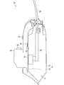
- FIG. 1 is an explanatory diagram showing an outline of a door in which a door wiring module is incorporated.
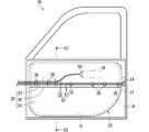
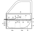
- FIG. 2 is a schematic side view showing a door in which the door wiring module according to the first embodiment is incorporated.
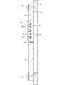
- FIG. 3 is a sectional view taken along line III-III in FIG.
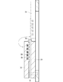
- FIG. 4 is an explanatory diagram showing a state in which the work opening is opened.
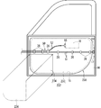
- FIG. 5 is an explanatory diagram showing a state in which the work opening is opened.
- FIG. 6 is a schematic side view showing a modified example of the working opening.
- FIG. 7 is a schematic side view showing another modification of the working opening.
- FIG. 8 is a schematic side view showing a modification of the position where the hinge portion is provided.
- FIG. 9 is a schematic side view showing a door in which the door wiring module according to the second embodiment is incorporated.
- FIG. 10 is a schematic side view showing a door surface member in the door wiring module according to the second embodiment.
- FIG. 11 is a schematic plan view showing a modified example of the locking portion.
- the wiring module of the present disclosure is as follows. (1) In a vehicle door, a door surface member that is incorporated between a door panel and a design trim and can close a work opening formed in the door panel, and the door surface member is attached to the door surface member. The wiring member, the door surface member is assembled in a first region of the door panel, and a second region different from the first region of the door panel. A second assembling portion, and in a state where the first assembling portion is assembled in the first area of the door panel, a portion of the working opening formed in the second area can be opened.
- a wiring module for a door wherein the second assembly portion is movably provided at a position outside the second region of the door panel. Since the wiring member is attached to the door surface member, the wiring member can be attached together when the door surface member is attached to the door panel.
- the portion of the work opening formed in the second area can be opened and the second assembly portion can be moved from the second area of the door panel. Since it is provided in the, the work using the work opening can be performed in this state. Since the second assembly portion is assembled to the second region portion after the work, it is possible to close the work opening formed in the door panel. Therefore, it is easy to work the work opening formed in the door panel.
- the planar member for a door is a planar member whose dimension in the thickness direction is smaller than the dimension in the surface direction.
- the door surface member further includes a hinge portion that connects the first assembly portion and the second assembly portion so as to be relatively bendable in a front-back direction. This is because when the first assembling portion is assembled to the door panel, the hinge portion allows the second assembling portion to bend with respect to the first assembling portion to open the working opening formed in the door panel. ..
- the planar member for door may further include a locking portion that detachably connects the first assembly portion and the second assembly portion. This is because the work opening formed in the door panel can be opened when the second assembling portion is not connected to the first assembling portion while the first assembling portion is attached to the door panel. Further, when the second assembling portion is assembled to the door panel, the second assembling portion can be connected to the first assembling portion by using the locking portion, which facilitates the assembling to the door panel.
- the wiring member may be fixed to only one of the first assembly portion and the second assembly portion.
- FIG. 1 is an explanatory diagram showing an outline of a door 10 in which a door wiring module 30 is incorporated.
- FIG. 2 is a schematic side view showing the door wiring module 30 according to the first embodiment.
- FIG. 3 is a sectional view taken along line III-III in FIG.
- the door 10 is formed in a flat shape as a whole, and is a portion that can be opened and closed so as to partition the inside and outside of the vehicle compartment.
- the door 10 is assumed to be a driver side door, a passenger side door, a rear seat door, or the like.
- the door 10 includes a door panel 12, a design trim 20, and a door wiring module 30.
- the door panel 12 includes an outer panel 13 and an inner panel 14.
- the outer panel 13 is a portion that is provided in a portion of the door 10 that faces the outside of the vehicle, and constitutes the exterior of the vehicle together with the body.
- the inner panel 14 is provided on the vehicle compartment side of the outer panel 13.
- a work opening 15 is formed in the inner panel 14.
- a door wiring module 30 is attached to the work opening 15 so as to close the work opening 15.
- the design trim 20 is provided on a portion of the door 10 that faces the inside of the vehicle, and constitutes the interior of the vehicle.
- a door handle 22, an operation unit 24 of an in-vehicle device, and the like are attached to the design trim 20, for example.
- the door wiring module 30 includes a door surface member 32 and a wiring member 50.
- the wiring member 50 is fixed to the door surface member 32. Therefore, when the door surface member 32 is incorporated into the door 10, the wiring member 50 is also incorporated into the door 10.
- the door surface member 32 is a surface member that is incorporated between the door panel 12 and the design trim 20 in the vehicle door 10.
- the term "planar member” as used herein refers to a member whose two-dimensionally spreads the thickness dimension smaller than the dimension in the plane direction (two directions orthogonal to the thickness direction), and is not necessarily flat in the front-back direction (thickness direction) It does not have to be, and unevenness may occur in the front and back directions.
- the door surface member 32 is a flat member that spreads to the same extent as or larger than the work opening 15.
- the door surface member 32 is provided so as to be capable of closing the work opening 15 formed in the door panel 12 when the door member 32 is assembled at a predetermined position of the vehicle door 10.
- the door surface member 32 can partition the inside and the outside of the vehicle.
- the door surface member 32 is assembled to the inner panel 14 by screwing, locking structure, or the like in a state where the door surface member 32 is located at a predetermined position that closes the working opening 15 of the inner panel 14. For example, as shown in FIG. 3, if a portion of the peripheral portion of the door surface member 32 that overlaps the inner panel 14 is screwed to the inner panel 14 by a screw B or the like, a gap between them is reduced as much as possible. Can be closed.
- a space S is formed between the outer panel 13 and the inner panel 14 and the door planar member 32 in a state where the door planar member 32 is assembled to the inner panel 14.
- the window 26 of the door 10 can be stored in this space S.
- a window 26 exposed to the rainwater environment is accommodated in the space S, and a slit-shaped opening through which the window 26 enters and exits is formed above the space S. Therefore, the space S is a space where water may enter.
- the space S is a space that may be connected to the external space, it is also a space in which wind noise or the like from the outside may enter. Therefore, the door surface member 32 is provided together with the inner panel 14 as a member that completely separates the vehicle compartment space and the external space.
- the door surface member 32 includes a plurality of mounting portions 33 and 34 which are mounted in different areas of the door panel 12.
- the assembling part 33 is the first assembling part 33 that is assembled in the first region of the door panel 12
- the assembling part 34 is the second set that is assembled in the second region different from the first region of the door panel 12. The description will be made assuming that it is the attachment unit 34.
- the first assembly portion 33 is assembled in the first area of the door panel 12
- the second assembly portion 34 is formed in the door panel 12 so that the portion of the work opening 15 formed in the second area can be opened. It is movably provided at a position outside the two areas.
- the work opening 15 When the work opening 15 is opened, the work opening 15 is opened so that the worker can perform necessary work in the space S in the door panel 12 after the first assembling portion 33 is assembled. It should be. All of the work openings 15 may be opened, or only a part of the work openings 15 may be opened. Preferably, the work opening 15 may be opened so that a worker can insert his/her hand in order to work in the space S. From this point of view, the work opening 15 can be regarded as an opening into which a worker can insert his/her hand in order to work in the space S.
- the work in the space S by the worker is, for example, a work of fitting a connector connected to an airbag sensor or the like in the space S, a work of attaching a grommet when the wiring member 50 is pulled out of the space S, or a space S. It is conceivable that this is an operation of gripping and taking out the components arranged inside.
- the first assembly portion 33 and the second assembly portion 34 preferably have rigidity that makes it difficult to bend them in the front-back direction.
- the edges and the like are difficult to bend, and the door member 12 is easily held in a spread shape, which facilitates the assembly.
- the first assembly portion 33 and the second assembly portion 34 are formed with higher rigidity than the wiring member 50.
- the door surface member 32 has a holding groove 35 formed on the main surface thereof, in which the wiring member 50 is accommodated.
- the holding groove 35 is formed according to the wiring form of the wiring member 50. Since the wiring member 50 is housed and held in the holding groove 35, the wiring member 50 is wired and held in the door surface member 32.
- the holding groove 35 is formed in the first assembly portion 33.
- the door surface member 32 further includes a hinge portion 38 that connects the first assembly portion 33 and the second assembly portion 34.
- the hinge part 38 is a part that connects the first assembly part 33 and the second assembly part 34 so as to be relatively bendable in the front-back direction.
- the hinge portion 38 is a thin-walled portion integrally formed with the first assembly portion 33 and the second assembly portion 34.
- the hinge portion 38 may have a configuration other than being formed thin.
- the hinge portion 38 is integrally formed with the shaft portion integrally formed with one of the first assembly portion 33 and the second assembly portion 34, and the other of the first assembly portion 33 and the second assembly portion 34. And a bearing portion that rotatably supports the shaft portion.
- the hinge portion 38 may have a component molded separately from the first assembly portion 33 and the second assembly portion 34.
- the hinge part 38 includes a shaft part and is attached to one of the first assembly part 33 and the second assembly part 34
- the hinge part 38 includes a bearing part and the first assembly part 33 and the second assembly part. It is conceivable that the configuration has a component attached to the other side of the portion 34.
- the hinge portion 38 is formed on each of the bearing portion formed on each of the first assembly portion 33 and the second assembly portion 34 and each of the first assembly portion 33 and the second assembly portion 34. It is conceivable that the configuration includes a component including a shaft portion attached to the bearing portion.
- the first assembling portion 33 and the second assembling portion 34 of the door surface member 32 are components molded by using, for example, resin or metal as a material.
- the door surface member 32 is made of resin or metal as a material and molded into a shape including the first assembly portion 33, the second assembly portion 34, and the thin hinge portion 38.
- the door surface member 32 may be formed by pouring a molten material into a mold, or may be formed by press-molding a plate material using the mold.
- the wiring member 50 is electrical wiring provided on the door 10 and connected to the electric components 17 and 18 provided on the door 10. A part of the wiring member 50 along the extending direction is wired and held by the door surface member 32.
- the term "wiring” as used herein means that wiring is performed in a form corresponding to the wiring state when the door 10 is assembled. Therefore, by assembling the door surface member 32 at a predetermined position with respect to the door 10, the wiring of the portion of the wiring member 50 that is wired and held by the door surface member 32 is completed to the door 10. To do.
- an intermediate portion of the wiring member 50 along the extending direction is wired and held by the door surface member 32.
- the wiring member 50 is fixed to only one of the first assembly portion 33 and the second assembly portion 34.
- the branch is formed in the wiring member 50 here.
- the branched portion of the wiring member 50 is wired and held by the door surface member 32. Therefore, the branched portion is maintained in the branched shape by the door surface member 32.
- the wiring member 50 includes a plurality of electric wires 51 and 52.
- the electric wires 51 and 52 a covered electric wire in which a coating is formed around a core wire made of a conductor can be used.
- the core wire may be a single core wire or a twisted wire.
- the plurality of electric wires 51 and 52 are arranged side by side on the door surface member 32.
- the plurality of electric wires 51 and 52 include a first electric wire 51 and a second electric wire 52.
- the three first electric wires 51 and the two second electric wires 52 are included, but the number of the first electric wires 51 and the second electric wires 52 is not limited to this. It is set appropriately according to the connected device and the like.
- the first electric wire 51 and the second electric wire 52 are gathered in a parallel state on one end side of each. One ends of the first electric wire 51 and the second electric wire 52 are connected to the wiring member 50 or the like on the vehicle body side.
- the electric components 17 and 18 provided on the door 10 are supplied with power from the battery mounted on the vehicle body, and exchange signals with the ECU or gateway mounted on the vehicle body.
- one ends of the first electric wire 51 and the second electric wire 52 extend outside the door 10.
- one ends of the first electric wire 51 and the second electric wire 52 are assembled so as to extend from the door 10 to the vehicle body and are connected to a wiring member or the like on the vehicle body side.
- one end of the first electric wire 51 and the second electric wire 52 may be housed in the door 10.
- the first electric wire 51 and the second electric wire 52 are branched at the middle portion in the extending direction.
- the branched portion is located on the door surface member 32.
- Connectors 54 and 55 are attached to the other ends of the first electric wire 51 and the second electric wire 52, respectively, and are connected to the electric components 17 and 18 via the connectors 54 and 55.
- the first electric wire 51 is connected to an electric component 17 incorporated in the rear portion of the door 10, for example, a door lock and unlock motor.
- the second electric wire 52 is connected to the electric component 18 incorporated in the middle portion of the door 10, for example, a motor for driving the window opening/closing jig 28 for opening/closing the window 26, or various switches.
- the first electric wire 51 and the second electric wire 52 are held in the holding groove 35.
- the holding grooves 35 are formed in parallel in a number corresponding to the plurality of electric wires 51 and 52.
- the plurality of electric wires 51 and 52 are individually held in the plurality of holding grooves 35.
- a plurality of electric wires 51 and 52 may be accommodated in one holding groove 35.
- the wiring member 50 is accommodated in the holding groove 35 formed in the door surface member 32 in a state where the wiring member 50 is prevented from coming off, so that the door surface member 32 and the wiring member 50 are fixed.
- a retaining portion 36 is formed on the upper portion of the holding groove 35 (portion opposite to the bottom portion of the holding groove 35). Since the wiring member 50 is held in the retaining groove 35 in a retaining shape by the retaining portion 36, the wiring member 50 can move in the retaining groove 35 along the longitudinal direction of the wiring member 50.
- the retaining portion 36 is formed by, for example, a protruding portion 37 protruding above the side wall portion of the holding groove 35 being crushed by a melting head 80.
- the structure for preventing the wiring member 50 from coming off from the holding groove 35 is not limited to this, and for example, a member different from the door surface member 32 presses the upper portion of the holding groove 35, or Various configurations such as a configuration in which an adhesive or the like is provided in the holding groove 35 can be adopted.
- the retaining portion 36 may close the entire holding groove 35 along the extending direction of the wiring member 50. Further, the retaining portion 36 may close a part of the holding groove 35 along the extending direction of the wiring member 50. In this case, it is preferable that a plurality of retaining portions 36 be provided at intervals along the extending direction of the wiring member 50.
- FIG. 4 is an explanatory diagram showing how the working opening 15 is opened.
- the working opening 15 is opened by moving the second assembling portion 34 to a position outside the second area in a state where the first assembling portion 33 is assembled in the first area.
- the working opening 15 is opened by the second assembly portion 34 being rotationally moved around the rotation axis of the hinge portion 38.
- the worker can work in the space S through the work opening 15.
- the work assembly 15 is closed by moving the second assembly part 34 to the second region. Be done.
- the second assembling portion 34 is bent with respect to the first assembling portion 33 by the hinge portion 38, so that the second assembling portion 34 moves to the second area and assumes the assembling posture.
- the wiring member 50 is fixed to only one of the first assembly portion 33 and the second assembly portion 34, the first of the first assembly portion 33 and the second assembly portion 34 When only one assembly portion 33 is assembled to the door panel 12 and the second assembly portion 34 is moved to a position outside the second region and the working opening 15 formed in the door panel 12 is opened, It is possible to prevent the wiring member 50 from being subjected to a load such as bending.
- the assembly order of the plurality of assembly parts 33 and 34 does not matter.
- the assembling part 33 is the first assembling part 33 and the assembling part 34 is the second assembling part 34, but it is conceivable that the assembling parts 33 are assembled in the reverse order. .. That is, the assembling unit 34 may be assembled first after the assembling unit 34 is assembled.
- the assembling part 34 is the first assembling part
- the assembling part 33 is the second assembling part.
- the part where the assembling part 34 is assembled is the first region
- the part where the assembling part 33 is assembled is the second region.
- the work opening 115 may be formed in such a manner that it is blocked by only the second mounting portion 34 of the first mounting portion 33 and the second mounting portion 34.
- an opening 16 different from the working opening 115 may be formed on the main surface of the inner panel 14.
- an opening for passing a part of the wiring member 50 from the outside of the space S to the inside of the space S can be considered.
- the different opening 16 may be closed by the door surface member 32 or may not be closed.
- the inner panel 14 is formed with a plurality of work openings 215a and 215b, as in the example shown in FIG.
- one second assembly part 34 may be formed in a size capable of closing the plurality of work openings 215a, 215b.
- a plurality of second assembling portions 34 may be provided, and the plurality of work openings 215a and 215b may be formed so that different second assembling portions 34 close each other.
- the rotation axis of the hinge portion 38 is provided so as to extend along the longitudinal direction of the door 10 (the front-back direction of the vehicle), but this is not an essential configuration.
- the rotation axis of the hinge portion 138 may be provided so as to extend along the height direction of the door 10.
- the plurality of assembling parts 133 and 134 in the door surface member 132 are arranged separately in the longitudinal direction of the door 10 (the front-rear direction of the vehicle). In the example shown in FIG. 8, which of the plurality of assembling parts 133 and 134 may be the first assembling part.
- the wiring member 50 since the wiring member 50 is attached to the door surface member 32, the wiring member 50 can be also attached when the door surface member 32 is attached to the door panel 12.
- the second assembly portion 34 is formed in the door panel 12 so that the portion of the work opening 15 formed in the second area can be opened. Since it is provided so as to be movable from two regions, it is possible to perform work using the work opening 15 in this state.
- the work opening 15 formed in the door panel 12 can be closed by assembling the second assembling portion 34 in the second region after the work, so that the work opening 15 formed in the door panel 12 can be closed. It will be easier to work on. From these, the work of assembling the wiring member 50 to the door 10 and the work of closing the work opening 15 formed in the door 10 can be facilitated.
- the work opening 15 formed in the door panel 12 is opened. It can be opened.
- the second assembling portion 34 is assembled to the door panel 12 after the work using the working opening 15, the second assembling portion 34 is bent by the hinge portion 38 with respect to the first assembling portion 33, so that the assembling is performed. It becomes easy to take a posture.
- the wiring member 50 When the wiring member 50 is fixed to only one of the first assembly portion 33 and the second assembly portion 34, the first assembly portion of the first assembly portion 33 and the second assembly portion 34.
- the attachment portion 33 When only the attachment portion 33 is assembled to the door panel 12 and the work opening 15 formed in the door panel 12 is opened, it is possible to prevent the wiring member 50 from being subjected to a load such as bending.
- FIG. 9 is a schematic side view showing the door wiring module 230 according to the second embodiment.
- FIG. 10 is a schematic side view showing the door planar member 232 in the door wiring module 230 according to the second embodiment.
- the same components as those described above are designated by the same reference numerals, and the description thereof will be omitted.
- the configuration of the door surface member 232 is different from the configuration of the door surface member 32.
- the door surface member 232 includes a first assembly portion 233 and a second assembly portion 234, and a locking portion 40 that detachably connects the first assembly portion 233 and the second assembly portion 234.
- the shapes of the first assembly portion 233 and the second assembly portion 234 are different from the shapes of the first assembly portion 33 and the second assembly portion 34. That is, the first assembling portion 33 and the second assembling portion 34 are formed in a shape that is connected at one edge, but the first assembling portion 233 and the second assembling portion 234 in this example are plural. It is formed in a shape that is connected by two (here, two) edges. Locking portions 40 are provided on the plurality of edges, respectively.
- the locking portion 40 includes a convex portion 41 and a concave portion 42 which are fitted to each other.
- the convex portion 41 projects in the surface direction with respect to the assembling portion.
- the recess 42 is formed so as to be recessed in the surface direction with respect to the assembly portion.
- the convex portion 41 has a portion that gradually widens from the base end portion in the protruding direction to the tip end portion.
- the recess 42 has a portion that gradually widens from the opening to the bottom opposite to the opening.
- the convex portion 41 is provided on at least one of the first assembly portion 233 and the second assembly portion 234, and the concave portion 42 is provided on at least the other.
- a plurality of (here, four) locking portions 40 are provided, and the projections 41 and the recesses 42 of the plurality (four here) of the locking portions 40 form the first assembly portion 233. It is distributed and arranged in both the second assembling section 234. Further, in the example shown in FIG. 11, a plurality of (here, two) locking portions 40 are provided at one edge, and a plurality of (two here) protrusions 41 in the plurality of (two here) locking portions 40 are provided at one edge.
- the recesses 42 are arranged in a distributed manner in both the first assembly part 233 and the second assembly part 234.
- the shape of the locking portion 40 is not limited to the above.
- any shape that can lock the first assembly portion 233 and the second assembly portion 234 can be adopted.
- a locking portion 140 including a locking piece 43 and a locking hole 44 that lock each other may be adopted.
- the locking piece 43 is formed so that it can be inserted into the locking hole 44 by elastically deforming the wings of the locking piece 43.
- the wing portion elastically returns after passing through the locking hole 44, so that the wing portion is hooked on the peripheral edge portion of the locking hole 44 and is locked with each other.
- the inserting direction of the locking piece 43 into the locking hole 44 is set in the thickness direction of the assembling parts 233, 234.
- the insertion direction of the locking piece 43 into the locking hole 44 may be set to the surface direction of the assembling parts 233 and 234.
- the opening 15 can be opened.
- the second assembling part 234 can be connected to the first assembling part 233 by using the locking part 40, so that the assembling to the door panel 12 is easy.
- one second assembly part is connected to one first assembly part, but a plurality of second assembly parts are connected to one first assembly part. It may be done. Further, the third assembling portion may be further connected to the second assembling portion. The third assembling portion is a portion formed so that a portion of the work opening different from the second assembling portion can be opened.
- first assembly portion and the second assembly portion are formed in a shape in which a plurality of edges are connected, one edge is connected by the locking portion 40 and the other edge is connected by the hinge portion 38. It may be configured.
- the wiring member 50 is arranged on the side of the door trim member 32 on the side of the design trim 20.
- the wiring member 50 may be disposed on the inner panel 14 side with respect to the door surface member 32, or may be disposed on both sides of the design trim 20 side and the inner panel 14 side.
Landscapes
- Engineering & Computer Science (AREA)
- Mechanical Engineering (AREA)
- Architecture (AREA)
- Civil Engineering (AREA)
- Structural Engineering (AREA)
- Installation Of Indoor Wiring (AREA)
- Lock And Its Accessories (AREA)
Abstract
ドアパネルへ配線部材を組付ける作業とドアパネルに形成された作業用開口を塞ぐ作業との容易化を図ることができる技術を提供することを目的とする。ドア用配線モジュールは、車両のドアに組込まれてドアパネルに形成された作業用開口を塞ぐことが可能なドア用面状部材と、前記ドア用面状部材に取付けられた配線部材と、を備え、前記ドア用面状部材は、前記ドアパネルにおける第1領域に組付けられる第1組付部と、前記ドアパネルにおける前記第1領域とは異なる第2領域に組付けられる第2組付部とを含み、前記第1組付部が前記ドアパネルにおける前記第1領域に組付けられた状態において、前記作業用開口のうち前記第2領域に形成された部分を開放可能に前記第2組付部が前記ドアパネルにおける前記第2領域から外れた位置に移動可能に設けられている。
Description
本開示は、ドア用配線モジュールに関する。
特許文献1は、作業窓と呼ばれる作業用の開口(サービスホールなどとも呼ばれる)があけられたドア本体にワイヤハーネスを組付ける技術を開示している。特許文献1では、ドア本体にワイヤハーネスを組付けた後、防水シートによって作業窓を塞いでいる。これにより、ドア本体にワイヤハーネスを組付ける際、作業窓を用いた作業を行うことができる。作業窓を用いた作業として、特許文献1には、ワイヤハーネスの端部に設けられたコネクタを嵌合する作業が記載されている。作業窓を用いた作業として、このほか、ワイヤハーネスのうち車体側で延びる部分に取付けられたグロメットをドア本体に形成された孔に挿通させる作業なども行われることがある。
ドア本体へワイヤハーネスを組付ける作業と作業窓を塞ぐ作業との容易化が望まれている。
そこで、ドアパネルへ配線部材を組付ける作業とドアパネルに形成された作業用開口を塞ぐ作業との容易化を図ることができる技術を提供することを目的とする。
本開示のドア用配線モジュールは、車両のドアにおいて、ドアパネルと意匠トリムとの間に組込まれて前記ドアパネルに形成された作業用開口を塞ぐことが可能なドア用面状部材と、前記ドア用面状部材に取付けられた配線部材と、を備え、前記ドア用面状部材は、前記ドアパネルにおける第1領域に組付けられる第1組付部と、前記ドアパネルにおける前記第1領域とは異なる第2領域に組付けられる第2組付部とを含み、前記第1組付部が前記ドアパネルにおける前記第1領域に組付けられた状態において、前記作業用開口のうち前記第2領域に形成された部分を開放可能に前記第2組付部が前記ドアパネルにおける前記第2領域から外れた位置に移動可能に設けられている、ドア用配線モジュールである。
本開示によれば、ドアパネルへ配線部材を組付ける作業とドアパネルに形成された作業用開口を塞ぐ作業との容易化を図ることができる。
[本開示の実施形態の説明]
最初に本開示の実施態様を列記して説明する。
本開示の配線モジュールは、次の通りである。
(1)車両のドアにおいて、ドアパネルと意匠トリムとの間に組込まれて前記ドアパネルに形成された作業用開口を塞ぐことが可能なドア用面状部材と、前記ドア用面状部材に取付けられた配線部材と、を備え、前記ドア用面状部材は、前記ドアパネルにおける第1領域に組付けられる第1組付部と、前記ドアパネルにおける前記第1領域とは異なる第2領域に組付けられる第2組付部とを含み、前記第1組付部が前記ドアパネルにおける前記第1領域に組付けられた状態において、前記作業用開口のうち前記第2領域に形成された部分を開放可能に前記第2組付部が前記ドアパネルにおける前記第2領域から外れた位置に移動可能に設けられている、ドア用配線モジュールである。
配線部材がドア用面状部材に取付けられているため、ドアパネルへのドア用面状部材の組付け時に配線部材も併せて組付けることができる。第1組付部がドアパネルにおける第1領域に組付けられた状態において、作業用開口のうち第2領域に形成された部分を開放可能に第2組付部がドアパネルにおける第2領域から移動可能に設けられているため、この状態で作業用開口を用いた作業を行うことができる。そして、作業後に第2組付部が第2領域部に組付けられることによってドアパネルに形成された作業用開口を塞ぐことが可能であるため、ドアパネルに形成された作業用開口を塞ぐ作業が容易となる。これらより、ドアへ配線部材を組付ける作業とドアに形成された作業用開口を塞ぐ作業との容易化を図ることができる。
ここでドア用面状部材とは厚み方向の寸法が面方向の寸法よりも小さい面状の部材である。
(2)前記ドア用面状部材は前記第1組付部及び前記第2組付部を表裏方向に相対的に曲げ可能に連結するヒンジ部をさらに含むことが好ましい。第1組付部がドアパネルに組付けられた状態でヒンジ部によって第2組付部が第1組付部に対して曲がることによってドアパネルに形成された作業用開口を開放可能であるからである。さらに作業用開口を用いた作業後に第2組付部をドアパネルへ組付けるときに、ヒンジ部によって第2組付部が第1組付部に対して曲がることで、組付姿勢となることが容易となる。
(3)前記ドア用面状部材は前記第1組付部及び前記第2組付部を着脱可能に連結する係止部をさらに含むと良い。第1組付部がドアパネルに組付けられた状態で、第2組付部が第1組付部と連結されていないときにドアパネルに形成された作業用開口を開放可能であるからである。さらに第2組付部をドアパネルへ組付ける際、係止部を用いて第2組付部を第1組付部に連結させることができることによって、ドアパネルへの組付けが容易となる。第2組付部をドアパネルに直接的に固定する箇所を少なくできる。
(4)前記配線部材は前記第1組付部と前記第2組付部とのうちいずれか一方のみに固定されていると良い。第1組付部と第2組付部とのうち第1組付部のみがドアパネルに組付けられてドアパネルに形成された作業用開口が開いた状態となる際、配線部材に曲げなどによる負荷がかかることが抑制されるからである。
最初に本開示の実施態様を列記して説明する。
本開示の配線モジュールは、次の通りである。
(1)車両のドアにおいて、ドアパネルと意匠トリムとの間に組込まれて前記ドアパネルに形成された作業用開口を塞ぐことが可能なドア用面状部材と、前記ドア用面状部材に取付けられた配線部材と、を備え、前記ドア用面状部材は、前記ドアパネルにおける第1領域に組付けられる第1組付部と、前記ドアパネルにおける前記第1領域とは異なる第2領域に組付けられる第2組付部とを含み、前記第1組付部が前記ドアパネルにおける前記第1領域に組付けられた状態において、前記作業用開口のうち前記第2領域に形成された部分を開放可能に前記第2組付部が前記ドアパネルにおける前記第2領域から外れた位置に移動可能に設けられている、ドア用配線モジュールである。
配線部材がドア用面状部材に取付けられているため、ドアパネルへのドア用面状部材の組付け時に配線部材も併せて組付けることができる。第1組付部がドアパネルにおける第1領域に組付けられた状態において、作業用開口のうち第2領域に形成された部分を開放可能に第2組付部がドアパネルにおける第2領域から移動可能に設けられているため、この状態で作業用開口を用いた作業を行うことができる。そして、作業後に第2組付部が第2領域部に組付けられることによってドアパネルに形成された作業用開口を塞ぐことが可能であるため、ドアパネルに形成された作業用開口を塞ぐ作業が容易となる。これらより、ドアへ配線部材を組付ける作業とドアに形成された作業用開口を塞ぐ作業との容易化を図ることができる。
ここでドア用面状部材とは厚み方向の寸法が面方向の寸法よりも小さい面状の部材である。
(2)前記ドア用面状部材は前記第1組付部及び前記第2組付部を表裏方向に相対的に曲げ可能に連結するヒンジ部をさらに含むことが好ましい。第1組付部がドアパネルに組付けられた状態でヒンジ部によって第2組付部が第1組付部に対して曲がることによってドアパネルに形成された作業用開口を開放可能であるからである。さらに作業用開口を用いた作業後に第2組付部をドアパネルへ組付けるときに、ヒンジ部によって第2組付部が第1組付部に対して曲がることで、組付姿勢となることが容易となる。
(3)前記ドア用面状部材は前記第1組付部及び前記第2組付部を着脱可能に連結する係止部をさらに含むと良い。第1組付部がドアパネルに組付けられた状態で、第2組付部が第1組付部と連結されていないときにドアパネルに形成された作業用開口を開放可能であるからである。さらに第2組付部をドアパネルへ組付ける際、係止部を用いて第2組付部を第1組付部に連結させることができることによって、ドアパネルへの組付けが容易となる。第2組付部をドアパネルに直接的に固定する箇所を少なくできる。
(4)前記配線部材は前記第1組付部と前記第2組付部とのうちいずれか一方のみに固定されていると良い。第1組付部と第2組付部とのうち第1組付部のみがドアパネルに組付けられてドアパネルに形成された作業用開口が開いた状態となる際、配線部材に曲げなどによる負荷がかかることが抑制されるからである。
[本開示の実施形態の詳細]
本開示のドア用配線モジュールの具体例を、以下に図面を参照しつつ説明する。なお、本発明はこれらの例示に限定されるものではなく、請求の範囲によって示され、請求の範囲と均等の意味および範囲内でのすべての変更が含まれることが意図される。
本開示のドア用配線モジュールの具体例を、以下に図面を参照しつつ説明する。なお、本発明はこれらの例示に限定されるものではなく、請求の範囲によって示され、請求の範囲と均等の意味および範囲内でのすべての変更が含まれることが意図される。
[実施形態1]
以下、実施形態1に係るドア用配線モジュールについて説明する。図1はドア用配線モジュール30が組み込まれたドア10の概要を示す説明図である。図2は実施形態1にかかるドア用配線モジュール30を示す概略側面図である。図3は図2のIII-III線に沿って切断した断面図である。
以下、実施形態1に係るドア用配線モジュールについて説明する。図1はドア用配線モジュール30が組み込まれたドア10の概要を示す説明図である。図2は実施形態1にかかるドア用配線モジュール30を示す概略側面図である。図3は図2のIII-III線に沿って切断した断面図である。
ドア10は、全体として偏平な形状に形成されており、車両において車室内と車室外とを仕切るように開閉可能に設けられる部分である。ドア10は、運転席側ドア、助手席側ドア、後部座席用ドアである場合等が想定される。ドア10は、ドアパネル12と、意匠トリム20と、ドア用配線モジュール30とを備える。
ドアパネル12は、アウターパネル13と、インナーパネル14とを備える。アウターパネル13は、ドア10のうち車両外側に面する部分に設けられ、ボディと共に車両の外観を構成する部分である。インナーパネル14は、アウターパネル13の車室側に設けられている。インナーパネル14には、作業用開口15が形成されている。この作業用開口15に、当該作業用開口15を閉じるようにドア用配線モジュール30が取付けられる。
意匠トリム20は、ドア10のうち車室内側に面する部分に設けられ、車両の内観を構成する部分である。意匠トリム20には例えば、ドアハンドル22、車載機器の操作部24等が取付けられる。
ドア用配線モジュール30は、ドア用面状部材32と、配線部材50と、を備える。配線部材50はドア用面状部材32に固定されている。このため、ドア用面状部材32がドア10に組込まれることによって、配線部材50も併せてドア10に組み込まれる。
ドア用面状部材32は、車両のドア10においてドアパネル12と意匠トリム20との間に組込まれる面状の部材である。なお、ここでいう面状の部材とは、厚み寸法が、面方向(厚み方向に直交する2方向)の寸法よりも小さい2次元的に広がる部材を言い、必ずしも表裏方向(厚み方向)に平坦である必要はなく、表裏方向に凹凸が生じていてもよい。
ドア用面状部材32は、作業用開口15と同じ程度又は作業用開口15よりも大きく広がる偏平な部材である。ドア用面状部材32は、車両のドア10の所定位置に組付けられた状態において、ドアパネル12に形成された作業用開口15を塞ぐことが可能に設けられている。これにより、ドア用面状部材32は、車両の内側と外側とを仕切ることができる。ドア用面状部材32がインナーパネル14の作業用開口15を塞ぐ所定位置に位置する状態で、ネジ止、係止構造等によってインナーパネル14に組付けられる。例えば、図3に示すようにドア用面状部材32の周縁部のうちインナーパネル14に重なる部分がネジB等によってインナーパネル14にネジ止されれば、それらの間の隙間を可及的に塞ぐことができる。
ドア用面状部材32がインナーパネル14に組付けられた状態で、アウターパネル13と、インナーパネル14及びドア用面状部材32との間に空間Sが形成される。この空間Sに、ドア10のウインドウ26を収納することができる。当該空間Sには、雨水環境に曝されるウインドウ26が収容され、また、当該空間Sの上方には、ウインドウ26が出入りするスリット状の開口が形成されている。このため、当該空間Sは、水が侵入する可能性がある空間である。また、当該空間Sは、外部空間と繋がる可能性のある空間であるため、外部からの風切り音等が侵入する恐れがある空間でもある。そこで、ドア用面状部材32は、インナーパネル14と共に車室空間と外部空間とをより完全に仕切る部材として設けられている。
ドア用面状部材32は、ドアパネル12における相互に異なる領域に組付けられる複数の組付部33、34を含む。ここでは組付部33がドアパネル12における第1領域に組付けられる第1組付部33であり、組付部34がドアパネル12における第1領域とは異なる第2領域に組付けられる第2組付部34であるものとして説明する。第1組付部33がドアパネル12における第1領域に組付けられた状態において、作業用開口15のうち第2領域に形成された部分を開放可能に第2組付部34がドアパネル12における第2領域から外れた位置に移動可能に設けられている。
作業用開口15が開放されるにあたって、作業用開口15は、第1組付部33が組付けられた後に、作業者がドアパネル12内の空間Sにおいて必要な作業が可能となるように開放されていればよい。作業用開口15の全部が開放されてもよいし、作業用開口15の一部のみが開放されてもよい。好ましくは、作業用開口15は、作業者が空間S内での作業を行うために手を挿入可能に開放されているとよい。この観点で見ると、作業用開口15は、作業者が空間S内での作業を行うために手を挿入可能な開口ととらえることができる。作業者による空間S内での作業は、例えば、空間S内においてエアバッグセンサなどに接続するコネクタの嵌合作業、配線部材50を空間Sの外に引き出す際のグロメットの取付作業、又は空間S内に配置される部品を把持して取り出す作業などであることが考えられる。
第1組付部33及び第2組付部34は、表裏方向に曲げ困難な剛性を有しているとよい。これにより、ドア用面状部材32がドアパネル12に組付けられるときに、縁部などが曲がりにくく、広がった形状に保たれやすいことによって、組付けが容易となる。例えば、第1組付部33及び第2組付部34は、配線部材50よりも高剛性に形成されている。
ドア用面状部材32には、その主面上に配線部材50が収容される保持溝35が形成されている。保持溝35は、配線部材50の配線形態に応じて形成されている。配線部材50が保持溝35に収容保持されることによって、配線部材50がドア用面状部材32に配線されて保持された状態となる。ここでは第1組付部33に保持溝35が形成されている。
ここでは第1組付部33及び第2組付部34が連結されるものとして説明する。特にここでは、第1組付部33及び第2組付部34がヒンジ部38によって連結されるものとして説明する。従ってドア用面状部材32は、第1組付部33及び第2組付部34を連結するヒンジ部38をさらに含む。
ヒンジ部38は、第1組付部33及び第2組付部34を表裏方向に相対的に曲げ可能に連結する部分である。図3に示す例では、ヒンジ部38は、薄肉状に形成されて、第1組付部33及び第2組付部34と一体成形された部分である。
もちろんヒンジ部38は、薄肉状に形成される以外の構成であってもよい。例えば、ヒンジ部38は、第1組付部33及び第2組付部34の一方と一体成形される軸部と、第1組付部33及び第2組付部34の他方と一体成形されて軸部を回転可能に支持する軸受部とを有するように構成されていてもよい。またヒンジ部38は、第1組付部33及び第2組付部34と別に成形された部品を有していてもよい。この場合、例えば、ヒンジ部38は、軸部を含み第1組付部33及び第2組付部34の一方に取付けられる部品と、軸受部を含み第1組付部33及び第2組付部34の他方に取付けられる部品とを有する構成であることが考えられる。また例えば、ヒンジ部38は、第1組付部33及び第2組付部34のそれぞれに形成された軸受部と、第1組付部33及び第2組付部34のそれぞれに形成された軸受部に取付けられる軸部を含む部品とを有する構成であることが考えられる。
ドア用面状部材32における第1組付部33及び第2組付部34は、例えば樹脂又は金属を材料として金型成型された部品である。ここではドア用面状部材32が、樹脂又は金属を材料として第1組付部33、第2組付部34及び薄肉状のヒンジ部38を含む形状に金型成型されている。ドア用面状部材32は、金型内に溶融材料が流し込まれて成型されたものでもよいし、板材が金型を用いたプレス成型されて成型されたものであってもよい。
配線部材50は、ドア10に設けられ、当該ドア10に設けられた電気部品17、18に接続される電気的な配線である。配線部材50のうち延在方向に沿った一部が、ドア用面状部材32に配線されて保持されている。ここでいう配線とは、ドア10への組付け時の配線状態に応じた形態に配線されていることをいう。従って、ドア10に対して、ドア用面状部材32を所定位置に組付けることによって、配線部材50のうちドア用面状部材32に配線されて保持された部分のドア10への配線が完了する。
ここでは配線部材50のうち延在方向に沿った中間部がドア用面状部材32に配線されて保持されている。配線部材50は第1組付部33と第2組付部34とのうちいずれか一方のみに固定されている。
ここでは配線部材50には、分岐が形成されている。配線部材50におけるこの分岐部分は、ドア用面状部材32に配線されて保持されている。従って、分岐部分は、ドア用面状部材32によって、その分岐形状が維持されている。
より具体的には、配線部材50は、複数の電線51、52を含む。電線51、52としては、導体で構成された芯線の周囲に被覆が形成された被覆電線を用いることができる。芯線は、単芯線であってもよいし、撚り合せ線であってもよい。複数の電線51、52は、ドア用面状部材32上に並んで配線されている。
ここでは、複数の電線51、52は、第1電線51及び第2電線52を含む。なお図2に示す例では、3本の第1電線51と、2本の第2電線52とで構成されているが、第1電線51及び第2電線52の数は、これに限られず、接続される機器等に応じて適宜設定される。第1電線51及び第2電線52は、それぞれの一端側では並列状態に集合されている。第1電線51及び第2電線52の一端部は、車両本体側の配線部材50などに接続される。これにより、ドア10に設けられた電気部品17、18が、車両本体に搭載されるバッテリから電源供給を受けたり、車両本体に搭載されるECU又はゲートウェイなどと信号授受がなされたりする。なお図2に示す例では、第1電線51及び第2電線52の一端部がドア10外に延びている。第1電線51及び第2電線52の一端部は、例えば、ドア10から車体に渡るように組付けられて車両本体側の配線部材などに接続される。もちろん、第1電線51及び第2電線52の一端部がドア10内に収まっていてもよい。
第1電線51及び第2電線52は、延在方向中間部で分岐している。この分岐部分がドア用面状部材32に位置している。第1電線51及び第2電線52のそれぞれの他端部には、コネクタ54、55が取付けられており、当該コネクタ54、55を介して電気部品17、18に接続される。第1電線51は、ドア10の後部に組込まれる電気部品17、例えば、ドアロック及びアンロック用モータに接続される。また例えば、第2電線52は、ドア10の中間部に組込まれる電気部品18、例えば、ウインドウ26を開閉するための窓開閉治具28を駆動するモータ、又は各種スイッチ等に接続される。
第1電線51及び第2電線52は、保持溝35内に保持されている。ここでは、保持溝35は、複数の電線51、52に応じた数、並列状態で形成されている。複数の電線51、52は、複数の保持溝35内に個別に保持されている。もっとも、1つの保持溝35に複数本の電線51、52が収められていてもよい。
図3に示す例では、ドア用面状部材32に形成された保持溝35に配線部材50が抜け止めされた状態で収められることによって、ドア用面状部材32と、配線部材50とが固定されている。例えば、図3に示す例では、配線部材50の抜け止めを図る構成として、保持溝35の上部(保持溝35の底部と反対側の部分)に抜止部36が形成されている。配線部材50は保持溝35に収容された状態で抜止部36によって抜け止め状に保持されているため、保持溝35内を配線部材50の長手方向に沿って移動可能である。
抜止部36は、例えば、保持溝35の側壁部分の上方に突出する突出部分37が溶解用ヘッド80によって潰されて形成される。もちろん、保持溝35からの配線部材50の抜け止めを図る構成は、これに限られるものではなく、例えば、ドア用面状部材32とは別の部材が保持溝35の上部を押さえる構成、又は保持溝35内に接着剤などが設けられる構成など種々の構成を採用することができる。抜止部36は、配線部材50の延在方向に沿って保持溝35の全部を塞いでもよい。また抜止部36は、配線部材50の延在方向に沿って保持溝35の一部を塞いでもよい。この場合、抜止部36は、配線部材50の延在方向に沿って間隔をあけて複数設けられているとよい。
図4は作業用開口15が開放される様子を示す説明図である。図4に示すように、第1組付部33が第1領域に組付けられた状態で第2組付部34が第2領域から外れた位置に移動することによって、作業用開口15が開放される。ここでは、第2組付部34がヒンジ部38の回転軸回りに回転移動することによって、作業用開口15が開放される。この状態で作業者は、作業用開口15を通じて空間S内での作業を行うことができる。作業用開口15を用いた作業が終了した後に第2組付部34をドアパネル12へ組付けるときに、第2組付部34が第2領域に移動することによって、作業用開口15が塞がれる。ここではヒンジ部38によって第2組付部34が第1組付部33に対して曲がることによって、第2組付部34が第2領域に移動して組付姿勢となる。
このとき配線部材50が第1組付部33と第2組付部34とのうちいずれか一方のみに固定されていると、第1組付部33と第2組付部34とのうち第1組付部33のみがドアパネル12に組付けられると共に第2組付部34が第2領域から外れた位置に移動してドアパネル12に形成された作業用開口15が開いた状態となる際、配線部材50に曲げなどによる負荷がかかることが抑制される。
なおドア用配線モジュール30において、複数の組付部33、34の組付順が問われないことも考えられる。具体的には上記例では、組付部33が第1組付部33であり、組付部34が第2組付部34とされていたが、逆の順番で組付けられることも考えられる。すなわち、組付部34が先に組付けられた後に、組付部33が組付けられてもよい。この場合、組付部34が第1組付部であり、組付部33が第2組付部とされる。組付部34が組付けられる部分が第1領域であり、組付部33が組付けられる部分が第2領域である。そして図5に示すように、組付部34が組付けられた状態で、組付部33がヒンジ部38の回転軸回りに回転移動することによって、作業用開口15が開放される。
これまで示した例では、インナーパネル14に作業用開口15が1つのみ形成されて、この1つの作業用開口15を第1組付部33及び第2組付部34によって塞いでいるものであったが、インナーパネル14に形成される作業用開口15の数、形状等はこの限りではない。
例えば図6に示す例のように、作業用開口115が第1組付部33及び第2組付部34のうち第2組付部34のみによって塞がれる態様で形成されていてもよい。このように作業用開口115がインナーパネル14と比べて小さく形成されている場合、インナーパネル14における主面には作業用開口115とは別の開口16が形成されていることもあり得る。別の開口16としては、例えば配線部材50の一部を空間Sの外部から空間Sの内部に通すための開口などが考えられる。この別の開口16は、ドア用面状部材32によって塞がれていてもよいし、塞がれていなくてもよい。
また例えば図7に示す例のように、インナーパネル14に複数の作業用開口215a、215bが形成されていることも考えられる。この場合、例えば、1つの第2組付部34が複数の作業用開口215a、215bを塞ぐことができる大きさに形成されていてもよい。また例えば、第2組付部34が複数設けられ、複数の作業用開口215a、215bをそれぞれ別の第2組付部34が塞ぐように形成されていてもよい。
これまで示した例では、ヒンジ部38における回転軸がドア10の長手方向(車両の前後方向)に沿って延びるように設けられていたが、このことは必須の構成ではない。例えば、図8に示す例におけるドア用配線モジュール130のように、ヒンジ部138における回転軸がドア10の高さ方向に沿って延びるように設けられていてもよい。この場合、ドア用面状部材132における複数の組付部133、134は、ドア10の長手方向(車両の前後方向)に分かれて配置される。図8に示す例において複数の組付部133、134のうちどちらが第1組付部とされてもよい。
本開示によると、配線部材50がドア用面状部材32に取付けられているため、ドアパネル12へのドア用面状部材32の組付け時に配線部材50も併せて組付けることができる。第1組付部33がドアパネル12における第1領域に組付けられた状態において、作業用開口15のうち第2領域に形成された部分を開放可能に第2組付部34がドアパネル12における第2領域から移動可能に設けられているため、この状態で作業用開口15を用いた作業を行うことができる。そして、作業後に第2組付部34が第2領域部に組付けられることによってドアパネル12に形成された作業用開口15を塞ぐことが可能であるため、ドアパネル12に形成された作業用開口15を塞ぐ作業が容易となる。これらより、ドア10へ配線部材50を組付ける作業とドア10に形成された作業用開口15を塞ぐ作業との容易化を図ることができる。
第1組付部33がドアパネル12に組付けられた状態でヒンジ部38によって第2組付部34が第1組付部33に対して曲がることによってドアパネル12に形成された作業用開口15を開放可能である。作業用開口15を用いた作業後に第2組付部34をドアパネル12へ組付けるときに、ヒンジ部38によって第2組付部34が第1組付部33に対して曲がることで、組付姿勢となることが容易となる。
配線部材50が第1組付部33と第2組付部34とのうちいずれか一方のみに固定されていると、第1組付部33と第2組付部34とのうち第1組付部33のみがドアパネル12に組付けられてドアパネル12に形成された作業用開口15が開いた状態となる際、配線部材50に曲げなどによる負荷がかかることが抑制される。
[実施形態2]
実施形態2に係るドア用配線モジュールについて説明する。図9は実施形態2にかかるドア用配線モジュール230を示す概略側面図である。図10は実施形態2にかかるドア用配線モジュール230におけるドア用面状部材232を示す概略側面図である。なお、本実施の形態の説明において、これまで説明したものと同様構成要素については同一符号を付してその説明を省略する。
実施形態2に係るドア用配線モジュールについて説明する。図9は実施形態2にかかるドア用配線モジュール230を示す概略側面図である。図10は実施形態2にかかるドア用配線モジュール230におけるドア用面状部材232を示す概略側面図である。なお、本実施の形態の説明において、これまで説明したものと同様構成要素については同一符号を付してその説明を省略する。
本例ではドア用面状部材232の構成が上記ドア用面状部材32の構成とは異なる。ドア用面状部材232は、第1組付部233及び第2組付部234と、第1組付部233及び第2組付部234を着脱可能に連結する係止部40とを含む。また本例では、第1組付部233及び第2組付部234の形状が上記第1組付部33及び第2組付部34の形状とは異なっている。すなわち上記第1組付部33及び第2組付部34は、一の縁で連結される形状に形成されていたが、本例における第1組付部233及び第2組付部234は複数(ここでは2つ)の縁で連結される形状に形成されている。係止部40が複数の縁にそれぞれ設けられている。
係止部40は、相互に嵌り合う凸部41と凹部42とを含む。凸部41は、組付部に対して面方向に突出する。凹部42は、組付部に対して面方向に凹むように形成されている。凸部41は、突出方向基端部から先端部にかけて徐々に幅広となる部分を有している。凹部42は、開口部から開口部と反対側の底部にかけて徐々に幅広となる部分を有している。これらより、凸部41と凹部42とが相互に嵌り合った状態で、組付部の面方向に抜けにくくなっている。
第1組付部233と第2組付部234とのうち少なくとも一方に凸部41が設けられ、少なくとも他方に凹部42が設けられる。図11に示すでは複数(ここでは4つ)の係止部40が設けられて、複数(ここでは4つ)の係止部40における凸部41と凹部42とが第1組付部233と第2組付部234との両方に分散して配置されている。また図11に示す例では、一の縁に複数(ここでは2つ)の係止部40が設けられて、一の縁において複数(ここでは2つ)の係止部40における凸部41と凹部42とが第1組付部233と第2組付部234との両方に分散して配置されている。
もっとも係止部40の形状は上記したものに限られない。係止部40として第1組付部233及び第2組付部234を係止可能な任意の形状を採用可能である。例えば、図11に示すように、相互に係止する係止片43と係止孔44とを含む係止部140が採用されていてもよい。係止片43は、係止片43における羽部が弾性変形することによって係止孔44に挿入可能に形成されている。そして羽部が係止孔44を通過後に弾性復帰することによって係止孔44の周縁部に引っかかった状態となり、相互に係止した状態となる。図11に示す例では、係止孔44への係止片43の挿入方向が、組付部233、234の厚み方向に設定されている。もちろん、係止孔44への係止片43の挿入方向が、組付部233、234の面方向などに設定されていてもよい。
本開示によると、第1組付部233がドアパネル12に組付けられた状態で、第2組付部234が第1組付部233と連結されていないときにドアパネル12に形成された作業用開口15を開放可能である。第2組付部234をドアパネル12へ組付ける際、係止部40を用いて第2組付部234を第1組付部233に連結させることができることによって、ドアパネル12への組付けが容易となる。第2組付部234をドアパネル12に直接的に固定する箇所を少なくできる。
[付記]
上記例では、一の第1組付部に対して一の第2組付部が連結されるものであったが、一の第1組付部に対して複数の第2組付部が連結されるものであってもよい。また第2組付部に対してさらに第3組付部が連結されるものであってもよい。第3組付部は、作業用開口のうち第2組付部とは異なる部分を開放可能に形成される部分である。
上記例では、一の第1組付部に対して一の第2組付部が連結されるものであったが、一の第1組付部に対して複数の第2組付部が連結されるものであってもよい。また第2組付部に対してさらに第3組付部が連結されるものであってもよい。第3組付部は、作業用開口のうち第2組付部とは異なる部分を開放可能に形成される部分である。
第1組付部及び第2組付部が複数の縁で連結される形状に形成されている場合、一の縁において係止部40によって連結され、他の縁がヒンジ部38によって連結される構成であってもよい。
上記例では配線部材50は、ドア用面状部材32に対して意匠トリム20側に配設されている。もっとも配線部材50は、ドア用面状部材32に対してインナーパネル14側に配設されていてもよく、意匠トリム20側とインナーパネル14側との両側に配設されていてもよい。
なお、上記各実施形態及び各変形例で説明した各構成は、相互に矛盾しない限り適宜組合わせることができる。
10 ドア
12 ドアパネル
13 アウターパネル
14 インナーパネル
15、115、215a、215b 作業用開口
16 開口
17、18 電気部品
20 意匠トリム
22 ドアハンドル
24 操作部
26 ウインドウ
28 窓開閉治具
30、130、230 ドア用配線モジュール
32、132、232 ドア用面状部材
33、34、133、134、233、234 組付部
35 保持溝
36 抜止部
37 突出部分
38、138 ヒンジ部
40、140 係止部
41 凸部
42 凹部
43 係止片
44 係止孔
50 配線部材
51、52 電線
54、55 コネクタ
80 溶解用ヘッド
B ネジ
S 空間
12 ドアパネル
13 アウターパネル
14 インナーパネル
15、115、215a、215b 作業用開口
16 開口
17、18 電気部品
20 意匠トリム
22 ドアハンドル
24 操作部
26 ウインドウ
28 窓開閉治具
30、130、230 ドア用配線モジュール
32、132、232 ドア用面状部材
33、34、133、134、233、234 組付部
35 保持溝
36 抜止部
37 突出部分
38、138 ヒンジ部
40、140 係止部
41 凸部
42 凹部
43 係止片
44 係止孔
50 配線部材
51、52 電線
54、55 コネクタ
80 溶解用ヘッド
B ネジ
S 空間
Claims (4)
- 車両のドアにおいて、ドアパネルと意匠トリムとの間に組込まれて前記ドアパネルに形成された作業用開口を塞ぐことが可能なドア用面状部材と、
前記ドア用面状部材に取付けられた配線部材と、
を備え、
前記ドア用面状部材は、前記ドアパネルにおける第1領域に組付けられる第1組付部と、前記ドアパネルにおける前記第1領域とは異なる第2領域に組付けられる第2組付部とを含み、前記第1組付部が前記ドアパネルにおける前記第1領域に組付けられた状態において、前記作業用開口のうち前記第2領域に形成された部分を開放可能に前記第2組付部が前記ドアパネルにおける前記第2領域から外れた位置に移動可能に設けられている、ドア用配線モジュール。 - 請求項1に記載のドア用配線モジュールであって、
前記ドア用面状部材は、前記第1組付部及び前記第2組付部を表裏方向に相対的に曲げ可能に連結するヒンジ部をさらに含む、ドア用配線モジュール。 - 請求項1に記載のドア用配線モジュールであって、
前記ドア用面状部材は、前記第1組付部及び前記第2組付部を着脱可能に連結する係止部をさらに含む、ドア用配線モジュール。 - 請求項1から請求項3のいずれか1項に記載のドア用配線モジュールであって、
前記配線部材は前記第1組付部と前記第2組付部とのうちいずれか一方のみに固定されている、ドア用配線モジュール。
Priority Applications (2)
| Application Number | Priority Date | Filing Date | Title |
|---|---|---|---|
| CN202080012729.4A CN113439042A (zh) | 2019-02-20 | 2020-01-31 | 车门用配线模块 |
| US17/429,232 US20220009324A1 (en) | 2019-02-20 | 2020-01-31 | Attachment structure of door wiring module |
Applications Claiming Priority (2)
| Application Number | Priority Date | Filing Date | Title |
|---|---|---|---|
| JP2019-028364 | 2019-02-20 | ||
| JP2019028364A JP7147620B2 (ja) | 2019-02-20 | 2019-02-20 | ドア用配線モジュール |
Publications (1)
| Publication Number | Publication Date |
|---|---|
| WO2020170756A1 true WO2020170756A1 (ja) | 2020-08-27 |
Family
ID=72143792
Family Applications (1)
| Application Number | Title | Priority Date | Filing Date |
|---|---|---|---|
| PCT/JP2020/003583 Ceased WO2020170756A1 (ja) | 2019-02-20 | 2020-01-31 | ドア用配線モジュール |
Country Status (4)
| Country | Link |
|---|---|
| US (1) | US20220009324A1 (ja) |
| JP (2) | JP7147620B2 (ja) |
| CN (1) | CN113439042A (ja) |
| WO (1) | WO2020170756A1 (ja) |
Families Citing this family (1)
| Publication number | Priority date | Publication date | Assignee | Title |
|---|---|---|---|---|
| US20250269801A1 (en) * | 2024-02-26 | 2025-08-28 | GM Global Technology Operations LLC | Vechicle storage compartment along a top surface of a door interior panel |
Citations (3)
| Publication number | Priority date | Publication date | Assignee | Title |
|---|---|---|---|---|
| JPH0930341A (ja) * | 1995-07-20 | 1997-02-04 | Yazaki Corp | 自動車のドア用ハーネス |
| JP2006027378A (ja) * | 2004-07-14 | 2006-02-02 | Yazaki Corp | ドア用ワイヤハーネスの取付構造 |
| JP2016063691A (ja) * | 2014-09-19 | 2016-04-25 | 住友電装株式会社 | ハーネスモジュールおよび該ハーネスモジュールの組立方法 |
Family Cites Families (21)
| Publication number | Priority date | Publication date | Assignee | Title |
|---|---|---|---|---|
| JPH0976837A (ja) * | 1995-09-13 | 1997-03-25 | Harness Sogo Gijutsu Kenkyusho:Kk | 自動車のドア用ハーネスの取付構造 |
| JPH09169214A (ja) * | 1995-12-21 | 1997-06-30 | Yazaki Corp | 自動車のドア用部品の取付構造 |
| JP3189208B2 (ja) * | 1996-12-19 | 2001-07-16 | 矢崎総業株式会社 | ドアハーネスの接続構造 |
| JPH11198742A (ja) * | 1998-01-14 | 1999-07-27 | Furukawa Electric Co Ltd:The | 自動車のドア用ハーネスの配索構造 |
| DE112006000956T5 (de) * | 2005-04-18 | 2008-02-21 | Mitsubishi Jidosha Kogyo K.K. | Türaufbau eines Fahrzeugs |
| FR2902704B1 (fr) * | 2006-06-23 | 2012-02-03 | Peugeot Citroen Automobiles Sa | Feuille d'etancheite pour une porte de vehicule automobile. |
| JP4858303B2 (ja) * | 2007-05-16 | 2012-01-18 | トヨタ車体株式会社 | サービスホールカバーの取付方法及びそのためのサービスホールカバー |
| JP5721125B2 (ja) * | 2010-02-15 | 2015-05-20 | 西川ゴム工業株式会社 | 自動車用ドア構造 |
| JP5375657B2 (ja) * | 2010-02-19 | 2013-12-25 | トヨタ自動車株式会社 | 車両用ドア構造 |
| JP5487194B2 (ja) * | 2011-12-28 | 2014-05-07 | 本田技研工業株式会社 | 車両用ドア |
| JP5742768B2 (ja) * | 2012-03-29 | 2015-07-01 | トヨタ自動車株式会社 | 車両用ドアのインナパネル構造 |
| JP6266277B2 (ja) * | 2013-09-10 | 2018-01-24 | 矢崎総業株式会社 | ドアハーネスの取付構造 |
| US11345219B2 (en) * | 2017-03-08 | 2022-05-31 | Bestop, Inc. | Door upper |
| JP6864259B2 (ja) * | 2017-03-22 | 2021-04-28 | 三菱自動車工業株式会社 | 車両の開閉体構造 |
| JP7006208B2 (ja) * | 2017-12-06 | 2022-01-24 | 株式会社オートネットワーク技術研究所 | ドアモジュールおよびドアモジュール用固定具 |
| US11001128B2 (en) * | 2018-06-27 | 2021-05-11 | Magna Closures Inc. | Door module for vehicle door having integrated sound suppression and dampening arrangement |
| JP6902008B2 (ja) * | 2018-10-24 | 2021-07-14 | 矢崎総業株式会社 | シート付ハーネス |
| WO2020106940A1 (en) * | 2018-11-21 | 2020-05-28 | Magna International Inc. | Modular individually operable vehicle door |
| JP7143738B2 (ja) * | 2018-11-26 | 2022-09-29 | 株式会社オートネットワーク技術研究所 | ドア用配線モジュール |
| JP7147607B2 (ja) * | 2019-02-08 | 2022-10-05 | 株式会社オートネットワーク技術研究所 | ドア用配線モジュール及びドア用配線モジュールの製造方法 |
| JP7092060B2 (ja) * | 2019-02-08 | 2022-06-28 | 株式会社オートネットワーク技術研究所 | 配線部材一体型モジュール |
-
2019
- 2019-02-20 JP JP2019028364A patent/JP7147620B2/ja active Active
-
2020
- 2020-01-31 WO PCT/JP2020/003583 patent/WO2020170756A1/ja not_active Ceased
- 2020-01-31 CN CN202080012729.4A patent/CN113439042A/zh active Pending
- 2020-01-31 US US17/429,232 patent/US20220009324A1/en not_active Abandoned
-
2022
- 2022-08-02 JP JP2022123044A patent/JP7464084B2/ja active Active
Patent Citations (3)
| Publication number | Priority date | Publication date | Assignee | Title |
|---|---|---|---|---|
| JPH0930341A (ja) * | 1995-07-20 | 1997-02-04 | Yazaki Corp | 自動車のドア用ハーネス |
| JP2006027378A (ja) * | 2004-07-14 | 2006-02-02 | Yazaki Corp | ドア用ワイヤハーネスの取付構造 |
| JP2016063691A (ja) * | 2014-09-19 | 2016-04-25 | 住友電装株式会社 | ハーネスモジュールおよび該ハーネスモジュールの組立方法 |
Also Published As
| Publication number | Publication date |
|---|---|
| JP7147620B2 (ja) | 2022-10-05 |
| JP7464084B2 (ja) | 2024-04-09 |
| JP2022159348A (ja) | 2022-10-17 |
| CN113439042A (zh) | 2021-09-24 |
| US20220009324A1 (en) | 2022-01-13 |
| JP2020131946A (ja) | 2020-08-31 |
Similar Documents
| Publication | Publication Date | Title |
|---|---|---|
| US11565634B2 (en) | Door wiring module | |
| US11472352B2 (en) | Door wiring module | |
| JP2008030514A (ja) | ドアライニングの固定構造および固定方法 | |
| US12049177B2 (en) | Door wiring module and method of manufacturing door wiring module | |
| JP7464084B2 (ja) | ドア用配線モジュールの取付構造 | |
| JP5313631B2 (ja) | 内装部材の取付構造 | |
| JP2010132242A (ja) | 自動車のドア用トリムボード及び自動車のバックドア | |
| JP3458005B2 (ja) | 自動車ドア用配線構造 | |
| JP2008195254A (ja) | ドア用ワイヤハーネスの配索構造 | |
| JP3711087B2 (ja) | プロテクタの取付構造 | |
| JP2014076699A (ja) | 車両用ドアミラーのハーネス組付構造 | |
| JP2008505804A (ja) | 自動車ドア | |
| JP2022067341A (ja) | ドア用配線モジュール及び複合サービスホールカバー | |
| JP2022066649A (ja) | サービスホールカバー及びドア用配線モジュール | |
| JP7476671B2 (ja) | 配線モジュール | |
| JP7392541B2 (ja) | 配線モジュール及び保持部材付き配線部材 | |
| JP3891385B2 (ja) | カップホルダの構造 | |
| EP2503657B1 (en) | Wiring holding structure | |
| JP2008207741A (ja) | ドアハーネスの配索構造 | |
| JP2017081227A (ja) | ドアグリップ取付構造 | |
| JP2009062751A (ja) | 車両用ドアのインナーハンドル組立体の取付構造 | |
| JP4600088B2 (ja) | 自動車ドア用ワイヤハーネスの配索構造 | |
| JP2010510115A (ja) | 接続領域により一体的に取り付けられる第1部分領域及び第2部分領域を有する据え付け具、特に自動車用の据え付け具。 | |
| JP3902423B2 (ja) | フロアコンソールボックスの組付構造 | |
| JP2017206149A (ja) | 車両用ドア |
Legal Events
| Date | Code | Title | Description |
|---|---|---|---|
| 121 | Ep: the epo has been informed by wipo that ep was designated in this application |
Ref document number: 20759446 Country of ref document: EP Kind code of ref document: A1 |
|
| NENP | Non-entry into the national phase |
Ref country code: DE |
|
| 122 | Ep: pct application non-entry in european phase |
Ref document number: 20759446 Country of ref document: EP Kind code of ref document: A1 |