WO2020170629A1 - 基板処理装置および基板処理方法 - Google Patents
基板処理装置および基板処理方法 Download PDFInfo
- Publication number
- WO2020170629A1 WO2020170629A1 PCT/JP2020/000320 JP2020000320W WO2020170629A1 WO 2020170629 A1 WO2020170629 A1 WO 2020170629A1 JP 2020000320 W JP2020000320 W JP 2020000320W WO 2020170629 A1 WO2020170629 A1 WO 2020170629A1
- Authority
- WO
- WIPO (PCT)
- Prior art keywords
- rinse liquid
- substrate
- liquid
- rinse
- treatment
- Prior art date
- Legal status (The legal status is an assumption and is not a legal conclusion. Google has not performed a legal analysis and makes no representation as to the accuracy of the status listed.)
- Ceased
Links
Images



Classifications
-
- H—ELECTRICITY
- H10—SEMICONDUCTOR DEVICES; ELECTRIC SOLID-STATE DEVICES NOT OTHERWISE PROVIDED FOR
- H10P—GENERIC PROCESSES OR APPARATUS FOR THE MANUFACTURE OR TREATMENT OF DEVICES COVERED BY CLASS H10
- H10P52/00—Grinding, lapping or polishing of wafers, substrates or parts of devices
Definitions
- the present invention relates to a substrate processing apparatus and a substrate processing method.
- substrate in the manufacturing process of a semiconductor substrate (hereinafter simply referred to as “substrate”), various processes are performed on the substrate.
- a plurality of (for example, 50) substrates are immersed in a chemical solution in a processing tank to perform the chemical solution treatment, and then the treatment is performed.
- a rinse treatment is performed in which the chemical liquid in the bath is replaced with pure water and the substrate is immersed in the pure water.
- the waste liquid is collected and reused.
- Document 1 since the waste liquid is discarded until the concentration of the waste liquid falls to a predetermined reusable concentration, there is a limit to the increase in the recovery amount of the waste liquid. Further, Document 1 does not consider a single-wafer type substrate processing apparatus that processes substrates one by one.
- the present invention is directed to a single-wafer type substrate processing apparatus, and an object thereof is to recycle a used rinse liquid.
- a substrate processing apparatus is a substrate holding section for holding a substrate in a horizontal state, a chemical solution supply section for supplying a chemical solution to the substrate during chemical solution treatment of the substrate, and a rinse for the substrate.
- a rinse solution supply unit that supplies a rinse solution to the substrate during processing, and a reuse process that can be reused by performing a purification process including dilution on the used rinse solution that has been used for the rinse process
- a rinse liquid refining unit that generates a regenerated rinse liquid. As a result, the used rinse liquid can be regenerated.
- the rinse liquid refining unit when the chemical liquid used in the chemical liquid treatment is alkaline, performs the purification treatment on the used rinse liquid used in the rinse treatment after the chemical liquid treatment.
- a first refining unit and a second refining unit that performs the refining process on the used rinse liquid used in the rinse treatment after the chemical liquid treatment when the chemical liquid used in the chemical liquid treatment is acidic.
- the substrate processing apparatus includes a substrate rotating mechanism that rotates the substrate holding unit about a central axis that is oriented in the up-down direction, a cup that surrounds the periphery of the substrate and receives a liquid that is scattered from the rotating substrate to the periphery. And a section.
- the cup portion receives a rinse liquid that is scattered from the substrate to the surroundings during the rinse treatment after the chemical liquid treatment, and the chemical liquid.
- the chemical solution used in the treatment is acidic
- a second cup that receives the rinse fluid that is scattered around from the substrate during the rinse treatment after the chemical solution treatment, the first cup and the second cup.
- the substrate processing apparatus further includes a conductivity measuring unit that measures the conductivity of the used rinse liquid.
- a conductivity measuring unit that measures the conductivity of the used rinse liquid.
- the used rinse liquid is discarded without performing the purification treatment.
- the measured value by the conductivity measuring unit becomes equal to or lower than the threshold value, the used rinse liquid is guided to the rinse liquid purification unit and the purification treatment is performed.
- the regenerated rinse liquid is supplied to the substrate during the rinse treatment.
- the rinse liquid supply unit discharges an unused rinse liquid toward the substrate, and an unused rinse liquid from a supply source to the unused rinse liquid discharge unit.
- the unused rinse liquid pipe that guides, the recycled rinse liquid discharge unit that discharges the recycled rinse liquid toward the substrate, and the unused rinse liquid pipe independently of the unused rinse liquid pipe and the recycled rinse liquid from the rinse liquid purification unit.
- a regeneration rinse liquid pipe that leads to a regeneration rinse liquid discharge unit is provided.
- a substrate processing method comprises a) a step of holding a substrate in a horizontal state, b) a step of supplying a chemical solution to the substrate to perform a chemical solution process, and a step of c) the step b). After that, performing a rinse treatment by supplying a rinse liquid to the substrate, and d) performing a purification treatment including dilution on the used rinse liquid that is the used rinse liquid used in the step c). Producing a reusable regenerated rinse liquid. As a result, the used rinse liquid can be regenerated.
- the purification treatment is performed on the used rinse liquid in the first purification unit, and the treatment liquid is used in the chemical liquid treatment.
- the second purification unit different from the first purification unit performs the purification process on the used rinse liquid.
- the rinse liquid is supplied to the substrate that rotates about a central axis that faces in the vertical direction.
- the rinse liquid splashing from the rotating substrate to the surroundings is received by the first cup surrounding the periphery of the substrate when the chemical used in the step b) is alkaline, and is used in the step b). If the chemical solution is acidic, it is received by a second cup that surrounds the perimeter of the substrate.
- the substrate processing method further includes a step of e) prior to the step d) of measuring the conductivity of the used rinse liquid.
- the step d) is not performed and the used rinse liquid is discarded.
- the step d) is performed.
- the recycled rinse liquid is supplied to the substrate in the step c).
- the rinse liquid is supplied from the rinse liquid supply unit to the substrate.
- the rinse liquid supply unit discharges an unused rinse liquid toward the substrate, and an unused rinse liquid discharge unit that supplies the unused rinse liquid from a supply source to the unused rinse liquid discharge unit. Reinjection of the recycled rinse liquid to the recycled rinse liquid discharge unit independently of the rinse liquid pipe, the recycled rinse liquid discharge unit discharging the recycled rinse liquid toward the substrate, and the unused rinse liquid pipe. And a rinse liquid pipe.
- FIG. 1 is a side view showing a configuration of a substrate processing apparatus 1 according to an embodiment of the present invention.
- the substrate processing apparatus 1 is a single-wafer processing apparatus that processes semiconductor substrates 9 (hereinafter, simply referred to as “substrate 9”) one by one.
- the substrate processing apparatus 1 supplies a processing liquid to the substrate 9 to perform processing.
- FIG. 1 a part of the configuration of the substrate processing apparatus 1 is shown in cross section.
- the substrate processing apparatus 1 includes a substrate holding unit 31, a substrate rotating mechanism 33, a cup unit 4, a processing liquid supply unit 5, a rinse liquid purification unit 6, and a housing 11.
- the substrate holding unit 31, the substrate rotating mechanism 33, the cup unit 4, and the like are housed in the internal space of the housing 11.
- the rinse liquid purification unit 6 is arranged outside the housing 11.
- the substrate holding unit 31 faces the lower main surface (that is, the lower surface) of the substrate 9 in the horizontal state, and holds the substrate 9 from the lower side.
- the substrate holding unit 31 is, for example, a mechanical chuck that mechanically supports the substrate 9.
- the substrate holding portion 31 is rotatably provided about a central axis J1 which is oriented in the vertical direction.
- the substrate holding part 31 includes a holding part main body and a plurality of chuck pins.
- the holder main body is a substantially disk-shaped member that faces the lower surface of the substrate 9.
- the plurality of chuck pins are arranged at substantially equal angular intervals in the circumferential direction around the central axis J1 (hereinafter, also simply referred to as “circumferential direction”) at the peripheral edge of the holding section body.
- Each chuck pin projects upward from the upper surface of the holder body and contacts the peripheral region and side surface of the lower surface of the substrate 9 to support the substrate 9.
- the substrate holding unit 31 may be a vacuum chuck or the like that sucks and holds the central portion of the lower surface of the substrate 9.
- the substrate rotating mechanism 33 is arranged below the substrate holding unit 31.
- the substrate rotating mechanism 33 rotates the substrate 9 together with the substrate holder 31 about the central axis J1.
- the substrate rotating mechanism 33 includes, for example, an electric motor whose rotating shaft is connected to the holder main body of the substrate holder 31.
- the substrate rotating mechanism 33 may have another structure such as a hollow motor.
- the processing liquid supply unit 5 individually supplies a plurality of types of processing liquid to the substrate 9.
- the plurality of types of treatment liquids include, for example, a chemical liquid and a rinse liquid described later.
- the treatment liquid supply unit 5 includes a first nozzle 51 and a second nozzle 52.
- the first nozzle 51 and the second nozzle 52 supply the processing liquid from above the substrate 9 toward the upper main surface of the substrate 9 (hereinafter, referred to as “upper surface 91”).
- the first nozzle 51 is located above the center of the substrate 9, and the processing liquid is supplied from the first nozzle 51 to the center of the substrate 9.
- the second nozzle 52 retreats to a retreat position outside the edge (that is, the peripheral edge) of the substrate 9 in the radial direction around the center axis J1 (hereinafter, also simply referred to as “radial direction”). doing.
- the processing liquid is supplied from the second nozzle 52 to the substrate 9
- the first nozzle 51 retracts to a retracted position radially outside the edge of the substrate 9, and the second nozzle 52 moves to the center of the substrate 9.
- the retracted positions of the first nozzle 51 and the second nozzle 52 are located outside the cup portion 4 in the radial direction.
- the cup part 4 is a liquid receiving container for receiving a liquid such as a processing liquid scattered from the rotating substrate 9 toward the surroundings.
- the cup unit 4 is arranged around the entire circumference of the substrate 9 and the substrate holding unit 31, and covers the sides of the substrate 9 and the substrate holding unit 31.
- the cup portion 4 is stationary in the circumferential direction regardless of whether the substrate 9 is rotated or stationary. Drainage ports 411, 421 for discharging the processing liquid or the like received by the cup portion 4 to the outside of the housing 11 are provided at the bottom of the cup portion 4.
- the cup part 4 is provided with a plurality of cup elements which are laminated at intervals in the radial direction.
- the cup part 4 includes a first cup 41 and a second cup 42 as two cup elements.
- Each of the first cup 41 and the second cup 42 is a substantially annular member centered on the central axis J1.
- the first cup 41 is located radially inside the second cup 42.
- the inner side surfaces of the first cup 41 and the second cup 42 are formed of, for example, a water repellent material.
- the number of cup elements included in the cup portion 4 may be changed as appropriate.
- the cup unit 4 further includes a cup switching mechanism 44.
- the cup switching mechanism 44 is a cup lifting mechanism that moves the first cup 41 in the vertical direction.
- the cup switching mechanism 44 includes, for example, an air cylinder or an electric linear motor connected to the first cup 41.
- the cup switching mechanism 44 moves the first cup 41 in the vertical direction between the liquid receiving position shown in FIG. 1 and the retracted position below the liquid receiving position. In the state where the first cup 41 is positioned at the liquid receiving position on the side of the substrate 9, the liquid scattered around the rotating substrate 9 is received by the first cup 41. Further, in the state where the first cup 41 is located at the retracted position, the second cup 42 is located on the side of the substrate 9, and the liquid that is scattered around from the rotating substrate 9 is received by the second cup 42. .. That is, the cup switching mechanism 44 moves the first cup 41 in the vertical direction to selectively dispose either the second cup 42 or the first cup 41 on the side of the substrate 9.
- the second cup 42 may be arranged radially inside the first cup 41.
- the cup switching mechanism 44 moves the second cup 42 in the vertical direction between the liquid receiving position and the retracted position. Further, the cup switching mechanism 44 may move both the second cup 42 and the first cup 41 individually in the vertical direction, or may move the substrate holding part 31 in the vertical direction. In other words, the cup switching mechanism 44 moves at least one of the first cup 41 and the second cup 42 in the up-and-down direction relative to the substrate holding part 31, thereby causing the first cup 41 and the second cup 42 to move.
- One of the second cups 42 is selectively placed on the side of the substrate 9.
- FIG. 2 is a block diagram showing the processing liquid supply unit 5 and the rinse liquid purification unit 6 of the substrate processing apparatus 1.
- the treatment liquid supply unit 5 includes a first chemical liquid supply unit 54, a first rinse liquid supply unit 55, a second chemical liquid supply unit 56, and a second rinse liquid supply unit 57.
- the rinse liquid purification unit 6 includes a first purification unit 61, a second purification unit 62, a first circulation mechanism 63, and a second circulation mechanism 64.
- the second refining unit 62 is a refining unit independent of the first refining unit 61 and different from the first refining unit 61.
- the first chemical liquid supply unit 54 includes a first nozzle 51, a pipe 541, a first chemical liquid supply source 542, and a valve 543.
- the unused first chemical liquid is stored in the first chemical liquid supply source 542.
- the first nozzle 51 is connected to the first chemical liquid supply source 542 via the pipe 541.
- the valve 543 provided on the pipe 541 is opened to deliver the first chemical liquid from the first chemical liquid supply source 542 to the first nozzle 51. Then, by supplying the first chemical liquid to the substrate 9 from the first nozzle 51, the first chemical liquid treatment on the substrate 9 is performed.
- the first nozzle 51 is a first chemical liquid ejection unit that ejects the first chemical liquid toward the substrate 9.
- the first chemical liquid used in the first chemical liquid treatment is an alkaline chemical liquid.
- the first chemical liquid is, for example, a cleaning liquid such as SC1 (that is, a mixed liquid of ammonia water, hydrogen peroxide water, and DIW (De-ionized Water)) used for cleaning the substrate 9.
- the first chemical liquid may be a chemical liquid other than the cleaning liquid.
- the used first chemical liquid used in the first chemical liquid treatment is scattered from the substrate 9 to the surroundings by the rotation of the substrate 9, and is received by the first cup 41 of the cup portion 4.
- the first chemical liquid received by the first cup 41 is discharged to the outside of the housing 11 (see FIG. 1) via the first discharge port 411 provided at the bottom of the first cup 41.
- the first chemical liquid discharged from the housing 11 is guided to the first chemical liquid recovery unit 14 by the switching valve 13.
- the first rinse liquid supply unit 55 includes a first nozzle 51, a pipe 551, a first rinse liquid supply source 552, and a valve 553.
- the first rinse liquid supply unit 55 shares the first nozzle 51 with the first chemical liquid supply unit 54.
- the unused first rinse liquid is stored in the first rinse liquid supply unit 55.
- the first nozzle 51 is connected to the first rinse liquid supply source 552 via a pipe 551.
- the valve 553 provided on the pipe 551 is opened, so that the first rinse liquid is delivered from the first rinse liquid supply source 552 to the first nozzle 51.
- the first rinse treatment is performed on the substrate 9 by supplying the first rinse liquid to the substrate 9 from the first nozzle 51.
- the first nozzle 51 is a first rinse liquid ejecting unit that ejects the first rinse liquid toward the substrate 9.
- the first rinse liquid used in the first rinse treatment for example, an aqueous treatment liquid such as DIW, carbonated water, ozone water or hydrogen water is used.
- DIW is used as the first rinse liquid.
- the used first rinse liquid used in the first rinse treatment is scattered from the substrate 9 to the surroundings by the rotation of the substrate 9, and is received by the first cup 41 of the cup unit 4.
- the first rinse liquid received by the first cup 41 is discharged to the outside of the housing 11 (see FIG. 1) via the first discharge port 411 provided at the bottom of the first cup 41.
- the used first rinse liquid (hereinafter also referred to as “first used rinse liquid”) discharged from the housing 11 is delivered to the pipe 611 by the switching valve 13.
- the pipe 611 is connected to the first refining unit 61 and the first waste liquid unit 65 via the switching valve 612.
- a first conductivity measuring unit 613 is provided between the switching valve 13 and the switching valve 612 of the pipe 611.
- the first conductivity measuring unit 613 measures the conductivity of the first unused rinse liquid flowing through the pipe 611 from the switching valve 13 toward the switching valve 612.
- the pipe 611 causes the switching valve 612 to move the first waste liquid unit 65. Connected to. The first used rinse liquid flowing through the pipe 611 is guided to the first waste liquid portion 65, and is discarded without performing the purification process described later.
- the pipe 611 is connected to the first purifying unit 61 by the switching valve 612. ..
- the first unused rinse liquid flowing through the pipe 611 is guided to the first purification unit 61, and the first purification unit 61 performs a purification process including dilution of the first unused rinse liquid.
- the first refining unit 61 for example, the first used rinse liquid from which foreign substances have been removed by filtration with a filter or the like is temporarily stored in the first refinement tank, and the first used rinse liquid in the first refinement tank is stored.
- the unused first rinse liquid (for example, DIW) is added to the first rinse liquid to dilute the first unused rinse liquid.
- various refining processes may be performed in addition to the dilution process.
- a refining process is performed on the first unused rinse liquid to generate a first reusable rinse liquid that can be reused during the rinse process on the substrate 9.
- the first recycle rinse liquid is sent to the first rinse liquid supply unit 55 via the pipe 614 by the first circulation mechanism 63.
- the first circulation mechanism 63 includes, for example, a pump that pressure-feeds the first regenerated rinse liquid.
- the pipe 614 is connected to the pipe 551 between the first rinse liquid supply source 552 and the valve 553 in the first rinse liquid supply unit 55.
- the first regenerated rinse liquid is delivered to the first nozzle 51 via the pipe 551.
- the first rinse treatment is performed on the substrate 9.
- the first rinsing liquid that has been subjected to the refining process in the first refining unit 61 that is, the first regenerating rinse liquid
- the first rinse treatment for example, only the first regenerated rinse liquid may be used, and the unused first rinse liquid from the first rinse liquid supply source 552 is mixed with the first regenerated rinse liquid. May be used. Further, the first half of the first rinse treatment may be performed only with the first regenerated rinse liquid, and the second half of the first rinse treatment may be performed only with the unused first rinse liquid. As described above, it is also possible to use only the unused first rinse liquid throughout the first rinse treatment on the substrate 9.
- the second chemical liquid supply unit 56 includes a second nozzle 52, a pipe 561, a second chemical liquid supply source 562, and a valve 563.
- An unused second chemical liquid is stored in the second chemical liquid supply source 562.
- the second nozzle 52 is connected to the second chemical liquid supply source 562 via the pipe 561.
- the valve 563 provided on the pipe 561 is opened to deliver the second chemical liquid from the second chemical liquid supply source 562 to the second nozzle 52. Then, by supplying the second chemical liquid to the substrate 9 from the second nozzle 52, the second chemical liquid treatment on the substrate 9 is performed.
- the second nozzle 52 is a second chemical liquid ejection unit that ejects the second chemical liquid toward the substrate 9.
- the second chemical used in the second chemical treatment is an acidic chemical.
- the second chemical liquid is, for example, a cleaning liquid such as SC2 (that is, a mixed liquid of hydrochloric acid, hydrogen peroxide solution, and DIW) used for cleaning the substrate 9.
- the second chemical liquid may be a chemical liquid other than the cleaning liquid.
- the used second chemical liquid used in the second chemical liquid treatment is scattered from the substrate 9 to the surroundings by the rotation of the substrate 9, and is received by the second cup 42 of the cup portion 4.
- the first cup 41 is located at the retracted position below the liquid receiving position shown in FIG. 2 by the cup switching mechanism 44.
- the second chemical liquid received by the second cup 42 is discharged to the outside of the housing 11 (see FIG. 1) via the second discharge port 421 provided at the bottom of the second cup 42.
- the second chemical liquid discharged from the housing 11 is guided to the second chemical liquid recovery unit 16 by the switching valve 15.
- the second rinse liquid supply unit 57 includes a second nozzle 52, a pipe 571, a second rinse liquid supply source 572, and a valve 573.
- the second rinse liquid supply unit 57 shares the second nozzle 52 with the second chemical liquid supply unit 56.
- the unused second rinse liquid is stored in the second rinse liquid supply unit 57.
- the second nozzle 52 is connected to the second rinse liquid supply source 572 via the pipe 571.
- the valve 573 provided on the pipe 571 is opened, so that the second rinse liquid supply source 572 delivers the second rinse liquid to the second nozzle 52.
- the second rinse treatment is performed on the substrate 9 by supplying the second rinse liquid to the substrate 9 from the second nozzle 52.
- the second nozzle 52 is a second rinse liquid discharger that discharges the second rinse liquid toward the substrate 9.
- the second rinse liquid used in the second rinse treatment for example, an aqueous treatment liquid such as DIW, carbonated water, ozone water or hydrogen water is used.
- DIW is used as the second rinse liquid. That is, in the present embodiment, the second rinse liquid is the same type of liquid as the first rinse liquid.
- the used second rinse liquid used in the second rinse treatment is scattered from the substrate 9 to the surroundings by the rotation of the substrate 9, and is received by the second cup 42 of the cup unit 4.
- the second rinse liquid received by the second cup 42 is discharged to the outside of the housing 11 (see FIG. 1) via the second discharge port 421 provided at the bottom of the second cup 42.
- the used second rinse liquid (hereinafter, also referred to as “second used rinse liquid”) discharged from the housing 11 is delivered to the pipe 621 by the switching valve 15.
- the pipe 621 is connected to the second refining unit 62 and the second waste liquid unit 66 via the switching valve 622.
- a second conductivity measuring unit 623 is provided between the switching valve 15 and the switching valve 622 of the pipe 621. The second conductivity measuring unit 623 measures the conductivity of the second unused rinse liquid flowing through the pipe 621 from the switching valve 15 toward the switching valve 622.
- the pipe 621 When the measured value of the second conductivity measuring unit 623 (that is, the conductivity of the second used rinse liquid) is larger than the second threshold value which is the predetermined threshold value, the pipe 621 is operated by the switching valve 622 to the second waste liquid unit 66. Connected to. The second unused rinse liquid flowing through the pipe 621 is guided to the second waste liquid portion 66, and is discarded without performing the purification process described later.
- the second threshold value may be different from or the same as the above-mentioned first threshold value.
- the pipe 621 is connected to the second purifying unit 62 by the switching valve 622. ..
- the second unused rinse liquid flowing through the pipe 621 is guided to the second purification unit 62, and the second purification unit 62 performs a purification process including dilution with respect to the second unused rinse liquid.
- the second refining unit 62 for example, the second used rinse liquid from which foreign substances have been removed by filtration with a filter or the like is temporarily stored in the second refinement tank, and the second used rinse liquid in the second refinement tank is stored.
- the unused second rinse liquid (for example, DIW) is added to the second rinse liquid to dilute the second unused rinse liquid.
- various refining processes may be performed in addition to the dilution process.
- the second refining unit 62 performs the refining process on the second unused rinse liquid to generate a second reusable rinse liquid that can be reused during the rinse process on the substrate 9.
- the second regenerated rinse liquid is sent to the second rinse liquid supply unit 57 through the pipe 624 by the second circulation mechanism 64.
- the second circulation mechanism 64 includes, for example, a pump that pressure-feeds the second regenerated rinse liquid.
- the pipe 624 is connected to the pipe 571 between the second rinse liquid supply source 572 and the valve 573 in the second rinse liquid supply unit 57.
- the second regenerated rinse liquid is delivered to the second nozzle 52 via the pipe 571.
- the second recycle rinse liquid is supplied to the substrate 9 from the second nozzle 52, whereby the second rinse treatment is performed on the substrate 9.
- the second rinse liquid that has been subjected to the refining process in the second refining unit 62 that is, the second reclaimed rinse liquid
- the second rinse treatment for example, only the second regenerated rinse liquid may be used, and the second regenerated rinse liquid is mixed with the unused second rinse liquid from the second rinse liquid supply source 572. May be used. Further, the first half of the second rinse treatment may be performed only with the second regenerated rinse liquid, and the second half of the second rinse treatment may be performed only with the unused second rinse liquid. As described above, it is also possible to use only the unused second rinse liquid throughout the second rinse treatment on the substrate 9.
- the pipe 551 connected to the first nozzle 51 and the pipe 571 connected to the second nozzle 52 are They may be connected to the same rinse liquid supply source.
- the rinse liquid supply source may be shared by the first rinse liquid supply unit 55 and the second rinse liquid supply unit 57. Further, in this case, the first rinse liquid and the second rinse liquid may be discharged toward the substrate 9 from the same nozzle.
- FIG. 3 is a diagram showing an example of the flow of processing the substrate 9 in the substrate processing apparatus 1.
- 4 and 5 are diagrams showing details of a part of the flow in the processing of the substrate 9.
- the substrate 9 is held in a horizontal state by the substrate holder 31 (step S11). Then, the rotation of the substrate 9 is started, and the alkaline first chemical liquid is supplied from the first nozzle 51 to the rotating substrate 9. Then, the supply of the first chemical liquid is continued for a predetermined time, whereby the first chemical liquid treatment (for example, the cleaning treatment by SC1) is performed on the substrate 9 (step S12).
- the first chemical liquid treatment for example, the cleaning treatment by SC1
- the first chemical liquid scattered around the substrate 9 in the first chemical liquid treatment is received by the first cup 41 of the cup portion 4 and guided to the first chemical liquid recovery portion 14 outside the housing 11.
- the first rinse liquid is supplied from the first nozzle 51 to the rotating substrate 9. Then, the supply of the first rinse liquid is continued for a predetermined time, whereby the first rinse treatment is performed on the substrate 9 (step S13).
- the first rinse liquid used for the first rinse treatment and scattered from the substrate 9 to the surroundings (that is, the first used rinse liquid) is received by the first cup 41 of the cup portion 4 and is rinsed outside the housing 11. It is guided to the refining unit 6 and collected (step S14).
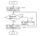
- the conductivity of the first unused rinse liquid flowing through the pipe 611 is continuously measured by the first conductivity measuring unit 613 (FIG. 4: step S141).
- the measured value by the first conductivity measuring unit 613 that is, the conductivity of the first used rinse liquid. Rate
- the measured value in step S141 is larger than the first threshold value, the first used rinse liquid is guided to the first waste liquid portion 65 and is discarded without performing the purification process (steps S142, S143).
- the concentration of the first chemical liquid contained in the first used rinse liquid decreases and the measurement value by the first conductivity measuring unit 613 also decreases.
- the first used rinse liquid is guided to the first purification unit 61, and the first purification unit 61 performs a purification process including dilution with respect to the first used rinse liquid. (Steps S142, S144).
- the first regenerated rinse liquid that can be reused during the first rinse process on the substrate 9 is generated.
- the first regenerated rinse liquid is used, for example, as the first rinse liquid supplied to the substrate 9 during the above-described first rinse treatment of the substrate 9 or the subsequent substrate.
- step S15 When the first rinsing process on the substrate 9 is completed, the acidic second chemical liquid is supplied from the second nozzle 52 to the rotating substrate 9. Then, the supply of the second chemical liquid is continued for a predetermined time, so that the second chemical liquid treatment (for example, the cleaning treatment by SC2) is performed on the substrate 9 (step S15).
- the second chemical liquid treatment for example, the cleaning treatment by SC2
- step S15 may be performed in parallel with the above-described first rinse liquid purification process.
- the second rinse liquid is supplied to the rotating substrate 9 from the second nozzle 52. Then, the second rinse processing is performed on the substrate 9 by continuing the supply of the second rinse liquid for a predetermined time (step S16).
- the second rinse liquid used in the second rinse treatment and scattered from the substrate 9 to the surroundings (that is, the second unused rinse liquid) is received by the second cup 42 of the cup portion 4, and is rinsed outside the housing 11. It is guided to the refining unit 6 and collected (step S17).
- the conductivity of the second unused rinse liquid flowing through the pipe 621 is continuously measured by the second conductivity measuring unit 623 (FIG. 5: step S171).
- the value measured by the second conductivity measuring unit 623 is relatively high.
- the second used rinse liquid is guided to the second waste liquid portion 66 and is discarded without performing the purification process (steps S172 and S173).
- the concentration of the second chemical liquid contained in the second used rinse liquid decreases and the measurement value by the second conductivity measuring unit 623 also decreases.
- the second used rinse liquid is guided to the second purification unit 62, and the second purification unit 62 performs a purification process including dilution with respect to the second used rinse liquid. (Steps S172, S174).
- a second regenerated rinse liquid that can be reused during the second rinse process on the substrate 9 is generated.
- the second regenerated rinse liquid is used, for example, as the second rinse liquid supplied to the substrate 9 during the above-described second rinse treatment of the substrate 9 or the subsequent substrate.
- step S18 the drying process, the rotation speed of the substrate 9 is increased, and the processing liquid remaining on the substrate 9 is scattered from the edge of the substrate 9 radially outward by the centrifugal force and is removed from the substrate 9.
- the processing liquid scattered from the substrate 9 is received by the second cup 42 of the cup portion 4 and discharged to the outside of the housing 11.
- the processes of steps S11 to S18 described above are sequentially performed on the plurality of substrates 9.
- the purification process of the first rinse liquid and the second rinse liquid does not necessarily have to be performed, and even if the purification process is performed only for one of the first rinse liquid and the second rinse liquid. Good.
- the first rinse liquid and the second rinse liquid are not distinguished from each other and one of the first rinse liquid and the second rinse liquid is referred to, it is also simply referred to as “rinse liquid”.
- the first used rinse liquid and the second used rinse liquid are also referred to as “used rinse liquid”.
- the first regenerated rinse liquid and the second regenerated rinse liquid are also referred to as “regenerated rinse liquid”. Is.
- the first chemical liquid and the second chemical liquid are also referred to as “chemical liquid”.
- first rinse process when referring to either one of the first rinse process and the second rinse process, it is simply referred to as “rinse process”.
- first chemical liquid treatment and the second chemical liquid treatment are also referred to as “chemical liquid treatment”.
- first rinse liquid supply unit 55 and the second rinse liquid supply unit 57 are not distinguished, they are simply referred to as “rinse liquid supply unit”.
- first chemical liquid supply unit 54 and the second chemical liquid supply unit 56 are also referred to as “chemical liquid supply unit”.
- the first conductivity measuring unit 613 and the second conductivity measuring unit 623 are also referred to as “conductivity measuring unit”.
- the substrate processing apparatus 1 includes the substrate holding unit 31, the chemical liquid supply unit, the rinse liquid supply unit, and the rinse liquid purification unit 6.
- the substrate holding unit 31 holds the substrate 9 in a horizontal state.
- the chemical liquid supply unit supplies the chemical liquid to the substrate 9 during the chemical liquid treatment of the substrate 9.
- the rinse liquid supply unit supplies the rinse liquid to the substrate 9 when the substrate 9 is rinsed.
- the rinse liquid refining unit 6 performs a purification process including dilution on the used rinse liquid that is the used rinse liquid used for the rinse treatment to generate a reusable regenerated rinse liquid. As a result, the used rinse liquid can be regenerated. As a result, the amount of rinse liquid used can be reduced.
- the regenerated rinse liquid is supplied to the substrate 9 during the rinse process. As a result, the amount of rinse liquid used in the substrate processing apparatus 1 can be reduced.
- the substrate processing apparatus 1 preferably further includes a conductivity measuring unit that measures the conductivity of the used rinse liquid. Then, in a state where the measured value by the conductivity measuring section is larger than the predetermined threshold value, the used rinse liquid is discarded without being subjected to the purification treatment, and when the measured value by the conductivity measuring section becomes equal to or less than the threshold value, the used rinse solution is used.
- the rinse liquid is guided to the rinse liquid refining unit for purification treatment.
- the refining process of the used rinse liquid having a relatively high concentration of the chemical liquid can be avoided, and the burden of the refining process in the rinse liquid refining unit 6 (for example, increase in processing time and flow rate of the diluting rinse liquid) is increased. Can be reduced. As a result, the regenerated rinse liquid can be efficiently generated.
- the rinse liquid purification unit 6 preferably includes the first purification unit 61 and the second purification unit 62.
- the first purification unit 61 performs the purification treatment on the used rinse liquid used in the rinse treatment after the chemical liquid treatment.
- the second purification unit 62 performs the purification treatment on the used rinse liquid used in the rinse treatment after the chemical liquid treatment.
- the substrate processing apparatus 1 further includes the substrate rotating mechanism 33 and the cup section 4.
- the substrate rotation mechanism 33 rotates the substrate holding unit 31 about a central axis J1 that faces the up-down direction.
- the cup part 4 surrounds the periphery of the substrate 9 and receives the liquid scattered around from the rotating substrate 9.
- the cup unit 4 includes a first cup 41, a second cup 42, and a cup switching mechanism 44.
- the chemical liquid used in the chemical liquid treatment is alkaline
- the first cup 41 receives the rinse liquid scattered from the substrate 9 to the surroundings in the rinse treatment after the chemical liquid treatment.
- the chemical liquid used in the chemical liquid treatment is acidic
- the second cup 42 receives the rinse liquid scattered from the substrate 9 to the surroundings in the rinse treatment after the chemical liquid treatment.
- the cup switching mechanism 44 moves at least one of the first cup 41 and the second cup 42 in the up-and-down direction relative to the substrate holding portion 31, thereby moving the first cup 41 and the second cup 42. Any one of them is selectively arranged on the side of the
- the used rinse liquid when used for the rinse treatment after the chemical liquid treatment with the alkaline chemical liquid, the used rinse liquid can be easily delivered to the first purification section 61, and the rinse liquid is acidic.
- the used rinse liquid when used in the rinse treatment after the chemical liquid treatment with the chemical liquid, the used rinse liquid can be easily delivered to the second purification section 62.
- the used rinse liquid sent to the first purification unit 61 and the used rinse liquid sent to the second purification unit 62 can be easily distinguished.
- the cup portion 4 it is possible to prevent the alkaline chemical liquid and the acidic chemical liquid contained in the used rinse liquid from being mixed.
- the substrate processing method described above includes a step of holding the substrate 9 in a horizontal state (step S11), a step of supplying a chemical liquid to the substrate 9 to perform the chemical liquid treatment (step S12), and a rinse liquid on the substrate 9 after step S12. And a step of performing a rinsing process (step S13), and a used rinsing liquid that is the used rinsing liquid used in step S13 is subjected to a refining process including dilution to be reusable. A step of generating a regenerated rinse liquid (step S144). The used rinse solution can be regenerated by the substrate processing method.
- steps S15, S16, and S174 may be performed in addition to steps S12, S13, and S144, or instead of steps S12, S13, and S144.
- the substrate processing method further includes a step (step S141) of measuring the conductivity of the used rinse liquid before the step S144 described above. Then, in the state where the measured value in step S141 is larger than the predetermined threshold value, step S144 is not performed and the used rinse liquid is discarded, and when the measured value in step S141 becomes equal to or less than the threshold value, step S144 is performed. ..
- steps S171 and S174 may be performed in addition to steps S141 and S144 or instead of steps S141 and S144.
- the pipe 614 that guides the first regenerated rinse liquid from the first purification unit 61 to the first rinse liquid supply unit 55 is unused from the first rinse liquid supply source 552 to the first nozzle 51.
- the first regenerated rinse liquid is joined to the pipe 551 for guiding the first rinse liquid and is discharged from the first nozzle 51 that discharges the unused first rinse liquid, but the present invention is not limited to this.
- the pipe 614 for guiding the first regenerating rinse liquid from the first refining unit 61 to the first rinse liquid supplying unit 55 is connected to another nozzle different from the first nozzle 51, and the first regenerating rinse liquid is connected to the other nozzle. It may be discharged from the nozzle toward the substrate 9.
- the first nozzle 51 and the pipe 551 are referred to as “unused rinse liquid discharge part” and “unused rinse liquid pipe”, and the other nozzles and pipes 614 are referred to as “regenerated rinse liquid discharge part” and “regenerated rinse liquid”.
- the first rinse liquid supply unit 55 includes an unused rinse liquid discharge unit, an unused rinse liquid pipe, a recycled rinse liquid discharge unit and a recycled rinse liquid pipe. The same applies to the second rinse liquid supply unit 57.
- the rinse liquid supply unit preferably includes the unused rinse liquid discharge unit, the unused rinse liquid pipe, the recycled rinse liquid discharge unit, and the recycled rinse liquid pipe.
- the unused rinse liquid discharger discharges the unused rinse liquid toward the substrate 9.
- the unused rinse liquid pipe guides the unused rinse liquid from the supply source to the unused rinse liquid discharge part.
- the regeneration rinse liquid ejecting unit ejects the regeneration rinse liquid toward the substrate.
- the regenerated rinse liquid pipe guides the regenerated rinse liquid from the rinse liquid purification unit to the regenerated rinse liquid discharge unit independently of the unused rinse liquid pipe.
- the recycle rinse liquid discharge part for discharging the regenerated rinse liquid is provided independently from the unused rinse liquid discharge part for discharging the unused rinse liquid, and further the pipe connected to the regenerated rinse liquid discharge part is provided.
- the pipe connected to the unused rinse liquid discharge part independent, it is possible to prevent the unused rinse liquid and the regenerated rinse liquid from being mixed in the rinse liquid supply part.
- the used rinse liquid is prevented from being mixed into the rinse liquid, and the purity of the rinse liquid is prevented from lowering. be able to.
- the above-mentioned unused rinse liquid discharge part and regenerated rinse liquid discharge part do not necessarily have to be separate nozzles.
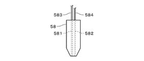
- two independent flow paths 581 and 582 are provided inside one nozzle 58, and one flow path 581 is used as an unused rinse liquid discharge part 581 and the other flow path is used.
- the passage 582 may be used as the regeneration rinse liquid discharger 582.
- the unused rinse liquid ejecting section 581 is connected to an unused rinse liquid pipe 583 that guides the unused rinse liquid from a supply source, and ejects the unused rinse liquid toward the substrate 9.
- the regenerated rinse liquid discharger 582 is connected to the regenerated rinse liquid pipe 584 that guides the regenerated rinse liquid from the rinse liquid refiner, independently of the unused rinse liquid pipe 583, and discharges the regenerated rinse liquid toward the substrate 9. .. Also in this case, similarly to the above, it is possible to prevent the unused rinse liquid and the regenerated rinse liquid from being mixed in the rinse liquid supply unit.
- the first nozzle 51 and the second nozzle 52 of the substrate processing apparatus 1 may discharge the processing liquid toward the lower surface of the substrate 9.
- a lower nozzle that supplies the processing liquid toward the lower surface of the substrate 9 is provided in addition to the first nozzle 51 and the second nozzle 52 that supply the processing liquid toward the upper surface 91 of the substrate 9, a lower nozzle that supplies the processing liquid toward the lower surface of the substrate 9 is provided. You may be asked.
- the lower nozzle is provided, for example, inside the shaft of the substrate rotating mechanism 33, and supplies the processing liquid toward the central portion of the lower surface of the substrate 9.
- the rinse liquid supplied to the lower surface of the substrate 9 may be an unused rinse liquid or a regenerated rinse liquid.
- the unused rinse liquid is discharged from the unused rinse liquid discharge portion toward the lower surface of the substrate 9, and the recycled rinse liquid is discharged from the recycled rinse liquid discharge portion toward the lower surface of the substrate 9. May be.
- the first used rinse liquid used in the first rinse treatment after the first chemical liquid treatment with the alkaline first chemical liquid and the second rinse after the second chemical liquid treatment with the acidic second chemical liquid are used.
- the second unused rinse liquid used in the treatment does not necessarily have to be separated by receiving the liquid by the first cup 41 and the second cup 42 of the cup portion 4.
- the first unused rinse liquid and the second unused rinse liquid are received in the same cup, and the switching valve provided on the pipe leading to the rinse liquid purification unit 6 allows the first unused rinse liquid to be supplied. May be guided to the first purification section 61, and the second unused rinse liquid may be guided to the second purification section 62. Even in this case, the used rinse liquid sent to the first purification unit 61 and the used rinse liquid sent to the second purification unit 62 can be easily distinguished.
- the conductivity measurement of the used rinse liquid by the conductivity measuring unit does not necessarily have to be performed on the used rinse liquid flowing through the pipe, and is temporarily stored in, for example, a tank. It may be performed on the used rinse liquid before dilution.
- the conductivity measurement of the used rinse liquid is not necessarily performed by the conductivity measurement unit.
- the time from the start of the rinse treatment until the conductivity of the used rinse liquid falls below a predetermined threshold value (hereinafter, referred to as “waiting time”) is measured in advance, and the waiting time from the start of the rinse treatment is measured.
- the used rinse liquid may be discarded until the time elapses, and after the waiting time elapses, the purification process for the used rinse liquid may be started.
- the used rinse liquid may be sent to the rinse liquid purification unit 6 immediately after the start of the rinse treatment, and the used rinse liquid may be purified.
- the processing content of the substrate 9 in the substrate processing apparatus 1 is not limited to the above example and may be variously modified.
- the cleaning treatment on the substrate 9 with hydrofluoric acid, the cleaning treatment with SC1, and the cleaning treatment with SC2 may be sequentially performed.
- the used rinse liquid used for the rinse treatment after the acidic hydrofluoric acid cleaning treatment and the used rinse liquid used for the rinse treatment after the acidic SC2 cleaning treatment are the second purification unit 62.
- the used rinse liquid used for the rinse treatment after the cleaning treatment with the alkaline SC1 may be guided to the first purification unit 61 and subjected to the purification treatment.
- the used rinse liquid used in the rinse treatment after the chemical liquid treatment with the alkaline chemical liquid and the used rinse liquid used in the rinse treatment after the chemical liquid treatment with the acidic chemical liquid are not always required. It need not be purified separately. For example, these two kinds of used rinse liquids may be subjected to a purification treatment in the same purification unit.
- the regenerated rinse liquid purified by the rinse liquid purification unit 6 is used for the rinse treatment of a predetermined number of substrates 9 and then discarded. Good. Further, in the substrate processing apparatus 1, only the unused rinse liquid may be used in the rinse process immediately before the drying process of the substrate 9. In the substrate processing apparatus 1, the regenerated rinse liquid may not be used for the rinse processing of the substrate 9 but may be used in another apparatus.
- the substrate processing apparatus 1 described above is used for a glass substrate used for a flat panel display (Flat Panel Display) such as a liquid crystal display device or an organic EL (Electro Luminescence) display device, or another display device other than the semiconductor substrate. It may be used for processing a glass substrate. Further, the substrate processing apparatus 1 described above may be used for processing optical disk substrates, magnetic disk substrates, magneto-optical disk substrates, photomask substrates, ceramic substrates, solar cell substrates, and the like.
- a flat panel display such as a liquid crystal display device or an organic EL (Electro Luminescence) display device, or another display device other than the semiconductor substrate. It may be used for processing a glass substrate. Further, the substrate processing apparatus 1 described above may be used for processing optical disk substrates, magnetic disk substrates, magneto-optical disk substrates, photomask substrates, ceramic substrates, solar cell substrates, and the like.
Landscapes
- Cleaning Or Drying Semiconductors (AREA)
Abstract
基板処理装置(1)は、基板保持部(31)と、薬液供給部と、リンス液供給部と、リンス液精製部(6)とを備える。基板保持部(31)は、水平状態で基板(9)を保持する。薬液供給部は、基板(9)の薬液処理の際に基板(9)に薬液を供給する。リンス液供給部は、基板(9)のリンス処理の際に、基板(9)にリンス液を供給する。リンス液精製部(6)は、当該リンス処理に使用された使用済みのリンス液である既使用リンス液に対して、希釈を含む精製処理を行って再使用可能な再生リンス液を生成する。これにより、使用済みのリンス液を再生することができる。
Description
本発明は、基板処理装置および基板処理方法に関する。
従来、半導体基板(以下、単に「基板」という。)の製造工程では、基板に対して様々な処理が施される。例えば、特開2010-287591号公報(文献1)のバッチ式の基板処理装置では、複数(例えば、50枚)の基板を処理槽内の薬液に浸漬して薬液処理が行われた後、処理槽内の薬液を純水に置換し、当該純水に基板を浸漬するリンス処理が行われる。当該基板処理装置では、リンス処理が行われている間に、処理槽から排出される排液の濃度が所定濃度よりも小さくなると、当該排液を回収して再利用する。文献1では、薬液処理で用いられる薬液の種類に応じて、リンス処理の際の排液回収を別々に行うことにより、排液の回収量を増大させて純水の使用量を低減することが提案されている。
ところで、文献1の基板処理装置では、排液の濃度が再利用可能な所定濃度に低下するまで排液を廃棄しているため、排液の回収量増大に限界がある。また、文献1では、基板を1枚ずつ処理する枚葉式の基板処理装置については考慮されていない。
本発明は、枚葉式の基板処理装置に向けられており、、使用済みのリンス液を再生することを目的としている。
本発明の好ましい一の形態に係る基板処理装置は、水平状態で基板を保持する基板保持部と、前記基板の薬液処理の際に前記基板に薬液を供給する薬液供給部と、前記基板のリンス処理の際に前記基板にリンス液を供給するリンス液供給部と、前記リンス処理に使用された使用済みのリンス液である既使用リンス液に対して希釈を含む精製処理を行って再使用可能な再生リンス液を生成するリンス液精製部とを備える。これにより、使用済みのリンス液を再生することができる。
好ましくは、前記リンス液精製部は、前記薬液処理にて使用される前記薬液がアルカリ性である場合、前記薬液処理後の前記リンス処理にて使用された前記既使用リンス液に対する前記精製処理を行う第1精製部と、前記薬液処理にて使用される前記薬液が酸性である場合、前記薬液処理後の前記リンス処理にて使用された前記既使用リンス液に対する前記精製処理を行う第2精製部とを備える。
好ましくは、前記基板処理装置は、上下方向を向く中心軸を中心として前記基板保持部を回転する基板回転機構と、前記基板の周囲を囲み、回転する前記基板から周囲に飛散する液体を受けるカップ部とをさらに備える。前記カップ部は、前記薬液処理にて使用される前記薬液がアルカリ性である場合、前記薬液処理後の前記リンス処理の際に前記基板から周囲に飛散するリンス液を受ける第1カップと、前記薬液処理にて使用される前記薬液が酸性である場合、前記薬液処理後の前記リンス処理の際に前記基板から周囲に飛散するリンス液を受ける第2カップと、前記第1カップおよび前記第2カップのうち少なくとも一方のカップを前記基板保持部に対して上下方向に相対的に移動することにより、前記第1カップおよび前記第2カップのいずれかを選択的に前記基板の側方に配置するカップ切替機構とを備える。
好ましくは、前記基板処理装置は、前記既使用リンス液の導電率を測定する導電率測定部をさらに備える。前記導電率測定部による測定値が所定の閾値よりも大きい状態では、前記既使用リンス液は前記精製処理が行われることなく廃棄される。前記導電率測定部による測定値が前記閾値以下になると、前記既使用リンス液は前記リンス液精製部へと導かれて前記精製処理が行われる。
好ましくは、前記リンス処理の際に前記再生リンス液が前記基板に供給される。
好ましくは、前記リンス液供給部は、未使用のリンス液を前記基板に向けて吐出する未使用リンス液吐出部と、前記未使用のリンス液を供給源から前記未使用リンス液吐出部へと導く未使用リンス液配管と、前記再生リンス液を前記基板に向けて吐出する再生リンス液吐出部と、前記未使用リンス液配管とは独立して前記リンス液精製部から前記再生リンス液を前記再生リンス液吐出部へと導く再生リンス液配管とを備える。
本発明は、基板処理方法にも向けられている。本発明の好ましい一の形態に係る基板処理方法は、a)基板を水平状態で保持する工程と、b)前記基板に薬液を供給して薬液処理を行う工程と、c)前記b)工程の後に前記基板にリンス液を供給してリンス処理を行う工程と、d)前記c)工程にて使用された使用済みのリンス液である既使用リンス液に対して希釈を含む精製処理を行って再使用可能な再生リンス液を生成する工程とを備える。これにより、使用済みのリンス液を再生することができる。
好ましくは、前記d)工程において、前記薬液処理にて使用される前記薬液がアルカリ性である場合、第1精製部において前記既使用リンス液に対する前記精製処理が行われ、前記薬液処理にて使用される前記薬液が酸性である場合、前記第1精製部とは異なる第2精製部において前記既使用リンス液に対する前記精製処理が行われる。
好ましくは、前記c)工程において、前記リンス液は、上下方向を向く中心軸を中心として回転する前記基板に供給される。回転する前記基板から周囲に飛散するリンス液は、前記b)工程にて使用される前記薬液がアルカリ性である場合、前記基板の周囲を囲む第1カップにより受けられ、前記b)工程にて使用される前記薬液が酸性である場合、前記基板の周囲を囲む第2カップにより受けられる。
好ましくは、前記基板処理方法は、e)前記d)工程よりも前に、前記既使用リンス液の導電率を測定する工程をさらに備える。前記e)工程における測定値が所定の閾値よりも大きい状態では、前記d)工程は行われることなく、前記既使用リンス液は廃棄される。前記e)工程における測定値が前記閾値以下になると、前記d)工程が行われる。
好ましくは、前記c)工程において前記再生リンス液が前記基板に供給される。
好ましくは、前記c)工程において、リンス液供給部から前記基板にリンス液が供給される。前記リンス液供給部は、未使用のリンス液を前記基板に向けて吐出する未使用リンス液吐出部と、前記未使用のリンス液を供給源から前記未使用リンス液吐出部へと導く未使用リンス液配管と、前記再生リンス液を前記基板に向けて吐出する再生リンス液吐出部と、前記未使用リンス液配管とは独立して前記再生リンス液を前記再生リンス液吐出部へと導く再生リンス液配管とを備える。
上述の目的および他の目的、特徴、態様および利点は、添付した図面を参照して以下に行うこの発明の詳細な説明により明らかにされる。
図1は、本発明の一の実施の形態に係る基板処理装置1の構成を示す側面図である。基板処理装置1は、半導体基板9(以下、単に「基板9」という。)を1枚ずつ処理する枚葉式の装置である。基板処理装置1は、基板9に処理液を供給して処理を行う。図1では、基板処理装置1の構成の一部を断面にて示す。
基板処理装置1は、基板保持部31と、基板回転機構33と、カップ部4と、処理液供給部5と、リンス液精製部6と、ハウジング11とを備える。基板保持部31、基板回転機構33およびカップ部4等は、ハウジング11の内部空間に収容される。リンス液精製部6は、ハウジング11の外部に配置される。
基板保持部31は、水平状態の基板9の下側の主面(すなわち、下面)と対向し、基板9を下側から保持する。基板保持部31は、例えば、基板9を機械的に支持するメカニカルチャックである。基板保持部31は、上下方向を向く中心軸J1を中心として回転可能に設けられる。
基板保持部31は、保持部本体と、複数のチャックピンとを備える。保持部本体は、基板9の下面と対向する略円板状の部材である。複数のチャックピンは、保持部本体の周縁部にて中心軸J1を中心とする周方向(以下、単に「周方向」とも呼ぶ。)に略等角度間隔にて配置される。各チャックピンは、保持部本体の上面から上方へと突出し、基板9の下面の周縁領域および側面に接触して基板9を支持する。なお、基板保持部31は、基板9の下面中央部を吸着して保持するバキュームチャック等であってもよい。
基板回転機構33は、基板保持部31の下方に配置される。基板回転機構33は、中心軸J1を中心として基板9を基板保持部31と共に回転する。基板回転機構33は、例えば、回転シャフトが基板保持部31の保持部本体に接続された電動モータを備える。基板回転機構33は、中空モータ等の他の構造を有していてもよい。
処理液供給部5は、基板9に複数種類の処理液を個別に供給する。当該複数種類の処理液には、例えば、後述する薬液およびリンス液等が含まれる。処理液供給部5は、第1ノズル51と、第2ノズル52とを備える。第1ノズル51および第2ノズル52はそれぞれ、基板9の上方から基板9の上側の主面(以下、「上面91」という。)に向けて処理液を供給する。
図1に示す状態では、第1ノズル51が基板9の中央部の上方に位置し、第1ノズル51から基板9の中央部に処理液の供給が行われる。このとき、第2ノズル52は、中心軸J1を中心とする径方向(以下、単に「径方向」とも呼ぶ。)において、基板9のエッジ(すなわち、周縁)よりも外側の退避位置へと退避している。第2ノズル52から基板9に処理液の供給が行われる際には、第1ノズル51が基板9のエッジよりも径方向外側の退避位置へと退避し、第2ノズル52が基板9の中央部の上方に位置する。図1に示す例では、第1ノズル51および第2ノズル52の退避位置はそれぞれ、カップ部4の径方向外側に位置する。
カップ部4は、回転中の基板9から周囲に向かって飛散する処理液等の液体を受ける受液容器である。カップ部4は、基板9および基板保持部31の周囲において全周に亘って配置され、基板9および基板保持部31の側方を覆う。カップ部4は、基板9の回転および静止に関わらず、周方向において静止している。カップ部4の底部には、カップ部4にて受けられた処理液等をハウジング11の外部へと排出する排液ポート411,421が設けられる。
カップ部4は、径方向に間隔を空けて積層される複数のカップ要素を備える。図1に示す例では、カップ部4は、第1カップ41と、第2カップ42とを、2つのカップ要素として備える。第1カップ41および第2カップ42はそれぞれ、中心軸J1を中心とする略円環状の部材である。第1カップ41は、第2カップ42の径方向内側に位置する。第1カップ41および第2カップ42の内側面は、例えば撥水性材料により形成される。なお、カップ部4が備えるカップ要素の数は、適宜変更されてよい。
カップ部4は、カップ切替機構44をさらに備える。カップ切替機構44は、第1カップ41を上下方向に移動するカップ昇降機構である。カップ切替機構44は、例えば、第1カップ41に接続されるエアシリンダまたは電動リニアモータを備える。カップ切替機構44は、第1カップ41を、図1に示す受液位置と、受液位置の下方の退避位置との間で上下方向に移動する。第1カップ41が基板9の側方の受液位置に位置する状態では、回転中の基板9から周囲に飛散する液体は、第1カップ41により受けられる。また、第1カップ41が上記退避位置に位置する状態では、第2カップ42が基板9の側方に位置し、回転中の基板9から周囲に飛散する液体は、第2カップ42により受けられる。すなわち、カップ切替機構44は、第1カップ41を上下方向に移動することにより、第2カップ42および第1カップ41のいずれかを選択的に基板9の側方に配置する。
なお、カップ部4では、第2カップ42が第1カップ41の径方向内側に配置されてもよい。この場合、カップ切替機構44は、第2カップ42を受液位置と退避位置との間で上下方向に移動する。また、カップ切替機構44は、第2カップ42および第1カップ41の双方を個別に上下方向に移動してもよく、基板保持部31を上下方向に移動してもよい。換言すれば、カップ切替機構44は、第1カップ41および第2カップ42のうち少なくとも一方のカップを、基板保持部31に対して上下方向に相対的に移動することにより、第1カップ41および第2カップ42のいずれかを選択的に基板9の側方に配置する。
図2は、基板処理装置1の処理液供給部5およびリンス液精製部6を示すブロック図である。図2では、処理液供給部5およびリンス液精製部6以外の構成も併せて示す。処理液供給部5は、第1薬液供給部54と、第1リンス液供給部55と、第2薬液供給部56と、第2リンス液供給部57とを備える。リンス液精製部6は、第1精製部61と、第2精製部62と、第1循環機構63と、第2循環機構64とを備える。第2精製部62は、第1精製部61から独立した第1精製部61とは異なる精製部である。
第1薬液供給部54は、第1ノズル51と、配管541と、第1薬液供給源542と、バルブ543とを備える。第1薬液供給源542には、未使用の第1薬液が貯溜されている。第1ノズル51は、配管541を介して第1薬液供給源542に接続される。第1薬液供給部54では、配管541上に設けられたバルブ543が開かれることにより、第1薬液供給源542から第1ノズル51に第1薬液が送出される。そして、第1ノズル51から基板9に第1薬液が供給されることにより、基板9に対する第1薬液処理が行われる。第1ノズル51は、第1薬液を基板9に向けて吐出する第1薬液吐出部である。
第1薬液処理にて使用される第1薬液は、アルカリ性の薬液である。第1薬液は、例えば、基板9の洗浄処理に使用されるSC1(すなわち、アンモニア水と過酸化水素水とDIW(De-ionized Water)との混合液)等の洗浄液である。第1薬液は、洗浄液以外の薬液であってもよい。第1薬液処理にて使用された使用済みの第1薬液は、基板9の回転により基板9から周囲へと飛散し、カップ部4の第1カップ41により受けられる。第1カップ41により受けられた第1薬液は、第1カップ41の底部に設けられた第1排出ポート411を介してハウジング11(図1参照)の外部へと排出される。ハウジング11から排出された第1薬液は、切替バルブ13により第1薬液回収部14へと導かれる。
第1リンス液供給部55は、第1ノズル51と、配管551と、第1リンス液供給源552と、バルブ553とを備える。第1リンス液供給部55は、第1ノズル51を第1薬液供給部54と共有する。第1リンス液供給部55には、未使用の第1リンス液が貯溜されている。第1ノズル51は、配管551を介して第1リンス液供給源552に接続される。第1リンス液供給部55では、配管551上に設けられたバルブ553が開かれることにより、第1リンス液供給源552から第1ノズル51に第1リンス液が送出される。そして、第1ノズル51から基板9に第1リンス液が供給されることにより、基板9に対する第1リンス処理が行われる。第1ノズル51は、第1リンス液を基板9に向けて吐出する第1リンス液吐出部である。
第1リンス処理にて使用される第1リンス液は、例えば、DIW、炭酸水、オゾン水または水素水等の水性処理液が利用される。本実施の形態では、DIWが第1リンス液として利用される。第1リンス処理にて使用された使用済みの第1リンス液は、基板9の回転により基板9から周囲へと飛散し、カップ部4の第1カップ41により受けられる。第1カップ41により受けられた第1リンス液は、第1カップ41の底部に設けられた第1排出ポート411を介してハウジング11(図1参照)の外部へと排出される。
ハウジング11から排出された使用済みの第1リンス液(以下、「第1既使用リンス液」とも呼ぶ。)は、切替バルブ13により配管611へと送出される。配管611は、切替バルブ612を介して第1精製部61および第1廃液部65に接続される。配管611の切替バルブ13と切替バルブ612との間には、第1導電率測定部613が設けられる。第1導電率測定部613は、切替バルブ13から切替バルブ612に向けて配管611を流れる第1既使用リンス液の導電率を測定する。第1導電率測定部613の測定値(すなわち、第1既使用リンス液の導電率)が所定の閾値である第1閾値よりも大きい状態では、配管611は切替バルブ612により第1廃液部65に接続される。配管611を流れる第1既使用リンス液は第1廃液部65へと導かれ、後述する精製処理が行われることなく廃棄される。
一方、第1導電率測定部613の測定値(すなわち、第1既使用リンス液の導電率)が第1閾値以下の状態では、配管611は切替バルブ612により第1精製部61に接続される。配管611を流れる第1既使用リンス液は第1精製部61へと導かれ、第1精製部61において第1既使用リンス液に対する希釈を含む精製処理が行われる。第1精製部61では、例えば、フィルタ等による濾過によって異物が除去された第1既使用リンス液が、第1精製タンクに一時的に貯溜され、第1精製タンク内の第1既使用リンス液に未使用の第1リンス液(例えば、DIW)が添加されることにより、第1既使用リンス液の希釈処理が行われる。第1精製部61では、当該希釈処理に加えて、様々な精製処理が行われてよい。第1精製部61では、第1既使用リンス液に対する精製処理が行われることにより、基板9に対するリンス処理の際に再使用可能な第1再生リンス液が生成される。
第1再生リンス液は、第1循環機構63により、配管614を介して第1リンス液供給部55へと送られる。第1循環機構63は、例えば、第1再生リンス液を圧送するポンプを備える。配管614は、第1リンス液供給部55において、第1リンス液供給源552とバルブ553との間で配管551に接続される。第1再生リンス液は、配管551を介して第1ノズル51へと送出される。そして、第1ノズル51から基板9に第1再生リンス液が供給されることにより、基板9に対する第1リンス処理が行われる。換言すれば、基板9に対する第1リンス処理において、第1精製部61にて精製処理が施された第1リンス液(すなわち、第1再生リンス液)が再使用される。
当該第1リンス処理では、例えば、第1再生リンス液のみが使用されてもよく、第1再生リンス液に第1リンス液供給源552からの未使用の第1リンス液が混合された状態で使用されてもよい。また、第1リンス処理の前半を第1再生リンス液のみにより行い、第1リンス処理の後半を未使用の第1リンス液のみにより行ってもよい。上述のように、基板9に対する第1リンス処理の全体に亘って、未使用の第1リンス液のみを使用することも可能である。
第2薬液供給部56は、第2ノズル52と、配管561と、第2薬液供給源562と、バルブ563とを備える。第2薬液供給源562には、未使用の第2薬液が貯溜されている。第2ノズル52は、配管561を介して第2薬液供給源562に接続される。第2薬液供給部56では、配管561上に設けられたバルブ563が開かれることにより、第2薬液供給源562から第2ノズル52に第2薬液が送出される。そして、第2ノズル52から基板9に第2薬液が供給されることにより、基板9に対する第2薬液処理が行われる。第2ノズル52は、第2薬液を基板9に向けて吐出する第2薬液吐出部である。
第2薬液処理にて使用される第2薬液は、酸性の薬液である。第2薬液は、例えば、基板9の洗浄処理に使用されるSC2(すなわち、塩酸と過酸化水素水とDIWとの混合液)等の洗浄液である。第2薬液は、洗浄液以外の薬液であってもよい。第2薬液処理にて使用された使用済みの第2薬液は、基板9の回転により基板9から周囲へと飛散し、カップ部4の第2カップ42により受けられる。このとき、第1カップ41はカップ切替機構44により図2に示す受液位置よりも下側の退避位置に位置している。第2カップ42により受けられた第2薬液は、第2カップ42の底部に設けられた第2排出ポート421を介してハウジング11(図1参照)の外部へと排出される。ハウジング11から排出された第2薬液は、切替バルブ15により第2薬液回収部16へと導かれる。
第2リンス液供給部57は、第2ノズル52と、配管571と、第2リンス液供給源572と、バルブ573とを備える。第2リンス液供給部57は、第2ノズル52を第2薬液供給部56と共有する。第2リンス液供給部57には、未使用の第2リンス液が貯溜されている。第2ノズル52は、配管571を介して第2リンス液供給源572に接続される。第2リンス液供給部57では、配管571上に設けられたバルブ573が開かれることにより、第2リンス液供給源572から第2ノズル52に第2リンス液が送出される。そして、第2ノズル52から基板9に第2リンス液が供給されることにより、基板9に対する第2リンス処理が行われる。第2ノズル52は、第2リンス液を基板9に向けて吐出する第2リンス液吐出部である。
第2リンス処理にて使用される第2リンス液は、例えば、DIW、炭酸水、オゾン水または水素水等の水性処理液が利用される。本実施の形態では、DIWが第2リンス液として利用される。すなわち、本実施の形態では、第2リンス液は第1リンス液と同じ種類の液体である。第2リンス処理にて使用された使用済みの第2リンス液は、基板9の回転により基板9から周囲へと飛散し、カップ部4の第2カップ42により受けられる。第2カップ42により受けられた第2リンス液は、第2カップ42の底部に設けられた第2排出ポート421を介してハウジング11(図1参照)の外部へと排出される。
ハウジング11から排出された使用済みの第2リンス液(以下、「第2既使用リンス液」とも呼ぶ。)は、切替バルブ15により配管621へと送出される。配管621は、切替バルブ622を介して第2精製部62および第2廃液部66に接続される。配管621の切替バルブ15と切替バルブ622との間には、第2導電率測定部623が設けられる。第2導電率測定部623は、切替バルブ15から切替バルブ622に向けて配管621を流れる第2既使用リンス液の導電率を測定する。第2導電率測定部623の測定値(すなわち、第2既使用リンス液の導電率)が所定の閾値である第2閾値よりも大きい状態では、配管621は切替バルブ622により第2廃液部66に接続される。配管621を流れる第2既使用リンス液は第2廃液部66へと導かれ、後述する精製処理が行われることなく廃棄される。第2閾値は、上述の第1閾値と異なっていてもよく、同じであってもよい。
一方、第2導電率測定部623の測定値(すなわち、第2既使用リンス液の導電率)が第2閾値以下の状態では、配管621は切替バルブ622により第2精製部62に接続される。配管621を流れる第2既使用リンス液は第2精製部62へと導かれ、第2精製部62において第2既使用リンス液に対する希釈を含む精製処理が行われる。第2精製部62では、例えば、フィルタ等による濾過によって異物が除去された第2既使用リンス液が、第2精製タンクに一時的に貯溜され、第2精製タンク内の第2既使用リンス液に未使用の第2リンス液(例えば、DIW)が添加されることにより、第2既使用リンス液の希釈処理が行われる。第2精製部62では、当該希釈処理に加えて、様々な精製処理が行われてよい。第2精製部62では、第2既使用リンス液に対する精製処理が行われることにより、基板9に対するリンス処理の際に再使用可能な第2再生リンス液が生成される。
第2再生リンス液は、第2循環機構64により、配管624を介して第2リンス液供給部57へと送られる。第2循環機構64は、例えば、第2再生リンス液を圧送するポンプを備える。配管624は、第2リンス液供給部57において、第2リンス液供給源572とバルブ573との間で配管571に接続される。第2再生リンス液は、配管571を介して第2ノズル52へと送出される。そして、第2ノズル52から基板9に第2再生リンス液が供給されることにより、基板9に対する第2リンス処理が行われる。換言すれば、基板9に対する第2リンス処理において、第2精製部62にて精製処理が施された第2リンス液(すなわち、第2再生リンス液)が再使用される。
当該第2リンス処理では、例えば、第2再生リンス液のみが使用されてもよく、第2再生リンス液に第2リンス液供給源572からの未使用の第2リンス液が混合された状態で使用されてもよい。また、第2リンス処理の前半を第2再生リンス液のみにより行い、第2リンス処理の後半を未使用の第2リンス液のみにより行ってもよい。上述のように、基板9に対する第2リンス処理の全体に亘って、未使用の第2リンス液のみを使用することも可能である。
基板処理装置1では、第1リンス液と第2リンス液とが同じ種類の液体である場合、第1ノズル51に接続される配管551と、第2ノズル52に接続される配管571とは、同一のリンス液供給源に接続されてもよい。換言すれば、当該リンス液供給源は、第1リンス液供給部55と第2リンス液供給部57とに共有されてもよい。また、この場合、第1リンス液および第2リンス液は、同一のノズルから基板9に向けて吐出されてもよい。
基板処理装置1における基板9の処理は、例えば、第1薬液処理、第1リンス処理、第2薬液処理、第2リンス処理および乾燥処理の順で行われる。図3は、基板処理装置1における基板9の処理の流れの一例を示す図である。また、図4および図5はそれぞれ、基板9の当該処理における流れの一部の詳細を示す図である。
具体的には、まず、基板保持部31により基板9が水平状態で保持される(ステップS11)。続いて、基板9の回転が開始され、回転中の基板9に対して第1ノズル51からアルカリ性の第1薬液が供給される。そして、第1薬液の供給が所定時間継続されることにより、基板9に対する第1薬液処理(例えば、SC1による洗浄処理)が行われる(ステップS12)。第1薬液処理において基板9から周囲に飛散する第1薬液は、カップ部4の第1カップ41により受けられ、ハウジング11の外部の第1薬液回収部14へと導かれる。
基板9に対する第1薬液処理が終了すると、回転中の基板9に対して第1ノズル51から第1リンス液が供給される。そして、第1リンス液の供給が所定時間継続されることにより、基板9に対する第1リンス処理が行われる(ステップS13)。第1リンス処理に使用されて基板9から周囲に飛散する第1リンス液(すなわち、第1既使用リンス液)は、カップ部4の第1カップ41により受けられ、ハウジング11の外部のリンス液精製部6へと導かれて回収される(ステップS14)。
リンス液精製部6では、配管611を流れる第1既使用リンス液の導電率が、第1導電率測定部613により継続的に測定される(図4:ステップS141)。第1リンス処理の開始直後は、第1既使用リンス液に含まれる第1薬液の濃度が比較的高いため、第1導電率測定部613による測定値(すなわち、第1既使用リンス液の導電率)は比較的高い。ステップS141における測定値が第1閾値よりも大きい状態では、第1既使用リンス液は第1廃液部65へと導かれ、精製処理が行われることなく廃棄される(ステップS142,S143)。
第1リンス処理の開始から時間が経過すると、第1既使用リンス液に含まれる第1薬液の濃度が減少し、第1導電率測定部613による測定値も小さくなる。ステップS141における測定値が第1閾値以下になると、第1既使用リンス液は第1精製部61へと導かれ、第1精製部61において第1既使用リンス液に対する希釈を含む精製処理が行われる(ステップS142,S144)。これにより、基板9に対する第1リンス処理の際に再使用可能な第1再生リンス液が生成される。第1再生リンス液は、例えば、上述の基板9または後続の基板の第1リンス処理の際に、基板9に供給される第1リンス液として利用される。
基板9に対する第1リンス処理が終了すると、回転中の基板9に対して第2ノズル52から酸性の第2薬液が供給される。そして、第2薬液の供給が所定時間継続されることにより、基板9に対する第2薬液処理(例えば、SC2による洗浄処理)が行われる(ステップS15)。第2薬液処理において基板9から周囲に飛散する第2薬液は、カップ部4の第2カップ42により受けられ、ハウジング11の外部の第2薬液回収部16へと導かれる。なお、ステップS15は、上述の第1リンス液の精製処理と並行して行われてもよい。
基板9に対する第2薬液処理が終了すると、回転中の基板9に対して第2ノズル52から第2リンス液が供給される。そして、第2リンス液の供給が所定時間継続されることにより、基板9に対する第2リンス処理が行われる(ステップS16)。第2リンス処理に使用されて基板9から周囲に飛散する第2リンス液(すなわち、第2既使用リンス液)は、カップ部4の第2カップ42により受けられ、ハウジング11の外部のリンス液精製部6へと導かれて回収される(ステップS17)。
リンス液精製部6では、配管621を流れる第2既使用リンス液の導電率が、第2導電率測定部623により継続的に測定される(図5:ステップS171)。第2リンス処理の開始直後は、第2既使用リンス液に含まれる第2薬液の濃度が比較的高いため、第2導電率測定部623による測定値(すなわち、第2既使用リンス液の導電率)は比較的高い。ステップS171における測定値が第2閾値よりも大きい状態では、第2既使用リンス液は第2廃液部66へと導かれ、精製処理が行われることなく廃棄される(ステップS172,S173)。
第2リンス処理の開始から時間が経過すると、第2既使用リンス液に含まれる第2薬液の濃度が減少し、第2導電率測定部623による測定値も小さくなる。ステップS171における測定値が第2閾値以下になると、第2既使用リンス液は第2精製部62へと導かれ、第2精製部62において第2既使用リンス液に対する希釈を含む精製処理が行われる(ステップS172,S174)。これにより、基板9に対する第2リンス処理の際に再使用可能な第2再生リンス液が生成される。第2再生リンス液は、例えば、上述の基板9または後続の基板の第2リンス処理の際に、基板9に供給される第2リンス液として利用される。
その後、第2リンス処理の供給が停止され、基板9の乾燥処理が行われる(図3:ステップS18)。乾燥処理では、基板9の回転速度が増大され、基板9上に残っている処理液が、遠心力により基板9のエッジから径方向外方へとへと飛散し、基板9上から除去される。基板9上から飛散した処理液は、カップ部4の第2カップ42により受けられ、ハウジング11の外部へと排出される。基板処理装置1では、上述のステップS11~S18の処理が、複数の基板9に対して順次行われる。
基板処理装置1では、必ずしも第1リンス液および第2リンス液の精製処理が行われる必要はなく、第1リンス液および第2リンス液のうち一方のリンス液にだけ精製処理が行われてもよい。以下の説明では、第1リンス液および第2リンス液を区別することなく、第1リンス液および第2リンス液のうちいずれか一方のリンス液を指す場合、単に「リンス液」とも呼ぶ。第1既使用リンス液および第2既使用リンス液についても同様に、「既使用リンス液」とも呼ぶ。第1再生リンス液および第2再生リンス液についても同様に、「再生リンス液」とも呼ぶ。である。第1薬液および第2薬液についても同様に、「薬液」とも呼ぶ。
また、第1リンス処理および第2リンス処理を区別することなく、第1リンス処理および第2リンス処理のうちいずれか一方のリンス処理を指す場合、単に「リンス処理」とも呼ぶ。第1薬液処理および第2薬液処理についても同様に、「薬液処理」とも呼ぶ。これに伴い、第1リンス液供給部55および第2リンス液供給部57を区別しない場合、単に「リンス液供給部」とも呼ぶ。第1薬液供給部54および第2薬液供給部56についても同様に、「薬液供給部」とも呼ぶ。第1導電率測定部613および第2導電率測定部623についても同様に、「導電率測定部」とも呼ぶ。
以上に説明したように、基板処理装置1は、基板保持部31と、薬液供給部と、リンス液供給部と、リンス液精製部6とを備える。基板保持部31は、水平状態で基板9を保持する。薬液供給部は、基板9の薬液処理の際に基板9に薬液を供給する。リンス液供給部は、基板9のリンス処理の際に、基板9にリンス液を供給する。リンス液精製部6は、当該リンス処理に使用された使用済みのリンス液である既使用リンス液に対して、希釈を含む精製処理を行って再使用可能な再生リンス液を生成する。これにより、使用済みのリンス液を再生することができる。その結果、リンス液の使用量を低減することができる。
上述のように、基板処理装置1では、上記リンス処理の際に再生リンス液が基板9に供給されることが好ましい。これにより、基板処理装置1におけるリンス液の使用量を低減することができる。
上述のように、基板処理装置1は、既使用リンス液の導電率を測定する導電率測定部をさらに備えることが好ましい。そして、導電率測定部による測定値が所定の閾値よりも大きい状態では、既使用リンス液は精製処理が行われることなく廃棄され、導電率測定部による測定値が当該閾値以下になると、既使用リンス液はリンス液精製部へと導かれて精製処理が行われる。これにより、薬液の濃度が比較的高い既使用リンス液の精製処理を避けることができ、リンス液精製部6における精製処理の負担(例えば、処理時間の増大や希釈用リンス液の流量増大)を軽減することができる。その結果、再生リンス液を効率良く生成することができる。なお、基板処理装置1では、既使用リンス液の導電率を測定することにより、リンス処理に要する時間の最適化を図ることもできる。
上述のように、リンス液精製部6は、第1精製部61と、第2精製部62とを備えることが好ましい。第1精製部61は、薬液処理にて使用される薬液がアルカリ性である場合、薬液処理後のリンス処理にて使用された既使用リンス液に対する精製処理を行う。第2精製部62は、薬液処理にて使用される薬液が酸性である場合、薬液処理後のリンス処理にて使用された既使用リンス液に対する精製処理を行う。これにより、リンス液精製部6において、既使用リンス液に含まれるアルカリ性の薬液と酸性の薬液とが混ざることを防止することができる。その結果、アルカリ性の薬液と酸性の薬液との化学反応等が生じることを防止することができる。
上述のように、好ましくは、基板処理装置1は、基板回転機構33と、カップ部4とをさらに備える。基板回転機構33は、上下方向を向く中心軸J1を中心として基板保持部31を回転する。カップ部4は、基板9の周囲を囲み、回転する基板9から周囲に飛散する液体を受ける。カップ部4は、第1カップ41と、第2カップ42と、カップ切替機構44とを備える。第1カップ41は、薬液処理にて使用される薬液がアルカリ性である場合、薬液処理後のリンス処理の際に、基板9から周囲に飛散するリンス液を受ける。第2カップ42は、薬液処理にて使用される薬液が酸性である場合、薬液処理後のリンス処理の際に、基板9から周囲に飛散するリンス液を受ける。カップ切替機構44は、第1カップ41および第2カップ42のうち少なくとも一方のカップを基板保持部31に対して上下方向に相対的に移動することにより、第1カップ41および第2カップ42のいずれかを選択的に基板9の側方に配置する。
これにより、リンス液が、アルカリ性の薬液による薬液処理後のリンス処理に使用された場合に、既使用リンス液を容易に第1精製部61へと送出することができ、リンス液が、酸性の薬液による薬液処理後のリンス処理に使用された場合に、既使用リンス液を容易に第2精製部62へと送出することができる。換言すれば、第1精製部61へ送られる既使用リンス液と、第2精製部62へ送られる既使用リンス液とを容易に区別することができる。また、カップ部4において、既使用リンス液に含まれるアルカリ性の薬液と酸性の薬液とが混ざることを防止することもできる。
上述の基板処理方法は、基板9を水平状態で保持する工程(ステップS11)と、基板9に薬液を供給して薬液処理を行う工程(ステップS12)と、ステップS12の後に基板9にリンス液を供給してリンス処理を行う工程(ステップS13)と、ステップS13にて使用された使用済みのリンス液である既使用リンス液に対して、希釈を含む精製処理を行って、再使用可能な再生リンス液を生成する工程(ステップS144)とを備える。当該基板処理方法により、使用済みのリンス液を再生することができる。当該基板処理方法では、ステップS12,S13,S144に加えて、または、ステップS12,S13,S144に代えて、ステップS15,S16,S174が行われてもよい。
当該基板処理方法は、上述のステップS144よりも前に、既使用リンス液の導電率を測定する工程(ステップS141)をさらに備えることが好ましい。そして、ステップS141における測定値が所定の閾値よりも大きい状態では、ステップS144は行われることなく、既使用リンス液は廃棄され、ステップS141における測定値が当該閾値以下になると、ステップS144が行われる。これにより、上記と同様に、既使用リンス液の精製処理の負担(例えば、処理時間の増大や希釈用リンス液の流量増大)を軽減することができ、再生リンス液を効率良く生成することができる。当該基板処理方法では、ステップS141,S144に加えて、または、ステップS141,S144に代えて、ステップS171,S174が行われてもよい。
上述の基板処理装置1では、第1精製部61から第1リンス液供給部55に第1再生リンス液を導く配管614は、第1リンス液供給源552から第1ノズル51へと未使用の第1リンス液を導く配管551に合流し、第1再生リンス液は、未使用の第1リンス液を吐出する第1ノズル51から吐出されるが、これには限定されない。例えば、第1精製部61から第1リンス液供給部55に第1再生リンス液を導く配管614は、第1ノズル51とは異なる他のノズルに接続され、第1再生リンス液は当該他のノズルから基板9に向けて吐出されてもよい。ここで、第1ノズル51および配管551を「未使用リンス液吐出部」および「未使用リンス液配管」と呼び、上記他のノズルおよび配管614を「再生リンス液吐出部」および「再生リンス液配管」と呼ぶと、第1リンス液供給部55は、未使用リンス液吐出部、未使用リンス液配管、再生リンス液吐出部および再生リンス液配管を備える。第2リンス液供給部57においても同様である。
このように、基板処理装置1では、リンス液供給部は、未使用リンス液吐出部、未使用リンス液配管、再生リンス液吐出部および再生リンス液配管を備えることが好ましい。未使用リンス液吐出部は、未使用のリンス液を基板9に向けて吐出する。未使用リンス液配管は、未使用のリンス液を供給源から未使用リンス液吐出部へと導く。再生リンス液吐出部は、再生リンス液を基板に向けて吐出する。再生リンス液配管は、未使用リンス液配管とは独立してリンス液精製部から再生リンス液を再生リンス液吐出部へと導く。このように、再生リンス液を吐出する再生リンス液吐出部を、未使用のリンス液を吐出する未使用リンス液吐出部から独立して設け、さらに、再生リンス液吐出部に接続される配管と未使用リンス液吐出部に接続される配管とを独立させることにより、リンス液供給部における未使用のリンス液と再生リンス液との混合を防止することができる。その結果、基板9に対して未使用のリンス液のみを使用してリンス処理が行われる際に、当該リンス液に既使用リンス液が混入することを防止し、リンス液の純度低下を防止することができる。
上述の未使用リンス液吐出部および再生リンス液吐出部は、必ずしも別々のノズルである必要はない。例えば、図6に示すように、1つのノズル58の内部に互いに独立した2つの流路581,582が設けられ、一方の流路581が未使用リンス液吐出部581として使用され、他方の流路582が再生リンス液吐出部582として使用されてもよい。未使用リンス液吐出部581は、未使用のリンス液を供給源から導く未使用リンス液配管583に接続され、未使用のリンス液を基板9に向けて吐出する。再生リンス液吐出部582は、未使用リンス液配管583とは独立してリンス液精製部からの再生リンス液を導く再生リンス液配管584に接続され、再生リンス液を基板9に向けて吐出する。この場合も、上記と同様に、リンス液供給部における未使用のリンス液と再生リンス液との混合を防止することができる。
上述の基板処理装置1および基板処理方法では、様々な変更が可能である。
例えば、基板処理装置1の第1ノズル51および第2ノズル52は、基板9の下面に向けて処理液を吐出してもよい。また、基板処理装置1では、基板9の上面91に向けて処理液を供給する第1ノズル51および第2ノズル52に加えて、基板9の下面に向けて処理液を供給する下部ノズルが設けられてもよい。下部ノズルは、例えば、基板回転機構33のシャフトの内部に設けられ、基板9の下面の中央部に向けて処理液を供給する。下部ノズルから基板9の下面にリンス液が供給される場合、使用済みの当該リンス液(すなわち、既使用リンス液)がリンス液精製部6にて精製処理され、再生リンス液として基板9のリンス処理に利用されてもよい。基板9の下面に供給されるリンス液は、未使用のリンス液であってもよく、再生リンス液であってもよい。また、基板処理装置1では、未使用リンス液吐出部から基板9の下面に向けて未使用のリンス液が吐出され、再生リンス液吐出部から基板9の下面に向けて再生リンス液が吐出されてもよい。
基板処理装置1では、アルカリ性の第1薬液による第1薬液処理後の第1リンス処理にて使用された第1既使用リンス液と、酸性の第2薬液による第2薬液処理後の第2リンス処理にて使用された第2既使用リンス液とは、必ずしもカップ部4の第1カップ41および第2カップ42によって受液することにより分別される必要はない。例えば、同一のカップにて第1既使用リンス液および第2既使用リンス液が受液され、リンス液精製部6へと導かれる配管上に設けられた切替バルブにより、第1既使用リンス液は第1精製部61へと導かれ、第2既使用リンス液は第2精製部62へと導かれてもよい。この場合であっても、第1精製部61へ送られる既使用リンス液と、第2精製部62へ送られる既使用リンス液とを容易に区別することができる。
基板処理装置1では、導電率測定部による既使用リンス液の導電率の測定は、必ずしも配管を流れる既使用リンス液に対して行われる必要はなく、例えば、タンク等に一時的に貯溜された希釈前の既使用リンス液に対して行われてもよい。
基板処理装置1では、導電率測定部による既使用リンス液の導電率の測定は、必ずしも行われなくてもよい。例えば、リンス処理の開始から既使用リンス液の導電率が所定の閾値以下に低下するまで時間(以下、「待機時間」と呼ぶ。)が予め測定されており、リンス処理の開始から待機時間が経過するまでは既使用リンス液は廃棄され、待機時間の経過後、既使用リンス液に対する精製処理が開始されてもよい。また、リンス液精製部6における負担が比較的小さい場合、リンス処理開始直後から既使用リンス液がリンス液精製部6へと送られ、当該既使用リンス液に対する精製処理が行われてもよい。
基板処理装置1における基板9に対する処理内容は、上述の例には限定されず、様々に変更されてよい。例えば、基板9に対するフッ酸による洗浄処理、SC1による洗浄処理、および、SC2による洗浄処理が順番に行われてもよい。この場合、酸性のフッ酸による洗浄処理後のリンス処理に使用された既使用リンス液、および、酸性のSC2による洗浄処理後のリンス処理に使用された既使用リンス液は、第2精製部62へと導かれて精製処理が施され、アルカリ性のSC1による洗浄処理後のリンス処理に使用された既使用リンス液は、第1精製部61へと導かれて精製処理が施されてもよい。
基板処理装置1では、アルカリ性の薬液による薬液処理後のリンス処理にて使用された既使用リンス液と、酸性の薬液による薬液処理後のリンス処理にて使用された既使用リンス液とは、必ずしも分別して精製される必要はない。例えば、これら2種類の既使用リンス液に対して、同一の精製部において精製処理が行われてもよい。
基板処理装置1では、リンス液の清浄度維持の観点から、リンス液精製部6により精製処理が施された再生リンス液は、所定枚数の基板9のリンス処理に使用された後、廃棄されてもよい。また、基板処理装置1では、基板9の乾燥処理直前のリンス処理においては、未使用のリンス液のみが使用されてもよい。なお、基板処理装置1では、再生リンス液は基板9のリンス処理に使用されることなく、他の装置で使用されてもよい。
上述の基板処理装置1は、半導体基板以外に、液晶表示装置または有機EL(Electro Luminescence)表示装置等の平面表示装置(Flat Panel Display)に使用されるガラス基板、あるいは、他の表示装置に使用されるガラス基板の処理に利用されてもよい。また、上述の基板処理装置1は、光ディスク用基板、磁気ディスク用基板、光磁気ディスク用基板、フォトマスク用基板、セラミック基板および太陽電池用基板等の処理に利用されてもよい。
上記実施の形態および各変形例における構成は、相互に矛盾しない限り適宜組み合わされてよい。
発明を詳細に描写して説明したが、既述の説明は例示的であって限定的なものではない。したがって、本発明の範囲を逸脱しない限り、多数の変形や態様が可能であるといえる。
1 基板処理装置
4 カップ部
6 リンス液精製部
9 基板
31 基板保持部
33 基板回転機構
41 第1カップ
42 第2カップ
44 カップ切替機構
54 第1薬液供給部
55 第1リンス液供給部
56 第2薬液供給部
57 第2リンス液供給部
61 第1精製部
62 第2精製部
581 未使用リンス液吐出部
582 再生リンス液吐出部
583 未使用リンス液配管
584 再生リンス液配管
613 第1導電率測定部
623 第2導電率測定部
J1 中心軸
S11~S18,S141~S144,S171~S174 ステップ
4 カップ部
6 リンス液精製部
9 基板
31 基板保持部
33 基板回転機構
41 第1カップ
42 第2カップ
44 カップ切替機構
54 第1薬液供給部
55 第1リンス液供給部
56 第2薬液供給部
57 第2リンス液供給部
61 第1精製部
62 第2精製部
581 未使用リンス液吐出部
582 再生リンス液吐出部
583 未使用リンス液配管
584 再生リンス液配管
613 第1導電率測定部
623 第2導電率測定部
J1 中心軸
S11~S18,S141~S144,S171~S174 ステップ
Claims (12)
- 基板処理装置であって、
水平状態で基板を保持する基板保持部と、
前記基板の薬液処理の際に前記基板に薬液を供給する薬液供給部と、
前記基板のリンス処理の際に前記基板にリンス液を供給するリンス液供給部と、
前記リンス処理に使用された使用済みのリンス液である既使用リンス液に対して希釈を含む精製処理を行って再使用可能な再生リンス液を生成するリンス液精製部と、
を備える。 - 請求項1に記載の基板処理装置であって、
前記リンス液精製部は、
前記薬液処理にて使用される前記薬液がアルカリ性である場合、前記薬液処理後の前記リンス処理にて使用された前記既使用リンス液に対する前記精製処理を行う第1精製部と、
前記薬液処理にて使用される前記薬液が酸性である場合、前記薬液処理後の前記リンス処理にて使用された前記既使用リンス液に対する前記精製処理を行う第2精製部と、
を備える。 - 請求項2に記載の基板処理装置であって、
上下方向を向く中心軸を中心として前記基板保持部を回転する基板回転機構と、
前記基板の周囲を囲み、回転する前記基板から周囲に飛散する液体を受けるカップ部と、
をさらに備え、
前記カップ部は、
前記薬液処理にて使用される前記薬液がアルカリ性である場合、前記薬液処理後の前記リンス処理の際に前記基板から周囲に飛散するリンス液を受ける第1カップと、
前記薬液処理にて使用される前記薬液が酸性である場合、前記薬液処理後の前記リンス処理の際に前記基板から周囲に飛散するリンス液を受ける第2カップと、
前記第1カップおよび前記第2カップのうち少なくとも一方のカップを前記基板保持部に対して上下方向に相対的に移動することにより、前記第1カップおよび前記第2カップのいずれかを選択的に前記基板の側方に配置するカップ切替機構と、
を備える。 - 請求項1ないし3のいずれか1つに記載の基板処理装置であって、
前記既使用リンス液の導電率を測定する導電率測定部をさらに備え、
前記導電率測定部による測定値が所定の閾値よりも大きい状態では、前記既使用リンス液は前記精製処理が行われることなく廃棄され、
前記導電率測定部による測定値が前記閾値以下になると、前記既使用リンス液は前記リンス液精製部へと導かれて前記精製処理が行われる。 - 請求項1ないし4のいずれか1つに記載の基板処理装置であって、
前記リンス処理の際に前記再生リンス液が前記基板に供給される。 - 請求項5に記載の基板処理装置であって、
前記リンス液供給部は、
未使用のリンス液を前記基板に向けて吐出する未使用リンス液吐出部と、
前記未使用のリンス液を供給源から前記未使用リンス液吐出部へと導く未使用リンス液配管と、
前記再生リンス液を前記基板に向けて吐出する再生リンス液吐出部と、
前記未使用リンス液配管とは独立して前記リンス液精製部から前記再生リンス液を前記再生リンス液吐出部へと導く再生リンス液配管と、
を備える。 - 基板処理方法であって、
a)基板を水平状態で保持する工程と、
b)前記基板に薬液を供給して薬液処理を行う工程と、
c)前記b)工程の後に前記基板にリンス液を供給してリンス処理を行う工程と、
d)前記c)工程にて使用された使用済みのリンス液である既使用リンス液に対して希釈を含む精製処理を行って再使用可能な再生リンス液を生成する工程と、
を備える。 - 請求項7に記載の基板処理方法であって、
前記d)工程において、
前記薬液処理にて使用される前記薬液がアルカリ性である場合、第1精製部において前記既使用リンス液に対する前記精製処理が行われ、
前記薬液処理にて使用される前記薬液が酸性である場合、前記第1精製部とは異なる第2精製部において前記既使用リンス液に対する前記精製処理が行われる。 - 請求項8に記載の基板処理方法であって、
前記c)工程において、
前記リンス液は、上下方向を向く中心軸を中心として回転する前記基板に供給され、
回転する前記基板から周囲に飛散するリンス液は、
前記b)工程にて使用される前記薬液がアルカリ性である場合、前記基板の周囲を囲む第1カップにより受けられ、
前記b)工程にて使用される前記薬液が酸性である場合、前記基板の周囲を囲む第2カップにより受けられる。 - 請求項7ないし9のいずれか1つに記載の基板処理方法であって、
e)前記d)工程よりも前に、前記既使用リンス液の導電率を測定する工程をさらに備え、
前記e)工程における測定値が所定の閾値よりも大きい状態では、前記d)工程は行われることなく、前記既使用リンス液は廃棄され、
前記e)工程における測定値が前記閾値以下になると、前記d)工程が行われる。 - 請求項7ないし10のいずれか1つに記載の基板処理方法であって、
前記c)工程において前記再生リンス液が前記基板に供給される。 - 請求項7ないし11のいずれか1つに記載の基板処理方法であって、
前記c)工程において、リンス液供給部から前記基板にリンス液が供給され、
前記リンス液供給部は、
未使用のリンス液を前記基板に向けて吐出する未使用リンス液吐出部と、
前記未使用のリンス液を供給源から前記未使用リンス液吐出部へと導く未使用リンス液配管と、
前記再生リンス液を前記基板に向けて吐出する再生リンス液吐出部と、
前記未使用リンス液配管とは独立して前記再生リンス液を前記再生リンス液吐出部へと導く再生リンス液配管と、
を備える。
Applications Claiming Priority (2)
| Application Number | Priority Date | Filing Date | Title |
|---|---|---|---|
| JP2019027280A JP7252003B2 (ja) | 2019-02-19 | 2019-02-19 | 基板処理装置および基板処理方法 |
| JP2019-027280 | 2019-02-19 |
Publications (1)
| Publication Number | Publication Date |
|---|---|
| WO2020170629A1 true WO2020170629A1 (ja) | 2020-08-27 |
Family
ID=72144381
Family Applications (1)
| Application Number | Title | Priority Date | Filing Date |
|---|---|---|---|
| PCT/JP2020/000320 Ceased WO2020170629A1 (ja) | 2019-02-19 | 2020-01-08 | 基板処理装置および基板処理方法 |
Country Status (3)
| Country | Link |
|---|---|
| JP (1) | JP7252003B2 (ja) |
| TW (1) | TWI759676B (ja) |
| WO (1) | WO2020170629A1 (ja) |
Cited By (1)
| Publication number | Priority date | Publication date | Assignee | Title |
|---|---|---|---|---|
| CN115602572A (zh) * | 2021-06-28 | 2023-01-13 | 株式会社斯库林集团(Jp) | 基板处理方法 |
Citations (5)
| Publication number | Priority date | Publication date | Assignee | Title |
|---|---|---|---|---|
| JPH07130694A (ja) * | 1993-10-29 | 1995-05-19 | Dainippon Screen Mfg Co Ltd | 基板洗浄装置 |
| JPH10413A (ja) * | 1996-06-19 | 1998-01-06 | Dainippon Screen Mfg Co Ltd | 基板処理装置および基板処理方法 |
| JPH1050655A (ja) * | 1996-08-02 | 1998-02-20 | Nec Corp | 回収排水の転送装置及び転送方法 |
| JP2005072372A (ja) * | 2003-08-26 | 2005-03-17 | Dainippon Screen Mfg Co Ltd | 基板処理装置 |
| JP2009110984A (ja) * | 2007-10-26 | 2009-05-21 | Dainippon Screen Mfg Co Ltd | 基板処理方法および基板処理装置 |
Family Cites Families (6)
| Publication number | Priority date | Publication date | Assignee | Title |
|---|---|---|---|---|
| TW322605B (ja) * | 1995-12-07 | 1997-12-11 | Tokyo Electron Co Ltd | |
| US5855792A (en) * | 1997-05-14 | 1999-01-05 | Integrated Process Equipment Corp. | Rinse water recycling method for semiconductor wafer processing equipment |
| JP3336952B2 (ja) * | 1998-05-13 | 2002-10-21 | 信越半導体株式会社 | ウエーハ洗浄装置における排水分別回収装置 |
| JP3550507B2 (ja) * | 1999-03-25 | 2004-08-04 | Necエレクトロニクス株式会社 | 被洗浄体のすすぎ方法およびその装置 |
| JP2004273984A (ja) * | 2003-03-12 | 2004-09-30 | Dainippon Screen Mfg Co Ltd | 基板処理方法および基板処理装置 |
| JP4917965B2 (ja) * | 2007-05-28 | 2012-04-18 | ソニー株式会社 | 基板洗浄方法および基板洗浄装置 |
-
2019
- 2019-02-19 JP JP2019027280A patent/JP7252003B2/ja active Active
-
2020
- 2020-01-08 WO PCT/JP2020/000320 patent/WO2020170629A1/ja not_active Ceased
- 2020-01-15 TW TW109101339A patent/TWI759676B/zh active
Patent Citations (5)
| Publication number | Priority date | Publication date | Assignee | Title |
|---|---|---|---|---|
| JPH07130694A (ja) * | 1993-10-29 | 1995-05-19 | Dainippon Screen Mfg Co Ltd | 基板洗浄装置 |
| JPH10413A (ja) * | 1996-06-19 | 1998-01-06 | Dainippon Screen Mfg Co Ltd | 基板処理装置および基板処理方法 |
| JPH1050655A (ja) * | 1996-08-02 | 1998-02-20 | Nec Corp | 回収排水の転送装置及び転送方法 |
| JP2005072372A (ja) * | 2003-08-26 | 2005-03-17 | Dainippon Screen Mfg Co Ltd | 基板処理装置 |
| JP2009110984A (ja) * | 2007-10-26 | 2009-05-21 | Dainippon Screen Mfg Co Ltd | 基板処理方法および基板処理装置 |
Cited By (1)
| Publication number | Priority date | Publication date | Assignee | Title |
|---|---|---|---|---|
| CN115602572A (zh) * | 2021-06-28 | 2023-01-13 | 株式会社斯库林集团(Jp) | 基板处理方法 |
Also Published As
| Publication number | Publication date |
|---|---|
| JP2020136454A (ja) | 2020-08-31 |
| TW202032649A (zh) | 2020-09-01 |
| TWI759676B (zh) | 2022-04-01 |
| JP7252003B2 (ja) | 2023-04-04 |
Similar Documents
| Publication | Publication Date | Title |
|---|---|---|
| KR101280768B1 (ko) | 기판처리장치 및 기판처리방법 | |
| KR100935280B1 (ko) | 처리액 공급노즐 및 처리액 공급장치 | |
| US8371318B2 (en) | Liquid processing apparatus, liquid processing method, and storage medium | |
| CN101154560B (zh) | 基板处理装置和基板处理方法 | |
| TWI458035B (zh) | 基板處理裝置及基板處理方法 | |
| JP5642574B2 (ja) | 液処理装置および液処理方法 | |
| CN100501921C (zh) | 基板处理方法以及基板处理装置 | |
| TWI397118B (zh) | 液體處理裝置、液體處理方法及記憶媒體 | |
| KR20120083841A (ko) | 액 처리 장치 및 액 처리 방법 | |
| TWI668753B (zh) | 基板處理裝置 | |
| CN107275260B (zh) | 基板处理装置以及基板处理方法 | |
| CN113330535B (zh) | 基板处理装置以及基板处理方法 | |
| CN108701606A (zh) | 基板处理方法及基板处理装置 | |
| CN106816399B (zh) | 基板处理装置及方法 | |
| WO2007080707A1 (ja) | 基板洗浄装置、基板洗浄方法、基板処理システムならびに記録媒体 | |
| JP2010135680A (ja) | 液処理方法、液処理装置および記憶媒体 | |
| JP2004172573A (ja) | 基板処理装置及び基板処理方法 | |
| TWI759676B (zh) | 基板處理裝置以及基板處理方法 | |
| KR20160116476A (ko) | 반도체 웨이퍼 세정 장치 | |
| KR100912702B1 (ko) | 기판 처리 장치 및 방법 | |
| KR20100060094A (ko) | 기판 이면 세정 방법 | |
| JP2003017452A (ja) | 基板処理方法及び基板処理装置 | |
| JP2000294527A (ja) | ウエハの処理方法及びその処理装置 | |
| JP2004235216A (ja) | 基板処理装置及び方法 | |
| JP6405259B2 (ja) | 基板処理装置および基板処理方法 |
Legal Events
| Date | Code | Title | Description |
|---|---|---|---|
| 121 | Ep: the epo has been informed by wipo that ep was designated in this application |
Ref document number: 20758536 Country of ref document: EP Kind code of ref document: A1 |
|
| NENP | Non-entry into the national phase |
Ref country code: DE |
|
| 122 | Ep: pct application non-entry in european phase |
Ref document number: 20758536 Country of ref document: EP Kind code of ref document: A1 |