WO2020170623A1 - 搬送システム、および搬送車 - Google Patents
搬送システム、および搬送車 Download PDFInfo
- Publication number
- WO2020170623A1 WO2020170623A1 PCT/JP2020/000253 JP2020000253W WO2020170623A1 WO 2020170623 A1 WO2020170623 A1 WO 2020170623A1 JP 2020000253 W JP2020000253 W JP 2020000253W WO 2020170623 A1 WO2020170623 A1 WO 2020170623A1
- Authority
- WO
- WIPO (PCT)
- Prior art keywords
- transport
- control unit
- vehicles
- vehicle
- destination
- Prior art date
- Legal status (The legal status is an assumption and is not a legal conclusion. Google has not performed a legal analysis and makes no representation as to the accuracy of the status listed.)
- Ceased
Links
Images



Classifications
-
- G—PHYSICS
- G05—CONTROLLING; REGULATING
- G05D—SYSTEMS FOR CONTROLLING OR REGULATING NON-ELECTRIC VARIABLES
- G05D1/00—Control of position, course, altitude or attitude of land, water, air or space vehicles, e.g. using automatic pilots
- G05D1/02—Control of position or course in two dimensions
- G05D1/021—Control of position or course in two dimensions specially adapted to land vehicles
- G05D1/0287—Control of position or course in two dimensions specially adapted to land vehicles involving a plurality of land vehicles, e.g. fleet or convoy travelling
- G05D1/0291—Fleet control
-
- B—PERFORMING OPERATIONS; TRANSPORTING
- B60—VEHICLES IN GENERAL
- B60L—PROPULSION OF ELECTRICALLY-PROPELLED VEHICLES; SUPPLYING ELECTRIC POWER FOR AUXILIARY EQUIPMENT OF ELECTRICALLY-PROPELLED VEHICLES; ELECTRODYNAMIC BRAKE SYSTEMS FOR VEHICLES IN GENERAL; MAGNETIC SUSPENSION OR LEVITATION FOR VEHICLES; MONITORING OPERATING VARIABLES OF ELECTRICALLY-PROPELLED VEHICLES; ELECTRIC SAFETY DEVICES FOR ELECTRICALLY-PROPELLED VEHICLES
- B60L15/00—Methods, circuits, or devices for controlling the traction-motor speed of electrically-propelled vehicles
- B60L15/20—Methods, circuits, or devices for controlling the traction-motor speed of electrically-propelled vehicles for control of the vehicle or its driving motor to achieve a desired performance, e.g. speed, torque, programmed variation of speed
-
- B—PERFORMING OPERATIONS; TRANSPORTING
- B60—VEHICLES IN GENERAL
- B60L—PROPULSION OF ELECTRICALLY-PROPELLED VEHICLES; SUPPLYING ELECTRIC POWER FOR AUXILIARY EQUIPMENT OF ELECTRICALLY-PROPELLED VEHICLES; ELECTRODYNAMIC BRAKE SYSTEMS FOR VEHICLES IN GENERAL; MAGNETIC SUSPENSION OR LEVITATION FOR VEHICLES; MONITORING OPERATING VARIABLES OF ELECTRICALLY-PROPELLED VEHICLES; ELECTRIC SAFETY DEVICES FOR ELECTRICALLY-PROPELLED VEHICLES
- B60L15/00—Methods, circuits, or devices for controlling the traction-motor speed of electrically-propelled vehicles
- B60L15/32—Control or regulation of multiple-unit electrically-propelled vehicles
-
- B—PERFORMING OPERATIONS; TRANSPORTING
- B60—VEHICLES IN GENERAL
- B60L—PROPULSION OF ELECTRICALLY-PROPELLED VEHICLES; SUPPLYING ELECTRIC POWER FOR AUXILIARY EQUIPMENT OF ELECTRICALLY-PROPELLED VEHICLES; ELECTRODYNAMIC BRAKE SYSTEMS FOR VEHICLES IN GENERAL; MAGNETIC SUSPENSION OR LEVITATION FOR VEHICLES; MONITORING OPERATING VARIABLES OF ELECTRICALLY-PROPELLED VEHICLES; ELECTRIC SAFETY DEVICES FOR ELECTRICALLY-PROPELLED VEHICLES
- B60L50/00—Electric propulsion with power supplied within the vehicle
- B60L50/50—Electric propulsion with power supplied within the vehicle using propulsion power supplied by batteries or fuel cells
- B60L50/60—Electric propulsion with power supplied within the vehicle using propulsion power supplied by batteries or fuel cells using power supplied by batteries
-
- G—PHYSICS
- G01—MEASURING; TESTING
- G01G—WEIGHING
- G01G19/00—Weighing apparatus or methods adapted for special purposes not provided for in the preceding groups
- G01G19/08—Weighing apparatus or methods adapted for special purposes not provided for in the preceding groups for incorporation in vehicles
-
- G—PHYSICS
- G05—CONTROLLING; REGULATING
- G05D—SYSTEMS FOR CONTROLLING OR REGULATING NON-ELECTRIC VARIABLES
- G05D1/00—Control of position, course, altitude or attitude of land, water, air or space vehicles, e.g. using automatic pilots
- G05D1/02—Control of position or course in two dimensions
- G05D1/021—Control of position or course in two dimensions specially adapted to land vehicles
- G05D1/0212—Control of position or course in two dimensions specially adapted to land vehicles with means for defining a desired trajectory
- G05D1/0217—Control of position or course in two dimensions specially adapted to land vehicles with means for defining a desired trajectory in accordance with energy consumption, time reduction or distance reduction criteria
-
- G—PHYSICS
- G05—CONTROLLING; REGULATING
- G05D—SYSTEMS FOR CONTROLLING OR REGULATING NON-ELECTRIC VARIABLES
- G05D1/00—Control of position, course, altitude or attitude of land, water, air or space vehicles, e.g. using automatic pilots
- G05D1/02—Control of position or course in two dimensions
- G05D1/021—Control of position or course in two dimensions specially adapted to land vehicles
- G05D1/0287—Control of position or course in two dimensions specially adapted to land vehicles involving a plurality of land vehicles, e.g. fleet or convoy travelling
- G05D1/0291—Fleet control
- G05D1/0297—Fleet control by controlling means in a control room
-
- B—PERFORMING OPERATIONS; TRANSPORTING
- B60—VEHICLES IN GENERAL
- B60L—PROPULSION OF ELECTRICALLY-PROPELLED VEHICLES; SUPPLYING ELECTRIC POWER FOR AUXILIARY EQUIPMENT OF ELECTRICALLY-PROPELLED VEHICLES; ELECTRODYNAMIC BRAKE SYSTEMS FOR VEHICLES IN GENERAL; MAGNETIC SUSPENSION OR LEVITATION FOR VEHICLES; MONITORING OPERATING VARIABLES OF ELECTRICALLY-PROPELLED VEHICLES; ELECTRIC SAFETY DEVICES FOR ELECTRICALLY-PROPELLED VEHICLES
- B60L2200/00—Type of vehicles
- B60L2200/36—Vehicles designed to transport cargo, e.g. trucks
-
- B—PERFORMING OPERATIONS; TRANSPORTING
- B60—VEHICLES IN GENERAL
- B60L—PROPULSION OF ELECTRICALLY-PROPELLED VEHICLES; SUPPLYING ELECTRIC POWER FOR AUXILIARY EQUIPMENT OF ELECTRICALLY-PROPELLED VEHICLES; ELECTRODYNAMIC BRAKE SYSTEMS FOR VEHICLES IN GENERAL; MAGNETIC SUSPENSION OR LEVITATION FOR VEHICLES; MONITORING OPERATING VARIABLES OF ELECTRICALLY-PROPELLED VEHICLES; ELECTRIC SAFETY DEVICES FOR ELECTRICALLY-PROPELLED VEHICLES
- B60L2240/00—Control parameters of input or output; Target parameters
- B60L2240/10—Vehicle control parameters
- B60L2240/24—Steering angle
-
- B—PERFORMING OPERATIONS; TRANSPORTING
- B60—VEHICLES IN GENERAL
- B60L—PROPULSION OF ELECTRICALLY-PROPELLED VEHICLES; SUPPLYING ELECTRIC POWER FOR AUXILIARY EQUIPMENT OF ELECTRICALLY-PROPELLED VEHICLES; ELECTRODYNAMIC BRAKE SYSTEMS FOR VEHICLES IN GENERAL; MAGNETIC SUSPENSION OR LEVITATION FOR VEHICLES; MONITORING OPERATING VARIABLES OF ELECTRICALLY-PROPELLED VEHICLES; ELECTRIC SAFETY DEVICES FOR ELECTRICALLY-PROPELLED VEHICLES
- B60L2240/00—Control parameters of input or output; Target parameters
- B60L2240/10—Vehicle control parameters
- B60L2240/26—Vehicle weight
-
- B—PERFORMING OPERATIONS; TRANSPORTING
- B60—VEHICLES IN GENERAL
- B60L—PROPULSION OF ELECTRICALLY-PROPELLED VEHICLES; SUPPLYING ELECTRIC POWER FOR AUXILIARY EQUIPMENT OF ELECTRICALLY-PROPELLED VEHICLES; ELECTRODYNAMIC BRAKE SYSTEMS FOR VEHICLES IN GENERAL; MAGNETIC SUSPENSION OR LEVITATION FOR VEHICLES; MONITORING OPERATING VARIABLES OF ELECTRICALLY-PROPELLED VEHICLES; ELECTRIC SAFETY DEVICES FOR ELECTRICALLY-PROPELLED VEHICLES
- B60L2240/00—Control parameters of input or output; Target parameters
- B60L2240/60—Navigation input
- B60L2240/62—Vehicle position
Definitions
- the present invention relates to a transportation system and a transportation vehicle.
- Japanese Unexamined Patent Publication No. 2012-113429 discloses a traveling system for an unmanned vehicle that selects a waypoint on a traveling route for the purpose of improving workability of loading work.
- Japanese Laid-Open Publication Japanese Patent Laid-Open No. 2012-113429
- a transport system that transports goods by coordinating multiple transport vehicles can be considered.
- the routes of a plurality of transport vehicles are selected in the same manner as when the route is selected in one transport vehicle, the transport efficiency of the entire transport system may not be sufficiently improved.
- One aspect of the transport system of the present invention includes a plurality of transport vehicles that coordinately transport a transport object, and a transport control unit that controls the plurality of transport vehicles to transport the transport object.
- Each of the plurality of transport vehicles has a load measuring unit that measures a load applied from the transported object.
- the transport control section When there are a plurality of movement routes of the plurality of transport vehicles when transporting the transported article from the current location to a predetermined destination, the transport control section, based on the measurement result of the load measurement section, the plurality of transport vehicles. Of each of the movement routes of
- One aspect of the transport vehicle of the present invention includes a transport control unit that transports a transport product in cooperation with another transport vehicle, and a load measuring unit that measures a load applied from the transport product.
- the transport control unit when there are a plurality of movement routes of the other transport vehicle when transporting the transported article from the present location to a predetermined destination, the transport control unit provides the The movement route of the other transport vehicle is selected based on the measurement result of the load measurement unit and the measurement result of the load measurement unit provided in the other transport vehicle.
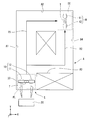
- FIG. 1 is a diagram of the transport system according to the present embodiment as viewed from above.
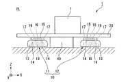
- FIG. 2 is a diagram showing a part of a procedure for carrying a product in the carrying system of the present embodiment.
- FIG. 3 is a diagram showing another part of the procedure for carrying the carried object in the carrying system of the present embodiment.
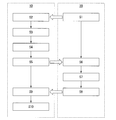
- FIG. 4 is a flow chart showing a procedure for carrying an object to be carried in the carrying system of the present embodiment.
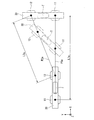
- FIG. 5 is a diagram showing an example of a method of moving a plurality of transport vehicles when changing the direction of a transport object in the transport system of the present embodiment.
- FIG. 6 is a diagram showing another example of a method of moving a plurality of transport vehicles when changing the direction of a transport object in the transport system of the present embodiment.
- FIG. 1 is a diagram of the transport system according to the present embodiment as viewed from above.
- FIG. 2 is a diagram showing a part of a procedure for carrying a product in the carrying system of the present embodiment.
- FIG. 7 is a figure which shows a part of procedure which conveys a conveyed article in another example of the conveyance system of this embodiment.
- FIG. 8 is a figure which shows another part of the procedure which conveys a conveyed article in another example of the conveyance system of this embodiment.
- the Z-axis direction shown in each figure is the vertical direction.
- the positive side in the Z-axis direction is the upper side in the vertical direction.
- the negative side in the Z-axis direction is the lower side in the vertical direction.
- the X-axis direction and the Y-axis direction shown in each drawing are horizontal directions orthogonal to the vertical direction, and are directions orthogonal to each other.
- the Z-axis direction which is the vertical direction is referred to as “vertical direction Z”.
- the upper side in the vertical direction is simply referred to as “upper side”
- the lower side in the vertical direction is simply referred to as “lower side”.
- the X-axis direction of the horizontal direction is referred to as “first horizontal direction X”
- the Y-axis direction of the horizontal direction is referred to as “second horizontal direction Y”.
- the workplace A has passages A1, A2, A3, A4.
- the passage A1 extends from the current position PL to one side (+Y side) of the second horizontal direction Y.
- the passage A2 extends from one end of the passage A1 on one side in the second horizontal direction Y to one side (+X side) in the first horizontal direction X.
- the passage A3 extends from the middle of the passage A1 to one side in the first horizontal direction X.
- the passage A4 extends from one end of the passage A3 on one side of the first horizontal direction X to one side of the second horizontal direction Y.
- One end of the passage A4 on one side in the second horizontal direction Y is connected to one end of the passage A2 on one side in the first horizontal direction X.
- the place where the passage A2 and the passage A4 are connected is the destination DE.
- the transfer system 1 of the present embodiment includes a plurality of transfer vehicles 10, a plate member 30, and a transfer control unit 20.
- the transport controller 20 controls the plurality of transport vehicles 10 to transport the transport object T.
- the transport control unit 20 is provided separately from the plurality of transport vehicles 10.
- the plurality of transport vehicles 10 are unmanned transport vehicles that transport the transport object T in cooperation.
- the plurality of transport vehicles 10 cooperate to hold and transport the transported object T.
- two carrier vehicles 10, a carrier vehicle 11 and a carrier vehicle 12 are provided.
- the transport vehicle 11 and the transport vehicle 12 have the same structure.
- each of the plurality of transport vehicles 10 includes a vehicle body 13, a plurality of wheels 14, a motor 17, a battery 18, a loading platform 15, an elevating device 19, and a load measuring unit 16.
- the plurality of wheels 14 are attached to the vehicle body 13.
- the plurality of wheels 14 are wheels that are rotatable in a plurality of horizontal directions, for example. Therefore, the carrier 10 of the present embodiment can move in a plurality of horizontal directions without changing the direction.
- the carrier 10 can move in each of the first horizontal direction X and the second horizontal direction Y without changing its direction.
- the motor 17 is arranged inside the vehicle body 13.
- the motor 17 drives the wheels 14.
- the motor 17 is provided for each wheel 14.
- the battery 18 is arranged inside the vehicle body 13.
- the battery 18 supplies electric power to the motor 17.
- the battery 18 supplies electric power to the plurality of motors 17.
- the battery 18 may be provided for each motor 17.
- the loading platform 15 is located above the vehicle body 13.
- the articles T are loaded on the loading platform 15.
- the articles T are loaded on the loading platform 15 of the present embodiment via the plate member 30. That is, in the present embodiment, the plurality of transport vehicles 10 transport the transport objects T stacked on the plate member 30.
- the lifting device 19 is arranged inside the vehicle body 13. As shown in FIGS. 2 and 3, the lifting device 19 moves the platform 15 in the vertical direction Z.
- the load measuring unit 16 is arranged inside the platform 15.
- the load measuring unit 16 measures the load applied from the transported object T to the transport vehicle 10.
- the “load applied from the transported object to the transportation vehicle” includes the load applied to the transportation vehicle from the transportation object and the other member when the transportation object is transported through another member.
- the load measuring unit 16 measures the load applied from the conveyed product T loaded on the loading platform 15 and the plate member 30 as another member.
- the load measuring unit 16 is not particularly limited as long as it can measure the load applied to the transport vehicle 10.
- the load measuring unit 16 may be, for example, a uniaxial force sensor or a 6-axis force sensor.
- the load measuring unit 16 detects a force, a moment, or the like applied to the transport vehicle 10 in addition to the load applied to the transport vehicle 10 from the transport object T. Good.
- the plate member 30 is a plate-shaped member whose plate surface faces the vertical direction Z.
- the material of the plate member 30 is not particularly limited.
- the plate member 30 extends in one of the horizontal directions. 1 to 3, the plate member 30 extends in the first horizontal direction X, for example.
- the plate member 30 has a rectangular shape when viewed in the vertical direction Z.
- the direction in which the plate member 30 extends is referred to as the “longitudinal direction”.
- the plate member 30 is supported from below by the plurality of transport vehicles 10.
- the plate member 30 is supported from below by the loading platform 15 of the transport vehicle 11 and the loading platform 15 of the transport vehicle 12.
- the transport control unit 20 controls the speed and the like of each transport vehicle 10 when moving each transport vehicle 10, and holds the relative position and relative attitude between each transport vehicle 10 and the plate member 30.
- the plate member 30 is arranged on the stand 40 and is supported by the stand 40 from below in a state where the plate member 30 is not supported by the carrier 10.
- the table 40 is, for example, arranged at each of the present location PL and the destination DE.
- the horizontal dimension of the table 40 is smaller than the longitudinal dimension of the plate member 30.
- the dimension in the vertical direction Z of the table 40 is larger than the dimension in the vertical direction Z of the transport vehicle 10 when the loading platform 15 is at the lowermost position, and the vertical direction of the transport vehicle 10 when the loading platform 15 is at the uppermost position. It is smaller than the Z dimension.
- the plate member 30 projects to both sides in the longitudinal direction of the mounting table 40 in a state of being arranged on the mounting table 40.
- Step S ⁇ b>1 is a step in which the transport control unit 20 transmits a loading instruction to each transport vehicle 10. Specifically, in step S ⁇ b>1, the transfer control unit 20 transmits to each transfer vehicle 10 an instruction to load the transfer objects T on the loading platform 15.
- Step S2 is a step in which each of the transport vehicles 10 receives a stacking instruction from the transport control unit 20.
- Step S3 is a step in which each of the transport vehicles 10 that receives the loading instruction loads the transport material T in cooperation with other transport vehicles 10.
- the transport vehicle 10 moves to the lower side of the plate member 30 arranged on the table 40 at the current position PL, as shown in FIG.
- the transported articles T are stacked on the plate member 30.
- the transport vehicle 11 and the transport vehicle 12 move below the plate member 30 and to positions where the mounting table 40 is sandwiched in the longitudinal direction.
- the loading device 15 is moved upward by the lifting device 19 and the plate member 30 is lifted together with the transported object T.
- each transport vehicle 10 can load the transported articles T on the plurality of loading platforms 15 via the plate member 30.
- Step S4 is a step in which each transport vehicle 10 measures the load applied from the transport object T by the load measuring unit 16.
- the transported object T is arranged on the plate member 30 with one longitudinal side displaced from the longitudinal center of the plate member 30, the transported object T is added to each transport vehicle 10.
- the applied loads may differ from each other.
- the load M2 applied to the transport vehicle 12 from the transport object T is larger than the load M1 applied to the transport vehicle 11 from the transport object T.
- Step S5 is a step in which each carrier 10 transmits the measurement result of the load measuring unit 16 and the current location to the carrier control unit 20.
- the current location transmitted from the transport vehicle 10 to the transport control unit 20 in step S5 is the position of the transport vehicle 10 when the transport objects T are loaded in step S4.
- Step S6 is a step in which the transport control unit 20 receives the measurement result of the load measuring unit 16 and the current location from each transport vehicle 10.
- Step S7 is a step in which the transport control unit 20 selects a moving route of each transport vehicle 10.
- the transportation control unit 20 extracts a transportation route for transporting the transported material T from the current location PL to the destination DE in the work area A.
- the method of extracting the transport route is not particularly limited. In the present embodiment, the transport control unit 20 extracts the transport route using, for example, the A * algorithm.
- the transport control unit 20 extracts, for example, the two transport routes R1 and R2 shown in FIG. 1 as the transport routes.
- the transport route R1 is a route for transporting the transport object T from the current position PL to the destination DE through the passages A1 and A2.
- the transport route R1 is a route for transporting the transport object T from the present location PL to the destination DE through the passage A1, the passage A3, and the passage A4.
- the transport control unit 20 extracts a moving route of each transport vehicle 10 when transporting the transported object T along each of the transport routes R1 and R2.
- the method of extracting the movement route is not particularly limited.
- the transport control unit 20 extracts the moving route using, for example, the A * algorithm.
- the “conveyance route” is a selection pattern of the passage through which the conveyed product T is conveyed
- the “movement route” is the conveyance when the conveyed product T is conveyed from the current position PL to the destination DE. This is the traveling locus of the vehicle 10.
- each transport vehicle 10 may be a plurality of moving routes of each transport vehicle 10.
- each of the transportation vehicles 10 travels in the first horizontal direction X without turning and bends, and as shown in FIGS. It is possible that the transport vehicle 10 turns and turns. In these cases, the moving route of the transport vehicle 10 in the transport route R2 is different.
- each transport vehicle 10 turns and turns
- the movement route of each transport vehicle 10 may differ depending on the way of turning. Specifically, when each transport vehicle 10 turns from the second horizontal direction Y to the first horizontal direction X and bends, the vehicle bends as shown in FIG. 5, and the bends as shown in FIG. Conceivable.
- the movement path P1a is a path that goes straight in a direction parallel to the first horizontal direction X.
- the movement path P2a is a path that goes straight in a direction that is obliquely inclined to one side (+Y side) of the second horizontal direction Y with respect to the first horizontal direction X.
- Each of the transport vehicles 11 and 12 changes its direction by rotating in the counterclockwise direction as viewed from above while traveling straight along each of the moving paths P1a and P2a.
- the plate member 30 and the conveyed product T rotate counterclockwise when viewed from above.
- the movement path P1b is a path that goes straight in a direction that is obliquely inclined to one side (+Y side) of the second horizontal direction Y with respect to the first horizontal direction X.
- the movement path P2b is a path that goes straight in a direction parallel to the first horizontal direction X.
- Each of the transport vehicles 11 and 12 changes its direction by rotating in a clockwise direction when viewed from above while traveling straight along each of the moving paths P1b and P2b.
- the plate member 30 and the conveyed product T rotate clockwise when viewed from above.
- the moving path P1a of the transport vehicle 11 when turning as shown in FIG. 5 and the moving path P1b of the transport vehicle 11 when turning as shown in FIG. 6 are different from each other.
- the moving path P2a of the transport vehicle 12 when turning as shown in FIG. 5 and the moving path P2b of the transport vehicle 12 when turning as shown in FIG. 6 are different from each other.
- the transport control unit 20 holds the relative position and the relative posture between each transport vehicle 10 and the plate member 30 when moving each transport vehicle 10. Therefore, when each transport vehicle 10 changes its direction and bends, the orientation of the transported object T and the orientation of the plate member 30 also change according to the orientation of the transport vehicle 10. On the other hand, when each transport vehicle 10 bends without changing its orientation, the orientation of the transported object T and the orientation of the plate member 30 do not change.
- the transport control unit 20 extracts all possible travel routes of the transport vehicles 10 for each of the transport routes R1 and R2.
- the transportation control unit 20 extracts the moving route in consideration of the direction of the transported material T at the destination DE. For example, when the transport object T is transported along the transport route R1 to the destination DE, if the transport vehicle 10 travels in the first horizontal direction X without changing the direction of the transport vehicle 10 when the transport vehicle 10 bends from the route A1 to the route A2, It is also possible to transport the transported article T to the destination DE without changing the direction of each transport vehicle 10. However, as shown by the chain double-dashed line in FIG.
- the transport control unit 20 does not extract the moving route for transporting the transport object T without changing the direction of the transport vehicle 10 even once.
- the first horizontal direction X in which the conveyed product T faces after being bent is opposite due to the difference in the way of bending. Therefore, for example, even if the conveyance route R1 is bent as shown in FIG. 5, the direction of the conveyed product T in the first horizontal direction X is the direction of the conveyed product T in the first horizontal direction X indicated by a two-dot chain line in FIG. And the opposite. Therefore, the transport control unit 20 does not, for example, extract a moving route that bends as shown in FIG. 5 in the transport route R1.
- the transport control unit 20 extracts a plurality of transport vehicles 10 after extracting all the moving routes of the transport vehicles 10 capable of transporting the transport object T from the current position PL to the destination DE in a predetermined posture.
- the total amount of energy consumed when the vehicle is moved along each of the movement paths is estimated.
- the transport control unit 20 estimates the total energy consumed based on the measurement result of the load measuring unit 16 and the distance traveled by the transport vehicle 10 from the current position PL to the destination DE.
- the transport control unit 20 considers that the value obtained by multiplying the measurement result of the load measuring unit 16 of the transport vehicle 10 by the distance of the travel route corresponds to the consumed energy, and is consumed by the plurality of transport vehicles 10 for each travel route. Estimate the total energy of
- the total energy E1 consumed by the transport vehicles 11 and 12 when turning as shown in FIG. 5 is expressed by the following formula 1, and is consumed by the transport vehicles 11 and 12 when turning as shown in FIG.
- the total energy E2 of the energy is expressed by the following equation 2.
- M1 is the load applied to the carrier 11 measured by the load measuring unit 16 of the carrier 11.
- M2 is the load applied to the transport vehicle 12 measured by the load measuring unit 16 of the transport vehicle 12.
- L1a is a travel distance on the travel route P1a.
- L2a is a travel distance on the travel route P2a.
- L1b is a travel distance on the travel route P1b.
- L2b is a travel distance on the travel route P2b.
- the transport control unit 20 calculates and estimates the total energy consumed by the transport vehicle 10 in the entire travel route as in the above Equations 1 and 2.
- the transport control unit 20 selects a travel route of the plurality of transport vehicles 10 based on the estimated sum of energy. In the present embodiment, the transport control unit 20 selects a movement route having the smallest estimated sum of energy from the extracted movement routes.
- the transport control unit 20 when there is a large deviation in the load applied from the transport object T to each of the transport vehicles 10, the travel route having the smallest traveling distance of the transport vehicle 10 having the greater load applied from the transport object T is selected. By doing so, the total amount of energy consumed tends to be the smallest. Therefore, the transport control unit 20 often selects a travel route that minimizes the travel distance of the transport vehicle 10 having a larger load applied from the transport object T.
- the transport control unit 20 does not estimate the total energy consumed, One extracted movement route is selected.
- Step S8 is a step in which the transport control unit 20 transmits the selected travel route to each transport vehicle 10.
- Step S9 is a step in which each of the transport vehicles 10 receives the movement route from the transport control unit 20.
- Step S10 is a step in which each carrier 10 moves to the destination along the received movement route.
- the plurality of transport vehicles 10 can transport the transported product T to the destination DE.
- the plurality of carrier vehicles 10 arrange the plate member 30 and the conveyed object T on the table 40 arranged in the destination DE.
- each transport vehicle 10 is transported.
- the energy consumed in the entire delivery system 1 is not always the smallest. This is because even if the load applied to each carrier vehicle 10 is significantly different, even if the traveling distance of the carrier vehicle 10 with the smaller applied load is increased to increase the total traveling distance of the plurality of carrier vehicles 10, This is because there is a case where the energy consumed as a whole becomes smaller when the traveling distance of the carrier vehicle 10 having a larger load is reduced as much as possible. As a result, the transfer efficiency of the entire transfer system 1 may not be sufficiently improved.
- "conveyance efficiency" includes energy efficiency, time efficiency, cost efficiency, etc. at the time of conveying a conveyed product to a destination.
- the transport control unit 20 transports the transport object T from the current location PL to the predetermined destination DE
- the transport routes of the multiple transport vehicles 10 are multiple
- the moving routes of the plurality of transport vehicles 10 are selected. Therefore, even when the loads applied to the transport vehicles 10 from the transport object T are different, it is necessary to consider the difference in the applied loads and to select a moving route in which the energy consumed by the entire transport system 1 is small. Easy to choose. Therefore, the energy consumed when the transported object T is transported can be reduced, and the transport efficiency of the overall transport system 1 can be improved.
- the transfer control unit 20 measures the load measuring unit 16 when there are a plurality of movement routes of the plurality of transfer vehicles 10 when the transfer object T is transferred from the current position PL to the destination DE. Based on the result and the distance traveled by the transport vehicle 10 from the current position PL to the destination DE, the travel route of the plurality of transport vehicles 10 is selected. Therefore, in consideration of the difference in the load applied to each carrier 10 and the difference in the distance traveled by each carrier 10, it is easy to more appropriately select a travel route in which the energy consumed in the entire transport system 1 is small. .. Therefore, the energy consumed when the transported object T is transported can be further reduced, and the transport efficiency of the overall transport system 1 can be improved.
- the transport control unit 20 determines that the plurality of transport vehicles 10 are in the current location based on the measurement result of the load measuring unit 16 and the distance traveled by the transport vehicle 10 from the current location PL to the destination DE. Estimate the sum of the energy consumed during the journey from PL to the destination DE. Then, the transport control unit 20 selects the travel route of the plurality of transport vehicles 10 based on the estimated sum of energy. Therefore, it is easier to more appropriately select the movement route in which the energy consumed in the entire transport system 1 is small, and the energy consumed when the transport object T is transported can be further reduced. Thereby, the transportation efficiency of the entire transportation system 1 can be further improved.
- the transport control unit 20 selects the travel route having the smallest estimated total energy. Therefore, it is easy to minimize the energy consumed in the entire transport system 1, and it is easy to optimize the energy efficiency of the entire transport system 1. Thereby, the transportation efficiency of the entire transportation system 1 can be further improved.
- the present invention is not limited to the above-mentioned embodiment, and the following other configurations and methods can be adopted.
- the transport control unit 20 is not particularly limited as long as it selects each of the moving routes of the plurality of transport vehicles 10 based on the measurement result of the load measuring unit 16.
- the estimation of the total energy by the transport control unit 20 may be performed using a table stored in the transport control unit 20 in advance.
- the table stores the estimated value of the total energy with respect to the load applied to the transport vehicle 10 and the travel distance of the transport vehicle 10.
- the transfer control unit 20 may consider the energy required to rotate the transfer vehicle 10 when estimating the energy consumed in the transfer vehicle 10.
- the conveyance control unit 20 determines the value obtained by multiplying the measurement result of the load measuring unit 16 of the conveyance vehicle 10 by the distance of the movement path and the inertia of the conveyance vehicle 10 in the state where the load is applied to the rotation angle of the conveyance vehicle 10. It may be considered that the sum of the value multiplied by and the energy consumed. In this case, the energy consumed in each carrier 10 can be estimated more accurately.
- the energy required for rotation is sufficiently smaller than the energy required for movement. Therefore, even when the energy required for rotation is not taken into consideration as in the above-described embodiment, the transport control unit 20 can sufficiently accurately estimate the energy consumed in the transport vehicle 10.
- the transport control unit 20 may select the travel route without estimating the total energy consumed until the plurality of transport vehicles 10 move from the current position PL to the destination DE.
- the transport control unit 20 may select the travel route of the plurality of transport vehicles 10 without being based on the distance traveled by the transport vehicle 10 from the current position PL to the destination DE.
- the transport control unit 20 may select the travel route of the plurality of transport vehicles 10 based on the remaining power of the batteries 18 in the plurality of transport vehicles 10. According to this configuration, for example, when the remaining amount of power of the batteries 18 in the plurality of transport vehicles 10 is uneven, the travel distance of the transport vehicle 10 in which the remaining power of the batteries 18 is small can be shortened. As a result, it is possible to prevent the batteries of only some of the plurality of transport vehicles 10 from running out, and improve the transport efficiency of the transport system. In this case as well, the transport control unit 20 may estimate the total energy consumed and select the travel route based on the estimated total energy. The transport control unit 20 may select the travel route by giving priority to the total sum of energy consumed, or may select the travel route by giving priority to the remaining power of the battery 18.
- the transfer control unit 20 may change the relative position of the transfer vehicle 10 and the plate member 30 in the longitudinal direction based on the measurement result of the load measuring unit 16. With this configuration, it is possible to change the relative distance between the transport object T loaded on the plate member 30 and the transport vehicle 10, and it is possible to change the load applied to each transport vehicle 10. Therefore, for example, by reducing the load applied to the transport vehicle 10 that tends to increase the travel distance, it is easy to reduce the energy consumption of the entire transport system and improve the transport efficiency of the overall transport system.
- a method of changing the relative position of the transport vehicle 10 and the plate member 30 in the longitudinal direction as shown in FIG. 7, after the plate member 30 and the transported object T are returned to the mounting table 40, the transport vehicle 10 is moved to the longitudinal direction. It is possible to adopt a method in which the position in the direction is changed, and as shown in FIG. 8, the transported object T and the plate member 30 are loaded again on the transportation vehicle 10.
- the transport control unit 20 sets the load applied from the transport object T to the same position in each of the plurality of transport vehicles 10.
- the relative position of the plate member 30 in the longitudinal direction may be changed. According to this configuration, it is possible to make the energy consumption of each transport vehicle 10 the same when traveling the same travel distance. Therefore, it is easy to minimize the energy consumption of the entire transport system by simply selecting the travel route that minimizes the total travel distance of the plurality of transport vehicles 10. That is, when the load applied to each of the transport vehicles 10 measured by the load measuring unit 16 is the same, the transport control unit 20 determines the travel route of each of the transport vehicles 10 that minimizes the sum of the travel distances of the plurality of transport vehicles 10. May be selected. Thereby, the transfer efficiency of the entire transfer system can be improved.
- the transport control unit 20 lowers the loading platform 15 by the elevating device 19, and again the plate member 30 and the transported product T. And are placed on the table 40.
- the transport control unit 20 moves the transport vehicle 12 in the longitudinal direction away from the transport object T (+X direction) as shown in FIG. 7. To move.
- the transport control unit 20 raises the loading platform 15 by the lifting device 19 and reloads the transport object T and the plate member 30 on the plurality of transport vehicles 10.
- the transport control unit 20 changes the relative positions of the transport vehicle 10 and the plate member 30 in this way, and makes the loads applied to the transport vehicles 10 the same.
- one of the transport vehicles 10 serves as a leader machine and follows the instruction of the transport control unit 20, and the rest serves as follower machines and follows the movement of the leader machine. But it's okay.
- the carrier vehicle 10 that has become the leader machine sequentially transmits information on the current position and posture to the carrier vehicle 10 that has become the follower machine, and the carrier vehicle 10 that has become the follower machine is based on that information. Control your position and attitude. Further, the carrier vehicle 10 that has become the leader machine may select its own travel route and the travel route of the carrier vehicle 10 that has become the follower machine based on an instruction from the transport control unit 20.
- the transfer control unit 20 may be provided in at least one of the plurality of transfer vehicles 10.
- the transport control unit 20 transports the transport object T by making the transport vehicle 10 including the transport control unit 20 cooperate with another transport vehicle 10 different from the transport vehicle 10 including the transport control unit 20.
- the transport control unit 20 causes the transport vehicle 10 to perform self-transportation. Based on the measurement result of the load measuring unit 16 included in and the measurement result of the load measuring unit 16 included in the other transport vehicle 10, the moving route of the other transport vehicle 10 is selected.
- the transport control unit 20 controls the load measuring unit included in the transport vehicle 10 itself. It selects its own movement route based on the 16 measurement results. As a result, like the above-described embodiment, the energy consumption of the entire transfer system can be reduced, and the transfer efficiency of the entire transfer system can be improved.
- the transport vehicle 10 including the transport control unit 20 may select the travel route of another transport vehicle 10, and does not have to select its own travel route. Good.
- the travel route of the transport vehicle 10 itself including the transport control unit 20 may be selected by the transport control unit 20 provided in another transport vehicle 10 or the like.
- each carrier vehicle 10 may be separately controlled by the leader machine and the follower machine.
- the transport control unit 20 of each transport vehicle 10 calculates the travel route of each of the transport vehicles 10.
- the movement route of each transport vehicle 10 calculates a result which is estimated to be the most correct computation result based on each computation result. It may be selected by the transport control unit 20. In this way, when the calculation results vary, it may be easier to select the most suitable travel route by selecting the travel route by the transport control unit 20 provided in another transport vehicle 10. Therefore, it is easy to further reduce the energy consumption of the entire transfer system and improve the transfer efficiency of the entire transfer system.
- the predetermined destination DE is the final destination for transporting the transport object T, but the present invention is not limited to this.
- the transport control unit 20 may determine one or more provisional destinations up to the destination DE and select a travel route using each provisional destination as a predetermined destination.
- the transport control unit 20 may grasp the position of the obstacle or the like. In this case, the transport control unit 20 selects a travel route that avoids an obstacle or the like for each of the transport vehicles 10.
- the transport vehicle 10 is not particularly limited as long as it can transport the transport object T in cooperation with other transport vehicles 10.
- the plate member 30 may be fixed to the transport vehicle 10 by a fastener or the like.
- the transport vehicle 10 may load the transport objects T on the loading platform 15 without using the plate member 30.
- the transport vehicle 10 may have, for example, a hand that grips the transport object T.
- the objects T may be gripped and carried by the hands of the plurality of carrier vehicles 10.
- the load measuring unit 16 may measure the load applied to the transport vehicle 10 by a suspension method.
- the wheels 14 of the transport vehicle 10 may be wheels that can move only in one of the horizontal directions.
- the structures of the plurality of transport vehicles 10 may be different from each other.
- the carrier vehicle 10 may be a manned carrier vehicle as long as it is controlled by the carrier control unit 20.
- the number of transport vehicles 10 included in the transport system is not particularly limited as long as it is two or more.
- a plurality of transport vehicles cooperate to transport a transport object means that the transport article T is cooperatively held and transported by the plurality of transport vehicles 10 as in the above-described embodiment.
- the plurality of transport vehicles 10 may transport the plurality of transport objects T by transporting one or more different transport objects T, respectively.
- each of the plurality of transport vehicles 10 transports one or more different transport objects T, for example, when the plurality of transport vehicles 10 transport the transport objects T to the same destination DE through different transport routes, It is possible to shorten the time required to convey the plurality of conveyed articles T.
- the transport distance of the transport vehicle 10 that transports the heavy transport object T becomes relatively short. It is possible to move the transporting route having a relatively long travel distance to the transporting vehicle 10 that transports the light transporting object T by moving the route. Thereby, the energy consumption of the entire transfer system can be reduced, and the transfer efficiency of the entire transfer system can be improved.
- the environment in which the transport system of the above-described embodiment is used is not particularly limited.
- the transported object T transported by the transportation system is not particularly limited.
- the configurations described in the present specification can be appropriately combined within a range not inconsistent with each other.
Landscapes
- Engineering & Computer Science (AREA)
- General Physics & Mathematics (AREA)
- Physics & Mathematics (AREA)
- Mechanical Engineering (AREA)
- Power Engineering (AREA)
- Transportation (AREA)
- Aviation & Aerospace Engineering (AREA)
- Radar, Positioning & Navigation (AREA)
- Remote Sensing (AREA)
- Automation & Control Theory (AREA)
- Sustainable Energy (AREA)
- Sustainable Development (AREA)
- Life Sciences & Earth Sciences (AREA)
- Control Of Position, Course, Altitude, Or Attitude Of Moving Bodies (AREA)
Abstract
本発明の搬送システムの一つの態様は、搬送物を協調して搬送する複数の搬送車と、複数の搬送車を制御して、搬送物を搬送させる搬送制御部と、を備える。複数の搬送車のそれぞれは、搬送物から加えられる荷重を測定する荷重測定部を有する。搬送制御部は、搬送物を現在地から所定の目的地に搬送する際に複数の搬送車の移動経路が複数存在する場合、荷重測定部の測定結果に基づいて複数の搬送車の移動経路をそれぞれ選択する。
Description
本発明は、搬送システム、および搬送車に関する。
搬送車による搬送システムが知られている。例えば、日本国公開公報特開2012-113429号公報には、積込作業の作業性を高めることを目的として走行経路上の経由点を選択する無人車両の走行システムが記載されている。
搬送システムとしては、複数の搬送車を協調させて搬送物を搬送する搬送システムが考えられる。この場合、1台の搬送車において経路選択を行う場合と同様にして複数の搬送車の経路選択を行うと、搬送システム全体の搬送効率を十分に向上できない場合があった。
本発明は、上記事情に鑑みて、複数の搬送車によって搬送物を協調して搬送する際の搬送効率を向上できる搬送システムおよび搬送車を提供することを目的の一つとする。
本発明の搬送システムの一つの態様は、搬送物を協調して搬送する複数の搬送車と、前記複数の搬送車を制御して、前記搬送物を搬送させる搬送制御部と、を備える。前記複数の搬送車のそれぞれは、前記搬送物から加えられる荷重を測定する荷重測定部を有する。前記搬送制御部は、前記搬送物を現在地から所定の目的地に搬送する際に前記複数の搬送車の移動経路が複数存在する場合、前記荷重測定部の測定結果に基づいて前記複数の搬送車の前記移動経路をそれぞれ選択する。
本発明の搬送車の一つの態様は、他の搬送車と協調して搬送物を搬送させる搬送制御部と、前記搬送物から加えられる荷重を測定する荷重測定部と、を備える。本発明の搬送車の一つの態様は、前記搬送物を現在地から所定の目的地に搬送する際に前記他の搬送車の移動経路が複数存在する場合、前記搬送制御部によって、自らが備える前記荷重測定部の測定結果と前記他の搬送車に備えられる前記荷重測定部の測定結果とに基づいて前記他の搬送車の前記移動経路を選択する。
本発明の一つの態様によれば、複数の搬送車によって搬送物を協調して搬送する際の搬送効率を向上できる。
各図に適宜示すZ軸方向は、鉛直方向である。Z軸方向の正の側は、鉛直方向上側である。Z軸方向の負の側は、鉛直方向下側である。各図に適宜示すX軸方向およびY軸方向は、鉛直方向と直交する水平方向であり、互いに直交する方向である。以下の説明においては、鉛直方向であるZ軸方向を「鉛直方向Z」と呼ぶ。また、鉛直方向上側を単に「上側」と呼び、鉛直方向下側を単に「下側」と呼ぶ。また、水平方向のうちのX軸方向を「第1水平方向X」と呼び、水平方向のうちのY軸方向を「第2水平方向Y」と呼ぶ。
以下の実施形態においては、図1に示す作業場A内において現在地PLから所定の目的地DEまで、搬送システム1によって搬送物Tを搬送する例について説明する。図1に示すように、作業場Aは、通路A1,A2,A3,A4を有する。通路A1は、現在地PLから第2水平方向Yの一方側(+Y側)に延びている。通路A2は、通路A1のうち第2水平方向Yの一方側の端部から第1水平方向Xの一方側(+X側)に延びている。通路A3は、通路A1の途中から第1水平方向Xの一方側に延びている。通路A4は、通路A3のうち第1水平方向Xの一方側の端部から第2水平方向Yの一方側に延びている。通路A4のうち第2水平方向Yの一方側の端部は、通路A2のうち第1水平方向Xの一方側の端部と繋がっている。通路A2と通路A4とが繋がる箇所が、目的地DEである。
本実施形態の搬送システム1は、複数の搬送車10と、板部材30と、搬送制御部20と、を備える。搬送制御部20は、複数の搬送車10を制御して、搬送物Tを搬送させる。本実施形態において搬送制御部20は、複数の搬送車10と別に設けられている。複数の搬送車10は、搬送物Tを協調して搬送する無人搬送車である。本実施形態において複数の搬送車10は、搬送物Tを協力して保持し、搬送する。本実施形態において搬送車10は、搬送車11と搬送車12との2台設けられている。本実施形態において搬送車11と搬送車12とは、互いに同様の構造である。
図2に示すように、複数の搬送車10のそれぞれは、車体13と、複数の車輪14と、モータ17と、バッテリ18と、荷台15と、昇降装置19と、荷重測定部16と、を有する。複数の車輪14は、車体13に取り付けられている。複数の車輪14は、例えば、水平方向のうちの複数の方向に回転可能な車輪である。そのため、本実施形態の搬送車10は、向きを変えずに複数の水平方向に移動できる。搬送車10は、例えば、向きを変えずに第1水平方向Xおよび第2水平方向Yのそれぞれに移動できる。
モータ17は、車体13の内部に配置されている。モータ17は、車輪14を駆動する。本実施形態においてモータ17は、車輪14ごとに設けられている。バッテリ18は、車体13の内部に配置されている。バッテリ18は、モータ17に電力を供給する。本実施形態においてバッテリ18は、複数のモータ17に電力を供給する。なお、バッテリ18は、モータ17ごとに設けられていてもよい。
荷台15は、車体13の上側に位置する。荷台15には、搬送物Tが積載される。本実施形態の荷台15には、板部材30を介して搬送物Tが積載される。すなわち、本実施形態において複数の搬送車10は、板部材30上に積載された搬送物Tを搬送する。昇降装置19は、車体13の内部に配置されている。図2および図3に示すように、昇降装置19は、荷台15を鉛直方向Zに移動させる。
本実施形態において荷重測定部16は、荷台15の内部に配置されている。荷重測定部16は、搬送物Tから搬送車10に加えられる荷重を測定する。本明細書において「搬送物から搬送車に加えられる荷重」とは、搬送物を他の部材を介して搬送する場合には、搬送物および他の部材から搬送車に加えられる荷重を含む。本実施形態において荷重測定部16は、荷台15に積載された搬送物Tおよび他の部材としての板部材30から加えられる荷重を測定する。
荷重測定部16は、搬送車10に加えられる荷重を測定できるならば、特に限定されない。荷重測定部16は、例えば、1軸の力覚センサであってもよいし、6軸の力覚センサであってもよい。荷重測定部16が6軸の力覚センサである場合、荷重測定部16は、搬送物Tから搬送車10に加えられる荷重以外に、搬送車10に加えられる力およびモーメント等を検出してもよい。
板部材30は、板面が鉛直方向Zを向く板状の部材である。板部材30の材料は、特に限定されない。板部材30は、水平方向のうちの一方向に延びている。図1から図3において板部材30は、例えば、第1水平方向Xに延びている。図1に示すように、板部材30は、鉛直方向Zに沿って視て、長方形状である。以下の説明においては、板部材30が延びる方向を「長手方向」と呼ぶ。
図3に示すように、板部材30は、複数の搬送車10によって下側から支持される。本実施形態において板部材30は、搬送車11の荷台15と搬送車12の荷台15とによって下側から支持される。板部材30を介することで、複数の搬送車10によって搬送物Tを協力して保持することが容易であり、搬送物Tを搬送しやすい。本実施形態において板部材30は、複数の搬送車10によって下側から支持された状態において搬送車10に固定されない。本実施形態において搬送制御部20は、各搬送車10を移動させる際、各搬送車10の速度等を制御して、各搬送車10と板部材30との相対位置および相対姿勢を保持する。
図2に示すように、板部材30は、搬送車10によって支持されない状態において、置台40上に配置され、置台40によって下側から支持されている。図示は省略するが、置台40は、例えば、現在地PLおよび目的地DEにそれぞれ配置されている。置台40の水平方向の寸法は、板部材30の長手方向の寸法よりも小さい。置台40の鉛直方向Zの寸法は、荷台15が最も下側に位置する状態における搬送車10の鉛直方向Zの寸法よりも大きく、荷台15が最も上側に位置する状態における搬送車10の鉛直方向Zの寸法よりも小さい。板部材30は、置台40上に配置された状態において、置台40よりも長手方向の両側に突出する。
本実施形態の搬送システム1は、図4に示すステップS1~S10に沿って、搬送物Tを現在地PLから目的地DEまで搬送する。ステップS1は、搬送制御部20が、各搬送車10に積載指示を送信するステップである。具体的に、ステップS1において搬送制御部20は、各搬送車10に対して、荷台15上に搬送物Tを積載する指示を送信する。ステップS2は、各搬送車10が、搬送制御部20から積載指示を受信するステップである。
ステップS3は、積載指示を受信した各搬送車10が、他の搬送車10と協調して搬送物Tを積載するステップである。ステップS3において搬送車10は、図2に示すように、現在地PLの置台40上に配置された板部材30の下側に移動する。このとき、板部材30上には、搬送物Tが積載されている。搬送車11と搬送車12とは、板部材30の下側で、かつ、置台40を長手方向に挟む位置にそれぞれ移動する。次に、図3に示すように、各搬送車10は、昇降装置19によって荷台15を上側に移動させ、板部材30を搬送物Tとともに持ち上げる。これにより、各搬送車10は、板部材30を介して搬送物Tを複数の荷台15上に積載できる。
ステップS4は、各搬送車10が、搬送物Tから加えられる荷重を荷重測定部16によって測定するステップである。図3に示すように、例えば搬送物Tが板部材30の長手方向の中央に対して長手方向一方側にずれて板部材30上に配置される場合、搬送物Tから各搬送車10に加えられる荷重は、互いに異なる場合がある。例えば、図3では、搬送物Tから搬送車12に加えられる荷重M2は、搬送物Tから搬送車11に加えられる荷重M1よりも大きい。
ステップS5は、各搬送車10が、荷重測定部16の測定結果および現在地を搬送制御部20に送信するステップである。ステップS5において搬送車10から搬送制御部20に送信する現在地とは、ステップS4において搬送物Tを積載した際の搬送車10の位置である。ステップS6は、搬送制御部20が、各搬送車10から荷重測定部16の測定結果および現在地を受信するステップである。
ステップS7は、搬送制御部20が、各搬送車10の移動経路を選択するステップである。まず、ステップS7において搬送制御部20は、作業場A内において搬送物Tを現在地PLから目的地DEまで搬送する搬送経路を抽出する。搬送経路を抽出する方法は、特に限定されない。本実施形態において搬送制御部20は、例えば、A*アルゴリズムを用いて搬送経路を抽出する。
搬送制御部20には、例えば、予め作業場A内の通路A1~A4の情報と、現在地PLおよび目的地DEの位置情報が記憶されている。搬送制御部20は、例えば、搬送経路として図1に示す2つの搬送経路R1,R2を抽出する。搬送経路R1は、現在地PLから通路A1および通路A2を通って目的地DEに搬送物Tを搬送する経路である。搬送経路R1は、現在地PLから通路A1、通路A3および通路A4を通って目的地DEに搬送物Tを搬送する経路である。
次に、搬送制御部20は、各搬送経路R1,R2に沿って搬送物Tを搬送する際の各搬送車10の移動経路を抽出する。移動経路を抽出する方法は、特に限定されない。本実施形態において搬送制御部20は、例えば、A*アルゴリズムを用いて移動経路を抽出する。なお、本明細書において「搬送経路」とは、搬送物Tが搬送される通路の選択パターンであり、「移動経路」とは、搬送物Tを現在地PLから目的地DEまで搬送する際における搬送車10の走行軌跡である。
ここで、同じ搬送経路に沿って搬送物Tを搬送する場合であっても、各搬送車10の移動経路は、複数存在する場合がある。例えば、搬送経路R2において通路A1から通路A3に曲がる際には、各搬送車10が向きを変えずに第1水平方向Xに走行して曲がる場合と、図5および図6に示すように各搬送車10が向きを変えて曲がる場合と、が考えられる。これらの場合には、それぞれ搬送経路R2内における搬送車10の移動経路が異なる。
各搬送車10が向きを変えて曲がる場合においても、曲がり方によって各搬送車10の移動経路が異なる場合がある。具体的には、各搬送車10が第2水平方向Yから第1水平方向Xに向きを変えて曲がる場合、図5に示すように曲がる場合と、図6に示すように曲がる場合と、が考えられる。
図5に示す場合、搬送車11が移動経路P1aに沿って移動し、搬送車12が移動経路P2aに沿って移動する。移動経路P1aは、第1水平方向Xと平行な方向に直進する経路である。移動経路P2aは、第1水平方向Xに対して第2水平方向Yの一方側(+Y側)に斜めに傾いた方向に直進する経路である。各搬送車11,12は、各移動経路P1a,P2aに沿って直進しつつ、上側から視て反時計回りに自転することで向きを変える。図5に示す曲がり方の場合、板部材30および搬送物Tは、上側から視て反時計回りに自転する。
図6に示す場合、搬送車11が移動経路P1bに沿って移動し、搬送車12が移動経路P2bに沿って移動する。移動経路P1bは、第1水平方向Xに対して第2水平方向Yの一方側(+Y側)に斜めに傾いた方向に直進する経路である。移動経路P2bは、第1水平方向Xと平行な方向に直進する経路である。各搬送車11,12は、各移動経路P1b,P2bに沿って直進しつつ、上側から視て時計回りに自転することで向きを変える。図6に示す曲がり方の場合、板部材30および搬送物Tは、上側から視て時計回りに自転する。
このように、図5に示すように曲がる場合の搬送車11の移動経路P1aと、図6に示すように曲がる場合の搬送車11の移動経路P1bとは、互いに異なる。図5に示すように曲がる場合の搬送車12の移動経路P2aと、図6に示すように曲がる場合の搬送車12の移動経路P2bとは、互いに異なる。
なお、上述したように、本実施形態において搬送制御部20は、各搬送車10を移動させる際、各搬送車10と板部材30との相対位置および相対姿勢を保持する。そのため、各搬送車10が向きを変えて曲がる場合、搬送物Tの向きおよび板部材30の向きも搬送車10の向きに合わせて変わる。一方、各搬送車10が向きを変えずに曲がる場合、搬送物Tの向きおよび板部材30の向きは変わらない。
搬送制御部20は、各搬送経路R1,R2ごとに、各搬送車10の移動経路として考えられる移動経路をすべて抽出する。本実施形態において搬送制御部20は、目的地DEにおける搬送物Tの向きを考慮して、移動経路の抽出を行う。例えば、搬送経路R1に沿って搬送物Tを目的地DEまで搬送する場合、通路A1から通路A2に曲がる際に各搬送車10の向きを変えずに第1水平方向Xに走行して曲がれば、各搬送車10の向きを変えることなく搬送物Tを目的地DEに搬送することも可能である。しかし、図1に二点鎖線で示すように、目的地DEにおいて搬送物Tの向きを、現在地PLにおける搬送物Tの向きと変える必要がある場合、少なくとも一度は各搬送車10の向きを変える必要がある。そのため、搬送制御部20は、搬送車10の向きを一度も変えずに搬送物Tを搬送する移動経路を抽出しない。
また、図5および図6に示すように、曲がり方の違いによって、曲がった後の搬送物Tが向く第1水平方向Xの向きが逆向きとなる。そのため、例えば、搬送経路R1において図5に示すように曲がっても、搬送物Tの第1水平方向Xの向きは、図1に二点鎖線で示す搬送物Tの第1水平方向Xの向きと逆向きとなる。したがって、搬送制御部20は、例えば、搬送経路R1において図5に示すように曲がる移動経路を抽出しない。
上述したようにして、搬送物Tを現在地PLから所定の姿勢で目的地DEまで搬送可能な各搬送車10の移動経路をすべて抽出した後、搬送制御部20は、複数の搬送車10を抽出した各移動経路に沿って移動させた場合に消費されるエネルギの総和を推定する。本実施形態において搬送制御部20は、荷重測定部16の測定結果と現在地PLから目的地DEまでに搬送車10が移動する距離とに基づいて、消費されるエネルギの総和を推定する。搬送制御部20は、搬送車10の荷重測定部16の測定結果に移動経路の距離を乗じた値を消費されるエネルギに相当するとみなして、移動経路ごとに、複数の搬送車10で消費されるエネルギの総和を推定する。
例えば、図5に示すように曲がる場合の搬送車11,12で消費されるエネルギの総和E1は以下の式1で表され、図6に示すように曲がる場合の搬送車11,12で消費されるエネルギの総和E2は以下の式2で表される。
E1=M1×L1a+M2×L2a …式1
E2=M1×L1b+M2×L2b …式2
E2=M1×L1b+M2×L2b …式2
M1は、搬送車11の荷重測定部16によって測定された搬送車11に加えられる荷重である。M2は、搬送車12の荷重測定部16によって測定された搬送車12に加えられる荷重である。L1aは、移動経路P1aにおける走行距離である。L2aは、移動経路P2aにおける走行距離である。L1bは、移動経路P1bにおける走行距離である。L2bは、移動経路P2bにおける走行距離である。
搬送制御部20は、上記の式1および式2のようにして、各移動経路の全体において搬送車10で消費されるエネルギの総和を算出し、推定する。搬送制御部20は、推定したエネルギの総和に基づいて複数の搬送車10の移動経路を選択する。本実施形態において搬送制御部20は、抽出した移動経路のうちから、推定したエネルギの総和が最も小さくなる移動経路を選択する。
なお、例えば、各搬送車10に搬送物Tから加えられる荷重に大きな偏りがある場合には、搬送物Tから加えられる荷重が大きい方の搬送車10の走行距離が最も小さくなる移動経路を選択することで、消費されるエネルギの総和が最も小さくなりやすい。そのため、搬送制御部20は、搬送物Tから加えられる荷重が大きい方の搬送車10の走行距離が最も小さくなる移動経路を選択する場合が多い。
また、例えば、上述したようにして移動経路を抽出した結果、各搬送車10の移動経路が1つしかない場合には、搬送制御部20は、消費されるエネルギの総和を推定することなく、抽出した1つの移動経路を選択する。
ステップS8は、搬送制御部20が、各搬送車10に選択した移動経路を送信するステップである。ステップS9は、各搬送車10が、搬送制御部20から移動経路を受信するステップである。ステップS10は、各搬送車10が、受信した移動経路に沿って目的地に移動するステップである。これにより、複数の搬送車10によって、搬送物Tを目的地DEに搬送することができる。目的地DEにおいて複数の搬送車10は、目的地DEに配置された置台40上に、板部材30および搬送物Tを配置する。
例えば、複数の搬送車10の走行距離の総和が最も小さくなる各搬送車10の移動経路を選択して、搬送物Tを現在地PLから目的地DEまで搬送する場合であっても、各搬送車10に搬送物Tから加えられる荷重がそれぞれ異なる場合には、搬送システム1全体で消費されるエネルギが最も小さくなるとは限らない。これは、各搬送車10に加えられる荷重が大きく異なる場合、加えられる荷重が小さい方の搬送車10の走行距離を大きくして複数の搬送車10の走行距離の総和を大きくしても、加えられる荷重が大きい方の搬送車10の走行距離を少しでも小さくした方が、全体で消費されるエネルギが小さくなる場合等が存在するためである。そのため、搬送システム1全体の搬送効率を十分に向上できない場合があった。なお、本明細書において「搬送効率」とは、搬送物を目的地まで搬送する際のエネルギ効率、時間効率、および費用効率等を含む。
これに対して、本実施形態によれば、搬送制御部20は、搬送物Tを現在地PLから所定の目的地DEに搬送する際に複数の搬送車10の移動経路が複数存在する場合、荷重測定部16の測定結果に基づいて複数の搬送車10の移動経路をそれぞれ選択する。そのため、各搬送車10に搬送物Tから加えられる荷重が異なっている場合であっても、加えられる荷重の差異を考慮して、搬送システム1全体で消費されるエネルギが小さくなる移動経路を適切に選択しやすい。したがって、搬送物Tを搬送する際に消費されるエネルギを低減でき、搬送システム1全体の搬送効率を向上できる。
また、本実施形態によれば、搬送制御部20は、搬送物Tを現在地PLから目的地DEに搬送する際に複数の搬送車10の移動経路が複数存在する場合、荷重測定部16の測定結果と現在地PLから目的地DEまでに搬送車10が移動する距離とに基づいて、複数の搬送車10の移動経路を選択する。そのため、各搬送車10に加えられる荷重の差異と各搬送車10が移動する距離の差異とを考慮して、搬送システム1全体で消費されるエネルギが小さくなる移動経路をより適切に選択しやすい。したがって、搬送物Tを搬送する際に消費されるエネルギをより低減でき、搬送システム1全体の搬送効率を向上できる。
また、本実施形態によれば、搬送制御部20は、荷重測定部16の測定結果と現在地PLから目的地DEまでに搬送車10が移動する距離とに基づいて、複数の搬送車10が現在地PLから目的地DEまで移動するまでの間に消費されるエネルギの総和を推定する。そして、搬送制御部20は、推定したエネルギの総和に基づいて複数の搬送車10の移動経路を選択する。そのため、搬送システム1全体で消費されるエネルギが小さくなる移動経路をより適切に選択しやすく、搬送物Tを搬送する際に消費されるエネルギをより低減できる。これにより、搬送システム1全体の搬送効率をより向上できる。
また、本実施形態によれば、搬送制御部20は、推定したエネルギの総和が最も小さくなる移動経路を選択する。そのため、搬送システム1全体で消費されるエネルギを最も小さくしやすく、搬送システム1全体のエネルギ効率を最適化しやすい。これにより、搬送システム1全体の搬送効率をより向上できる。
本発明は上述の実施形態に限られず、以下の他の構成および方法を採用することもできる。搬送制御部20は、荷重測定部16の測定結果に基づいて複数の搬送車10の移動経路をそれぞれ選択するならば、特に限定されない。搬送制御部20によるエネルギの総和の推定は、予め搬送制御部20に記憶されたテーブルを用いて行われてもよい。テーブルには、搬送車10に加えられる荷重および搬送車10の走行距離に対するエネルギの総和の推定値が格納されている。
搬送制御部20は、搬送車10において消費されるエネルギを推定する際に、搬送車10の回転に要するエネルギを考慮してもよい。この場合、搬送制御部20は、搬送車10の荷重測定部16の測定結果に移動経路の距離を乗じた値と、荷重が加えられた状態の搬送車10のイナーシャに搬送車10の回転角度を乗じた値と、の和を消費されるエネルギに相当するとみなしてもよい。この場合、より精度よく各搬送車10において消費されるエネルギを推定することができる。なお、回転に要するエネルギは、移動に要するエネルギよりも十分に小さい。そのため、上述した実施形態のように回転に要するエネルギを考慮しない場合であっても、搬送制御部20は、搬送車10において消費されるエネルギを十分に精度よく推定できる。
搬送制御部20は、複数の搬送車10が現在地PLから目的地DEまで移動するまでの間に消費されるエネルギの総和を推定せずに、移動経路を選択してもよい。搬送制御部20は、現在地PLから目的地DEまでに搬送車10が移動する距離に基づかずに、複数の搬送車10の移動経路を選択してもよい。
搬送制御部20は、複数の搬送車10におけるバッテリ18の電力残量に基づいて、複数の搬送車10の移動経路を選択してもよい。この構成によれば、例えば、複数の搬送車10におけるバッテリ18の電力残量に偏りがある場合、バッテリ18の電力残量が少ない搬送車10の移動距離を短くすることができる。これにより、複数の搬送車10のうち一部の搬送車10のみのバッテリが切れることを抑制でき、搬送システムの搬送効率を向上できる。なお、この場合においても、搬送制御部20は、消費されるエネルギの総和を推定し、推定したエネルギの総和に基づいて移動経路を選択してもよい。搬送制御部20は、消費されるエネルギの総和を優先して移動経路を選択してもよいし、バッテリ18の電力残量を優先して移動経路を選択してもよい。
搬送制御部20は、荷重測定部16の測定結果に基づいて、搬送車10と板部材30との長手方向の相対位置を変更してもよい。この構成によれば、板部材30上に積載された搬送物Tと搬送車10との相対距離を変更でき、各搬送車10に加えられる荷重を変更することができる。そのため、例えば、移動距離が大きくなりやすい搬送車10に加えられる荷重を小さくすることで、搬送システム全体の消費エネルギを低減しやすく、搬送システム全体の搬送効率を向上しやすい。搬送車10と板部材30との長手方向の相対位置を変更する方法としては、図7に示すように、板部材30と搬送物Tとを置台40上に戻した後に、搬送車10の長手方向の位置を変更し、図8に示すように、再び搬送物Tと板部材30とを搬送車10に積載する方法が採用できる。
搬送車10と板部材30との長手方向の相対位置を変更する場合、搬送制御部20は、搬送物Tから加えられる荷重が複数の搬送車10のそれぞれにおいて同じとなる位置に、搬送車10と板部材30との長手方向の相対位置を変更してもよい。この構成によれば、同じ移動距離だけ走行した場合の各搬送車10における消費エネルギを同じにできる。そのため、単純に複数の搬送車10の走行距離の総和が最も小さくなる移動経路を選択することで、搬送システム全体の消費エネルギを最も小さくしやすい。すなわち、搬送制御部20は、荷重測定部16によって測定された各搬送車10に加えられる荷重が同じ場合、複数の搬送車10の走行距離の総和が最も小さくなる移動経路を搬送車10のそれぞれについて選択してもよい。これにより、搬送システム全体の搬送効率を向上できる。
具体的に、例えば、図3の例のように搬送車10ごとに加えられる荷重が異なっていた場合、搬送制御部20は、昇降装置19によって荷台15を下げ、再び板部材30と搬送物Tとを置台40上に配置する。図3の例では、搬送車12に加えられる荷重の方が大きいため、搬送制御部20は、図7に示すように搬送車12を長手方向のうち搬送物Tから離れる向き(+X向き)に移動させる。そして、図8に示すように、搬送制御部20は、昇降装置19によって荷台15を上昇させて、複数の搬送車10に搬送物Tと板部材30とを再度積載する。搬送制御部20は、このようにして搬送車10と板部材30との相対位置を変更して、各搬送車10に加えられる荷重を同じにする。
各搬送車10の相対位置および相対姿勢の制御は、搬送車10のいずれかがリーダー機となって搬送制御部20の指示に従い、残りがフォロワー機となって、リーダー機の移動に追従する形でもよい。この場合、リーダー機となった搬送車10から逐次的に現在の位置および姿勢の情報をフォロワー機となった搬送車10に送信し、フォロワー機となった搬送車10はその情報をもとに自身の位置および姿勢を制御する。また、リーダー機となった搬送車10は、搬送制御部20からの指示に基づいて自身の移動経路の選択、およびフォロワー機となった搬送車10の移動経路の選択を行ってもよい。
搬送制御部20は、複数の搬送車10の少なくとも一つに備えられてもよい。この場合、搬送制御部20は、搬送制御部20が備えられた搬送車10を、搬送制御部20が備えられた搬送車10とは異なる他の搬送車10と協調させて搬送物Tを搬送させる。この場合、搬送制御部20を備える搬送車10は、搬送物Tを現在地PLから目的地DEに搬送する際に他の搬送車10の移動経路が複数存在する場合、搬送制御部20によって、自らが備える荷重測定部16の測定結果と他の搬送車10に備えられる荷重測定部16の測定結果とに基づいて他の搬送車10の移動経路を選択する。また、搬送制御部20を備える搬送車10は、搬送物Tを現在地PLから目的地DEに搬送する際に自らの移動経路が複数存在する場合、搬送制御部20によって、自らが備える荷重測定部16の測定結果に基づいて自らの移動経路を選択する。これにより、上述した実施形態と同様に、搬送システム全体の消費エネルギを低減でき、搬送システム全体の搬送効率を向上できる。
なお、搬送制御部20が搬送車10に設けられる場合、搬送制御部20を備える搬送車10は、他の搬送車10の移動経路を選択すればよく、自らの移動経路を選択しなくてもよい。この場合、搬送制御部20を備える搬送車10自らの移動経路は、他の搬送車10等に設けられた搬送制御部20によって選択されてもよい。この場合、上述したように、各搬送車10がリーダー機とフォロワー機とに分かれて制御されてもよい。
また、例えば、複数の搬送車10のそれぞれに搬送制御部20が搭載されている場合、各搬送車10の搬送制御部20は、それぞれすべての搬送車10の移動経路について演算を行う。この際、例えば、各搬送車10の搬送制御部20の演算結果にバラつきが生じた場合、各搬送車10の移動経路は、各演算結果に基づいて最も正しい演算結果と推測される結果を算出した搬送制御部20によって選択されてもよい。このように、演算結果にバラつきが生じる場合、他の搬送車10に設けられた搬送制御部20によって移動経路を選択されることで、最も好適な移動経路を選択しやすい場合がある。そのため、搬送システム全体の消費エネルギをより低減しやすく、搬送システム全体の搬送効率を向上させやすい。なお、各演算結果に基づいて最も正しい演算結果を推測するとは、例えば、3台以上の搬送車10において、1台の搬送車10における搬送制御部20のみが他の搬送車10の搬送制御部20と異なる演算結果を算出した場合に、他の搬送車10の搬送制御部20の演算結果が最も正しいと推測する場合を含む。
上述した実施形態においては、所定の目的地DEを、搬送物Tを搬送する最終目的地としたが、これに限られない。例えば、搬送制御部20は、目的地DEまでの間に暫定的な目的地を1つ以上定めて、各暫定的な目的地を所定の目的地として移動経路の選択を行ってもよい。通路に障害物等が設けられている場合、搬送制御部20は、障害物等の位置を把握してもよい。この場合、搬送制御部20は、障害物等を避ける移動経路を搬送車10のそれぞれについて選択する。
搬送車10は、他の搬送車10と協調して搬送物Tを搬送できるならば、特に限定されない。板部材30は、留め具等によって搬送車10に固定されてもよい。搬送車10は、板部材30を介さずに搬送物Tを荷台15上に積載してもよい。搬送車10は、例えば、搬送物Tを掴むハンドを有してもよい。この場合、複数の搬送車10のハンドによって搬送物Tを掴んで搬送してもよい。また、この場合、荷重測定部16は、吊り下げ方式によって搬送車10に加えられる荷重を測定してもよい。搬送車10の車輪14は、水平方向のうちの1つの方向のみに移動可能な車輪であってもよい。複数の搬送車10の構造は、互いに異なってもよい。搬送車10は、搬送制御部20によって制御されるならば、有人搬送車であってもよい。搬送システムに含まれる搬送車10の数は、2つ以上であれば、特に限定されない。
なお、本明細書において「複数の搬送車が協調して搬送物を搬送する」とは、上述した実施形態のように搬送物Tを複数の搬送車10で協力して保持して搬送してもよいし、複数の搬送車10がそれぞれ1つ以上の互いに異なる搬送物Tを搬送することで、複数の搬送物Tを搬送してもよい。複数の搬送車10がそれぞれ1つ以上の互いに異なる搬送物Tを搬送する場合、例えば、複数の搬送車10が互いに異なる搬送経路を通って同じ目的地DEに搬送物Tを搬送することで、複数の搬送物Tを搬送する際の時間を短くできる。この場合に、荷重測定部16の測定結果に基づいて各搬送車10の移動経路を選択することで、例えば、重い搬送物Tを搬送する搬送車10には、比較的移動距離が短くなる搬送経路を移動させ、軽い搬送物Tを搬送する搬送車10には、比較的移動距離が長くなる搬送経路を移動させることができる。これにより、搬送システム全体の消費エネルギを低減でき、搬送システム全体の搬送効率を向上できる。
上述した実施形態の搬送システムが用いられる環境は、特に限定されない。搬送システムによって搬送される搬送物Tは、特に限定されない。本明細書において説明した各構成は、相互に矛盾しない範囲内において、適宜組み合わせることができる。
1…搬送システム、10,11,12…搬送車、14…車輪、16…荷重測定部、17…モータ、18…バッテリ、20…搬送制御部、30…板部材、DE…目的地、M1,M2…荷重、P1a,P2a,P1b,P2b…移動経路、PL…現在地、T…搬送物、Z…鉛直方向
Claims (10)
- 搬送物を協調して搬送する複数の搬送車と、
前記複数の搬送車を制御して、前記搬送物を搬送させる搬送制御部と、
を備え、
前記複数の搬送車のそれぞれは、前記搬送物から加えられる荷重を測定する荷重測定部を有し、
前記搬送制御部は、前記搬送物を現在地から所定の目的地に搬送する際に前記複数の搬送車の移動経路が複数存在する場合、前記荷重測定部の測定結果に基づいて前記複数の搬送車の前記移動経路をそれぞれ選択する、搬送システム。 - 前記搬送制御部は、前記搬送物を前記現在地から前記目的地に搬送する際に前記複数の搬送車の前記移動経路が複数存在する場合、前記荷重測定部の測定結果と前記現在地から前記目的地までに前記搬送車が移動する距離とに基づいて、前記複数の搬送車の前記移動経路を選択する、請求項1に記載の搬送システム。
- 前記搬送制御部は、前記搬送物を前記現在地から前記目的地に搬送する際に前記複数の搬送車の前記移動経路が複数存在する場合、前記荷重測定部の測定結果と前記現在地から前記目的地までに前記搬送車が移動する距離とに基づいて、前記複数の搬送車が前記現在地から前記目的地まで移動するまでの間に消費されるエネルギの総和を推定し、推定した前記エネルギの総和に基づいて前記複数の搬送車の前記移動経路を選択する、請求項2に記載の搬送システム。
- 前記搬送制御部は、前記エネルギの総和が最も小さくなる前記移動経路を選択する、請求項3に記載の搬送システム。
- 前記複数の搬送車のそれぞれは、
車輪を駆動するモータと、
前記モータに電力を供給するバッテリと、
を有し、
前記搬送制御部は、前記複数の搬送車における前記バッテリの電力残量に基づいて、前記複数の搬送車の前記移動経路を選択する、請求項1から3のいずれか一項に記載の搬送システム。 - 水平方向のうちの一方向に延び、前記複数の搬送車によって鉛直方向下側から支持される板部材をさらに備え、
前記複数の搬送車は、前記板部材上に積載された前記搬送物を搬送する、請求項1から5のいずれか一項に記載の搬送システム。 - 前記搬送制御部は、前記荷重測定部の測定結果に基づいて、前記搬送車と前記板部材との前記一方向の相対位置を変更する、請求項6に記載の搬送システム。
- 前記搬送制御部は、前記搬送物から加えられる荷重が前記複数の搬送車のそれぞれにおいて同じとなる位置に、前記搬送車と前記板部材との前記一方向の相対位置を変更する、請求項7に記載の搬送システム。
- 他の搬送車と協調させて搬送物を搬送させる搬送制御部と、
前記搬送物から加えられる荷重を測定する荷重測定部と、
を備え、
前記搬送物を現在地から所定の目的地に搬送する際に前記他の搬送車の移動経路が複数存在する場合、前記搬送制御部によって、自らが備える前記荷重測定部の測定結果と前記他の搬送車に備えられる前記荷重測定部の測定結果とに基づいて前記他の搬送車の前記移動経路を選択する、搬送車。 - 前記搬送物を現在地から所定の目的地に搬送する際に自らの移動経路が複数存在する場合、前記搬送制御部によって、自らが備える前記荷重測定部の測定結果に基づいて自らの前記移動経路を選択する、請求項9に記載の搬送車。
Priority Applications (3)
| Application Number | Priority Date | Filing Date | Title |
|---|---|---|---|
| US17/429,934 US20220187846A1 (en) | 2019-02-20 | 2020-01-08 | Transport system and transport vehicle |
| JP2021501666A JPWO2020170623A1 (ja) | 2019-02-20 | 2020-01-08 | 搬送システム、および搬送車 |
| CN202080014945.2A CN113439250A (zh) | 2019-02-20 | 2020-01-08 | 搬运系统和搬运车 |
Applications Claiming Priority (2)
| Application Number | Priority Date | Filing Date | Title |
|---|---|---|---|
| JP2019-028804 | 2019-02-20 | ||
| JP2019028804 | 2019-02-20 |
Publications (1)
| Publication Number | Publication Date |
|---|---|
| WO2020170623A1 true WO2020170623A1 (ja) | 2020-08-27 |
Family
ID=72143454
Family Applications (1)
| Application Number | Title | Priority Date | Filing Date |
|---|---|---|---|
| PCT/JP2020/000253 Ceased WO2020170623A1 (ja) | 2019-02-20 | 2020-01-08 | 搬送システム、および搬送車 |
Country Status (4)
| Country | Link |
|---|---|
| US (1) | US20220187846A1 (ja) |
| JP (1) | JPWO2020170623A1 (ja) |
| CN (1) | CN113439250A (ja) |
| WO (1) | WO2020170623A1 (ja) |
Cited By (4)
| Publication number | Priority date | Publication date | Assignee | Title |
|---|---|---|---|---|
| JP2023008386A (ja) * | 2021-07-06 | 2023-01-19 | トヨタ自動車株式会社 | 無人搬送車管理システム、及び、無人搬送車の制御方法 |
| JP2024008059A (ja) * | 2022-07-07 | 2024-01-19 | 株式会社ダイヘン | 消耗度算出装置 |
| JP2024008060A (ja) * | 2022-07-07 | 2024-01-19 | 株式会社ダイヘン | 移動体割当装置 |
| WO2025089026A1 (ja) * | 2023-10-23 | 2025-05-01 | 住友重機械工業株式会社 | 搬送ユニット、搬送ユニットの制御方法 |
Families Citing this family (1)
| Publication number | Priority date | Publication date | Assignee | Title |
|---|---|---|---|---|
| AU2024200262B2 (en) * | 2023-01-20 | 2025-09-11 | Angel Group Co., Ltd. | Unmanned transport system |
Citations (3)
| Publication number | Priority date | Publication date | Assignee | Title |
|---|---|---|---|---|
| JP2010055415A (ja) * | 2008-08-28 | 2010-03-11 | Hitachi Industrial Equipment Systems Co Ltd | ロボットシステム |
| JP2011081585A (ja) * | 2009-10-07 | 2011-04-21 | Sankyu Inc | 搬送装置の制御装置 |
| JP2013186615A (ja) * | 2012-03-07 | 2013-09-19 | Brother Ind Ltd | 自動搬送体、自動搬送体制御装置、自動搬送システム、自動搬送方法、及び自動搬送プログラム |
Family Cites Families (10)
| Publication number | Priority date | Publication date | Assignee | Title |
|---|---|---|---|---|
| US3795336A (en) * | 1971-10-07 | 1974-03-05 | Reliance Trailer Mfg Inc | Apparatus for transporting building modules |
| JPH08263138A (ja) * | 1995-03-24 | 1996-10-11 | Komatsu Ltd | 無人ダンプ走行コースデータ作成方法及び作成装置 |
| CN100579837C (zh) * | 2006-12-31 | 2010-01-13 | 同方威视技术股份有限公司 | 自驱动拖车系统和使用该系统的车辆辐射成像检查方法 |
| JP5057239B2 (ja) * | 2008-05-28 | 2012-10-24 | 株式会社Ihi | 無人搬送装置とその搬送経路決定方法 |
| JP5140864B2 (ja) * | 2010-11-22 | 2013-02-13 | 株式会社小松製作所 | 無人車両の走行システムおよび走行経路生成方法 |
| JP5882610B2 (ja) * | 2011-06-21 | 2016-03-09 | 株式会社小松製作所 | 燃料の給油システムおよび土木機械 |
| US10311657B2 (en) * | 2016-12-16 | 2019-06-04 | Caterpillar Inc. | System and method for identifying machine work cycle phases |
| CN206481459U (zh) * | 2017-02-28 | 2017-09-08 | 郑州大学 | 一种基于gps‑rtk和无线通讯的多应用场合运载车 |
| CN107264304B (zh) * | 2017-05-11 | 2019-12-10 | 合肥工业大学 | 一种可协作式搬运小车 |
| CN109250424B (zh) * | 2018-09-07 | 2020-05-22 | 天地(常州)自动化股份有限公司 | 基于带式运输机载荷分布的设备协同自动控制方法 |
-
2020
- 2020-01-08 CN CN202080014945.2A patent/CN113439250A/zh active Pending
- 2020-01-08 JP JP2021501666A patent/JPWO2020170623A1/ja active Pending
- 2020-01-08 US US17/429,934 patent/US20220187846A1/en not_active Abandoned
- 2020-01-08 WO PCT/JP2020/000253 patent/WO2020170623A1/ja not_active Ceased
Patent Citations (3)
| Publication number | Priority date | Publication date | Assignee | Title |
|---|---|---|---|---|
| JP2010055415A (ja) * | 2008-08-28 | 2010-03-11 | Hitachi Industrial Equipment Systems Co Ltd | ロボットシステム |
| JP2011081585A (ja) * | 2009-10-07 | 2011-04-21 | Sankyu Inc | 搬送装置の制御装置 |
| JP2013186615A (ja) * | 2012-03-07 | 2013-09-19 | Brother Ind Ltd | 自動搬送体、自動搬送体制御装置、自動搬送システム、自動搬送方法、及び自動搬送プログラム |
Cited By (5)
| Publication number | Priority date | Publication date | Assignee | Title |
|---|---|---|---|---|
| JP2023008386A (ja) * | 2021-07-06 | 2023-01-19 | トヨタ自動車株式会社 | 無人搬送車管理システム、及び、無人搬送車の制御方法 |
| JP7615927B2 (ja) | 2021-07-06 | 2025-01-17 | トヨタ自動車株式会社 | 無人搬送車管理システム、及び、無人搬送車の制御方法 |
| JP2024008059A (ja) * | 2022-07-07 | 2024-01-19 | 株式会社ダイヘン | 消耗度算出装置 |
| JP2024008060A (ja) * | 2022-07-07 | 2024-01-19 | 株式会社ダイヘン | 移動体割当装置 |
| WO2025089026A1 (ja) * | 2023-10-23 | 2025-05-01 | 住友重機械工業株式会社 | 搬送ユニット、搬送ユニットの制御方法 |
Also Published As
| Publication number | Publication date |
|---|---|
| JPWO2020170623A1 (ja) | 2021-12-16 |
| CN113439250A (zh) | 2021-09-24 |
| US20220187846A1 (en) | 2022-06-16 |
Similar Documents
| Publication | Publication Date | Title |
|---|---|---|
| JPWO2020170623A1 (ja) | 搬送システム、および搬送車 | |
| US20220002082A1 (en) | Storage and retrieval system | |
| JP6757891B2 (ja) | 搬送装置およびこれに搭載されるラック | |
| CN108861289B (zh) | 仓库及订单完成系统 | |
| US9870002B1 (en) | Velocity control of position-controlled motor controllers | |
| US9709977B2 (en) | Conveyor system for conveying objects and control process for such a system | |
| JP2013206970A (ja) | 物品保管設備及び物品搬送設備 | |
| CN113692559A (zh) | 基于地面的无人运输车辆和用于运输物品的方法 | |
| JP5343745B2 (ja) | 車両のバッテリ交換装置 | |
| CN114655843B (zh) | 一种自动识别货物标识的小型起重搬运设备及其控制方法 | |
| JP2019131374A (ja) | 走行台車 | |
| TWI402643B (zh) | 無人搬送裝置及其搬送路徑決定方法 | |
| US11752621B2 (en) | Article transport system having plurality of movable parts | |
| CN108217537A (zh) | 物品搬送车 | |
| CN114239897A (zh) | 自动配车系统以及自动配车方法 | |
| TW201044129A (en) | Transport vehicle system | |
| CN113460913B (zh) | 一种agv的使用方式 | |
| US20150019006A1 (en) | Robot system and robot controller | |
| CN109677312A (zh) | 双层输送二维码导航的agv及控制方法 | |
| TW200524815A (en) | Carriage system | |
| JP5751452B2 (ja) | 物品搬送設備 | |
| JP2005243729A (ja) | 搬送システム | |
| IT201900018074A1 (it) | Gruppo magazzino | |
| JP5900256B2 (ja) | 無人搬送車の運行管理方法および無人搬送車の運行管理装置 | |
| CN118458387A (zh) | 一种智能运输机器人及运输方法 |
Legal Events
| Date | Code | Title | Description |
|---|---|---|---|
| 121 | Ep: the epo has been informed by wipo that ep was designated in this application |
Ref document number: 20759424 Country of ref document: EP Kind code of ref document: A1 |
|
| ENP | Entry into the national phase |
Ref document number: 2021501666 Country of ref document: JP Kind code of ref document: A |
|
| NENP | Non-entry into the national phase |
Ref country code: DE |
|
| 122 | Ep: pct application non-entry in european phase |
Ref document number: 20759424 Country of ref document: EP Kind code of ref document: A1 |