WO2020162511A1 - 膜電極接合体、水電解装置 - Google Patents
膜電極接合体、水電解装置 Download PDFInfo
- Publication number
- WO2020162511A1 WO2020162511A1 PCT/JP2020/004423 JP2020004423W WO2020162511A1 WO 2020162511 A1 WO2020162511 A1 WO 2020162511A1 JP 2020004423 W JP2020004423 W JP 2020004423W WO 2020162511 A1 WO2020162511 A1 WO 2020162511A1
- Authority
- WO
- WIPO (PCT)
- Prior art keywords
- electrode assembly
- polymer electrolyte
- woven fabric
- solid polymer
- membrane electrode
- Prior art date
Links
- 239000012528 membrane Substances 0.000 title claims abstract description 188
- 238000005868 electrolysis reaction Methods 0.000 title claims abstract description 62
- 239000007787 solid Substances 0.000 claims abstract description 100
- 239000005518 polymer electrolyte Substances 0.000 claims abstract description 98
- 239000002759 woven fabric Substances 0.000 claims abstract description 75
- 238000005342 ion exchange Methods 0.000 claims abstract description 53
- 239000003054 catalyst Substances 0.000 claims abstract description 46
- 229910052731 fluorine Inorganic materials 0.000 claims abstract description 24
- 229920005989 resin Polymers 0.000 claims abstract description 20
- 239000011347 resin Substances 0.000 claims abstract description 20
- YCKRFDGAMUMZLT-UHFFFAOYSA-N Fluorine atom Chemical compound [F] YCKRFDGAMUMZLT-UHFFFAOYSA-N 0.000 claims abstract description 12
- 239000011737 fluorine Substances 0.000 claims abstract description 12
- 229920002313 fluoropolymer Polymers 0.000 claims description 81
- 239000004811 fluoropolymer Substances 0.000 claims description 77
- XLYOFNOQVPJJNP-UHFFFAOYSA-N water Substances O XLYOFNOQVPJJNP-UHFFFAOYSA-N 0.000 claims description 51
- 125000000524 functional group Chemical group 0.000 claims description 32
- LSNNMFCWUKXFEE-UHFFFAOYSA-M Bisulfite Chemical compound OS([O-])=O LSNNMFCWUKXFEE-UHFFFAOYSA-M 0.000 claims description 26
- 125000004432 carbon atom Chemical group C* 0.000 claims description 15
- 125000001153 fluoro group Chemical group F* 0.000 claims description 13
- 125000004430 oxygen atom Chemical group O* 0.000 claims description 12
- 150000001336 alkenes Chemical class 0.000 claims description 11
- JRZJOMJEPLMPRA-UHFFFAOYSA-N olefin Natural products CCCCCCCC=C JRZJOMJEPLMPRA-UHFFFAOYSA-N 0.000 claims description 9
- 239000004734 Polyphenylene sulfide Substances 0.000 claims description 8
- 229920000069 polyphenylene sulfide Polymers 0.000 claims description 8
- 239000000463 material Substances 0.000 claims description 7
- 229910052783 alkali metal Inorganic materials 0.000 claims description 6
- 150000001340 alkali metals Chemical class 0.000 claims description 6
- 229920001343 polytetrafluoroethylene Polymers 0.000 claims description 6
- 239000004810 polytetrafluoroethylene Substances 0.000 claims description 6
- 125000001453 quaternary ammonium group Chemical group 0.000 claims description 6
- 239000004696 Poly ether ether ketone Substances 0.000 claims description 5
- 229920002530 polyetherether ketone Polymers 0.000 claims description 5
- 229920001577 copolymer Polymers 0.000 claims description 4
- 125000004435 hydrogen atom Chemical group [H]* 0.000 claims description 4
- -1 polytetrafluoroethylene Polymers 0.000 claims description 3
- 229920000642 polymer Polymers 0.000 abstract description 25
- 239000010410 layer Substances 0.000 description 41
- 150000001875 compounds Chemical class 0.000 description 30
- 238000000034 method Methods 0.000 description 28
- 239000000178 monomer Substances 0.000 description 25
- 238000004519 manufacturing process Methods 0.000 description 24
- 239000007864 aqueous solution Substances 0.000 description 22
- 239000002243 precursor Substances 0.000 description 20
- LFQSCWFLJHTTHZ-UHFFFAOYSA-N Ethanol Chemical compound CCO LFQSCWFLJHTTHZ-UHFFFAOYSA-N 0.000 description 15
- 239000004744 fabric Substances 0.000 description 14
- 239000007789 gas Substances 0.000 description 13
- 230000000052 comparative effect Effects 0.000 description 11
- 238000009792 diffusion process Methods 0.000 description 11
- 239000003960 organic solvent Substances 0.000 description 11
- 125000006551 perfluoro alkylene group Chemical group 0.000 description 11
- 239000007788 liquid Substances 0.000 description 10
- 239000003792 electrolyte Substances 0.000 description 9
- 239000002253 acid Substances 0.000 description 8
- 239000006185 dispersion Substances 0.000 description 8
- 238000001125 extrusion Methods 0.000 description 8
- BASFCYQUMIYNBI-UHFFFAOYSA-N platinum Chemical compound [Pt] BASFCYQUMIYNBI-UHFFFAOYSA-N 0.000 description 8
- 239000000155 melt Substances 0.000 description 7
- IJGRMHOSHXDMSA-UHFFFAOYSA-N Atomic nitrogen Chemical compound N#N IJGRMHOSHXDMSA-UHFFFAOYSA-N 0.000 description 6
- OKTJSMMVPCPJKN-UHFFFAOYSA-N Carbon Chemical compound [C] OKTJSMMVPCPJKN-UHFFFAOYSA-N 0.000 description 6
- IAZDPXIOMUYVGZ-UHFFFAOYSA-N Dimethylsulphoxide Chemical compound CS(C)=O IAZDPXIOMUYVGZ-UHFFFAOYSA-N 0.000 description 6
- KWYUFKZDYYNOTN-UHFFFAOYSA-M Potassium hydroxide Chemical compound [OH-].[K+] KWYUFKZDYYNOTN-UHFFFAOYSA-M 0.000 description 6
- HEMHJVSKTPXQMS-UHFFFAOYSA-M Sodium hydroxide Chemical compound [OH-].[Na+] HEMHJVSKTPXQMS-UHFFFAOYSA-M 0.000 description 6
- 229910052799 carbon Inorganic materials 0.000 description 6
- 238000012360 testing method Methods 0.000 description 6
- 230000002378 acidificating effect Effects 0.000 description 5
- 230000000712 assembly Effects 0.000 description 5
- 238000000429 assembly Methods 0.000 description 5
- 150000001732 carboxylic acid derivatives Chemical class 0.000 description 5
- 230000007062 hydrolysis Effects 0.000 description 5
- 238000006460 hydrolysis reaction Methods 0.000 description 5
- 238000005259 measurement Methods 0.000 description 5
- QAOWNCQODCNURD-UHFFFAOYSA-N Sulfuric acid Chemical compound OS(O)(=O)=O QAOWNCQODCNURD-UHFFFAOYSA-N 0.000 description 4
- HTXDPTMKBJXEOW-UHFFFAOYSA-N dioxoiridium Chemical compound O=[Ir]=O HTXDPTMKBJXEOW-UHFFFAOYSA-N 0.000 description 4
- 238000011156 evaluation Methods 0.000 description 4
- 229910000457 iridium oxide Inorganic materials 0.000 description 4
- 229910052697 platinum Inorganic materials 0.000 description 4
- LYCAIKOWRPUZTN-UHFFFAOYSA-N Ethylene glycol Chemical compound OCCO LYCAIKOWRPUZTN-UHFFFAOYSA-N 0.000 description 3
- OKKJLVBELUTLKV-UHFFFAOYSA-N Methanol Chemical compound OC OKKJLVBELUTLKV-UHFFFAOYSA-N 0.000 description 3
- ZMXDDKWLCZADIW-UHFFFAOYSA-N N,N-Dimethylformamide Chemical compound CN(C)C=O ZMXDDKWLCZADIW-UHFFFAOYSA-N 0.000 description 3
- 150000008044 alkali metal hydroxides Chemical class 0.000 description 3
- 238000005520 cutting process Methods 0.000 description 3
- 238000010030 laminating Methods 0.000 description 3
- 239000000203 mixture Substances 0.000 description 3
- 229910052757 nitrogen Inorganic materials 0.000 description 3
- 230000003287 optical effect Effects 0.000 description 3
- 230000009257 reactivity Effects 0.000 description 3
- KBPLFHHGFOOTCA-UHFFFAOYSA-N 1-Octanol Chemical compound CCCCCCCCO KBPLFHHGFOOTCA-UHFFFAOYSA-N 0.000 description 2
- ARXJGSRGQADJSQ-UHFFFAOYSA-N 1-methoxypropan-2-ol Chemical compound COCC(C)O ARXJGSRGQADJSQ-UHFFFAOYSA-N 0.000 description 2
- HZAXFHJVJLSVMW-UHFFFAOYSA-N 2-Aminoethan-1-ol Chemical compound NCCO HZAXFHJVJLSVMW-UHFFFAOYSA-N 0.000 description 2
- 229920002799 BoPET Polymers 0.000 description 2
- VEXZGXHMUGYJMC-UHFFFAOYSA-N Hydrochloric acid Chemical compound Cl VEXZGXHMUGYJMC-UHFFFAOYSA-N 0.000 description 2
- KFZMGEQAYNKOFK-UHFFFAOYSA-N Isopropanol Chemical compound CC(C)O KFZMGEQAYNKOFK-UHFFFAOYSA-N 0.000 description 2
- LRHPLDYGYMQRHN-UHFFFAOYSA-N N-Butanol Chemical compound CCCCO LRHPLDYGYMQRHN-UHFFFAOYSA-N 0.000 description 2
- SECXISVLQFMRJM-UHFFFAOYSA-N N-Methylpyrrolidone Chemical compound CN1CCCC1=O SECXISVLQFMRJM-UHFFFAOYSA-N 0.000 description 2
- FAPWRFPIFSIZLT-UHFFFAOYSA-M Sodium chloride Chemical compound [Na+].[Cl-] FAPWRFPIFSIZLT-UHFFFAOYSA-M 0.000 description 2
- 150000001298 alcohols Chemical class 0.000 description 2
- 150000001414 amino alcohols Chemical class 0.000 description 2
- 239000011324 bead Substances 0.000 description 2
- JUPQTSLXMOCDHR-UHFFFAOYSA-N benzene-1,4-diol;bis(4-fluorophenyl)methanone Chemical compound OC1=CC=C(O)C=C1.C1=CC(F)=CC=C1C(=O)C1=CC=C(F)C=C1 JUPQTSLXMOCDHR-UHFFFAOYSA-N 0.000 description 2
- 125000002843 carboxylic acid group Chemical group 0.000 description 2
- 239000011248 coating agent Substances 0.000 description 2
- 238000000576 coating method Methods 0.000 description 2
- 239000011258 core-shell material Substances 0.000 description 2
- 230000007423 decrease Effects 0.000 description 2
- 238000001035 drying Methods 0.000 description 2
- 229920000840 ethylene tetrafluoroethylene copolymer Polymers 0.000 description 2
- 239000000446 fuel Substances 0.000 description 2
- 150000002391 heterocyclic compounds Chemical class 0.000 description 2
- 125000001183 hydrocarbyl group Chemical group 0.000 description 2
- 150000002500 ions Chemical class 0.000 description 2
- 229910052741 iridium Inorganic materials 0.000 description 2
- GKOZUEZYRPOHIO-UHFFFAOYSA-N iridium atom Chemical compound [Ir] GKOZUEZYRPOHIO-UHFFFAOYSA-N 0.000 description 2
- 125000004433 nitrogen atom Chemical group N* 0.000 description 2
- 125000005010 perfluoroalkyl group Chemical group 0.000 description 2
- 229920000728 polyester Polymers 0.000 description 2
- 238000006116 polymerization reaction Methods 0.000 description 2
- 238000003825 pressing Methods 0.000 description 2
- 238000005507 spraying Methods 0.000 description 2
- 238000005406 washing Methods 0.000 description 2
- BQCIDUSAKPWEOX-UHFFFAOYSA-N 1,1-Difluoroethene Chemical compound FC(F)=C BQCIDUSAKPWEOX-UHFFFAOYSA-N 0.000 description 1
- SXYRTDICSOVQNZ-UHFFFAOYSA-N 1-(2-methoxyethoxy)ethanol Chemical compound COCCOC(C)O SXYRTDICSOVQNZ-UHFFFAOYSA-N 0.000 description 1
- ZFPGARUNNKGOBB-UHFFFAOYSA-N 1-Ethyl-2-pyrrolidinone Chemical compound CCN1CCCC1=O ZFPGARUNNKGOBB-UHFFFAOYSA-N 0.000 description 1
- HXKKHQJGJAFBHI-UHFFFAOYSA-N 1-aminopropan-2-ol Chemical compound CC(O)CN HXKKHQJGJAFBHI-UHFFFAOYSA-N 0.000 description 1
- DYCRDXOGOYSIIA-UHFFFAOYSA-N 1-hexoxyethanol Chemical compound CCCCCCOC(C)O DYCRDXOGOYSIIA-UHFFFAOYSA-N 0.000 description 1
- GIAFURWZWWWBQT-UHFFFAOYSA-N 2-(2-aminoethoxy)ethanol Chemical compound NCCOCCO GIAFURWZWWWBQT-UHFFFAOYSA-N 0.000 description 1
- OAYXUHPQHDHDDZ-UHFFFAOYSA-N 2-(2-butoxyethoxy)ethanol Chemical compound CCCCOCCOCCO OAYXUHPQHDHDDZ-UHFFFAOYSA-N 0.000 description 1
- MIJDSYMOBYNHOT-UHFFFAOYSA-N 2-(ethylamino)ethanol Chemical compound CCNCCO MIJDSYMOBYNHOT-UHFFFAOYSA-N 0.000 description 1
- 229940058020 2-amino-2-methyl-1-propanol Drugs 0.000 description 1
- POAOYUHQDCAZBD-UHFFFAOYSA-N 2-butoxyethanol Chemical compound CCCCOCCO POAOYUHQDCAZBD-UHFFFAOYSA-N 0.000 description 1
- ZNQVEEAIQZEUHB-UHFFFAOYSA-N 2-ethoxyethanol Chemical compound CCOCCO ZNQVEEAIQZEUHB-UHFFFAOYSA-N 0.000 description 1
- 0 CCCC=C(C1)*1(C)NCC Chemical compound CCCC=C(C1)*1(C)NCC 0.000 description 1
- FXHOOIRPVKKKFG-UHFFFAOYSA-N N,N-Dimethylacetamide Chemical compound CN(C)C(C)=O FXHOOIRPVKKKFG-UHFFFAOYSA-N 0.000 description 1
- OPKOKAMJFNKNAS-UHFFFAOYSA-N N-methylethanolamine Chemical compound CNCCO OPKOKAMJFNKNAS-UHFFFAOYSA-N 0.000 description 1
- 239000004693 Polybenzimidazole Substances 0.000 description 1
- WUGQZFFCHPXWKQ-UHFFFAOYSA-N Propanolamine Chemical compound NCCCO WUGQZFFCHPXWKQ-UHFFFAOYSA-N 0.000 description 1
- 229910001260 Pt alloy Inorganic materials 0.000 description 1
- 229910045601 alloy Inorganic materials 0.000 description 1
- 239000000956 alloy Substances 0.000 description 1
- CBTVGIZVANVGBH-UHFFFAOYSA-N aminomethyl propanol Chemical compound CC(C)(N)CO CBTVGIZVANVGBH-UHFFFAOYSA-N 0.000 description 1
- 150000001721 carbon Chemical group 0.000 description 1
- 239000006229 carbon black Substances 0.000 description 1
- 125000003178 carboxy group Chemical group [H]OC(*)=O 0.000 description 1
- UUAGAQFQZIEFAH-UHFFFAOYSA-N chlorotrifluoroethylene Chemical group FC(F)=C(F)Cl UUAGAQFQZIEFAH-UHFFFAOYSA-N 0.000 description 1
- 238000010586 diagram Methods 0.000 description 1
- 239000002612 dispersion medium Substances 0.000 description 1
- 230000000694 effects Effects 0.000 description 1
- 238000007720 emulsion polymerization reaction Methods 0.000 description 1
- XUCNUKMRBVNAPB-UHFFFAOYSA-N fluoroethene Chemical compound FC=C XUCNUKMRBVNAPB-UHFFFAOYSA-N 0.000 description 1
- 238000010528 free radical solution polymerization reaction Methods 0.000 description 1
- 238000010438 heat treatment Methods 0.000 description 1
- HCDGVLDPFQMKDK-UHFFFAOYSA-N hexafluoropropylene Chemical group FC(F)=C(F)C(F)(F)F HCDGVLDPFQMKDK-UHFFFAOYSA-N 0.000 description 1
- 238000007731 hot pressing Methods 0.000 description 1
- 229920000554 ionomer Polymers 0.000 description 1
- 230000003647 oxidation Effects 0.000 description 1
- 238000007254 oxidation reaction Methods 0.000 description 1
- 230000020477 pH reduction Effects 0.000 description 1
- 239000003973 paint Substances 0.000 description 1
- 238000005192 partition Methods 0.000 description 1
- 230000000704 physical effect Effects 0.000 description 1
- 229920002480 polybenzimidazole Polymers 0.000 description 1
- 229920002577 polybenzoxazole Polymers 0.000 description 1
- 230000000379 polymerizing effect Effects 0.000 description 1
- 229920001955 polyphenylene ether Polymers 0.000 description 1
- 239000000843 powder Substances 0.000 description 1
- 238000010926 purge Methods 0.000 description 1
- 230000002940 repellent Effects 0.000 description 1
- 239000005871 repellent Substances 0.000 description 1
- 239000002356 single layer Substances 0.000 description 1
- 239000011780 sodium chloride Substances 0.000 description 1
- 239000000243 solution Substances 0.000 description 1
- 239000002904 solvent Substances 0.000 description 1
- 239000000758 substrate Substances 0.000 description 1
- 125000001273 sulfonato group Chemical group [O-]S(*)(=O)=O 0.000 description 1
- 125000000542 sulfonic acid group Chemical group 0.000 description 1
- 229910052717 sulfur Inorganic materials 0.000 description 1
- 125000004434 sulfur atom Chemical group 0.000 description 1
- 238000010557 suspension polymerization reaction Methods 0.000 description 1
- BFKJFAAPBSQJPD-UHFFFAOYSA-N tetrafluoroethene Chemical group FC(F)=C(F)F BFKJFAAPBSQJPD-UHFFFAOYSA-N 0.000 description 1
- 238000012546 transfer Methods 0.000 description 1
- 229910021642 ultra pure water Inorganic materials 0.000 description 1
- 239000012498 ultrapure water Substances 0.000 description 1
Images


Classifications
-
- C—CHEMISTRY; METALLURGY
- C25—ELECTROLYTIC OR ELECTROPHORETIC PROCESSES; APPARATUS THEREFOR
- C25B—ELECTROLYTIC OR ELECTROPHORETIC PROCESSES FOR THE PRODUCTION OF COMPOUNDS OR NON-METALS; APPARATUS THEREFOR
- C25B1/00—Electrolytic production of inorganic compounds or non-metals
- C25B1/01—Products
- C25B1/02—Hydrogen or oxygen
- C25B1/04—Hydrogen or oxygen by electrolysis of water
-
- B—PERFORMING OPERATIONS; TRANSPORTING
- B01—PHYSICAL OR CHEMICAL PROCESSES OR APPARATUS IN GENERAL
- B01D—SEPARATION
- B01D67/00—Processes specially adapted for manufacturing semi-permeable membranes for separation processes or apparatus
- B01D67/0002—Organic membrane manufacture
- B01D67/002—Organic membrane manufacture from melts
-
- B—PERFORMING OPERATIONS; TRANSPORTING
- B01—PHYSICAL OR CHEMICAL PROCESSES OR APPARATUS IN GENERAL
- B01D—SEPARATION
- B01D69/00—Semi-permeable membranes for separation processes or apparatus characterised by their form, structure or properties; Manufacturing processes specially adapted therefor
- B01D69/02—Semi-permeable membranes for separation processes or apparatus characterised by their form, structure or properties; Manufacturing processes specially adapted therefor characterised by their properties
-
- B—PERFORMING OPERATIONS; TRANSPORTING
- B01—PHYSICAL OR CHEMICAL PROCESSES OR APPARATUS IN GENERAL
- B01D—SEPARATION
- B01D69/00—Semi-permeable membranes for separation processes or apparatus characterised by their form, structure or properties; Manufacturing processes specially adapted therefor
- B01D69/10—Supported membranes; Membrane supports
- B01D69/107—Organic support material
- B01D69/1071—Woven, non-woven or net mesh
-
- B—PERFORMING OPERATIONS; TRANSPORTING
- B01—PHYSICAL OR CHEMICAL PROCESSES OR APPARATUS IN GENERAL
- B01D—SEPARATION
- B01D69/00—Semi-permeable membranes for separation processes or apparatus characterised by their form, structure or properties; Manufacturing processes specially adapted therefor
- B01D69/12—Composite membranes; Ultra-thin membranes
- B01D69/1213—Laminated layers
-
- B—PERFORMING OPERATIONS; TRANSPORTING
- B01—PHYSICAL OR CHEMICAL PROCESSES OR APPARATUS IN GENERAL
- B01D—SEPARATION
- B01D71/00—Semi-permeable membranes for separation processes or apparatus characterised by the material; Manufacturing processes specially adapted therefor
- B01D71/06—Organic material
- B01D71/26—Polyalkenes
-
- B—PERFORMING OPERATIONS; TRANSPORTING
- B01—PHYSICAL OR CHEMICAL PROCESSES OR APPARATUS IN GENERAL
- B01D—SEPARATION
- B01D71/00—Semi-permeable membranes for separation processes or apparatus characterised by the material; Manufacturing processes specially adapted therefor
- B01D71/06—Organic material
- B01D71/30—Polyalkenyl halides
- B01D71/32—Polyalkenyl halides containing fluorine atoms
- B01D71/36—Polytetrafluoroethene
-
- B—PERFORMING OPERATIONS; TRANSPORTING
- B01—PHYSICAL OR CHEMICAL PROCESSES OR APPARATUS IN GENERAL
- B01D—SEPARATION
- B01D71/00—Semi-permeable membranes for separation processes or apparatus characterised by the material; Manufacturing processes specially adapted therefor
- B01D71/06—Organic material
- B01D71/52—Polyethers
- B01D71/522—Aromatic polyethers
- B01D71/5222—Polyetherketone, polyetheretherketone, or polyaryletherketone
-
- B—PERFORMING OPERATIONS; TRANSPORTING
- B01—PHYSICAL OR CHEMICAL PROCESSES OR APPARATUS IN GENERAL
- B01D—SEPARATION
- B01D71/00—Semi-permeable membranes for separation processes or apparatus characterised by the material; Manufacturing processes specially adapted therefor
- B01D71/06—Organic material
- B01D71/76—Macromolecular material not specifically provided for in a single one of groups B01D71/08 - B01D71/74
- B01D71/82—Macromolecular material not specifically provided for in a single one of groups B01D71/08 - B01D71/74 characterised by the presence of specified groups, e.g. introduced by chemical after-treatment
-
- C—CHEMISTRY; METALLURGY
- C25—ELECTROLYTIC OR ELECTROPHORETIC PROCESSES; APPARATUS THEREFOR
- C25B—ELECTROLYTIC OR ELECTROPHORETIC PROCESSES FOR THE PRODUCTION OF COMPOUNDS OR NON-METALS; APPARATUS THEREFOR
- C25B11/00—Electrodes; Manufacture thereof not otherwise provided for
- C25B11/04—Electrodes; Manufacture thereof not otherwise provided for characterised by the material
- C25B11/051—Electrodes formed of electrocatalysts on a substrate or carrier
- C25B11/054—Electrodes comprising electrocatalysts supported on a carrier
-
- C—CHEMISTRY; METALLURGY
- C25—ELECTROLYTIC OR ELECTROPHORETIC PROCESSES; APPARATUS THEREFOR
- C25B—ELECTROLYTIC OR ELECTROPHORETIC PROCESSES FOR THE PRODUCTION OF COMPOUNDS OR NON-METALS; APPARATUS THEREFOR
- C25B11/00—Electrodes; Manufacture thereof not otherwise provided for
- C25B11/04—Electrodes; Manufacture thereof not otherwise provided for characterised by the material
- C25B11/051—Electrodes formed of electrocatalysts on a substrate or carrier
- C25B11/073—Electrodes formed of electrocatalysts on a substrate or carrier characterised by the electrocatalyst material
- C25B11/075—Electrodes formed of electrocatalysts on a substrate or carrier characterised by the electrocatalyst material consisting of a single catalytic element or catalytic compound
-
- C—CHEMISTRY; METALLURGY
- C25—ELECTROLYTIC OR ELECTROPHORETIC PROCESSES; APPARATUS THEREFOR
- C25B—ELECTROLYTIC OR ELECTROPHORETIC PROCESSES FOR THE PRODUCTION OF COMPOUNDS OR NON-METALS; APPARATUS THEREFOR
- C25B13/00—Diaphragms; Spacing elements
- C25B13/02—Diaphragms; Spacing elements characterised by shape or form
-
- C—CHEMISTRY; METALLURGY
- C25—ELECTROLYTIC OR ELECTROPHORETIC PROCESSES; APPARATUS THEREFOR
- C25B—ELECTROLYTIC OR ELECTROPHORETIC PROCESSES FOR THE PRODUCTION OF COMPOUNDS OR NON-METALS; APPARATUS THEREFOR
- C25B13/00—Diaphragms; Spacing elements
- C25B13/04—Diaphragms; Spacing elements characterised by the material
- C25B13/08—Diaphragms; Spacing elements characterised by the material based on organic materials
-
- C—CHEMISTRY; METALLURGY
- C25—ELECTROLYTIC OR ELECTROPHORETIC PROCESSES; APPARATUS THEREFOR
- C25B—ELECTROLYTIC OR ELECTROPHORETIC PROCESSES FOR THE PRODUCTION OF COMPOUNDS OR NON-METALS; APPARATUS THEREFOR
- C25B9/00—Cells or assemblies of cells; Constructional parts of cells; Assemblies of constructional parts, e.g. electrode-diaphragm assemblies; Process-related cell features
- C25B9/17—Cells comprising dimensionally-stable non-movable electrodes; Assemblies of constructional parts thereof
- C25B9/19—Cells comprising dimensionally-stable non-movable electrodes; Assemblies of constructional parts thereof with diaphragms
- C25B9/23—Cells comprising dimensionally-stable non-movable electrodes; Assemblies of constructional parts thereof with diaphragms comprising ion-exchange membranes in or on which electrode material is embedded
-
- B—PERFORMING OPERATIONS; TRANSPORTING
- B01—PHYSICAL OR CHEMICAL PROCESSES OR APPARATUS IN GENERAL
- B01D—SEPARATION
- B01D2325/00—Details relating to properties of membranes
- B01D2325/04—Characteristic thickness
-
- B—PERFORMING OPERATIONS; TRANSPORTING
- B01—PHYSICAL OR CHEMICAL PROCESSES OR APPARATUS IN GENERAL
- B01D—SEPARATION
- B01D2325/00—Details relating to properties of membranes
- B01D2325/14—Membrane materials having negatively charged functional groups
-
- B—PERFORMING OPERATIONS; TRANSPORTING
- B01—PHYSICAL OR CHEMICAL PROCESSES OR APPARATUS IN GENERAL
- B01D—SEPARATION
- B01D2325/00—Details relating to properties of membranes
- B01D2325/42—Ion-exchange membranes
-
- Y—GENERAL TAGGING OF NEW TECHNOLOGICAL DEVELOPMENTS; GENERAL TAGGING OF CROSS-SECTIONAL TECHNOLOGIES SPANNING OVER SEVERAL SECTIONS OF THE IPC; TECHNICAL SUBJECTS COVERED BY FORMER USPC CROSS-REFERENCE ART COLLECTIONS [XRACs] AND DIGESTS
- Y02—TECHNOLOGIES OR APPLICATIONS FOR MITIGATION OR ADAPTATION AGAINST CLIMATE CHANGE
- Y02E—REDUCTION OF GREENHOUSE GAS [GHG] EMISSIONS, RELATED TO ENERGY GENERATION, TRANSMISSION OR DISTRIBUTION
- Y02E60/00—Enabling technologies; Technologies with a potential or indirect contribution to GHG emissions mitigation
- Y02E60/30—Hydrogen technology
- Y02E60/36—Hydrogen production from non-carbon containing sources, e.g. by water electrolysis
Definitions
- the present invention relates to a membrane electrode assembly and a water electrolysis device.
- the membrane electrode assembly including the solid polymer electrolyte membrane can be applied to various applications and various studies have been made.
- the membrane electrode assembly is applied to a polymer electrolyte water electrolysis device (Patent Document 1) and a polymer electrolyte fuel cell (Patent Document 2).
- the membrane electrode assembly used in the water electrolysis device described in Patent Document 1 has a positive electrode chamber and a negative electrode chamber as compared with the membrane electrode assembly used in the polymer electrolyte fuel cell described in Patent Document 2.
- a large pressure may be applied to the partition membrane electrode assembly. Therefore, the membrane electrode assembly is required to have excellent strength.
- the resistance of the solid polymer electrolyte membrane itself is required to be low. The low resistance of the solid polymer electrolyte membrane itself means that the electrolysis voltage becomes small.
- an object of the present invention is to provide a membrane electrode assembly and a water electrolysis device which have excellent strength and can reduce the electrolysis voltage when applied to the water electrolysis device.
- the present inventor has found that in a membrane electrode assembly including a solid polymer electrolyte membrane, the solid polymer electrolyte membrane is a predetermined polymer composed of a fluoropolymer and a predetermined number of denier yarns. Including the woven fabric having an opening ratio, the ion exchange capacity of the fluoropolymer, and the thickness of the solid polymer electrolyte membrane, if the predetermined relationship is satisfied, it was found that the desired effect is obtained, the present invention I arrived. That is, the present inventor has found that the above problems can be solved by the following configurations.
- a membrane-electrode assembly including an anode having a catalyst layer, a cathode having a catalyst layer, and a solid polymer electrolyte membrane arranged between the anode and the cathode, which is used in a water electrolysis apparatus.
- the solid polymer electrolyte membrane contains a fluoropolymer having an ion exchange group, and a woven fabric,
- the opening ratio of the woven fabric is 50% or more
- the denier number of the warp and the denier number of the weft constituting the woven fabric are each independently 2 or more
- a membrane electrode assembly which satisfies the relationship of Y ⁇ 240X-170 when the thickness of the solid polymer electrolyte membrane is Y ⁇ m and the ion exchange capacity of the fluoropolymer is X meq/g dry resin.
- the ion exchange capacity X of the fluoropolymer is 0.9 to 2.5 meq/g dry resin.
- the warp and weft constituting the woven fabric are made of a material selected from the group consisting of polytetrafluoroethylene, tetrafluoroethylene-perfluoroalkylvinylether copolymer, polyetheretherketone, and polyphenylene sulfide.
- the membrane electrode assembly according to any one of [1] to [5].
- the membrane electrode according to any one of [1] to [6], wherein the warp and the weft constituting the woven fabric have a density of 70 yarns/inch or more and 150 yarns/inch or less. Zygote.
- the fluoropolymer is based on a fluoroolefin.
- the fluorine-containing olefin is a fluoroolefin having 2 or more carbon atoms and having at least one fluorine atom in the molecule.
- a solid polymer electrolyte membrane contains a fluoropolymer having an ion exchange group, and a woven fabric, The opening ratio of the woven fabric is 50% or more, The denier number of the warp and the denier number of the weft constituting the woven fabric are each independently 2 or more, A solid polymer electrolyte membrane satisfying the relationship of Y ⁇ 240X-170, where Y ⁇ m is the thickness of the solid polymer electrolyte membrane and X milliequivalent/g dry resin is the ion exchange capacity of the fluoropolymer.
- a membrane electrode assembly and a water electrolysis device which have excellent strength and can reduce the electrolysis voltage when applied to a water electrolysis device.
- FIG. 3 is a partial cross-sectional view for explaining the measurement position of the thickness of the solid polymer electrolyte membrane in the present invention.
- 7 is a graph showing the relationship between the film thickness Y of the solid polymer electrolyte and the ion exchange capacity X of the fluoropolymer in each membrane electrode assembly produced in Examples and Comparative Examples.
- the “ion exchange group” is a group capable of exchanging at least a part of the ions contained in this group with another ion, and examples thereof include the sulfonic acid type functional group and the carboxylic acid type functional group described below.
- the “sulfonic acid type functional group” means a sulfonic acid group (—SO 3 H) or a sulfonate group (—SO 3 M 2 , where M 2 is an alkali metal or a quaternary ammonium cation). To do.
- the “carboxylic acid type functional group” means a carboxylic acid group (—COOH) or a carboxylic acid group (—COOM 1 , where M 1 is an alkali metal or a quaternary ammonium cation).
- a "precursor film” is a film containing a polymer having groups that can be converted into ion exchange groups.
- the “group capable of being converted into an ion exchange group” means a group capable of being converted into an ion exchange group by a treatment such as a hydrolysis treatment or an acid type treatment.
- the “group capable of being converted into a sulfonic acid type functional group” means a group capable of being converted into a sulfonic acid type functional group by a treatment such as a hydrolysis treatment or an acid type treatment.
- the “group capable of being converted into a carboxylic acid type functional group” means a group capable of being converted into a carboxylic acid type functional group by a known treatment such as hydrolysis treatment or acidification treatment.
- a unit in a polymer means an atomic group derived from one molecule of the monomer, which is formed by polymerizing the monomer.
- the unit may be an atomic group directly formed by a polymerization reaction, or may be an atomic group in which a part of the atomic group is converted into another structure by treating the polymer obtained by the polymerization reaction. Good.
- the numerical range represented by using “to” means the range including the numerical values before and after “to” as the lower limit value and the upper limit value.
- the membrane electrode assembly of the present invention includes an anode having a catalyst layer, a cathode having a catalyst layer, and a solid polymer electrolyte membrane arranged between the anode and the cathode, and is used for a water electrolysis device.
- the denier number of the warp and the denier number of the weft constituting the woven fabric are each independently 2 or more
- the thickness of the solid polymer electrolyte membrane is Y ⁇ m
- the fluoropolymer is The ion exchange capacity of X milliequivalent/gram dry resin satisfies the relation of Y ⁇ 240X-170 (hereinafter, also referred to as relational expression Y1).
- the membrane electrode assembly of the present invention can achieve both excellent strength and reduction in electrolysis voltage when applied to a water electrolysis device. The details of this reason are not clear, but it is presumed that the reason is as follows.
- a method for improving the membrane strength of the membrane/electrode assembly a method using a solid polymer electrolyte membrane containing a woven fabric can be mentioned.
- the use of a woven fabric composed of a predetermined number of denier yarns is preferable because the film strength can be improved.
- the membrane resistance of the solid polymer electrolyte membrane may be improved, which may cause a problem of high electrolysis voltage.
- the present inventors have found that the electrolysis voltage can be reduced by using a woven fabric having a predetermined opening ratio.
- the inventors of the present invention further studied, the ion exchange capacity of the fluoropolymer, and the thickness of the solid polymer electrolyte membrane, if the predetermined relationship, the membrane strength is improved and the electrolysis voltage is reduced. It has been found that can be achieved at a higher level. That is, the present inventors have found that when the ion exchange capacity of the fluoropolymer increases, the electrolysis voltage decreases, but the strength of the solid polymer electrolyte membrane tends to decrease. Further, they have found that when the thickness of the solid polymer electrolyte membrane is increased, the strength of the solid polymer electrolyte membrane is improved, but the electrolysis voltage tends to increase.
- the present inventors pay attention to the ion exchange capacity of the fluoropolymer and the film thickness of the solid polymer electrolyte membrane to achieve both excellent membrane strength and reduction in electrolysis voltage. Therefore, the above relational expression Y1 was derived from the experimental results of Examples and Comparative Examples shown in the Examples section described later. As described above, by using the woven cloth having the predetermined physical properties and using the membrane electrode assembly satisfying the relational expression Y1, both excellent strength and reduction in electrolysis voltage when applied to the water electrolysis apparatus are achieved. did it.
- the solid polymer electrolyte membrane contained in the membrane electrode assembly of the present invention has a woven fabric having a predetermined aperture ratio, which is composed of threads having a predetermined denier number. Therefore, when the solid polymer electrolyte membrane is applied to a water electrolysis device and the solid polymer electrolyte membrane shifts from a dry state to a wet state, the dimensional stability of the solid polymer electrolyte membrane is also excellent.
- FIG. 1 is a sectional view showing an example of the membrane electrode assembly of the present invention.
- the membrane electrode assembly 20 has an anode 22 having a catalyst layer 26 and a gas diffusion layer 28, a cathode 24 having a catalyst layer 26 and a gas diffusion layer 28, and a catalyst layer 26 that is in contact with the catalyst layer 26 between the anode 22 and the cathode 24. And a solid polymer electrolyte membrane 10 arranged in this state.
- FIG. 2 is a cross-sectional view showing an example of the solid polymer electrolyte membrane contained in the membrane electrode assembly of the present invention.
- the solid polymer electrolyte membrane 10 includes an electrolyte 12 containing a fluoropolymer (I) and a woven fabric 14 arranged in the electrolyte 12.
- the woven cloth 14 is composed of threads 14a, 14b and 14c.
- the film thickness Y [ ⁇ m] of the solid polymer electrolyte membrane and the ion exchange capacity X [milliequivalent/gram dry resin] of the fluoropolymer (I) satisfy the relational expression Y1 (Y ⁇ 240X-170).
- the relational expression Y1 is an expression obtained from the experimental results of the examples and comparative examples shown in the examples section described later.
- the membrane electrode assembly satisfying the relational expression Y1 has excellent strength and can reduce the electrolysis voltage when applied to the water electrolysis device.
- the thickness Y of the solid polymer electrolyte membrane may be appropriately set so as to satisfy the above-mentioned relational expression Y1, but it is preferably 20 ⁇ m or more, and more preferably 40 ⁇ m or more from the viewpoint of further improving the strength of the membrane electrode assembly. It is preferably 70 ⁇ m or more and particularly preferably.
- the upper limit of the film thickness Y of the solid polymer electrolyte membrane is preferably 150 ⁇ m or less, and particularly preferably 130 ⁇ m or less from the viewpoint that the electrolysis voltage can be further reduced when applied to a water electrolysis device.
- a method of calculating the film thickness Y of the solid polymer electrolyte membrane in the present invention will be described.
- the solid polymer electrolyte membrane is cut in a direction parallel to the thickness direction of the solid polymer electrolyte membrane, and an optical microscope (product name “BX- 51", manufactured by Olympus Co., Ltd.), and an enlarged image (for example, 100 times) of a cross section of the solid polymer electrolyte membrane is taken.
- an optical microscope product name “BX- 51", manufactured by Olympus Co., Ltd.
- FIG. 3 is a schematic plan view when the woven cloth 14 in the solid polymer electrolyte membrane 10 is viewed in the film thickness direction.
- the woven cloth 14 includes yarns 14a, 14b and 14c which are warp yarns, and yarns 14A, 14B and 14C which are weft yarns orthogonal to the warp yarns.
- the solid high electrolyte membrane 10 is cut along a line AA′ which is located along the weft and between the yarn 14A and the yarn 14B selected from the wefts. As a result, the cross section of the solid polymer electrolyte membrane 10 as shown in FIG. 2 is exposed.
- any two adjacent yarns present in the cross section are selected.
- the film thickness of the solid polymer electrolyte membrane is measured at each point, which advances from the center of one of the selected two yarns toward the center of the other by 1/10 by one distance (note that the last point is , The center of the other yarn, and the film thickness at this point is not measured.
- the film thickness at each point thus obtained is arithmetically averaged.
- the film thickness measured at this point is not included in the calculation.
- the measurement position of the thickness of the solid polymer electrolyte membrane will be described more specifically using the example of FIG. FIG.
- FIG. 4 is a partial cross-sectional view for explaining the measurement position of the thickness of the solid polymer electrolyte membrane 10.
- the adjacent yarns 14a and 14b are selected among the yarns in FIG. 2, among the yarns in FIG. 2, the adjacent yarns 14a and 14b are selected.
- the point c0 which is the center of the thread 14a
- the point c10 which is the center of the thread 14b
- the film thickness t1 to the film thickness t9 at points excluding a certain point c10 are measured.
- the arithmetic mean value of the thicknesses of 7 points in total including the thickness t1 including the thickness of the yarn 14a and the thickness t9 of the yarn 14b is excluded is obtained. ..
- Calculating the film thickness in this way is performed at 10 different cross sections of the solid polymer electrolyte membrane, and the arithmetic mean value of the film thickness at the 10 places is taken as the film thickness Y.
- the opening ratio of the woven fabric is 50% or more, and 55% or more is preferable and 60% or more is particularly preferable in that the electrolysis voltage of the water electrolysis device can be further reduced.
- the upper limit of the opening ratio of the woven fabric is preferably 90% or less, particularly preferably 80% or less, from the viewpoint that the strength of the membrane electrode assembly is more excellent.
- the opening ratio of the woven cloth is calculated by the following formula ( ⁇ ) based on the average diameter R1 of the yarn and the average interval P1 between the adjacent yarns (hereinafter, also referred to as “pitch P1”). ..
- the average diameter R1 of the yarn is an arithmetic average value of the diameters of ten different yarns that are arbitrarily selected based on an enlarged image of the woven fabric surface obtained by using a microscope (for example, 100 times).
- the pitch P1 means an arithmetic mean value of 10 intervals at different positions arbitrarily selected based on an enlarged image (for example, 100 times) of the woven fabric surface obtained by using a microscope.
- Woven fabric open area ratio (%) [P1/(P1+R1)] 2 ⁇ 100 ( ⁇ )
- the denier number of the warp and the denier number of the weft constituting the woven fabric are independently 2 or more, preferably 10 or more, and particularly preferably 15 or more from the viewpoint that the strength and dimensional stability of the membrane electrode assembly are more excellent. preferable.
- the upper limit values of the denier number of the warp and the denier number of the weft constituting the woven fabric are independently 60 or less, and particularly preferably 50 or less, from the viewpoint that the electrolysis voltage of the water electrolysis device can be further reduced.
- the denier number is a value (g/9000 m) in which the mass of a yarn of 9000 m is expressed in grams.
- the warp and weft densities are preferably 50 or more, more preferably 70 or more, and particularly preferably 70 or more, because the strength and dimensional stability of the membrane electrode assembly are excellent, and the electrolysis voltage of the water electrolysis device can be further reduced. And preferably 200 lines/inch or less, particularly preferably 150 lines/inch or less.
- the warp and weft may be composed of either a monofilament composed of one filament or a multifilament composed of two or more filaments, and the monofilament is preferred.
- the warp yarn and the weft yarn are more excellent in the durability of the yarn, and therefore, polytetrafluoroethylene (hereinafter, also referred to as “PTFE”), tetrafluoroethylene-perfluoroalkyl vinyl ether copolymer (hereinafter, also referred to as “PFA”). , Polyetheretherketone (hereinafter, also referred to as “PEEK”), and polyphenylene sulfide (hereinafter, also referred to as “PPS”).
- the warp yarn and the weft yarn are preferably composed of slit yarn from the viewpoint that the durability and strength of the yarn are more excellent.
- the warp and the weft are orthogonal to each other in the woven cloth.
- the basis weight of the woven fabric is preferably 20 to 40 g/m 2 , and preferably 30 to 40 g/m 2 in terms of an excellent balance between strength and handleability of the solid polymer electrolyte membrane. m 2 is particularly preferred.
- the basis weight of the woven fabric is preferably 10 to 30 g/m 2 and more preferably 10 to 20 g/m 2 from the viewpoint of excellent balance between the strength and handleability of the solid polymer electrolyte membrane. 2 is particularly preferred.
- the basis weight of the woven fabric is preferably 5 to 40 g/m 2 and is preferably 5 to 30 g/m 2 in terms of an excellent balance between strength and handleability of the solid polymer electrolyte membrane. m 2 is particularly preferred.
- the basis weight of the woven fabric is preferably 5 to 40 g/m 2 and more preferably 5 to 30 g/m 2 in terms of an excellent balance between strength and handleability of the solid polymer electrolyte membrane. m 2 is particularly preferred.
- the electrolyte contains the fluoropolymer (I).
- the ion exchange capacity X of the fluoropolymer (I) is preferably 0.9 to 2.5 meq/g dry resin from the viewpoint of satisfying both excellent membrane strength and reduction in electrolysis voltage at a higher level. 1.0 to 2.3 meq/g dry resin is more preferable, and 1.0 to 2.0 meq/g dry resin is particularly preferable.
- the fluorine-containing polymer (I) used in the solid polymer electrolyte membrane may be used alone or in combination of two or more kinds.
- the solid polymer electrolyte membrane may contain a polymer other than the fluoropolymer (I), but the polymer in the solid polymer electrolyte membrane is preferably substantially composed of the fluoropolymer (I).
- the phrase "consisting essentially of the fluoropolymer (I)" means that the content of the fluoropolymer (I) is 95% by mass or more based on the total mass of the polymers in the solid polymer electrolyte membrane.
- the upper limit of the content of the fluoropolymer (I) is 100% by mass with respect to the total mass of the polymers in the solid polymer electrolyte membrane.
- Specific examples of the polymer other than the fluoropolymer (I) include a polymer of a heterocyclic compound containing one or more nitrogen atoms in the ring, and one or more nitrogen atoms in the ring and an oxygen atom and/ Alternatively, one or more polyazole compounds selected from the group consisting of polymers of heterocyclic compounds containing a sulfur atom may be mentioned.
- polyazole compound examples include a polyimidazole compound, a polybenzimidazole compound, a polybenzobisimidazole compound, a polybenzoxazole compound, a polyoxazole compound, a polythiazole compound, and a polybenzothiazole compound.
- polyphenylene sulfide resin and polyphenylene ether resin are also included as other polymers.
- the fluoropolymer (I) has an ion exchange group.
- the ion exchange group include a sulfonic acid type functional group and a carboxylic acid type functional group, and the sulfonic acid type functional group is preferable from the viewpoint that the electrolysis voltage can be further reduced.
- the aspect of the fluorine-containing polymer (henceforth a "fluorine-containing polymer (S)") which has a sulfonic acid type functional group is mainly explained in full detail.
- the fluorinated polymer (S) preferably contains a unit based on a fluorinated olefin and a unit having a sulfonic acid type functional group and a fluorine atom.
- the fluorinated olefin include fluoroolefins having one or more fluorine atoms in the molecule and having 2 to 3 carbon atoms.
- Specific examples of the fluoroolefin include tetrafluoroethylene (hereinafter, also referred to as “TFE”), chlorotrifluoroethylene, vinylidene fluoride, vinyl fluoride, and hexafluoropropylene.
- TFE is preferable because it is excellent in the production cost of the monomer, the reactivity with other monomers, and the characteristics of the obtained fluoropolymer (S).
- the fluorinated olefins may be used alone or in combination of two or more.
- a unit represented by the formula (1) is preferable.
- L is an n+1 valent perfluorohydrocarbon group which may contain an etheric oxygen atom.
- the etheric oxygen atom may be located at the terminal of the perfluorohydrocarbon group or between carbon atoms.
- the number of carbon atoms in the (n+1)-valent perfluorohydrocarbon group is preferably 1 or more, particularly preferably 2 or more, particularly preferably 20 or less, particularly preferably 10 or less.
- the divalent perfluoroalkylene group may be linear or branched.
- M is a hydrogen atom, an alkali metal or a quaternary ammonium cation.
- n is 1 or 2.
- the unit represented by the formula (1) includes a unit represented by the formula (1-1), a unit represented by the formula (1-2), a unit represented by the formula (1-3) or a formula (1).
- the unit represented by 1-4) is preferable.
- Formula (1-1) [CF 2 —CF(—O—R f1 —SO 3 M)]—
- Formula (1-2) —[CF 2 —CF(—R f1 —SO 3 M)]—
- R f1 is a perfluoroalkylene group which may contain an oxygen atom between carbon atoms.
- the number of carbon atoms in the perfluoroalkylene group is preferably 1 or more, particularly preferably 2 or more, particularly preferably 20 or less, particularly preferably 10 or less.
- R f2 is a single bond or a perfluoroalkylene group which may contain an oxygen atom between carbon atoms.
- the number of carbon atoms in the perfluoroalkylene group is preferably 1 or more, particularly preferably 2 or more, particularly preferably 20 or less, particularly preferably 10 or less.
- R f3 is a single bond or a perfluoroalkylene group which may contain an oxygen atom between carbon atoms.
- the number of carbon atoms in the perfluoroalkylene group is preferably 1 or more, particularly preferably 2 or more, particularly preferably 20 or less, particularly preferably 10 or less.
- r is 0 or 1.
- m is 0 or 1.
- M is a hydrogen atom, an alkali metal or a quaternary ammonium cation.
- Equation (1-5) [CF 2 -CF (- (CF 2) x - (OCF 2 CFY) y -O- (CF 2) z -SO 3 M)] - x is 0 or 1, y is an integer of 0 to 2, z is an integer of 1 to 4, and Y is F or CF 3 .
- M is as described above.
- w is an integer of 1 to 8 and x is an integer of 1 to 5.
- M in the formula is as described above. -[CF 2 -CF(-O-(CF 2 ) w- SO 3 M)]- -[CF 2 -CF(-O-CF 2 CF(CF 3 )-O-(CF 2 ) w- SO 3 M)]- -[CF 2 -CF(-(O-CF 2 CF(CF 3 )) x -SO 3 M)]-
- w is an integer of 1-8.
- M in the formula is as described above. - [CF 2 -CF (- ( CF 2) w -SO 3 M)] - - [CF 2 -CF (-CF 2 -O- (CF 2) w -SO 3 M)] -
- the unit represented by the formula (1-3) is preferably the unit represented by the formula (1-3-1).
- the definition of M in the formula is as described above.
- R f4 is a linear perfluoroalkylene group having 1 to 6 carbon atoms
- R f5 is a single bond or a linear perfluoroalkylene group having 1 to 6 carbon atoms which may contain an oxygen atom between carbon atoms. It is a perfluoroalkylene group.
- the definitions of r and M are as described above.
- the unit represented by the formula (1-4) is preferable.
- the definitions of R f1 , R f2 and M in the formula are as described above.
- one type may be used alone, or two or more types may be used in combination.
- the fluoropolymer (I) may contain a unit based on another monomer other than a unit based on a fluorinated olefin and a unit having a sulfonic acid type functional group and a fluorine atom.
- the content of units based on other monomers is preferably 30% by mass or less with respect to all the units in the fluoropolymer (I) from the viewpoint of maintaining ion exchange performance.
- the solid polymer electrolyte membrane may have a single-layer structure or a multi-layer structure.
- a multi-layered structure for example, a mode in which a plurality of layers containing the fluoropolymer (I) and having different ion exchange capacities are laminated is mentioned.
- the solid polymer electrolyte membrane is a polymer (hereinafter, also referred to as “fluorine-containing polymer (I′)”) of a fluorine-containing monomer (hereinafter, also referred to as fluorine-containing monomer (I′)) having a group that can be converted into an ion exchange group. ) And a woven fabric (hereinafter also referred to as “precursor film”), and then a group capable of being converted into an ion-exchange group in the precursor film is converted into an ion-exchange group. ..
- the form of the woven fabric is as described above.
- a polymer of a fluoromonomer hereinafter, also referred to as “fluoromonomer (S′)” having a group capable of being converted into a sulfonic acid type functional group (hereinafter, referred to as “fluoropolymer ( S')”) is also preferable, and a copolymer of a fluorine-containing olefin and a monomer having a group capable of converting to a sulfonic acid type functional group and a fluorine atom is particularly preferable.
- the fluoropolymer (S') will be described in detail.
- fluorinated olefin examples include those exemplified above, and TFE is preferable from the viewpoint of excellent production cost of the monomer, reactivity with other monomers, and properties of the resulting fluorinated polymer (S).
- the fluorinated olefins may be used alone or in combination of two or more.
- Examples of the fluorinated monomer (S′) include compounds having one or more fluorine atoms in the molecule, having an ethylenic double bond, and having a group capable of being converted into a sulfonic acid type functional group. ..
- the fluorinated monomer (S′) the compound represented by the formula (2) is preferable from the viewpoint of excellent production cost of the monomer, reactivity with other monomers, and properties of the resulting fluorinated polymer (S).
- Formula (2) CF 2 CF-L-(A) n
- L and n in the formula (2) are as described above.
- A is a group that can be converted into a sulfonic acid type functional group.
- the group that can be converted into a sulfonic acid type functional group is preferably a functional group that can be converted into a sulfonic acid type functional group by hydrolysis.
- Specific examples of the group that can be converted into the sulfonic acid type functional group include —SO 2 F, —SO 2 Cl, and —SO 2 Br.
- Examples of the compound represented by the formula (2) include a compound represented by the formula (2-1), a compound represented by the formula (2-2), a compound represented by the formula (2-3) and a compound represented by the formula (2 The compound represented by 2-4) is preferable.
- Formula (2-1) CF 2 CF- OR f1 -A
- Formula (2-2) CF 2 CF-R f1 -A
- R f1 , R f2 , r and A in the formula are as described above.
- R f1 , R f2 , R f3 , r, m and A in the formula are as described above.
- the compound represented by the formula (2-5) is preferable.
- M, x, y, z and Y in the formula are as described above.
- w is an integer of 1 to 8 and x is an integer of 1 to 5.
- CF 2 CF-O-(CF 2 ) w -SO 2 F
- CF 2 CF-O-CF 2 CF(CF 3 )-O-(CF 2 ) w- SO 2 F
- CF 2 CF-[O-CF 2 CF(CF 3 )] x -SO 2 F
- W in the formula is an integer of 1 to 8.
- CF 2 CF-(CF 2 ) w -SO 2 F
- CF 2 CF-CF 2 -O-(CF 2 ) w -SO 2 F
- the compound represented by the formula (2-3) is preferable.
- R f4 , R f5 , r and A in the formula are as described above.
- the compound represented by the formula (2-4) is preferable.
- R f1 , R f2 and A in the formula are as described above.
- fluorine-containing monomer (S′) one type may be used alone, or two or more types may be used in combination.
- another monomer may be used for the production of the fluorinated polymer (S′). Examples of the other monomer include those exemplified above.
- the ion exchange capacity of the fluoropolymer (I′) can be adjusted by changing the content of the group capable of being converted into an ion exchange group in the fluoropolymer (I′).
- a specific example of the method of manufacturing the precursor film is an extrusion method. More specifically, a film (I′) made of a fluoropolymer (I′) is formed, and then the film (I′), the woven fabric, and the film (I′) are arranged in this order, and then a laminating roll or a vacuum is used. The method of laminating these using a laminating apparatus is mentioned.
- a specific example of the method of converting a group that can be converted into an ion exchange group in the precursor film into an ion exchange group is a method of subjecting the precursor film to a treatment such as a hydrolysis treatment or an acid type treatment. Among them, the method of bringing the precursor film into contact with the alkaline aqueous solution is preferable.
- the method of bringing the precursor film into contact with the alkaline aqueous solution include a method of immersing the precursor film in the alkaline aqueous solution, and a method of spray-coating the surface of the precursor film with the alkaline aqueous solution.
- the temperature of the alkaline aqueous solution is preferably 30 to 100°C, particularly preferably 40 to 100°C.
- the contact time between the precursor film and the alkaline aqueous solution is preferably 3 to 150 minutes, particularly preferably 5 to 50 minutes.
- the alkaline aqueous solution preferably contains an alkali metal hydroxide, a water-soluble organic solvent and water.
- Alkali metal hydroxides include sodium hydroxide and potassium hydroxide.
- the water-soluble organic solvent is an organic solvent which is easily dissolved in water, and specifically, an organic solvent having a solubility in water of 1000 ml (20° C.) of 0.1 g or more is preferable. Particularly preferred is 0.5 g or more of organic solvent.
- the water-soluble organic solvent preferably contains at least one selected from the group consisting of an aprotic organic solvent, alcohols and amino alcohols, and particularly preferably an aprotic organic solvent.
- the water-soluble organic solvent may be used alone or in combination of two or more.
- aprotic organic solvent examples include dimethyl sulfoxide, N,N-dimethylformamide, N,N-dimethylacetamide, N-methyl-2-pyrrolidone, N-ethyl-2-pyrrolidone, and dimethyl sulfoxide.
- alcohols include methanol, ethanol, isopropanol, butanol, methoxyethoxyethanol, butoxyethanol, butylcarbitol, hexyloxyethanol, octanol, 1-methoxy-2-propanol and ethylene glycol.
- amino alcohols include ethanolamine, N-methylethanolamine, N-ethylethanolamine, 1-amino-2-propanol, 1-amino-3-propanol, 2-aminoethoxyethanol, 2-aminothio.
- amino alcohols include ethanolamine, N-methylethanolamine, N-ethylethanolamine, 1-amino-2-propanol, 1-amino-3-propanol, 2-aminoethoxyethanol, 2-aminothio.
- examples include ethoxyethanol and 2-amino-2-methyl-1-propanol.
- the concentration of the alkali metal hydroxide in the alkaline aqueous solution is preferably 1 to 60% by mass, and particularly preferably 3 to 55% by mass.
- the content of the water-soluble organic solvent in the alkaline aqueous solution is preferably 1 to 60% by mass, and particularly preferably 3 to 55% by mass.
- the concentration of water is preferably 39 to 80 mass% in the alkaline aqueous solution.
- a treatment for removing the alkaline aqueous solution may be performed.
- a method of removing the alkaline aqueous solution for example, a method of washing the precursor film contacted with the alkaline aqueous solution with water can be mentioned.
- the resulting membrane may be contacted with the acidic aqueous solution to convert the ion exchange groups into the acid form.
- the method of bringing the precursor film into contact with the acidic aqueous solution include a method of immersing the precursor film in the acidic aqueous solution and a method of spray-coating the surface of the precursor film with the acidic aqueous solution.
- the acidic aqueous solution preferably contains an acid component and water.
- the acid component include hydrochloric acid and sulfuric acid.
- the anode and the cathode each have a catalyst layer.
- the anode 22 and the cathode 24 have a catalyst layer 26 and a gas diffusion layer 28, respectively.
- the catalyst layer include a layer containing a catalyst and a polymer having an ion exchange group.
- the catalyst include a supported catalyst carrying platinum, a platinum alloy or a platinum-containing catalyst having a core-shell structure on a carbon support, an iridium oxide catalyst, an alloy containing iridium oxide, and an iridium oxide having a core-shell structure.
- Examples include catalysts.
- Examples of the carbon carrier include carbon black powder.
- the polymer having an ion exchange group include a fluoropolymer having an ion exchange group.
- the gas diffusion layer has a function of uniformly diffusing gas in the catalyst layer and a function of a current collector.
- Specific examples of the gas diffusion layer include carbon paper, carbon cloth, and carbon felt.
- the gas diffusion layer is preferably water repellent by PTFE or the like.
- a method for producing a membrane electrode assembly for example, a method of forming a catalyst layer on a solid polymer electrolyte membrane, further sandwiching the obtained assembly with a gas diffusion layer, and a catalyst layer on the gas diffusion layer.
- the method for producing the catalyst layer may be a method of applying a coating liquid for forming a catalyst layer at a predetermined position and drying it as necessary.
- the catalyst layer forming coating liquid is a liquid in which a polymer having an ion exchange group and a catalyst are dispersed in a dispersion medium.
- the membrane electrode assembly of the present invention is used in a water electrolysis device (specifically, a solid polymer water electrolysis device). Since the membrane electrode assembly in the water electrolysis device is arranged at a position where it is partitioned into an anode chamber and a cathode chamber, a large pressure may be applied to the membrane electrode assembly during operation of the water electrolysis device. Even in such a case, since the membrane electrode assembly of the present invention has excellent membrane strength, damage to the membrane electrode assembly when applied to a water electrolysis device can be suppressed.
- a water electrolysis apparatus of the present invention includes the above-mentioned membrane electrode assembly. Since the membrane electrode assembly of the present invention has excellent strength, the water electrolysis device of the present invention has excellent durability. Moreover, in the water electrolysis apparatus of the present invention, the electrolysis voltage can be lowered.
- the thickness Y of the solid polymer electrolyte membrane was calculated according to the method described in the section of the description of the solid polymer electrolyte membrane.
- the woven cloth used was cut into a size of 20 ⁇ 20 cm, and the mass was measured. The above measurement was carried out 5 times, and the basis weight (g/m 2 ) of the woven fabric was determined based on the average value.
- the densities of the warp and the weft constituting the woven fabric were calculated according to the following method. For each of the warp yarn and the weft yarn, from the observation image of the optical microscope, the average value obtained by measuring the length of which 10 yarns are formed 5 times was converted into density (threads/inch) and calculated.
- [Aperture ratio of woven cloth] It was calculated according to the method described in the above section of the description of the woven fabric using a sample obtained by cutting the used woven fabric roll into a size of 20 ⁇ 20 cm.
- [Denier number of warp and weft constituting the woven fabric] The denier number of the warp and the denier number of the weft constituting the woven fabric were calculated according to the following methods. Five aperture areas were randomly selected, the aperture ratio was calculated from the observation image of the optical microscope, and the average value was used as the aperture ratio.
- Ethanol (0.52 g) and water (3.34 g) were added to the obtained dispersion liquid X (19.0 g), and further an iridium oxide catalyst containing 76 mass% of iridium in the dispersion liquid (“ELC manufactured by Tanaka Kikinzoku Co., Ltd.” -1910") (13.0 g) was added.
- the resulting mixture was treated with a planetary bead mill (rotation speed 300 rpm) for 30 minutes, water (4.49 g) and ethanol (4.53 g) were added, and further treated with a planetary bead mill (rotation speed 200 rpm) for 60 minutes to give a solid.
- An anode catalyst ink having a concentration of 40 mass% was obtained.
- the anode catalyst ink was coated with a bar coater so that iridium was 2.0 mg/cm 2, and dried at 80° C. for 10 minutes, and Heat treatment was performed at 150° C. for 15 minutes to obtain an electrolyte membrane with an anode catalyst layer.
- the surface of the electrolyte membrane with the anode catalyst layer where the anode catalyst layer is not formed and the surface of the cathode catalyst layer decal where the catalyst layer is present are opposed to each other, and hot pressing is performed at a pressing temperature of 150° C. for a pressing time of 2 minutes and a pressure of 3 MPa. Then, the electrolyte membrane with the anode catalyst layer and the cathode catalyst layer were joined, the temperature was lowered to 70° C., the pressure was released, and the sheet was taken out. Then, the cathode catalyst layer decal ETFE sheet was peeled off, and the electrode area of 25 cm 2 was removed. A membrane electrode assembly was obtained.
- the membrane electrode assembly obtained by the above procedure was heat-treated at 150° C. for 15 minutes, and then set on a water electrolysis evaluation jig EH50-25 (manufactured by Greenlight innovation). Then, first, in order to sufficiently contain the solid polymer electrolyte membrane and the ionomer of both electrodes, pure water having a conductivity of 1.0 ⁇ S/cm or less, a temperature of 80° C., and a normal pressure of 50 mL/min is provided on the anode side and the cathode side. Was supplied for 12 hours. Then, the cathode side was purged with nitrogen.
- CF 2 CF 2 and a monomer (X) represented by the following formula (X) are copolymerized to give a fluoropolymer (S′-1) (ion exchange capacity: 1.25 meq/g dry resin).
- CF 2 CF-O-CF 2 CF(CF 3 )-O-CF 2 CF 2 -SO 2 F (X)
- the ion exchange capacities described in the above [Production of Fluoropolymer (S′-1)] to [Production of Fluoropolymer (S′-4)] are from fluoropolymer (S′-1) to ( This represents the ion exchange capacity of the fluoropolymer obtained when S′-4) is hydrolyzed by the procedure described below.
- the fluoropolymer (S′-1) was molded by a melt extrusion method to obtain a film ⁇ 1 (film thickness: 45 ⁇ m) made of the fluoropolymer (S′-1).
- the fluoropolymer (S′-1) was molded by a melt extrusion method to obtain a film ⁇ 2 (film thickness: 30 ⁇ m) made of the fluoropolymer (S′-1).
- the fluoropolymer (S′-1) was molded by a melt extrusion method to obtain a film ⁇ 3 (film thickness: 60 ⁇ m) made of the fluoropolymer (S′-1).
- the fluoropolymer (S′-1) was molded by a melt extrusion method to obtain a film ⁇ 4 (film thickness: 70 ⁇ m) made of the fluoropolymer (S′-1).
- the fluoropolymer (S′-2) was molded by a melt extrusion method to obtain a film ⁇ 1 (film thickness: 70 ⁇ m) made of the fluoropolymer (S′-2).
- the fluoropolymer (S′-3) was molded by a melt extrusion method to obtain a film ⁇ 1 (film thickness: 30 ⁇ m) made of the fluoropolymer (S′-3).
- the fluoropolymer (S′-4) was molded by a melt extrusion method to obtain a film ⁇ 1 (film thickness: 70 ⁇ m) made of the fluoropolymer (S′-4).
- a 11.7 denier yarn made of PPS was used as a warp yarn and a weft yarn, and was plain woven so that the density of the PPS yarn was 100 yarns/inch to obtain a woven fabric A1.
- the basis weight of the woven fabric A1 was 10.2 g/m 2 .
- the warp and the weft were composed of slit yarns.
- the woven fabric A1 was produced in the same manner as in the production of the woven fabric A1 except that the types and denier of the materials constituting the warp yarn and the weft yarn, and the density and the basis weight of the woven fabric were changed to the values described in Table 1. Fabrics A2-A4, B1-B2, C1-C2 and D1 were produced.
- Example 1 The PET film/film ⁇ 1/woven fabric A1/film ⁇ 1/PET film were superposed in this order. Each of the superposed members was thermocompression bonded with a flat plate press at a temperature of 200° C. and a surface pressure of 30 MPa/m 2 for 10 minutes, and then the transfer substrates on both sides were peeled at a temperature of 50° C. to obtain a precursor film. It was
- the resulting group was hydrolyzed to be converted into a K type sulfonic acid type functional group, and then washed with water.
- the obtained membrane was immersed in 1 M sulfuric acid to convert the terminal group from K type to H type and then dried to obtain a solid polymer electrolyte membrane.
- measurement of the film thickness Y of the solid polymer electrolyte membrane, a burst test, and a water electrolysis performance evaluation test were performed. The results are shown in Table 1.
- Examples 2 to 11, Comparative Examples 1 to 8 A solid polymer electrolyte membrane was prepared in the same manner as in Example 1 except that the types of films and woven fabrics were changed as shown in Table 1, the thickness Y of the solid polymer electrolyte membrane was measured, and various The test was conducted. However, in Comparative Examples 1 and 2, no woven fabric was used. The results are shown in Table 1.
- the denier number (g/9000m)” in Table 1 represents the denier number of the warp and the weft constituting the woven fabric. In each of Examples 1 to 11 and Comparative Examples 1 to 8, the denier numbers of the warp and the weft constituting the woven fabric were the same.
- the membrane electrode assemblies of Comparative Examples 1 and 2 satisfy the formula of Y ⁇ 240X-170, but the strength of the membrane electrode assembly is poor because the solid polymer electrolyte membrane containing no woven fabric is used. Was there.
- the membrane electrode assemblies of Comparative Examples 3 to 5 satisfy the formula of Y ⁇ 240X-170, but since the woven cloth having an opening ratio of less than 50% is used, the electrolysis voltage is high when applied to the water electrolysis device. became.
- the electrolysis voltage increased when applied to the water electrolysis device.
- the membrane electrode assembly of Comparative Example 8 satisfies the formula of Y ⁇ 240X-170, but since the woven fabric in which both the denier number of the warp and the denier number of the weft are less than 2 is used, the strength of the membrane electrode assembly was inferior.
- Solid Polymer Electrolyte Membrane 12 Electrolyte 14 Woven Fabric 14a, 14b, 14c Yarn 20 Membrane Electrode Assembly 22 Anode 24 Cathode 26 Catalyst Layer 28 Gas Diffusion Layer t1, t2, t3, t4, t5, t6, t7, t8, t9 Film thickness
Landscapes
- Chemical & Material Sciences (AREA)
- Chemical Kinetics & Catalysis (AREA)
- Engineering & Computer Science (AREA)
- Electrochemistry (AREA)
- Materials Engineering (AREA)
- Metallurgy (AREA)
- Organic Chemistry (AREA)
- Inorganic Chemistry (AREA)
- Manufacturing & Machinery (AREA)
- Fuel Cell (AREA)
- Manufacture Of Macromolecular Shaped Articles (AREA)
- Electrolytic Production Of Non-Metals, Compounds, Apparatuses Therefor (AREA)
Abstract
強度に優れ、かつ、水電解装置に適用した際に、電解電圧を低減できる、膜電極接合体および水電解装置の提供。 本発明の膜電極接合体は、触媒層を有するアノードと、触媒層を有するカソードと、アノードとカソードとの間に配置された固体高分子電解質膜とを含み、水電解装置に用いる膜電極接合体であって、固体高分子電解質膜がイオン交換基を有する含フッ素ポリマーおよび織布を含み、織布の開口率が50%以上であり、織布を構成する経糸のデニール数および緯糸のデニール数がそれぞれ独立に2以上であり、固体高分子電解質膜の膜厚をYμm、含フッ素ポリマーのイオン交換容量をXミリ当量/グラム乾燥樹脂とした場合に、Y≦240X-170の関係を満たす。
Description
本発明は、膜電極接合体および水電解装置に関する。
固体高分子電解質膜を含む膜電極接合体は種々の用途に適用でき、様々な検討がなされている。例えば、膜電極接合体は、固体高分子型水電解装置(特許文献1)や、固体高分子型燃料電池(特許文献2)に適用される。
特許文献1に記載の水電解装置に用いられる膜電極接合体は、特許文献2に記載の固体高分子形燃料電池に使用される膜電極接合体と比較して、陽極室と陰極室とに仕切る膜電極接合体に大きな圧力がかかる場合がある。そのため、膜電極接合体には、優れた強度が求められる。
また、消費電力を抑えて、より低コストで目的生成物を得るために、固体高分子電解質膜自体の抵抗が低いことが求められる。固体高分子電解質膜自体の抵抗が低いことは、電解電圧が小さくなることを意味する。
また、消費電力を抑えて、より低コストで目的生成物を得るために、固体高分子電解質膜自体の抵抗が低いことが求められる。固体高分子電解質膜自体の抵抗が低いことは、電解電圧が小さくなることを意味する。
本発明は、上記実情に鑑みて、強度に優れ、かつ、水電解装置に適用した際に、電解電圧を低減できる、膜電極接合体および水電解装置の提供を課題とする。
本発明者は、上記課題について鋭意検討した結果、固体高分子電解質膜を含む膜電極接合体において、固体高分子電解質膜が、含フッ素ポリマーと、所定のデニール数の糸から構成された所定の開口率を持つ織布とを含み、含フッ素ポリマーのイオン交換容量と、固体高分子電解質膜の膜厚と、が所定の関係を満たせば、所望の効果が得られるのを見出し、本発明に至った。
すなわち、本発明者は、以下の構成により上記課題が解決できるのを見出した。
すなわち、本発明者は、以下の構成により上記課題が解決できるのを見出した。
[1] 触媒層を有するアノードと、触媒層を有するカソードと、前記アノードと前記カソードとの間に配置された固体高分子電解質膜と、を含み、水電解装置に用いる膜電極接合体であって、
前記固体高分子電解質膜が、イオン交換基を有する含フッ素ポリマー、および、織布を含み、
前記織布の開口率が、50%以上であり、
前記織布を構成する経糸のデニール数および緯糸のデニール数がそれぞれ独立に、2以上であり、
前記固体高分子電解質膜の膜厚をYμm、前記含フッ素ポリマーのイオン交換容量をXミリ当量/グラム乾燥樹脂とした場合に、Y≦240X-170の関係を満たす、膜電極接合体。
[2] 前記織布の開口率が、60%以上であって、80%以下である、[1]に記載の膜電極接合体。
[3] 前記織布を構成する経糸のデニール数および緯糸のデニール数がそれぞれ独立に、15以上であって、50以下である、[1]または[2]に記載の膜電極接合体。
[4] 前記固体高分子電解質膜の膜厚Yが、20μm以上であって、150μm以下である、[1]~[3]のいずれか1項に記載の膜電極接合体。
[5] 前記含フッ素ポリマーのイオン交換容量Xが、0.9~2.5ミリ当量/グラム乾燥樹脂である、[1]~[4]のいずれか1項に記載の膜電極接合体。
[6] 前記織布を構成する経糸および緯糸が、ポリテトラフルオロエチレン、テトラフルオロエチレン-パーフルオロアルキルビニルエーテル共重合体、ポリエーテルエーテルケトン、および、ポリフェニレンサルファイドからなる群から選択される材料から構成される、[1]~[5]のいずれか1項に記載の膜電極接合体。
[7] 前記織布を構成する経糸および緯糸の密度が、70本/インチ以上であって、150本/インチ以下である、[1]~[6]のいずれか1項に記載の膜電極接合体。
[8] 前記イオン交換基が、スルホン酸型官能基である、[1]~[7]のいずれか1項に記載の膜電極接合体
[9] 前記含フッ素ポリマーが、含フッ素オレフィンに基づく単位と、スルホン酸型官能基およびフッ素原子を有する単位とを含む、[1]~[8]のいずれか1項に記載の膜電極接合体。
[10] 前記含フッ素オレフィンが、分子中に1個以上のフッ素原子を有する炭素数が2~3のフルオロオレフィンである、[9]に記載の膜電極接合体。
[11] 前記スルホン酸型官能基およびフッ素原子を有する単位が、式(1)で表される単位である、[9]に記載の膜電極接合体。
式(1) -[CF2-CF(-L-(SO3M)n)]-
Lはエーテル性酸素原子を含んでいてもよいn+1価のペルフルオロ炭化水素基であり、Mは水素原子、アルカリ金属または第4級アンモニウムカチオンであり、nは1または2である。
[12] [1]~[11]のいずれか1項に記載の膜電極接合体を含む、水電解装置。
[13] 固体高分子電解質膜であって、
前記固体高分子電解質膜が、イオン交換基を有する含フッ素ポリマー、および、織布を含み、
前記織布の開口率が、50%以上であり、
前記織布を構成する経糸のデニール数および緯糸のデニール数がそれぞれ独立に、2以上であり、
前記固体高分子電解質膜の膜厚をYμm、前記含フッ素ポリマーのイオン交換容量をXミリ当量/グラム乾燥樹脂とした場合に、Y≦240X-170の関係を満たす、固体高分子電解質膜。
前記固体高分子電解質膜が、イオン交換基を有する含フッ素ポリマー、および、織布を含み、
前記織布の開口率が、50%以上であり、
前記織布を構成する経糸のデニール数および緯糸のデニール数がそれぞれ独立に、2以上であり、
前記固体高分子電解質膜の膜厚をYμm、前記含フッ素ポリマーのイオン交換容量をXミリ当量/グラム乾燥樹脂とした場合に、Y≦240X-170の関係を満たす、膜電極接合体。
[2] 前記織布の開口率が、60%以上であって、80%以下である、[1]に記載の膜電極接合体。
[3] 前記織布を構成する経糸のデニール数および緯糸のデニール数がそれぞれ独立に、15以上であって、50以下である、[1]または[2]に記載の膜電極接合体。
[4] 前記固体高分子電解質膜の膜厚Yが、20μm以上であって、150μm以下である、[1]~[3]のいずれか1項に記載の膜電極接合体。
[5] 前記含フッ素ポリマーのイオン交換容量Xが、0.9~2.5ミリ当量/グラム乾燥樹脂である、[1]~[4]のいずれか1項に記載の膜電極接合体。
[6] 前記織布を構成する経糸および緯糸が、ポリテトラフルオロエチレン、テトラフルオロエチレン-パーフルオロアルキルビニルエーテル共重合体、ポリエーテルエーテルケトン、および、ポリフェニレンサルファイドからなる群から選択される材料から構成される、[1]~[5]のいずれか1項に記載の膜電極接合体。
[7] 前記織布を構成する経糸および緯糸の密度が、70本/インチ以上であって、150本/インチ以下である、[1]~[6]のいずれか1項に記載の膜電極接合体。
[8] 前記イオン交換基が、スルホン酸型官能基である、[1]~[7]のいずれか1項に記載の膜電極接合体
[9] 前記含フッ素ポリマーが、含フッ素オレフィンに基づく単位と、スルホン酸型官能基およびフッ素原子を有する単位とを含む、[1]~[8]のいずれか1項に記載の膜電極接合体。
[10] 前記含フッ素オレフィンが、分子中に1個以上のフッ素原子を有する炭素数が2~3のフルオロオレフィンである、[9]に記載の膜電極接合体。
[11] 前記スルホン酸型官能基およびフッ素原子を有する単位が、式(1)で表される単位である、[9]に記載の膜電極接合体。
式(1) -[CF2-CF(-L-(SO3M)n)]-
Lはエーテル性酸素原子を含んでいてもよいn+1価のペルフルオロ炭化水素基であり、Mは水素原子、アルカリ金属または第4級アンモニウムカチオンであり、nは1または2である。
[12] [1]~[11]のいずれか1項に記載の膜電極接合体を含む、水電解装置。
[13] 固体高分子電解質膜であって、
前記固体高分子電解質膜が、イオン交換基を有する含フッ素ポリマー、および、織布を含み、
前記織布の開口率が、50%以上であり、
前記織布を構成する経糸のデニール数および緯糸のデニール数がそれぞれ独立に、2以上であり、
前記固体高分子電解質膜の膜厚をYμm、前記含フッ素ポリマーのイオン交換容量をXミリ当量/グラム乾燥樹脂とした場合に、Y≦240X-170の関係を満たす、固体高分子電解質膜。
本発明によれば、強度に優れ、かつ、水電解装置に適用した際に、電解電圧を低減できる、膜電極接合体および水電解装置を提供できる。
以下の用語の定義は、特に断りのない限り、本明細書および特許請求の範囲にわたって適用される。
「イオン交換基」とは、この基に含まれるイオンの少なくとも一部を、他のイオンに交換しうる基であり、例えば、下記のスルホン酸型官能基、カルボン酸型官能基が挙げられる。
「スルホン酸型官能基」とは、スルホン酸基(-SO3H)、またはスルホン酸塩基(-SO3M2。ただし、M2はアルカリ金属または第4級アンモニウムカチオンである。)を意味する。
「カルボン酸型官能基」とは、カルボン酸基(-COOH)、またはカルボン酸塩基(-COOM1。ただし、M1はアルカリ金属または第4級アンモニウムカチオンである。)を意味する。
「前駆体膜」とは、イオン交換基に変換できる基を有するポリマーを含む膜である。
「イオン交換基に変換できる基」とは、加水分解処理、酸型化処理等の処理によって、イオン交換基に変換できる基を意味する。
「スルホン酸型官能基に変換できる基」とは、加水分解処理、酸型化処理等の処理によって、スルホン酸型官能基に変換できる基を意味する。
「カルボン酸型官能基に変換できる基」とは、加水分解処理、酸型化処理等の公知の処理によって、カルボン酸型官能基に変換できる基を意味する。
ポリマーにおける「単位」は、モノマーが重合することによって形成された、該モノマー1分子に由来する原子団を意味する。単位は、重合反応によって直接形成された原子団であってもよく、重合反応によって得られたポリマーを処理することによって該原子団の一部が別の構造に変換された原子団であってもよい。
「~」を用いて表される数値範囲は、「~」の前後に記載される数値を下限値および上限値として含む範囲を意味する。
[膜電極接合体]
本発明の膜電極接合体は、触媒層を有するアノードと、触媒層を有するカソードと、上記アノードと上記カソードとの間に配置された固体高分子電解質膜と、を含み、水電解装置に用いる膜電極接合体であって、上記固体高分子電解質膜が、イオン交換基を有する含フッ素ポリマー(以下、「含フッ素ポリマー(I)」ともいう。)、および、織布を含み、上記織布の開口率が50%以上であり、上記織布を構成する経糸のデニール数および緯糸のデニール数がそれぞれ独立に2以上であり、上記固体高分子電解質膜の膜厚をYμm、上記含フッ素ポリマーのイオン交換容量をXミリ当量/グラム乾燥樹脂とした場合に、Y≦240X-170(以下、関係式Y1ともいう。)の関係を満たす。
本発明の膜電極接合体は、優れた強度と、水電解装置に適用した際の電解電圧の低減と、を両立できる。この理由の詳細は明らかになっていないが、以下の理由によると推測される。
膜電極接合体の膜強度を向上する方法としては、織布を含む固体高分子電解質膜を用いる方法が挙げられる。特に、所定のデニール数の糸から構成された織布を用いた場合、膜強度を向上できる点から好ましい。しかしながら、固体高分子電解質膜に織布が存在する場合、固体高分子電解質膜の膜抵抗が向上して、電解電圧が高くなる問題が生じる場合がある。この問題に対して、本発明者らは、所定の開口率の織布を使用することで、電解電圧を低減できることを見出した。
さらに、本発明者らが検討を重ねたところ、含フッ素ポリマーのイオン交換容量と、固体高分子電解質膜の膜厚と、が所定の関係を満たせば、膜強度の向上と電解電圧の低減とをより高いレベルで両立できることを見出した。
すなわち、本発明者らは、含フッ素ポリマーのイオン交換容量が高くなると、電解電圧が低減するものの、固体高分子電解質膜の強度が低下する傾向にあることを知見している。また、固体高分子電解質膜の膜厚を厚くすれば、固体高分子電解質膜の強度が向上するものの、電解電圧が高くなる傾向にあることを知見している。本発明者らは、このような知見に基づいて、含フッ素ポリマーのイオン交換容量と固体高分子電解質膜の膜厚とに着目して、優れた膜強度と電解電圧の低減との両立を図るべく、後述の実施例欄に示す実施例および比較例等の実験結果から上記関係式Y1を導出した。
このように、所定の物性の織布を用いつつ、上記関係式Y1を満たす膜電極接合体を用いることで、優れた強度と、水電解装置に適用した際の電解電圧の低減と、を両立できた。
また、本発明の膜電極接合体に含まれる固体高分子電解質膜は、所定のデニール数の糸から構成された所定の開口率を有する織布を有する。そのため、水電解装置に適用して、固体高分子電解質膜が乾燥状態から湿潤状態に移行した場合において、固体高分子電解質膜の寸法安定性にも優れる。
図1は、本発明の膜電極接合体の一例を示す断面図である。膜電極接合体20は、触媒層26およびガス拡散層28を有するアノード22と、触媒層26およびガス拡散層28を有するカソード24と、アノード22とカソード24との間に、触媒層26に接した状態で配置される固体高分子電解質膜10とを含む。
<固体高分子電解質膜>
図2は、本発明の膜電極接合体に含まれる固体高分子電解質膜の一例を示す断面図である。
固体高分子電解質膜10は、含フッ素ポリマー(I)を含む電解質12と、電解質12中に配置された織布14とを含む。織布14は、糸14a、糸14bおよび糸14cから構成されている。
図2は、本発明の膜電極接合体に含まれる固体高分子電解質膜の一例を示す断面図である。
固体高分子電解質膜10は、含フッ素ポリマー(I)を含む電解質12と、電解質12中に配置された織布14とを含む。織布14は、糸14a、糸14bおよび糸14cから構成されている。
固体高分子電解質膜の膜厚Y[μm]と、含フッ素ポリマー(I)のイオン交換容量X[ミリ当量/グラム乾燥樹脂]とが、関係式Y1(Y≦240X-170)を満たす。
上述の通り、関係式Y1は、後述の実施例欄に示す実施例および比較例等の実験結果から求められた式である。関係式Y1を満たす膜電極接合体は、強度に優れ、かつ、水電解装置に適用した際の電解電圧を低減できる。
上述の通り、関係式Y1は、後述の実施例欄に示す実施例および比較例等の実験結果から求められた式である。関係式Y1を満たす膜電極接合体は、強度に優れ、かつ、水電解装置に適用した際の電解電圧を低減できる。
固体高分子電解質膜の膜厚Yは、上述した関係式Y1を満たすように適宜設定されればよいが、膜電極接合体の強度をより向上できる点から、20μm以上が好ましく、40μm以上がより好ましく、70μm以上が特に好ましい。
固体高分子電解質膜の膜厚Yの上限値は、水電解装置に適用した際に電解電圧をより低減できる点から、150μm以下が好ましく、130μm以下が特に好ましい。
固体高分子電解質膜の膜厚Yの上限値は、水電解装置に適用した際に電解電圧をより低減できる点から、150μm以下が好ましく、130μm以下が特に好ましい。
本発明における固体高分子電解質膜の膜厚Yの算出方法について説明する。
まず、固体高分子電解質膜を90℃で2時間乾燥させた後、固体高分子電解質膜の膜厚方向に平行な方向で固体高分子電解質膜を切断して、光学顕微鏡(製品名「BX-51」、オリンパス社製)による固体高分子電解質膜の断面の拡大画像(例えば、100倍)を撮影する。なお、固体高分子電解質膜を切断する際には、固体高分子電解質膜中の織布を構成する経糸および緯糸のどちらか一方の糸が延びる方向に平行な方向に沿い、かつ、選択された糸同士の間で、切断する。
図3を用いて、固体高分子電解質膜の切断位置をより具体的に説明する。図3は、固体高分子電解質膜10中の織布14を膜厚方向に向かって見たときの平面模式図である。図3に示すように、織布14は、経糸である糸14a、糸14bおよび糸14cと、経糸と直交する緯糸である糸14A、糸14Bおよび糸14Cと、を含む。図3の例では、緯糸に沿った方向であって、かつ、緯糸から選択した糸14Aと糸14Bとの間に位置するA-A’線で固体高分電解質膜10を切断する。これにより、図2に示すような固体高分子電解質膜10の断面が露出する。
次に、拡大した画像を用いて、断面に存在する隣接する任意の2つの糸を選択する。そして、選択した2つの糸の一方の中心から他方の中心に向かって、その間の距離を1/10ずつ進んだ各点における固体高分子電解質膜の膜厚を測定する(なお、最後の点は、他方の糸の中心であり、この点における膜厚は測定しない。)。このようにして得られた各点における膜厚を算術平均する。ただし、膜厚に糸の厚みが含まれる場合には、この点で測定した膜厚は計算に含めない。
図4の例を用いて、固体高分子電解質膜の膜厚の測定位置をより具体的に説明する。図4は、固体高分子電解質膜10の膜厚の測定位置を説明するための部分断面図である。図4の例では、図2における糸のうち、隣接する糸14aおよび糸14bを選択している。図4に示すように、糸14aの中心である点c0から糸14bの中心である点c10に向かって、その間の距離を1/10ずつ進んだ点c1~点c10のうち、最後の点である点c10を除く点における膜厚t1~膜厚t9を測定する。測定した膜厚t1~膜厚t9のうち、糸14aの厚みを含む膜厚t1および糸14bの膜厚t9を除外した膜厚t2~膜厚t8の合計7点の厚みの算術平均値を求める。
図4の例を用いて、固体高分子電解質膜の膜厚の測定位置をより具体的に説明する。図4は、固体高分子電解質膜10の膜厚の測定位置を説明するための部分断面図である。図4の例では、図2における糸のうち、隣接する糸14aおよび糸14bを選択している。図4に示すように、糸14aの中心である点c0から糸14bの中心である点c10に向かって、その間の距離を1/10ずつ進んだ点c1~点c10のうち、最後の点である点c10を除く点における膜厚t1~膜厚t9を測定する。測定した膜厚t1~膜厚t9のうち、糸14aの厚みを含む膜厚t1および糸14bの膜厚t9を除外した膜厚t2~膜厚t8の合計7点の厚みの算術平均値を求める。
このような膜厚の算出を固体高分子電解質膜の異なる10箇所の断面で実施して、10箇所の膜厚の算術平均値を膜厚Yとする。
(織布)
織布の開口率は、50%以上であり、水電解装置の電解電圧がより低減できる点で、55%以上が好ましく、60%以上が特に好ましい。
織布の開口率の上限値は、膜電極接合体の強度がより優れる点で、90%以下が好ましく、80%以下が特に好ましい。
織布の開口率は、糸の平均直径R1と、隣接する糸と糸との平均間隔P1(以下、「ピッチP1」ともいう。)とに基づいて、以下の式(ε)によって算出される。
ここで、糸の平均直径R1とは、顕微鏡を用いて得られる織布表面の拡大画像(例えば、100倍)に基づいて、任意に選択される異なる10本の糸の直径の算術平均値を意味する。また、ピッチP1は、顕微鏡を用いて得られる織布表面の拡大画像(例えば、100倍)に基づいて、任意に選択される異なる箇所の間隔10点の算術平均値を意味する。
織布の開口率(%)=[P1/(P1+R1)]2×100 (ε)
織布を構成する経糸のデニール数および緯糸のデニール数は、それぞれ独立に、2以上であり、膜電極接合体の強度および寸法安定性がより優れる点で、10以上が好ましく、15以上が特に好ましい。
織布を構成する経糸のデニール数および緯糸のデニール数の上限値は、それぞれ独立に、水電解装置の電解電圧がより低減できる点で、60以下が好ましく、50以下が特に好ましい。
なお、デニール数は、9000mの糸の質量をグラムで表した値(g/9000m)である。
織布を構成する経糸のデニール数および緯糸のデニール数の上限値は、それぞれ独立に、水電解装置の電解電圧がより低減できる点で、60以下が好ましく、50以下が特に好ましい。
なお、デニール数は、9000mの糸の質量をグラムで表した値(g/9000m)である。
経糸および緯糸の密度は、膜電極接合体の強度および寸法安定性に優れる点で、50本/インチ以上が好ましく、70本/インチ以上が特に好ましく、水電解装置の電解電圧がより低減できる点で、200本/インチ以下が好ましく、150本/インチ以下が特に好ましい。
経糸および緯糸は、1本のフィラメントからなるモノフィラメントおよび2本以上のフィラメントからなるマルチフィラメントのいずれで構成されていてもよく、モノフィラメントが好ましい。
経糸および緯糸は、糸の耐久性により優れる点から、ポリテトラフルオロエチレン(以下、「PTFE」ともいう。)、テトラフルオロエチレン-パーフルオロアルキルビニルエーテル共重合体(以下、「PFA」ともいう。)、ポリエーテルエーテルケトン(以下、「PEEK」ともいう。)、および、ポリフェニレンサルファイド(以下、「PPS」ともいう。)からなる群から選択される材料から構成されるのが好ましい。
経糸および緯糸は、糸の耐久性および強度がより優れる点から、スリットヤーンで構成されるのが好ましい。
経糸および緯糸は、糸の耐久性および強度がより優れる点から、スリットヤーンで構成されるのが好ましい。
織布中、経糸と緯糸とは直交しているのが好ましい。
織布を構成する材料がPTFEである場合、織布の目付量は、固体高分子電解質膜の強度と取り扱い性とのバランスに優れる点で、20~40g/m2が好ましく、30~40g/m2が特に好ましい。
織布を構成する材料がPFAである場合、織布の目付量は、固体高分子電解質膜の強度と取り扱い性とのバランスに優れる点で、10~30g/m2が好ましく10~20g/m2が特に好ましい。
織布を構成する材料がPEEKである場合、織布の目付量は、固体高分子電解質膜の強度と取り扱い性とのバランスに優れる点で、5~40g/m2が好ましく、5~30g/m2が特に好ましい。
織布を構成する材料がPPSである場合、織布の目付量は、固体高分子電解質膜の強度と取り扱い性とのバランスに優れる点で、5~40g/m2が好ましく、5~30g/m2が特に好ましい。
織布を構成する材料がPFAである場合、織布の目付量は、固体高分子電解質膜の強度と取り扱い性とのバランスに優れる点で、10~30g/m2が好ましく10~20g/m2が特に好ましい。
織布を構成する材料がPEEKである場合、織布の目付量は、固体高分子電解質膜の強度と取り扱い性とのバランスに優れる点で、5~40g/m2が好ましく、5~30g/m2が特に好ましい。
織布を構成する材料がPPSである場合、織布の目付量は、固体高分子電解質膜の強度と取り扱い性とのバランスに優れる点で、5~40g/m2が好ましく、5~30g/m2が特に好ましい。
(電解質)
電解質は、含フッ素ポリマー(I)を含む。
含フッ素ポリマー(I)のイオン交換容量Xは、優れた膜強度と電解電圧の低減との両立をより高いレベルで満たす点から、0.9~2.5ミリ当量/グラム乾燥樹脂が好ましく、1.0~2.3ミリ当量/グラム乾燥樹脂がより好ましく、1.0~2.0ミリ当量/グラム乾燥樹脂が特に好ましい。
電解質は、含フッ素ポリマー(I)を含む。
含フッ素ポリマー(I)のイオン交換容量Xは、優れた膜強度と電解電圧の低減との両立をより高いレベルで満たす点から、0.9~2.5ミリ当量/グラム乾燥樹脂が好ましく、1.0~2.3ミリ当量/グラム乾燥樹脂がより好ましく、1.0~2.0ミリ当量/グラム乾燥樹脂が特に好ましい。
固体高分子電解質膜に使用される含フッ素ポリマー(I)は1種でもよく、2種以上を積層または混合して使用してもよい。
固体高分子電解質膜は、含フッ素ポリマー(I)以外のポリマーを含んでいてもよいが、固体高分子電解質膜中のポリマーは実質的に含フッ素ポリマー(I)からなるのが好ましい。実質的に含フッ素ポリマー(I)からなるとは、固体高分子電解質膜中のポリマーの合計質量に対して、含フッ素ポリマー(I)の含有量が95質量%以上であるのを意図する。含フッ素ポリマー(I)の含有量の上限としては、固体高分子電解質膜中のポリマーの合計質量に対して、100質量%が挙げられる。
含フッ素ポリマー(I)以外の他のポリマーの具体例としては、環内に窒素原子を1個以上含む複素環化合物の重合体、並びに、環内に窒素原子を1個以上と酸素原子および/または硫黄原子とを含む複素環化合物の重合体からなる群から選択される1種以上のポリアゾール化合物が挙げられる。
ポリアゾール化合物の具体例としては、ポリイミダゾール化合物、ポリベンズイミダゾール化合物、ポリベンゾビスイミダゾール化合物、ポリベンゾオキサゾール化合物、ポリオキサゾール化合物、ポリチアゾール化合物、ポリベンゾチアゾール化合物が挙げられる。
また、固体高分子電解質膜の耐酸化性の点から、他のポリマーとしては、ポリフェニレンスルフィド樹脂、ポリフェニレンエーテル樹脂も挙げられる。
含フッ素ポリマー(I)は、イオン交換基を有する。イオン交換基の具体例としては、スルホン酸型官能基およびカルボン酸型官能基が挙げられ、電解電圧をより低減することができる点から、スルホン酸型官能基が好ましい。
以下では、主に、スルホン酸型官能基を有する含フッ素ポリマー(以下、「含フッ素ポリマー(S)」ともいう。)の態様について詳述する。
以下では、主に、スルホン酸型官能基を有する含フッ素ポリマー(以下、「含フッ素ポリマー(S)」ともいう。)の態様について詳述する。
含フッ素ポリマー(S)は、含フッ素オレフィンに基づく単位およびスルホン酸型官能基およびフッ素原子を有する単位を含むのが好ましい。
含フッ素オレフィンとしては、例えば、分子中に1個以上のフッ素原子を有する炭素数が2~3のフルオロオレフィンが挙げられる。フルオロオレフィンの具体例としては、テトラフルオロエチレン(以下、「TFE」ともいう。)、クロロトリフルオロエチレン、フッ化ビニリデン、フッ化ビニル、ヘキサフルオロプロピレンが挙げられる。なかでも、モノマーの製造コスト、他のモノマーとの反応性、得られる含フッ素ポリマー(S)の特性に優れる点から、TFEが好ましい。
含フッ素オレフィンは、1種を単独で用いてもよく、2種以上を組み合わせて用いてもよい。
含フッ素オレフィンとしては、例えば、分子中に1個以上のフッ素原子を有する炭素数が2~3のフルオロオレフィンが挙げられる。フルオロオレフィンの具体例としては、テトラフルオロエチレン(以下、「TFE」ともいう。)、クロロトリフルオロエチレン、フッ化ビニリデン、フッ化ビニル、ヘキサフルオロプロピレンが挙げられる。なかでも、モノマーの製造コスト、他のモノマーとの反応性、得られる含フッ素ポリマー(S)の特性に優れる点から、TFEが好ましい。
含フッ素オレフィンは、1種を単独で用いてもよく、2種以上を組み合わせて用いてもよい。
スルホン酸型官能基およびフッ素原子を有する単位としては、式(1)で表される単位が好ましい。
式(1) -[CF2-CF(-L-(SO3M)n)]-
式(1) -[CF2-CF(-L-(SO3M)n)]-
Lは、エーテル性酸素原子を含んでいてもよいn+1価のペルフルオロ炭化水素基である。
エーテル性酸素原子は、ペルフルオロ炭化水素基中の末端に位置していても、炭素原子-炭素原子間に位置していてもよい。
n+1価のペルフルオロ炭化水素基中に炭素数は、1以上が好ましく、2以上が特に好ましく、20以下が好ましく、10以下が特に好ましい。
エーテル性酸素原子は、ペルフルオロ炭化水素基中の末端に位置していても、炭素原子-炭素原子間に位置していてもよい。
n+1価のペルフルオロ炭化水素基中に炭素数は、1以上が好ましく、2以上が特に好ましく、20以下が好ましく、10以下が特に好ましい。
Lとしては、エーテル性酸素原子を含んでいてもよいn+1価のペルフルオロ脂肪族炭化水素基が好ましく、n=1の態様である、エーテル性酸素原子を含んでいてもよい2価のペルフルオロアルキレン基、または、n=2の態様である、エーテル性酸素原子を含んでいてもよい3価のペルフルオロ脂肪族炭化水素基が特に好ましい。
上記2価のペルフルオロアルキレン基は、直鎖状および分岐鎖状のいずれであってもよい。
上記2価のペルフルオロアルキレン基は、直鎖状および分岐鎖状のいずれであってもよい。
Mは、水素原子、アルカリ金属または第4級アンモニウムカチオンである。
nは、1または2である。
nは、1または2である。
式(1)で表される単位としては、式(1-1)で表される単位、式(1-2)で表される単位、式(1-3)で表される単位または式(1-4)で表される単位が好ましい。
式(1-1) -[CF2-CF(-O-Rf1-SO3M)]-
式(1-2) -[CF2-CF(-Rf1-SO3M)]-
式(1-1) -[CF2-CF(-O-Rf1-SO3M)]-
式(1-2) -[CF2-CF(-Rf1-SO3M)]-


Rf1は、炭素原子-炭素原子間に酸素原子を含んでいてもよいペルフルオロアルキレン基である。上記ペルフルオロアルキレン基中の炭素数は、1以上が好ましく、2以上が特に好ましく、20以下が好ましく、10以下が特に好ましい。
Rf2は、単結合または炭素原子-炭素原子間に酸素原子を含んでいてもよいペルフルオロアルキレン基である。上記ペルフルオロアルキレン基中の炭素数は、1以上が好ましく、2以上が特に好ましく、20以下が好ましく、10以下が特に好ましい。
Rf3は、単結合または炭素原子-炭素原子間に酸素原子を含んでいてもよいペルフルオロアルキレン基である。上記ペルフルオロアルキレン基中の炭素数は、1以上が好ましく、2以上が特に好ましく、20以下が好ましく、10以下が特に好ましい。
rは0または1である。
mは0または1である。
Mは水素原子、アルカリ金属または第4級アンモニウムカチオンである。
mは0または1である。
Mは水素原子、アルカリ金属または第4級アンモニウムカチオンである。
式(1-1)で表される単位および式(1-2)で表される単位としては、式(1-5)で表される単位がより好ましい。
式(1-5) -[CF2-CF(-(CF2)x-(OCF2CFY)y-O-(CF2)z-SO3M)]-
xは0または1であり、yは0~2の整数であり、zは1~4の整数であり、YはFまたはCF3である。Mは、上述した通りである。
式(1-5) -[CF2-CF(-(CF2)x-(OCF2CFY)y-O-(CF2)z-SO3M)]-
xは0または1であり、yは0~2の整数であり、zは1~4の整数であり、YはFまたはCF3である。Mは、上述した通りである。
式(1-1)で表される単位の具体例としては、以下の単位が挙げられる。式中のwは1~8の整数であり、xは1~5の整数である。式中のMの定義は、上述した通りである。
-[CF2-CF(-O-(CF2)w-SO3M)]-
-[CF2-CF(-O-CF2CF(CF3)-O-(CF2)w-SO3M)]-
-[CF2-CF(-(O-CF2CF(CF3))x-SO3M)]-
-[CF2-CF(-O-(CF2)w-SO3M)]-
-[CF2-CF(-O-CF2CF(CF3)-O-(CF2)w-SO3M)]-
-[CF2-CF(-(O-CF2CF(CF3))x-SO3M)]-
式(1-2)で表される単位の具体例としては、以下の単位が挙げられる。式中のwは1~8の整数である。式中のMの定義は、上述した通りである。
-[CF2-CF(-(CF2)w-SO3M)]-
-[CF2-CF(-CF2-O-(CF2)w-SO3M)]-
-[CF2-CF(-(CF2)w-SO3M)]-
-[CF2-CF(-CF2-O-(CF2)w-SO3M)]-
式(1-3)で表される単位としては、式(1-3-1)で表される単位が好ましい。式中のMの定義は、上述した通りである。

Rf4は炭素数1~6の直鎖状のペルフルオロアルキレン基であり、Rf5は単結合または炭素原子-炭素原子間に酸素原子を含んでいてもよい炭素数1~6の直鎖状のペルフルオロアルキレン基である。rおよびMの定義は、上述した通りである。
式(1-3-1)で表される単位の具体例としては、以下が挙げられる。

式(1-4)で表される単位としては、式(1-4-1)で表される単位が好ましい。式中のRf1、Rf2およびMの定義は、上述した通りである。

式(1-4-1)で表される単位の具体例としては、以下が挙げられる。
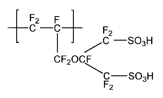
スルホン酸型官能基およびフッ素原子を有する単位は、1種を単独で用いてもよく、2種以上を組み合わせて用いてもよい。
含フッ素ポリマー(I)は、含フッ素オレフィンに基づく単位、並びに、スルホン酸型官能基およびフッ素原子を有する単位以外の、他のモノマーに基づく単位を含んでいてもよい。
他のモノマーの具体例としては、CF2=CFRf6(ただし、Rf6は炭素数2~10のペルフルオロアルキル基である。)、CF2=CF-ORf7(ただし、Rf7は炭素数1~10のペルフルオロアルキル基である。)、CF2=CFO(CF2)vCF=CF2(ただし、vは1~3の整数である。)が挙げられる。
他のモノマーに基づく単位の含有量は、イオン交換性能の維持の点から、含フッ素ポリマー(I)中の全単位に対して、30質量%以下が好ましい。
他のモノマーの具体例としては、CF2=CFRf6(ただし、Rf6は炭素数2~10のペルフルオロアルキル基である。)、CF2=CF-ORf7(ただし、Rf7は炭素数1~10のペルフルオロアルキル基である。)、CF2=CFO(CF2)vCF=CF2(ただし、vは1~3の整数である。)が挙げられる。
他のモノマーに基づく単位の含有量は、イオン交換性能の維持の点から、含フッ素ポリマー(I)中の全単位に対して、30質量%以下が好ましい。
固体高分子電解質膜は、単層構造であっても、多層構造であってもよい。多層構造である場合、例えば、含フッ素ポリマー(I)を含み、イオン交換容量が互いに異なる層を複数積層させる態様が挙げられる。
(固体高分子電解質膜の製造方法)
固体高分子電解質膜は、イオン交換基に変換できる基を有する含フッ素モノマー(以下、含フッ素モノマー(I’)ともいう。)のポリマー(以下、「含フッ素ポリマー(I’)」ともいう。)および織布を含む膜(以下「前駆体膜」ともいう。)を製造し、次に、前駆体膜中のイオン交換基に変換できる基をイオン交換基に変換して製造するのが好ましい。
固体高分子電解質膜は、イオン交換基に変換できる基を有する含フッ素モノマー(以下、含フッ素モノマー(I’)ともいう。)のポリマー(以下、「含フッ素ポリマー(I’)」ともいう。)および織布を含む膜(以下「前駆体膜」ともいう。)を製造し、次に、前駆体膜中のイオン交換基に変換できる基をイオン交換基に変換して製造するのが好ましい。
織布の形態は、上述した通りである。
含フッ素ポリマー(I’)としては、スルホン酸型官能基に変換できる基を有する含フッ素モノマー(以下、「含フッ素モノマー(S’)」ともいう。)のポリマー(以下、「含フッ素ポリマー(S’)」ともいう。)が好ましく、含フッ素オレフィンと、スルホン酸型官能基に変換できる基およびフッ素原子を有するモノマーとの共重合ポリマーが特に好ましい。
以下、含フッ素ポリマー(S’)について詳述する。
含フッ素ポリマー(I’)としては、スルホン酸型官能基に変換できる基を有する含フッ素モノマー(以下、「含フッ素モノマー(S’)」ともいう。)のポリマー(以下、「含フッ素ポリマー(S’)」ともいう。)が好ましく、含フッ素オレフィンと、スルホン酸型官能基に変換できる基およびフッ素原子を有するモノマーとの共重合ポリマーが特に好ましい。
以下、含フッ素ポリマー(S’)について詳述する。
含フッ素ポリマー(S’)の共重合の方法は、溶液重合、懸濁重合、乳化重合等の公知の方法を採用できる。
含フッ素オレフィンとしては、先に例示したものが挙げられ、モノマーの製造コスト、他のモノマーとの反応性、得られる含フッ素ポリマー(S)の特性に優れる点から、TFEが好ましい。
含フッ素オレフィンは、1種を単独で用いてもよく、2種以上を組み合わせて用いてもよい。
含フッ素オレフィンは、1種を単独で用いてもよく、2種以上を組み合わせて用いてもよい。
含フッ素モノマー(S’)としては、分子中に1個以上のフッ素原子を有し、エチレン性の二重結合を有し、かつ、スルホン酸型官能基に変換できる基を有する化合物が挙げられる。
含フッ素モノマー(S’)としては、モノマーの製造コスト、他のモノマーとの反応性、得られる含フッ素ポリマー(S)の特性に優れる点から、式(2)で表される化合物が好ましい。
式(2) CF2=CF-L-(A)n
式(2)中のLおよびnの定義は、上述した通りである。
Aは、スルホン酸型官能基に変換できる基である。スルホン酸型官能基に変換できる基は、加水分解によってスルホン酸型官能基に変換し得る官能基が好ましい。スルホン酸型官能基に変換できる基の具体例としては、-SO2F、-SO2Cl、-SO2Brが挙げられる。
含フッ素モノマー(S’)としては、モノマーの製造コスト、他のモノマーとの反応性、得られる含フッ素ポリマー(S)の特性に優れる点から、式(2)で表される化合物が好ましい。
式(2) CF2=CF-L-(A)n
式(2)中のLおよびnの定義は、上述した通りである。
Aは、スルホン酸型官能基に変換できる基である。スルホン酸型官能基に変換できる基は、加水分解によってスルホン酸型官能基に変換し得る官能基が好ましい。スルホン酸型官能基に変換できる基の具体例としては、-SO2F、-SO2Cl、-SO2Brが挙げられる。
式(2)で表される化合物としては、式(2-1)で表される化合物、式(2-2)で表される化合物、式(2-3)で表される化合物および式(2-4)で表される化合物が好ましい。
式(2-1) CF2=CF-O-Rf1-A
式(2-2) CF2=CF-Rf1-A
式(2-1) CF2=CF-O-Rf1-A
式(2-2) CF2=CF-Rf1-A

式中のRf1、Rf2、rおよびAの定義は、上述した通りである。

式中のRf1、Rf2、Rf3、r、mおよびAの定義は、上述した通りである。
式(2-1)で表される化合物および式(2-1)で表される化合物としては、式(2-5)で表される化合物が好ましい。
式(2-5) CF2=CF-(CF2)x-(OCF2CFY)y-O-(CF2)z-SO3M
式中のM、x、y、zおよびYの定義は、上述した通りである。
式(2-5) CF2=CF-(CF2)x-(OCF2CFY)y-O-(CF2)z-SO3M
式中のM、x、y、zおよびYの定義は、上述した通りである。
式(2-1)で表される化合物の具体例としては、以下の化合物が挙げられる。式中のwは1~8の整数であり、xは1~5の整数である。
CF2=CF-O-(CF2)w-SO2F
CF2=CF-O-CF2CF(CF3)-O-(CF2)w-SO2F
CF2=CF-[O-CF2CF(CF3)]x-SO2F
CF2=CF-O-(CF2)w-SO2F
CF2=CF-O-CF2CF(CF3)-O-(CF2)w-SO2F
CF2=CF-[O-CF2CF(CF3)]x-SO2F
式(2-2)で表される化合物の具体例としては、以下の化合物が挙げられる。式中のwは、1~8の整数である。
CF2=CF-(CF2)w-SO2F
CF2=CF-CF2-O-(CF2)w-SO2F
CF2=CF-(CF2)w-SO2F
CF2=CF-CF2-O-(CF2)w-SO2F
式(2-3)で表される化合物としては、式(2-3-1)で表される化合物が好ましい。

式中のRf4、Rf5、rおよびAの定義は、上述した通りである。
式(2-3-1)で表される化合物の具体例としては、以下が挙げられる。

式(2-4)で表される化合物としては、式(2-4-1)で表される化合物が好ましい。

式中のRf1、Rf2およびAの定義は、上述した通りである。
式(2-4-1)で表される化合物の具体例としては、以下が挙げられる。

含フッ素モノマー(S’)は、1種を単独で用いてもよく、2種以上を組み合わせて用いてもよい。
含フッ素ポリマー(S’)の製造には、含フッ素オレフィンおよび含フッ素モノマー(S’)に加えて、さらに他のモノマーを用いてもよい。他のモノマーとしては、先に例示したものが挙げられる。
含フッ素ポリマー(S’)の製造には、含フッ素オレフィンおよび含フッ素モノマー(S’)に加えて、さらに他のモノマーを用いてもよい。他のモノマーとしては、先に例示したものが挙げられる。
含フッ素ポリマー(I’)のイオン交換容量は、含フッ素ポリマー(I’)中のイオン交換基に変換できる基の含有量を変化させて、調整できる。
前駆体膜の製造方法の具体例としては、押し出し法が挙げられる。より具体的には、含フッ素ポリマー(I’)からなる膜(I’)を形成し、その後、膜(I’)、織布、膜(I’)の順に配置して、積層ロールまたは真空積層装置を用いてこれらを積層する方法が挙げられる。
前駆体膜中のイオン交換基に変換できる基をイオン交換基に変換する方法の具体例としては、前駆体膜に加水分解処理または酸型化処理等の処理を施す方法が挙げられる。
なかでも、前駆体膜とアルカリ性水溶液とを接触させる方法が好ましい。
なかでも、前駆体膜とアルカリ性水溶液とを接触させる方法が好ましい。
前駆体膜とアルカリ性水溶液とを接触させる方法の具体例としては、前駆体膜をアルカリ性水溶液中に浸漬する方法、前駆体膜の表面にアルカリ性水溶液をスプレー塗布する方法が挙げられる。
アルカリ性水溶液の温度は、30~100℃が好ましく、40~100℃が特に好ましい。前駆体膜とアルカリ性水溶液との接触時間は、3~150分が好ましく、5~50分が特に好ましい。
アルカリ性水溶液の温度は、30~100℃が好ましく、40~100℃が特に好ましい。前駆体膜とアルカリ性水溶液との接触時間は、3~150分が好ましく、5~50分が特に好ましい。
アルカリ性水溶液は、アルカリ金属水酸化物、水溶性有機溶剤および水を含むのが好ましい。
アルカリ金属水酸化物としては、水酸化ナトリウムおよび水酸化カリウムが挙げられる。
本明細書において、水溶性有機溶剤とは、水に容易に溶解する有機溶剤であり、具体的には、水1000ml(20℃)に対する溶解性が、0.1g以上の有機溶剤が好ましく、0.5g以上の有機溶剤が特に好ましい。水溶性有機溶剤は、非プロトン性有機溶剤、アルコール類およびアミノアルコール類からなる群より選ばれる少なくとも1種を含むのが好ましく、非プロトン性有機溶剤を含むのが特に好ましい。
水溶性有機溶剤は、1種を単独で用いてもよく、2種以上を組み合わせて用いてもよい。
アルカリ金属水酸化物としては、水酸化ナトリウムおよび水酸化カリウムが挙げられる。
本明細書において、水溶性有機溶剤とは、水に容易に溶解する有機溶剤であり、具体的には、水1000ml(20℃)に対する溶解性が、0.1g以上の有機溶剤が好ましく、0.5g以上の有機溶剤が特に好ましい。水溶性有機溶剤は、非プロトン性有機溶剤、アルコール類およびアミノアルコール類からなる群より選ばれる少なくとも1種を含むのが好ましく、非プロトン性有機溶剤を含むのが特に好ましい。
水溶性有機溶剤は、1種を単独で用いてもよく、2種以上を組み合わせて用いてもよい。
非プロトン性有機溶剤の具体例としては、ジメチルスルホキシド、N,N-ジメチルホルムアミド、N,N-ジメチルアセトアミド、N-メチル-2-ピロリドン、N-エチル-2-ピロリドンが挙げられ、ジメチルスルホキシドが好ましい。
アルコール類の具体例としては、メタノール、エタノール、イソプロパノール、ブタノール、メトキシエトキシエタノール、ブトキシエタノール、ブチルカルビトール、ヘキシルオキシエタノール、オクタノール、1-メトキシ-2-プロパノール、エチレングリコールが挙げられる。
アミノアルコール類の具体例としては、エタノールアミン、N-メチルエタノールアミン、N-エチルエタノールアミン、1-アミノ-2-プロパノール、1-アミノ-3-プロパノール、2-アミノエトキシエタノール、2-アミノチオエトキシエタノール、2-アミノ-2-メチル-1-プロパノールが挙げられる。
アルコール類の具体例としては、メタノール、エタノール、イソプロパノール、ブタノール、メトキシエトキシエタノール、ブトキシエタノール、ブチルカルビトール、ヘキシルオキシエタノール、オクタノール、1-メトキシ-2-プロパノール、エチレングリコールが挙げられる。
アミノアルコール類の具体例としては、エタノールアミン、N-メチルエタノールアミン、N-エチルエタノールアミン、1-アミノ-2-プロパノール、1-アミノ-3-プロパノール、2-アミノエトキシエタノール、2-アミノチオエトキシエタノール、2-アミノ-2-メチル-1-プロパノールが挙げられる。
アルカリ金属水酸化物の濃度は、アルカリ性水溶液中、1~60質量%が好ましく、3~55質量%が特に好ましい。
水溶性有機溶剤の含有量は、アルカリ性水溶液中、1~60質量%が好ましく、3~55質量%が特に好ましい。
水の濃度は、アルカリ性水溶液中、39~80質量%が好ましい。
水溶性有機溶剤の含有量は、アルカリ性水溶液中、1~60質量%が好ましく、3~55質量%が特に好ましい。
水の濃度は、アルカリ性水溶液中、39~80質量%が好ましい。
前駆体膜とアルカリ性水溶液との接触後に、アルカリ性水溶液を除去する処理を行ってもよい。アルカリ性水溶液を除去する方法としては、例えば、アルカリ性水溶液で接触させた前駆体膜を水洗する方法が挙げられる。
前駆体膜とアルカリ性水溶液との接触後に、得られた膜を酸性水溶液と接触させて、イオン交換基を酸型に変換してもよい。
前駆体膜と酸性水溶液とを接触させる方法の具体例としては、前駆体膜を酸性水溶液中に浸漬する方法、前駆体膜の表面に酸性水溶液をスプレー塗布する方法が挙げられる。
酸性水溶液は、酸成分および水を含むのが好ましい。
酸成分の具体例としては、塩酸、硫酸が挙げられる。
前駆体膜と酸性水溶液とを接触させる方法の具体例としては、前駆体膜を酸性水溶液中に浸漬する方法、前駆体膜の表面に酸性水溶液をスプレー塗布する方法が挙げられる。
酸性水溶液は、酸成分および水を含むのが好ましい。
酸成分の具体例としては、塩酸、硫酸が挙げられる。
<アノードおよびカソード>
アノードおよびカソードはそれぞれ、触媒層を有する。図2の例では、アノード22およびカソード24はそれぞれ、触媒層26およびガス拡散層28を有する。
アノードおよびカソードはそれぞれ、触媒層を有する。図2の例では、アノード22およびカソード24はそれぞれ、触媒層26およびガス拡散層28を有する。
触媒層の具体例としては、触媒と、イオン交換基を有するポリマーとを含む層が挙げられる。
触媒の具体例としては、カーボン担体に、白金、白金合金またはコアシェル構造を有する白金を含む触媒を担持した担持触媒、酸化イリジウム触媒、酸化イリジウムを含有する合金、コアシェル構造を有する酸化イリジウムを含有する触媒が挙げられる。カーボン担体としては、カーボンブラック粉末が挙げられる。
イオン交換基を有するポリマーとしては、イオン交換基を有する含フッ素ポリマーが挙げられる。
触媒の具体例としては、カーボン担体に、白金、白金合金またはコアシェル構造を有する白金を含む触媒を担持した担持触媒、酸化イリジウム触媒、酸化イリジウムを含有する合金、コアシェル構造を有する酸化イリジウムを含有する触媒が挙げられる。カーボン担体としては、カーボンブラック粉末が挙げられる。
イオン交換基を有するポリマーとしては、イオン交換基を有する含フッ素ポリマーが挙げられる。
ガス拡散層は、触媒層に均一にガスを拡散させる機能および集電体としての機能を有する。ガス拡散層の具体例としては、カーボンペーパー、カーボンクロス、カーボンフェルトが挙げられる。
ガス拡散層は、PTFE等によって撥水化処理されているのが好ましい。
図1の膜電極接合体においてはガス拡散層28が含まれるが、ガス拡散層は任意の部材であり、膜電極接合体に含まれていなくてもよい。
ガス拡散層は、PTFE等によって撥水化処理されているのが好ましい。
図1の膜電極接合体においてはガス拡散層28が含まれるが、ガス拡散層は任意の部材であり、膜電極接合体に含まれていなくてもよい。
<膜電極接合体の製造方法>
膜電極接合体の製造方法としては、例えば、固体高分子電解質膜上に触媒層を形成して、得られた接合体をさらにガス拡散層で挟み込む方法、および、ガス拡散層上に触媒層を形成して電極(アノード、カソード)とし、固体高分子電解質膜をこの電極で挟み込む方法が挙げられる。
なお、触媒層の製造方法は、触媒層形成用塗工液を所定の位置に塗布して、必要に応じて乾燥させる方法が挙げられる。触媒層形成用塗工液は、イオン交換基を有するポリマーおよび触媒を分散媒に分散させた液である。
膜電極接合体の製造方法としては、例えば、固体高分子電解質膜上に触媒層を形成して、得られた接合体をさらにガス拡散層で挟み込む方法、および、ガス拡散層上に触媒層を形成して電極(アノード、カソード)とし、固体高分子電解質膜をこの電極で挟み込む方法が挙げられる。
なお、触媒層の製造方法は、触媒層形成用塗工液を所定の位置に塗布して、必要に応じて乾燥させる方法が挙げられる。触媒層形成用塗工液は、イオン交換基を有するポリマーおよび触媒を分散媒に分散させた液である。
<用途>
本発明の膜電極接合体は、水電解装置(具体的には、固体高分子型水電解装置)に用いる。水電解装置における膜電極接合体は、陽極室と陰極室とに仕切る位置に配置されるため、水電解装置の運転時に膜電極接合体に大きな圧力がかかる場合がある。このような場合であっても、本発明の膜電極接合体は膜強度に優れるため、水電解装置に適用した際の膜電極接合体の破損を抑制できる。
本発明の膜電極接合体は、水電解装置(具体的には、固体高分子型水電解装置)に用いる。水電解装置における膜電極接合体は、陽極室と陰極室とに仕切る位置に配置されるため、水電解装置の運転時に膜電極接合体に大きな圧力がかかる場合がある。このような場合であっても、本発明の膜電極接合体は膜強度に優れるため、水電解装置に適用した際の膜電極接合体の破損を抑制できる。
[水電解装置]
本発明の水電解装置は、上記膜電極接合体を含む。本発明の膜電極接合体が強度に優れるため、本発明の水電解装置は耐久性に優れる。また、本発明の水電解装置においては、電解電圧を低くできる。
本発明の水電解装置は、上記膜電極接合体を含む。本発明の膜電極接合体が強度に優れるため、本発明の水電解装置は耐久性に優れる。また、本発明の水電解装置においては、電解電圧を低くできる。
以下、実施例を挙げて本発明を詳細に説明する。ただし本発明はこれらの実施例に限定されない。
[膜厚]
固体高分子電解質膜の膜厚Yは、上述の固体高分子電解質膜の説明の欄に記載された方法にしたがって算出した。
固体高分子電解質膜の膜厚Yは、上述の固体高分子電解質膜の説明の欄に記載された方法にしたがって算出した。
[含フッ素ポリマーのイオン交換容量]
乾燥窒素を流したグローブボックス中に含フッ素ポリマーを24時間おき、含フッ素ポリマーの乾燥質量を測定した。その後、含フッ素ポリマーを2モル/Lの塩化ナトリウム水溶液に60℃で1時間浸漬した。含フッ素ポリマーを超純水で洗浄した後、取り出し、含フッ素ポリマーを浸漬していた液を0.1モル/Lの水酸化ナトリウム水溶液で滴定することによって、含フッ素ポリマーのイオン交換容量X(ミリ当量/グラム乾燥樹脂)を求めた。
乾燥窒素を流したグローブボックス中に含フッ素ポリマーを24時間おき、含フッ素ポリマーの乾燥質量を測定した。その後、含フッ素ポリマーを2モル/Lの塩化ナトリウム水溶液に60℃で1時間浸漬した。含フッ素ポリマーを超純水で洗浄した後、取り出し、含フッ素ポリマーを浸漬していた液を0.1モル/Lの水酸化ナトリウム水溶液で滴定することによって、含フッ素ポリマーのイオン交換容量X(ミリ当量/グラム乾燥樹脂)を求めた。
[織布の目付量]
用いた織布原反を20×20cmサイズに裁断し、質量を測定した。上記測定を5回実施して、その平均値を基に、織布の目付量(g/m2)を求めた。
[織布を構成する経糸および緯糸の密度]
織布を構成する経糸および緯糸の密度は、以下の方法にしたがって算出した。経糸、緯糸それぞれについて、光学顕微鏡の観察像から、糸10本が構成される長さを5回測定した平均値を密度(本/インチ)に換算して算出した。
用いた織布原反を20×20cmサイズに裁断し、質量を測定した。上記測定を5回実施して、その平均値を基に、織布の目付量(g/m2)を求めた。
[織布を構成する経糸および緯糸の密度]
織布を構成する経糸および緯糸の密度は、以下の方法にしたがって算出した。経糸、緯糸それぞれについて、光学顕微鏡の観察像から、糸10本が構成される長さを5回測定した平均値を密度(本/インチ)に換算して算出した。
[織布の開口率]
用いた織布原反を20×20cmサイズに裁断したサンプルを用いて、上述の織布の説明の欄に記載された方法にしたがって算出した。
[織布を構成する経糸のデニール数および緯糸のデニール数]
織布を構成する経糸のデニール数および緯糸のデニール数は、以下の方法にしたがって算出した。ランダムに開口領域5か所を選択し、光学顕微鏡の観察像から開口割合を算出し、その平均値を開口率とした。
用いた織布原反を20×20cmサイズに裁断したサンプルを用いて、上述の織布の説明の欄に記載された方法にしたがって算出した。
[織布を構成する経糸のデニール数および緯糸のデニール数]
織布を構成する経糸のデニール数および緯糸のデニール数は、以下の方法にしたがって算出した。ランダムに開口領域5か所を選択し、光学顕微鏡の観察像から開口割合を算出し、その平均値を開口率とした。
[破裂試験]
後述する手順で得られた膜電極接合体を用いて、ミューレン破裂試験機M2-LD(東洋精機製作所製)で破裂試験を5回実施し、5回の測定値(破裂強度)の平均値に基づいて、以下の基準により評価した。
◎: 400kPa以上
〇: 210kPa超、400kPa未満
×: 210kPa以下
後述する手順で得られた膜電極接合体を用いて、ミューレン破裂試験機M2-LD(東洋精機製作所製)で破裂試験を5回実施し、5回の測定値(破裂強度)の平均値に基づいて、以下の基準により評価した。
◎: 400kPa以上
〇: 210kPa超、400kPa未満
×: 210kPa以下
[電解電圧評価試験]
TFEと後述するモノマー(X)とを共重合し、加水分解および酸処理を経て酸型としたポリマー(イオン交換容量:1.10ミリ当量/グラム乾燥樹脂)を水/エタノール=40/60(質量%)の溶媒に固形分濃度25.8%で分散させた分散液(以下、「分散液X」ともいう。)を得た。得られた分散液X(19.0g)に、エタノール(0.52g)、水(3.34g)を加え、さらに分散液中にイリジウムを76質量%含む酸化イリジウム触媒(田中貴金属社製 “ELC-1910”)(13.0g)を加えた。得られた混合物を遊星ビーズミル(回転数300rpm)で30分間処理した後、水(4.49g)、エタノール(4.53g)を加え、さらに遊星ビーズミル(回転数200rpm)で60分間処理して固形分濃度を40質量%としたアノード触媒インクを得た。
後述する手順で得られた固体高分子電解質膜の一方の表面上に、アノード触媒インクをイリジウムが2.0mg/cm2となるようバーコーターで塗工し、80℃で10分間乾燥させ、さらに150℃で15分間熱処理を施して、アノード触媒層付き電解質膜を得た。
カーボン粉末に白金を46質量%担持した担持触媒(田中貴金属工業社製 “TEC10E50E”)(11g)に水(59.4g)、エタノール(39.6g)を加え、超音波ホモジナイザーを用いて混合粉砕し、触媒の分散液を得た。
触媒の分散液に、分散液X(20.1g)とエタノール(11g)とゼオローラ-H(日本ゼオン製)(6.3g)とをあらかじめ混合・混練した混合液(29.2g)とを加えた。さらに、得られた分散液に、水(3.66g)、エタノール(7.63g)を加えてペイントコンディショナーを用いて60分間混合し、固形分濃度を10.0質量%とし、カソード触媒インクを得た。
ETFEシート上にカソード触媒インクをダイコーターで塗布し、80℃で乾燥させ、さらに150℃で15分間熱処理を施し、白金量が0.4mg/cm2のカソード触媒層デカールを得た。
触媒の分散液に、分散液X(20.1g)とエタノール(11g)とゼオローラ-H(日本ゼオン製)(6.3g)とをあらかじめ混合・混練した混合液(29.2g)とを加えた。さらに、得られた分散液に、水(3.66g)、エタノール(7.63g)を加えてペイントコンディショナーを用いて60分間混合し、固形分濃度を10.0質量%とし、カソード触媒インクを得た。
ETFEシート上にカソード触媒インクをダイコーターで塗布し、80℃で乾燥させ、さらに150℃で15分間熱処理を施し、白金量が0.4mg/cm2のカソード触媒層デカールを得た。
アノード触媒層付き電解質膜のアノード触媒層が形成されていない面とカソード触媒層デカールの触媒層が存在する面とを対向させ、プレス温度150℃でプレス時間2分間、圧力3MPaの条件で加熱プレスして、アノード触媒層付き電解質膜とカソード触媒層とを接合し、温度を70℃まで下げたのち圧力を解放して取り出し、カソード触媒層デカールのETFEシートを剥離して、電極面積25cm2の膜電極接合体を得た。
上記手順で得られた膜電極接合体を150℃で15分間熱処理した後、水電解評価治具EH50-25(Greenlight innovation社製)にセットした。
次に、まず、固体高分子電解質膜および両電極アイオノマーを十分含水させるため、アノード側とカソード側とに、伝導度1.0μS/cm以下、温度80℃、常圧の純水を50mL/minの流量で12時間供給した。その後、カソード側は窒素パージした。
窒素パージ後、アノード側には伝導度1.0μS/cm以下、温度80℃、常圧の純水を50mL/minの流量で供給し、カソード側での発生ガス圧は大気圧としながら、菊水電子工業製直流電源PWR1600Lにより0~50A(電流密度0~2A/cm2)の範囲で電流を2.5Aずつ段階的に上昇させた。各段階では10分間電流を保持し、電流50A(電流密度2A/cm2)のときの電解電圧を下記基準にて評価した。
◎: 1.85V以下
○: 1.85Vより大きく、1.95V以下
×: 1.95Vより大きい
[含フッ素ポリマー(S’-1)の製造]
CF2=CF2と下記式(X)で表されるモノマー(X)とを共重合して、含フッ素ポリマー(S’-1)(イオン交換容量:1.25ミリ当量/グラム乾燥樹脂)を得た。
CF2=CF-O-CF2CF(CF3)-O-CF2CF2-SO2F ・・・(X)
CF2=CF2と下記式(X)で表されるモノマー(X)とを共重合して、含フッ素ポリマー(S’-1)(イオン交換容量:1.25ミリ当量/グラム乾燥樹脂)を得た。
CF2=CF-O-CF2CF(CF3)-O-CF2CF2-SO2F ・・・(X)
[含フッ素ポリマー(S’-2)の製造]
CF2=CF2と下記式(Y)で表されるモノマー(Y)とを共重合して、含フッ素ポリマー(S’-2)(イオン交換容量:1.90ミリ当量/グラム乾燥樹脂)を得た。
CF2=CF2と下記式(Y)で表されるモノマー(Y)とを共重合して、含フッ素ポリマー(S’-2)(イオン交換容量:1.90ミリ当量/グラム乾燥樹脂)を得た。
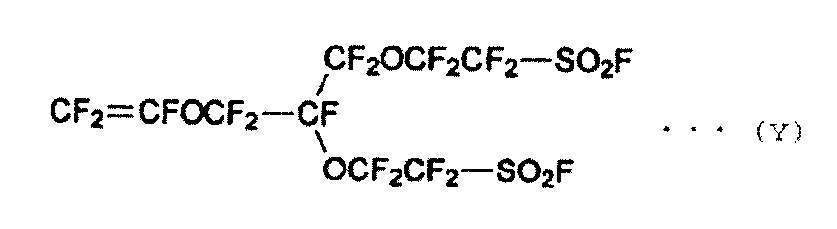
[含フッ素ポリマー(S’-3)の製造]
CF2=CF2とモノマー(X)とを共重合して、含フッ素ポリマー(S’-3)(イオン交換容量:1.00ミリ当量/グラム乾燥樹脂)を得た。
CF2=CF2とモノマー(X)とを共重合して、含フッ素ポリマー(S’-3)(イオン交換容量:1.00ミリ当量/グラム乾燥樹脂)を得た。
[含フッ素ポリマー(S’-4)の製造]
CF2=CF2と下記式(Z)で表されるモノマー(Z)とを共重合して、含フッ素ポリマー(S’-4)(イオン交換容量:1.78ミリ当量/グラム乾燥樹脂)を得た。
CF2=CF2と下記式(Z)で表されるモノマー(Z)とを共重合して、含フッ素ポリマー(S’-4)(イオン交換容量:1.78ミリ当量/グラム乾燥樹脂)を得た。

なお、上記[含フッ素ポリマー(S’-1)の製造]~[含フッ素ポリマー(S’-4)の製造]中に記載のイオン交換容量は、含フッ素ポリマー(S’-1)~(S’-4)を後述する手順で加水分解した際に得られる含フッ素ポリマーのイオン交換容量を表す。
[フィルムα1の製造]
含フッ素ポリマー(S’-1)を溶融押し出し法により成形し、含フッ素ポリマー(S’-1)からなるフィルムα1(膜厚:45μm)を得た。
含フッ素ポリマー(S’-1)を溶融押し出し法により成形し、含フッ素ポリマー(S’-1)からなるフィルムα1(膜厚:45μm)を得た。
[フィルムα2の製造]
含フッ素ポリマー(S’-1)を溶融押し出し法により成形し、含フッ素ポリマー(S’-1)からなるフィルムα2(膜厚:30μm)を得た。
含フッ素ポリマー(S’-1)を溶融押し出し法により成形し、含フッ素ポリマー(S’-1)からなるフィルムα2(膜厚:30μm)を得た。
[フィルムα3の製造]
含フッ素ポリマー(S’-1)を溶融押し出し法により成形し、含フッ素ポリマー(S’-1)からなるフィルムα3(膜厚:60μm)を得た。
含フッ素ポリマー(S’-1)を溶融押し出し法により成形し、含フッ素ポリマー(S’-1)からなるフィルムα3(膜厚:60μm)を得た。
[フィルムα4の製造]
含フッ素ポリマー(S’-1)を溶融押し出し法により成形し、含フッ素ポリマー(S’-1)からなるフィルムα4(膜厚:70μm)を得た。
含フッ素ポリマー(S’-1)を溶融押し出し法により成形し、含フッ素ポリマー(S’-1)からなるフィルムα4(膜厚:70μm)を得た。
[フィルムβ1の製造]
含フッ素ポリマー(S’-2)を溶融押し出し法により成形し、含フッ素ポリマー(S’-2)からなるフィルムβ1(膜厚:70μm)を得た。
含フッ素ポリマー(S’-2)を溶融押し出し法により成形し、含フッ素ポリマー(S’-2)からなるフィルムβ1(膜厚:70μm)を得た。
[フィルムγ1の製造]
含フッ素ポリマー(S’-3)を溶融押し出し法により成形し、含フッ素ポリマー(S’-3)からなるフィルムγ1(膜厚:30μm)を得た。
含フッ素ポリマー(S’-3)を溶融押し出し法により成形し、含フッ素ポリマー(S’-3)からなるフィルムγ1(膜厚:30μm)を得た。
[フィルムσ1の製造]
含フッ素ポリマー(S’-4)を溶融押し出し法により成形し、含フッ素ポリマー(S’-4)からなるフィルムσ1(膜厚:70μm)を得た。
含フッ素ポリマー(S’-4)を溶融押し出し法により成形し、含フッ素ポリマー(S’-4)からなるフィルムσ1(膜厚:70μm)を得た。
[織布の製造]
PPSからなる11.7デニールの糸を経糸および緯糸に用い、PPS糸の密度が100本/インチとなるように平織して織布A1を得た。織布A1の目付量は、10.2g/m2であった。なお、経糸および緯糸は、スリットヤーンで構成されていた。
また、経糸および緯糸を構成する材質の種類およびデニール、ならびに、織布の密度および目付量が表1の記載の値になるように変更した以外は、織布A1の製造と同様にして、織布A2~A4、B1~B2、C1~C2およびD1を製造した。
PPSからなる11.7デニールの糸を経糸および緯糸に用い、PPS糸の密度が100本/インチとなるように平織して織布A1を得た。織布A1の目付量は、10.2g/m2であった。なお、経糸および緯糸は、スリットヤーンで構成されていた。
また、経糸および緯糸を構成する材質の種類およびデニール、ならびに、織布の密度および目付量が表1の記載の値になるように変更した以外は、織布A1の製造と同様にして、織布A2~A4、B1~B2、C1~C2およびD1を製造した。
[実施例1]
PETフィルム/フィルムα1/織布A1/フィルムα1/PETフィルムをこの順で、重ね合わせた。重ね合わせた各部材を温度:200℃、面圧:30MPa/m2の平板プレス機にて10分間加熱圧着した後、両面の転写基材を温度50℃で剥離して、前駆体膜を得た。
PETフィルム/フィルムα1/織布A1/フィルムα1/PETフィルムをこの順で、重ね合わせた。重ね合わせた各部材を温度:200℃、面圧:30MPa/m2の平板プレス機にて10分間加熱圧着した後、両面の転写基材を温度50℃で剥離して、前駆体膜を得た。
ジメチルスルホキシド/水酸化カリウム/水=30/5.5/64.5(質量比)の溶液に、前駆体膜を95℃で30分間浸漬し、前駆体膜中のスルホン酸型官能基に変換できる基を加水分解して、K型のスルホン酸型官能基に変換した後、水洗した。その後、得られた膜を1M硫酸に浸漬し、末端基をK型からH型に変換した後、乾燥させ、固体高分子電解質膜を得た。
得られた固体高分子電解質膜を用いて、固体高分子電解質膜の膜厚Yの測定、破裂試験および水電解性能評価試験を実施した。結果を表1に示す。
得られた固体高分子電解質膜を用いて、固体高分子電解質膜の膜厚Yの測定、破裂試験および水電解性能評価試験を実施した。結果を表1に示す。
[実施例2~11、比較例1~8]
フィルムおよび織布の種類を表1に記載の通りに変更した以外は、実施例1と同じ方法で固体高分子電解質膜を作製し、固体高分子電解質膜の膜厚Yの測定、および、各種試験を実施した。ただし、比較例1および2では、織布を使用しなかった。結果を表1に示す。
フィルムおよび織布の種類を表1に記載の通りに変更した以外は、実施例1と同じ方法で固体高分子電解質膜を作製し、固体高分子電解質膜の膜厚Yの測定、および、各種試験を実施した。ただし、比較例1および2では、織布を使用しなかった。結果を表1に示す。
表1中の「デニール数(g/9000m)」は、織布を構成する経糸および緯糸のデニール数を表す。なお、実施例1~11および比較例1~8のいずれにおいても、織布を構成する経糸および緯糸のデニール数は同一であった。

図5は、固体高分子電解質膜に含まれる含フッ素ポリマーのイオン交換容量Xを横軸にとり、固体高分子電解質膜の膜厚Yを縦軸にとって、実施例および比較例の膜電極接合体毎にプロットしたグラフである。なお、グラフ中の点線は、式Y=240X-170で表される直線である。
図5に示すように、実施例1~11の膜電極接合体はいずれも、関係式Y1(すなわち、Y≦240X-170)を満たすことがわかる。
表1に示す通り、開口率が50%以上であり、経糸のデニール数および緯糸のデニール数がそれぞれ独立に2以上である織布を用い、関係式Y1を満たす固体高分子電解質膜を含む膜電極接合体を用いた場合、強度に優れ、かつ、水電解装置に適用した際に電解電圧を低減できることが確認できた(実施例1~11)。
図5に示すように、実施例1~11の膜電極接合体はいずれも、関係式Y1(すなわち、Y≦240X-170)を満たすことがわかる。
表1に示す通り、開口率が50%以上であり、経糸のデニール数および緯糸のデニール数がそれぞれ独立に2以上である織布を用い、関係式Y1を満たす固体高分子電解質膜を含む膜電極接合体を用いた場合、強度に優れ、かつ、水電解装置に適用した際に電解電圧を低減できることが確認できた(実施例1~11)。
これに対して、比較例1および2の膜電極接合体は、Y≦240X-170の式を満たすが、織布を含まない固体高分子電解質膜を用いたため、膜電極接合体の強度が劣っていた。
また、比較例3~5の膜電極接合体は、Y≦240X-170の式を満たすが、開口率が50%未満の織布を用いたため、水電解装置に適用した際に電解電圧が高くなった。
また、比較例6および7の膜電極接合体は、開口率が50%以上であり、経糸のデニール数および緯糸のデニール数がそれぞれ独立に2以上である織布を用いたが、Y≦240X-170の式を満たさないため、水電解装置に適用した際に電解電圧が高くなった。
また、比較例8の膜電極接合体は、Y≦240X-170の式を満たすが、経糸のデニール数および緯糸のデニール数がいずれも2未満の織布を用いたため、膜電極接合体の強度が劣っていた。
また、比較例3~5の膜電極接合体は、Y≦240X-170の式を満たすが、開口率が50%未満の織布を用いたため、水電解装置に適用した際に電解電圧が高くなった。
また、比較例6および7の膜電極接合体は、開口率が50%以上であり、経糸のデニール数および緯糸のデニール数がそれぞれ独立に2以上である織布を用いたが、Y≦240X-170の式を満たさないため、水電解装置に適用した際に電解電圧が高くなった。
また、比較例8の膜電極接合体は、Y≦240X-170の式を満たすが、経糸のデニール数および緯糸のデニール数がいずれも2未満の織布を用いたため、膜電極接合体の強度が劣っていた。
10 固体高分子電解質膜
12 電解質
14 織布
14a,14b,14c 糸
20 膜電極接合体
22 アノード
24 カソード
26 触媒層
28 ガス拡散層
t1,t2,t3,t4,t5,t6,t7,t8,t9 膜厚
12 電解質
14 織布
14a,14b,14c 糸
20 膜電極接合体
22 アノード
24 カソード
26 触媒層
28 ガス拡散層
t1,t2,t3,t4,t5,t6,t7,t8,t9 膜厚
なお、2019年2月8日に出願された日本特許出願2019-021696号の明細書、特許請求の範囲及び要約書の全内容をここに引用し、本発明の明細書の開示として、取り入れるものである。
Claims (13)
- 触媒層を有するアノードと、触媒層を有するカソードと、前記アノードと前記カソードとの間に配置された固体高分子電解質膜と、を含み、水電解装置に用いる膜電極接合体であって、
前記固体高分子電解質膜が、イオン交換基を有する含フッ素ポリマー、および、織布を含み、
前記織布の開口率が、50%以上であり、
前記織布を構成する経糸のデニール数および緯糸のデニール数がそれぞれ独立に、2以上であり、
前記固体高分子電解質膜の膜厚をYμm、前記含フッ素ポリマーのイオン交換容量をXミリ当量/グラム乾燥樹脂とした場合に、Y≦240X-170の関係を満たす、膜電極接合体。 - 前記織布の開口率が、60%以上であって、80%以下である、請求項1に記載の膜電極接合体。
- 前記織布を構成する経糸のデニール数および緯糸のデニール数がそれぞれ独立に、15以上であって、50以下である、請求項1または2に記載の膜電極接合体。
- 前記固体高分子電解質膜の膜厚Yが、20μm以上であって、150μm以下である、請求項1~3のいずれか1項に記載の膜電極接合体。
- 前記含フッ素ポリマーのイオン交換容量Xが、0.9~2.5ミリ当量/グラム乾燥樹脂である、請求項1~4のいずれか1項に記載の膜電極接合体。
- 前記織布を構成する経糸および緯糸が、ポリテトラフルオロエチレン、テトラフルオロエチレン-パーフルオロアルキルビニルエーテル共重合体、ポリエーテルエーテルケトン、および、ポリフェニレンサルファイドからなる群から選択される材料から構成される、請求項1~5のいずれか1項に記載の膜電極接合体。
- 前記織布を構成する経糸および緯糸の密度が、70本/インチ以上であって、150本/インチ以下である、請求項1~6のいずれか1項に記載の膜電極接合体。
- 前記イオン交換基が、スルホン酸型官能基である、請求項1~7のいずれか1項に記載の膜電極接合体
- 前記含フッ素ポリマーが、含フッ素オレフィンに基づく単位と、スルホン酸型官能基およびフッ素原子を有する単位とを含む、請求項1~8のいずれか1項に記載の膜電極接合体。
- 前記含フッ素オレフィンが、分子中に1個以上のフッ素原子を有する炭素数が2~3のフルオロオレフィンである、請求項9に記載の膜電極接合体。
- 前記スルホン酸型官能基およびフッ素原子を有する単位が、式(1)で表される単位である、請求項9に記載の膜電極接合体。
式(1) -[CF2-CF(-L-(SO3M)n)]-
Lはエーテル性酸素原子を含んでいてもよいn+1価のペルフルオロ炭化水素基であり、Mは水素原子、アルカリ金属または第4級アンモニウムカチオンであり、nは1または2である。 - 請求項1~11のいずれか1項に記載の膜電極接合体を含む、水電解装置。
- 固体高分子電解質膜であって、
前記固体高分子電解質膜が、イオン交換基を有する含フッ素ポリマー、および、織布を含み、
前記織布の開口率が、50%以上であり、
前記織布を構成する経糸のデニール数および緯糸のデニール数がそれぞれ独立に、2以上であり、
前記固体高分子電解質膜の膜厚をYμm、前記含フッ素ポリマーのイオン交換容量をXミリ当量/グラム乾燥樹脂とした場合に、Y≦240X-170の関係を満たす、固体高分子電解質膜。
Priority Applications (4)
| Application Number | Priority Date | Filing Date | Title |
|---|---|---|---|
| CN202080012825.9A CN113396245A (zh) | 2019-02-08 | 2020-02-05 | 膜电极接合体、水电解装置 |
| EP20752381.2A EP3922761A4 (en) | 2019-02-08 | 2020-02-05 | MEMBRANE ELECTRODE UNIT AND WATER ELECTROLYSIS DEVICE |
| JP2020571243A JP7414018B2 (ja) | 2019-02-08 | 2020-02-05 | 膜電極接合体、水電解装置 |
| US17/304,971 US20210324528A1 (en) | 2019-02-08 | 2021-06-29 | Membrane electrode assembly and water electrolysis apparatus |
Applications Claiming Priority (2)
| Application Number | Priority Date | Filing Date | Title |
|---|---|---|---|
| JP2019-021696 | 2019-02-08 | ||
| JP2019021696 | 2019-02-08 |
Related Child Applications (1)
| Application Number | Title | Priority Date | Filing Date |
|---|---|---|---|
| US17/304,971 Continuation US20210324528A1 (en) | 2019-02-08 | 2021-06-29 | Membrane electrode assembly and water electrolysis apparatus |
Publications (1)
| Publication Number | Publication Date |
|---|---|
| WO2020162511A1 true WO2020162511A1 (ja) | 2020-08-13 |
Family
ID=71947466
Family Applications (1)
| Application Number | Title | Priority Date | Filing Date |
|---|---|---|---|
| PCT/JP2020/004423 WO2020162511A1 (ja) | 2019-02-08 | 2020-02-05 | 膜電極接合体、水電解装置 |
Country Status (5)
| Country | Link |
|---|---|
| US (1) | US20210324528A1 (ja) |
| EP (1) | EP3922761A4 (ja) |
| JP (1) | JP7414018B2 (ja) |
| CN (1) | CN113396245A (ja) |
| WO (1) | WO2020162511A1 (ja) |
Cited By (7)
| Publication number | Priority date | Publication date | Assignee | Title |
|---|---|---|---|---|
| WO2022050363A1 (ja) * | 2020-09-04 | 2022-03-10 | Agc株式会社 | 膜電極接合体、固体高分子電解質膜、水電解装置および電解水素化装置 |
| WO2022085630A1 (ja) | 2020-10-22 | 2022-04-28 | Agc株式会社 | 電解質膜、電解装置およびレドックスフロー電池 |
| WO2023277068A1 (ja) | 2021-06-29 | 2023-01-05 | Agc株式会社 | 固体高分子型水電解用膜電極接合体および水電解装置 |
| WO2023085206A1 (ja) | 2021-11-09 | 2023-05-19 | Agc株式会社 | 固体高分子型水電解用膜電極接合体および水電解装置 |
| JP7392709B2 (ja) | 2019-02-28 | 2023-12-06 | Agc株式会社 | スルホン酸基含有ポリマー、フルオロスルホニル基含有ポリマーおよび液状組成物 |
| WO2024058177A1 (ja) * | 2022-09-13 | 2024-03-21 | Agc株式会社 | 固体高分子電解質膜、膜電極接合体、膜電極接合体の製造方法及び水電解装置 |
| WO2024058172A1 (ja) * | 2022-09-13 | 2024-03-21 | Agc株式会社 | 固体高分子電解質膜、膜電極接合体、膜電極接合体の製造方法及び水電解装置 |
Citations (7)
| Publication number | Priority date | Publication date | Assignee | Title |
|---|---|---|---|---|
| JPS59172524A (ja) * | 1983-03-23 | 1984-09-29 | Asahi Glass Co Ltd | イオン交換樹脂膜補強用布 |
| JPH0598486A (ja) * | 1991-10-02 | 1993-04-20 | Asahi Chem Ind Co Ltd | フツ素系イオン交換膜 |
| JPH1121687A (ja) | 1997-07-07 | 1999-01-26 | Japan Storage Battery Co Ltd | 固体高分子型水電解セル |
| WO2001006586A1 (fr) * | 1999-07-21 | 2001-01-25 | Asahi Glass Company, Limited | Pile a combustible du type a polyelectrolyte solide et procede de fabrication y relatif |
| JP2005078895A (ja) | 2003-08-29 | 2005-03-24 | Asahi Glass Co Ltd | 陽イオン交換膜、その製造方法及び固体高分子型燃料電池用膜電極接合体 |
| WO2018070444A1 (ja) * | 2016-10-13 | 2018-04-19 | 旭硝子株式会社 | アルカリ水電解用隔膜およびアルカリ水電解装置 |
| JP2019021696A (ja) | 2017-07-13 | 2019-02-07 | 三菱電機株式会社 | パネル角度切り替え構造、およびパネル角度切り替え構造を備えた電子機器 |
Family Cites Families (5)
| Publication number | Priority date | Publication date | Assignee | Title |
|---|---|---|---|---|
| AU535261B2 (en) * | 1979-11-27 | 1984-03-08 | Asahi Glass Company Limited | Ion exchange membrane cell |
| JPS617338A (ja) * | 1984-06-19 | 1986-01-14 | Asahi Glass Co Ltd | イオン交換樹脂膜 |
| JPH06231780A (ja) * | 1993-02-03 | 1994-08-19 | Asahi Glass Co Ltd | 改良した固体高分子電解質型燃料電池 |
| TWI694174B (zh) * | 2017-03-22 | 2020-05-21 | 日商旭化成股份有限公司 | 電解用電極、積層體、捲繞體、電解槽之製造方法、電極之更新方法、及捲繞體之製造方法 |
| JP7075792B2 (ja) * | 2017-03-22 | 2022-05-26 | 旭化成株式会社 | 積層体 |
-
2020
- 2020-02-05 CN CN202080012825.9A patent/CN113396245A/zh active Pending
- 2020-02-05 JP JP2020571243A patent/JP7414018B2/ja active Active
- 2020-02-05 WO PCT/JP2020/004423 patent/WO2020162511A1/ja unknown
- 2020-02-05 EP EP20752381.2A patent/EP3922761A4/en active Pending
-
2021
- 2021-06-29 US US17/304,971 patent/US20210324528A1/en active Pending
Patent Citations (7)
| Publication number | Priority date | Publication date | Assignee | Title |
|---|---|---|---|---|
| JPS59172524A (ja) * | 1983-03-23 | 1984-09-29 | Asahi Glass Co Ltd | イオン交換樹脂膜補強用布 |
| JPH0598486A (ja) * | 1991-10-02 | 1993-04-20 | Asahi Chem Ind Co Ltd | フツ素系イオン交換膜 |
| JPH1121687A (ja) | 1997-07-07 | 1999-01-26 | Japan Storage Battery Co Ltd | 固体高分子型水電解セル |
| WO2001006586A1 (fr) * | 1999-07-21 | 2001-01-25 | Asahi Glass Company, Limited | Pile a combustible du type a polyelectrolyte solide et procede de fabrication y relatif |
| JP2005078895A (ja) | 2003-08-29 | 2005-03-24 | Asahi Glass Co Ltd | 陽イオン交換膜、その製造方法及び固体高分子型燃料電池用膜電極接合体 |
| WO2018070444A1 (ja) * | 2016-10-13 | 2018-04-19 | 旭硝子株式会社 | アルカリ水電解用隔膜およびアルカリ水電解装置 |
| JP2019021696A (ja) | 2017-07-13 | 2019-02-07 | 三菱電機株式会社 | パネル角度切り替え構造、およびパネル角度切り替え構造を備えた電子機器 |
Non-Patent Citations (1)
| Title |
|---|
| See also references of EP3922761A4 |
Cited By (7)
| Publication number | Priority date | Publication date | Assignee | Title |
|---|---|---|---|---|
| JP7392709B2 (ja) | 2019-02-28 | 2023-12-06 | Agc株式会社 | スルホン酸基含有ポリマー、フルオロスルホニル基含有ポリマーおよび液状組成物 |
| WO2022050363A1 (ja) * | 2020-09-04 | 2022-03-10 | Agc株式会社 | 膜電極接合体、固体高分子電解質膜、水電解装置および電解水素化装置 |
| WO2022085630A1 (ja) | 2020-10-22 | 2022-04-28 | Agc株式会社 | 電解質膜、電解装置およびレドックスフロー電池 |
| WO2023277068A1 (ja) | 2021-06-29 | 2023-01-05 | Agc株式会社 | 固体高分子型水電解用膜電極接合体および水電解装置 |
| WO2023085206A1 (ja) | 2021-11-09 | 2023-05-19 | Agc株式会社 | 固体高分子型水電解用膜電極接合体および水電解装置 |
| WO2024058177A1 (ja) * | 2022-09-13 | 2024-03-21 | Agc株式会社 | 固体高分子電解質膜、膜電極接合体、膜電極接合体の製造方法及び水電解装置 |
| WO2024058172A1 (ja) * | 2022-09-13 | 2024-03-21 | Agc株式会社 | 固体高分子電解質膜、膜電極接合体、膜電極接合体の製造方法及び水電解装置 |
Also Published As
| Publication number | Publication date |
|---|---|
| JP7414018B2 (ja) | 2024-01-16 |
| JPWO2020162511A1 (ja) | 2021-12-23 |
| EP3922761A4 (en) | 2022-12-14 |
| EP3922761A1 (en) | 2021-12-15 |
| US20210324528A1 (en) | 2021-10-21 |
| CN113396245A (zh) | 2021-09-14 |
Similar Documents
| Publication | Publication Date | Title |
|---|---|---|
| WO2020162511A1 (ja) | 膜電極接合体、水電解装置 | |
| JP7384036B2 (ja) | 固体高分子電解質膜、膜電極接合体および水電解装置 | |
| US10944121B2 (en) | Polymer electrolyte film | |
| US20170012313A1 (en) | Polymer electrolyte membrane | |
| US20220396890A1 (en) | Ion exchange membrane with catalyst layer, ion exchange membrane and electrolytic hydrogenation apparatus | |
| JPWO2016186085A1 (ja) | イオン交換膜 | |
| JP7393601B2 (ja) | イオン交換膜、レドックスフロー電池 | |
| JP7188395B2 (ja) | レドックスフロー電池に好適なイオン交換膜 | |
| WO2022050363A1 (ja) | 膜電極接合体、固体高分子電解質膜、水電解装置および電解水素化装置 | |
| WO2022085630A1 (ja) | 電解質膜、電解装置およびレドックスフロー電池 | |
| JP4234573B2 (ja) | 固体高分子型燃料電池用電解質膜の製造方法 | |
| WO2024058177A1 (ja) | 固体高分子電解質膜、膜電極接合体、膜電極接合体の製造方法及び水電解装置 | |
| WO2023085206A1 (ja) | 固体高分子型水電解用膜電極接合体および水電解装置 | |
| WO2024058172A1 (ja) | 固体高分子電解質膜、膜電極接合体、膜電極接合体の製造方法及び水電解装置 | |
| WO2020054777A1 (ja) | ペレットの製造方法、ペレット及びイオン交換膜 | |
| JP4188789B2 (ja) | 固体高分子型燃料電池用電解質膜の製造方法 | |
| WO2020105600A1 (ja) | 複合粒子およびイオン交換膜 | |
| JP2019085548A (ja) | 隔膜 |
Legal Events
| Date | Code | Title | Description |
|---|---|---|---|
| 121 | Ep: the epo has been informed by wipo that ep was designated in this application |
Ref document number: 20752381 Country of ref document: EP Kind code of ref document: A1 |
|
| ENP | Entry into the national phase |
Ref document number: 2020571243 Country of ref document: JP Kind code of ref document: A |
|
| NENP | Non-entry into the national phase |
Ref country code: DE |
|
| ENP | Entry into the national phase |
Ref document number: 2020752381 Country of ref document: EP Effective date: 20210908 |