WO2020153007A1 - 分離膜モジュール及びそれを用いた液体処理システム - Google Patents
分離膜モジュール及びそれを用いた液体処理システム Download PDFInfo
- Publication number
- WO2020153007A1 WO2020153007A1 PCT/JP2019/047508 JP2019047508W WO2020153007A1 WO 2020153007 A1 WO2020153007 A1 WO 2020153007A1 JP 2019047508 W JP2019047508 W JP 2019047508W WO 2020153007 A1 WO2020153007 A1 WO 2020153007A1
- Authority
- WO
- WIPO (PCT)
- Prior art keywords
- separation membrane
- membrane element
- water
- membrane module
- degassing
- Prior art date
- Legal status (The legal status is an assumption and is not a legal conclusion. Google has not performed a legal analysis and makes no representation as to the accuracy of the status listed.)
- Ceased
Links
Images





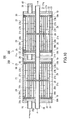


Classifications
-
- B—PERFORMING OPERATIONS; TRANSPORTING
- B01—PHYSICAL OR CHEMICAL PROCESSES OR APPARATUS IN GENERAL
- B01D—SEPARATION
- B01D19/00—Degasification of liquids
- B01D19/0031—Degasification of liquids by filtration
-
- B—PERFORMING OPERATIONS; TRANSPORTING
- B01—PHYSICAL OR CHEMICAL PROCESSES OR APPARATUS IN GENERAL
- B01D—SEPARATION
- B01D61/00—Processes of separation using semi-permeable membranes, e.g. dialysis, osmosis or ultrafiltration; Apparatus, accessories or auxiliary operations specially adapted therefor
- B01D61/02—Reverse osmosis; Hyperfiltration ; Nanofiltration
- B01D61/08—Apparatus therefor
-
- B—PERFORMING OPERATIONS; TRANSPORTING
- B01—PHYSICAL OR CHEMICAL PROCESSES OR APPARATUS IN GENERAL
- B01D—SEPARATION
- B01D61/00—Processes of separation using semi-permeable membranes, e.g. dialysis, osmosis or ultrafiltration; Apparatus, accessories or auxiliary operations specially adapted therefor
- B01D61/14—Ultrafiltration; Microfiltration
- B01D61/18—Apparatus therefor
-
- B—PERFORMING OPERATIONS; TRANSPORTING
- B01—PHYSICAL OR CHEMICAL PROCESSES OR APPARATUS IN GENERAL
- B01D—SEPARATION
- B01D61/00—Processes of separation using semi-permeable membranes, e.g. dialysis, osmosis or ultrafiltration; Apparatus, accessories or auxiliary operations specially adapted therefor
- B01D61/58—Multistep processes
-
- B—PERFORMING OPERATIONS; TRANSPORTING
- B01—PHYSICAL OR CHEMICAL PROCESSES OR APPARATUS IN GENERAL
- B01D—SEPARATION
- B01D63/00—Apparatus in general for separation processes using semi-permeable membranes
- B01D63/02—Hollow fibre modules
- B01D63/04—Hollow fibre modules comprising multiple hollow fibre assemblies
-
- B—PERFORMING OPERATIONS; TRANSPORTING
- B01—PHYSICAL OR CHEMICAL PROCESSES OR APPARATUS IN GENERAL
- B01D—SEPARATION
- B01D63/00—Apparatus in general for separation processes using semi-permeable membranes
- B01D63/10—Spiral-wound membrane modules
- B01D63/101—Spiral winding
-
- C—CHEMISTRY; METALLURGY
- C02—TREATMENT OF WATER, WASTE WATER, SEWAGE, OR SLUDGE
- C02F—TREATMENT OF WATER, WASTE WATER, SEWAGE, OR SLUDGE
- C02F1/00—Treatment of water, waste water, or sewage
- C02F1/20—Treatment of water, waste water, or sewage by degassing, i.e. liberation of dissolved gases
-
- C—CHEMISTRY; METALLURGY
- C02—TREATMENT OF WATER, WASTE WATER, SEWAGE, OR SLUDGE
- C02F—TREATMENT OF WATER, WASTE WATER, SEWAGE, OR SLUDGE
- C02F1/00—Treatment of water, waste water, or sewage
- C02F1/44—Treatment of water, waste water, or sewage by dialysis, osmosis or reverse osmosis
-
- B—PERFORMING OPERATIONS; TRANSPORTING
- B01—PHYSICAL OR CHEMICAL PROCESSES OR APPARATUS IN GENERAL
- B01D—SEPARATION
- B01D2311/00—Details relating to membrane separation process operations and control
- B01D2311/04—Specific process operations in the feed stream; Feed pretreatment
-
- B—PERFORMING OPERATIONS; TRANSPORTING
- B01—PHYSICAL OR CHEMICAL PROCESSES OR APPARATUS IN GENERAL
- B01D—SEPARATION
- B01D2311/00—Details relating to membrane separation process operations and control
- B01D2311/06—Specific process operations in the permeate stream
-
- B—PERFORMING OPERATIONS; TRANSPORTING
- B01—PHYSICAL OR CHEMICAL PROCESSES OR APPARATUS IN GENERAL
- B01D—SEPARATION
- B01D2311/00—Details relating to membrane separation process operations and control
- B01D2311/26—Further operations combined with membrane separation processes
- B01D2311/2653—Degassing
-
- B—PERFORMING OPERATIONS; TRANSPORTING
- B01—PHYSICAL OR CHEMICAL PROCESSES OR APPARATUS IN GENERAL
- B01D—SEPARATION
- B01D2313/00—Details relating to membrane modules or apparatus
- B01D2313/16—Specific vents
-
- B—PERFORMING OPERATIONS; TRANSPORTING
- B01—PHYSICAL OR CHEMICAL PROCESSES OR APPARATUS IN GENERAL
- B01D—SEPARATION
- B01D2317/00—Membrane module arrangements within a plant or an apparatus
- B01D2317/02—Elements in series
- B01D2317/025—Permeate series
-
- B—PERFORMING OPERATIONS; TRANSPORTING
- B01—PHYSICAL OR CHEMICAL PROCESSES OR APPARATUS IN GENERAL
- B01D—SEPARATION
- B01D2317/00—Membrane module arrangements within a plant or an apparatus
- B01D2317/06—Use of membrane modules of the same kind
-
- B—PERFORMING OPERATIONS; TRANSPORTING
- B01—PHYSICAL OR CHEMICAL PROCESSES OR APPARATUS IN GENERAL
- B01D—SEPARATION
- B01D2317/00—Membrane module arrangements within a plant or an apparatus
- B01D2317/08—Use of membrane modules of different kinds
-
- B—PERFORMING OPERATIONS; TRANSPORTING
- B01—PHYSICAL OR CHEMICAL PROCESSES OR APPARATUS IN GENERAL
- B01D—SEPARATION
- B01D2319/00—Membrane assemblies within one housing
- B01D2319/06—Use of membranes of different materials or properties within one module
-
- B—PERFORMING OPERATIONS; TRANSPORTING
- B01—PHYSICAL OR CHEMICAL PROCESSES OR APPARATUS IN GENERAL
- B01D—SEPARATION
- B01D61/00—Processes of separation using semi-permeable membranes, e.g. dialysis, osmosis or ultrafiltration; Apparatus, accessories or auxiliary operations specially adapted therefor
- B01D61/02—Reverse osmosis; Hyperfiltration ; Nanofiltration
- B01D61/025—Reverse osmosis; Hyperfiltration
-
- B—PERFORMING OPERATIONS; TRANSPORTING
- B01—PHYSICAL OR CHEMICAL PROCESSES OR APPARATUS IN GENERAL
- B01D—SEPARATION
- B01D61/00—Processes of separation using semi-permeable membranes, e.g. dialysis, osmosis or ultrafiltration; Apparatus, accessories or auxiliary operations specially adapted therefor
- B01D61/02—Reverse osmosis; Hyperfiltration ; Nanofiltration
- B01D61/027—Nanofiltration
-
- B—PERFORMING OPERATIONS; TRANSPORTING
- B01—PHYSICAL OR CHEMICAL PROCESSES OR APPARATUS IN GENERAL
- B01D—SEPARATION
- B01D61/00—Processes of separation using semi-permeable membranes, e.g. dialysis, osmosis or ultrafiltration; Apparatus, accessories or auxiliary operations specially adapted therefor
- B01D61/14—Ultrafiltration; Microfiltration
- B01D61/145—Ultrafiltration
-
- B—PERFORMING OPERATIONS; TRANSPORTING
- B01—PHYSICAL OR CHEMICAL PROCESSES OR APPARATUS IN GENERAL
- B01D—SEPARATION
- B01D61/00—Processes of separation using semi-permeable membranes, e.g. dialysis, osmosis or ultrafiltration; Apparatus, accessories or auxiliary operations specially adapted therefor
- B01D61/14—Ultrafiltration; Microfiltration
- B01D61/147—Microfiltration
-
- C—CHEMISTRY; METALLURGY
- C02—TREATMENT OF WATER, WASTE WATER, SEWAGE, OR SLUDGE
- C02F—TREATMENT OF WATER, WASTE WATER, SEWAGE, OR SLUDGE
- C02F1/00—Treatment of water, waste water, or sewage
- C02F1/44—Treatment of water, waste water, or sewage by dialysis, osmosis or reverse osmosis
- C02F1/441—Treatment of water, waste water, or sewage by dialysis, osmosis or reverse osmosis by reverse osmosis
-
- C—CHEMISTRY; METALLURGY
- C02—TREATMENT OF WATER, WASTE WATER, SEWAGE, OR SLUDGE
- C02F—TREATMENT OF WATER, WASTE WATER, SEWAGE, OR SLUDGE
- C02F1/00—Treatment of water, waste water, or sewage
- C02F1/44—Treatment of water, waste water, or sewage by dialysis, osmosis or reverse osmosis
- C02F1/442—Treatment of water, waste water, or sewage by dialysis, osmosis or reverse osmosis by nanofiltration
-
- C—CHEMISTRY; METALLURGY
- C02—TREATMENT OF WATER, WASTE WATER, SEWAGE, OR SLUDGE
- C02F—TREATMENT OF WATER, WASTE WATER, SEWAGE, OR SLUDGE
- C02F1/00—Treatment of water, waste water, or sewage
- C02F1/44—Treatment of water, waste water, or sewage by dialysis, osmosis or reverse osmosis
- C02F1/444—Treatment of water, waste water, or sewage by dialysis, osmosis or reverse osmosis by ultrafiltration or microfiltration
-
- C—CHEMISTRY; METALLURGY
- C02—TREATMENT OF WATER, WASTE WATER, SEWAGE, OR SLUDGE
- C02F—TREATMENT OF WATER, WASTE WATER, SEWAGE, OR SLUDGE
- C02F2103/00—Nature of the water, waste water, sewage or sludge to be treated
- C02F2103/02—Non-contaminated water, e.g. for industrial water supply
- C02F2103/04—Non-contaminated water, e.g. for industrial water supply for obtaining ultra-pure water
-
- C—CHEMISTRY; METALLURGY
- C02—TREATMENT OF WATER, WASTE WATER, SEWAGE, OR SLUDGE
- C02F—TREATMENT OF WATER, WASTE WATER, SEWAGE, OR SLUDGE
- C02F2103/00—Nature of the water, waste water, sewage or sludge to be treated
- C02F2103/08—Seawater, e.g. for desalination
-
- C—CHEMISTRY; METALLURGY
- C02—TREATMENT OF WATER, WASTE WATER, SEWAGE, OR SLUDGE
- C02F—TREATMENT OF WATER, WASTE WATER, SEWAGE, OR SLUDGE
- C02F2303/00—Specific treatment goals
- C02F2303/18—Removal of treatment agents after treatment
- C02F2303/185—The treatment agent being halogen or a halogenated compound
-
- Y—GENERAL TAGGING OF NEW TECHNOLOGICAL DEVELOPMENTS; GENERAL TAGGING OF CROSS-SECTIONAL TECHNOLOGIES SPANNING OVER SEVERAL SECTIONS OF THE IPC; TECHNICAL SUBJECTS COVERED BY FORMER USPC CROSS-REFERENCE ART COLLECTIONS [XRACs] AND DIGESTS
- Y02—TECHNOLOGIES OR APPLICATIONS FOR MITIGATION OR ADAPTATION AGAINST CLIMATE CHANGE
- Y02A—TECHNOLOGIES FOR ADAPTATION TO CLIMATE CHANGE
- Y02A20/00—Water conservation; Efficient water supply; Efficient water use
- Y02A20/124—Water desalination
- Y02A20/131—Reverse-osmosis
Definitions
- the present invention relates to a separation membrane module and a liquid treatment system using the same.
- the separation membrane module is used in a system for the purpose of desalination of seawater, production of pure water, wastewater treatment, production of oilfield injection water, etc. Depending on the intended use of the obtained water, dissolved substances such as oxygen and carbon dioxide need to be sufficiently removed from the water.
- Patent Document 1 describes that dissolved oxygen is removed from water by degassing under reduced pressure so as to have a predetermined dissolved oxygen concentration or less, and then the dissolved oxygen is further removed by an oxygen scavenger.
- Patent Document 2 describes a water treatment system in which a degassing membrane is provided between the first reverse osmosis membrane device of the first stage and the second reverse osmosis membrane device of the second stage.
- ⁇ Restrictions on the occupied area may be imposed on the system using the separation membrane module.
- the present invention aims to provide a separation membrane module that contributes to space saving of the system.
- the present invention is Container and A degassing membrane element disposed inside the container, A separation membrane element arranged inside the vessel, located upstream or downstream of the degassing membrane element in the flow direction of the liquid to be treated, for filtering the liquid;
- a separation membrane module comprising:
- the present invention provides A first separation membrane module having at least one selected from an MF membrane and a UF membrane, A second separation membrane module disposed downstream of the first separation membrane module in the flow direction of the liquid to be treated and treating the permeate of the first separation membrane module; Equipped with There is provided a liquid treatment system, wherein the second separation membrane module is the separation membrane module of the present invention.
- the degassing membrane element and the separation membrane element are arranged inside a common container, which contributes to space saving of the system.
- the area occupied by the system can be reduced by using the separation membrane module of the present invention.
- FIG. 1 is a configuration diagram of a separation membrane module according to the first embodiment of the present invention.
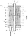
- FIG. 2 is a sectional view of a degassing membrane element used in the separation membrane module shown in FIG.
- FIG. 3 is a partially developed view of the separation membrane element used in the separation membrane module shown in FIG.
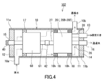
- FIG. 4 is a configuration diagram of a separation membrane module according to the second embodiment of the present invention.
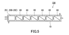
- FIG. 5 is a configuration diagram of a separation membrane module according to Modification 1.
- FIG. 6 is a configuration diagram of a separation membrane module according to Modification 2.
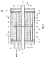
- FIG. 7 is a sectional view of a degassing membrane element according to Modification 3.
- FIG. 8 is a cross-sectional view of a degassing membrane element according to Modification 4.
- FIG. 1 is a configuration diagram of a separation membrane module according to the first embodiment of the present invention.
- FIG. 2 is a sectional view of a degassing membrane element used in the separation membrane module shown in
- FIG. 9 is a cross-sectional view of a degassing membrane element according to Modification 5.
- FIG. 10 is a cross-sectional view of a degassing membrane element according to Modification 6.
- FIG. 11 is a configuration diagram of a water treatment system using the separation membrane module shown in FIG.
- FIG. 12 is a configuration diagram of a water treatment system using the separation membrane module shown in FIG.
- FIG. 1 shows the configuration of a separation membrane module 100 according to the first embodiment.
- the separation membrane module 100 includes a container 10, a degassing membrane element 20, and a separation membrane element 60.
- the degassing membrane element 20 and the separation membrane element 60 are arranged inside the container 10.
- the degassing membrane element 20 is located upstream of the separation membrane element 60 in the direction of flow of the liquid to be treated.
- the degassing membrane element 20 removes dissolved gas from a liquid.
- the separation membrane element 60 is located downstream of the degassing membrane element 20 in the flow direction of the liquid to be treated.
- the liquid degassed by the degassing membrane element 20 flows into the separation membrane element 60.
- the separation membrane element 60 filters the liquid to generate a permeated liquid and a concentrated liquid.
- the separation membrane module 100 may be a hybrid module of the degassing membrane element 20 and the separation membrane element 60.
- the liquid to be treated (deaerated and filtered) by the separation membrane module 100 includes water.
- water is used herein as a representative of liquid.
- Water to be treated is sometimes referred to as "raw water”.
- the degassing membrane element 20 and the separation membrane element 60 are housed in one common container 10.
- the separation membrane module 100 is lightweight and compact compared with the case where these are housed in separate containers. Therefore, the separation membrane module 100 is suitable for a system that requires weight reduction and space saving. In addition, since each element can be replaced, the separation membrane module 100 has excellent maintainability.
- the separation membrane element 60 is located downstream of the degassing membrane element 20 in the water flow direction. According to such a positional relationship, the dissolved oxygen concentration of water in the degassing membrane element 20 is reduced, and thus there is an effect of suppressing biofouling in the separation membrane element 60. This is because the growth rate of microorganisms that cause biofouling depends on the dissolved oxygen concentration.
- the container 10 has a container body 11, a first end plate 12, and a second end plate 14.
- the container body 11 has a cylindrical shape and is made of a material having sufficient pressure resistance.
- the first end plate 12 is attached to the first end 11 a of the container body 11.
- the first end plate 12 closes the first end 11 a of the container body 11.
- the second end plate 14 is attached to the second end 11b of the container body 11.
- the second end plate 14 closes the second end 11 b of the container body 11.
- the container body 11 has a port 10a and a port 10b.
- Each of the port 10a and the port 10b is a port for communicating the inside and the outside of the container 10.
- the port 10a is provided at the first end 11a of the container body 11.
- the port 10b is provided at the second end 11b of the container body 11.
- the container body 11 is bilaterally symmetrical.
- the longitudinal direction of the container body 11 corresponds to the flow direction of water.
- the plug 40 is attached to the port 10a, whereby the port 10a is closed.
- the port 10a is an unused port.
- the port 10a may be omitted.
- the container 10 has a bilaterally asymmetric structure with respect to the flow direction of water to be treated.
- the bilaterally asymmetric structure is suitable for the separation membrane module 100 of the present embodiment.
- five ports are present in the container 10, which realizes a bilaterally asymmetric structure.
- the first end plate 12 may be provided with at least one port
- the second end plate 14 may be provided with at least one port.
- At least one port provided in the first end plate 12 includes a port 13 for evacuating the inside of the degassing membrane element 20.
- the at least one port provided in the first end plate 12 further includes a port 15 for introducing water to be treated inside the degassing membrane element 20.
- At least one port provided in the second end plate 14 includes a port 16 for guiding the permeated water generated by the separation membrane element 60 to the outside of the container 10.
- the number of at least one port provided on the first end plate 12 may be different from the number of at least one port provided on the second end plate 14.
- the first end plate 12 is provided with two ports 13 and 15, and the second end plate 14 is provided with only one port 16.
- the port 15 is used as the raw water inlet.
- Port 10b is used as the concentrated water outlet.
- Port 13 is used as a vacuum port.
- Port 16 is used as the permeate outlet.
- Each of the ports 10a, 10b, 13, 15 and 16 may be a simple opening or a nozzle-shaped opening as shown in FIG.
- the separation membrane module 100 further includes a support 18 arranged in the gap between the degassing membrane element 20 and the container 10.
- the support 18 has, for example, a ring shape, and surrounds the degassing membrane element 20 in the circumferential direction.
- the degassing membrane element 20 is fixed to the inner surface of the container 10 by the support 18.
- the degassing membrane element 20 is positioned inside the container 10 by the two supports 18.
- the support 18 has a through hole 18h that allows passage of water.
- the through hole 18h prevents a closed space from being formed inside the container 10. When water is introduced into the container 10, air escapes through the through holes 18h, so that a closed space is not formed inside the container 10. As a result, it is possible to prevent the degassing membrane element 20 from being damaged by the pressure difference.
- the support 18 may have only one through hole 18h or may have a plurality of through holes 18h.
- the separation membrane module 100 further includes a brine seal 17 arranged in the gap between the separation membrane element 60 and the container 10.
- the brine seal 17 has, for example, a ring shape and surrounds the separation membrane element 60 in the circumferential direction.
- the separation membrane element 60 is fixed to the inner surface of the container 10 by the brine seal 17.
- the inner space of the container 10 is partitioned by the brine seal 17 to prevent mixing of raw water and concentrated water.
- FIG. 2 shows a cross section of the degassing membrane element 20 used in the separation membrane module 100 shown in FIG.
- the degassing membrane element 20 has a shell 21, a plurality of hollow fiber membranes 24, an inlet 26p and an outlet 27q.
- the plurality of hollow fiber membranes 24 are arranged inside the shell 21.
- the water to be degassed is introduced into the shell 21 through the inlet 26p, contacts the plurality of hollow fiber membranes 24, and is then discharged from the shell 21 through the outlet 27q.
- dissolved gases such as oxygen and carbon dioxide are removed from water.
- the shell 21 has a cylindrical shape.
- the inlet 26p is located at one end of the shell 21, and the outlet 27q is located at the other end of the shell 21.
- the degassing membrane element 20 is, for example, an external pressure type hollow fiber membrane element.
- the water to be treated flows outside the hollow fiber membrane 24, and the inside of the hollow fiber membrane 24 is evacuated.
- an internal pressure type hollow fiber membrane element may be adopted.
- the water to be treated flows inside the hollow fiber membrane, and the outside of the hollow fiber membrane is evacuated.
- the degassing membrane element 20 further has a first tube 26 arranged inside the shell 21.
- the first pipe 26 extends from the inside of the shell 21 to the outside.
- the hollow fiber membrane 24 is arranged around the first tube 26.
- An inlet 26p of the degassing membrane element 20 is formed by one end of the first pipe 26.
- the first pipe 26 has a plurality of through holes 26h provided along the longitudinal direction. As indicated by the dashed arrow, the water introduced into the first pipe 26 diffuses into the shell 21 through these through holes 26h and contacts the hollow fiber membrane 24.
- the degassing membrane element 20 further has a second tube 27 arranged inside the shell 21.
- the second pipe 27 extends from the inside of the shell 21 to the outside.
- the hollow fiber membrane 24 is arranged around the second tube 27.
- An outlet 27q of the degassing membrane element 20 is formed by one end of the second pipe 27.
- the second pipe 27 has a plurality of through holes 27h provided along the longitudinal direction. As indicated by the dashed arrow, the water introduced into the shell 21 is collected in the second pipe 27 through these through holes 27h and discharged to the outside of the shell 21.
- the first pipe 26 serves as an inlet pipe and a distribution pipe.
- the second pipe 27 serves as an outlet pipe and a water collection pipe.
- the flow direction of water may be opposite to the direction shown in FIG.
- the first pipe 26 serves as an outlet pipe and a water collection pipe.
- the second pipe 27 serves as an inlet pipe and a distribution pipe.
- the central axis of the first pipe 26 may or may not coincide with the central axis of the second pipe 27.
- the degassing membrane element 20 further includes a baffle plate 29 arranged between the first pipe 26 and the second pipe 27 inside the shell 21.
- the baffle plate 29 has, for example, a disc shape in a plan view.
- the other end of the first pipe 26 and the other end of the second pipe 27 are abutted against the baffle plate 29 and closed.
- the plurality of hollow fiber membranes 24 penetrate the baffle plate 29.
- the baffle plate 29 partitions the internal space in which the hollow fiber membrane 24 is arranged into an upstream space 21a and a downstream space 21b.
- the first pipe 26 faces the upstream space 21a.
- the second pipe 27 faces the downstream space 21b.
- a gap 21t through which water can flow is secured between the shell 21 and the baffle plate 29. Water is supplied to the upstream space 21a through the first pipe 26 and flows into the downstream space 21b through the gap 21t.
- the degassing membrane element 20 further includes a lid 22, a first casting part 23 and a second casting part 25.
- the first casting part 23 is fitted to one end of the shell 21 and closes the shell 21.
- the lid 22 and the second casting part 25 are fitted to the other end of the shell 21 to close the shell 21.
- a vacuum drawing space 21s is secured between the lid 22 and the second casting part 25.
- the first casting part 23 bundles one end parts of the plurality of hollow fiber membranes 24.
- the second casting part 25 bundles the other ends of the plurality of hollow fiber membranes 24.
- One end of each of the hollow fiber membranes 24 is closed by the first casting part 23.
- the other ends of the plurality of hollow fiber membranes 24 extend to the end face of the second casting part 25, and open at the end face of the second casting part 25 toward the vacuum drawing space 21s.
- the first casting part 23 and the second casting part 25 are made of, for example, a resin filled between adjacent hollow fiber membranes 24.
- the lid 22 is provided with a port 28 for vacuuming so that the vacuuming space 21s can be vacuumed from the outside.
- the port 28 may be a simple opening or a nozzle-shaped opening.
- the degassing membrane element 20 described with reference to FIG. 2 enables efficient contact between the hollow fiber membrane 24 and water, and is suitable for the separation membrane module 100.
- the structure of the degassing membrane element that can be used in the separation membrane module 100 is not particularly limited.
- FIG. 3 shows the separation membrane element 60 shown in FIG. 1 in a partially expanded state.
- the separation membrane element 60 is a spiral wound type membrane element.
- the structure of the separation membrane element 60 is not limited to the spiral type.
- the separation membrane element 60 is composed of a separation membrane 62, a raw water spacer 63, and a permeated water spacer 64.
- the separation membrane element 60 is composed of a plurality of separation membranes 62, a plurality of raw water spacers 63 and a plurality of permeated water spacers 64.
- the plurality of separation membranes 62 are superposed on each other, sealed on three sides so as to have a bag-like structure, and wound around the water collection pipe 61.
- a raw water spacer 63 is arranged between the separation membranes 62 so as to be located outside the bag-shaped structure. The raw water spacer 63 secures a space as a raw water flow path between the separation membranes 62.
- a permeate spacer 64 is arranged between the separation membranes 62 so as to be located inside the bag-shaped structure. The permeated water spacer 64 secures a space as a permeated water flow path between the separation membranes 62.
- the open end of the bag-shaped structure is connected to the water collection pipe 61 so that the permeate flow path communicates with the water collection pipe 61.
- the water collection pipe 61 has a role of collecting permeated water that has permeated each separation membrane 62 and guiding the collected water to the outside of the separation membrane element 60.
- the water collection pipe 61 is provided with a plurality of through holes 61h at predetermined intervals along the longitudinal direction thereof. The permeated water flows into the water collecting pipe 61 through these through holes 61h. Raw water flows through the raw water flow path in parallel with the longitudinal direction of the water collection pipe 61.
- the separation membrane element 60 has, as the separation membrane 62, an MF membrane, a UF membrane, an NF membrane, or an RO membrane.
- the MF membrane Microfiltration membrane
- the UF membrane Ultrafiltration membrane
- the RO membrane Reverse Osmosis membrane
- the NF membrane is a kind of RO membrane and allows monovalent ions such as Na + and Cl ⁇ to pass through and blocks polyvalent ions such as SO 4 2 ⁇ .
- the separation membrane element 60 is typically an NF membrane element having an NF membrane or an RO membrane element having an RO membrane. Separation membrane element 60 may be an NF membrane module used at relatively low operating pressures. For example, when the operating pressure in the separation membrane element 60 is 1.5 to 2.5 MPa, the degassing membrane element 20 does not need a special configuration for improving pressure resistance.
- the “NF membrane” is a separation membrane having a NaCl rejection of 5% or more and less than 93% when an aqueous NaCl solution having a concentration of 2000 mg/liter is filtered under the conditions of an operating pressure of 1.5 MPa and 25° C.
- Means The “RO membrane” means a separation membrane having a NaCl blocking rate of 93% or more when an aqueous NaCl solution having a concentration of 2000 mg/liter is filtered under the condition of an operating pressure of 1.5 MPa and 25° C.
- the port 28 of the degassing membrane element 20 is connected to the port 13.
- the first pipe 26 of the degassing membrane element 20 is connected to the port 15.
- the second pipe 27 of the degassing membrane element 20 opens toward the internal space of the container 10.
- the distributor 41 is attached to the end of the second pipe 27 so that water radially flows out from the second pipe 27 into the internal space of the container 10.
- the stopper 40 is attached to the upstream end of the water collection pipe 61 of the separation membrane element 60. As a result, the upstream end of the water collection pipe 61 is closed.
- the downstream end of the water collection pipe 61 of the separation membrane element 60 is connected to the port 16.
- FIG. 1 the broken line shows the flow of water.
- Raw water is led to the degassing membrane element 20 through the port 15.
- dissolved gas such as oxygen is removed from the raw water.
- the degassed raw water is discharged from the degassing membrane element 20 and then flows into the raw water flow path of the separation membrane element 60 through the internal space of the container 10.
- the separation membrane element 60 filters raw water to generate permeated water and concentrated water.
- the permeated water is collected in the water collection pipe 61 of the separation membrane element 60 and guided to the outside of the separation membrane module 100 through the port 16.
- the concentrated water flows out of the raw water flow path of the separation membrane element 60 and is guided to the outside of the separation membrane module 100 through the internal space of the container 10 and the port 10b.
- FIG. 4 shows the configuration of the separation membrane module 102 according to the second embodiment.
- the separation membrane module 102 is different from the separation membrane module 100 of the first embodiment and the separation membrane module 102 of the present embodiment in the positional relationship between the degassing membrane element 20 and the separation membrane element 60.
- Common elements between the separation membrane module 100 of the first embodiment and the separation membrane module 102 of the present embodiment are designated by the same reference numerals, and the description thereof may be omitted.
- the description regarding each embodiment can be applied to each other as long as there is no technical conflict.
- the respective embodiments may be combined with each other as long as there is no technical conflict.
- the separation membrane element 60 is located upstream of the degassing membrane element 20 in the water flow direction.
- the concentrated water generated in the separation membrane element 60 is discharged from the container 10 through the outside of the degassing membrane element 20 without being degassed. Only the permeated water generated in the separation membrane element 60 is introduced into the degassing membrane element 20 and degassed.
- the degassing ability of the degassing membrane element 20 can be reduced. In other words, it is allowed to reduce the surface area of the hollow fiber membrane used in the degassing membrane element 20. This contributes to the realization of a lightweight and compact separation membrane module 102.
- a port 15 is provided on the first end plate 12.
- a plug 40 is attached to the port 15 so that the port 15 is closed.
- the upstream end of the water collection pipe 61 of the separation membrane element 60 is connected to the port 15, and the plug 40 indirectly closes the water collection pipe 61.
- the port 15 may be omitted.
- the second end plate 14 is provided with a port 13 for evacuating the inside of the degassing membrane element 20.
- the second end plate 14 is further provided with a port 16 for guiding permeated water to the outside of the container 10.
- the plug 40 is not attached to the port 10a, and the port 10a is used as a raw water inlet.
- Port 10b is used as the concentrated water outlet.
- Port 13 is used as a vacuum port.
- Port 16 is used as the permeate outlet.
- the water collection pipe 61 of the separation membrane element 60 communicates with the second pipe 27 of the degassing membrane element 20.
- the water collection pipe 61 is connected to the second pipe 27 by the connector 42.
- the central axis of the water collection pipe 61 coincides with the central axis of the second pipe 27 of the degassing membrane element 20.
- the port 28 of the degassing membrane element 20 is connected to the port 13.
- the first tube 26 of the degassing membrane element 20 is connected to the port 16.
- the second pipe 27 of the degassing membrane element 20 is connected to the water collecting pipe 61 of the separation membrane element 60.
- raw water is guided to the raw water flow path of the separation membrane element 60 through the port 10a and the internal space of the container 10.
- the separation membrane element 60 filters raw water to generate permeated water and concentrated water.
- the concentrated water flows out of the raw water flow path of the separation membrane element 60 and is guided to the outside of the separation membrane module 102 through the internal space of the container 10 and the port 10b.
- the support 18 has a through hole 18h that allows the concentrated water to flow therethrough. Therefore, the concentrated water can flow through the through hole 18h into the gap between the outer peripheral surface of the degassing membrane element 20 and the inner peripheral surface of the container 10 and proceed to the port 10b.
- the permeated water is collected in the water collecting pipe 61 of the separation membrane element 60 and flows into the second pipe 27 of the degassing membrane element 20 without passing through the internal space of the container 10.
- the degassing membrane element 20 when the permeated water contacts the outer surface of the hollow fiber membrane 24, dissolved gas such as oxygen is removed from the permeated water.
- the degassed permeated water is guided to the outside of the separation membrane module 100 through the first pipe 26 and the port 16 of the degassing membrane element 20.
- FIG. 5 shows the configuration of the separation membrane module 104 according to the first modification.
- FIG. 6 shows the configuration of the separation membrane module 106 according to the second modification.
- the separation membrane module 104 includes a degassing membrane element 20 and a plurality of separation membrane elements 60.
- the degassing membrane element 20 is arranged at the most upstream side in the flow direction of water.
- the plurality of separation membrane elements 60 are arranged downstream of the degassing membrane element 20 and are connected to each other in series.
- the separation membrane module 106 includes a degassing membrane element 20 and a plurality of separation membrane elements 60.
- the degassing membrane element 20 is arranged at the most downstream side in the flow direction of water.
- the plurality of separation membrane elements 60 are arranged upstream of the degassing membrane element 20 and are connected to each other in series.
- a plurality of degassing membrane elements 20 may be arranged inside the container 10. At least one degassing membrane element 20 and at least one separation membrane element 60 may be arranged inside the container 10.
- the separation membrane module of the water treatment system includes, for example, 6 or 7 separation membrane elements arranged in a long cylindrical container. If a separation membrane element having a wide membrane area is used, it is possible to reduce the number of separation membrane elements while avoiding a significant decrease in water treatment capacity, and to secure a space for disposing the degassing membrane element 20. .. That is, the structure of the separation membrane module 100 of the embodiment is suitable for a combination of a degassing membrane element and a plurality of separation membrane elements having a wide membrane area.
- the spiral membrane element having a diameter of 8 inches and a length of 40 inches has a membrane area of 440 ft 2 or more, it can be said that the spiral membrane element has a wide membrane area.
- the upper limit of the film area is not particularly limited and is, for example, 600 ft 2 .
- FIG. 7 shows a cross section of the degassing membrane element 20B according to Modification 3.
- the degassing membrane element 20B shown in FIG. 7 may be used for each separation membrane module.
- the degassing membrane element 20B shown in FIG. 7 further includes an outer shell 30, a lid 32, and a support 19 in addition to the configuration of the degassing membrane element 20 shown in FIG.
- the outer shell 30 has a cylindrical shape and houses the shell 21 (hereinafter, referred to as “inner shell”).
- a vacuum drawing space 21s that surrounds the inner shell 21 is secured between the inner shell 21 and the outer shell 30. Both ends of the outer shell 30 are closed by a lid 22 and a lid 32.
- the second pipe 27 extends through the lid 32 to the outside of the degassing membrane element 20B.
- the vacuum drawing space 21s includes not only the space between the lid 22 and the second casting part 25 but also the space between the lid 32 and the first casting part 23 and the inner shell 21.
- a space between the outer peripheral surface of the outer shell 30 and the inner peripheral surface of the outer shell 30 is also included.
- the support 19 is arranged between the inner shell 21 and the outer shell 30.
- the support 19 has, for example, a ring shape and surrounds the inner shell 21 in the circumferential direction.
- the inner shell 21 is fixed to the inner surface of the outer shell 30 by the support body 19.
- the inner shell 21 is positioned inside the outer shell 30 by the two supports 19. Only one support 19 may be provided.
- the other ends of the plurality of hollow fiber membranes 24 extend to the end face of the first casting part 23, and open at the end face of the first casting part 23 toward the vacuum drawing space 21s.
- the support 19 has a through hole 19h that allows passage of gas. Through the through hole 19h of the support 19, a space between the lid 22 and the second casting portion 25, a space between the lid 32 and the first casting portion 23, and the outer peripheral surface of the inner shell 21 and the outer shell. A space between the inner peripheral surface of 30 and the inner peripheral surface of 30 communicates with each other to form a vacuuming space 21s. According to such a structure, since the inside of the hollow fiber membrane 24 is evacuated through both ends of the hollow fiber membrane 24, efficient vacuum evacuation is possible.
- FIG. 8 shows a cross section of a degassing membrane element 20C according to Modification 4.
- the degassing membrane element 20C shown in FIG. 8 may be used for each separation membrane module.
- the degassing membrane element 20C of this modified example can be configured by connecting a plurality of degassing membrane elements 20B (FIG. 7) in series.
- the degassing membrane element 20C is configured, for example, by connecting two degassing membrane elements 20B in series.
- Each separation membrane module may include a plurality of degassing membrane elements connected in series.
- the degassing membrane element 20C includes a plurality (two) of hollow fiber membrane units 50 arranged inside the outer shell 30.
- the hollow fiber membrane unit 50 includes an inner shell 21, a plurality of hollow fiber membranes 24, a first pipe 26, a second pipe 27, a first casting part 23, a second casting part 25, a baffle plate 29 and a support 19. It is configured.
- the second pipe 27 of the hollow fiber membrane unit 50 located upstream and the first pipe 26 of the hollow fiber membrane unit 50 located downstream are connected to each other. As a result, the water degassed by the upstream hollow fiber membrane unit 50 flows into the downstream hollow fiber membrane unit 50 and is further degassed.
- the second pipe 27 of the hollow fiber membrane unit 50 located upstream and the first pipe 26 of the hollow fiber membrane unit 50 located downstream may be configured as a single seamless pipe.
- the evacuation space 21s is formed so as to surround the upstream hollow fiber membrane unit 50 and the downstream hollow fiber membrane unit 50, and communicates with the evacuation port 28 through the through hole of the support 19. According to this modification, since the surface area of the hollow fiber membrane 24 can be increased, the concentration of dissolved gas can be lowered more sufficiently.
- FIG. 9 shows a cross section of a degassing membrane element 20D according to Modification 5.
- the degassing membrane element 20D shown in FIG. 9 may be used for each separation membrane module.
- the degassing membrane element 20D is further provided with a port 28 for vacuuming provided on the lid 32. That is, in the degassing membrane element 20D, the port 28 is provided in each of the lid 22 and the lid 32 that close the outer shell 30.
- the degassing membrane element 20D of the present modification example is different from the degassing membrane element 20B shown in FIG. 7.
- the degassing membrane element 20D of the present modification may have a bilaterally symmetrical structure with respect to the longitudinal direction of the first pipe 26 and the second pipe 27. In this case, the degassing membrane element 20D is easily manufactured and transported, and the separation membrane module is easily assembled.
- FIG. 10 shows a cross section of a degassing membrane element 20E according to Modification 6.
- the degassing membrane element 20E shown in FIG. 10 may be used for each separation membrane module.
- the degassing membrane element 20E can be produced by connecting a plurality (for example, two) of degassing membrane elements 20D (FIG. 9) in series.
- the vacuuming port 28 of the upstream degassing membrane element 20D is connected to the vacuuming port 28 of the downstream degassing membrane element 20D.
- a long outer shell 30 capable of accommodating a plurality of hollow fiber membrane units 50 is required.
- the degassing membrane element 20E of this modification the length of the outer shell 30 can be suppressed.
- a plurality of degassing membrane elements 20D are individually manufactured, and the ports 28 are connected to each other to obtain the degassing membrane element 20E. Therefore, the degassing membrane element 20E can be easily manufactured. Further, according to the separation membrane module in which the degassing membrane element 20E of this modification is used, it is possible to replace only the specific degassing membrane element 20D.
- FIG. 11 shows a configuration of a water treatment system 200 using the separation membrane module 100 shown in FIG.
- the water treatment system 200 is, for example, a system for producing water injected into an oil field, and includes a first separation membrane module 70 and a second separation membrane module 100.
- the second separation membrane module 100 is the separation membrane module 100 described with reference to FIG.
- the first separation membrane module 70 has at least one selected from the MF membrane and the UF membrane, and the raw water is filtered using the MF membrane and/or the UF membrane.
- the second separation membrane module 100 is arranged downstream of the first separation membrane module 70 and processes permeated water of the first separation membrane module 70.
- Injected water is the water that should be injected into oil fields and is produced from raw water such as seawater, river water, lake water, and groundwater.
- raw water such as seawater, river water, lake water, and groundwater.
- the type of raw water is not particularly limited, and it may be associated water obtained when mining crude oil.
- the raw water may be pre-filtered by a filter not shown in FIG.
- oil fields also include gas fields and gas oil fields.
- the oil field may be an offshore oil field or an onshore oil field.
- offshore platforms for the extraction of crude oil and natural gas from offshore oil fields.
- various devices are required to be compact, lightweight, and easy to maintain. Therefore, the water treatment system 200 using the second separation membrane module 100 is particularly suitable for offshore oil fields. In this case, the injection water is produced from seawater.
- the water treatment system 200 may further include a disinfectant injection device 71.
- the disinfectant injection device 71 is a device for adding the disinfectant to the raw water so that the concentration of the disinfectant becomes a predetermined value.
- the disinfectant injection device 71 is not particularly limited, and is typically a metering pump for injecting a drug solution.
- the disinfectant injection device 71 is configured to flow the disinfectant into the flow path 72.
- the flow path 72 is, for example, a flow path that connects a raw water source (for example, the sea) and the inlet of the first separation membrane module 70.
- the flow path 72 may include a tank disposed on the path from the raw water source to the first separation membrane module 70. In this case, the disinfectant injection device 71 may be configured to flow the disinfectant into the tank.
- the disinfectant injection device 71 By the operation of the disinfectant injection device 71, the disinfectant is added to the raw water to generate water containing the disinfectant at a predetermined concentration.
- concentration of the disinfectant is appropriately adjusted according to various conditions such as the type of disinfectant, the type of raw water, and the temperature of the raw water.
- the type of bactericide is not particularly limited as long as it has a bactericidal effect on microorganisms that can cause biofouling.
- the germicide include chlorine-based germicides.
- chlorine-based germicides include perchloric acid, chloric acid, chlorous acid, hypochlorous acid, and metal salts thereof.
- the disinfectant contains hypochlorous acid.
- Hypochlorous acid is recommended because it has a high bactericidal effect and is inexpensive and easily available.
- Hypochlorous acid as a bactericide is prepared, for example, in the form of an aqueous solution and added to raw water. Of course, multiple components may be included in the germicide.
- the model of the first separation membrane module 70 is not particularly limited.
- the first separation membrane module 70 may be a hollow fiber membrane module or a separation membrane module using a spiral wound type membrane element.
- the hollow fiber membrane module may be an external pressure type or an internal pressure type. In the external pressure type hollow fiber membrane module, the water to be treated flows outside the hollow fiber and the permeated water flows inside the hollow fiber. In the internal pressure type hollow fiber membrane module, the water to be treated flows inside the hollow fiber, and the permeated water flows outside the hollow fiber.
- the first separation membrane module 70 produces permeated water and concentrated water.
- the permeated water generated in the first separation membrane module 70 is supplied to the second separation membrane module 100 through the flow path 73.
- the flow path 73 connects the permeated water outlet of the first separation membrane module 70 and the raw water inlet of the second separation membrane module 100.
- the concentrated water generated in the first separation membrane module 70 may be returned to the raw water source, neutralized and discarded.
- the permeated water generated in the first separation membrane module 70 contains a sufficient amount of bactericide. Therefore, it is not necessary to add a bactericide downstream of the first separation membrane module 70 in order to suppress biofouling in the second separation membrane module 100.
- the substances removed by the degassing membrane element 20 of the second separation membrane module 100 include oxygen dissolved in water and a germicide dissolved in water.
- a germicide dissolved in water.
- hypochlorous acid is used as a bactericide, hypochlorous acid is removed from water in the degassing membrane element 20, and the concentration of hypochlorous acid is reduced.
- dissolved gas such as oxygen and carbon dioxide is also removed from water.
- the degassing membrane element 20 of the second separation membrane module 100 is located upstream of the separation membrane element 60 located at the most downstream side in the water treatment system 200. Therefore, by reducing the dissolved oxygen concentration using the degassing membrane element 20, not only can corrosion of the pipe for injecting water (pipe for feeding the injecting water to the oil field) be suppressed, but also biofouling in the separation membrane element 60. Can be suppressed sufficiently. This is because the growth rate of microorganisms that cause biofouling depends on the dissolved oxygen concentration. Further, since the concentration of the bactericidal agent in the water flowing into the separation membrane element 60 is also reduced, damage to the separation membrane used in the separation membrane element 60 from the bactericide can be reduced.
- the water to be treated in the first separation membrane module 70 is water before being treated by the degassing membrane element 20, but it contains sufficient bactericide. Therefore, even if the dissolved oxygen concentration is high, biofouling in the first separation membrane module 70 can be sufficiently suppressed.
- dissolved substances oxygen and bactericide
- a reducing agent sodium bisulfite or the like
- a neutralizing agent for neutralizing water
- damage to the separation membrane element 60 is not caused. Suppressed.
- the injection water produced does not contain a reducing agent either. This contributes to the reduction of the manufacturing cost of injected water.
- a reducing agent and/or a neutralizing agent may be appropriately added to water.
- the removed substance is in a gaseous state, and is exhausted to the outside through the vacuum path 76 by the action of the vacuum pump 75.
- the degassed permeated water is discharged from the second separation membrane module 100 and supplied as injection water to the oil field through the flow path 74.
- the flow path 74 connects the permeated water outlet of the second separation membrane module 100 and a pipe for injecting water.
- the concentrated water generated in the second separation membrane module 100 may be returned to the raw water source, neutralized and discarded.
- Each of the flow paths 72, 73 and 74 is composed of at least one pipe.
- the flow paths 72, 73, and 74 may be provided with devices such as pumps, valves, and sensors, if necessary.
- FIG. 12 shows a configuration of a water treatment system 202 using the separation membrane module 102 shown in FIG.
- the water treatment system 202 includes a first separation membrane module 70 and a second separation membrane module 102.
- the second separation membrane module 102 is the separation membrane module 102 described with reference to FIG.
- the configuration of the water treatment system 202 shown in FIG. 12 is the same as that of the water treatment system 200 shown in FIG. 11 except that the positional relationship between the degassing membrane element 20 and the separation membrane element 60 is different.
- the system to which the separation membrane module described with reference to FIGS. 1 to 10 is applied is not limited to the system for producing water injected into an oil field.
- This embodiment is applicable to various water treatment systems such as a water treatment system for producing pure water (including ultrapure water), a water treatment system for desalinating seawater, and a water treatment system for purifying wastewater.
- a separation membrane module can be used.
- the present invention is useful for a system for desalination of seawater, production of pure water, wastewater treatment, production of oilfield injection water, and the like.
Landscapes
- Chemical & Material Sciences (AREA)
- Engineering & Computer Science (AREA)
- Water Supply & Treatment (AREA)
- Chemical Kinetics & Catalysis (AREA)
- Life Sciences & Earth Sciences (AREA)
- Hydrology & Water Resources (AREA)
- Environmental & Geological Engineering (AREA)
- Organic Chemistry (AREA)
- Nanotechnology (AREA)
- Separation Using Semi-Permeable Membranes (AREA)
- Degasification And Air Bubble Elimination (AREA)
Abstract
本発明の分離膜モジュール100は、容器10と、容器10の内部に配置された脱気膜エレメント20と、容器10の内部に配置され、処理されるべき液体の流れ方向において脱気膜エレメント20の上流又は下流に位置しており、液体をろ過する分離膜エレメント60と、を備えている。分離膜エレメント60は、例えば、NF膜エレメント又はRO膜エレメントである。
Description
本発明は、分離膜モジュール及びそれを用いた液体処理システムに関する。
分離膜モジュールは、海水の淡水化、純水の製造、廃水処理、油田注入水の製造などを目的としたシステムに使用されている。得られた水の用途によっては、水から酸素、二酸化炭素などの溶存物質が十分に除去されている必要がある。
特許文献1には、減圧脱気によって所定の溶存酸素濃度以下になるように水から溶存酸素を除去した後、脱酸素剤によって溶存酸素を更に除去することが記載されている。
特許文献2には、1段目の第1逆浸透膜装置と2段目の第2逆浸透膜装置との間に脱気膜が設けられた水処理システムが記載されている。
分離膜モジュールを用いたシステムには、占有面積の制約が課されることがある。
本発明は、システムの省スペース化に寄与する分離膜モジュールを提供することを目的とする。
本発明は、
容器と、
前記容器の内部に配置された脱気膜エレメントと、
前記容器の内部に配置され、処理されるべき液体の流れ方向において前記脱気膜エレメントの上流又は下流に位置しており、前記液体をろ過する分離膜エレメントと、
を備えた、分離膜モジュールを提供する。
容器と、
前記容器の内部に配置された脱気膜エレメントと、
前記容器の内部に配置され、処理されるべき液体の流れ方向において前記脱気膜エレメントの上流又は下流に位置しており、前記液体をろ過する分離膜エレメントと、
を備えた、分離膜モジュールを提供する。
別の側面において、本発明は、
MF膜及びUF膜から選ばれる少なくとも1つを有する第1分離膜モジュールと、
処理されるべき液体の流れ方向において前記第1分離膜モジュールの下流に配置され、前記第1分離膜モジュールの透過液を処理する第2分離膜モジュールと、
を備え、
前記第2分離膜モジュールが上記本発明の分離膜モジュールである、液体処理システムを提供する。
MF膜及びUF膜から選ばれる少なくとも1つを有する第1分離膜モジュールと、
処理されるべき液体の流れ方向において前記第1分離膜モジュールの下流に配置され、前記第1分離膜モジュールの透過液を処理する第2分離膜モジュールと、
を備え、
前記第2分離膜モジュールが上記本発明の分離膜モジュールである、液体処理システムを提供する。
本発明の分離膜モジュールによれば、脱気膜エレメントと分離膜エレメントとが共通の容器の内部に配置されているので、システムの省スペース化に寄与する。本発明の分離膜モジュールを使用することによってシステムの占有面積を削減できる。
以下、本発明の実施形態について、図面を参照しながら説明する。本発明は、以下の実施形態に限定されない。
(第1実施形態)
図1は、第1実施形態に係る分離膜モジュール100の構成を示している。分離膜モジュール100は、容器10、脱気膜エレメント20及び分離膜エレメント60を備えている。脱気膜エレメント20及び分離膜エレメント60は、容器10の内部に配置されている。脱気膜エレメント20は、処理されるべき液体の流れ方向において分離膜エレメント60の上流に位置している。脱気膜エレメント20は、液体から溶存気体を除去する。分離膜エレメント60は、処理されるべき液体の流れ方向において脱気膜エレメント20の下流に位置している。脱気膜エレメント20によって脱気された液体が分離膜エレメント60に流入する。分離膜エレメント60は、液体をろ過して透過液と濃縮液とを生成する。分離膜モジュール100は、脱気膜エレメント20と分離膜エレメント60とのハイブリッドモジュールでありうる。
図1は、第1実施形態に係る分離膜モジュール100の構成を示している。分離膜モジュール100は、容器10、脱気膜エレメント20及び分離膜エレメント60を備えている。脱気膜エレメント20及び分離膜エレメント60は、容器10の内部に配置されている。脱気膜エレメント20は、処理されるべき液体の流れ方向において分離膜エレメント60の上流に位置している。脱気膜エレメント20は、液体から溶存気体を除去する。分離膜エレメント60は、処理されるべき液体の流れ方向において脱気膜エレメント20の下流に位置している。脱気膜エレメント20によって脱気された液体が分離膜エレメント60に流入する。分離膜エレメント60は、液体をろ過して透過液と濃縮液とを生成する。分離膜モジュール100は、脱気膜エレメント20と分離膜エレメント60とのハイブリッドモジュールでありうる。
分離膜モジュール100によって処理(脱気及びろ過)されるべき液体としては、水が挙げられる。本明細書では、簡単のため、液体の代表として「水」の用語を使用する。処理されるべき水を「原水」と表記することがある。
本実施形態の分離膜モジュール100によれば、脱気膜エレメント20及び分離膜エレメント60が1つの共通の容器10に収められている。これらが別々の容器に収められている場合と比較して、分離膜モジュール100は、軽量かつコンパクトである。したがって、分離膜モジュール100は、軽量化及び省スペース化が求められるシステムに適している。また、エレメント毎の交換も可能であるため、分離膜モジュール100はメンテナンス性にも優れている。
本実施形態によれば、分離膜エレメント60は、水の流れ方向において脱気膜エレメント20の下流に位置している。このような位置関係によれば、脱気膜エレメント20において水の溶存酸素濃度が低減されるので、分離膜エレメント60におけるバイオファウリングを抑制する効果がある。なぜなら、バイオファウリングの原因となる微生物の増殖速度は、溶存酸素濃度に依存するからである。
容器10は、容器本体11、第1端板12及び第2端板14を有する。容器本体11は、円筒状の形状を有し、十分な耐圧性を有する材料で作られている。第1端板12は、容器本体11の第1端部11aに取り付けられている。第1端板12によって容器本体11の第1端部11aが閉じられている。第2端板14は、容器本体11の第2端部11bに取り付けられている。第2端板14によって容器本体11の第2端部11bが閉じられている。
容器本体11は、ポート10a及びポート10bを有する。ポート10a及びポート10bのそれぞれは、容器10の内部と外部とを連通するためのポートである。ポート10aは、容器本体11の第1端部11aに設けられている。ポート10bは、容器本体11の第2端部11bに設けられている。長手方向において、容器本体11は、左右対称である。容器本体11の長手方向は、水の流れ方向に一致している。このような構造によれば、従来の分離膜モジュールに使用された容器本体を設計変更することなく、本実施形態に使用できる。このことは、分離膜モジュール100のコストの増大を抑制することに寄与する。ただし、本実施形態において、ポート10aには栓40が取り付けられており、これにより、ポート10aが閉じられている。本実施形態では、ポート10aは使用されないポートである。ポート10aは省略されていてもよい。
本実施形態において、容器10は、処理されるべき水の流れ方向に関して、左右非対称の構造を有する。左右非対称の構造は、本実施形態の分離膜モジュール100に適している。本実施形態では、5つのポートが容器10に存在し、これにより、左右非対称の構造が実現されている。
第1端板12に少なくとも1つのポートが設けられていてもよく、第2端板14に少なくとも1つのポートが設けられていてもよい。第1端板12に設けられた少なくとも1つのポートは、脱気膜エレメント20の内部を真空引きするためのポート13を含む。第1端板12に設けられた少なくとも1つのポートは、さらに、脱気膜エレメント20の内部に処理されるべき水を導くためのポート15を含む。第2端板14に設けられた少なくとも1つのポートは、分離膜エレメント60で生成された透過水を容器10の外部に導くためのポート16を含む。このような構造によれば、脱気膜エレメント20及び分離膜エレメント60を適切に機能させることが可能となる。
第1端板12に設けられた少なくとも1つのポートの数は、第2端板14に設けられた少なくとも1つのポートの数と異なっていてもよい。本実施形態では、第1端板12に2つのポート13及び15が設けられ、第2端板14にポート16が1つのみ設けられている。このような構造によれば、従来の分離膜モジュールに使用された容器本体を使用しつつ、脱気膜エレメント20及び分離膜エレメント60を適切に機能させることが可能となる。
本実施形態では、ポート15が原水入口として使用される。ポート10bが濃縮水出口として使用される。ポート13が真空引き口として使用される。ポート16が透過水出口として使用される。
各ポート10a,10b,13,15及び16は、単なる開口部でもよく、図1に示すようなノズル状の開口部であってもよい。
分離膜モジュール100は、脱気膜エレメント20と容器10との間の隙間に配置された支持体18をさらに備えている。支持体18は、例えば、リング状の形状を有し、脱気膜エレメント20を周方向に取り囲んでいる。支持体18によって、脱気膜エレメント20が容器10の内面に固定されている。本実施形態では、2つの支持体18によって容器10の内部における脱気膜エレメント20の位置決めがなされている。
支持体18は、水の通過を許容する貫通孔18hを有する。この貫通孔18hは、容器10の内部に閉じられた空間が形成されることを防止する。容器10の内部に水が導入されたとき、貫通孔18hを通じて空気が抜けるので容器10の内部に閉じられた空間が形成されない。その結果、圧力差によって脱気膜エレメント20が破損することを防止できる。支持体18は、貫通孔18hを1つのみ有していてもよく、複数の貫通孔18hを有していてもよい。
分離膜モジュール100は、分離膜エレメント60と容器10との間の隙間に配置されたブラインシール17をさらに備えている。ブラインシール17は、例えば、リング状の形状を有し、分離膜エレメント60を周方向に取り囲んでいる。ブラインシール17によって、分離膜エレメント60が容器10の内面に固定されている。ブラインシール17によって容器10の内部空間が仕切られており、これにより、原水と濃縮水との混合が防止されている。
図2は、図1に示す分離膜モジュール100に使用された脱気膜エレメント20の断面を示している。
脱気膜エレメント20は、シェル21、複数の中空糸膜24、入口26p及び出口27qを有する。複数の中空糸膜24は、シェル21の内部に配置されている。脱気されるべき水は、入口26pを通じてシェル21の内部に導入され、複数の中空糸膜24に接触したのち、出口27qを通じてシェル21から排出される。これにより、酸素、二酸化炭素などの溶存気体が水から除去される。シェル21は、円筒状の形状を有する。シェル21の一端部に入口26pが位置し、シェル21の他端部に出口27qが位置している。
脱気膜エレメント20は、例えば、外圧式の中空糸膜エレメントである。外圧式の中空糸膜エレメントでは、処理されるべき水が中空糸膜24の外部を流れ、中空糸膜24の内部が真空引きされる。ただし、脱気膜エレメント20として、内圧式の中空糸膜エレメントを採用してもよい。内圧式の中空糸膜エレメントでは、処理されるべき水が中空糸膜の内部を流れ、中空糸膜の外部が真空引きされる。
脱気膜エレメント20は、シェル21の内部に配置された第1管26をさらに有する。第1管26は、シェル21の内部から外部に延びている。第1管26の周囲に中空糸膜24が配置されている。第1管26の一端部によって脱気膜エレメント20の入口26pが形成されている。第1管26は、長手方向に沿って設けられた複数の貫通孔26hを有する。破線矢印で示すように、第1管26に導入された水は、これらの貫通孔26hを通じてシェル21の内部に拡散し、中空糸膜24に接触する。
脱気膜エレメント20は、シェル21の内部に配置された第2管27をさらに有する。第2管27は、シェル21の内部から外部に延びている。第2管27の周囲に中空糸膜24が配置されている。第2管27の一端部によって脱気膜エレメント20の出口27qが形成されている。第2管27は、長手方向に沿って設けられた複数の貫通孔27hを有する。破線矢印で示すように、シェル21の内部に導入された水は、これらの貫通孔27hを通じて第2管27に集められてシェル21の外部へと排出される。
本実施形態では、第1管26は、入口管かつ分配管の役割を果たす。第2管27は、出口管かつ集水管の役割を果たす。ただし、水の流れ方向は、図2に示す方向と逆方向であってもよい。後述する第2実施形態では、第1管26は、出口管かつ集水管の役割を果たす。第2管27は、入口管かつ分配管の役割を果たす。第1管26の中心軸は、第2管27の中心軸に一致していてもよく、一致していなくてもよい。
脱気膜エレメント20は、シェル21の内部において第1管26と第2管27との間に配置された邪魔板29をさらに有する。邪魔板29は、例えば、平面視で円板の形状を有する。第1管26の他端部及び第2管27の他端部は、それぞれ、邪魔板29に突き合わされて閉じられている。複数の中空糸膜24は邪魔板29を貫通している。邪魔板29は、中空糸膜24が配置された内部空間を上流空間21aと下流空間21bとに仕切っている。第1管26が上流空間21aに面している。第2管27が下流空間21bに面している。シェル21と邪魔板29との間には水が流通可能な隙間21tが確保されている。水は、第1管26を通じて上流空間21aに供給され、隙間21tを通じて下流空間21bに流入する。
脱気膜エレメント20は、蓋22、第1注型部23及び第2注型部25をさらに有する。第1注型部23は、シェル21の一端部に嵌め合わされており、シェル21を閉じている。蓋22及び第2注型部25は、シェル21の他端部に嵌め合わされており、シェル21を閉じている。蓋22と第2注型部25との間には、真空引き空間21sが確保されている。第1注型部23は、複数の中空糸膜24の一端部を束ねている。第2注型部25は、複数の中空糸膜24の他端部を束ねている。複数の中空糸膜24の一端部は、第1注型部23によって閉じられている。複数の中空糸膜24の他端部は、第2注型部25の端面まで延びており、第2注型部25の端面において真空引き空間21sに向かって開口している。第1注型部23及び第2注型部25は、例えば、隣り合う中空糸膜24と中空糸膜24との間に充填された樹脂によって構成されている。蓋22には、真空引き空間21sを外部から真空引きできるように、真空引き用のポート28が設けられている。ポート28は、単なる開口部でもよく、ノズル状の開口部であってもよい。
図2を参照して説明した脱気膜エレメント20は、中空糸膜24と水との効率的な接触を可能にするので、分離膜モジュール100に適している。ただし、分離膜モジュール100に使用可能な脱気膜エレメントの構造は特に限定されない。
図3は、図1に示す分離膜エレメント60を部分的に展開して示している。図3に示す例において、分離膜エレメント60はスパイラル型膜エレメントである。ただし、分離膜エレメント60の構造はスパイラル型に限定されない。
分離膜エレメント60は、分離膜62、原水スペーサ63及び透過水スペーサ64によって構成されている。詳細には、分離膜エレメント60は、複数の分離膜62、複数の原水スペーサ63及び複数の透過水スペーサ64によって構成されている。
複数の分離膜62は、互いに重ね合わされ、袋状の構造を有するように3辺において封止され、集水管61に巻きつけられている。袋状の構造の外部に位置するように、分離膜62と分離膜62との間に原水スペーサ63が配置されている。原水スペーサ63は、分離膜62と分離膜62との間に原水流路としての空間を確保している。袋状の構造の内部に位置するように、分離膜62と分離膜62との間に透過水スペーサ64が配置されている。透過水スペーサ64は、分離膜62と分離膜62との間に透過水流路としての空間を確保している。透過水流路が集水管61に連通するように、袋状の構造の開口端が集水管61に接続されている。
集水管61は、各分離膜62を透過した透過水を集めて分離膜エレメント60の外部に導く役割を担っている。集水管61には、その長手方向に沿って複数の貫通孔61hが所定間隔で設けられている。透過水は、これらの貫通孔61hを通じて集水管61の中に流入する。原水は、集水管61の長手方向に平行に原水流路を流れる。
分離膜エレメント60は、分離膜62として、MF膜、UF膜、NF膜又はRO膜を有する。MF膜(Microfiltration membrane)は、0.05~10μm程度の大きさの微粒子及び微生物を液体から分離することを目的とした膜である。UF膜(Ultrafiltration membrane)は、MF膜によって除去することができない大きさの微粒子、及び、1000~300000程度の分子量を有する溶質を液体から分離することを目的とした膜である。RO膜(Reverse Osmosis membrane)は、逆浸透現象によって水を透過水流路に移行させることによって水と溶質とを分離することを目的とした膜である。NF膜(Nanofiltration membrane)は、RO膜の一種であって、Na+及びCl-のような1価イオンを通し、SO4
2-のような多価イオンを阻止する。
分離膜エレメント60は、典型的には、NF膜を有するNF膜エレメント又はRO膜を有するRO膜エレメントである。分離膜エレメント60は、比較的低い操作圧力で使用されるNF膜モジュールであってもよい。例えば、分離膜エレメント60における操作圧力が1.5~2.5MPaであるとき、脱気膜エレメント20は、耐圧性を向上させるための特別な構成を必要としない。
本明細書において、「NF膜」とは、2000mg/リットルの濃度のNaCl水溶液を操作圧力1.5MPa、25℃の条件でろ過したときのNaCl阻止率が5%以上93%未満である分離膜を意味する。「RO膜」とは、2000mg/リットルの濃度のNaCl水溶液を操作圧力1.5MPa、25℃の条件でろ過したときのNaCl阻止率が93%以上である分離膜を意味する。
NaCl阻止率は、例えば、JIS K 3805(1990)に従って測定されうる。具体的には、所定のサイズの分離膜にNaCl水溶液を操作圧力1.5MPaで透過させる。30分間の準備段階の終了後、電導度測定装置を用いて透過水及び供給水の電導度測定を行い、その結果及び検量線(濃度-電導度)から、下記式に基づいてNaCl阻止率を算出できる。電導度測定に代えて、イオンクロマトグラフィー法によって濃度測定を行ってもよい。
・NaCl阻止率(%)=(1-(透過水のNaCl濃度/供給水のNaCl濃度))×100
・NaCl阻止率(%)=(1-(透過水のNaCl濃度/供給水のNaCl濃度))×100
図1に示すように、脱気膜エレメント20のポート28は、ポート13に接続されている。脱気膜エレメント20の第1管26は、ポート15に接続されている。脱気膜エレメント20の第2管27は、容器10の内部空間に向かって開口している。本実施形態では、第2管27から容器10の内部空間に水が放射状に流出するように、第2管27の端部に分配器41が取り付けられている。分離膜エレメント60の集水管61の上流端には、栓40が取り付けられている。これにより、集水管61の上流端が閉じられている。分離膜エレメント60の集水管61の下流端は、ポート16に接続されている。
次に、分離膜モジュール100を用いた水処理について説明する。図1において、破線は、水の流れを示している。
ポート13に真空ポンプを接続して真空ポンプを動作させると、真空引き空間21sを通じて、脱気膜エレメント20の内部、詳細には、中空糸膜24の内部が真空引きされる。
原水は、ポート15を通じて脱気膜エレメント20に導かれる。脱気膜エレメント20において、中空糸膜24の外表面に原水が接触することによって、酸素などの溶存気体が原水から除去される。
脱気された原水は、脱気膜エレメント20から排出されたのち、容器10の内部空間を通じて分離膜エレメント60の原水流路に流入する。分離膜エレメント60は、原水をろ過して透過水と濃縮水とを生成する。透過水は、分離膜エレメント60の集水管61に集められ、ポート16を通じて分離膜モジュール100の外部に導かれる。濃縮水は、分離膜エレメント60の原水流路から流出し、容器10の内部空間及びポート10bを通じて分離膜モジュール100の外部に導かれる。
(第2実施形態)
図4は、第2実施形態に係る分離膜モジュール102の構成を示している。分離膜モジュール102は、第1実施形態の分離膜モジュール100と本実施形態の分離膜モジュール102との相違点は、脱気膜エレメント20と分離膜エレメント60との位置関係にある。第1実施形態の分離膜モジュール100と本実施形態の分離膜モジュール102との間の共通する要素には同じ参照符号を付し、それらの説明を省略することがある。各実施形態に関する説明は、技術的に矛盾しない限り、相互に適用されうる。技術的に矛盾しない限り、各実施形態は、相互に組み合わされてもよい。
図4は、第2実施形態に係る分離膜モジュール102の構成を示している。分離膜モジュール102は、第1実施形態の分離膜モジュール100と本実施形態の分離膜モジュール102との相違点は、脱気膜エレメント20と分離膜エレメント60との位置関係にある。第1実施形態の分離膜モジュール100と本実施形態の分離膜モジュール102との間の共通する要素には同じ参照符号を付し、それらの説明を省略することがある。各実施形態に関する説明は、技術的に矛盾しない限り、相互に適用されうる。技術的に矛盾しない限り、各実施形態は、相互に組み合わされてもよい。
本実施形態において、分離膜エレメント60は、水の流れ方向において脱気膜エレメント20の上流に位置している。分離膜エレメント60で生成された濃縮水は、脱気されることなく、脱気膜エレメント20の外部を通って容器10から排出される。分離膜エレメント60で生成された透過水のみが脱気膜エレメント20に導入されて脱気される。この場合、脱気膜エレメント20の脱気能力を削減できる。言い換えれば、脱気膜エレメント20に使用された中空糸膜の表面積を削減することが許容される。このことは、軽量及びコンパクトな分離膜モジュール102の実現に寄与する。
第1端板12には、ポート15が設けられている。本実施形態において、ポート15には栓40が取り付けられており、これにより、ポート15が閉じられている。本実施形態では、分離膜エレメント60の集水管61の上流端がポート15に接続されており、栓40が間接的に集水管61を閉じている。なお、ポート15は省略されてもよい。
第2端板14には、脱気膜エレメント20の内部を真空引きするためのポート13が設けられている。第2端板14には、さらに、透過水を容器10の外部に導くためのポート16が設けられている。このような構造によれば、脱気膜エレメント20及び分離膜エレメント60を適切に機能させることが可能となる。
本実施形態では、ポート10aに栓40が取り付けられておらず、ポート10aが原水入口として使用される。ポート10bが濃縮水出口として使用される。ポート13が真空引き口として使用される。ポート16が透過水出口として使用される。
分離膜モジュール102において、分離膜エレメント60の集水管61は、脱気膜エレメント20の第2管27に連通している。詳細には、コネクタ42によって集水管61が第2管27に接続されている。集水管61の中心軸は、脱気膜エレメント20の第2管27の中心軸に一致している。このような構造によれば、分離膜エレメント60で生成された透過水は、容器10の内部空間を経由することなく、脱気膜エレメント20に直接かつスムーズに導入される。
脱気膜エレメント20のポート28は、ポート13に接続されている。脱気膜エレメント20の第1管26は、ポート16に接続されている。脱気膜エレメント20の第2管27は、分離膜エレメント60の集水管61に接続されている。
分離膜モジュール102において、原水は、ポート10a及び容器10の内部空間を通じて分離膜エレメント60の原水流路に導かれる。分離膜エレメント60は、原水をろ過して透過水と濃縮水とを生成する。濃縮水は、分離膜エレメント60の原水流路から流出し、容器10の内部空間及びポート10bを通じて分離膜モジュール102の外部に導かれる。支持体18は、濃縮水の流通を許容する貫通孔18hを有している。そのため、濃縮水は、貫通孔18hを通じて脱気膜エレメント20の外周面と容器10の内周面との間の隙間を流れ、ポート10bへと進むことができる。
透過水は、分離膜エレメント60の集水管61に集められ、容器10の内部空間を経ることなく脱気膜エレメント20の第2管27に流入する。脱気膜エレメント20において、中空糸膜24の外表面に透過水が接触することによって、酸素などの溶存気体が透過水から除去される。脱気された透過水は、脱気膜エレメント20の第1管26及びポート16を通じて分離膜モジュール100の外部に導かれる。
(変形例)
図1及び図4を参照して説明した実施形態において、容器10の内部に脱気膜エレメント20及び分離膜エレメント60がそれぞれ1つのみ配置されている。ただし、これらのエレメントの数は特に限定されない。図5は、変形例1に係る分離膜モジュール104の構成を示している。図6は、変形例2に係る分離膜モジュール106の構成を示している。
図1及び図4を参照して説明した実施形態において、容器10の内部に脱気膜エレメント20及び分離膜エレメント60がそれぞれ1つのみ配置されている。ただし、これらのエレメントの数は特に限定されない。図5は、変形例1に係る分離膜モジュール104の構成を示している。図6は、変形例2に係る分離膜モジュール106の構成を示している。
図5に示すように、分離膜モジュール104は、脱気膜エレメント20及び複数の分離膜エレメント60を備えている。本変形例では、容器10の内部において、水の流れ方向における最も上流に脱気膜エレメント20が配置されている。複数の分離膜エレメント60は、脱気膜エレメント20の下流に配置され、互いに直列に接続されている。
図6に示すように、分離膜モジュール106は、脱気膜エレメント20及び複数の分離膜エレメント60を備えている。本変形例では、容器10の内部において、水の流れ方向における最も下流に脱気膜エレメント20が配置されている。複数の分離膜エレメント60は、脱気膜エレメント20の上流に配置され、互いに直列に接続されている。
容器10の内部には、複数の脱気膜エレメント20が配置されていてもよい。容器10の内部には、少なくとも1つの脱気膜エレメント20と少なくとも1つの分離膜エレメント60とが配置されていてもよい。
水処理システムの分離膜モジュールは、例えば、円筒状の長い容器内に配置された6又は7本の分離膜エレメントを備えている。広い膜面積を有する分離膜エレメントを使用すれば、水処理能力の大幅な低下を避けながら分離膜エレメントの数を減らし、脱気膜エレメント20を配置するためのスペースを確保することが可能である。つまり、実施形態の分離膜モジュール100の構造は、脱気膜エレメントと広い膜面積を有する複数の分離膜エレメントとの組み合わせに適している。
直径8インチ、長さ40インチのスパイラル型膜エレメントが440ft2以上の膜面積を有しているとき、このスパイラル型膜エレメントは広い膜面積を有していると言える。膜面積の上限は特に限定されず、例えば、600ft2である。
図7は、変形例3に係る脱気膜エレメント20Bの断面を示している。図2に示す脱気膜エレメント20に代えて、図7に示す脱気膜エレメント20Bが各分離膜モジュールに使用されてもよい。
図7に示す脱気膜エレメント20Bは、図2に示す脱気膜エレメント20の構成に加え、外側シェル30、蓋32及び支持体19をさらに備えている。外側シェル30は、円筒状の形状を有し、シェル21(以下、「内側シェル」と称する)を収容している。内側シェル21と外側シェル30との間に内側シェル21を取り囲む真空引き空間21sが確保されている。外側シェル30の両端は、蓋22及び蓋32によって閉じられている。第2管27は、蓋32を貫通して脱気膜エレメント20Bの外部まで延びている。本変形例において、真空引き空間21sには、蓋22と第2注型部25との間の空間だけでなく、蓋32と第1注型部23との間の空間、及び、内側シェル21の外周面と外側シェル30の内周面との間の空間も含まれる。
支持体19は、内側シェル21と外側シェル30との間に配置されている。支持体19は、例えば、リング状の形状を有し、内側シェル21を周方向に取り囲んでいる。支持体19によって、内側シェル21が外側シェル30の内面に固定されている。本変形例では、2つの支持体19によって外側シェル30の内部における内側シェル21の位置決めがなされている。支持体19は1つのみ設けられていてもよい。
複数の中空糸膜24の他端部は、第1注型部23の端面まで延びており、第1注型部23の端面において真空引き空間21sに向かって開口している。支持体19は、気体の通過を許容する貫通孔19hを有する。支持体19の貫通孔19hを通じて、蓋22と第2注型部25との間の空間、蓋32と第1注型部23との間の空間、及び、内側シェル21の外周面と外側シェル30の内周面との間の空間が連通して真空引き空間21sが形成されている。このような構造によれば、中空糸膜24の両端を通じて、中空糸膜24の内部の真空引きが行われるので、効率的な真空引きが可能である。
図8は、変形例4に係る脱気膜エレメント20Cの断面を示している。図2に示す脱気膜エレメント20に代えて、図8に示す脱気膜エレメント20Cが各分離膜モジュールに使用されてもよい。
本変形例の脱気膜エレメント20Cは、複数の脱気膜エレメント20B(図7)を直列に接続することによって構成されうる。脱気膜エレメント20Cは、例えば、2つの脱気膜エレメント20Bを直列に接続することによって構成されている。各分離膜モジュールは、直列に接続された複数の脱気膜エレメントを備えていてもよい。
具体的に、脱気膜エレメント20Cは、外側シェル30の内部に配置された複数(2つ)の中空糸膜ユニット50を備えている。中空糸膜ユニット50は、内側シェル21、複数の中空糸膜24、第1管26、第2管27、第1注型部23、第2注型部25、邪魔板29及び支持体19によって構成されている。上流に位置する中空糸膜ユニット50の第2管27と下流に位置する中空糸膜ユニット50の第1管26とが互いに接続されている。これにより、上流に位置する中空糸膜ユニット50で脱気された水が下流に位置する中空糸膜ユニット50に流入してさらに脱気される。上流に位置する中空糸膜ユニット50の第2管27と下流に位置する中空糸膜ユニット50の第1管26とは、継ぎ目の無い単一の管で構成されていてもよい。真空引き空間21sは、上流の中空糸膜ユニット50及び下流の中空糸膜ユニット50を取り囲むように形成されており、支持体19の貫通孔を通じて真空引き用のポート28に連通している。本変形例によれば、中空糸膜24の表面積を増やすことができるので、溶存気体の濃度をより十分に下げることができる。
図9は、変形例5に係る脱気膜エレメント20Dの断面を示している。図2に示す脱気膜エレメント20に代えて、図9に示す脱気膜エレメント20Dが各分離膜モジュールに使用されてもよい。
脱気膜エレメント20Dは、蓋32に設けられた真空引き用のポート28をさらに備えている。つまり、脱気膜エレメント20Dにおいて、ポート28は、外側シェル30を閉じている蓋22及び蓋32のそれぞれに設けられている。この点において、本変形例の脱気膜エレメント20Dは、図7に示す脱気膜エレメント20Bと異なる。本変形例の脱気膜エレメント20Dは、第1管26及び第2管27の長手方向に関して、左右対称の構造を有していてもよい。この場合、脱気膜エレメント20Dの製造及び運搬が容易であるとともに、分離膜モジュールの組み立ても容易になる。
なお、分離膜モジュールに脱気膜エレメント20Dが1つのみ使用される場合、ポート28も1つのみ使用される。この場合、蓋22に設けられたポート28及び蓋32に設けられたポート28の一方は、栓40を取り付けることによって閉じられていてもよい。
図10は、変形例6に係る脱気膜エレメント20Eの断面を示している。図2に示す脱気膜エレメント20に代えて、図10に示す脱気膜エレメント20Eが各分離膜モジュールに使用されてもよい。
脱気膜エレメント20Eは、複数(例えば2つ)の脱気膜エレメント20D(図9)を直列に接続することによって作製されうる。上流の脱気膜エレメント20Dの真空引き用のポート28が下流の脱気膜エレメント20Dの真空引き用のポート28に接続されている。
図8を参照して説明した脱気膜エレメント20Cによれば、複数の中空糸膜ユニット50を収容可能な長い外側シェル30が必要である。これに対し、本変形例の脱気膜エレメント20Eによれば、外側シェル30の長さを抑えることが可能である。複数の脱気膜エレメント20Dを個別に作製し、ポート28同士を接続することによって脱気膜エレメント20Eが得られる。そのため、脱気膜エレメント20Eの製造も容易である。また、本変形例の脱気膜エレメント20Eが使用された分離膜モジュールによれば、特定の脱気膜エレメント20Dのみを交換することも可能である。
(水処理システムの実施形態)
図11は、図1に示す分離膜モジュール100を用いた水処理システム200の構成を示している。水処理システム200は、例えば、油田への注入水を製造するためのシステムであって、第1分離膜モジュール70及び第2分離膜モジュール100を備えている。第2分離膜モジュール100は、図1を参照して説明した分離膜モジュール100である。第1分離膜モジュール70は、MF膜及びUF膜から選ばれる少なくとも1つを有し、MF膜及び/又はUF膜を用いて、原水をろ過する。第2分離膜モジュール100は、第1分離膜モジュール70の下流に配置され、第1分離膜モジュール70の透過水を処理する。
図11は、図1に示す分離膜モジュール100を用いた水処理システム200の構成を示している。水処理システム200は、例えば、油田への注入水を製造するためのシステムであって、第1分離膜モジュール70及び第2分離膜モジュール100を備えている。第2分離膜モジュール100は、図1を参照して説明した分離膜モジュール100である。第1分離膜モジュール70は、MF膜及びUF膜から選ばれる少なくとも1つを有し、MF膜及び/又はUF膜を用いて、原水をろ過する。第2分離膜モジュール100は、第1分離膜モジュール70の下流に配置され、第1分離膜モジュール70の透過水を処理する。
注入水は、油田に注入されるべき水であり、海水、河川水、湖水、地下水などの原水から製造される。原水の種類は特に限定されず、原油を採掘したときに得られる随伴水であってもよい。細かいゴミなどを原水から除去するために、原水は、図11に示されていないフィルタによって予めろ過されていてもよい。
本明細書において、油田には、ガス田及びガス油田も含まれる。油田は、海上油田であってもよく、陸上油田であってもよい。海上油田から原油及び天然ガスを採掘するための海上プラットフォームには数多くの制約が存在する。海上プラットフォームにおいて、各種装置には、コンパクトであること、軽量であること、メンテナンスが容易であることなどが求められる。したがって、第2分離膜モジュール100を用いた水処理システム200は、海上油田に特に適している。この場合、注入水は海水から製造される。
水処理システム200は、殺菌剤注入装置71をさらに備えていてもよい。殺菌剤注入装置71は、殺菌剤の濃度が所定値となるように原水に殺菌剤を加えるためのデバイスである。殺菌剤注入装置71は特に限定されず、典型的には、薬液注入用の定量ポンプである。殺菌剤注入装置71は、流路72に殺菌剤を流入させるように構成されている。流路72は、例えば、原水源(例えば、海)と第1分離膜モジュール70の入口とを接続している流路である。流路72は、原水源から第1分離膜モジュール70への経路上に配置されたタンクを含んでいてもよい。この場合、殺菌剤注入装置71は、そのタンクに殺菌剤を流入させるように構成されていてもよい。殺菌剤注入装置71の働きによって、原水に殺菌剤が加えられ、所定の濃度で殺菌剤を含む水が生成される。殺菌剤の濃度は、殺菌剤の種類、原水の種類、原水の温度などの諸条件に応じて適切に調整される。
バイオファウリングの原因となりうる微生物に対する殺菌効果がある限り、殺菌剤の種類は特に限定されない。殺菌剤としては、塩素系殺菌剤が挙げられる。塩素系殺菌剤として、過塩素酸、塩素酸、亜塩素酸、次亜塩素酸、それらの金属塩が挙げられる。本実施形態では、殺菌剤に次亜塩素酸が含まれている。次亜塩素酸は、高い殺菌効果を示すこと、安価かつ入手しやすいので推奨される。殺菌剤としての次亜塩素酸は、例えば、水溶液の形で準備され、原水に加えられる。もちろん、複数の成分が殺菌剤に含まれていてもよい。
第1分離膜モジュール70の型式は特に限定されない。第1分離膜モジュール70は、中空糸膜モジュールであってもよく、スパイラル型膜エレメントを用いた分離膜モジュールであってもよい。中空糸膜モジュールは、外圧式であってもよく、内圧式であってもよい。外圧式の中空糸膜モジュールでは、処理されるべき水が中空糸の外部を流れ、透過水が中空糸の内部を流れる。内圧式の中空糸膜モジュールでは、処理されるべき水が中空糸の内部を流れ、透過水が中空糸の外部を流れる。
第1分離膜モジュール70は、透過水と濃縮水とを生成する。第1分離膜モジュール70で生成された透過水は、流路73を通じて第2分離膜モジュール100に供給される。流路73は、第1分離膜モジュール70の透過水出口と第2分離膜モジュール100の原水入口とを接続している。第1分離膜モジュール70で生成された濃縮水は、原水源に戻されてもよく、中和して廃棄されてもよい。
殺菌剤の大部分は、MF膜及び/又はUF膜によって阻止されず、第1分離膜モジュール70を透過する。第1分離膜モジュール70で生成された透過水には十分な量の殺菌剤が含まれている。そのため、第1分離膜モジュール70の下流において、第2分離膜モジュール100におけるバイオファウリングを抑制するために殺菌剤を追加することは必要ではない。
第2分離膜モジュール100の脱気膜エレメント20において除去される物質には、水に溶けた酸素及び水に溶けた殺菌剤が含まれる。例えば、殺菌剤として次亜塩素酸が使用されたとき、脱気膜エレメント20において水から次亜塩素酸が除去され、次亜塩素酸の濃度が低下する。脱気膜エレメント20において、酸素、二酸化炭素などの溶存気体も水から除去される。
第2分離膜モジュール100の脱気膜エレメント20は、水処理システム200において最も下流に位置する分離膜エレメント60の上流に位置している。そのため、脱気膜エレメント20を用いて溶存酸素濃度を下げることによって、注入水用の配管(注入水を油田に送り込むための配管)の腐食を抑制できるだけでなく、分離膜エレメント60におけるバイオファウリングも十分に抑制できる。なぜなら、バイオファウリングの原因となる微生物の増殖速度は、溶存酸素濃度に依存するからである。また、分離膜エレメント60に流入する水における殺菌剤の濃度も下がっているので、分離膜エレメント60に使用された分離膜が殺菌剤から受けるダメージも低減されうる。第1分離膜モジュール70で処理されるべき水は、脱気膜エレメント20によって処理される前の水であるものの、殺菌剤が十分に含まれている。そのため、溶存酸素濃度が高かったとしても、第1分離膜モジュール70におけるバイオファウリングは十分に抑制されうる。
本実施形態によれば、殺菌剤を使用せずに原水を処理して所定の用途の水を得ることも考えられる。
本実施形態では、分離膜エレメント60の上流において脱気膜エレメント20を用いて水から溶存物質(酸素及び殺菌剤)が除去されうる。そのため、残留塩素を除去するための還元剤(重亜硫酸ナトリウムなど)を水に加えたり、水を中和するための中和剤を水に加えたりしなくとも、分離膜エレメント60へのダメージは抑制される。製造された注入水にも還元剤が含まれない。このことは、注入水の製造コストの低減に寄与する。もちろん、還元剤及び/又は中和剤が水に適宜加えられてもよい。
除去された物質は、気体の状態であり、真空ポンプ75の働きによって真空経路76を通じて外部に排気される。
脱気された透過水は、第2分離膜モジュール100から排出され、注入水として、流路74を通じて油田に供給される。流路74は、第2分離膜モジュール100の透過水出口と注入水用の配管とを接続している。第2分離膜モジュール100で生成された濃縮水は、原水源に戻されてもよく、中和して廃棄されてもよい。
各流路72,73及び74は、少なくとも1つの配管によって構成されている。流路72,73及び74には、必要に応じて、ポンプ、弁、センサなどの機器が設けられていてもよい。
図12は、図4に示す分離膜モジュール102を用いた水処理システム202の構成を示している。水処理システム202は、第1分離膜モジュール70及び第2分離膜モジュール102を備えている。第2分離膜モジュール102は、図4を参照して説明した分離膜モジュール102である。脱気膜エレメント20と分離膜エレメント60との位置関係が異なることを除き、図12に示す水処理システム202の構成は、図11に示す水処理システム200と同じである。
図1~図10を参照して説明した分離膜モジュールが適用されるシステムは、油田への注入水を製造するためのシステムに限定されない。純水(超純水を含む)を製造するための水処理システム、海水を淡水化するための水処理システム、廃水を浄化するための水処理システムなどの様々な水処理システムに本実施形態の分離膜モジュールが使用されうる。
本発明は、海水の淡水化、純水の製造、廃水処理、油田注入水の製造などを目的としたシステムに有用である。
Claims (10)
- 容器と、
前記容器の内部に配置された脱気膜エレメントと、
前記容器の内部に配置され、処理されるべき液体の流れ方向において前記脱気膜エレメントの上流又は下流に位置しており、前記液体をろ過する分離膜エレメントと、
を備えた、分離膜モジュール。 - 前記容器は、円筒状の容器本体と、前記容器本体の第1端部に取り付けられた第1端板と、前記容器本体の第2端部に取り付けられた第2端板とを有し、
前記第1端板に少なくとも1つのポートが設けられ、
前記第2端板に少なくとも1つのポートが設けられ、
前記第1端板に設けられた前記少なくとも1つのポート又は前記第2端板に設けられた前記少なくとも1つのポートは、前記脱気膜エレメントの内部を真空引きするためのポートを含む、請求項1に記載の分離膜モジュール。 - 前記第1端板に設けられた前記少なくとも1つのポートの数が前記第2端板に設けられた前記少なくとも1つのポートの数と異なる、請求項2に記載の分離膜モジュール。
- 前記容器は、円筒状の容器本体を有し、
前記容器の内部と外部とを連通するためのポートが前記容器の第1端部と前記容器の第2端部とのそれぞれに設けられている、請求項1から3のいずれか1項に記載の分離膜モジュール。 - 前記容器は、処理されるべき液体の流れ方向に関して、左右非対称の構造を有する、請求項1から4のいずれか1項に記載の分離膜モジュール。
- 前記分離膜エレメントは、前記液体の流れ方向において前記脱気膜エレメントの上流に位置している、請求項1から5のいずれか1項に記載の分離膜モジュール。
- 前記分離膜エレメントは、前記液体の流れ方向において前記脱気膜エレメントの下流に位置している、請求項1から5のいずれか1項に記載の分離膜モジュール。
- 前記脱気膜エレメントは、シェルと、前記シェルの内部に配置された複数の中空糸膜と、を有し、
前記液体は、前記シェルの内部に導入され、前記複数の中空糸膜に接触したのち、前記シェルから排出される、請求項1から7のいずれか1項に記載の分離膜モジュール。 - 前記分離膜エレメントは、NF膜エレメント又はRO膜エレメントである、請求項1から8のいずれか1項に記載の分離膜モジュール。
- MF膜及びUF膜から選ばれる少なくとも1つを有する第1分離膜モジュールと、
処理されるべき液体の流れ方向において前記第1分離膜モジュールの下流に配置され、前記第1分離膜モジュールの透過液を処理する第2分離膜モジュールと、
を備え、
前記第2分離膜モジュールが請求項1から9のいずれか1項に記載の分離膜モジュールである、液体処理システム。
Priority Applications (2)
| Application Number | Priority Date | Filing Date | Title |
|---|---|---|---|
| CN201980089613.8A CN113316476B (zh) | 2019-01-22 | 2019-12-04 | 分离膜组件和使用该分离膜组件的液体处理系统 |
| US17/424,776 US12263448B2 (en) | 2019-01-22 | 2019-12-04 | Separation membrane module and liquid treatment system including the same |
Applications Claiming Priority (2)
| Application Number | Priority Date | Filing Date | Title |
|---|---|---|---|
| JP2019-008451 | 2019-01-22 | ||
| JP2019008451A JP7231419B2 (ja) | 2019-01-22 | 2019-01-22 | 分離膜モジュール及びそれを用いた液体処理システム |
Publications (1)
| Publication Number | Publication Date |
|---|---|
| WO2020153007A1 true WO2020153007A1 (ja) | 2020-07-30 |
Family
ID=71736720
Family Applications (1)
| Application Number | Title | Priority Date | Filing Date |
|---|---|---|---|
| PCT/JP2019/047508 Ceased WO2020153007A1 (ja) | 2019-01-22 | 2019-12-04 | 分離膜モジュール及びそれを用いた液体処理システム |
Country Status (4)
| Country | Link |
|---|---|
| US (1) | US12263448B2 (ja) |
| JP (1) | JP7231419B2 (ja) |
| CN (1) | CN113316476B (ja) |
| WO (1) | WO2020153007A1 (ja) |
Families Citing this family (4)
| Publication number | Priority date | Publication date | Assignee | Title |
|---|---|---|---|---|
| TW202330077A (zh) * | 2021-12-28 | 2023-08-01 | 日商Dic股份有限公司 | 脫氣模組及液體的脫氣方法 |
| KR102628923B1 (ko) * | 2023-07-19 | 2024-01-24 | 주식회사 엑세스워터 | 개량된 농축수 순환 공급구조를 갖는 고회수율의 역삼투멤브레인형 산업용 정수시스템 |
| WO2025150434A1 (ja) * | 2024-01-12 | 2025-07-17 | Dic株式会社 | 脱気エレメント、脱気モジュール、及び液体の脱気方法 |
| JP7782763B1 (ja) * | 2024-01-23 | 2025-12-09 | Dic株式会社 | 脱気モジュール及び液体の脱気方法 |
Citations (5)
| Publication number | Priority date | Publication date | Assignee | Title |
|---|---|---|---|---|
| JPH05220480A (ja) * | 1992-02-10 | 1993-08-31 | Miura Co Ltd | 純水製造装置 |
| JPH11333229A (ja) * | 1998-05-25 | 1999-12-07 | Dainippon Screen Mfg Co Ltd | 基板処理装置のフィルタ |
| JPH11342308A (ja) * | 1998-03-30 | 1999-12-14 | Toray Ind Inc | 造水ユニット |
| JP2010201313A (ja) * | 2009-03-02 | 2010-09-16 | Kurita Water Ind Ltd | 逆浸透膜分離方法 |
| JP2013502315A (ja) * | 2009-08-17 | 2013-01-24 | セルガード エルエルシー | 高圧液体脱気膜コンタクタならびに製造法および使用法 |
Family Cites Families (63)
| Publication number | Priority date | Publication date | Assignee | Title |
|---|---|---|---|---|
| ATE16456T1 (de) * | 1979-06-11 | 1985-11-15 | Gambro Lundia Ab | Vorrichtung zum entfernen von substanzen aus einer fluessigkeit. |
| JPS57102202A (en) * | 1980-12-18 | 1982-06-25 | Toyobo Co Ltd | Fluid separator |
| US4676808A (en) * | 1985-12-18 | 1987-06-30 | Albany International Corp. | Module for multistage gas separation |
| EP0264696A3 (de) * | 1986-10-13 | 1989-03-15 | Akzo N.V. | Vorrichtung zum Stoffaustausch |
| JPH0647105B2 (ja) * | 1989-12-19 | 1994-06-22 | 株式会社荏原総合研究所 | 純水又は超純水の精製方法及び装置 |
| US5254143A (en) * | 1990-07-09 | 1993-10-19 | Dainippon Ink And Chemical, Inc. | Diaphragm for gas-liquid contact, gas-liquid contact apparatus and process for producing liquid containing gas dissolved therein |
| US5176725A (en) * | 1991-07-26 | 1993-01-05 | Air Products And Chemicals, Inc. | Multiple stage countercurrent hollow fiber membrane module |
| US5160042A (en) * | 1991-11-05 | 1992-11-03 | Praxair Technology, Inc. | Double ended hollow fiber bundle and fluids separation apparatus |
| JPH05131122A (ja) * | 1991-11-11 | 1993-05-28 | Toray Ind Inc | スパイラル型気体透過膜エレメント |
| JPH05208120A (ja) * | 1992-01-30 | 1993-08-20 | Toray Ind Inc | スパイラル型分離膜エレメント |
| US6267891B1 (en) * | 1997-03-03 | 2001-07-31 | Zenon Environmental Inc. | High purity water production using ion exchange |
| US6120689A (en) * | 1997-08-22 | 2000-09-19 | Zenon Environmental, Inc. | High purity water using triple pass reverse osmosis (TPRO) |
| JPH1190433A (ja) * | 1997-09-16 | 1999-04-06 | Nippon Rensui Co Ltd | 純水製造装置 |
| US6149817A (en) * | 1999-03-08 | 2000-11-21 | Celgard Inc. | Shell-less hollow fiber membrane fluid contactor |
| JP2001205297A (ja) * | 2000-01-21 | 2001-07-31 | Japan Organo Co Ltd | 純水製造装置 |
| US6228146B1 (en) * | 2000-03-03 | 2001-05-08 | Don R. Kuespert | Gas recovery device |
| WO2001066237A1 (de) * | 2000-03-07 | 2001-09-13 | Mat Adsorption Technologies Gmbh & Co. Kg | Modul mit membranelementen in cross-flow und in dead-end anordnung |
| DE10112863C1 (de) * | 2001-03-16 | 2002-11-28 | Fraunhofer Ges Forschung | Verfahren zur Herstellung eines Hohlfaser- oder Kapillarmembranmoduls |
| US6755894B2 (en) * | 2001-05-02 | 2004-06-29 | Praxair Technology, Inc. | Hollow fiber membrane gas separation cartridge and gas purification assembly |
| US6814780B2 (en) * | 2001-05-02 | 2004-11-09 | L'air Liquide, Societe Anonyme A Directoire Et Conseil De Surveillance Pour L'etude Et L'exploitation Des Procedes Georges Claude | Hollow fiber membrane gas separation cartridge and gas purification assembly |
| US6616841B2 (en) * | 2001-06-21 | 2003-09-09 | Celgard Inc. | Hollow fiber membrane contactor |
| JP2003136077A (ja) * | 2001-10-31 | 2003-05-13 | Nec Corp | 半導体製造に用いる洗浄水又は浸漬水の製造装置 |
| JP4109455B2 (ja) * | 2002-01-15 | 2008-07-02 | オルガノ株式会社 | 水素溶解水製造装置 |
| JP2003326125A (ja) * | 2002-05-14 | 2003-11-18 | Honda Motor Co Ltd | 水素分離膜装置 |
| NL1021744C2 (nl) * | 2002-10-24 | 2004-04-27 | Dhv Water Bv | Werkwijze voor het bedrijven van een filtereenheid, een inrichting voor het toepassen daarbij en een capillair membraanfiltratiemodule. |
| JP4242171B2 (ja) * | 2003-02-21 | 2009-03-18 | メタウォーター株式会社 | 濾過器、及びフィルタモジュール |
| JP4363587B2 (ja) * | 2003-06-09 | 2009-11-11 | オルガノ株式会社 | 電気式脱イオン水製造装置の運転方法及び電気式脱イオン水製造装置 |
| US6991733B2 (en) * | 2004-05-25 | 2006-01-31 | Industrial Technology Research Institute | Process for removing organics from ultrapure water |
| US20060081524A1 (en) * | 2004-10-15 | 2006-04-20 | Amitava Sengupta | Membrane contactor and method of making the same |
| US20060091077A1 (en) * | 2004-10-29 | 2006-05-04 | Ecolochem, Inc. | Concentrate recycle loop with filtration module |
| US7918921B2 (en) * | 2005-02-04 | 2011-04-05 | Membrane Technology And Research, Inc | Gas separation membrane module assembly with residue manifold |
| JP2006272282A (ja) * | 2005-03-30 | 2006-10-12 | Miura Co Ltd | 水質改質装置 |
| WO2006125263A1 (en) * | 2005-05-25 | 2006-11-30 | The Australian National University | Improved method for desalination |
| US20090008318A1 (en) * | 2006-12-04 | 2009-01-08 | Prismedical Corporation | Modular Water Purification and Delivery System |
| CN101888897A (zh) * | 2007-12-17 | 2010-11-17 | 日东电工株式会社 | 螺旋型膜过滤装置和安装部件以及使用了它的膜过滤装置管理系统和膜过滤装置管理方法 |
| JP2010051933A (ja) * | 2008-08-29 | 2010-03-11 | Fujifilm Corp | 膜脱気モジュール |
| DE102008057669A1 (de) * | 2008-11-11 | 2010-05-12 | Christ Water Technology Ag | Wasseraufbereitungsverfahren sowie dafür geeignete Membrantrennvorrichtung und Wasseraufbereitungsanlage |
| US9393527B2 (en) * | 2008-11-11 | 2016-07-19 | P & Ls Holding Gmbh | Membrane separation devices and water treatment plants |
| JP4551964B1 (ja) * | 2009-05-21 | 2010-09-29 | 株式会社シェフコ | 飲料用水素含有水を製造する方法 |
| JP5378180B2 (ja) * | 2009-12-02 | 2013-12-25 | 愛三工業株式会社 | 分離膜モジュールとこれを備える蒸発燃料処理装置 |
| KR101968789B1 (ko) * | 2011-09-12 | 2019-08-13 | 쓰리엠 이노베이티브 프로퍼티즈 컴파니 | 개선된 접촉기, 카트리지, 컴포넌트, 시스템, 및 관련된 방법 |
| US9901878B2 (en) * | 2012-05-22 | 2018-02-27 | Toray Industries, Inc. | Membrane separation device and operation method for membrane separation device |
| DE102012208778A1 (de) * | 2012-05-24 | 2013-11-28 | Bwt Aqua Ag | Verfahren und Anlage zur Aufbereitung von Wasser |
| US20130319241A1 (en) * | 2012-06-01 | 2013-12-05 | Charles Solomon | System for degassing a liquid |
| US20140263061A1 (en) * | 2013-03-15 | 2014-09-18 | Celgard, Llc | Membrane contactors and systems for membrane distillation or ammonia removal and related methods |
| JP2014213306A (ja) | 2013-04-30 | 2014-11-17 | オルガノ株式会社 | 純水製造装置、純水およびろ過水製造装置、純水製造方法、ならびに純水およびろ過水製造方法 |
| US9821251B2 (en) * | 2013-07-24 | 2017-11-21 | Mitsubishi Chemical Corporation | External-perfusion hollow-fiber membrade module and inkjet printer having said module |
| US9339768B2 (en) * | 2013-08-23 | 2016-05-17 | 3M Innovative Properties Company | Multi-cartridge membrane contactors, modules, systems, and related methods |
| JP5910675B2 (ja) * | 2014-07-03 | 2016-04-27 | 栗田工業株式会社 | 純水製造装置及び純水製造方法 |
| JP2016022432A (ja) | 2014-07-22 | 2016-02-08 | 株式会社日立製作所 | 圧入水の脱酸素システム |
| CN204170628U (zh) * | 2014-09-16 | 2015-02-25 | 杭州费尔过滤技术有限公司 | 一种带螺旋状挡板和不对称导流孔的脱气膜组件 |
| US11684898B2 (en) * | 2014-10-10 | 2023-06-27 | Entegris, Inc. | Point of use or point of dispense filter with multiple pleat packs |
| DE102014118130A1 (de) * | 2014-12-08 | 2016-06-09 | Technische Universität Berlin | Fluidverteileinrichtung für einen Gas-Flüssigkeits-Kontaktor, Gas-Flüssigkeits-Kontaktor und Verfahren zum Versetzen einer Flüssigkeit mit einem Gas |
| ES2961836T3 (es) * | 2014-12-24 | 2024-03-14 | Dainippon Ink & Chemicals | Procedimiento de desgasificación en un módulo de desgasificación de fibra hueca |
| KR20160107865A (ko) * | 2015-03-06 | 2016-09-19 | 코오롱인더스트리 주식회사 | 확장형 가압식 중공사막 모듈 및 이를 이용하여 제조된 여과장치 |
| EP3015542A1 (de) * | 2015-05-07 | 2016-05-04 | Bayer Technology Services GmbH | Modulare anlage und verfahren zur kontinuierlichen, keimreduzierten produktion und/oder aufbereitung eines produktes |
| RU2595699C1 (ru) * | 2015-06-05 | 2016-08-27 | Публичное акционерное общество "Газпром" | Мембранный газоразделительный модуль |
| US10729991B2 (en) * | 2015-06-22 | 2020-08-04 | 3M Innovative Properties Company | Compact cross-flow contactor |
| DE112016003938B4 (de) * | 2015-08-28 | 2022-11-03 | Idex Health & Science, Llc | Flüssigkeitsentgasungsvorrichtung, Entgasungsvorrichtung und Verfahren zur Verringerung einer Zielgaskonzentration in einem Fluid |
| CN108495822A (zh) | 2016-02-18 | 2018-09-04 | 奥加诺株式会社 | 使用有反浸透膜的水处理系统及水处理方法 |
| EP3456405A4 (en) * | 2016-05-11 | 2020-01-22 | Mitsubishi Chemical Cleansui Corporation | Hollow fiber membrane module |
| MX2018014082A (es) * | 2016-05-25 | 2019-04-04 | Toray Industries | Modulo de membrana de separacion. |
| JP6834360B2 (ja) * | 2016-11-02 | 2021-02-24 | 東洋紡株式会社 | 濃縮方法および濃縮装置 |
-
2019
- 2019-01-22 JP JP2019008451A patent/JP7231419B2/ja active Active
- 2019-12-04 CN CN201980089613.8A patent/CN113316476B/zh active Active
- 2019-12-04 US US17/424,776 patent/US12263448B2/en active Active
- 2019-12-04 WO PCT/JP2019/047508 patent/WO2020153007A1/ja not_active Ceased
Patent Citations (5)
| Publication number | Priority date | Publication date | Assignee | Title |
|---|---|---|---|---|
| JPH05220480A (ja) * | 1992-02-10 | 1993-08-31 | Miura Co Ltd | 純水製造装置 |
| JPH11342308A (ja) * | 1998-03-30 | 1999-12-14 | Toray Ind Inc | 造水ユニット |
| JPH11333229A (ja) * | 1998-05-25 | 1999-12-07 | Dainippon Screen Mfg Co Ltd | 基板処理装置のフィルタ |
| JP2010201313A (ja) * | 2009-03-02 | 2010-09-16 | Kurita Water Ind Ltd | 逆浸透膜分離方法 |
| JP2013502315A (ja) * | 2009-08-17 | 2013-01-24 | セルガード エルエルシー | 高圧液体脱気膜コンタクタならびに製造法および使用法 |
Also Published As
| Publication number | Publication date |
|---|---|
| JP2020116503A (ja) | 2020-08-06 |
| US20220062825A1 (en) | 2022-03-03 |
| CN113316476B (zh) | 2023-06-13 |
| JP7231419B2 (ja) | 2023-03-01 |
| US12263448B2 (en) | 2025-04-01 |
| CN113316476A (zh) | 2021-08-27 |
Similar Documents
| Publication | Publication Date | Title |
|---|---|---|
| CN113316476B (zh) | 分离膜组件和使用该分离膜组件的液体处理系统 | |
| JP5603323B2 (ja) | 正浸透用の螺旋状に巻かれた膜モジュール | |
| US11173452B2 (en) | Water purification systems and methods having pressurized draw stream | |
| WO2014129399A1 (ja) | 多段逆浸透膜装置及びその運転方法 | |
| CN107531526B (zh) | 包含螺旋卷绕生物反应器和超滤膜模块的过滤总成 | |
| CN111867700A (zh) | 净水器用一体型复合过滤器模块 | |
| JP7133429B2 (ja) | 水処理システム及び水処理方法 | |
| EP3641905A1 (en) | Subsea seawater filtration apparatus | |
| JP6252297B2 (ja) | 正浸透処理方法および正浸透処理装置 | |
| CN112867554B (zh) | 中空纤维膜元件、中空纤维膜组件及正渗透水处理方法 | |
| JP7391887B2 (ja) | 濾過システム及び水を濾過する方法 | |
| JP4380943B2 (ja) | 逆浸透膜モジュールおよびこれを使用する淡水化装置 | |
| WO2016181942A1 (ja) | 車載型造水装置 | |
| JP7352125B2 (ja) | 膜分離装置および膜分離方法 | |
| JP2003290632A (ja) | 中空糸膜モジュール | |
| CN110049809B (zh) | 介质过滤器到膜重力过滤器的转换 | |
| JPH09220449A (ja) | 膜分離装置 | |
| JP2015226864A (ja) | 正浸透用中空糸膜モジュール | |
| JP2015089536A (ja) | 分離膜エレメントおよび分離膜モジュール | |
| JP2008080255A (ja) | 純水製造装置 | |
| JP7740239B2 (ja) | 中空糸膜モジュール | |
| JP2014172010A (ja) | 水処理システム | |
| KR20170023626A (ko) | 수처리용 트리코트 여과수로 및 이를 포함하는 수처리용 역삼투압 필터 모듈 | |
| CN212167069U (zh) | 一种反渗透过滤系统 | |
| JP7703958B2 (ja) | 正浸透処理方法および正浸透処理装置 |
Legal Events
| Date | Code | Title | Description |
|---|---|---|---|
| 121 | Ep: the epo has been informed by wipo that ep was designated in this application |
Ref document number: 19912107 Country of ref document: EP Kind code of ref document: A1 |
|
| NENP | Non-entry into the national phase |
Ref country code: DE |
|
| 122 | Ep: pct application non-entry in european phase |
Ref document number: 19912107 Country of ref document: EP Kind code of ref document: A1 |
|
| WWG | Wipo information: grant in national office |
Ref document number: 17424776 Country of ref document: US |