WO2020149345A1 - 方向性電磁鋼板及びその製造方法 - Google Patents
方向性電磁鋼板及びその製造方法 Download PDFInfo
- Publication number
- WO2020149345A1 WO2020149345A1 PCT/JP2020/001191 JP2020001191W WO2020149345A1 WO 2020149345 A1 WO2020149345 A1 WO 2020149345A1 JP 2020001191 W JP2020001191 W JP 2020001191W WO 2020149345 A1 WO2020149345 A1 WO 2020149345A1
- Authority
- WO
- WIPO (PCT)
- Prior art keywords
- steel sheet
- grain
- oriented electrical
- electrical steel
- oxide layer
- Prior art date
- Legal status (The legal status is an assumption and is not a legal conclusion. Google has not performed a legal analysis and makes no representation as to the accuracy of the status listed.)
- Ceased
Links
Images

Classifications
-
- C—CHEMISTRY; METALLURGY
- C21—METALLURGY OF IRON
- C21D—MODIFYING THE PHYSICAL STRUCTURE OF FERROUS METALS; GENERAL DEVICES FOR HEAT TREATMENT OF FERROUS OR NON-FERROUS METALS OR ALLOYS; MAKING METAL MALLEABLE, e.g. BY DECARBURISATION OR TEMPERING
- C21D8/00—Modifying the physical properties of ferrous metals or ferrous alloys by deformation combined with, or followed by, heat treatment
- C21D8/12—Modifying the physical properties of ferrous metals or ferrous alloys by deformation combined with, or followed by, heat treatment during manufacturing of articles with special electromagnetic properties
- C21D8/1277—Modifying the physical properties of ferrous metals or ferrous alloys by deformation combined with, or followed by, heat treatment during manufacturing of articles with special electromagnetic properties involving a particular surface treatment
- C21D8/1283—Application of a separating or insulating coating
-
- C—CHEMISTRY; METALLURGY
- C22—METALLURGY; FERROUS OR NON-FERROUS ALLOYS; TREATMENT OF ALLOYS OR NON-FERROUS METALS
- C22C—ALLOYS
- C22C38/00—Ferrous alloys, e.g. steel alloys
- C22C38/06—Ferrous alloys, e.g. steel alloys containing aluminium
-
- C—CHEMISTRY; METALLURGY
- C23—COATING METALLIC MATERIAL; COATING MATERIAL WITH METALLIC MATERIAL; CHEMICAL SURFACE TREATMENT; DIFFUSION TREATMENT OF METALLIC MATERIAL; COATING BY VACUUM EVAPORATION, BY SPUTTERING, BY ION IMPLANTATION OR BY CHEMICAL VAPOUR DEPOSITION, IN GENERAL; INHIBITING CORROSION OF METALLIC MATERIAL OR INCRUSTATION IN GENERAL
- C23C—COATING METALLIC MATERIAL; COATING MATERIAL WITH METALLIC MATERIAL; SURFACE TREATMENT OF METALLIC MATERIAL BY DIFFUSION INTO THE SURFACE, BY CHEMICAL CONVERSION OR SUBSTITUTION; COATING BY VACUUM EVAPORATION, BY SPUTTERING, BY ION IMPLANTATION OR BY CHEMICAL VAPOUR DEPOSITION, IN GENERAL
- C23C22/00—Chemical surface treatment of metallic material by reaction of the surface with a reactive liquid, leaving reaction products of surface material in the coating, e.g. conversion coatings, passivation of metals
- C23C22/05—Chemical surface treatment of metallic material by reaction of the surface with a reactive liquid, leaving reaction products of surface material in the coating, e.g. conversion coatings, passivation of metals using aqueous solutions
- C23C22/06—Chemical surface treatment of metallic material by reaction of the surface with a reactive liquid, leaving reaction products of surface material in the coating, e.g. conversion coatings, passivation of metals using aqueous solutions using aqueous acidic solutions with pH less than 6
- C23C22/48—Chemical surface treatment of metallic material by reaction of the surface with a reactive liquid, leaving reaction products of surface material in the coating, e.g. conversion coatings, passivation of metals using aqueous solutions using aqueous acidic solutions with pH less than 6 not containing phosphates, hexavalent chromium compounds, fluorides or complex fluorides, molybdates, tungstates, vanadates or oxalates
- C23C22/50—Treatment of iron or alloys based thereon
-
- C—CHEMISTRY; METALLURGY
- C21—METALLURGY OF IRON
- C21D—MODIFYING THE PHYSICAL STRUCTURE OF FERROUS METALS; GENERAL DEVICES FOR HEAT TREATMENT OF FERROUS OR NON-FERROUS METALS OR ALLOYS; MAKING METAL MALLEABLE, e.g. BY DECARBURISATION OR TEMPERING
- C21D1/00—General methods or devices for heat treatment, e.g. annealing, hardening, quenching or tempering
- C21D1/26—Methods of annealing
-
- C—CHEMISTRY; METALLURGY
- C21—METALLURGY OF IRON
- C21D—MODIFYING THE PHYSICAL STRUCTURE OF FERROUS METALS; GENERAL DEVICES FOR HEAT TREATMENT OF FERROUS OR NON-FERROUS METALS OR ALLOYS; MAKING METAL MALLEABLE, e.g. BY DECARBURISATION OR TEMPERING
- C21D1/00—General methods or devices for heat treatment, e.g. annealing, hardening, quenching or tempering
- C21D1/74—Methods of treatment in inert gas, controlled atmosphere, vacuum or pulverulent material
- C21D1/76—Adjusting the composition of the atmosphere
-
- C—CHEMISTRY; METALLURGY
- C21—METALLURGY OF IRON
- C21D—MODIFYING THE PHYSICAL STRUCTURE OF FERROUS METALS; GENERAL DEVICES FOR HEAT TREATMENT OF FERROUS OR NON-FERROUS METALS OR ALLOYS; MAKING METAL MALLEABLE, e.g. BY DECARBURISATION OR TEMPERING
- C21D6/00—Heat treatment of ferrous alloys
- C21D6/008—Heat treatment of ferrous alloys containing Si
-
- C—CHEMISTRY; METALLURGY
- C21—METALLURGY OF IRON
- C21D—MODIFYING THE PHYSICAL STRUCTURE OF FERROUS METALS; GENERAL DEVICES FOR HEAT TREATMENT OF FERROUS OR NON-FERROUS METALS OR ALLOYS; MAKING METAL MALLEABLE, e.g. BY DECARBURISATION OR TEMPERING
- C21D8/00—Modifying the physical properties of ferrous metals or ferrous alloys by deformation combined with, or followed by, heat treatment
-
- C—CHEMISTRY; METALLURGY
- C21—METALLURGY OF IRON
- C21D—MODIFYING THE PHYSICAL STRUCTURE OF FERROUS METALS; GENERAL DEVICES FOR HEAT TREATMENT OF FERROUS OR NON-FERROUS METALS OR ALLOYS; MAKING METAL MALLEABLE, e.g. BY DECARBURISATION OR TEMPERING
- C21D8/00—Modifying the physical properties of ferrous metals or ferrous alloys by deformation combined with, or followed by, heat treatment
- C21D8/02—Modifying the physical properties of ferrous metals or ferrous alloys by deformation combined with, or followed by, heat treatment during manufacturing of plates or strips
-
- C—CHEMISTRY; METALLURGY
- C21—METALLURGY OF IRON
- C21D—MODIFYING THE PHYSICAL STRUCTURE OF FERROUS METALS; GENERAL DEVICES FOR HEAT TREATMENT OF FERROUS OR NON-FERROUS METALS OR ALLOYS; MAKING METAL MALLEABLE, e.g. BY DECARBURISATION OR TEMPERING
- C21D8/00—Modifying the physical properties of ferrous metals or ferrous alloys by deformation combined with, or followed by, heat treatment
- C21D8/02—Modifying the physical properties of ferrous metals or ferrous alloys by deformation combined with, or followed by, heat treatment during manufacturing of plates or strips
- C21D8/0221—Modifying the physical properties of ferrous metals or ferrous alloys by deformation combined with, or followed by, heat treatment during manufacturing of plates or strips characterised by the working steps
- C21D8/0226—Hot rolling
-
- C—CHEMISTRY; METALLURGY
- C21—METALLURGY OF IRON
- C21D—MODIFYING THE PHYSICAL STRUCTURE OF FERROUS METALS; GENERAL DEVICES FOR HEAT TREATMENT OF FERROUS OR NON-FERROUS METALS OR ALLOYS; MAKING METAL MALLEABLE, e.g. BY DECARBURISATION OR TEMPERING
- C21D8/00—Modifying the physical properties of ferrous metals or ferrous alloys by deformation combined with, or followed by, heat treatment
- C21D8/02—Modifying the physical properties of ferrous metals or ferrous alloys by deformation combined with, or followed by, heat treatment during manufacturing of plates or strips
- C21D8/0221—Modifying the physical properties of ferrous metals or ferrous alloys by deformation combined with, or followed by, heat treatment during manufacturing of plates or strips characterised by the working steps
- C21D8/0236—Cold rolling
-
- C—CHEMISTRY; METALLURGY
- C21—METALLURGY OF IRON
- C21D—MODIFYING THE PHYSICAL STRUCTURE OF FERROUS METALS; GENERAL DEVICES FOR HEAT TREATMENT OF FERROUS OR NON-FERROUS METALS OR ALLOYS; MAKING METAL MALLEABLE, e.g. BY DECARBURISATION OR TEMPERING
- C21D8/00—Modifying the physical properties of ferrous metals or ferrous alloys by deformation combined with, or followed by, heat treatment
- C21D8/02—Modifying the physical properties of ferrous metals or ferrous alloys by deformation combined with, or followed by, heat treatment during manufacturing of plates or strips
- C21D8/0278—Modifying the physical properties of ferrous metals or ferrous alloys by deformation combined with, or followed by, heat treatment during manufacturing of plates or strips involving a particular surface treatment
- C21D8/0284—Application of a separating or insulating coating
-
- C—CHEMISTRY; METALLURGY
- C21—METALLURGY OF IRON
- C21D—MODIFYING THE PHYSICAL STRUCTURE OF FERROUS METALS; GENERAL DEVICES FOR HEAT TREATMENT OF FERROUS OR NON-FERROUS METALS OR ALLOYS; MAKING METAL MALLEABLE, e.g. BY DECARBURISATION OR TEMPERING
- C21D8/00—Modifying the physical properties of ferrous metals or ferrous alloys by deformation combined with, or followed by, heat treatment
- C21D8/02—Modifying the physical properties of ferrous metals or ferrous alloys by deformation combined with, or followed by, heat treatment during manufacturing of plates or strips
- C21D8/0278—Modifying the physical properties of ferrous metals or ferrous alloys by deformation combined with, or followed by, heat treatment during manufacturing of plates or strips involving a particular surface treatment
- C21D8/0289—Application of a tension-inducing coating
-
- C—CHEMISTRY; METALLURGY
- C21—METALLURGY OF IRON
- C21D—MODIFYING THE PHYSICAL STRUCTURE OF FERROUS METALS; GENERAL DEVICES FOR HEAT TREATMENT OF FERROUS OR NON-FERROUS METALS OR ALLOYS; MAKING METAL MALLEABLE, e.g. BY DECARBURISATION OR TEMPERING
- C21D8/00—Modifying the physical properties of ferrous metals or ferrous alloys by deformation combined with, or followed by, heat treatment
- C21D8/12—Modifying the physical properties of ferrous metals or ferrous alloys by deformation combined with, or followed by, heat treatment during manufacturing of articles with special electromagnetic properties
- C21D8/1216—Modifying the physical properties of ferrous metals or ferrous alloys by deformation combined with, or followed by, heat treatment during manufacturing of articles with special electromagnetic properties characterised by the working steps
- C21D8/1222—Hot rolling
-
- C—CHEMISTRY; METALLURGY
- C21—METALLURGY OF IRON
- C21D—MODIFYING THE PHYSICAL STRUCTURE OF FERROUS METALS; GENERAL DEVICES FOR HEAT TREATMENT OF FERROUS OR NON-FERROUS METALS OR ALLOYS; MAKING METAL MALLEABLE, e.g. BY DECARBURISATION OR TEMPERING
- C21D8/00—Modifying the physical properties of ferrous metals or ferrous alloys by deformation combined with, or followed by, heat treatment
- C21D8/12—Modifying the physical properties of ferrous metals or ferrous alloys by deformation combined with, or followed by, heat treatment during manufacturing of articles with special electromagnetic properties
- C21D8/1216—Modifying the physical properties of ferrous metals or ferrous alloys by deformation combined with, or followed by, heat treatment during manufacturing of articles with special electromagnetic properties characterised by the working steps
- C21D8/1233—Cold rolling
-
- C—CHEMISTRY; METALLURGY
- C21—METALLURGY OF IRON
- C21D—MODIFYING THE PHYSICAL STRUCTURE OF FERROUS METALS; GENERAL DEVICES FOR HEAT TREATMENT OF FERROUS OR NON-FERROUS METALS OR ALLOYS; MAKING METAL MALLEABLE, e.g. BY DECARBURISATION OR TEMPERING
- C21D8/00—Modifying the physical properties of ferrous metals or ferrous alloys by deformation combined with, or followed by, heat treatment
- C21D8/12—Modifying the physical properties of ferrous metals or ferrous alloys by deformation combined with, or followed by, heat treatment during manufacturing of articles with special electromagnetic properties
- C21D8/1244—Modifying the physical properties of ferrous metals or ferrous alloys by deformation combined with, or followed by, heat treatment during manufacturing of articles with special electromagnetic properties characterised by the heat treatment
- C21D8/1255—Modifying the physical properties of ferrous metals or ferrous alloys by deformation combined with, or followed by, heat treatment during manufacturing of articles with special electromagnetic properties characterised by the heat treatment with diffusion of elements, e.g. decarburising, nitriding
-
- C—CHEMISTRY; METALLURGY
- C21—METALLURGY OF IRON
- C21D—MODIFYING THE PHYSICAL STRUCTURE OF FERROUS METALS; GENERAL DEVICES FOR HEAT TREATMENT OF FERROUS OR NON-FERROUS METALS OR ALLOYS; MAKING METAL MALLEABLE, e.g. BY DECARBURISATION OR TEMPERING
- C21D8/00—Modifying the physical properties of ferrous metals or ferrous alloys by deformation combined with, or followed by, heat treatment
- C21D8/12—Modifying the physical properties of ferrous metals or ferrous alloys by deformation combined with, or followed by, heat treatment during manufacturing of articles with special electromagnetic properties
- C21D8/1244—Modifying the physical properties of ferrous metals or ferrous alloys by deformation combined with, or followed by, heat treatment during manufacturing of articles with special electromagnetic properties characterised by the heat treatment
- C21D8/1266—Modifying the physical properties of ferrous metals or ferrous alloys by deformation combined with, or followed by, heat treatment during manufacturing of articles with special electromagnetic properties characterised by the heat treatment between cold rolling steps
-
- C—CHEMISTRY; METALLURGY
- C21—METALLURGY OF IRON
- C21D—MODIFYING THE PHYSICAL STRUCTURE OF FERROUS METALS; GENERAL DEVICES FOR HEAT TREATMENT OF FERROUS OR NON-FERROUS METALS OR ALLOYS; MAKING METAL MALLEABLE, e.g. BY DECARBURISATION OR TEMPERING
- C21D8/00—Modifying the physical properties of ferrous metals or ferrous alloys by deformation combined with, or followed by, heat treatment
- C21D8/12—Modifying the physical properties of ferrous metals or ferrous alloys by deformation combined with, or followed by, heat treatment during manufacturing of articles with special electromagnetic properties
- C21D8/1244—Modifying the physical properties of ferrous metals or ferrous alloys by deformation combined with, or followed by, heat treatment during manufacturing of articles with special electromagnetic properties characterised by the heat treatment
- C21D8/1272—Final recrystallisation annealing
-
- C—CHEMISTRY; METALLURGY
- C21—METALLURGY OF IRON
- C21D—MODIFYING THE PHYSICAL STRUCTURE OF FERROUS METALS; GENERAL DEVICES FOR HEAT TREATMENT OF FERROUS OR NON-FERROUS METALS OR ALLOYS; MAKING METAL MALLEABLE, e.g. BY DECARBURISATION OR TEMPERING
- C21D8/00—Modifying the physical properties of ferrous metals or ferrous alloys by deformation combined with, or followed by, heat treatment
- C21D8/12—Modifying the physical properties of ferrous metals or ferrous alloys by deformation combined with, or followed by, heat treatment during manufacturing of articles with special electromagnetic properties
- C21D8/1277—Modifying the physical properties of ferrous metals or ferrous alloys by deformation combined with, or followed by, heat treatment during manufacturing of articles with special electromagnetic properties involving a particular surface treatment
-
- C—CHEMISTRY; METALLURGY
- C21—METALLURGY OF IRON
- C21D—MODIFYING THE PHYSICAL STRUCTURE OF FERROUS METALS; GENERAL DEVICES FOR HEAT TREATMENT OF FERROUS OR NON-FERROUS METALS OR ALLOYS; MAKING METAL MALLEABLE, e.g. BY DECARBURISATION OR TEMPERING
- C21D8/00—Modifying the physical properties of ferrous metals or ferrous alloys by deformation combined with, or followed by, heat treatment
- C21D8/12—Modifying the physical properties of ferrous metals or ferrous alloys by deformation combined with, or followed by, heat treatment during manufacturing of articles with special electromagnetic properties
- C21D8/1277—Modifying the physical properties of ferrous metals or ferrous alloys by deformation combined with, or followed by, heat treatment during manufacturing of articles with special electromagnetic properties involving a particular surface treatment
- C21D8/1288—Application of a tension-inducing coating
-
- C—CHEMISTRY; METALLURGY
- C21—METALLURGY OF IRON
- C21D—MODIFYING THE PHYSICAL STRUCTURE OF FERROUS METALS; GENERAL DEVICES FOR HEAT TREATMENT OF FERROUS OR NON-FERROUS METALS OR ALLOYS; MAKING METAL MALLEABLE, e.g. BY DECARBURISATION OR TEMPERING
- C21D9/00—Heat treatment, e.g. annealing, hardening, quenching or tempering, adapted for particular articles; Furnaces therefor
- C21D9/46—Heat treatment, e.g. annealing, hardening, quenching or tempering, adapted for particular articles; Furnaces therefor for sheet metals
-
- C—CHEMISTRY; METALLURGY
- C22—METALLURGY; FERROUS OR NON-FERROUS ALLOYS; TREATMENT OF ALLOYS OR NON-FERROUS METALS
- C22C—ALLOYS
- C22C38/00—Ferrous alloys, e.g. steel alloys
- C22C38/001—Ferrous alloys, e.g. steel alloys containing N
-
- C—CHEMISTRY; METALLURGY
- C22—METALLURGY; FERROUS OR NON-FERROUS ALLOYS; TREATMENT OF ALLOYS OR NON-FERROUS METALS
- C22C—ALLOYS
- C22C38/00—Ferrous alloys, e.g. steel alloys
- C22C38/002—Ferrous alloys, e.g. steel alloys containing In, Mg, or other elements not provided for in one single group C22C38/001 - C22C38/60
-
- C—CHEMISTRY; METALLURGY
- C22—METALLURGY; FERROUS OR NON-FERROUS ALLOYS; TREATMENT OF ALLOYS OR NON-FERROUS METALS
- C22C—ALLOYS
- C22C38/00—Ferrous alloys, e.g. steel alloys
- C22C38/02—Ferrous alloys, e.g. steel alloys containing silicon
-
- C—CHEMISTRY; METALLURGY
- C22—METALLURGY; FERROUS OR NON-FERROUS ALLOYS; TREATMENT OF ALLOYS OR NON-FERROUS METALS
- C22C—ALLOYS
- C22C38/00—Ferrous alloys, e.g. steel alloys
- C22C38/04—Ferrous alloys, e.g. steel alloys containing manganese
-
- C—CHEMISTRY; METALLURGY
- C22—METALLURGY; FERROUS OR NON-FERROUS ALLOYS; TREATMENT OF ALLOYS OR NON-FERROUS METALS
- C22C—ALLOYS
- C22C38/00—Ferrous alloys, e.g. steel alloys
- C22C38/60—Ferrous alloys, e.g. steel alloys containing lead, selenium, tellurium, or antimony, or more than 0.04% by weight of sulfur
-
- C—CHEMISTRY; METALLURGY
- C23—COATING METALLIC MATERIAL; COATING MATERIAL WITH METALLIC MATERIAL; CHEMICAL SURFACE TREATMENT; DIFFUSION TREATMENT OF METALLIC MATERIAL; COATING BY VACUUM EVAPORATION, BY SPUTTERING, BY ION IMPLANTATION OR BY CHEMICAL VAPOUR DEPOSITION, IN GENERAL; INHIBITING CORROSION OF METALLIC MATERIAL OR INCRUSTATION IN GENERAL
- C23C—COATING METALLIC MATERIAL; COATING MATERIAL WITH METALLIC MATERIAL; SURFACE TREATMENT OF METALLIC MATERIAL BY DIFFUSION INTO THE SURFACE, BY CHEMICAL CONVERSION OR SUBSTITUTION; COATING BY VACUUM EVAPORATION, BY SPUTTERING, BY ION IMPLANTATION OR BY CHEMICAL VAPOUR DEPOSITION, IN GENERAL
- C23C22/00—Chemical surface treatment of metallic material by reaction of the surface with a reactive liquid, leaving reaction products of surface material in the coating, e.g. conversion coatings, passivation of metals
-
- C—CHEMISTRY; METALLURGY
- C23—COATING METALLIC MATERIAL; COATING MATERIAL WITH METALLIC MATERIAL; CHEMICAL SURFACE TREATMENT; DIFFUSION TREATMENT OF METALLIC MATERIAL; COATING BY VACUUM EVAPORATION, BY SPUTTERING, BY ION IMPLANTATION OR BY CHEMICAL VAPOUR DEPOSITION, IN GENERAL; INHIBITING CORROSION OF METALLIC MATERIAL OR INCRUSTATION IN GENERAL
- C23C—COATING METALLIC MATERIAL; COATING MATERIAL WITH METALLIC MATERIAL; SURFACE TREATMENT OF METALLIC MATERIAL BY DIFFUSION INTO THE SURFACE, BY CHEMICAL CONVERSION OR SUBSTITUTION; COATING BY VACUUM EVAPORATION, BY SPUTTERING, BY ION IMPLANTATION OR BY CHEMICAL VAPOUR DEPOSITION, IN GENERAL
- C23C22/00—Chemical surface treatment of metallic material by reaction of the surface with a reactive liquid, leaving reaction products of surface material in the coating, e.g. conversion coatings, passivation of metals
- C23C22/05—Chemical surface treatment of metallic material by reaction of the surface with a reactive liquid, leaving reaction products of surface material in the coating, e.g. conversion coatings, passivation of metals using aqueous solutions
- C23C22/06—Chemical surface treatment of metallic material by reaction of the surface with a reactive liquid, leaving reaction products of surface material in the coating, e.g. conversion coatings, passivation of metals using aqueous solutions using aqueous acidic solutions with pH less than 6
-
- C—CHEMISTRY; METALLURGY
- C23—COATING METALLIC MATERIAL; COATING MATERIAL WITH METALLIC MATERIAL; CHEMICAL SURFACE TREATMENT; DIFFUSION TREATMENT OF METALLIC MATERIAL; COATING BY VACUUM EVAPORATION, BY SPUTTERING, BY ION IMPLANTATION OR BY CHEMICAL VAPOUR DEPOSITION, IN GENERAL; INHIBITING CORROSION OF METALLIC MATERIAL OR INCRUSTATION IN GENERAL
- C23C—COATING METALLIC MATERIAL; COATING MATERIAL WITH METALLIC MATERIAL; SURFACE TREATMENT OF METALLIC MATERIAL BY DIFFUSION INTO THE SURFACE, BY CHEMICAL CONVERSION OR SUBSTITUTION; COATING BY VACUUM EVAPORATION, BY SPUTTERING, BY ION IMPLANTATION OR BY CHEMICAL VAPOUR DEPOSITION, IN GENERAL
- C23C22/00—Chemical surface treatment of metallic material by reaction of the surface with a reactive liquid, leaving reaction products of surface material in the coating, e.g. conversion coatings, passivation of metals
- C23C22/05—Chemical surface treatment of metallic material by reaction of the surface with a reactive liquid, leaving reaction products of surface material in the coating, e.g. conversion coatings, passivation of metals using aqueous solutions
- C23C22/06—Chemical surface treatment of metallic material by reaction of the surface with a reactive liquid, leaving reaction products of surface material in the coating, e.g. conversion coatings, passivation of metals using aqueous solutions using aqueous acidic solutions with pH less than 6
- C23C22/07—Chemical surface treatment of metallic material by reaction of the surface with a reactive liquid, leaving reaction products of surface material in the coating, e.g. conversion coatings, passivation of metals using aqueous solutions using aqueous acidic solutions with pH less than 6 containing phosphates
- C23C22/08—Orthophosphates
-
- C—CHEMISTRY; METALLURGY
- C23—COATING METALLIC MATERIAL; COATING MATERIAL WITH METALLIC MATERIAL; CHEMICAL SURFACE TREATMENT; DIFFUSION TREATMENT OF METALLIC MATERIAL; COATING BY VACUUM EVAPORATION, BY SPUTTERING, BY ION IMPLANTATION OR BY CHEMICAL VAPOUR DEPOSITION, IN GENERAL; INHIBITING CORROSION OF METALLIC MATERIAL OR INCRUSTATION IN GENERAL
- C23C—COATING METALLIC MATERIAL; COATING MATERIAL WITH METALLIC MATERIAL; SURFACE TREATMENT OF METALLIC MATERIAL BY DIFFUSION INTO THE SURFACE, BY CHEMICAL CONVERSION OR SUBSTITUTION; COATING BY VACUUM EVAPORATION, BY SPUTTERING, BY ION IMPLANTATION OR BY CHEMICAL VAPOUR DEPOSITION, IN GENERAL
- C23C22/00—Chemical surface treatment of metallic material by reaction of the surface with a reactive liquid, leaving reaction products of surface material in the coating, e.g. conversion coatings, passivation of metals
- C23C22/73—Chemical surface treatment of metallic material by reaction of the surface with a reactive liquid, leaving reaction products of surface material in the coating, e.g. conversion coatings, passivation of metals characterised by the process
-
- C—CHEMISTRY; METALLURGY
- C23—COATING METALLIC MATERIAL; COATING MATERIAL WITH METALLIC MATERIAL; CHEMICAL SURFACE TREATMENT; DIFFUSION TREATMENT OF METALLIC MATERIAL; COATING BY VACUUM EVAPORATION, BY SPUTTERING, BY ION IMPLANTATION OR BY CHEMICAL VAPOUR DEPOSITION, IN GENERAL; INHIBITING CORROSION OF METALLIC MATERIAL OR INCRUSTATION IN GENERAL
- C23C—COATING METALLIC MATERIAL; COATING MATERIAL WITH METALLIC MATERIAL; SURFACE TREATMENT OF METALLIC MATERIAL BY DIFFUSION INTO THE SURFACE, BY CHEMICAL CONVERSION OR SUBSTITUTION; COATING BY VACUUM EVAPORATION, BY SPUTTERING, BY ION IMPLANTATION OR BY CHEMICAL VAPOUR DEPOSITION, IN GENERAL
- C23C22/00—Chemical surface treatment of metallic material by reaction of the surface with a reactive liquid, leaving reaction products of surface material in the coating, e.g. conversion coatings, passivation of metals
- C23C22/73—Chemical surface treatment of metallic material by reaction of the surface with a reactive liquid, leaving reaction products of surface material in the coating, e.g. conversion coatings, passivation of metals characterised by the process
- C23C22/74—Chemical surface treatment of metallic material by reaction of the surface with a reactive liquid, leaving reaction products of surface material in the coating, e.g. conversion coatings, passivation of metals characterised by the process for obtaining burned-in conversion coatings
-
- C—CHEMISTRY; METALLURGY
- C23—COATING METALLIC MATERIAL; COATING MATERIAL WITH METALLIC MATERIAL; CHEMICAL SURFACE TREATMENT; DIFFUSION TREATMENT OF METALLIC MATERIAL; COATING BY VACUUM EVAPORATION, BY SPUTTERING, BY ION IMPLANTATION OR BY CHEMICAL VAPOUR DEPOSITION, IN GENERAL; INHIBITING CORROSION OF METALLIC MATERIAL OR INCRUSTATION IN GENERAL
- C23C—COATING METALLIC MATERIAL; COATING MATERIAL WITH METALLIC MATERIAL; SURFACE TREATMENT OF METALLIC MATERIAL BY DIFFUSION INTO THE SURFACE, BY CHEMICAL CONVERSION OR SUBSTITUTION; COATING BY VACUUM EVAPORATION, BY SPUTTERING, BY ION IMPLANTATION OR BY CHEMICAL VAPOUR DEPOSITION, IN GENERAL
- C23C28/00—Coating for obtaining at least two superposed coatings either by methods not provided for in a single one of groups C23C2/00 - C23C26/00 or by combinations of methods provided for in subclasses C23C and C25C or C25D
-
- C—CHEMISTRY; METALLURGY
- C23—COATING METALLIC MATERIAL; COATING MATERIAL WITH METALLIC MATERIAL; CHEMICAL SURFACE TREATMENT; DIFFUSION TREATMENT OF METALLIC MATERIAL; COATING BY VACUUM EVAPORATION, BY SPUTTERING, BY ION IMPLANTATION OR BY CHEMICAL VAPOUR DEPOSITION, IN GENERAL; INHIBITING CORROSION OF METALLIC MATERIAL OR INCRUSTATION IN GENERAL
- C23C—COATING METALLIC MATERIAL; COATING MATERIAL WITH METALLIC MATERIAL; SURFACE TREATMENT OF METALLIC MATERIAL BY DIFFUSION INTO THE SURFACE, BY CHEMICAL CONVERSION OR SUBSTITUTION; COATING BY VACUUM EVAPORATION, BY SPUTTERING, BY ION IMPLANTATION OR BY CHEMICAL VAPOUR DEPOSITION, IN GENERAL
- C23C28/00—Coating for obtaining at least two superposed coatings either by methods not provided for in a single one of groups C23C2/00 - C23C26/00 or by combinations of methods provided for in subclasses C23C and C25C or C25D
- C23C28/04—Coating for obtaining at least two superposed coatings either by methods not provided for in a single one of groups C23C2/00 - C23C26/00 or by combinations of methods provided for in subclasses C23C and C25C or C25D only coatings of inorganic non-metallic material
-
- C—CHEMISTRY; METALLURGY
- C23—COATING METALLIC MATERIAL; COATING MATERIAL WITH METALLIC MATERIAL; CHEMICAL SURFACE TREATMENT; DIFFUSION TREATMENT OF METALLIC MATERIAL; COATING BY VACUUM EVAPORATION, BY SPUTTERING, BY ION IMPLANTATION OR BY CHEMICAL VAPOUR DEPOSITION, IN GENERAL; INHIBITING CORROSION OF METALLIC MATERIAL OR INCRUSTATION IN GENERAL
- C23G—CLEANING OR DE-GREASING OF METALLIC MATERIAL BY CHEMICAL METHODS OTHER THAN ELECTROLYSIS
- C23G1/00—Cleaning or pickling metallic material with solutions or molten salts
-
- C—CHEMISTRY; METALLURGY
- C23—COATING METALLIC MATERIAL; COATING MATERIAL WITH METALLIC MATERIAL; CHEMICAL SURFACE TREATMENT; DIFFUSION TREATMENT OF METALLIC MATERIAL; COATING BY VACUUM EVAPORATION, BY SPUTTERING, BY ION IMPLANTATION OR BY CHEMICAL VAPOUR DEPOSITION, IN GENERAL; INHIBITING CORROSION OF METALLIC MATERIAL OR INCRUSTATION IN GENERAL
- C23G—CLEANING OR DE-GREASING OF METALLIC MATERIAL BY CHEMICAL METHODS OTHER THAN ELECTROLYSIS
- C23G1/00—Cleaning or pickling metallic material with solutions or molten salts
- C23G1/02—Cleaning or pickling metallic material with solutions or molten salts with acid solutions
- C23G1/08—Iron or steel
- C23G1/081—Iron or steel solutions containing H2SO4
-
- C—CHEMISTRY; METALLURGY
- C23—COATING METALLIC MATERIAL; COATING MATERIAL WITH METALLIC MATERIAL; CHEMICAL SURFACE TREATMENT; DIFFUSION TREATMENT OF METALLIC MATERIAL; COATING BY VACUUM EVAPORATION, BY SPUTTERING, BY ION IMPLANTATION OR BY CHEMICAL VAPOUR DEPOSITION, IN GENERAL; INHIBITING CORROSION OF METALLIC MATERIAL OR INCRUSTATION IN GENERAL
- C23G—CLEANING OR DE-GREASING OF METALLIC MATERIAL BY CHEMICAL METHODS OTHER THAN ELECTROLYSIS
- C23G1/00—Cleaning or pickling metallic material with solutions or molten salts
- C23G1/02—Cleaning or pickling metallic material with solutions or molten salts with acid solutions
- C23G1/08—Iron or steel
- C23G1/083—Iron or steel solutions containing H3PO4
-
- G—PHYSICS
- G01—MEASURING; TESTING
- G01N—INVESTIGATING OR ANALYSING MATERIALS BY DETERMINING THEIR CHEMICAL OR PHYSICAL PROPERTIES
- G01N21/00—Investigating or analysing materials by the use of optical means, i.e. using sub-millimetre waves, infrared, visible or ultraviolet light
- G01N21/62—Systems in which the material investigated is excited whereby it emits light or causes a change in wavelength of the incident light
- G01N21/66—Systems in which the material investigated is excited whereby it emits light or causes a change in wavelength of the incident light electrically excited, e.g. electroluminescence
- G01N21/67—Systems in which the material investigated is excited whereby it emits light or causes a change in wavelength of the incident light electrically excited, e.g. electroluminescence using electric arcs or discharges
-
- H—ELECTRICITY
- H01—ELECTRIC ELEMENTS
- H01F—MAGNETS; INDUCTANCES; TRANSFORMERS; SELECTION OF MATERIALS FOR THEIR MAGNETIC PROPERTIES
- H01F1/00—Magnets or magnetic bodies characterised by the magnetic materials therefor; Selection of materials for their magnetic properties
- H01F1/01—Magnets or magnetic bodies characterised by the magnetic materials therefor; Selection of materials for their magnetic properties of inorganic materials
- H01F1/03—Magnets or magnetic bodies characterised by the magnetic materials therefor; Selection of materials for their magnetic properties of inorganic materials characterised by their coercivity
- H01F1/12—Magnets or magnetic bodies characterised by the magnetic materials therefor; Selection of materials for their magnetic properties of inorganic materials characterised by their coercivity of soft-magnetic materials
- H01F1/14—Magnets or magnetic bodies characterised by the magnetic materials therefor; Selection of materials for their magnetic properties of inorganic materials characterised by their coercivity of soft-magnetic materials metals or alloys
- H01F1/147—Alloys characterised by their composition
-
- C—CHEMISTRY; METALLURGY
- C21—METALLURGY OF IRON
- C21D—MODIFYING THE PHYSICAL STRUCTURE OF FERROUS METALS; GENERAL DEVICES FOR HEAT TREATMENT OF FERROUS OR NON-FERROUS METALS OR ALLOYS; MAKING METAL MALLEABLE, e.g. BY DECARBURISATION OR TEMPERING
- C21D2201/00—Treatment for obtaining particular effects
- C21D2201/05—Grain orientation
-
- Y—GENERAL TAGGING OF NEW TECHNOLOGICAL DEVELOPMENTS; GENERAL TAGGING OF CROSS-SECTIONAL TECHNOLOGIES SPANNING OVER SEVERAL SECTIONS OF THE IPC; TECHNICAL SUBJECTS COVERED BY FORMER USPC CROSS-REFERENCE ART COLLECTIONS [XRACs] AND DIGESTS
- Y02—TECHNOLOGIES OR APPLICATIONS FOR MITIGATION OR ADAPTATION AGAINST CLIMATE CHANGE
- Y02P—CLIMATE CHANGE MITIGATION TECHNOLOGIES IN THE PRODUCTION OR PROCESSING OF GOODS
- Y02P10/00—Technologies related to metal processing
- Y02P10/20—Recycling
Definitions
- the present invention relates to a grain-oriented electrical steel sheet and a method for manufacturing the same.
- the present application claims priority based on Japanese Patent Application No. 2019-5238 filed in Japan on January 16, 2019, and the content thereof is incorporated herein.
- grain-oriented electrical steel sheets are used as iron cores for transformers and the like, and the magnetic characteristics of grain-oriented electrical steel sheets have a great influence on the performance of transformers, so various research and development efforts have been made to improve the magnetic characteristics. It has been done.
- Patent Document 1 As a means for reducing the iron loss of the grain-oriented electrical steel sheet, for example, in Patent Document 1 below, by applying a solution containing colloidal silica and a phosphate as a main component to the surface of the steel sheet after finish annealing, and then baking it. , A technique of forming a tension-imparting coating to reduce iron loss is disclosed.
- Patent Document 2 discloses a technique of irradiating a laser beam to the material surface after finish annealing to impart local strain to the steel sheet to subdivide magnetic domains and reduce iron loss. There is. With these technologies, the iron loss of grain-oriented electrical steel sheets has become extremely good.
- an inorganic coating film containing forsterite (Mg 2 SiO 4 ) as a main component is generated.
- the inorganic coating has a slight tension effect and has an effect of improving the iron loss of the grain-oriented electrical steel sheet.
- the inorganic coating film is a non-magnetic layer, and therefore adversely affects the magnetic characteristics (in particular, the high magnetic field iron loss characteristics).
- the inorganic coating is formed.
- mechanical means such as polishing, or by using chemical means such as pickling, or by preventing the formation of the inorganic coating in high-temperature finish annealing.
- chemical means such as pickling
- the inorganic coating is formed.
- a technique for manufacturing a grain-oriented electrical steel sheet that does not have it, and a technique for making the steel sheet surface a mirror surface state (in other words, a technology for magnetically smoothing the steel sheet surface) have been studied.
- Patent Document 3 As a technique for preventing the formation of such an inorganic coating or smoothing the surface of a steel sheet, for example, in Patent Document 3 below, a conventional finish annealing is followed by pickling to remove surface-forming substances, and then chemical polishing or electrolytic polishing. A technique for making the surface of a steel plate a mirror surface is disclosed.
- Patent Document 4 a technique for preventing the formation of an inorganic coating film by incorporating bismuth (Bi) or a bismuth compound into an annealing separator used in finish annealing. and so on. Obtained by these known methods, without an inorganic coating, or on the surface of the grain-oriented electrical steel sheet having excellent magnetic smoothness, by forming a tension-imparting coating, further excellent iron loss improvement It is known that the effect can be obtained.
- the inorganic coating has the effect of exhibiting insulating properties, and also has the effect of an intermediate layer that secures adhesion when applying the tension-imparting insulating coating, and in the grain-oriented electrical steel sheet having no inorganic coating.
- the inorganic coating in the case of forming a secondary film having a tension imparting property, it is necessary to replace the role of the inorganic film as an intermediate layer.
- a grain-oriented electrical steel sheet having no inorganic coating is annealed in an acidic atmosphere.
- a technique of forming an iron-based oxide and further annealing in a weak reducing atmosphere to form a SiO 2 coating on the surface of a steel sheet and then forming a tension-imparting insulating coating is disclosed.
- Si in an active state is attached to the surface of a grain-oriented electrical steel sheet having no inorganic coating.
- a technique of forming a nitriding/oxide layer containing Si as a base film of the tension-imparting insulating film by forming a tension-imparting insulating film after that is disclosed.
- Patent Document 5 and Patent Document 6 are used, there is room for improvement in adhesion and iron loss in the grain-oriented electrical steel sheet having no inorganic coating. ..
- the present invention has been made in view of the above problems, and the purpose of the present invention is to improve the adhesion of the tension-imparting insulating coating even in a grain-oriented electrical steel sheet having no inorganic coating.
- An object of the present invention is to provide a grain-oriented electrical steel sheet and a manufacturing method thereof, which can be stably improved and can realize excellent magnetic characteristics.
- a grain-oriented electrical steel sheet having no inorganic coating after subjected to pickling treatment and heat treatment using a specific acid, Adhesion of the tension-imparting insulating coating is further obtained by subjecting it to a pickling treatment to form an iron-based oxide layer and a silica-containing oxide layer in a specific state between the tension-imparting insulating coating and the base steel sheet. It was possible to obtain the knowledge that it is possible to stably improve the magnetic properties and realize excellent magnetic characteristics.
- the gist of the present invention completed based on the above findings is as follows.
- a grain-oriented electrical steel sheet is a grain-oriented electrical steel sheet that does not have an inorganic coating containing forsterite as a main component, Base material steel plate; A silica-containing oxide layer provided on the base steel sheet; An iron-based oxide layer provided on the silica-containing oxide layer; A tension-imparting insulating coating which is provided on the iron-based oxide layer, has a thickness of 1 to 3 ⁇ m, and contains phosphate and colloidal silica as main components; Equipped with The base steel sheet is, as chemical components, in mass%, 2.5 to 4.5% of Si, 0.05 to 1.00% of Mn, 0% or more and less than 0.05% of Al, and C of 0% or more and less than 0.1%, N 0% or more and less than 0.05%, S 0% or more and less than 0.1%, Se 0% or more and less than 0.05%, and Bi 0%.
- the peak height of the peak A is the base metal when the length of the perpendicular line when the perpendicular line is drawn from the peak top part to the base line connecting the valleys close to the peak is the peak height. It is 0.30 times or more and 2.5 times or less of the Si emission intensity in the steel sheet.
- the silica-containing oxide layer contains silica and firelite as main components
- the tension-imparting insulating coating contains 25 to 45 mass% of colloidal silica, and the balance is aluminum phosphate, magnesium phosphate, zinc phosphate, manganese phosphate, cobalt phosphate, and iron phosphate. One or more selected may be the main component.
- the iron-based oxide layer may include magnetite, hematite, and firelite as main components.
- the thickness of the base steel sheet may be 0.27 mm or less.
- a method for producing a grain-oriented electrical steel sheet according to another aspect of the present invention includes a base material steel sheet and a tension-imparting insulating coating, and does not have an inorganic coating containing forsterite as a main component.
- a method of manufacturing a grain-oriented electrical steel sheet comprising: A washing step of washing the surface of the grain-oriented electrical steel sheet; Using the first treatment liquid containing one or more of sulfuric acid, phosphoric acid and nitric acid, and having a total acid concentration of 2 to 20% and a liquid temperature of 70 to 90° C., the cleaning is performed.
- the grain-oriented electrical steel sheet after the first surface treatment step is heated to a temperature of 700 to 900° C. for 10 to 60 seconds in an atmosphere having an oxygen concentration of 1 to 21% by volume and a dew point of ⁇ 20 to 30° C.
- a tension-imparting insulating coating which forms a tension-imparting insulating coating having a thickness of 1 to 3 ⁇ m and containing phosphate and colloidal silica as main components on the surface of the grain-oriented electrical steel sheet after the second surface treatment step.
- Forming process Have.
- the method for forming an insulating coating on a grain-oriented electrical steel sheet according to [5], prior to the cleaning step As chemical components, in mass %, Si is 2.5 to 4.5%, Mn is 0.05 to 1.00%, Al is 0.05% or less, C is 0.1% or less, and N is 0.
- An annealing separator containing a bismuth chloride in a mixture of MgO and Al 2 O 3 or an annealing separator containing a bismuth compound and a chlorine compound of a metal in a mixture of MgO and Al 2 O 3 is applied and dried.
- the adhesion of the tension-imparting insulating coating is stably improved, and excellent magnetic properties are realized. It becomes possible.
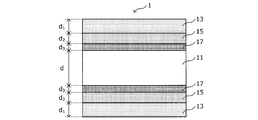
- FIG. 1 is an explanatory view schematically showing an example of the structure of the grain-oriented electrical steel sheet according to the present embodiment.
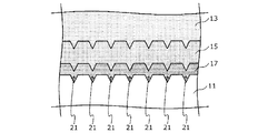
- FIG. 2 is an explanatory diagram for explaining the grain-oriented electrical steel sheet according to the present embodiment.
- the present inventors (1) significantly reduce iron loss to a high magnetic field iron loss of, for example, 1.7 T to 1.9 T when an inorganic coating such as forsterite (Mg 2 SiO 4 ) is removed.
- an inorganic coating such as forsterite (Mg 2 SiO 4 ) is removed.
- a tension-imparting insulating coating that exhibits a high tension of 1.0 kgf/mm 2 or more on a steel sheet surface without an inorganic coating with good adhesion, a silica-containing oxide layer and a silica-containing oxide layer are formed on the steel sheet surface. It is necessary to sequentially form the iron-based oxide layer, and by forming the silica-containing oxide layer and the iron-based oxide layer, the adhesion of the tension-imparting insulating coating and the high magnetic field iron loss are good.
- the present inventors have arrived at the grain-oriented electrical steel sheet according to the present embodiment based on the above findings.
- the grain-oriented electrical steel sheet 1 is a grain-oriented electrical steel sheet that does not have an inorganic coating mainly composed of forsterite, and as shown schematically in FIG.
- Base material steel plate 11 A silica-containing oxide layer 17 provided on the base steel sheet; An iron-based oxide layer 15 provided on the silica-containing oxide layer; A tension-imparting insulating coating 13 provided on the iron-based oxide layer, having a thickness of 1 to 3 ⁇ m, and containing phosphate and colloidal silica as main components; Equipped with.
- the silica-containing oxide layer 17, the iron-based oxide layer 15, and the tension-imparting insulating coating 13 are provided on both sides of the base steel plate 11, as schematically shown in FIG. Although FIG.
- the silica-containing oxide layer 17, the iron-based oxide layer 15, and the tension-imparting insulating coating 13 are provided on both surfaces of the base material steel sheet 11, the silica-containing oxide layer is illustrated.
- the iron-based oxide layer 15 and the tension-imparting insulating coating 13 may be provided only on one surface of the base steel plate 11 in some cases.
- the base material steel sheet 11 of the grain-oriented electrical steel sheet 1 according to the present embodiment, the tension-imparting insulating coating 13 (hereinafter sometimes simply referred to as "insulating coating"), the iron-based oxide layer 15, and the silica.
- the contained oxide layer 17 will be described in detail.
- grain-oriented electrical steel sheets contain silicon (Si) as a chemical component, but since silicon is extremely susceptible to oxidation, the surface of the steel sheet after decarburization annealing has an oxide film containing silicon (more specifically, Forms an oxide film containing silica as a main component. After applying an annealing separator to the surface of the steel sheet after decarburization annealing, the steel sheet is wound into a coil and finish annealing is performed.
- an annealing separator containing MgO as a main component is used, so that during the finish annealing, MgO reacts with the oxide film on the steel sheet surface, and forsterite (Mg 2 SiO 2 4 ) As a main component, an inorganic coating film is formed.
- the grain-oriented electrical steel sheet 1 according to this embodiment the grain-oriented electrical steel sheet having the forsterite as the main component is not the grain-oriented electrical steel sheet having the inorganic coating having the forsterite as the main component on the surface as described above.
- the grain-oriented electrical steel sheet not having on the surface is used as the base material steel sheet 11.
- the grain-oriented electrical steel sheet used as the base material steel sheet 11 is not particularly limited, and a grain-oriented electrical steel sheet having a known chemical component can be used. is there.
- a grain-oriented electrical steel sheet for example, as chemical components, in mass%, Si is 2.5 to 4.5%, Mn is 0.05 to 1.00%, Al is 0% or more and 0.05 or more. %, C is 0% or more and less than 0.1%, N is 0% or more and less than 0.05%, S is 0% or more and less than 0.1%, Se is 0% or more and less than 0.05%.
- the Si content in the base steel sheet By setting the Si content in the base steel sheet to be 2.5 mass% or more, desired magnetic properties can be obtained. On the other hand, when the Si content in the base steel sheet is more than 4.5% by mass, the steel sheet becomes brittle, which makes production difficult. Therefore, the Si content in the base steel sheet is 4.5 mass% or less.
- the Mn content in the base steel sheet By setting the Mn content in the base steel sheet to be 0.05 mass% or more, it becomes possible to secure the absolute amount of MnS, which is an inhibitor necessary for causing secondary recrystallization.
- the Mn content in the base steel sheet exceeds 1.00 mass %, the steel undergoes a phase transformation in the secondary recrystallization annealing, the secondary recrystallization does not proceed sufficiently, and a good magnetic flux density is obtained. Iron loss characteristics cannot be obtained. Therefore, the Mn content in the base steel sheet is 1.00 mass% or less.
- the base material steel sheet is, in addition to Si and Mn, Al as chemical components less than 0.05 mass%, C less than 0.1 mass%, N less than 0.05 mass% and S less than 0.1 mass%.
- Se may be contained in an amount of less than 0.05% by mass
- Bi may be contained in an amount of less than 0.01% by mass. Since these elements may not be contained, the lower limit value is 0% by mass.
- the N content in the base steel sheet By setting the N content in the base steel sheet to more than 0% by mass and less than 0.05% by mass, it becomes possible to suppress deterioration of stripability during manufacturing.
- the S content in the base steel sheet By setting the S content in the base steel sheet to more than 0 mass% and less than 0.1 mass%, it becomes possible to suppress embrittlement of the steel sheet.
- the Se content in the base steel sheet By setting the Se content in the base steel sheet to be 0% by mass or more and less than 0.05% by mass, the effect of improving magnetism can be realized.
- the Bi content in the base steel sheet By setting the Bi content in the base steel sheet to 0% by mass or more and less than 0.01% by mass, good magnetic flux density and iron loss characteristics can be realized.
- a fine structure 21 also called an etch pit is provided, as schematically shown in FIG.
- the fine structure 21 is a grain-oriented electrical steel sheet after finish annealing that does not have an inorganic coating for the first treatment liquid containing a specific acid in the method for producing a grain-oriented electrical steel sheet according to this embodiment described in detail below. It is formed by acting on the surface of.
- the silica-containing oxide layer 17 and the iron-based oxide layer 15 formed on the surface of the base material steel plate 11 by providing the fine structure 21 as schematically shown in FIG. 2 on the surface of the base material steel plate 11. Due to the so-called anchor effect, the adhesion with the base material steel plate 11 is further improved.
- the surface of the grain-oriented electrical steel sheet 1 according to this embodiment is provided with a tension-imparting insulating coating 13.
- the tension imparting insulating coating 13 reduces the eddy current loss by imparting electrical insulation to the grain-oriented electrical steel sheet, and reduces the iron loss of the grain-oriented electrical steel sheet. Further, the tension-imparting insulating coating 13 exhibits various characteristics such as corrosion resistance, heat resistance, and slipperiness, in addition to the above-described electric insulation.
- the tension-imparting insulating coating 13 has a function of imparting tension to the grain-oriented electrical steel sheet.
- the tension imparting insulating coating 13 can reduce the iron loss of the grain-oriented electrical steel sheet by applying tension to the grain-oriented electrical steel sheet to facilitate the domain wall movement in the grain-oriented electrical steel sheet.
- the tension-imparting insulating coating 13 is a phosphate-silica mixed system tension-imparting insulating coating containing phosphate and colloidal silica as main components.
- the tension-imparting insulating coating of such a phosphate-silica mixed system contains, for example, 25 to 45 mass% of colloidal silica, and the balance is aluminum phosphate, magnesium phosphate, zinc phosphate, manganese phosphate, cobalt phosphate, Also, it is preferable to have one or more selected from the group consisting of iron phosphate as a main component.
- the thickness (thickness d 1 in FIG. 1 ) of the tension-giving insulating coating 13 of the phosphate-silica mixed system is in the range of 1 to 3 ⁇ m. If the thickness of the tension-imparting insulating coating 13 is less than 1 ⁇ m, it is impossible to sufficiently improve various properties such as the above-described electric insulation, corrosion resistance, heat resistance, slipperiness, and tension imparting property. On the other hand, when the thickness of the tension-imparting insulating coating 13 exceeds 3 ⁇ m, the space factor of the base steel sheet 11 decreases, which is not preferable.
- the thickness of the tension imparting insulating coating 13 By setting the thickness of the tension imparting insulating coating 13 to be in the range of 1 to 3 ⁇ m, a high tension of 1.0 kgf/mm 2 or more can be realized.
- the thickness d 1 of the tension imparting insulating coating 13 is preferably in the range of 2.5 to 3.0 ⁇ m.
- the iron-based oxide layer 15 functions as an intermediate layer between the base material steel plate 11 and the tension-imparting insulating coating 13 together with the silica-containing oxide layer 17 described later in the grain-oriented electrical steel sheet 1 according to the present embodiment. ..
- the iron-based oxide layer 15 contains an iron-based oxide such as magnetite (Fe 3 O 4 ), hematite (Fe 2 O 3 ), or firelite (Fe 2 SiO 4 ) as a main component.
- the iron-based oxide that is the main component of the iron-based oxide layer 15 is formed by the reaction of the surface of the base material steel plate 11 with oxygen, the iron-based oxide between the iron-based oxide layer 15 and the base material steel plate 11 is formed. Has good adhesion.
- the fine structure 21 also called an etch pit, which is schematically shown in FIG. 2, is provided on the surface of the base material steel plate 11. Therefore, the iron-based oxide layer 15 formed in the fine structure 21 can further improve the adhesion with the base material steel plate 11 by the so-called anchor effect together with the silica-containing oxide layer 17 described later.
- the grain-oriented electrical steel sheet 1 since the iron-based oxide layer 15 is provided between the base material steel sheet 11 and the tension-imparting insulating coating 13 which is a kind of ceramics, the base material Although the inorganic coating is not formed on the surface of the steel sheet 11, the adhesion of the tension imparting insulating coating 13 can be improved.
- the surface of the iron-based oxide layer 15 is also subjected to pickling treatment using the second treatment liquid to obtain a fine structure as shown in FIG. Is formed. Therefore, the adhesion between the iron-based oxide layer 15 and the tension-imparting insulating coating 13 can be further improved.
- the iron-based oxide layer 15 preferably has a thickness (thickness d 2 in FIG. 1) within a range of 100 to 500 nm.
- the thickness d 2 of the iron-based oxide layer 15 is less than 100 nm, the iron-based oxide layer 15 and the silica-containing oxide layer 17 are dissolved by the acidic treatment liquid used when forming the tension imparting insulating coating 13. Therefore, there is a high possibility that sufficient adhesion cannot be obtained.
- the thickness d 2 of the iron-based oxide layer 15 exceeds 500 nm, the iron-based oxide layer 15 becomes too thick and is likely to be partially peeled.
- the thickness d 2 of the iron-based oxide layer 15 is preferably in the range of 150 to 400 nm, more preferably 170 to 250 nm.
- the thickness d 2 of the iron-based oxide layer 15 is, for example, using X-ray Photoelectron Spectroscopy (XPS), and the cross-section of the grain-oriented electrical steel sheet 1 according to the present embodiment has an iron-oxygen bond It can be specified by observing the distribution. That is, from the surface side of the grain-oriented electrical steel sheet 1 from which the tension imparting insulating coating 13 is removed, focusing on the intensity of the Fe—O peak appearing at 712 eV and the intensity of the metallic Fe peak appearing at 708 eV by XPS.
- XPS X-ray Photoelectron Spectroscopy
- the main component of the iron-based oxide layer 15 can be identified by performing analysis by X-ray crystal structure analysis method or XPS. From the measurement results obtained so far by the present inventors, it has been found that the iron-based oxide layer 15 mainly contains iron oxide as a main component and contains a small amount of silica.
- the silica-containing oxide layer 17 functions as an intermediate layer between the base steel sheet 11 and the tension-imparting insulating coating 13 together with the iron-based oxide layer 15 in the grain-oriented electrical steel sheet 1 according to the present embodiment. It is a layer.
- the silica-containing oxide layer 17 contains silica and firelite (Fe 2 SiO 4 ) as main components.
- the present inventors performed a more detailed verification of the adhesion of the tension-imparting insulating coating in the grain-oriented electrical steel sheet having a microstructure formed on the surface of the base steel sheet, and under certain manufacturing conditions, , It was found that there were some areas with good adhesion and some areas with poor adhesion.
- silica and firelight originated from Si diffused from the base material steel plate to the lower layer side (base material steel sheet side) of the iron-based oxide layer ( While a silica-containing oxide layer containing Fe 2 SiO 4 ) as a main component is formed, an iron-based oxide layer or a silica-containing oxide layer is present in a portion where adhesion is not good. Turned out not to.
- One of the reasons why the part where the iron-based oxide layer or the silica-containing oxide layer does not exist is the small amount of the iron-based oxide layer or the silica-containing oxide layer (in other words, the thickness is thin). It is possible.
- the treatment liquid used to form the tension-imparting insulating coating is acidic, the thin iron-based oxide layer and the silica-containing oxide layer were dissolved during the formation of the tension-imparting insulating coating, and the effect of improving adhesion was reduced. Presumed to be. Another possibility is that the iron-based oxide layer was excessively formed. When the iron-based oxide layer is excessively generated, iron oxide (smudge) liberated from the surface is generated, so it is speculated that the treatment liquid used to form the tension-imparting insulating coating did not adhere to the steel plate surface. It
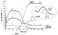
- FIG. 3A shows an example of the GDS analysis result of a grain-oriented electrical steel sheet with good adhesion
- FIG. 3B shows an example of the GDS analysis result of a grain-oriented electrical steel sheet with poor adhesion.
- the tension-imparting insulating coating is formed using a treatment liquid containing colloidal silica and aluminum phosphate.
- the horizontal axis represents the elapsed time [seconds] from the start of analysis
- the vertical axis represents the GDS relative intensity [a. u. ].
- GDS is a method of analyzing the surface of a sample toward a deep portion in the thickness direction while sputtering, the longer the elapsed time, the more the deep portion of the sample is analyzed. Further, in FIGS. 3A and 3B, for the elements other than Fe, the obtained results are magnified three times and displayed in the figures.
- an emission peak derived from Al and an emission peak derived from Si are observed in a region where the elapsed time is about 0 to 40 seconds.
- the GDS relative intensity derived from P is slightly attenuated after about 5 seconds and then is gradually attenuated, and it seems that there is an emission peak derived from P that is gently and broadly distributed.
- These peaks are derived from the tension-imparting insulating coating 13 because they contain Al, Si, and P.
- the emission peak derived from Fe increases as the elapsed time becomes longer, it is understood that the iron-based oxide layer is formed.
- the emission peak derived from Al and the emission peak derived from P are monotonically decreased, whereas the second one derived from Si is monotonically decreased.
- the emission peak (hereinafter, may be referred to as peak A) is observed in a region A surrounded by a broken line in FIG. 3A.
- the second emission peak (peak A) is the emission peak intensity derived from Fe from the inflection point (in the case of FIG. 3A, the position where the elapsed time is about 40 seconds) at which the increase rate of the emission peak intensity derived from Fe changes. Exists until the point at which is saturated (in the case of FIG.
- the second emission peak (peak A) derived from Si was observed in any of the grain-oriented electrical steel sheets having good adhesion, although the elapsed time at which the peak was observed was different. Therefore, it is understood that the second emission peak (peak A) is derived from the silica-containing oxide layer containing silica and firelite (Fe 2 SiO 4 ) as main components.
- the second Si is the Si emission intensity in the steel (that is, the spatter progresses to the base steel sheet, and the intensity of the emission peak derived from Si is steady. It was revealed that the emission intensity was 0.30 times or more and 2.5 times or less than the emission intensity of the part in the state. On the contrary, when the peak height of the peak A is less than 0.30 times the Si emission intensity in the base material steel sheet or exceeds 2.5 times, the tension-imparting insulating coating film has poor adhesion. It turned out to be inferior.
- the portion where the Si element is segregated at a certain depth position of the grain-oriented electrical steel sheet is the silica-containing oxide layer 17 in the present embodiment, and the portion corresponding to the silica-containing oxide layer 17. It has been revealed that when the Si element in (region A in FIG. 3A) has a specific concentration (0.30 times to 2.5 times the Si emission intensity in steel), good adhesion is exhibited. .. Since the segregated portion of the Si element is derived from Si diffused from the base steel sheet, the segregated portion of the Si element exists at a position close to the base steel sheet.
- the second peak derived from Si as described above is slightly observed, but the height of such peak is It can be seen that the emission intensity of Si in steel is not more than 0.30 times and not more than 2.5 times.
- the second peak derived from Si may not be observed.
- the GDS analysis result as shown in FIG. 3A shows the average behavior of each element in the region of the sample having a diameter of about 5 mm. Can be thought of as observing. Therefore, in the coil in which the grain-oriented electrical steel sheet is wound, when the GDS analysis result of the arbitrary region at the position separated by the arbitrary distance from the coil head shows the behavior as shown in FIG. 3A, It is considered that the portions having the same distance from the head of the mouse show the same GDS analysis result as that shown in FIG. 3A. Further, if the GDS analysis result shows the behavior shown in FIG. 3A in both the head and the tail of the coil, the GDS analysis result shows the behavior shown in FIG. 3A in the entire coil. Can be considered.
- elemental analysis is performed by the glow discharge emission spectrometry (GDS) from the surface of the grain-oriented electrical steel sheet 1 in the thickness direction of the grain-oriented electrical steel sheet 1.
- GDS glow discharge emission spectrometry
- peak A which is the peak of the Si light emission intensity closest to the base material steel plate side, changes in the increase rate of the Fe light emission intensity along the plate thickness direction from the surface of the tension imparting insulating coating. It exists between the inflection point and the saturation point where the Fe emission intensity is saturated.
- peak height of the peak A is the Si emission in the base material steel plate when the length of the perpendicular line when the perpendicular line is drawn from the top of the peak to the valley connecting the peaks is the peak height. The strength is 0.30 times or more and 2.5 times or less.
- the reason why the number of Si emission intensity peaks is two or more under the above condition (a) is as follows.
- a shoulder overlapping of peaks
- the tension-imparting insulating coating may be formed a plurality of times while changing the Si concentration of the treatment liquid in order to impart stronger tension.
- the silica-containing oxide layer 17 is formed when a heat treatment is performed at a predetermined temperature after performing a pickling treatment for forming the fine structure 21 on the surface of the base steel sheet 11 using the first treatment liquid.
- the conditions for performing depth direction analysis by GDS from the surface of grain-oriented electrical steel sheet are as follows.
- the depth direction analysis by GDS under the following conditions, it is possible to obtain the GDS analysis result as shown in FIG. 3A in the grain-oriented electrical steel sheet having excellent adhesion. That is, in a high frequency mode of a general glow discharge emission spectroscopic analyzer (for example, GDA750 manufactured by Rigaku Corporation), the output is 30 W, the Ar pressure is 3 hPa, the measurement area is 4 mm ⁇ , and the measurement time is 100 seconds.
- the GDS analysis result as shown in FIG. 3A can be obtained.
- the thickness of the silica-containing oxide layer 17 (thickness d 3 in FIG. 1) is often 100 nm or less, and may be about 20 to 30 nm.
- the thickness of the silica-containing oxide layer 17 can be calculated from the sputtering rate in GDS and the elapsed time width in which the second peak derived from Si is observed, as shown in the region A of FIG. 3A. it can.
- the main component of the silica-containing oxide layer 17 can be identified by performing analysis by X-ray crystal structure analysis method or XPS.
- the thickness of the base material steel sheet 11 is not particularly limited and may be 0.27 mm or less, for example.
- the thinner the steel sheet the lower the adhesion of the tension-imparting insulating coating is in many cases.
- the iron-based oxide layer 15 and the silica-containing oxide layer 17 are provided, so that the tension imparting property is obtained even when the thickness d is 0.27 mm or less.
- the excellent adhesion of the insulating coating 13 can be obtained.
- the base material steel sheet 11 preferably has a thickness d within a range of 0.17 to 0.23 mm.
- the thickness d of the base steel plate 11 in the grain-oriented electrical steel plate 1 according to this embodiment is not limited to the above range.
- the grain-oriented electrical steel sheet according to the present embodiment does not have an inorganic coating mainly composed of forsterite. It is judged by the following analysis that "the inorganic coating film containing forsterite as a main component is not formed".
- an EDS Energy Dispersive X-ray Spectroscopy
- SEM Sccanning Electron Microscope
- TEM Transmission Electron Microscope
- the base material steel plate is a layered region existing at the deepest position in the plate thickness direction, and a region where the Fe content is 80 atomic% or more and the O content is less than 30 atomic% excluding measurement noise. To judge.
- tension is applied to the region where the Fe content is less than 80 atomic%, the P content is 5 atomic% or more, and the O content is 30 atomic% or more, excluding the measurement noise. It is judged to be a conductive insulating film.
- the area excluding the base steel sheet and the tension-imparting insulating coating specified above is judged to be the intermediate layer consisting of the silica-containing oxide layer and the iron-based oxide layer.
- the intermediate layer has an average Fe content of less than 80 atom% on average, a P content of less than 5 atom% on average, a Si content of 20 atom% or more on average, and an O content of 30 atom on average. % Or more should be satisfied.
- the average content of Mg in the intermediate layer may be less than 20 atomic %.
- the Mg content of the intermediate layer is preferably 10 atom% or less, more preferably 5 atom% or less, and further preferably 3 atom% or less.
- the grain-oriented electrical steel sheet according to the present embodiment has the iron-based oxide layer 15 and the silica-containing oxide layer 17 between the base material steel sheet 11 and the tension imparting insulating coating 13, It is possible to further improve the adhesiveness of the tension-imparting insulating coating 13, and it is also possible to significantly reduce the high magnetic field iron loss of, for example, 1.7 T to 1.9 T.
- Various magnetic characteristics such as magnetic flux density and iron loss of the grain-oriented electrical steel sheet according to the present embodiment are determined by the Epstein method defined by JIS C2550 and the single sheet magnetic characteristic measurement method (Single Sheet Tester defined by JIS C2556). : SST) can be measured.
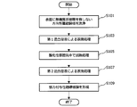
- FIG. 4 is a flow chart showing an example of the flow of the method for manufacturing a grain-oriented electrical steel sheet according to this embodiment.
- the grain-oriented electrical steel sheet having no inorganic coating mainly composed of forsterite on the surface (more specifically, forsterite on the surface.
- the method for obtaining the grain-oriented electrical steel sheet having no inorganic coating is not particularly limited.
- Si is 2.5 to 4.5%
- Mn is 0.05 to 1.00%
- Al is 0.05% or less
- C is 0.1% or less
- N is Hot rolling step of hot rolling a steel slab containing 0.05% or less, S 0.1% or less, Se 0.05% or less and Bi 0.01% or less, and the balance being Fe and impurities.
- a method including an optional annealing step, a cold rolling step of performing one cold rolling or two or more cold rolling steps sandwiching an intermediate annealing, a decarburizing annealing step, and a finish annealing step. ..
- an inorganic coating for example, a method of applying an annealing separator that does not form an inorganic coating and performing finish annealing, or performing finish annealing using a commonly used annealing separator. After that, a method of removing the produced inorganic coating by a known method such as grinding or pickling may be used.
- the method of performing finish annealing using an annealing separator that does not form an inorganic coating is preferable because it is easier to control and the steel sheet surface condition is better.
- an annealing separator for example, an annealing separator containing a mixture of MgO and Al 2 O 3 with bismuth chloride, or a mixture of MgO and Al 2 O 3 containing a bismuth compound and a chlorine compound of a metal. It is preferable to use the above-mentioned annealing separator.
- Examples of the bismuth chloride include bismuth oxychloride (BiOCl) and bismuth trichloride (BiCl 3 ).
- Examples of the bismuth compound include bismuth oxide, bismuth hydroxide, bismuth sulfide, bismuth sulfate, bismuth phosphate, bismuth carbonate, bismuth nitrate, bismuth organic acid, bismuth halide, and the like, metal chlorine compounds Examples thereof include iron chloride, cobalt chloride, nickel chloride and the like.
- the content of the bismuth chloride or the chlorinated metal of the bismuth compound and the metal is not particularly limited, but is about 3 to 15 parts by mass with respect to 100 parts by mass of the mixture of MgO and Al 2 O 3. It is preferable.
- the method for manufacturing a grain-oriented electrical steel sheet according to the present embodiment uses a grain-oriented electrical steel sheet after finish annealing that does not have an inorganic coating and removes excess annealing separator by washing.
- a surface treatment is performed by causing a specific concentration of acid (first treatment liquid) to act on the surface of the steel sheet (step S103, first surface treatment step), at a specific temperature in an oxidizing atmosphere.
- a heat treatment is performed (step S105, heat treatment step), and a surface treatment is performed by causing an acid (second treatment liquid) having a specific concentration to act on the steel sheet surface after the heat treatment (step S107, second surface treatment step).
- the intermediate layer mainly composed of the iron-based oxide layer and the silica-containing oxide layer as described above is formed on the surface of the grain-oriented electrical steel sheet having no inorganic coating film after finish annealing.
- a tension-imparting insulating coating is formed on the grain-oriented electrical steel sheet having the iron-based oxide layer and the silica-containing oxide layer formed thereon with good adhesion (step S109, tension-imparting insulating coating forming step).
- the first treatment liquid used in the first surface treatment step of step S103 contains one or more of sulfuric acid, nitric acid, and phosphoric acid, and the total acid concentration is 2 to 20% by mass.
- the temperature is 70-90°C.
- the liquid temperature of the first treatment liquid is lower than 70° C.
- the solubility of the first treatment liquid is lowered, the possibility of forming a precipitate is increased, and an effective etch pit is obtained. Can not.
- the liquid temperature of the first treatment liquid exceeds 90° C., the reactivity of the first treatment liquid becomes too high and the steel sheet surface is excessively etched during the first surface treatment step, which is not preferable.
- the liquid temperature of the first treatment liquid is preferably in the range of 75 to 87°C, more preferably in the range of 80 to 85°C.
- the total acid concentration of the first treatment liquid is preferably in the range of 2 to 17% by mass, more preferably 2 to 10% by mass.
- the treatment time of the first surface treatment step is not particularly limited.
- the first surface treatment step is often performed by continuously immersing the steel plate in a treatment bath in which the first treatment liquid is held.
- the time taken for the steel sheet to pass through the treatment bath is the treatment time of the first surface treatment step.
- the active surface state as described above can be realized by dipping and passing the steel plate in the treatment bath at a general passing speed.
- the oxygen concentration is 1 to 21% by volume and the dew point is -20 to In an atmosphere of 30° C., heating is performed for 10 to 60 seconds so that the steel sheet temperature is 700 to 900° C. (heat treatment step).
- the oxygen concentration in the atmosphere is preferably in the range of 2 to 21% by volume, more preferably 15 to 21% by volume.
- the dew point in the atmosphere is preferably in the range of -10 to 25°C, more preferably in the range of -10 to 20°C.
- the heating temperature of the steel sheet in the heat treatment step is less than 700° C., it becomes difficult to form the iron-based oxide layer and the silica-containing oxide layer in an appropriate state even if the heating time is 60 seconds, which is preferable. Absent. On the other hand, if the heating temperature of the steel sheet exceeds 900° C., the iron-based oxide layer tends to be non-uniform, and the silica-containing oxide layer in a desired state cannot be formed, which is not preferable.
- the heating temperature of the steel sheet in the heat treatment step is preferably in the range of 750 to 800°C.
- the heating time is less than 10 seconds, the generated iron-based oxide layer and silica-containing oxide layer are likely to be non-uniform, which is not preferable. On the other hand, if the heating time exceeds 60 seconds, the cost becomes industrially high, which is not preferable.
- the heating time is preferably in the range of 20 to 30 seconds.
- the activated surface of the grain-oriented electrical steel sheet having no inorganic coating is oxidized and the iron having a coefficient of thermal expansion located between the metal and the insulating coating.
- the system-containing oxide layer is formed, and the silica-containing oxide layer is formed by Si diffused from the base steel sheet.
- the iron-based oxide layer having an etch pit formed on the surface of the grain-oriented electrical steel sheet and having a preferable coefficient of thermal expansion, and the silica-containing oxide layer in a preferable segregation state are formed to reduce strain.
- the adhesion of the tension-imparting insulating coating can be further improved, and the effect of improving the high magnetic field iron loss can be exhibited.
- the second treatment liquid used in the second surface treatment step of step S107 contains one or more of sulfuric acid, nitric acid, and phosphoric acid, and the total acid concentration is 1 to 10 mass %.
- the liquid temperature of the second treatment liquid is preferably 50° C. or higher and 90° C. or lower.
- the solubility of the second treatment liquid is lowered, the possibility of forming a precipitate is increased, and an effective etch pit is obtained. It may not be possible.
- the liquid temperature of the second treatment liquid exceeds 90° C., the reactivity of the second treatment liquid becomes too high and the iron-based oxide layer and the silica-containing oxide layer may be dissolved.
- the liquid temperature of the second treatment liquid is preferably in the range of 70 to 85°C, more preferably in the range of 80 to 85°C.
- the total acid concentration of the second treatment liquid is preferably in the range of 1 to 5% by mass, more preferably 1 to 3% by mass.
- the processing time of the second surface treatment step is 1 second or more and 10 seconds or less. If the processing time is less than 1 second, etch pits cannot be properly formed on the surface of the iron-based oxide layer. On the other hand, when the treatment time exceeds 10 seconds, the surface of the steel sheet is excessively etched during the second surface treatment step, which is not preferable.
- the treatment time of the second surface treatment step is preferably in the range of 2 to 8 seconds, more preferably 2 to 5 seconds.
- the step of forming the tension-imparting insulating coating is not particularly limited, and a known insulating coating treatment liquid of a phosphate silica mixed system as described below.
- the insulating coating solution may be applied and dried by using a known method.
- the surface of the steel sheet on which the tension-imparting insulating coating is formed may be subjected to any pretreatment such as degreasing treatment with an alkali or the like before applying the insulating coating treatment liquid. It may be the surface.
- the tension-imparting insulating coating formed on the surface of the steel sheet is not particularly limited as long as it is used as the tension-imparting insulating coating of the phosphate-silica mixed system of the grain-oriented electrical steel sheet. It is possible to use a tension-imparting insulating coating of silica salt mixed system. Examples of such a tension-imparting insulating coating include a coating containing phosphate and colloidal silica as main components. As another example, there may be mentioned a composite insulating coating containing phosphate and colloidal silica as main components and fine organic resin particles dispersed therein.
- colloidal silica is contained in an amount of 25 to 45 mass% with respect to the total solid content, and the remaining solid content is aluminum phosphate, magnesium phosphate, zinc phosphate, An insulating coating solution containing, as a main component, one or more selected from the group consisting of manganese phosphate, cobalt phosphate, and iron phosphate is prepared.
- the pH of the insulating coating liquid it is preferable to adjust the pH of the insulating coating liquid so that it falls within the range of 1.2 to 3.4.
- the tension-imparting insulating coating can be formed in a more suitable state.
- the adjusted insulating coating solution is applied to the surface of the grain-oriented electrical steel sheet by a known method so that the thickness after drying becomes 1 to 3 ⁇ m, and drying and baking are performed.
- the time between the first surface treatment step and the heat treatment step, and the time between the second surface treatment step and the tension-imparting insulating coating forming step are preferably as short as possible, for example, within several minutes. preferable.
- flattening annealing for shape correction may be performed.
- the iron loss can be further reduced.
- the following is a specific description of the grain-oriented electrical steel sheet and the method for producing the grain-oriented electrical steel sheet according to the present invention, showing examples and comparative examples.
- the examples shown below are merely examples of the method for producing a grain-oriented electrical steel sheet and a grain-oriented electrical steel sheet according to the present invention, and the method for producing a grain-oriented electrical steel sheet and a grain-oriented electrical steel sheet according to the present invention.
- the examples are not limited to the following.
- an annealing separator containing MgO and Al 2 O 3 as main components and containing BiOCl, which is a bismuth chloride, in an amount of 10 mass% was applied and dried, and finish annealing was performed at a steel plate temperature of 1200° C. for 20 hours (finish annealing under such conditions). Was also called "purification annealing".).
- finish annealing was performed at a steel plate temperature of 1200° C. for 20 hours (finish annealing under such conditions).
- the sheet was washed with water to remove the excess annealing separator, and no inorganic coating was formed on the surface of the steel sheet.
- the Al content is less than 0.05%
- the C content is less than 0.1%
- the N content is less than 0.05%
- the S content is 0.1%.
- the content of Se was less than 0.05%
- the content of Bi was less than 0.01%.
- the first surface treatment step was performed under the conditions shown in Table 1
- the heat treatment step was performed under the conditions shown in Table 1
- the second surface treatment step was performed under the conditions shown in Table 1. ..
- aluminum phosphate content: 60% by mass based on total solid content
- silica colloidal silica, average particle size is 20 nm (catalog value), content is 40% by mass based on total solid content
- the chemicals used in the first treatment liquid and the second treatment liquid were all commercially available general-grade reagents, and the commercially available general-grade reagents were also used for aluminum phosphate and colloidal silica.
- XPS PHI5600 manufactured by ULVAC-PHI, Inc.
- the main component of the iron-based oxide layer was identified by the crystal structure analysis method.
- GDS Low Discharge Optical Emission Spectrometer GDA750 manufactured by Rigaku
- XPS measurement conditions X-ray source: MgK ⁇ Analysis area: approx. 800 ⁇ m ⁇ Depth direction analysis (sputtering yield: 2 nm/min in terms of SiO 2 ) Measuring elements: C, O, Al, Si, Fe Measurement surface: outermost surface, 0.1, 0.5, 1, 2, 5, 10, 20, 30, 40, 50, 60, 70, 80, 90, 100 minutes after sputtering
- GDS measurement condition High frequency mode Output: 30W Ar pressure: 3 hPa Measurement area: 4 mm ⁇ Measuring time: 100 seconds Measuring element: O, Al, Si, P, Fe
- the peak of Si emission intensity existing closest to the base material steel sheet is Fe emission from the surface of the grain-oriented electrical steel sheet along the plate thickness direction. It shows whether or not there exists between the position of the inflection point where the rate of increase in intensity changes and the saturation point where the Fe emission intensity is saturated.
- the score "A” indicates that the peak of the Si emission intensity that is most present on the base material steel plate side exists between the position of the inflection point and the saturation point, and the score "B” is the most base material steel plate side. It is shown that the peak of the Si emission intensity existing in 1) does not exist between the position of the inflection point and the saturation point.
- the adhesion of the tension-imparting insulating coating was evaluated as follows. First, a sample with a width of 30 mm and a length of 300 mm is taken from each grain-oriented electrical steel sheet, subjected to strain relief annealing at 800° C. for 2 hours in a nitrogen stream, and subjected to a bending adhesion test using a 10 mm ⁇ cylinder to apply tension. The evaluation was performed according to the degree of peeling of the conductive insulating coating. The evaluation criteria are as follows, and the score A and the score B were passed. Rating A: No peeling B: Almost no peeling C: Peeling of several mm is seen D: Peeling of 1/3 to 1/2 is seen E: Full peeling
- the iron-based oxide layer of the sample corresponding to the example of the present invention contains magnetite, hematite, and firelite as main components, and the silica-containing oxide layer is , Silica and firelite were the main components.
- magnetite, hematite, and, although the iron-based oxide layer containing firelite as a main component was formed, a predetermined number of peaks, and a predetermined peak height No silica-containing oxide layer was formed.
- a sample was prepared from the grain-oriented electrical steel sheet according to the example and analyzed by SEM-EDS. As a result, in the intermediate layers in the grain-oriented electrical steel sheets according to the examples, the Mg content was 20 atomic% or less, and the inorganic coating film containing forsterite as the main component was not formed.
Landscapes
- Chemical & Material Sciences (AREA)
- Engineering & Computer Science (AREA)
- Materials Engineering (AREA)
- Mechanical Engineering (AREA)
- Metallurgy (AREA)
- Organic Chemistry (AREA)
- Physics & Mathematics (AREA)
- Thermal Sciences (AREA)
- Crystallography & Structural Chemistry (AREA)
- Electromagnetism (AREA)
- Manufacturing & Machinery (AREA)
- Chemical Kinetics & Catalysis (AREA)
- General Chemical & Material Sciences (AREA)
- Health & Medical Sciences (AREA)
- General Physics & Mathematics (AREA)
- Nuclear Medicine, Radiotherapy & Molecular Imaging (AREA)
- Life Sciences & Earth Sciences (AREA)
- Analytical Chemistry (AREA)
- Biochemistry (AREA)
- General Health & Medical Sciences (AREA)
- Pathology (AREA)
- Immunology (AREA)
- Power Engineering (AREA)
- Dispersion Chemistry (AREA)
- Inorganic Chemistry (AREA)
- Chemical Treatment Of Metals (AREA)
- Manufacturing Of Steel Electrode Plates (AREA)
- Soft Magnetic Materials (AREA)
Abstract
Description
本願は、2019年1月16日に、日本に出願された特願2019-5238号に基づき優先権を主張し、その内容をここに援用する。
上記知見に基づき完成された本発明の要旨は、以下の通りである。
母材鋼板と;
前記母材鋼板上に設けられたシリカ含有酸化物層と;
前記シリカ含有酸化物層上に設けられた鉄系酸化物層と;
前記鉄系酸化物層上に設けられ、厚みが1~3μmであり、リン酸塩及びコロイダルシリカを主成分とする張力付与性絶縁被膜と;
を備え、
前記母材鋼板は、化学成分として、質量%で、Siを2.5~4.5%、Mnを0.05~1.00%、Alを0%以上かつ0.05%未満、Cを0%以上かつ0.1%未満、Nを0%以上かつ0.05%未満、Sを0%以上かつ0.1%未満、Seを0%以上かつ0.05%未満及びBiを0%以上かつ0.01%未満含有し、残部がFe及び不純物であり、
前記張力付与性絶縁被膜の表面から板厚方向にグロー放電発光分析法による元素分析を行ったときに、
(a)Si発光強度のピークが2つ以上存在し;
(b)前記板厚方向に関して、最も母材鋼板側に存在する前記Si発光強度のピークであるピークAが、前記張力付与性絶縁被膜の前記表面から前記板厚方向に沿ってFe発光強度の増加率が変化する変曲点と、前記Fe発光強度が飽和する飽和点と、の間に存在し;
(c)ピーク頭頂部から前記ピークに近接する谷部を結ぶベースラインに垂線を下したときの前記垂線の長さをピーク高さとしたとき、前記ピークAの前記ピーク高さが、前記母材鋼板中の前記Si発光強度の0.30倍以上2.5倍以下である。
[2][1]に記載の方向性電磁鋼板では、前記シリカ含有酸化物層が、シリカ及びファイアライトを主成分とし、
前記張力付与性絶縁被膜は、コロイダルシリカを25~45質量%含有し、残部がリン酸アルミニウム、リン酸マグネシウム、リン酸亜鉛、リン酸マンガン、リン酸コバルト、及び、リン酸鉄からなる群より選択される1種又は2種以上を主成分としてもよい。
[3][1]又は[2]に記載の方向性電磁鋼板では、前記鉄系酸化物層が、マグネタイト、ヘマタイト及びファイアライトを主成分としてもよい。
[4][1]~[3]の何れか1つに記載の方向性電磁鋼板では、前記母材鋼板の厚みが、0.27mm以下であってもよい。
[5]本発明の別の一態様に係る方向性電磁鋼板の製造方法は、母材鋼板と、張力付与性絶縁被膜と、を備え、フォルステライトを主成分とする無機質系被膜を有さない方向性電磁鋼板の製造方法であって、
前記方向性電磁鋼板の表面を洗浄する洗浄工程と;
硫酸、リン酸及び硝酸の1種又は2種以上を含有し、合計の酸濃度が2~20%であり、かつ、液温が70~90℃である第1処理液を用いて、前記洗浄工程後の前記方向性電磁鋼板の前記表面を処理する第1表面処理工程と;
前記第1表面処理工程後の前記方向性電磁鋼板を、酸素濃度が1~21体積%であり、露点が-20~30℃である雰囲気の下、700~900℃の温度に10~60秒間加熱する加熱処理工程と;
硫酸、リン酸及び硝酸の1種又は2種以上を含有し、合計の酸濃度が1~10%である第2処理液を用いて、前記加熱処理工程後の前記方向性電磁鋼板の前記表面を1~10秒間処理する第2表面処理工程と;
前記第2表面処理工程後の前記方向性電磁鋼板の前記表面に、厚みが1~3μmであり、リン酸塩及びコロイダルシリカを主成分とする張力付与性絶縁被膜を形成する張力付与性絶縁被膜形成工程と;
を有する。
[6][5]に記載の方向性電磁鋼板の絶縁被膜形成方法は、前記洗浄工程の前に、
化学成分として、質量%で、Siを2.5~4.5%、Mnを0.05~1.00%、Alを0.05%以下、Cを0.1%以下、Nを0.05%以下、Sを0.1%以下、Seを0.05%以下及びBiを0.01%以下含有し、残部がFe及び不純物である鋼片を熱間圧延する熱間圧延工程と;
任意の焼鈍工程と;
1回の冷間圧延又は中間焼鈍を挟む2回以上の冷間圧延を施す冷間圧延工程と;
脱炭焼鈍工程と;
MgOとAl2O3の混合物にビスマス塩化物を含有させた焼鈍分離剤、又は、MgOとAl2O3の混合物にビスマス化合物と金属の塩素化合物を含有させた焼鈍分離剤を塗布して乾燥させた後、仕上げ焼鈍を施す仕上げ焼鈍工程と;
を更に有してもよい。
まず、図1~図2を参照しながら、本発明の実施形態に係る方向性電磁鋼板について、詳細に説明する。図1は、本実施形態に係る方向性電磁鋼板の構造の一例を模式的に示した説明図である。図2は、本実施形態に係る方向性電磁鋼板について説明するための説明図である。
母材鋼板11と;
前記母材鋼板上に設けられたシリカ含有酸化物層17と;
前記シリカ含有酸化物層上に設けられた鉄系酸化物層15と;
前記鉄系酸化物層上に設けられ、厚みが1~3μmであり、リン酸塩及びコロイダルシリカを主成分とする張力付与性絶縁被膜13と;
を備える。
シリカ含有酸化物層17、鉄系酸化物層15及び張力付与性絶縁被膜13は、図1に模式的に示したように、母材鋼板11の両面上に設けられる。なお、図1では、シリカ含有酸化物層17、鉄系酸化物層15及び張力付与性絶縁被膜13が母材鋼板11の両面上に設けられる場合について図示しているが、シリカ含有酸化物層17、鉄系酸化物層15及び張力付与性絶縁被膜13は、母材鋼板11の一方の面上にのみ設けられる場合もある。
一般に、方向性電磁鋼板には、化学成分としてケイ素(Si)が含有されるが、ケイ素は極めて酸化されやすいため、脱炭焼鈍後の鋼板表面には、ケイ素を含有する酸化被膜(より詳細には、シリカを主成分とする酸化被膜)が形成される。脱炭焼鈍後の鋼板表面に対し焼鈍分離剤を塗布した後、鋼板をコイル状に巻き取り、仕上げ焼鈍が行われる。通常の方向性電磁鋼板の製造方法では、MgOを主成分とする焼鈍分離剤が用いられることで、仕上げ焼鈍中に、MgOと鋼板表面の酸化被膜とが反応して、フォルステライト(Mg2SiO4)を主成分とする無機質系被膜が形成される。しかしながら、本実施形態に係る方向性電磁鋼板1では、上記のようなフォルステライトを主成分とする無機質系被膜を表面に有する方向性電磁鋼板ではなく、フォルステライトを主成分とする無機質系被膜を表面に有しない方向性電磁鋼板が、母材鋼板11として用いられる。
母材鋼板中のAl含有量を0質量%超0.05質量%未満とすることで、鋼板の脆化を抑制しつつ、鉄損特性を改善することが可能となる。
母材鋼板中のC含有量を0質量%超0.1質量%未満とすることで、良好な磁束密度及び鉄損特性を実現することが可能となる。
母材鋼板中のN含有量を0質量%超0.05質量%未満とすることで、製造時の通板性の低下を抑制することが可能となる。
母材鋼板中のS含有量を0質量%超0.1質量%未満とすることで、鋼板の脆化を抑制することが可能となる。
母材鋼板中のSe含有量を0質量%以上0.05質量%未満とすることで、磁性改善効果を実現することができる。
母材鋼板中のBi含有量を0質量%以上0.01質量%未満とすることで、良好な磁束密度及び鉄損特性を実現することができる。
本実施形態に係る方向性電磁鋼板1の表面には、張力付与性絶縁被膜13が設けられている。張力付与性絶縁被膜13は、方向性電磁鋼板に電気絶縁性を付与することで渦電流損を低減して、方向性電磁鋼板の鉄損を低減する。また、張力付与性絶縁被膜13は、上記のような電気絶縁性以外にも、耐蝕性、耐熱性、すべり性といった種々の特性を奏する。
鉄系酸化物層15は、本実施形態に係る方向性電磁鋼板1において、後述するシリカ含有酸化物層17とともに、母材鋼板11と張力付与性絶縁被膜13との間の中間層として機能する。鉄系酸化物層15は、例えば、マグネタイト(Fe3O4)、ヘマタイト(Fe2O3)、ファイアライト(Fe2SiO4)等の鉄系酸化物を主成分とする。
シリカ含有酸化物層17は、本実施形態に係る方向性電磁鋼板1において、上記の鉄系酸化物層15とともに、母材鋼板11と張力付与性絶縁被膜13との間の中間層として機能する層である。シリカ含有酸化物層17は、シリカと、ファイアライト(Fe2SiO4)と、を主成分とする。
(b)板厚方向に関して、最も母材鋼板側に存在するSi発光強度のピークであるピークAが、張力付与性絶縁被膜の表面から板厚方向に沿ってFe発光強度の増加率が変化する変曲点と、Fe発光強度が飽和する飽和点と、の間に存在する。
(c)ピーク頭頂部からピークに近接する谷部を結ぶベースラインに垂線を下したときの垂線の長さをピーク高さとしたとき、ピークAのピーク高さが、母材鋼板中のSi発光強度の0.30倍以上2.5倍以下である。
本実施形態に係る方向性電磁鋼板1において、母材鋼板11の厚み(図1における厚みd)は、特に限定されるものではなく、例えば、0.27mm以下とすることができる。一般に、方向性電磁鋼板において、鋼板の厚みが薄くなるほど張力付与性絶縁被膜の密着性が低下することが多い。しかしながら、本実施形態に係る方向性電磁鋼板1では、鉄系酸化物層15及びシリカ含有酸化物層17が設けられることで、厚みdが0.27mm以下となる場合であっても張力付与性絶縁被膜13の優れた密着性を得ることができる。
続いて、図4を参照しながら、本実施形態に係る方向性電磁鋼板の製造方法について、詳細に説明する。図4は、本実施形態に係る方向性電磁鋼板の製造方法の流れの一例を示した流れ図である。
ここで、無機質系被膜を形成しないためには、例えば、無機質系被膜を形成しない焼鈍分離剤を塗布して仕上げ焼鈍を行う方法や、一般的に用いられる焼鈍分離剤を用いて仕上げ焼鈍を行った後、生成した無機質系被膜を研削や酸洗等といった公知の方法で除去する方法などが挙げられる。
ビスマス塩化物、又は、ビスマス化合物と金属の塩素化物の含有量については、特に限定するものではないが、MgOとAl2O3の混合物100質量部に対して、3~15質量部程度とすることが好ましい。
一方、本実施形態に係る方向性電磁鋼板の製造方法は、図4に示したように、無機質系被膜を有しない仕上げ焼鈍後の方向性電磁鋼板を用い、余剰の焼鈍分離剤を洗浄により除去(ステップS101、洗浄工程)した後、特定濃度の酸(第1処理液)を鋼板表面に作用させることで表面処理し(ステップS103、第1表面処理工程)、酸化性雰囲気中で特定温度の加熱処理を行い(ステップS105、加熱処理工程)、特定濃度の酸(第2処理液)を加熱処理後の鋼板表面に作用させることで表面処理する(ステップS107、第2表面処理工程)。これにより、無機質系被膜を有しない仕上げ焼鈍後の方向性電磁鋼板の表面に、上記のような鉄系酸化物層及びシリカ含有酸化物層を主体とする中間層を形成させる。その後、鉄系酸化物層及びシリカ含有酸化物層の形成された方向性電磁鋼板に対し、張力付与性絶縁被膜を密着性よく形成させる(ステップS109、張力付与性絶縁被膜形成工程)。
ステップS103の第1表面処理工程で用いられる第1処理液は、硫酸、硝酸、及び、リン酸の1種又は2種以上を含有し、合計の酸濃度が2~20質量%であり、液温が70~90℃である。第1処理液を用いて鋼板表面をエッチングすることで、鋼板表面にエッチピットが形成され、更に、通常では得られない活性な表面状態を生成することが可能となる。鋼板表面に形成されるエッチピットを模式的に表したものが、図2に示した微細構造21である。
第1処理液の液温は、好ましくは75~87℃の範囲内であり、より好ましくは80~85℃の範囲内である。
第1処理液の合計の酸濃度は、好ましくは2~17質量%の範囲内であり、更に好ましくは2~10質量%の範囲内である。
第1表面処理工程後の方向性電磁鋼板に対して、鉄系酸化物層及びシリカ含有酸化物層を形成するために、酸素濃度が1~21体積%であり、かつ、露点が-20~30℃である雰囲気中において、10~60秒間、鋼板温度が700~900℃となるように加熱する(加熱処理工程)。
ステップS107の第2表面処理工程で用いられる第2処理液は、硫酸、硝酸、及び、リン酸の1種又は2種以上を含有し、合計の酸濃度が1~10質量%である。第2処理液を用いて鉄系酸化物層の表面を軽くエッチングすることで、鉄系酸化物層の表面にエッチピットが形成され、更に、通常では得られない活性な表面状態を生成することが可能となる。
第2処理液の合計の酸濃度は、好ましくは1~5質量%の範囲内であり、更に好ましくは1~3質量%の範囲内である。
第2表面処理工程の処理時間は、好ましくは2~8秒の範囲内であり、更に好ましくは2~5秒の範囲内である。
本実施形態に係る方向性電磁鋼板の製造方法において、張力付与性絶縁被膜の形成工程については、特に限定されるものではなく、下記のようなリン酸塩シリカ混合系の公知の絶縁被膜処理液を用いて、公知の方法により絶縁被膜処理液の塗布及び乾燥を行えばよい。鋼板表面に張力付与性絶縁被膜を形成することで、方向性電磁鋼板の磁気特性を更に向上させることが可能となる。
質量で、C:0.08%、Si:3.24%、Mn:0.08%、Al:0.028%、N:0.008%、S:0.03%、Se:0.01%、Bi:0.004%を含み、残部がFe及び不純物である鋼片(ケイ素鋼スラブ)を鋳造し、得られた鋼片を加熱後に熱間圧延して、板厚2.2mmの熱延板とした。鋼板温度1100℃で60秒間焼鈍した後、板厚0.22mmまで冷間圧延し、鋼板温度830℃で脱炭焼鈍を行った。その後、MgOとAl2O3を主成分とし、ビスマス塩化物であるBiOClを10質量%含有する焼鈍分離剤を塗布乾燥し、鋼板温度1200℃で20時間の仕上げ焼鈍(かかる条件での仕上げ焼鈍は、「純化焼鈍」とも呼ばれる。)を行った。仕上げ焼鈍後に水洗して、余剰の焼鈍分離剤を取り除いたところ、鋼板表面には無機質系被膜は形成されていなかった。また、かかる仕上げ焼鈍の結果、Alの含有量は0.05%未満、Cの含有量は0.1%未満、Nの含有量は0.05%未満、Sの含有量は0.1%未満、Seの含有量は0.05%未満、Biの含有量は0.01%未満となった。
X線源:MgKα
分析面積:約800μmφ
深さ方向分析(スパッタ収率:SiO2換算で2nm/min)
測定元素:C、O、Al、Si、Fe
測定面:最表面、0.1、0.5、1、2、5、10、20、30、40、50、60、70、80、90、100分スパッタ後
高周波モード
出力:30W
Ar圧力:3hPa
測定面積:4mmφ
測定時間:100秒
測定元素:O、Al、Si、P、Fe
張力付与性絶縁被膜の密着性は、以下のようにして評価した。まず、各方向性電磁鋼板から、幅30mm×長さ300mmのサンプルを採取し、800℃で2時間、窒素気流中で歪取り焼鈍後、10mmφの円柱を用いた曲げ密着試験を行い、張力付与性絶縁被膜の剥離度合いに応じて評価を行った。評価基準は、以下の通りであり、評点A及び評点Bを合格とした。
評点A:剥離無し
B:殆ど剥離していない
C:数mmの剥離が見られる
D:1/3~1/2の剥離が見られる
E:全面剥離

なお、実施例に係る方向性電磁鋼板からサンプルを作製し、SEM-EDSで分析した。その結果、実施例に係る方向性電磁鋼板中の中間層では、Mg含有量がいずれも20原子%以下であり、フォルステライトを主成分とする無機質系被膜が形成されていなかった。
11 母材鋼板
13 張力付与性絶縁被膜
15 鉄系酸化物層
17 シリカ含有酸化物層
21 微細構造(エッチピット)
Claims (6)
- フォルステライトを主成分とする無機質系被膜を有さない方向性電磁鋼板であって、
母材鋼板と;
前記母材鋼板上に設けられたシリカ含有酸化物層と;
前記シリカ含有酸化物層上に設けられた鉄系酸化物層と;
前記鉄系酸化物層上に設けられ、厚みが1~3μmであり、リン酸塩及びコロイダルシリカを主成分とする張力付与性絶縁被膜と;
を備え、
前記母材鋼板は、化学成分として、質量%で、Siを2.5~4.5%、Mnを0.05~1.00%、Alを0%以上かつ0.05%未満、Cを0%以上かつ0.1%未満、Nを0%以上かつ0.05%未満、Sを0%以上かつ0.1%未満、Seを0%以上かつ0.05%未満及びBiを0%以上かつ0.01%未満含有し、残部がFe及び不純物であり、
前記張力付与性絶縁被膜の表面から板厚方向にグロー放電発光分析法による元素分析を行ったときに、
(a)Si発光強度のピークが2つ以上存在し;
(b)前記板厚方向に関して、最も母材鋼板側に存在する前記Si発光強度のピークであるピークAが、前記張力付与性絶縁被膜の前記表面から前記板厚方向に沿ってFe発光強度の増加率が変化する変曲点と、前記Fe発光強度が飽和する飽和点と、の間に存在し;
(c)ピーク頭頂部から前記ピークに近接する谷部を結ぶベースラインに垂線を下したときの前記垂線の長さをピーク高さとしたとき、前記ピークAの前記ピーク高さが、前記母材鋼板中の前記Si発光強度の0.30倍以上2.5倍以下である;
ことを特徴とする方向性電磁鋼板。 - 前記シリカ含有酸化物層が、シリカ及びファイアライトを主成分とし、
前記張力付与性絶縁被膜が、コロイダルシリカを25~45質量%含有し、残部がリン酸アルミニウム、リン酸マグネシウム、リン酸亜鉛、リン酸マンガン、リン酸コバルト、及び、リン酸鉄からなる群より選択される1種又は2種以上を主成分とする
ことを特徴とする、請求項1に記載の方向性電磁鋼板。 - 前記鉄系酸化物層が、マグネタイト、ヘマタイト及びファイアライトを主成分とすることを特徴とする、請求項1又は2に記載の方向性電磁鋼板。
- 前記母材鋼板の厚みが0.27mm以下であることを特徴とする、請求項1~3の何れか1項に記載の方向性電磁鋼板。
- 母材鋼板と、張力付与性絶縁被膜と、を備え、フォルステライトを主成分とする無機質系被膜を有さない方向性電磁鋼板の製造方法であって、
前記方向性電磁鋼板の表面を洗浄する洗浄工程と;
硫酸、リン酸及び硝酸の1種又は2種以上を含有し、合計の酸濃度が2~20%であり、かつ、液温が70~90℃である第1処理液を用いて、前記洗浄工程後の前記方向性電磁鋼板の前記表面を処理する第1表面処理工程と;
前記第1表面処理工程後の前記方向性電磁鋼板を、酸素濃度が1~21体積%であり、露点が-20~30℃である雰囲気の下、700~900℃の温度に10~60秒間加熱する加熱処理工程と;
硫酸、リン酸及び硝酸の1種又は2種以上を含有し、合計の酸濃度が1~10%である第2処理液を用いて、前記加熱処理工程後の前記方向性電磁鋼板の前記表面を1~10秒間処理する第2表面処理工程と;
前記第2表面処理工程後の前記方向性電磁鋼板の前記表面に、厚みが1~3μmであり、リン酸塩及びコロイダルシリカを主成分とする張力付与性絶縁被膜を形成する張力付与性絶縁被膜形成工程と;
を有することを特徴とする、方向性電磁鋼板の製造方法。 - 前記洗浄工程の前に、
化学成分として、質量%で、Siを2.5~4.5%、Mnを0.05~1.00%、Alを0.05%未満、Cを0.1%未満、Nを0.05%未満、Sを0.1%未満、Seを0.05%未満及びBiを0.01%未満含有し、残部がFe及び不純物である鋼片を熱間圧延する熱間圧延工程と;
任意の焼鈍工程と;
1回の冷間圧延又は中間焼鈍を挟む2回以上の冷間圧延を施す冷間圧延工程と;
脱炭焼鈍工程と;
MgOとAl2O3の混合物にビスマス塩化物を含有させた焼鈍分離剤、又は、MgOとAl2O3の混合物にビスマス化合物と金属の塩素化合物を含有させた焼鈍分離剤を塗布して乾燥させた後、仕上げ焼鈍を施す仕上げ焼鈍工程と;
を更に有することを特徴とする、請求項5に記載の方向性電磁鋼板の製造方法。
Priority Applications (7)
| Application Number | Priority Date | Filing Date | Title |
|---|---|---|---|
| PL20741136.4T PL3913109T3 (pl) | 2019-01-16 | 2020-01-16 | Blacha cienka ze stali elektrotechnicznej o ziarnach zorientowanych i sposób jej wytwarzania |
| CN202080008972.9A CN113302335B (zh) | 2019-01-16 | 2020-01-16 | 方向性电磁钢板及其制造方法 |
| KR1020217024813A KR102613708B1 (ko) | 2019-01-16 | 2020-01-16 | 방향성 전자 강판 및 그 제조 방법 |
| US17/421,769 US11993835B2 (en) | 2019-01-16 | 2020-01-16 | Grain-oriented electrical steel sheet and method for manufacturing same |
| BR112021013682-7A BR112021013682B1 (pt) | 2019-01-16 | 2020-01-16 | Chapa de aço elétrico de grão orientado, e, método para fabricar uma chapa de aço elétrico de grão orientado |
| EP20741136.4A EP3913109B1 (en) | 2019-01-16 | 2020-01-16 | Grain-oriented electrical steel sheet and method for manufacturing same |
| JP2020566463A JP7092215B2 (ja) | 2019-01-16 | 2020-01-16 | 方向性電磁鋼板及びその製造方法 |
Applications Claiming Priority (2)
| Application Number | Priority Date | Filing Date | Title |
|---|---|---|---|
| JP2019-005238 | 2019-01-16 | ||
| JP2019005238 | 2019-01-16 |
Publications (1)
| Publication Number | Publication Date |
|---|---|
| WO2020149345A1 true WO2020149345A1 (ja) | 2020-07-23 |
Family
ID=71613908
Family Applications (1)
| Application Number | Title | Priority Date | Filing Date |
|---|---|---|---|
| PCT/JP2020/001191 Ceased WO2020149345A1 (ja) | 2019-01-16 | 2020-01-16 | 方向性電磁鋼板及びその製造方法 |
Country Status (7)
| Country | Link |
|---|---|
| US (1) | US11993835B2 (ja) |
| EP (1) | EP3913109B1 (ja) |
| JP (1) | JP7092215B2 (ja) |
| KR (1) | KR102613708B1 (ja) |
| CN (1) | CN113302335B (ja) |
| PL (1) | PL3913109T3 (ja) |
| WO (1) | WO2020149345A1 (ja) |
Cited By (6)
| Publication number | Priority date | Publication date | Assignee | Title |
|---|---|---|---|---|
| WO2023204266A1 (ja) | 2022-04-21 | 2023-10-26 | 日本製鉄株式会社 | 方向性電磁鋼板およびその製造方法 |
| WO2023204267A1 (ja) | 2022-04-21 | 2023-10-26 | 日本製鉄株式会社 | 方向性電磁鋼板およびその製造方法 |
| WO2023204269A1 (ja) | 2022-04-21 | 2023-10-26 | 日本製鉄株式会社 | 方向性電磁鋼板およびその製造方法 |
| WO2024162442A1 (ja) | 2023-02-01 | 2024-08-08 | 日本製鉄株式会社 | 方向性電磁鋼板の製造方法 |
| WO2024162441A1 (ja) | 2023-02-01 | 2024-08-08 | 日本製鉄株式会社 | 方向性電磁鋼板の製造方法 |
| RU2843024C2 (ru) * | 2022-04-21 | 2025-07-07 | Ниппон Стил Корпорейшн | Лист электротехнической стали с ориентированной зеренной структурой и способ его изготовления |
Families Citing this family (2)
| Publication number | Priority date | Publication date | Assignee | Title |
|---|---|---|---|---|
| TWI910382B (zh) * | 2021-09-02 | 2026-01-01 | 日商日本製鐵股份有限公司 | 無方向性電磁鋼板及其製造方法 |
| US20250270665A1 (en) * | 2022-04-06 | 2025-08-28 | Nippon Steel Corporation | Grain-oriented electrical steel sheet and formation method for insulating coating |
Citations (11)
| Publication number | Priority date | Publication date | Assignee | Title |
|---|---|---|---|---|
| JPS4839338A (ja) | 1971-09-27 | 1973-06-09 | ||
| JPS4996920A (ja) | 1973-01-22 | 1974-09-13 | ||
| JPS5826405A (ja) | 1981-08-10 | 1983-02-16 | 松下電器産業株式会社 | 乳白板付照明器具 |
| JPH0754155A (ja) | 1993-06-07 | 1995-02-28 | Nippon Steel Corp | 超低鉄損方向性電磁鋼板の製造法 |
| JPH08191010A (ja) * | 1995-01-06 | 1996-07-23 | Kawasaki Steel Corp | 磁気特性の良好な方向性けい素鋼板及びその製造方法 |
| JP2002249880A (ja) * | 2001-02-22 | 2002-09-06 | Nippon Steel Corp | 方向性電磁鋼板の絶縁被膜形成方法 |
| JP2002309380A (ja) * | 2001-04-12 | 2002-10-23 | Nippon Steel Corp | 電磁鋼板の絶縁被膜形成方法 |
| JP4300604B2 (ja) | 1997-12-24 | 2009-07-22 | Jfeスチール株式会社 | 超低鉄損一方向性珪素鋼板およびその製造方法 |
| KR20150074860A (ko) * | 2013-12-24 | 2015-07-02 | 주식회사 포스코 | 방향성 전기강판 및 그 제조 방법 |
| JP2018062682A (ja) * | 2016-10-12 | 2018-04-19 | 新日鐵住金株式会社 | 方向性電磁鋼板及び方向性電磁鋼板の張力絶縁被膜形成方法 |
| JP2019005238A (ja) | 2017-06-25 | 2019-01-17 | 株式会社大一商会 | 遊技機 |
Family Cites Families (8)
| Publication number | Priority date | Publication date | Assignee | Title |
|---|---|---|---|---|
| JPS5826405B2 (ja) | 1979-10-03 | 1983-06-02 | 新日本製鐵株式会社 | 鉄損特性の優れた電機機器用電磁鋼板の製造方法 |
| DE69838419T2 (de) | 1997-12-24 | 2008-06-05 | Jfe Steel Corp. | Kornorientiertes siliziumstahlblech mit sehr geringem eisenverlust und herstellungsverfahren desselben |
| JP4823719B2 (ja) * | 2006-03-07 | 2011-11-24 | 新日本製鐵株式会社 | 磁気特性が極めて優れた方向性電磁鋼板の製造方法 |
| EP2537958B1 (en) * | 2010-02-18 | 2016-08-31 | Nippon Steel & Sumitomo Metal Corporation | Non-oriented electromagnetic steel sheet and process for production thereof |
| RU2621523C1 (ru) * | 2013-09-19 | 2017-06-06 | ДжФЕ СТИЛ КОРПОРЕЙШН | Лист из текстурированной электротехнической стали и способ его изготовления |
| JP6156646B2 (ja) * | 2013-10-30 | 2017-07-05 | Jfeスチール株式会社 | 磁気特性および被膜密着性に優れる方向性電磁鋼板 |
| KR102243871B1 (ko) * | 2016-10-18 | 2021-04-22 | 제이에프이 스틸 가부시키가이샤 | 방향성 전기 강판 및 방향성 전기 강판의 제조 방법 |
| CN109983158A (zh) * | 2016-10-31 | 2019-07-05 | 日本制铁株式会社 | 方向性电磁钢板 |
-
2020
- 2020-01-16 US US17/421,769 patent/US11993835B2/en active Active
- 2020-01-16 EP EP20741136.4A patent/EP3913109B1/en active Active
- 2020-01-16 PL PL20741136.4T patent/PL3913109T3/pl unknown
- 2020-01-16 CN CN202080008972.9A patent/CN113302335B/zh active Active
- 2020-01-16 KR KR1020217024813A patent/KR102613708B1/ko active Active
- 2020-01-16 WO PCT/JP2020/001191 patent/WO2020149345A1/ja not_active Ceased
- 2020-01-16 JP JP2020566463A patent/JP7092215B2/ja active Active
Patent Citations (12)
| Publication number | Priority date | Publication date | Assignee | Title |
|---|---|---|---|---|
| JPS4839338A (ja) | 1971-09-27 | 1973-06-09 | ||
| JPS4996920A (ja) | 1973-01-22 | 1974-09-13 | ||
| JPS5826405A (ja) | 1981-08-10 | 1983-02-16 | 松下電器産業株式会社 | 乳白板付照明器具 |
| JPH0754155A (ja) | 1993-06-07 | 1995-02-28 | Nippon Steel Corp | 超低鉄損方向性電磁鋼板の製造法 |
| JPH08191010A (ja) * | 1995-01-06 | 1996-07-23 | Kawasaki Steel Corp | 磁気特性の良好な方向性けい素鋼板及びその製造方法 |
| JP4300604B2 (ja) | 1997-12-24 | 2009-07-22 | Jfeスチール株式会社 | 超低鉄損一方向性珪素鋼板およびその製造方法 |
| JP2002249880A (ja) * | 2001-02-22 | 2002-09-06 | Nippon Steel Corp | 方向性電磁鋼板の絶縁被膜形成方法 |
| JP2002309380A (ja) * | 2001-04-12 | 2002-10-23 | Nippon Steel Corp | 電磁鋼板の絶縁被膜形成方法 |
| JP4041289B2 (ja) | 2001-04-12 | 2008-01-30 | 新日本製鐵株式会社 | 電磁鋼板の絶縁被膜形成方法 |
| KR20150074860A (ko) * | 2013-12-24 | 2015-07-02 | 주식회사 포스코 | 방향성 전기강판 및 그 제조 방법 |
| JP2018062682A (ja) * | 2016-10-12 | 2018-04-19 | 新日鐵住金株式会社 | 方向性電磁鋼板及び方向性電磁鋼板の張力絶縁被膜形成方法 |
| JP2019005238A (ja) | 2017-06-25 | 2019-01-17 | 株式会社大一商会 | 遊技機 |
Non-Patent Citations (1)
| Title |
|---|
| See also references of EP3913109A4 |
Cited By (13)
| Publication number | Priority date | Publication date | Assignee | Title |
|---|---|---|---|---|
| KR20240164542A (ko) | 2022-04-21 | 2024-11-19 | 닛폰세이테츠 가부시키가이샤 | 방향성 전자 강판 및 그 제조 방법 |
| WO2023204267A1 (ja) | 2022-04-21 | 2023-10-26 | 日本製鉄株式会社 | 方向性電磁鋼板およびその製造方法 |
| WO2023204269A1 (ja) | 2022-04-21 | 2023-10-26 | 日本製鉄株式会社 | 方向性電磁鋼板およびその製造方法 |
| WO2023204266A1 (ja) | 2022-04-21 | 2023-10-26 | 日本製鉄株式会社 | 方向性電磁鋼板およびその製造方法 |
| RU2843024C2 (ru) * | 2022-04-21 | 2025-07-07 | Ниппон Стил Корпорейшн | Лист электротехнической стали с ориентированной зеренной структурой и способ его изготовления |
| KR20240164543A (ko) | 2022-04-21 | 2024-11-19 | 닛폰세이테츠 가부시키가이샤 | 방향성 전자 강판 및 그 제조 방법 |
| KR20240164540A (ko) | 2022-04-21 | 2024-11-19 | 닛폰세이테츠 가부시키가이샤 | 방향성 전자 강판 및 그 제조 방법 |
| WO2024162442A1 (ja) | 2023-02-01 | 2024-08-08 | 日本製鉄株式会社 | 方向性電磁鋼板の製造方法 |
| WO2024162441A1 (ja) | 2023-02-01 | 2024-08-08 | 日本製鉄株式会社 | 方向性電磁鋼板の製造方法 |
| KR20250114378A (ko) | 2023-02-01 | 2025-07-29 | 닛폰세이테츠 가부시키가이샤 | 방향성 전자 강판의 제조 방법 |
| KR20250116696A (ko) | 2023-02-01 | 2025-08-01 | 닛폰세이테츠 가부시키가이샤 | 방향성 전자 강판의 제조 방법 |
| EP4660329A1 (en) | 2023-02-01 | 2025-12-10 | Nippon Steel Corporation | Method for manufacturing grain-oriented electromagnetic steel sheet |
| EP4660330A1 (en) | 2023-02-01 | 2025-12-10 | Nippon Steel Corporation | Method for producing grain-oriented electrical steel sheet |
Also Published As
| Publication number | Publication date |
|---|---|
| CN113302335A (zh) | 2021-08-24 |
| KR102613708B1 (ko) | 2023-12-20 |
| US11993835B2 (en) | 2024-05-28 |
| BR112021013682A2 (pt) | 2021-09-14 |
| EP3913109A1 (en) | 2021-11-24 |
| CN113302335B (zh) | 2023-06-20 |
| KR20210111820A (ko) | 2021-09-13 |
| JPWO2020149345A1 (ja) | 2021-11-25 |
| PL3913109T3 (pl) | 2024-03-25 |
| JP7092215B2 (ja) | 2022-06-28 |
| EP3913109A4 (en) | 2022-10-19 |
| EP3913109B1 (en) | 2023-12-13 |
| US20220090239A1 (en) | 2022-03-24 |
Similar Documents
| Publication | Publication Date | Title |
|---|---|---|
| JP7092215B2 (ja) | 方向性電磁鋼板及びその製造方法 | |
| CN113396242B (zh) | 方向性电磁钢板、方向性电磁钢板的绝缘被膜形成方法及方向性电磁钢板的制造方法 | |
| KR102555134B1 (ko) | 방향성 전자 강판 및 그의 제조 방법 | |
| JP7265122B2 (ja) | 方向性電磁鋼板及び方向性電磁鋼板の製造方法 | |
| CN113396231B (zh) | 方向性电磁钢板、方向性电磁钢板的绝缘被膜形成方法及方向性电磁钢板的制造方法 | |
| WO2019013351A1 (ja) | 方向性電磁鋼板及びその製造方法 | |
| CN110832112A (zh) | 方向性电磁钢板 | |
| WO2022215714A1 (ja) | 方向性電磁鋼板及び絶縁被膜の形成方法 | |
| KR102359168B1 (ko) | 방향성 전자 강판 | |
| RU2776246C1 (ru) | Лист анизотропной электротехнической стали и способ его производства | |
| RU2776385C1 (ru) | Лист анизотропной электротехнической стали и способ его производства | |
| RU2778536C1 (ru) | Лист анизотропной электротехнической стали, способ формирования изоляционного покрытия листа анизотропной электротехнической стали и способ производства листа анизотропной электротехнической стали | |
| RU2843024C2 (ru) | Лист электротехнической стали с ориентированной зеренной структурой и способ его изготовления | |
| EP4696809A1 (en) | Grain-oriented electrical steel sheet and method for forming insulating coating film | |
| RU2777792C1 (ru) | Лист электротехнической стали с ориентированной зеренной структурой, способ формирования изоляционного покрытия листа электротехнической стали с ориентированной зеренной структурой и способ производства листа электротехнической стали с ориентированной зеренной структурой | |
| EP4696819A1 (en) | Grain-oriented electrical steel sheet and method for forming insulating coating | |
| RU2771766C1 (ru) | Лист электротехнической стали с ориентированной зеренной структурой, имеющий превосходную адгезию изоляционного покрытия без покрытия из форстерита | |
| KR20240164540A (ko) | 방향성 전자 강판 및 그 제조 방법 |
Legal Events
| Date | Code | Title | Description |
|---|---|---|---|
| 121 | Ep: the epo has been informed by wipo that ep was designated in this application |
Ref document number: 20741136 Country of ref document: EP Kind code of ref document: A1 |
|
| ENP | Entry into the national phase |
Ref document number: 2020566463 Country of ref document: JP Kind code of ref document: A |
|
| NENP | Non-entry into the national phase |
Ref country code: DE |
|
| REG | Reference to national code |
Ref country code: BR Ref legal event code: B01A Ref document number: 112021013682 Country of ref document: BR |
|
| ENP | Entry into the national phase |
Ref document number: 20217024813 Country of ref document: KR Kind code of ref document: A |
|
| ENP | Entry into the national phase |
Ref document number: 2020741136 Country of ref document: EP Effective date: 20210816 |
|
| ENP | Entry into the national phase |
Ref document number: 112021013682 Country of ref document: BR Kind code of ref document: A2 Effective date: 20210712 |