WO2020149012A1 - 電動パワーステアリング装置 - Google Patents
電動パワーステアリング装置 Download PDFInfo
- Publication number
- WO2020149012A1 WO2020149012A1 PCT/JP2019/045868 JP2019045868W WO2020149012A1 WO 2020149012 A1 WO2020149012 A1 WO 2020149012A1 JP 2019045868 W JP2019045868 W JP 2019045868W WO 2020149012 A1 WO2020149012 A1 WO 2020149012A1
- Authority
- WO
- WIPO (PCT)
- Prior art keywords
- axis
- controller
- electric power
- power steering
- shaft
- Prior art date
- Legal status (The legal status is an assumption and is not a legal conclusion. Google has not performed a legal analysis and makes no representation as to the accuracy of the status listed.)
- Ceased
Links
Images




Classifications
-
- B—PERFORMING OPERATIONS; TRANSPORTING
- B62—LAND VEHICLES FOR TRAVELLING OTHERWISE THAN ON RAILS
- B62D—MOTOR VEHICLES; TRAILERS
- B62D5/00—Power-assisted or power-driven steering
- B62D5/04—Power-assisted or power-driven steering electrical, e.g. using an electric servo-motor connected to, or forming part of, the steering gear
- B62D5/0457—Power-assisted or power-driven steering electrical, e.g. using an electric servo-motor connected to, or forming part of, the steering gear characterised by control features of the drive means as such
- B62D5/046—Controlling the motor
-
- B—PERFORMING OPERATIONS; TRANSPORTING
- B62—LAND VEHICLES FOR TRAVELLING OTHERWISE THAN ON RAILS
- B62D—MOTOR VEHICLES; TRAILERS
- B62D5/00—Power-assisted or power-driven steering
- B62D5/04—Power-assisted or power-driven steering electrical, e.g. using an electric servo-motor connected to, or forming part of, the steering gear
- B62D5/0421—Electric motor acting on or near steering gear
-
- B—PERFORMING OPERATIONS; TRANSPORTING
- B62—LAND VEHICLES FOR TRAVELLING OTHERWISE THAN ON RAILS
- B62D—MOTOR VEHICLES; TRAILERS
- B62D5/00—Power-assisted or power-driven steering
- B62D5/04—Power-assisted or power-driven steering electrical, e.g. using an electric servo-motor connected to, or forming part of, the steering gear
- B62D5/0403—Power-assisted or power-driven steering electrical, e.g. using an electric servo-motor connected to, or forming part of, the steering gear characterised by constructional features, e.g. common housing for motor and gear box
- B62D5/0406—Power-assisted or power-driven steering electrical, e.g. using an electric servo-motor connected to, or forming part of, the steering gear characterised by constructional features, e.g. common housing for motor and gear box including housing for electronic control unit
-
- B—PERFORMING OPERATIONS; TRANSPORTING
- B62—LAND VEHICLES FOR TRAVELLING OTHERWISE THAN ON RAILS
- B62K—CYCLES; CYCLE FRAMES; CYCLE STEERING DEVICES; RIDER-OPERATED TERMINAL CONTROLS SPECIALLY ADAPTED FOR CYCLES; CYCLE AXLE SUSPENSIONS; CYCLE SIDECARS, FORECARS, OR THE LIKE
- B62K5/00—Cycles with handlebars, equipped with three or more main road wheels
- B62K5/01—Motorcycles with four or more wheels
-
- B—PERFORMING OPERATIONS; TRANSPORTING
- B62—LAND VEHICLES FOR TRAVELLING OTHERWISE THAN ON RAILS
- B62D—MOTOR VEHICLES; TRAILERS
- B62D5/00—Power-assisted or power-driven steering
- B62D5/04—Power-assisted or power-driven steering electrical, e.g. using an electric servo-motor connected to, or forming part of, the steering gear
- B62D5/0403—Power-assisted or power-driven steering electrical, e.g. using an electric servo-motor connected to, or forming part of, the steering gear characterised by constructional features, e.g. common housing for motor and gear box
Definitions
- the present invention relates to an electric power steering device.
- JP2006-232059A discloses an electric power steering device mounted on an all-terrain vehicle (ATV: All Terrain Vehicle) with a relatively narrow vehicle width.
- ATV All Terrain Vehicle
- the electric power steering device described in JP2006-232059A is arranged behind the radiator in the front-rear direction of the vehicle. Therefore, the electric power steering device is heated by the heat released from the radiator. Since the electric power steering apparatus has a controller for driving the motor, when the controller is heated by the heat emitted from the radiator, the output of the motor is limited, and as a result, the operation of the electric power steering apparatus becomes unstable. There is a risk.
- the present invention aims to stably operate the electric power steering device.
- an electric power steering device arranged around a heat source provided in a vehicle has a rack shaft that steers wheels, and a pinion shaft provided with a pinion gear that meshes with a rack gear of the rack shaft, A worm wheel provided on the pinion shaft, a worm shaft that meshes with the worm wheel, an electric motor that rotationally drives the worm shaft, and a control unit that controls driving of the electric motor, and at least the control unit.
- a part is arranged on the opposite side of the heat source with the rack housing that houses the rack shaft interposed therebetween.
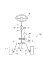
- FIG. 1 is a configuration diagram of an electric power steering device according to a first embodiment of the present invention.
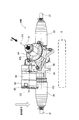
- FIG. 2 is a view of a state where the electric power steering apparatus according to the first embodiment of the present invention is assembled to a vehicle, as viewed from the side of the vehicle.
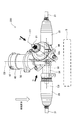
- FIG. 3 is a view of the electric power steering device according to the first embodiment of the present invention assembled to a vehicle as seen from above the vehicle.
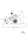
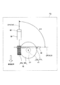
- FIG. 4 is a schematic diagram showing the relationship between the first axis and the second axis projected on the first plane.
- FIG. 5 is a schematic diagram showing the relationship between the second axis and the third axis projected on the second plane.
- FIG. 6 is a side view of the electric power steering device according to the second embodiment of the present invention, which is mounted on the vehicle as viewed from the side of the vehicle.
- FIG. 7 is a view of the electric power steering apparatus according to the second embodiment of the present invention assembled to a vehicle as seen from above the vehicle.
- FIG. 8 is a schematic diagram showing the relationship between the first axis and the second axis projected on the first plane.
- FIG. 9 is a schematic diagram showing the relationship between the second axis and the third axis projected on the second plane.
- the electric power steering device 100 is a device that is mounted on a vehicle and assists a steering force with respect to a steering device that converts steering torque applied to a steering wheel 10 by a driver to steer the wheels 1.
- FIG. 1 is a configuration diagram of an electric power steering device 100
- FIG. 2 is a view of an electric power steering device 100 assembled in a vehicle as seen from a side of the vehicle
- FIG. 3 is an electric power steering device 100. It is the figure which looked at from the upper part of the vehicle.
- the electric power steering apparatus 100 includes a steering shaft 20 connected to the steering wheel 10 and a rack shaft 30 that steers the wheels 1 as the steering shaft 20 rotates.
- the rack shaft 30 is connected to the wheel 1 via a tie rod 31 and a knuckle arm 32, and the wheel 1 is steered by the displacement of the rack shaft 30.
- the steering shaft 20 includes an input shaft 21 that rotates in response to a steering operation performed by a driver who operates the steering wheel 10, an output shaft 22 as a pinion shaft that displaces the rack shaft 30, and an input shaft 21 and an output shaft 22.
- the torsion bar 23 is connected to the torsion bar 23.
- the output shaft 22 and the rack shaft 30 are connected to each other via the first transmission portion 41.
- the first transmission portion 41 includes a pinion gear 41 a provided on the end of the output shaft 22 and a rack gear 41 b provided on the rack shaft 30.
- the pinion gear 41a and the rack gear 41b mesh with each other, and the torque of the output shaft 22 is converted into an axial load of the rack shaft 30 and transmitted to the rack shaft 30 via the pinion gear 41a and the rack gear 41b.
- the rack shaft 30 is displaced in the axial direction by the transmitted torque to steer the wheels 1.
- the electric power steering device 100 includes an electric motor 50 driven according to a steering operation, a torque sensor 51 for detecting a torque acting on the torsion bar 23, and an electric motor 50 for the electric motor 50 according to a detection value of the torque sensor 51.
- the controller 60 which controls drive is further provided.
- the output shaft of the electric motor 50 is connected to the output shaft 22 of the steering shaft 20 via the second transmission portion 42.
- the second transmission portion 42 includes a worm shaft 42 a provided on the output shaft of the electric motor 50 and a worm wheel 42 b provided on the output shaft 22.
- the worm shaft 42a and the worm wheel 42b mesh with each other, and the torque of the electric motor 50 is transmitted to the output shaft 22 via the worm shaft 42a and the worm wheel 42b.
- the torque transmitted from the electric motor 50 to the output shaft 22 is further transmitted to the rack shaft 30 via the pinion gear 41a and the rack gear 41b.
- the controller 60 includes a CPU (Central Processing Unit) that performs arithmetic processing, a ROM (Read-Only Memory) that stores a control program executed by the CPU, and a RAM (random access memory) that stores the arithmetic result of the CPU. And a microcomputer including.
- the controller 60 may be composed of a single microcomputer or may be composed of a plurality of microcomputers.
- the controller 60 is disposed adjacent to the electric motor 50, and is provided on the opposite side of the worm shaft 42a with the electric motor 50 interposed therebetween, as shown in FIGS. 2 and 3, for example.
- the controller 60 is provided with a heat sink 62 on the side opposite to the electric motor 50 for radiating internal heat.
- the heat sink 62 is formed in a concavo-convex shape with a metal material having excellent thermal conductivity, such as aluminum, in order to efficiently dissipate heat generated by the elements in the controller 60 to the outside.
- the torque sensor 51 detects the steering torque applied to the input shaft 21 according to the steering operation by the driver, and outputs a voltage signal corresponding to the detected steering torque to the controller 60.
- the controller 60 calculates the torque output by the electric motor 50 based on the voltage signal from the torque sensor 51, and controls the drive of the electric motor 50 so that the torque is generated.
- the electric power steering apparatus 100 detects the steering torque applied to the input shaft 21 by the torque sensor 51, and based on the detection result, controls the drive of the electric motor 50 by the controller 60 to drive the driver. Assist steering operation.
- the electric power steering device 100 further includes a rack housing 34 that accommodates the rack shaft 30, and a worm housing 44 that accommodates the worm wheel 42b.
- the electric power steering device 100 is attached to the vehicle frame 3 by fixing the rack housing 34 to a bracket (not shown) extending from the vehicle frame 3.
- the rack housing 34 further accommodates a pinion gear 41a provided on the output shaft 22.
- a boot 35 is attached to the rack housing 34 to cover the connecting portion between the rack shaft 30 and the tie rod 31.
- the worm housing 44 further accommodates the output shaft 22 provided with the worm wheel 42b and the worm shaft 42a that meshes with the worm wheel 42b.
- An electric motor 50 that drives the worm shaft 42a is attached to the worm housing 44.
- the worm housing 44 is arranged vertically above the rack housing 34 in a state where the electric power steering device 100 is assembled to the vehicle.
- the worm housing 44 can be used even when traveling on a river or the like having a certain depth of water like an all-terrain vehicle.
- the water can be prevented from entering the worm housing 44 and the water can enter the electric motor 50 assembled to the worm housing 44 as compared with the case where the water is arranged vertically below the rack housing 34. Can be prevented.
- the space for arranging the devices constituting the vehicle is limited. Therefore, for example, as shown in FIG. Is provided with a radiator 5 for cooling engine cooling water (not shown).
- the radiator 5 serving as a heat source is arranged in front of the electric power steering device 100, the electric power steering device 100 can be operated when the radiator fan (not shown) is rotating or the vehicle is traveling. It will be heated by the heat emitted from the radiator 5.
- the controller 60 of the electric power steering apparatus 100 executes a function limitation such as limiting the driving force of the electric motor 50 for circuit protection when the temperature rises. Therefore, if the controller 60 is heated by the heat released from the radiator 5, the operation of the electric motor 50 is limited, and as a result, it becomes difficult to stably operate the electric power steering device 100.
- the temperature of the controller 60 is prevented from rising due to the heat released from the radiator 5, At least a part of the controller 60 is arranged on the opposite side of the radiator 5 serving as a heat source with the rack housing 34 accommodating the rack shaft 30 interposed therebetween.
- the electric power steering device 100 is viewed in the horizontal direction from the radiator 5 side, at least a part of the controller 60 overlaps the rack housing 34 and is invisible.
- the rack housing 34 functions as a heat shield member that shields the hot air from the radiator 5 and the radiator fan from directly hitting the controller 60. It will be.
- the heat sink 62 is also arranged on the opposite side of the radiator 5 with the rack housing 34 sandwiched therebetween so that the heat released from the radiator 5 does not move to the inside of the controller 60 via the heat sink 62.
- the rack housing 34 functions as a heat shield member that shields the hot air from the radiator 5 and the radiator fan from directly hitting the heat sink 62.
- the rack housing 34 as a heat shield member, it is possible to prevent the controller 60 and the heat sink 62 from being heated by the heat emitted from the radiator 5. Therefore, even when a heat source such as the radiator 5 is arranged around the electric power steering device 100, the temperature of the controller 60 is suppressed from rising due to the radiant heat emitted from the heat source, and as a result, The electric power steering device 100 can always be stably operated.
- FIG. 4 shows the first axis C1 and the first axis C1 projected onto a first plane P1 parallel to the second axis C2 which is the axis center of the worm shaft 42a and includes the first axis C1 which is the axis center of the output shaft 22.
- FIG. 5 is a schematic view of the relationship with the two-axis center C2 viewed from the direction indicated by the arrow A in FIG. 2, and FIG. 5 is a second-axis center C2 projected on a second plane P2 orthogonal to the first-axis center C1.
- FIG. 4 is a schematic diagram showing the relationship between the third shaft center C3, which is the axial center of the rack shaft 30, as seen from the direction indicated by arrow B in FIG. 3.
- the controller 60 Since the controller 60 is arranged on the second axis C2 together with the electric motor 50, when the first angle ⁇ 1 is smaller than 90 degrees, the controller 60 approaches the pinion gear 41a arranged on the first axis C1. In this state, that is, the controller 60 approaches the rack housing 34. On the other hand, when the first angle ⁇ 1 is larger than 90 degrees, the controller 60 is separated from the rack housing 34. When the first angle ⁇ 1 is 90 degrees, the output shaft 22 and the worm shaft 42a are orthogonal to each other.
- the second projection axis CP2 obtained by projecting the second axis C2 of the worm shaft 42a onto the second plane P2 and the third axis C3 of the rack shaft 30 appearing on the second plane P2.
- a predetermined second angle ⁇ 2 is formed between the projected third projection axis CP3 and the projected third projection axis CP3.
- the controller 60 Since the controller 60 is arranged on the second axis C2, when the second angle ⁇ 2 is larger than 0 degrees, the controller 60 approaches the rack shaft 30, that is, the controller 60 approaches the rack housing 34. It becomes a state. On the other hand, when the second angle ⁇ 2 is smaller than 0 degree, the controller 60 is separated from the rack housing 34. When the second angle ⁇ 2 is 0 degree, the second projection axis CP2 and the third projection axis CP3 are parallel to each other.
- the controller 60 and the heat sink 62 should be hidden in the rack housing 34 as much as possible when viewed from the radiator 5 side. It is preferable to arrange the controller 60 and the heat sink 62.
- the second angle ⁇ 2 is set to 0° or slightly smaller than 0° and the first angle is set to 0°.
- ⁇ 1 may be set to be smaller than 90 degrees, and the controller 60 and the heat sink 62 may be arranged on the opposite side of the radiator 5 with the rack housing 34 interposed therebetween.
- the controller 60 is arranged vertically below the rack housing 34. Therefore, depending on the position of the radiator 5, hot air from the radiator 5 may directly hit the controller 60. There is. Therefore, the magnitude of the first angle ⁇ 1 is appropriately set according to the positional relationship between the radiator 5 and the rack housing 34.
- the magnitudes of the first angle ⁇ 1 and the second angle ⁇ 2, that is, the positional relationship between the output shaft 22, the worm shaft 42a, and the rack shaft 30 are set according to the positional relationship between the radiator 5 and the rack housing 34. By doing so, the hot air flowing from the radiator 5 toward the controller 60 and the heat sink 62 can be blocked by the rack housing 34. Therefore, it is possible to prevent the temperature of the controller 60 from rising.
- the rack housing 34 as a heat shielding member, it is not necessary to separately provide the electric power steering device 100 with a member that suppresses the hot air from the radiator 5 from hitting the controller 60 and the heat sink 62. Therefore, the temperature rise of the controller 60 can be suppressed without increasing the manufacturing cost of the electric power steering device 100.
- the first angle ⁇ 1 and the second angle ⁇ 2 are set so that the second axis C2 of the worm shaft 42a and the third axis C3 of the rack shaft 30 are substantially parallel to each other.
- the electric power steering device 100 can be made compact. Therefore, even when another device is arranged around the electric power steering device 100, it is possible to prevent the hot air from the radiator 5 from directly hitting the controller 60 and the heat sink 62.
- the controller 60 does not need to be strictly arranged on the second axis C2, and may be arranged so that the position with respect to the rack housing 34 is changed together with the electric motor 50 by changing the first angle ⁇ 1.
- the first angle ⁇ 1 is not limited to the angle at the position shown in FIG. 4, and is not limited to the angle formed by the first axis C1 and the first projection axis CP1 on the first plane P1. May be the angle of the position.
- the second angle ⁇ 2 is not limited to the angle at the position shown in FIG. 5 and may be any angle formed by the second projection axis CP2 and the third projection axis CP3 on the second plane P2. The angle of other positions may be used.
- the controller 60 is arranged on the opposite side of the radiator 5 serving as a heat source with the rack housing 34 accommodating the rack shaft 30 interposed therebetween.
- the rack housing 34 as a heat shield member, it is possible to prevent the controller 60 and the heat sink 62 from being heated by the heat emitted from the radiator 5. Therefore, even when a heat source such as the radiator 5 is arranged around the electric power steering device 100, the temperature of the controller 60 is suppressed from rising due to the radiant heat emitted from the heat source, and as a result, The electric power steering device 100 can always be stably operated.
- FIG. 6 is a view of the electric power steering device 200 assembled in the vehicle as seen from the side of the vehicle
- FIG. 7 is a view of the electric power steering device 200 as seen from above the vehicle.
- the basic configuration of the electric power steering device 200 is the same as that of the electric power steering device 100 according to the first embodiment.
- the electric power steering apparatus 200 is different from the electric power steering apparatus 100 in that the controller 60 is arranged on the opposite side of the radiator 5 with the electric motor 50 interposed in addition to the rack housing 34.
- the controller 60 is generated by the heat released from the radiator 5.
- the controller 60 is arranged on the opposite side of the radiator 5 serving as a heat source with the rack housing 34 accommodating the rack shaft 30 and the electric motor 50 interposed therebetween so that the temperature does not rise.
- the rack housing 34 between the radiator 5 and the controller 60, the hot air from the radiator 5 and the radiator fan directly hits the controller 60 in the rack housing 34, as in the first embodiment. It will function as a heat shielding member for shielding the above. Furthermore, by disposing the electric motor 50 between the radiator 5 and the controller 60, the controller 60 is arranged at a position farther from the radiator 5 than in the first embodiment. Therefore, the controller 60 is less likely to be heated by the heat emitted from the radiator 5.
- the heat sink 62 is also arranged on the opposite side of the radiator 5 with the rack housing 34 and the electric motor 50 sandwiched therebetween so that the heat released from the radiator 5 does not move to the inside of the controller 60 via the heat sink 62.
- the rack housing 34 functions as a heat shield member that shields the hot air from the radiator 5 and the radiator fan from directly hitting the heat sink 62.
- the heat sink 62 is arranged at a position distant from the radiator 5 as compared with the first embodiment. Therefore, the heat sink 62 is less likely to be heated by the heat emitted from the radiator 5.
- the rack housing 34 as a heat shield member and arranging the controller 60 and the heat sink 62 at positions away from the radiator 5, the controller 60 and the heat sink 62 are heated by the heat emitted from the radiator 5. It is possible to suppress that.
- the electric power steering device 200 can always be stably operated.
- FIG. 8 shows the first axis C1 projected onto a first plane P1 parallel to the second axis C2 which is the axis center of the worm shaft 42a and which includes the first axis C1 which is the axis center of the output shaft 22 and the first axis C1.
- FIG. 9 is a schematic view of the relationship with the two-axis center C2 viewed from the direction indicated by the arrow C in FIG. 7, and FIG.
- FIG. 9 is a second-axis center C2 projected on a second plane P2 orthogonal to the first-axis center C1.
- FIG. 9 is a schematic view of the relationship between the rack shaft 30 and a third axis C3, which is the axial center of the rack shaft 30, as seen from the direction indicated by arrow D in FIG. 7.
- a predetermined distance is provided between the first axis C1 of the output shaft 22 and the first projection axis CP1 on which the second axis C2 of the worm shaft 42a is projected on the first plane P1.
- the controller 60 Since the controller 60 is arranged on the second axis C2 together with the electric motor 50, when the first angle ⁇ 1 is smaller than 90 degrees, the controller 60 approaches the pinion gear 41a arranged on the first axis C1. In this state, that is, the controller 60 approaches the rack housing 34. On the other hand, when the first angle ⁇ 1 is larger than 90 degrees, the controller 60 is separated from the rack housing 34. When the first angle ⁇ 1 is 90 degrees, the output shaft 22 and the worm shaft 42a are orthogonal to each other.
- the second axis C2 of the worm shaft 42a is projected on the second plane P2, and the third axis C3 of the rack shaft 30 is on the second plane P2.
- a predetermined second angle ⁇ 2 is formed between the projected third projection axis CP3 and the projected third projection axis CP3.
- the controller 60 Since the controller 60 is arranged on the second axis C2, when the second angle ⁇ 2 is set to 90 degrees, the electric motor 50 is located between the controller 60 and the rack shaft 30, so that the controller 60 can move the rack shaft 30. From the rack housing 34, that is, the controller 60 is farthest from the rack housing 34.
- the controller 60 comes close to the rack housing 34.
- the second angle ⁇ 2 is 0 degree
- the second projection axis CP2 and the third projection axis CP3 are parallel to each other.
- the controller 60 and the heat sink 62 are hidden by the rack housing 34 as much as possible when viewed from the radiator 5 side. It is preferable to dispose the heat sink 62 and separate the controller 60 and the heat sink 62 from the radiator 5.
- the second angle ⁇ 2 is set to 90 degrees or 90 degrees.
- the first angle ⁇ 1 may be set to around 90 degrees, and the controller 60 and the heat sink 62 may be arranged on the opposite side of the radiator 5 with the rack housing 34 and the electric motor 50 interposed therebetween.
- the controller 60 is arranged vertically below the rack housing 34. Therefore, depending on the position of the radiator 5, hot air from the radiator 5 may directly hit the controller 60. There is. Therefore, the magnitude of the first angle ⁇ 1 is appropriately set according to the positional relationship between the radiator 5 and the rack housing 34.
- the magnitudes of the first angle ⁇ 1 and the second angle ⁇ 2, that is, the positional relationship between the output shaft 22, the worm shaft 42a, and the rack shaft 30 are set according to the positional relationship between the radiator 5 and the rack housing 34. By doing so, the hot air flowing from the radiator 5 toward the controller 60 and the heat sink 62 can be blocked by the rack housing 34. Therefore, it is possible to prevent the temperature of the controller 60 from rising.
- the rack housing 34 and the electric motor 50 are arranged between the radiator 60 and the controller 60 and the heat sink 62, and the controller 60 and the heat sink 62 are located relatively far from the radiator 5.
- first angle ⁇ 1 is not limited to the angle at the position shown in FIG. 8 and may be any other angle as long as it is an angle formed by the first axis C1 and the first projection axis CP1 on the first plane P1. May be the angle of the position.
- second angle ⁇ 2 is not limited to the angle at the position shown in FIG. 9 and may be any angle formed by the second projection axis CP2 and the third projection axis CP3 on the second plane P2. The angle of other positions may be used.
- the controller 60 is arranged on the side opposite to the radiator 5 serving as a heat source with the electric motor 50 sandwiched between the rack housing 34 accommodating the rack shaft 30.
- the rack housing 34 as a heat shield member and arranging the controller 60 at a position relatively distant from the radiator 5, the controller 60 and the heat sink 62 are heated by the heat emitted from the radiator 5. It is possible to suppress that. Therefore, even when a heat source such as the radiator 5 is arranged around the electric power steering device 200, the temperature of the controller 60 is suppressed from rising due to the radiant heat emitted from the heat source, and as a result, The electric power steering device 200 can always be stably operated.
- the worm housing 44 is arranged vertically above the rack housing 34.
- the worm housing 44 may be arranged vertically below the rack housing 34. This makes it possible to effectively use the space vertically below the rack housing 34.
- the controller 60 and the heat sink 62 are arranged on the opposite side of the radiator 5 with the rack housing 34 interposed therebetween by appropriately setting the sizes of the first angle ⁇ 1 and the second angle ⁇ 2. It is possible.
- the controller 60 is provided on the opposite side of the worm shaft 42a with the electric motor 50 interposed therebetween.
- the controller 60 may be arranged between the electric motor 50 and the worm shaft 42a as long as the controller 60 is arranged around the electric motor 50, or the controller 60 is attached to the outer peripheral surface of the electric motor 50. Good.
- the heat sink 62 is provided on the opposite side of the electric motor 50 with the controller 60 sandwiched therebetween.
- the heat sink 62 may be provided to the controller 60 in any manner as long as it can release the heat generated by the elements in the controller 60 to the outside. And may be formed so as to project radially outward.
- the heat source is the radiator 5
- the heat source is not limited to the radiator 5 and may be an engine body or an exhaust pipe through which exhaust gas discharged from the engine flows. ..
- the heat source is arranged in front of the electric power steering devices 100 and 200
- the heat source is arranged behind, above, and below the electric power steering devices 100 and 200. May be.
- the worm housing 44 is arranged vertically below the rack housing 34 and the controller 60 and the electric motor 50 are separated from the heat source.
- the steering wheel is the steering wheel 10.
- the steering handle may be of other forms such as a bar handle or a control stick.
- At least a part of the controller 60 is arranged on the opposite side of the radiator 5 with the rack housing 34 accommodating the rack shaft 30 interposed therebetween.
- the controller 60 is arranged on the opposite side of the radiator 5 serving as a heat source with the rack housing 34 accommodating the rack shaft 30 interposed therebetween.
- the rack housing 34 as a heat shield member, it is possible to prevent the controller 60 and the heat sink 62 from being heated by the heat emitted from the radiator 5. Therefore, even when a heat source such as the radiator 5 is arranged around the electric power steering devices 100 and 200, the temperature of the controller 60 is suppressed from rising due to the radiant heat emitted from the heat source, resulting in As a result, the electric power steering devices 100 and 200 can always be stably operated.
- the rack housing 34 is used as a heat shielding member, it is not necessary to separately provide the electric power steering devices 100 and 200 with a member that prevents hot air from the radiator 5 from hitting the controller 60 and the heat sink 62. .. Therefore, the temperature rise of the controller 60 can be suppressed without increasing the manufacturing cost of the electric power steering devices 100, 200.
- the controller 60 has a heat sink 62 that radiates the heat of the controller 60, and the controller 60 is arranged such that at least a part of the heat sink 62 is located on the opposite side of the radiator 5 with the rack housing 34 interposed therebetween. ..
- the controller 60 is arranged such that at least a part of the heat sink 62 is located on the opposite side of the radiator 5 with the rack housing 34 interposed therebetween. Therefore, the heat released from the radiator 5 is suppressed from moving to the inside of the controller 60 via the heat sink 62 and raising the temperature of the controller 60. Therefore, even when a heat source such as the radiator 5 is arranged around the electric power steering devices 100 and 200, the temperature of the controller 60 is suppressed from rising due to the radiant heat emitted from the heat source, resulting in As a result, the electric power steering devices 100 and 200 can always be stably operated.
- controller 60 is arranged on the side opposite to the radiator 5 with the electric motor 50 interposed therebetween in addition to the rack housing 34.
- the controller 60 is arranged on the opposite side of the radiator 5 with the electric motor 50 sandwiched in addition to the rack housing 34.
- the rack housing 34 is used as a heat shield member and the controller 60 is relatively separated from the radiator 5. It becomes possible to arrange it in a position. Therefore, even when a heat source such as the radiator 5 is arranged around the electric power steering device 200, the temperature of the controller 60 is suppressed from rising due to the radiant heat emitted from the heat source, and as a result, The electric power steering device 200 can always be stably operated.
- the controller 60 is arranged adjacent to the electric motor 50, and includes the second axial center C2 that is the axial center of the worm shaft 42a and the second axial center C2 that includes the first axial center C1 that is the axial center of the output shaft 22.
- An angle formed by the first projection axis CP1 projected on the first plane P1 parallel to the first axis P1 and the first axis C1 is defined as a first angle ⁇ 1
- the second axis C2 is orthogonal to the first axis C1.
- the angle formed by the second projection axis CP2 projected on the second plane P2 and the third projection axis CP3 projecting the third axis C3 that is the axial center of the rack shaft 30 on the second plane P2 is the second angle.
- the position of the controller 60 with respect to the rack housing 34 can be appropriately changed by changing the sizes of the first angle ⁇ 1 and the second angle ⁇ 2. Therefore, regardless of the positional relationship between the radiator 5 and the rack housing 34, at least a part of the controller 60 can be moved to the rack by changing the sizes of the first angle ⁇ 1 and the second angle ⁇ 2. It is possible to dispose it on the side opposite to the radiator 5 with the housing 34 interposed therebetween. Therefore, no matter where the heat source such as the radiator 5 is arranged with respect to the electric power steering devices 100 and 200, the temperature of the controller 60 is prevented from rising due to the radiant heat emitted from the heat source. Therefore, as a result, the electric power steering devices 100 and 200 can always be stably operated.
Landscapes
- Engineering & Computer Science (AREA)
- Mechanical Engineering (AREA)
- Chemical & Material Sciences (AREA)
- Combustion & Propulsion (AREA)
- Transportation (AREA)
- Power Steering Mechanism (AREA)
Abstract
車両に設けられる熱源の周辺に配置される電動パワーステアリング装置(100)は、車輪(1)を転舵するラックシャフト(30)と、ラックシャフト(30)のラックギヤ(41b)と噛み合うピニオンギヤ(41a)が設けられる出力シャフト(22)と、出力シャフト(22)に設けられるウォームホイール(42b)と、ウォームホイール(42b)と噛み合うウォームシャフト(42a)と、ウォームシャフト(42a)を回転駆動する電動モータ(50)と、電動モータ(50)の駆動を制御するコントローラ(60)と、を備え、コントローラ(60)の少なくとも一部は、ラックシャフト(30)が収容されるラックハウジング(34)を挟んで熱源とは反対側に配置される。
Description
本発明は、電動パワーステアリング装置に関するものである。
JP2006-232059Aには、比較的車幅が狭い全地形対応車(ATV : All Terrain Vehicle)に組み付けられた電動パワーステアリング装置が開示されている。
JP2006-232059Aに記載される電動パワーステアリング装置は、車両の前後方向において、ラジエータの後方に配置されている。このため、電動パワーステアリング装置は、ラジエータから放出された熱により加熱されることとなる。電動パワーステアリング装置は、モータを駆動するコントローラを有するため、ラジエータから放出された熱によってコントローラが加熱されると、モータの出力が制限され、結果として、電動パワーステアリング装置の作動が不安定になるおそれがある。
本発明は、電動パワーステアリング装置を安定して作動させることを目的とする。
本発明のある態様によれば、車両に設けられる熱源の周辺に配置される電動パワーステアリング装置は、車輪を転舵するラックシャフトと、前記ラックシャフトのラックギヤと噛み合うピニオンギヤが設けられるピニオンシャフトと、前記ピニオンシャフトに設けられるウォームホイールと、前記ウォームホイールと噛み合うウォームシャフトと、前記ウォームシャフトを回転駆動する電動モータと、前記電動モータの駆動を制御する制御部と、を備え、前記制御部の少なくとも一部は、前記ラックシャフトが収容されるラックハウジングを挟んで前記熱源とは反対側に配置される。
以下、図面を参照して、本発明の実施形態について説明する。
<第1実施形態>
図1から図3を参照して、本発明の第1実施形態に係る電動パワーステアリング装置100について説明する。電動パワーステアリング装置100は、車両に搭載され、運転者がステアリングホイール10に加える操舵トルクを変換して車輪1を転舵するステアリング装置に対して、操舵力を補助する装置である。
図1から図3を参照して、本発明の第1実施形態に係る電動パワーステアリング装置100について説明する。電動パワーステアリング装置100は、車両に搭載され、運転者がステアリングホイール10に加える操舵トルクを変換して車輪1を転舵するステアリング装置に対して、操舵力を補助する装置である。
以下では、電動パワーステアリング装置100が組み付けられる車両が、比較的車幅が狭い全地形対応車(ATV : All Terrain Vehicle)や多用途四輪車(SSV : Side by Side Vehicle)である場合について説明する。図1は、電動パワーステアリング装置100の構成図であり、図2は、車両に組み付けられた電動パワーステアリング装置100を車両の側方から見た図であり、図3は、電動パワーステアリング装置100を車両の上方から見た図である。
図1に示すように、電動パワーステアリング装置100は、ステアリングホイール10に連結されるステアリングシャフト20と、ステアリングシャフト20の回転に伴って車輪1を転舵するラックシャフト30と、を備える。ラックシャフト30は、タイロッド31及びナックルアーム32を介して車輪1に連結されており、車輪1は、ラックシャフト30の変位によって転舵される。
ステアリングシャフト20は、運転者がステアリングホイール10を操作するステアリング操作に伴って回転する入力シャフト21と、ラックシャフト30を変位させるピニオンシャフトとしての出力シャフト22と、入力シャフト21と出力シャフト22とを連結するトーションバー23と、により構成される。
出力シャフト22とラックシャフト30とは、第1伝達部41を介して互いに連結されている。第1伝達部41は、出力シャフト22の端部に設けられるピニオンギヤ41aと、ラックシャフト30に設けられるラックギヤ41bと、からなる。ピニオンギヤ41aとラックギヤ41bとは互いに噛み合っており、出力シャフト22のトルクは、ピニオンギヤ41a及びラックギヤ41bを介してラックシャフト30の軸方向の荷重に変換されてラックシャフト30に伝達される。これにより、ラックシャフト30は、伝達されるトルクによりその軸方向に変位し、車輪1を転舵する。
また、電動パワーステアリング装置100は、ステアリング操作に応じて駆動される電動モータ50と、トーションバー23に作用するトルクを検出するトルクセンサ51と、トルクセンサ51の検出値に応じて電動モータ50の駆動を制御するコントローラ60と、を更に備える。電動モータ50の出力軸は、第2伝達部42を介してステアリングシャフト20の出力シャフト22に連結されている。
第2伝達部42は、電動モータ50の出力軸に設けられるウォームシャフト42aと、出力シャフト22に設けられるウォームホイール42bと、からなる。ウォームシャフト42aとウォームホイール42bとは互いに噛み合っており、電動モータ50のトルクは、ウォームシャフト42a及びウォームホイール42bを介して出力シャフト22に伝達される。電動モータ50から出力シャフト22に伝達されたトルクは、ピニオンギヤ41a及びラックギヤ41bを介してラックシャフト30に更に伝達される。
コントローラ60は、演算処理を行うCPU(Central Processing Unit)と、CPUにより実行される制御プログラム等を記憶するROM(Read-Only Memory)と、CPUの演算結果等を記憶するRAM(random access memory)と、を含むマイクロコンピュータで構成される。コントローラ60は、単一のマイクロコンピュータで構成されていてもよいし、複数のマイクロコンピュータで構成されていてもよい。コントローラ60は、電動モータ50に隣接して配置されており、例えば、図2及び図3に示すように、電動モータ50を挟んでウォームシャフト42aとは反対側に設けられる。
また、図2及び図3に示すように、コントローラ60には、内部の熱を放出するためにヒートシンク62が、電動モータ50とは反対側に設けられる。ヒートシンク62は、コントローラ60内の素子で発生した熱を外部へと効率的に放出するため、アルミニウム等の熱伝導性に優れた金属材料によって凹凸状に形成される。このようにコントローラ60にヒートシンク62を設けることで、コントローラ60の温度上昇が抑制されるため、電動モータ50を安定して駆動させることが可能となる。
トルクセンサ51は、運転者によるステアリング操作に伴って入力シャフト21に付与される操舵トルクを検出し、検出した操舵トルクに対応する電圧信号をコントローラ60に出力する。コントローラ60は、トルクセンサ51からの電圧信号に基づいて、電動モータ50が出力するトルクを演算し、そのトルクが発生するように電動モータ50の駆動を制御する。
このように、電動パワーステアリング装置100は、入力シャフト21に付与される操舵トルクをトルクセンサ51にて検出し、その検出結果に基づいて電動モータ50の駆動をコントローラ60にて制御して運転者のステアリング操作をアシストする。
また、電動パワーステアリング装置100は、図2及び図3に示すように、ラックシャフト30を収容するラックハウジング34と、ウォームホイール42bを収容するウォームハウジング44と、をさらに備える。電動パワーステアリング装置100は、車両フレーム3から延びる図示しないブラケットにラックハウジング34が固定されることによって車両フレーム3に取り付けられる。
ラックハウジング34内には、出力シャフト22に設けられるピニオンギヤ41aがさらに収容される。また、ラックハウジング34には、ラックシャフト30とタイロッド31との連結部を覆うブーツ35が組み付けられる。
ウォームハウジング44内には、ウォームホイール42bが設けられる出力シャフト22と、ウォームホイール42bと噛み合うウォームシャフト42aと、がさらに収容される。また、ウォームハウジング44には、ウォームシャフト42aを駆動する電動モータ50が組み付けられる。
また、ウォームハウジング44は、図2及び図3に示すように、電動パワーステアリング装置100が車両に組み付けられた状態において、ラックハウジング34の鉛直方向上方に配置される。このように、ウォームハウジング44がラックハウジング34の鉛直方向上方に配置されるため、全地形対応車のように、ある程度の水深がある河川等を走行するような場合であっても、ウォームハウジング44がラックハウジング34の鉛直方向下方に配置される場合と比較し、ウォームハウジング44内に水が侵入することを防止することができるとともに、ウォームハウジング44に組み付けられる電動モータ50に水が侵入することを防止することができる。
ここで、全地形対応車のように比較的車幅が狭い車両では、車両を構成する装置を配置するスペースが限られるため、例えば、図2に示すように、電動パワーステアリング装置100の近傍には、図示しないエンジンの冷却水を冷却するためのラジエータ5が配置される。このように、電動パワーステアリング装置100の前方に熱源となるラジエータ5が配置されていると、図示しないラジエータファンが回転しているときや車両が走行しているとき、電動パワーステアリング装置100は、ラジエータ5から放出された熱により加熱されることとなる。
特に、電動パワーステアリング装置100のコントローラ60は、温度が上昇すると回路保護のために電動モータ50の駆動力を制限するといった機能制限を実行する。このため、コントローラ60がラジエータ5から放出された熱により加熱されてしまうと、電動モータ50の作動が制限され、結果として、電動パワーステアリング装置100を安定して作動させることが困難となる。
そこで、第1実施形態では、電動パワーステアリング装置100の周辺にラジエータ5のような熱源が配置された場合であっても、ラジエータ5から放出される熱によってコントローラ60の温度が上昇しないように、コントローラ60の少なくとも一部を、ラックシャフト30を収容するラックハウジング34を挟んで熱源となるラジエータ5とは反対側に配置している。換言すれば、ラジエータ5側から電動パワーステアリング装置100を水平方向に見た場合、コントローラ60の少なくとも一部は、ラックハウジング34と重なり合って見えない状態となっている。
このように、ラジエータ5とコントローラ60との間にラックハウジング34を配置することで、ラックハウジング34は、ラジエータ5及びラジエータファンからの熱風がコントローラ60へ直接当たることを遮る熱遮蔽部材として機能することになる。
また、ラジエータ5から放出された熱がヒートシンク62を介してコントローラ60の内部へ移動しないように、ヒートシンク62もラックハウジング34を挟んでラジエータ5とは反対側に配置されている。
この場合もラックハウジング34は、ラジエータ5及びラジエータファンからの熱風がヒートシンク62へ直接当たることを遮る熱遮蔽部材として機能することになる。
このように、ラックハウジング34を熱遮蔽部材として用いることによって、ラジエータ5から放出された熱によってコントローラ60やヒートシンク62が加熱されることを抑制することが可能である。したがって、電動パワーステアリング装置100の周辺にラジエータ5のような熱源が配置される場合であっても、熱源から放出される輻射熱によってコントローラ60の温度が上昇することが抑制されるため、結果として、電動パワーステアリング装置100を常に安定して作動させることができる。
次に、図2から図5を参照して、コントローラ60やヒートシンク62を、ラックハウジング34を挟んでラジエータ5とは反対側に配置可能とするための構成について説明する。図4は、出力シャフト22の軸中心である第1軸心C1を含みウォームシャフト42aの軸中心である第2軸心C2に平行な第1平面P1に投影された第1軸心C1と第2軸心C2との関係を図2の矢印Aで示される方向から見た模式図であり、図5は、第1軸心C1に直交する第2平面P2に投影された第2軸心C2とラックシャフト30の軸中心である第3軸心C3との関係を図3の矢印Bで示される方向から見た模式図である。
図4に示すように、出力シャフト22の第1軸心C1と、ウォームシャフト42aの第2軸心C2が第1平面P1に投影された第1投影軸心CP1と、の間には、所定の第1角度α1が形成される。
第2軸心C2上には電動モータ50とともにコントローラ60が配置されるため、第1角度α1を90度よりも小さくすると、コントローラ60は第1軸心C1上に配置されるピニオンギヤ41aに近づいた状態、すなわち、コントローラ60がラックハウジング34に近づいた状態となる。一方、第1角度α1を90度よりも大きくすると、コントローラ60はラックハウジング34から離れた状態となる。なお、第1角度α1を90度とすると、出力シャフト22とウォームシャフト42aとは直交した状態となる。
また、図5に示すように、ウォームシャフト42aの第2軸心C2が第2平面P2に投影された第2投影軸心CP2と、ラックシャフト30の第3軸心C3が第2平面P2に投影された第3投影軸心CP3と、の間には、所定の第2角度α2が形成される。
第2軸心C2上にはコントローラ60が配置されるため、第2角度α2を0度よりも大きくすると、コントローラ60はラックシャフト30に近づいた状態、すなわち、コントローラ60がラックハウジング34に近づいた状態となる。一方、第2角度α2を0度よりも小さくすると、コントローラ60はラックハウジング34から離れた状態となる。なお、第2角度α2を0度にすると、第2投影軸心CP2と第3投影軸心CP3とは、平行になる。
ここで、ラジエータ5及びラジエータファンからの熱風がコントローラ60やヒートシンク62に直接当たらないようにするには、ラジエータ5側から見て、コントローラ60及びヒートシンク62が可能な限りラックハウジング34に隠れるようにコントローラ60及びヒートシンク62を配置することが好ましい。
このようにラジエータ5側から見て、ラックハウジング34に隠れるようにコントローラ60及びヒートシンク62を配置するには、第2角度α2を0度または0度よりもわずかに小さく設定するとともに、第1角度α1を90度よりも小さく設定し、コントローラ60やヒートシンク62を、ラックハウジング34を挟んでラジエータ5とは反対側に配置すればよい。
なお、第1角度α1を小さくし過ぎるとラックハウジング34よりも鉛直方向下方にコントローラ60が配置されてしまうため、ラジエータ5の位置によっては、ラジエータ5からの熱風がコントローラ60に直接当たってしまうおそれがある。このため、第1角度α1の大きさは、ラジエータ5とラックハウジング34との位置関係に応じて適宜設定される。
このように、第1角度α1及び第2角度α2の大きさ、すなわち、出力シャフト22とウォームシャフト42aとラックシャフト30との位置関係を、ラジエータ5とラックハウジング34との位置関係に応じて設定することで、ラジエータ5からコントローラ60やヒートシンク62に向かう熱風をラックハウジング34によって遮ることが可能である。このため、コントローラ60の温度が上昇してしまうことを抑制することができる。
また、ラックハウジング34を熱遮蔽部材として利用することによって、ラジエータ5からの熱風がコントローラ60やヒートシンク62に当たることを抑制する部材を電動パワーステアリング装置100に別途設ける必要がない。このため、電動パワーステアリング装置100の製造コストを増加させなくともコントローラ60の温度上昇を抑制することが可能である。
また、図2及び図3に示すように、ウォームシャフト42aの第2軸心C2とラックシャフト30の第3軸心C3とが略平行となるように、第1角度α1及び第2角度α2の大きさを設定することで、電動パワーステアリング装置100をコンパクト化することが可能である。このため、電動パワーステアリング装置100の周辺に他の装置が配置されている場合であっても、ラジエータ5からの熱風がコントローラ60やヒートシンク62に直接当たらないようにすることができる。
なお、コントローラ60は、厳密に第2軸心C2上に配置されている必要はなく、第1角度α1が変更されることで電動モータ50とともにラックハウジング34に対する位置が変わるように配置されていればよい。また、第1角度α1は、図4に示される位置の角度に限定されず、第1平面P1上において第1軸心C1と第1投影軸心CP1とにより形成される角度であれば、他の位置の角度であってもよい。同様に、第2角度α2は、図5に示される位置の角度に限定されず、第2平面P2上において第2投影軸心CP2と第3投影軸心CP3とにより形成される角度であれば、他の位置の角度であってもよい。
以上の第1実施形態によれば以下の効果を奏する。
電動パワーステアリング装置100では、コントローラ60の少なくとも一部が、ラックシャフト30を収容するラックハウジング34を挟んで熱源となるラジエータ5とは反対側に配置される。このように、ラックハウジング34を熱遮蔽部材として利用することによって、ラジエータ5から放出された熱によってコントローラ60やヒートシンク62が加熱されることを抑制することが可能である。したがって、電動パワーステアリング装置100の周辺にラジエータ5のような熱源が配置される場合であっても、熱源から放出される輻射熱によってコントローラ60の温度が上昇することが抑制されるため、結果として、電動パワーステアリング装置100を常に安定して作動させることができる。
<第2実施形態>
次に、図6から図9を参照して、本発明の第2実施形態に係る電動パワーステアリング装置200について説明する。以下では、第1実施形態と異なる点を中心に説明し、第1実施形態と同様の構成には、同一の符号を付し説明を省略する。図6は、車両に組み付けられた電動パワーステアリング装置200を車両の側方から見た図であり、図7は、電動パワーステアリング装置200を車両の上方から見た図である。
次に、図6から図9を参照して、本発明の第2実施形態に係る電動パワーステアリング装置200について説明する。以下では、第1実施形態と異なる点を中心に説明し、第1実施形態と同様の構成には、同一の符号を付し説明を省略する。図6は、車両に組み付けられた電動パワーステアリング装置200を車両の側方から見た図であり、図7は、電動パワーステアリング装置200を車両の上方から見た図である。
電動パワーステアリング装置200の基本的な構成は、第1実施形態に係る電動パワーステアリング装置100と同様である。電動パワーステアリング装置200では、コントローラ60が、ラックハウジング34に加えて電動モータ50を挟んでラジエータ5とは反対側に配置される点で電動パワーステアリング装置100と相違する。
第2実施形態では、図6及び図7に示すように、電動パワーステアリング装置200の周辺にラジエータ5のような熱源が配置された場合であっても、ラジエータ5から放出される熱によってコントローラ60の温度が上昇しないように、コントローラ60を、ラックシャフト30を収容するラックハウジング34及び電動モータ50を挟んで熱源となるラジエータ5とは反対側に配置している。
このように、ラジエータ5とコントローラ60との間にラックハウジング34を配置することで、ラックハウジング34は、上記第1実施形態と同様に、ラジエータ5及びラジエータファンからの熱風がコントローラ60へ直接当たることを遮る熱遮蔽部材として機能することになる。さらに、ラジエータ5とコントローラ60との間に電動モータ50を配置することで、コントローラ60は、上記第1実施形態と比べて、ラジエータ5から離れた位置に配置されることになる。このため、コントローラ60は、ラジエータ5から放出される熱によって加熱されにくくなる。
また、ラジエータ5から放出された熱がヒートシンク62を介してコントローラ60の内部へ移動しないように、ヒートシンク62もラックハウジング34及び電動モータ50を挟んでラジエータ5とは反対側に配置される。
この場合もラックハウジング34は、ラジエータ5及びラジエータファンからの熱風がヒートシンク62へ直接当たることを遮る熱遮蔽部材として機能することになる。さらに、ヒートシンク62は、上記第1実施形態と比べて、ラジエータ5から離れた位置に配置されることになる。このため、ヒートシンク62は、ラジエータ5から放出される熱によって加熱されにくくなる。
このように、ラックハウジング34を熱遮蔽部材として利用するとともに、コントローラ60及びヒートシンク62をラジエータ5から離れた位置に配置することによって、ラジエータ5から放出された熱によってコントローラ60やヒートシンク62が加熱されることを抑制することが可能である。
したがって、電動パワーステアリング装置200の周辺にラジエータ5のような熱源が配置される場合であっても、熱源から放出される輻射熱によってコントローラ60の温度が上昇することが抑制されるため、結果として、電動パワーステアリング装置200を常に安定して作動させることができる。
次に、図6から図9を参照して、コントローラ60やヒートシンク62を、ラックハウジング34及び電動モータ50を挟んでラジエータ5とは反対側に配置可能とするための構成について説明する。図8は、出力シャフト22の軸中心である第1軸心C1を含みウォームシャフト42aの軸中心である第2軸心C2に平行な第1平面P1に投影された第1軸心C1と第2軸心C2との関係を図7の矢印Cで示される方向から見た模式図であり、図9は、第1軸心C1に直交する第2平面P2に投影された第2軸心C2とラックシャフト30の軸中心である第3軸心C3との関係を図7の矢印Dで示される方向から見た模式図である。
図8に示すように、出力シャフト22の第1軸心C1と、ウォームシャフト42aの第2軸心C2が第1平面P1に投影された第1投影軸心CP1と、の間には、所定の第1角度α1が形成される。
第2軸心C2上には電動モータ50とともにコントローラ60が配置されるため、第1角度α1を90度よりも小さくすると、コントローラ60は第1軸心C1上に配置されるピニオンギヤ41aに近づいた状態、すなわち、コントローラ60がラックハウジング34に近づいた状態となる。一方、第1角度α1を90度よりも大きくすると、コントローラ60はラックハウジング34から離れた状態となる。なお、第1角度α1を90度とすると、出力シャフト22とウォームシャフト42aとは直交した状態となる。
また、図9に示すように、ウォームシャフト42aの第2軸心C2が第2平面P2に投影された第2投影軸心CP2と、ラックシャフト30の第3軸心C3が第2平面P2に投影された第3投影軸心CP3と、の間には、所定の第2角度α2が形成される。
第2軸心C2上にはコントローラ60が配置されるため、第2角度α2を90度にすると、コントローラ60とラックシャフト30との間に電動モータ50が位置することでコントローラ60はラックシャフト30から最も離れた状態、すなわち、コントローラ60がラックハウジング34から最も離れた状態となる。
一方、第2角度α2を90度よりも小さくまたは90度よりも大きくすると、コントローラ60はラックハウジング34に近づいた状態となる。なお、第2角度α2を0度にすると、第2投影軸心CP2と第3投影軸心CP3とは、平行になる。
ここで、ラジエータ5からの熱風がコントローラ60やヒートシンク62に直接当たらないようにするには、ラジエータ5側から見て、コントローラ60及びヒートシンク62が可能な限りラックハウジング34に隠れるようにコントローラ60及びヒートシンク62を配置するとともに、コントローラ60及びヒートシンク62をラジエータ5から離すことが好ましい。
このようにラジエータ5側から見て、ラックハウジング34に隠れるようにコントローラ60及びヒートシンク62を配置しつつ、コントローラ60及びヒートシンク62をラジエータ5から離すには、第2角度α2を90度または90度近傍に設定するとともに、第1角度α1を90度前後に設定し、コントローラ60やヒートシンク62を、ラックハウジング34及び電動モータ50を挟んでラジエータ5とは反対側に配置すればよい。
なお、第1角度α1を小さくし過ぎるとラックハウジング34よりも鉛直方向下方にコントローラ60が配置されてしまうため、ラジエータ5の位置によっては、ラジエータ5からの熱風がコントローラ60に直接当たってしまうおそれがある。このため、第1角度α1の大きさは、ラジエータ5とラックハウジング34との位置関係に応じて適宜設定される。
このように、第1角度α1及び第2角度α2の大きさ、すなわち、出力シャフト22とウォームシャフト42aとラックシャフト30との位置関係を、ラジエータ5とラックハウジング34との位置関係に応じて設定することで、ラジエータ5からコントローラ60やヒートシンク62に向かう熱風をラックハウジング34によって遮ることが可能である。このため、コントローラ60の温度が上昇してしまうことを抑制することができる。
特に、図6及び図7に示すように、コントローラ60及びヒートシンク62とラジエータ5との間にラックハウジング34及び電動モータ50が配置され、コントローラ60及びヒートシンク62がラジエータ5から比較的離れた位置に配置されるように、第1角度α1及び第2角度α2の大きさを設定することで、ラジエータ5から放出される熱がコントローラ60やヒートシンク62に影響を及ぼさないようにすることができる。
なお、第1角度α1は、図8に示される位置の角度に限定されず、第1平面P1上において第1軸心C1と第1投影軸心CP1とにより形成される角度であれば、他の位置の角度であってもよい。同様に、第2角度α2は、図9に示される位置の角度に限定されず、第2平面P2上において第2投影軸心CP2と第3投影軸心CP3とにより形成される角度であれば、他の位置の角度であってもよい。
以上の第2実施形態によれば以下の効果を奏する。
電動パワーステアリング装置200では、コントローラ60が、ラックシャフト30を収容するラックハウジング34に加えて電動モータ50を挟んで熱源となるラジエータ5とは反対側に配置される。このように、ラックハウジング34を熱遮蔽部材として利用するとともに、コントローラ60をラジエータ5から比較的離れた位置に配置することによって、ラジエータ5から放出された熱によってコントローラ60やヒートシンク62が加熱されることを抑制することが可能である。したがって、電動パワーステアリング装置200の周辺にラジエータ5のような熱源が配置される場合であっても、熱源から放出される輻射熱によってコントローラ60の温度が上昇することが抑制されるため、結果として、電動パワーステアリング装置200を常に安定して作動させることができる。
次に、上記各実施形態の変形例について説明する。以下に示すような変形例も本発明の範囲内であり、変形例に示される構成と上述の実施形態で説明した構成を組み合わせたり、以下の異なる変形例で説明する構成同士を組み合わせたりすることも可能である。
上記各実施形態では、ウォームハウジング44は、ラックハウジング34の鉛直方向上方に配置される。これに代えて、ウォームハウジング44は、ラックハウジング34の鉛直方向下方に配置されてもよい。これにより、ラックハウジング34の鉛直方向下方のスペースを有効利用することができる。なお、この場合であっても、第1角度α1及び第2角度α2の大きさを適宜設定することで、コントローラ60やヒートシンク62を、ラックハウジング34を挟んでラジエータ5とは反対側に配置することが可能である。
また、上記各実施形態では、コントローラ60が電動モータ50を挟んでウォームシャフト42aとは反対側に設けられる。これに代えて、コントローラ60は、電動モータ50の周辺に配置されていれば、電動モータ50とウォームシャフト42aとの間に配置されてもよいし、電動モータ50の外周面に組み付けられていてもよい。
また、上記各実施形態では、ヒートシンク62は、コントローラ60を挟んで電動モータ50とは反対側に設けられる。これに代えて、ヒートシンク62は、コントローラ60内の素子で発生した熱を外部へと放出可能であれば、コントローラ60に対してどのように設けられていてもよく、例えば、コントローラ60の外周面に設けられ、径方向外側に突出するように形成されてもよい。
また、上記各実施形態では、熱源がラジエータ5である場合について説明したが、熱源としては、ラジエータ5に限定されず、エンジン本体やエンジンから排出される排気ガスが流れる排気管であってもよい。また、上記各実施形態では、熱源が電動パワーステアリング装置100,200の前方に配置されている場合について説明したが、熱源は、電動パワーステアリング装置100,200の後方や上方、下方に配置されていてもよい。熱源が電動パワーステアリング装置100,200の上方に配置されている場合は、ウォームハウジング44をラックハウジング34の鉛直方向下方に配置し、コントローラ60及び電動モータ50を熱源から遠ざけることが好ましい。
また、上記各実施形態では、操舵ハンドルは、ステアリングホイール10である。これに代えて、操舵ハンドルは、例えば、バーハンドルや操縦桿等その他の形態のものであってもよい。
以下、本発明の実施形態の構成、作用、及び効果をまとめて説明する。
車両に設けられるラジエータ5の周辺に配置される電動パワーステアリング装置100,200は、車輪1を転舵するラックシャフト30と、ラックシャフト30のラックギヤ41bと噛み合うピニオンギヤ41aが設けられるピニオンシャフトとしての出力シャフト22と、出力シャフト22に設けられるウォームホイール42bと、ウォームホイール42bと噛み合うウォームシャフト42aと、ウォームシャフト42aを回転駆動する電動モータ50と、電動モータ50の駆動を制御するコントローラ60と、を備え、コントローラ60の少なくとも一部は、ラックシャフト30が収容されるラックハウジング34を挟んでラジエータ5とは反対側に配置される。
この構成では、コントローラ60の少なくとも一部が、ラックシャフト30を収容するラックハウジング34を挟んで熱源となるラジエータ5とは反対側に配置される。このように、ラックハウジング34を熱遮蔽部材として利用することによって、ラジエータ5から放出された熱によってコントローラ60やヒートシンク62が加熱されることを抑制することが可能である。したがって、電動パワーステアリング装置100,200の周辺にラジエータ5のような熱源が配置される場合であっても、熱源から放出される輻射熱によってコントローラ60の温度が上昇することが抑制されるため、結果として、電動パワーステアリング装置100,200を常に安定して作動させることができる。
また、この構成では、ラックハウジング34が熱遮蔽部材として利用されるため、ラジエータ5からの熱風がコントローラ60やヒートシンク62に当たることを抑制する部材を電動パワーステアリング装置100,200に別途設ける必要がない。このため、電動パワーステアリング装置100,200の製造コストを増加させなくともコントローラ60の温度上昇を抑制することが可能である。
また、コントローラ60は、コントローラ60の熱を放出するヒートシンク62を有し、コントローラ60は、ヒートシンク62の少なくとも一部がラックハウジング34を挟んでラジエータ5とは反対側に位置するように配置される。
この構成では、ヒートシンク62の少なくとも一部がラックハウジング34を挟んでラジエータ5とは反対側に位置するようにコントローラ60が配置される。このため、ラジエータ5から放出された熱がヒートシンク62を介してコントローラ60の内部へ移動しコントローラ60の温度が上昇してしまうことが抑制される。したがって、電動パワーステアリング装置100,200の周辺にラジエータ5のような熱源が配置される場合であっても、熱源から放出される輻射熱によってコントローラ60の温度が上昇することが抑制されるため、結果として、電動パワーステアリング装置100,200を常に安定して作動させることができる。
また、コントローラ60の少なくとも一部は、ラックハウジング34に加えて電動モータ50を挟んでラジエータ5とは反対側に配置される。
この構成では、コントローラ60の少なくとも一部が、ラックハウジング34に加えて電動モータ50を挟んでラジエータ5とは反対側に配置される。このように、コントローラ60とラジエータ5との間にラックハウジング34に加えて電動モータ50を配置させることによって、ラックハウジング34を熱遮蔽部材として利用するとともに、コントローラ60をラジエータ5から比較的離れた位置に配置させることが可能となる。したがって、電動パワーステアリング装置200の周辺にラジエータ5のような熱源が配置される場合であっても、熱源から放出される輻射熱によってコントローラ60の温度が上昇することが抑制されるため、結果として、電動パワーステアリング装置200を常に安定して作動させることができる。
また、コントローラ60は、電動モータ50に隣接して配置され、ウォームシャフト42aの軸中心である第2軸心C2を出力シャフト22の軸中心である第1軸心C1を含み第2軸心C2に平行な第1平面P1に投影した第1投影軸心CP1と、第1軸心C1と、が成す角度を第1角度α1とし、第2軸心C2を第1軸心C1に直交する第2平面P2に投影した第2投影軸心CP2と、ラックシャフト30の軸中心である第3軸心C3を第2平面P2に投影した第3投影軸心CP3と、が成す角度を第2角度α2とした場合、第1角度α1及び第2角度α2の大きさは、コントローラ60の少なくとも一部が、ラックハウジング34を挟んでラジエータ5とは反対側に配置されるように設定される。
この構成では、第1角度α1及び第2角度α2の大きさを変更することによって、ラックハウジング34に対するコントローラ60の位置を適宜変更することが可能である。このため、ラジエータ5とラックハウジング34とがどのような位置関係にある場合であっても、第1角度α1及び第2角度α2の大きさを変更することでコントローラ60の少なくとも一部を、ラックハウジング34を挟んでラジエータ5とは反対側に配置させることが可能である。したがって、ラジエータ5のような熱源が電動パワーステアリング装置100,200に対してどのような位置に配置される場合であっても、熱源から放出される輻射熱によってコントローラ60の温度が上昇することが抑制されるため、結果として、電動パワーステアリング装置100,200を常に安定して作動させることができる。
以上、本発明の実施形態について説明したが、上記実施形態は本発明の適用例の一部を示したに過ぎず、本発明の技術的範囲を上記実施形態の具体的構成に限定する趣旨ではない。
本願は2019年1月15日に日本国特許庁に出願された特願2019-4519に基づく優先権を主張し、この出願の全ての内容は参照により本明細書に組み込まれる。
Claims (4)
- 車両に設けられる熱源の周辺に配置される電動パワーステアリング装置であって、
車輪を転舵するラックシャフトと、
前記ラックシャフトのラックギヤと噛み合うピニオンギヤが設けられるピニオンシャフトと、
前記ピニオンシャフトに設けられるウォームホイールと、
前記ウォームホイールと噛み合うウォームシャフトと、
前記ウォームシャフトを回転駆動する電動モータと、
前記電動モータの駆動を制御する制御部と、を備え、
前記制御部の少なくとも一部は、前記ラックシャフトが収容されるラックハウジングを挟んで前記熱源とは反対側に配置される電動パワーステアリング装置。 - 請求項1に記載の電動パワーステアリング装置であって、
前記制御部は、前記制御部の熱を放出するヒートシンクを有し、
前記制御部は、前記ヒートシンクの少なくとも一部が前記ラックハウジングを挟んで前記熱源とは反対側に位置するように配置される電動パワーステアリング装置。 - 請求項1に記載の電動パワーステアリング装置であって、
前記制御部の少なくとも一部は、前記ラックハウジングに加えて前記電動モータを挟んで前記熱源とは反対側に配置される電動パワーステアリング装置。 - 請求項1に記載の電動パワーステアリング装置であって、
前記制御部は、前記電動モータに隣接して配置され、
前記ウォームシャフトの軸中心である第2軸心を前記ピニオンシャフトの軸中心である第1軸心を含み前記第2軸心に平行な第1平面に投影した第1投影軸心と、前記第1軸心と、が成す角度を第1角度とし、
前記第2軸心を前記第1軸心に直交する第2平面に投影した第2投影軸心と、前記ラックシャフトの軸中心である第3軸心を前記第2平面に投影した第3投影軸心と、が成す角度を第2角度とした場合、
前記第1角度及び前記第2角度の大きさは、前記制御部の少なくとも一部が、前記ラックハウジングを挟んで前記熱源とは反対側に配置されるように設定される電動パワーステアリング装置。
Priority Applications (1)
| Application Number | Priority Date | Filing Date | Title |
|---|---|---|---|
| US17/421,328 US12084124B2 (en) | 2019-01-15 | 2019-11-22 | Electric power steering apparatus |
Applications Claiming Priority (2)
| Application Number | Priority Date | Filing Date | Title |
|---|---|---|---|
| JP2019-004519 | 2019-01-15 | ||
| JP2019004519A JP2020111240A (ja) | 2019-01-15 | 2019-01-15 | 電動パワーステアリング装置 |
Publications (1)
| Publication Number | Publication Date |
|---|---|
| WO2020149012A1 true WO2020149012A1 (ja) | 2020-07-23 |
Family
ID=71613271
Family Applications (1)
| Application Number | Title | Priority Date | Filing Date |
|---|---|---|---|
| PCT/JP2019/045868 Ceased WO2020149012A1 (ja) | 2019-01-15 | 2019-11-22 | 電動パワーステアリング装置 |
Country Status (3)
| Country | Link |
|---|---|
| US (1) | US12084124B2 (ja) |
| JP (1) | JP2020111240A (ja) |
| WO (1) | WO2020149012A1 (ja) |
Citations (5)
| Publication number | Priority date | Publication date | Assignee | Title |
|---|---|---|---|---|
| JP2006256580A (ja) * | 2005-03-18 | 2006-09-28 | Honda Motor Co Ltd | 電動パワーステアリング装置を備える不整地走行車両 |
| JP2008114620A (ja) * | 2006-10-31 | 2008-05-22 | Honda Motor Co Ltd | 鞍乗り型車両 |
| JP2008114617A (ja) * | 2006-10-31 | 2008-05-22 | Honda Motor Co Ltd | 車両の電装部品配置構造 |
| JP2008201236A (ja) * | 2007-02-20 | 2008-09-04 | Jtekt Corp | 電動パワーステアリングシステム |
| JP2014189174A (ja) * | 2013-03-27 | 2014-10-06 | Nidec Elesys Corp | 電動パワーステアリング用の電子制御ユニット |
Family Cites Families (6)
| Publication number | Priority date | Publication date | Assignee | Title |
|---|---|---|---|---|
| JPH08175403A (ja) * | 1994-12-21 | 1996-07-09 | Honda Motor Co Ltd | ユニット式電動パワーステアリング装置 |
| US6966399B2 (en) * | 2002-11-26 | 2005-11-22 | Yamaha Motor Corporation, U.S.A. | Small vehicle with power steering assembly |
| JP4619819B2 (ja) | 2005-02-24 | 2011-01-26 | 本田技研工業株式会社 | 不整地走行車両のパワーステアリングシステム |
| JP4866931B2 (ja) * | 2009-03-24 | 2012-02-01 | 日立オートモティブシステムズ株式会社 | パワーステアリング装置 |
| WO2017145599A1 (ja) * | 2016-02-24 | 2017-08-31 | 日立オートモティブシステムズ株式会社 | パワーステアリング装置 |
| JP2019104439A (ja) * | 2017-12-14 | 2019-06-27 | 株式会社ジェイテクト | ステアリング装置 |
-
2019
- 2019-01-15 JP JP2019004519A patent/JP2020111240A/ja active Pending
- 2019-11-22 WO PCT/JP2019/045868 patent/WO2020149012A1/ja not_active Ceased
- 2019-11-22 US US17/421,328 patent/US12084124B2/en active Active
Patent Citations (5)
| Publication number | Priority date | Publication date | Assignee | Title |
|---|---|---|---|---|
| JP2006256580A (ja) * | 2005-03-18 | 2006-09-28 | Honda Motor Co Ltd | 電動パワーステアリング装置を備える不整地走行車両 |
| JP2008114620A (ja) * | 2006-10-31 | 2008-05-22 | Honda Motor Co Ltd | 鞍乗り型車両 |
| JP2008114617A (ja) * | 2006-10-31 | 2008-05-22 | Honda Motor Co Ltd | 車両の電装部品配置構造 |
| JP2008201236A (ja) * | 2007-02-20 | 2008-09-04 | Jtekt Corp | 電動パワーステアリングシステム |
| JP2014189174A (ja) * | 2013-03-27 | 2014-10-06 | Nidec Elesys Corp | 電動パワーステアリング用の電子制御ユニット |
Also Published As
| Publication number | Publication date |
|---|---|
| US20220055683A1 (en) | 2022-02-24 |
| JP2020111240A (ja) | 2020-07-27 |
| US12084124B2 (en) | 2024-09-10 |
Similar Documents
| Publication | Publication Date | Title |
|---|---|---|
| JP6154486B2 (ja) | 自動二輪車 | |
| JP4459084B2 (ja) | パワーステアリング装置付きの車両 | |
| US10894571B2 (en) | Leaning vehicle | |
| JP7373762B2 (ja) | 電動自転車用動力伝達ユニット、及び電動自転車 | |
| JP4459082B2 (ja) | パワーステアリング装置付きの不整地走行用低床式小型車両 | |
| JP4459083B2 (ja) | パワーステアリング装置付き車両 | |
| JP4751078B2 (ja) | 低床式小型車両におけるパワーステアリング装置 | |
| JP2006256569A (ja) | 電動パワーステアリング装置を備える不整地走行車両 | |
| JP2018167678A (ja) | 鞍乗り型車両の揺動ロック操作部構造 | |
| US20120310478A1 (en) | Tilting vehicle and control system thereof | |
| CN108495780A (zh) | 用于轮式车辆的挡泥板 | |
| JP2022176348A (ja) | 電動自転車用動力伝達ユニット、及び電動自転車 | |
| KR102449958B1 (ko) | 전동식 조향장치의 감속기 | |
| WO2020149012A1 (ja) | 電動パワーステアリング装置 | |
| JP5397383B2 (ja) | ステアリング装置 | |
| JP2008201236A (ja) | 電動パワーステアリングシステム | |
| JP6488826B2 (ja) | 外乱防止カバー | |
| JP2010254234A (ja) | ステアリング装置 | |
| WO2020149011A1 (ja) | 電動パワーステアリング装置 | |
| JP7241326B2 (ja) | モータユニット、及び電動自転車 | |
| JP3915183B2 (ja) | パワ−ステアリング装置の配設構造 | |
| JP6051688B2 (ja) | ステアリング装置 | |
| JP4772345B2 (ja) | 電動パワーステアリング装置 | |
| JP6593224B2 (ja) | トラクタ | |
| JP2013166441A (ja) | 電動パワーステアリング装置のコントローラ冷却構造 |
Legal Events
| Date | Code | Title | Description |
|---|---|---|---|
| 121 | Ep: the epo has been informed by wipo that ep was designated in this application |
Ref document number: 19909727 Country of ref document: EP Kind code of ref document: A1 |
|
| NENP | Non-entry into the national phase |
Ref country code: DE |
|
| 122 | Ep: pct application non-entry in european phase |
Ref document number: 19909727 Country of ref document: EP Kind code of ref document: A1 |