WO2020141575A1 - 工具マガジン - Google Patents
工具マガジン Download PDFInfo
- Publication number
- WO2020141575A1 WO2020141575A1 PCT/JP2019/000038 JP2019000038W WO2020141575A1 WO 2020141575 A1 WO2020141575 A1 WO 2020141575A1 JP 2019000038 W JP2019000038 W JP 2019000038W WO 2020141575 A1 WO2020141575 A1 WO 2020141575A1
- Authority
- WO
- WIPO (PCT)
- Prior art keywords
- tool
- pot
- holding member
- slider
- magazine
- Prior art date
- Legal status (The legal status is an assumption and is not a legal conclusion. Google has not performed a legal analysis and makes no representation as to the accuracy of the status listed.)
- Ceased
Links
Images








Classifications
-
- B—PERFORMING OPERATIONS; TRANSPORTING
- B23—MACHINE TOOLS; METAL-WORKING NOT OTHERWISE PROVIDED FOR
- B23Q—DETAILS, COMPONENTS, OR ACCESSORIES FOR MACHINE TOOLS, e.g. ARRANGEMENTS FOR COPYING OR CONTROLLING; MACHINE TOOLS IN GENERAL CHARACTERISED BY THE CONSTRUCTION OF PARTICULAR DETAILS OR COMPONENTS; COMBINATIONS OR ASSOCIATIONS OF METAL-WORKING MACHINES, NOT DIRECTED TO A PARTICULAR RESULT
- B23Q3/00—Devices holding, supporting, or positioning work or tools, of a kind normally removable from the machine
- B23Q3/155—Arrangements for automatic insertion or removal of tools, e.g. combined with manual handling
- B23Q3/1552—Arrangements for automatic insertion or removal of tools, e.g. combined with manual handling parts of devices for automatically inserting or removing tools
- B23Q3/15526—Storage devices; Drive mechanisms therefor
- B23Q3/15533—Storage devices; Drive mechanisms therefor combined with manual tool transfers
Definitions
- the present invention relates to a tool magazine provided with a tool loading station configured to carry a tool in and out of a tool magazine.
- the loading and unloading of the tool to and from the tool magazine attached to the machining center is performed by the operator's hand through the opening or the tool loading/unloading port provided in the tool magazine, or as described in Patent Document 1. It is carried out by a drawing-in device for carrying in and carrying out tools.
- the present invention has a technical problem of solving such a problem of the conventional technology, and an object thereof is to provide a tool magazine capable of easily and safely cleaning the tool pot.
- a tool magazine that stores a plurality of tools detachably mounted in a tool pot, a rack that holds each of the plurality of tools together with the tool pot, and a tool magazine
- a tool loading device configured to transfer a tool between the tool transporting device and a tool pot
- a tool loading station configured to transfer the tool to and from the tool transporting device.
- the tool loading station has a slider formed so that it can reciprocate between a replacement tool storage position where tools are transferred to and from the tool transfer device, and a pull-out position outside the tool magazine, and on the tool magazine side of the slider.
- a pot holding member provided to hold the tool pot, and a tool holding member provided to the slider on the opposite side of the tool magazine with respect to the pot holding member to hold the tool mounted on the tool pot held by the pot holding member; , At the replacement tool storage position, the pot holding member and the tool holding member are moved toward and away from each other to separate the tool from the tool pot held by the pot holding member, and the tool pot held by the pot holding member is provided.
- a tool magazine including a mounting/demounting device for mounting a tool.
- the tool can be separated from the tool pot on the slider in a state where the slider is pulled out to the pull-out position outside the tool magazine, so that the tool pot can be easily and safely cleaned. ..
- FIG. 1 is a schematic view showing a tool magazine according to a preferred embodiment of the present invention.
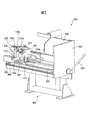
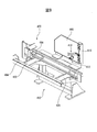
- FIG. 3 is a perspective view of a tool loading station. It is a perspective view of the tool loading station in the replacement tool storage position.
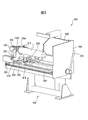
- FIG. 6 is a perspective view of the tool loading station in a separated position.
- FIG. 6 is a perspective view of the tool loading station in the extended position.
- FIG. 6 is a perspective view of the tool loading station with the slider assembly fixed to the base assembly in the extended position.
- FIG. 9 is a perspective view of the tool loading station shown with the tool removed from the tool pot with the tool holder in the extended position.
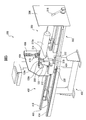
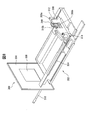
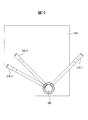
- It is a perspective view of a slider assembly. It is a perspective view of a base assembly. It is a front view which shows the rotation position of a main lever.
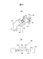
- FIG. 8 is an enlarged perspective view of a part XIV of FIG. 7. It is a partial expansion perspective view which shows a sub lever. It is a flowchart explaining a tool replacement work.
- a tool magazine 100 is disposed adjacent to a machine tool (not shown) such as a vertical or horizontal machining center, and a plurality of workpieces such as end mills used in the machine tool. It is designed to store tools for machining.
- An automatic tool changer (not shown) is arranged between the machine tool and the tool magazine 100, and the tool is changed between the machine tool and the tool magazine 100 by the automatic tool changer.
- the tool magazine 100 has a plurality of struts 106 to 118 erected on a floor surface 104, and a cover 102 surrounding the struts 106 to 118.
- Each of the columns 106 to 118 is formed to detachably attach a plurality of tool pots 120.
- no tool is attached to the tool pot 120, but in reality, one tool T is attached to each tool pot 120 via the tool holder TH (see FIG. 7). ..
- the plurality of columns 106 to 118 form a rack for arranging and holding the tools T and the tool pots 120 in a matrix.
- the tool holder TH can be a tool holder such as a two-face restraint type tool holder (HSK holder) or a BT shank tool holder having a pull stud.
- the tool pot 120 has a tapered hole 120c (FIG. 7) that fits into the tapered portion of the tool holder TH.
- the tool pot 120 has a flange 120a and an engaging groove 120b (see FIGS. 2 to 7) formed in the flange 120a and having a V-shaped cross section.
- the columns (racks) 106 to 118 have pot gripping portions (not shown) that engage with the engaging grooves 120b of the tool pot 120 and hold the tool pot 120.
- the tool T and the tool holder TH are collectively referred to as a tool T.
- a tool loading station 200 for loading the tool T into the tool magazine 100 from the outside and unloading the tool T from the tool magazine 100 to the outside is arranged.
- the operator of the machine tool uses the tool loading station 200 to carry a new tool to be used for machining into the tool magazine 100, or to carry out a tool that is no longer used for machining or a tool that is damaged or worn from the tool magazine 100. Is possible.
- a carrier 130 is further provided in the cover 102 as a tool transfer device.
- the carrier 130 has a tool holding device (not shown) that detachably holds the rear end portion of one tool pot 120.
- the carrier 130 is also movable by at least a vertical plane (a plane parallel to the paper surface of FIG. 1) in two directions orthogonal to the Y axis and the Z axis by a carrier driving device (not shown).
- the tool magazine 100 has a sub arm or a shifter.
- the carrier 130 removes one tool T from the racks 106 to 118 together with the tool pot 120 and conveys it to the sub arm position 124.
- the sub-arm receives the tool T and the tool pot 120 from the carrier 130 and conveys them to the tool change position (not shown) of the automatic tool changer.
- the sub-arm conveys the tool T and the tool pot 120, which the sub-arm has received from the tool exchange position, to the sub-arm position 124, where the carrier 130 receives the tool and the tool pot 120, and places them in the predetermined positions of the racks 106 to 118. Install.
- the carrier 130 allows an operator to carry an arbitrary tool together with the tool pot 120 to the tool loading station 200 by operating an operation panel 122 attached to a side surface of the cover 102 of the tool magazine 100.
- the carrier 130 is adapted to directly attach and detach the tool pot to and from the pot holding member 308 of the tool loading station 200.
- the tool loading station 200 will be described with reference to FIGS. 2 to 12.
- the tool loading station 200 includes a base assembly 400 fixed to the floor surface 104 of the tool magazine 100, and a slider assembly 300 mounted and fixed on the base assembly 400.
- the base assembly 400 includes a leg portion 402 fixed to the floor surface 104 of the tool magazine 100, and a base portion fixed to a pair of front and rear arm portions 420 and 422 horizontally provided on the upper end of the leg portion 402. It has 404 and 406.
- a post 418 is fixed to the base portion 406.
- a partition cover 408 is attached to the post 418 so as to be horizontally rotatable.
- a cam 410 composed of a pair of arm members and a roller 412 are attached.
- Guide rails 414 and 416 extending in the front-rear direction (X-axis direction perpendicular to the paper surface in FIG. 1) are fixed to the base portions 404 and 406.
- the slider assembly 300 has a slider 302 that can slide in the front-rear direction along the guide rails 414 and 416.
- a block (only one block 330 is shown in the drawing) that slides on the guide rails 414 and 416 is attached to the lower surface of the rear end of the slider 302.
- a flat plate-shaped lid 304 is attached to the front end of the slider 302.
- a main lever 316 of the slider assembly 300 is rotatably attached to the outer surface of the lid 304 as a first lever.
- a connecting rod 326 that extends horizontally in the front-rear direction is coupled to the main lever 316.
- a cam device 340 (FIGS. 11 to 14) is attached to the rear end of the connecting rod 326 (end on the magazine side), and the cam device 340 operates in conjunction with the rotation operation of the main lever 316.
- the attachment/detachment device includes a main lever 316, a connecting rod 326, and a cam device 340.
- the main lever 316 can take three positions: an origin position (lock position) 316-1, an unlock position 316-2, and a slider fixing position 316-3. it can.
- the unlock position 316-2 is 90° in the counterclockwise direction from the origin position 316-1
- the slider fixing position is 17° in the counterclockwise direction from the unlock position. be able to.
- a pot holding member 308 and a tool holding member 310 are attached to the upper surface of the rear portion of the slider 302.
- the pot holding member 308 has a recess 308a that receives the flange 120a of the tool pot 120, and a mating portion 308b that is provided in the recess 308a and that mates with the engagement groove 120b of the tool pot 120.
- the pot holding member 308 is arranged on the rear end side of the tool holding member 310 and is fixed so as not to move with respect to the slider 302.
- a roller 314 having a vertical rotation shaft is attached to the pot holding member 308.
- the tool holding member 310 has a circular arc-shaped recess 310a for receiving a flange (not shown) of the tool holder TH, and a blade which is fitted in a circumferential groove (not shown) of the tool holder TH provided in the recess 310a. It has a mating portion 310b.
- the tool holding member 310 is arranged on the front side of the pot holding member 308, and is attached to the slider 302 so as to be slidable in the front-rear direction.
- a pair of rails extending in the front-rear direction (only one rail 318 (FIG. 15) is shown) is attached to the upper surface of the slider 302, and a lower surface of the tool holding member 310 slides on the pair of rails.
- Block 320 (FIG. 15) is attached.
- the slider assembly 300 is provided with a sub-lever 312 of the tool holding member 310 as a second lever.
- the sub-lever 312 is attached to a link member 332 rotatably connected to the tool holding member 310 by a pin 332a, and a finger member 324 is attached to the link member 332.
- the finger member 324 can be engaged with and disengaged from the locking member 322 attached to the upper surface of the slider 302 according to the rotation angle of the sub lever 312.
- the finger member 324 is disengaged from the locking member 322, and the tool holding member 310 can move in the axial direction of the tool T.
- the finger member 324 and the locking member 322 are engaged at a predetermined position by the urging force of a spring (not shown), and the tool holding member 310 is locked to the slider 302. .
- the configuration of the attaching/detaching device for attaching/detaching the tool T to/from the tool pot 120 at the replacement tool storage position will be described with reference to FIGS. 11 to 14.
- the cam device 340 which is the main part of the attachment/detachment device, is provided at the link plate 328 attached to the rear end of the connecting rod 326, the rod 342 connected to the link plate 328, and the tip of the rod 342, and is orthogonal to the axis of the tool T.
- a cam follower holder 346 that slides along a rail 344 laid in the direction in which Has a cam plate 350.
- the cam follower holder 346 is shown by a solid line when the main lever 316 is at the origin position 361-1, and the cam follower holder 346 is shown by a chain double-dash line when the main lever 316 is at the unlock position 316-2. It is shown. That is, the cam follower 348 reciprocates between the locked position 352-1 and the unlocked position 352-2 of the cam groove 352 of the cam plate 350 in conjunction with the rotation operation of the main lever 316.
- the cam follower holder 346 holding the cam follower 348 can move only linearly along the rail 344, when the cam follower 348 moves from the lock position 352-1 of the cam groove 352 to the unlock position 352-2, the cam plate 350 and the tool
- the holding member 310 separates from the pot holding member 308 along the rail 318.
- the lift amount of the cam groove 352 is 20 mm, and the tool T is unclamped when it is separated from the pot holding member 308 by 20 mm.
- the unclamp position 352-2 side of the cam groove 352 is opened in the axial direction of the tool T of the cam groove 352. With this shape, the tool holding member 310 can be moved further forward from the pot holding member 308 when the slider 302 is pulled out. At this time, the cam follower 348 is disengaged from the cam groove 352 (see FIG. 14).
- the operator operates the operation panel 122 for the tool loading station 200 to select a tool to be replaced out of the plurality of tools stored in the tool magazine 100, as shown in FIG.
- the tool T and the tool pot 120 to be replaced are moved to the pot holding member 308 and the tool holding member 310 waiting in the storage position (step S10), and the tool T and the tool pot 120 to be replaced are held by the tool holding member 310 and the pot holding member 308, respectively. (Step S12).
- step S12 the operator rotates the main lever 316 by 90° in the counterclockwise direction from the origin position 316-1 to the unlock position 316-2, as shown in FIG. 4 (step S14). ..
- the link plate 328 rotates, the slider assembly 300 is movable in the front-rear direction with respect to the base assembly 400, and the tool holding member 310 is advanced by a predetermined distance, for example, 20 mm by the cam device 340. , Away from the pot holding member 308.
- the tool T is separated from the tool pot 120.
- the position of the tool holding member 310 at this time is referred to as a separation position.
- both the sliders 302 are pulled out from the tool magazine 100 to the pull-out position outside the tool magazine 100 as shown in FIG. 5 (step S16). While the slider 302 is pulled out, the roller 314 attached to the pot holding member 308 engages with the cam 410 of the partition cover 408 to rotate the partition cover 408 to the closed position shown in FIGS. 5 to 7. ..
- the opening for pulling out the slider assembly 300 from the tool magazine 100 is closed by the partition cover 408, the operator during the tool replacement work is isolated from the inside of the tool magazine 100, and the operator can perform the work safely. ..
- the operator further turns the main lever 316 in the counterclockwise direction by a predetermined angle, for example, 17° from the unlock position 316-2 to the slider fixing position 316-3.
- the slider 302 is fixed to the base portions 404 and 406 (step S18).
- the sub lever 312 rotates about the pin 332a, the finger member 324 is disengaged from the locking member 322, and the tool holding member 310 is moved to the slider 302. It becomes possible to move.
- the operator moves the sub-lever 312 in the direction of the tool T while moving it in the forward direction, whereby the tool holding member 310 moves forward relative to the slider 302 (step S20), and the tool T is moved. It is removed from the tool pot 120 (FIG. 7).
- step S22 the inside of the tapered hole 12c of the tool pot 120 can be cleaned.
- Step S26 After removing the old tool T from the tool holding member 310, the operator fits the tool T equipped with the new tool T into the mating portion 310b of the tool holding member 310, and mounts the new tool T on the tool holding member 310.
- Step S26 The sub lever 312 is rotated to the tool T side to release the engagement between the finger member 324 and the locking member 322, move the tool holding member 310 to the separation position, and return the sub lever 312 (step S28).
- step S30 when the operator rotates the main lever 316 in the clockwise direction from the slider fixing position 316-3 to the unlocking position 316-2 by a predetermined angle, that is, 17° in the present embodiment, the slider 302 moves.
- the lock is released (step S30).
- the slider 302 becomes slidable in the front-back direction.
- the entire slider 302 slides with respect to the base portions 404 and 406, and the entire slider assembly 300 is housed in the tool magazine 100, and the tool holding member. 310 and the pot holding member 308 move to the replacement tool pot position (step 32).
- the roller 314 is disengaged from the cam 410, and the roller 412 of the partition cover 408 is engaged with the flat cam surface 334 of the slider 302 extending in the front-rear direction. Then, the partition cover 408 is opened.
- the main lever 316 is further rotated by a predetermined angle, in the present embodiment, 90° clockwise, to return to the origin position 316-1 of the main lever 316.
- a predetermined angle in the present embodiment, 90° clockwise
- the tool holding member 310 moves toward the pot holding member 308 by a predetermined distance, 20 mm in the present embodiment, and the tapered portion of the tool T fits into the tapered hole 120c of the tool pot 120.
- the tool T is clamped in the tool pot 120 (step S34).
- step S36 After the main lever 316 returns to the origin position 316-1 (Y in step S36), the operator operates the operation panel 122 of the tool loading station to operate the rack 106 corresponding to the address assigned to the new tool T. The new tool T is transferred and attached together with the tool pot 120 to the predetermined positions of 118 through the carrier 130. If the main lever 316 has not completely returned to the origin position 316-1 (NO in step S36), an interlock for prohibiting the transfer of the new tool T by the carrier 130 may be incorporated.
Landscapes
- Engineering & Computer Science (AREA)
- Mechanical Engineering (AREA)
- Automatic Tool Replacement In Machine Tools (AREA)
Abstract
Description
工具ローディングステーションが、工具搬送装置との間で工具を授受する差替え用工具収納位置と、工具マガジンの外部の引出し位置との間で往復移動可能に形成されたスライダと、スライダの工具マガジン側に設けられ、工具ポットを保持するポット保持部材と、スライダにおいてポット保持部材に関して工具マガジンの反対側に設けられ、ポット保持部材に保持された工具ポットに装着されている工具を保持する工具保持部材と、差替え用工具収納位置において、ポット保持部材と工具保持部材とを接近、離反させて、ポット保持部材に保持されている工具ポットから工具を分離させ、ポット保持部材に保持されている工具ポットに工具を装着する着脱装置とを具備する工具マガジンが提供される。
図1において、本発明の好ましい実施形態による工具マガジン100は、立形または横形マシニングセンタのような工作機械(図示せず)に隣接させて配置され、工作機械で使用するエンドミルのような複数のワーク加工用の工具を格納するようになっている。工作機械と工具マガジン100との間には自動工具交換装置(図示せず)が配設され、該自動工具交換装置によって、工作機械と工具マガジン100との間で工具が交換される。
工具ローディングステーション200は、工具マガジン100の床面104に固定されるベース組立体400と、ベース組立体400の上に載置、固定されるスライダ組立体300とを具備している。
まず、オペレータが、工具ローディングステーション200のための操作盤122を操作して、工具マガジン100内に格納されている複数の工具のうち差替えるべき工具を、図3に示すように、差替え用工具収納位置で待機しているポット保持部材308および工具保持部材310の所へ移動させ(ステップS10)、差替えるべき工具Tおよび工具ポット120を、夫々、工具保持部材310およびポット保持部材308に保持させる(ステップS12)。
120 工具ポット
122 操作盤
130 キャリア
200 工具ローディングステーション
300 スライダ組立体
304 閉蓋
308 ポット保持部材
310 工具保持部材
312 サブレバー
316 メインレバー
326 連接棒
328 リンクプレート
340 カム装置
400 ベース組立体
408 仕切りカバー
Claims (4)
- 工具ポットに着脱可能に装着された工具を複数格納する工具マガジンにおいて、
複数の工具の各々を工具ポットと共に保持するラックと、
工具マガジン内で1つの工具を工具ポットと共に搬送する工具搬送装置と、
工具搬送装置との間で工具を授受するように構成された工具ローディングステーションとを具備し、
工具ローディングステーションが、
工具搬送装置との間で工具を授受する差替え用工具収納位置と、工具マガジンの外部の引出し位置との間で往復移動可能に形成されたスライダと、
スライダの工具マガジン側に設けられ、工具ポットを保持するポット保持部材と、
スライダにおいてポット保持部材に関して工具マガジンの反対側に設けられ、ポット保持部材に保持された工具ポットに装着されている工具を保持する工具保持部材と、
差替え用工具収納位置において、ポット保持部材と工具保持部材とを接近、離反させて、ポット保持部材に保持されている工具ポットから工具を分離させ、ポット保持部材に保持されている工具ポットに工具を装着する着脱装置と、
を具備することを特徴とした工具マガジン。 - 着脱装置が、スライダに回動可能に取り付けられたメインレバーと、該メインレバーに連結されたカム機構とを具備する請求項1に記載の工具マガジン。
- スライダが工具引出し位置にあるとき、工具保持部材に保持されている工具の中心軸線に沿ってポット保持部材から離反する方向に、工具保持部材がポット保持部材に対して移動可能に設けられている請求項1に記載の工具マガジン。
- スライダが引出し位置にあるとき、ポット保持部材を工具マガジンの内部の空間から隔離する仕切りカバーを具備する請求項1に記載の工具マガジン。
Priority Applications (4)
| Application Number | Priority Date | Filing Date | Title |
|---|---|---|---|
| CN201980087652.4A CN113272097B (zh) | 2019-01-04 | 2019-01-04 | 刀具库 |
| PCT/JP2019/000038 WO2020141575A1 (ja) | 2019-01-04 | 2019-01-04 | 工具マガジン |
| DE112019006050.3T DE112019006050B4 (de) | 2019-01-04 | 2019-01-04 | Werkzeugmagazin |
| JP2020563856A JP7109594B2 (ja) | 2019-01-04 | 2019-01-04 | 工具マガジン |
Applications Claiming Priority (1)
| Application Number | Priority Date | Filing Date | Title |
|---|---|---|---|
| PCT/JP2019/000038 WO2020141575A1 (ja) | 2019-01-04 | 2019-01-04 | 工具マガジン |
Publications (1)
| Publication Number | Publication Date |
|---|---|
| WO2020141575A1 true WO2020141575A1 (ja) | 2020-07-09 |
Family
ID=71406734
Family Applications (1)
| Application Number | Title | Priority Date | Filing Date |
|---|---|---|---|
| PCT/JP2019/000038 Ceased WO2020141575A1 (ja) | 2019-01-04 | 2019-01-04 | 工具マガジン |
Country Status (4)
| Country | Link |
|---|---|
| JP (1) | JP7109594B2 (ja) |
| CN (1) | CN113272097B (ja) |
| DE (1) | DE112019006050B4 (ja) |
| WO (1) | WO2020141575A1 (ja) |
Citations (3)
| Publication number | Priority date | Publication date | Assignee | Title |
|---|---|---|---|---|
| JP2004268214A (ja) * | 2003-03-10 | 2004-09-30 | Nippei Toyama Corp | 工具交換装置 |
| JP2009066695A (ja) * | 2007-09-12 | 2009-04-02 | Makino Milling Mach Co Ltd | 工具マガジン |
| WO2012032674A1 (ja) * | 2010-09-10 | 2012-03-15 | 株式会社牧野フライス製作所 | 工具差替え装置、工具マガジンおよび工作機械 |
Family Cites Families (9)
| Publication number | Priority date | Publication date | Assignee | Title |
|---|---|---|---|---|
| JP3865092B2 (ja) * | 1997-05-16 | 2007-01-10 | 三井精機工業株式会社 | ケナメタル工具交換装置 |
| JP3337005B2 (ja) * | 1999-06-24 | 2002-10-21 | 豊和工業株式会社 | マシニングセンタの予備工具交換装置 |
| JP3805567B2 (ja) * | 1999-06-29 | 2006-08-02 | 株式会社日平トヤマ | 工具交換方法及びその装置 |
| DE502006001124D1 (de) * | 2006-01-18 | 2008-08-28 | Hueller Hille Gmbh | Werkzeug-Magazin mit einem Speicher-Rad mit zwei Reihen von Werkzeug-Aufnahmen am Umfang |
| JP2008019659A (ja) * | 2006-07-14 | 2008-01-31 | Eito:Kk | 排水口の網袋 |
| DE102009008647A1 (de) * | 2009-02-12 | 2010-09-09 | Deckel Maho Pfronten Gmbh | System zum Wechseln und Einlegen bzw. Vorlegen von Werkzeugen an einer Werkzeugmaschine und Werkzeugmagazin zum Lagern von Werkzeugen |
| JP6006622B2 (ja) * | 2012-11-15 | 2016-10-12 | コマツNtc株式会社 | 工具交換装置および工具交換方法 |
| US10245692B2 (en) * | 2013-11-08 | 2019-04-02 | Makino Milling Machine Co., Ltd. | Chain-type tool magazine |
| TWM530205U (zh) * | 2016-01-27 | 2016-10-11 | New Gifu Entpr Co Ltd | 矩陣式換刀裝置 |
-
2019
- 2019-01-04 JP JP2020563856A patent/JP7109594B2/ja active Active
- 2019-01-04 WO PCT/JP2019/000038 patent/WO2020141575A1/ja not_active Ceased
- 2019-01-04 DE DE112019006050.3T patent/DE112019006050B4/de active Active
- 2019-01-04 CN CN201980087652.4A patent/CN113272097B/zh active Active
Patent Citations (3)
| Publication number | Priority date | Publication date | Assignee | Title |
|---|---|---|---|---|
| JP2004268214A (ja) * | 2003-03-10 | 2004-09-30 | Nippei Toyama Corp | 工具交換装置 |
| JP2009066695A (ja) * | 2007-09-12 | 2009-04-02 | Makino Milling Mach Co Ltd | 工具マガジン |
| WO2012032674A1 (ja) * | 2010-09-10 | 2012-03-15 | 株式会社牧野フライス製作所 | 工具差替え装置、工具マガジンおよび工作機械 |
Also Published As
| Publication number | Publication date |
|---|---|
| DE112019006050T5 (de) | 2021-09-30 |
| JPWO2020141575A1 (ja) | 2021-09-27 |
| CN113272097B (zh) | 2023-06-06 |
| JP7109594B2 (ja) | 2022-07-29 |
| CN113272097A (zh) | 2021-08-17 |
| DE112019006050B4 (de) | 2025-05-08 |
Similar Documents
| Publication | Publication Date | Title |
|---|---|---|
| US20110131791A1 (en) | Machine tool | |
| JP6182413B2 (ja) | 工具着脱装置及び工具マガジン装置 | |
| US4403391A (en) | Machine tool including a tool transfer mechanism | |
| JP2024081917A (ja) | 工具マガジン装置及び工作機械 | |
| KR102086943B1 (ko) | 공작기계 자동공구교환장치용 그리퍼 체인 | |
| WO2020141575A1 (ja) | 工具マガジン | |
| JP3908495B2 (ja) | ボーリングバー支持装置、及び工作機械 | |
| JP5004731B2 (ja) | 工具マガジン | |
| US20230173627A1 (en) | Tool changing device, machine tool and method for changing a tool | |
| US4528742A (en) | Tool-change device for a machine tool | |
| JP3324897B2 (ja) | マシニングセンタ | |
| JP7762611B2 (ja) | 工具マガジン装置 | |
| JP2686164B2 (ja) | タレットパンチプレス | |
| JP2971076B2 (ja) | 工具交換装置の移送装置 | |
| JPH0740175A (ja) | 多軸工作機械の工具交換装置 | |
| JP6655222B1 (ja) | ジョー交換装置、および、工作機械 | |
| KR20220119200A (ko) | 공작기계 공구매거진의 공구 착탈장치 | |
| JPH09300158A (ja) | 工作機械の工具転送装置 | |
| JPH04201147A (ja) | 工作機械における工具自動交換機構 | |
| JP7573096B1 (ja) | 工具搬送装置、及び、加工システム | |
| US20250242461A1 (en) | Tool storage device and bending system | |
| US20240383085A1 (en) | Lateral processing machine and tool changer | |
| SK284034B6 (sk) | Obrábací stroj | |
| JP2980028B2 (ja) | マシニングセンタ | |
| JP3831884B2 (ja) | 自動工具交換装置を備えた工作機械 |
Legal Events
| Date | Code | Title | Description |
|---|---|---|---|
| 121 | Ep: the epo has been informed by wipo that ep was designated in this application |
Ref document number: 19907356 Country of ref document: EP Kind code of ref document: A1 |
|
| ENP | Entry into the national phase |
Ref document number: 2020563856 Country of ref document: JP Kind code of ref document: A |
|
| 122 | Ep: pct application non-entry in european phase |
Ref document number: 19907356 Country of ref document: EP Kind code of ref document: A1 |
|
| WWG | Wipo information: grant in national office |
Ref document number: 112019006050 Country of ref document: DE |