WO2020137784A1 - 流量調整部の遮熱構造 - Google Patents
流量調整部の遮熱構造 Download PDFInfo
- Publication number
- WO2020137784A1 WO2020137784A1 PCT/JP2019/049781 JP2019049781W WO2020137784A1 WO 2020137784 A1 WO2020137784 A1 WO 2020137784A1 JP 2019049781 W JP2019049781 W JP 2019049781W WO 2020137784 A1 WO2020137784 A1 WO 2020137784A1
- Authority
- WO
- WIPO (PCT)
- Prior art keywords
- flow rate
- rate adjusting
- heat shield
- vehicle
- adjusting unit
- Prior art date
- Legal status (The legal status is an assumption and is not a legal conclusion. Google has not performed a legal analysis and makes no representation as to the accuracy of the status listed.)
- Ceased
Links
Images



Classifications
-
- B—PERFORMING OPERATIONS; TRANSPORTING
- B60—VEHICLES IN GENERAL
- B60K—ARRANGEMENT OR MOUNTING OF PROPULSION UNITS OR OF TRANSMISSIONS IN VEHICLES; ARRANGEMENT OR MOUNTING OF PLURAL DIVERSE PRIME-MOVERS IN VEHICLES; AUXILIARY DRIVES FOR VEHICLES; INSTRUMENTATION OR DASHBOARDS FOR VEHICLES; ARRANGEMENTS IN CONNECTION WITH COOLING, AIR INTAKE, GAS EXHAUST OR FUEL SUPPLY OF PROPULSION UNITS IN VEHICLES
- B60K13/00—Arrangement in connection with combustion air intake or gas exhaust of propulsion units
- B60K13/04—Arrangement in connection with combustion air intake or gas exhaust of propulsion units concerning exhaust
-
- B—PERFORMING OPERATIONS; TRANSPORTING
- B60—VEHICLES IN GENERAL
- B60T—VEHICLE BRAKE CONTROL SYSTEMS OR PARTS THEREOF; BRAKE CONTROL SYSTEMS OR PARTS THEREOF, IN GENERAL; ARRANGEMENT OF BRAKING ELEMENTS ON VEHICLES IN GENERAL; PORTABLE DEVICES FOR PREVENTING UNWANTED MOVEMENT OF VEHICLES; VEHICLE MODIFICATIONS TO FACILITATE COOLING OF BRAKES
- B60T17/00—Component parts, details, or accessories of power brake systems not covered by groups B60T8/00, B60T13/00 or B60T15/00, or presenting other characteristic features
-
- B—PERFORMING OPERATIONS; TRANSPORTING
- B60—VEHICLES IN GENERAL
- B60T—VEHICLE BRAKE CONTROL SYSTEMS OR PARTS THEREOF; BRAKE CONTROL SYSTEMS OR PARTS THEREOF, IN GENERAL; ARRANGEMENT OF BRAKING ELEMENTS ON VEHICLES IN GENERAL; PORTABLE DEVICES FOR PREVENTING UNWANTED MOVEMENT OF VEHICLES; VEHICLE MODIFICATIONS TO FACILITATE COOLING OF BRAKES
- B60T17/00—Component parts, details, or accessories of power brake systems not covered by groups B60T8/00, B60T13/00 or B60T15/00, or presenting other characteristic features
- B60T17/04—Arrangements of piping, valves in the piping, e.g. cut-off valves, couplings or air hoses
Definitions
- the present disclosure relates to a heat shield structure of a flow rate adjusting unit.
- Patent Document 1 discloses a structure in which a heat shield plate is eccentrically provided on the side of the exhaust pipe where peripheral devices are arranged.
- Exhaust pipes that pass exhaust gas discharged from the vehicle engine may be installed near the flow rate control unit that controls the flow rate of air supplied to the vehicle brakes. In this case, there is a problem that the exhaust pipe may cause heat damage to the flow rate adjusting unit.
- the present disclosure has been made in view of these points, and it is an object of the present disclosure to provide a heat shield structure of a flow rate adjusting unit that is unlikely to cause heat damage from the exhaust pipe to the flow rate adjusting unit.
- a flow rate adjusting unit that adjusts a flow rate of air supplied to a brake of a vehicle, the flow rate adjusting unit, and an exhaust pipe that passes exhaust gas generated from an engine of the vehicle are provided. And a heat shield for reducing the amount of heat generated by the exhaust pipe transmitted to the flow rate adjuster, and a heat shield structure for the flow rate adjuster.
- the flow rate adjusting section is provided above the exhaust pipe, and the heat shield section is provided between the flow rate adjusting section and the exhaust pipe in a horizontal direction orthogonal to a height direction of the vehicle. You may have the extending main-body board part.
- the heat shield is formed between a plurality of side plate parts extending upward from a side edge of the main body plate part and the plurality of side plate parts, and inside the heat shield part. And an opening for discharging an external object from the.
- a bracket for fixing the flow rate adjusting unit may be further provided on a side frame extending in the front-rear direction of the vehicle, and the heat shield may be fixed to the bracket.
- the bracket extends in the height direction of the vehicle and is fixed to the side frame, and from a lower end of the first fixing portion, an inner side in the vehicle width direction of the vehicle. And a second fixing portion to which the heat shield is fixed, and an upward end from an inner end of the second fixing portion in the vehicle width direction of the vehicle. And a third fixing part having a region and to which the flow rate adjusting part is fixed.
- the present disclosure in the heat shield structure of the flow rate adjusting unit, it is possible to effectively prevent heat damage from the exhaust pipe to the flow rate adjusting unit.
- FIG. 1 shows a state in which a vehicle is provided with a heat shield structure for a flow rate adjusting unit according to the present embodiment.
- FIG. 2 shows a structure in which the vicinity of the heat shield structure of the flow rate adjusting unit is viewed from above when the heat shield structure of the flow rate adjusting unit according to the present embodiment is provided in the vehicle.
- FIG. 3 shows a structure in which the vicinity of the heat shield structure of the flow rate adjusting unit is viewed from the inside of the vehicle when the heat shield structure of the flow rate adjusting unit according to the present embodiment is provided in the vehicle.
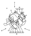
- FIG. 4 shows the structure of the heat shield structure of the flow rate adjusting unit according to the present embodiment.
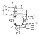
- FIG. 5 shows the structure of the heat shield structure of the flow rate adjusting portion shown in FIG.
- FIG. 6 shows the structure of the heat shield structure of the flow rate adjusting portion shown in FIG.
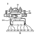
- FIG. 7 shows the structure of the heat shield structure of the flow rate adjusting portion shown in FIG.
- FIG. 1 is a diagram showing a state where a heat shield structure 3 of a flow rate adjusting unit according to the present embodiment is provided in a vehicle.
- FIG. 2 is a diagram showing a structure of the vicinity of the heat shield structure 3 of the flow rate adjusting unit in a state where the heat shield structure 3 of the flow rate adjusting unit according to the present embodiment is provided in the vehicle as viewed from above.
- FIG. 3 is a diagram showing the structure of the vicinity of the heat shield structure 3 of the flow rate adjusting unit when the heat shield structure 3 of the flow rate adjusting unit according to the present embodiment is provided in the vehicle as viewed from the inside of the vehicle.
- the vehicle has a side frame 1, an exhaust pipe 2, and a heat shield structure 3 of a flow rate adjusting unit.
- the side frame 1 is a member extending in the front-rear direction of the vehicle.
- the two side frames 1 are provided in parallel.
- Exhaust pipe 2 passes exhaust gas generated from the engine of the vehicle. One end of the exhaust pipe 2 is connected to an engine (not shown). The hot exhaust gas generated from the engine passes through the exhaust pipe 2 and is exhausted from the other end of the exhaust pipe 2 to the outside of the vehicle.
- the exhaust pipe 2 has a first region 21 and a second region 22.
- the first area 21 is an area extending in the front-rear direction of the vehicle. One end of the first region 21 is connected to the engine (not shown).
- the first region 21 has a region of the two side frames 1 that extends along the right side frame 1 below the right side frame 1 in the vehicle width direction of the vehicle. The vicinity of the rear end of the first region 21 is located below the heat shield structure 3 of the flow rate adjusting unit described later.
- the second area 22 is an area extending from the rear end of the first area 21 in the vehicle width direction of the vehicle.
- the right end of the second region 22 in the vehicle width direction of the vehicle is located near the lower portion of the heat shield structure 3 of the flow rate adjusting unit described later.
- the left end portion of the second region 22 in the vehicle width direction of the vehicle is located, for example, in the lower left portion of the vehicle.
- the heat shield structure 3 of the flow rate adjusting unit blocks heat from the exhaust pipe 2 to the flow rate adjusting unit 31 described later. Specifically, the heat shield structure 3 of the flow rate adjusting unit blocks radiant heat from the exhaust pipe 2 to the flow rate adjusting unit 31 described later. The details of the heat shield structure 3 of the flow rate adjusting unit will be described below.
- FIG. 4 is a diagram showing the structure of the heat shield structure 3 of the flow rate adjusting unit according to the present embodiment.
- 5 is a figure which shows the structure which looked at the heat shield structure 3 of the flow volume adjustment part shown in FIG. 4 from the direction of A.
- FIG. 6 is a view showing the structure of the heat shield structure 3 of the flow rate adjusting unit shown in FIG. 4 as seen from the direction B.
- 7 is a figure which shows the structure which looked at the heat shield structure 3 of the flow volume adjustment part shown in FIG. 4 from the C direction.
- the heat shield structure 3 of the flow rate adjusting unit has a flow rate adjusting unit 31, a heat shield 32, and a bracket 33.
- the flow rate adjusting unit 31 adjusts the flow rate of air supplied to the brake of the vehicle.
- the flow rate adjusting unit 31 is, for example, a relay valve.
- the flow rate adjusting unit 31 has an exhaust port 311.
- the exhaust port 311 discharges air from the flow rate adjusting unit 31.
- the exhaust port 311 is provided at the lower end of the flow rate adjusting unit 31. In the flow rate adjusting unit 31 shown in FIG. 3, the air discharged from the exhaust port 311 is discharged downward, for example.
- the heat shield 32 reduces the amount of heat generated by the exhaust pipe 2 transferred to the flow rate adjuster 31. Specifically, the heat shield 32 shields radiant heat from the exhaust pipe 2 to the flow rate adjuster 31.
- the heat shield 32 is provided between the flow rate adjuster 31 and the exhaust pipe 2. As shown in FIGS. 2 and 3, specifically, the flow rate adjusting unit 31 is provided above the exhaust pipe 2.
- the heat shield 32 has a main body plate 321, a side plate 322, and an opening 326.
- the body plate portion 321 extends between the flow rate adjusting portion 31 and the exhaust pipe 2 in the horizontal direction orthogonal to the height direction of the vehicle.
- the side plate portion 322 extends upward from the side edge of the main body plate portion 321.
- a front side plate portion 323, a left side plate portion 324, and a rear side plate portion 325 are provided as the side plate portion 322.
- the front side plate portion 323 extends upward from the front edge of the main body plate portion 321.
- the left side plate portion 324 extends upward from the left edge of the main body plate portion 321.
- the rear side plate portion 325 extends upward from the rear edge of the main body plate portion 321.
- the opening 326 is formed between the plurality of side plate portions 322, and is an opening for discharging an external object from the inside of the heat shield 32.
- the external object is, for example, water or mud.
- a first opening 327, a second opening 328, and a third opening 329 are provided as the opening 326.
- the first opening 327 is formed between the left end of the front side plate 323 and the front end of the left side plate 324.
- the second opening 328 is formed between the rear end of the left side plate 324 and the left end of the rear side plate 325.
- the third opening 329 is formed between the right end of the front side plate 323 and the right end of the rear side plate 325.
- the opening 326 is formed in the heat shield 32 in the heat shield structure 3 of the flow rate adjusting unit, an external object inside the heat shield 32 is discharged through the opening 326. be able to.
- the heat shield 32 is fixed to the bracket 33.
- the bracket 33 fixes the flow rate adjusting unit 31 to the side frame 1 extending in the front-rear direction of the vehicle.
- the heat shield unit 32 is thus fixed to the bracket 33, so that the flow rate adjusting unit 31 is fixed to the side frame 1 via the bracket 33.
- the heat shield 32 can be attached and detached independently of the adjustment unit 31 and the bracket 33.
- the bracket 33 has a first fixing portion 331, a second fixing portion 332, and a third fixing portion 333.
- the first fixing portion 331 extends in the height direction of the vehicle and is fixed to the side frame 1.
- the second fixing portion 332 extends from the lower end of the first fixing portion 331 toward the inside in the vehicle width direction of the vehicle, and the heat shield 32 is fixed.
- the third fixing portion 333 has a region extending upward from an inner end portion of the second fixing portion 332 in the vehicle width direction of the vehicle, and the flow rate adjusting portion 31 is fixed.
- the heat shield structure 3 of the flow rate adjusting unit has the bracket 33 having the first fixing portion 331, the second fixing portion 332, and the third fixing portion 333 as described above, and thus the first fixing portion 331 and the second fixing portion.
- a pipe, wiring, or the like can be routed in the space formed inside 332 and the third fixing portion 333.
- the heat shield structure 3 of the flow rate adjusting unit includes a flow rate adjusting unit 31 that adjusts a flow rate of air supplied to a brake of a vehicle, a flow rate adjusting unit 31, and an exhaust pipe that passes exhaust gas generated from an engine of the vehicle. 2 and a heat shield 32 that reduces the amount of heat generated by the exhaust pipe 2 transferred to the flow rate adjuster 31.
- the heat shield structure 3 of the flow rate adjusting unit is provided between the flow rate adjusting unit 31 and the exhaust pipe 2 through which the exhaust gas generated from the engine of the vehicle passes, and the exhaust pipe 2 emits the heat. It has a heat shield 32 that reduces the amount of heat transferred to the flow rate adjuster 31. Therefore, the heat shield structure 3 of the flow rate adjusting unit can block the heat from the exhaust pipe 2 to the flow rate adjusting unit 31. As a result, since the heat shield structure 3 of the flow rate adjusting unit can suppress heat damage from the exhaust pipe 2 to the flow rate adjusting unit 31, it is possible to prevent the flow rate adjusting unit 31 from malfunctioning.
- the present disclosure has been described using the embodiments, the technical scope of the present disclosure is not limited to the scope described in the above embodiments, and various modifications and changes are possible within the scope of the gist thereof. is there.
- the specific embodiment of the distribution/integration of the device is not limited to the above-described embodiment, and all or a part of the device may be functionally or physically distributed/integrated in arbitrary units.
- You can Further, a new embodiment generated by an arbitrary combination of a plurality of embodiments is also included in the embodiments of the present disclosure. The effect of the new embodiment produced by the combination has the effect of the original embodiment together.
- the heat shield structure 3 of the flow rate adjusting unit according to the present disclosure can block heat from the exhaust pipe 2 to the flow rate adjusting unit 31.
- the heat shield structure 3 of the flow rate adjusting unit can suppress heat damage from the exhaust pipe 2 to the flow rate adjusting unit 31, it is possible to prevent the flow rate adjusting unit 31 from malfunctioning.
Landscapes
- Engineering & Computer Science (AREA)
- Transportation (AREA)
- Mechanical Engineering (AREA)
- Chemical & Material Sciences (AREA)
- Combustion & Propulsion (AREA)
- Exhaust Silencers (AREA)
- Cooling, Air Intake And Gas Exhaust, And Fuel Tank Arrangements In Propulsion Units (AREA)
- Valves And Accessory Devices For Braking Systems (AREA)
Abstract
流量調整部の遮熱構造3は、車両のブレーキに供給する空気の流量を調整する流量調整部31と、流量調整部31と、車両のエンジンから生じる排気ガスを通す排気管2との間に設けられており、排気管2が発する熱が流量調整部31に伝わる量を低減させる遮熱部32と、を有する。また、流量調整部31は、排気管2の上方に設けられており、遮熱部32は、流量調整部31と排気管2との間において、車両の高さ方向と直交する水平方向において延在している本体板部321を有する。
Description
本開示は、流量調整部の遮熱構造に関する。
車両には、車両のブレーキに供給する空気の流量を調整する流量調整部の遮熱構造が設けられている。特許文献1には、排気管の周辺機器の配置されている側に遮熱板が偏設されている構造が開示されている。
車両のブレーキに供給する空気の流量を調整する流量調整部の付近に車両のエンジンから排出される排気ガスを通す排気管が設けられている場合がある。この場合、排気管から流量調整部に対する熱害が生じるおそれがあるという問題が生じていた。
そこで、本開示はこれらの点に鑑みてなされたものであり、排気管から流量調整部に対する熱害を生じさせづらい流量調整部の遮熱構造を提供することを目的とする。
本開示の第1の態様においては、車両のブレーキに供給する空気の流量を調整する流量調整部と、前記流量調整部と、前記車両のエンジンから生じる排気ガスを通す排気管との間に設けられており、前記排気管が発する熱が前記流量調整部に伝わる量を低減させる遮熱部と、を有することを特徴とする流量調整部の遮熱構造を提供する。
また、前記流量調整部は、前記排気管の上方に設けられており、前記遮熱部は、前記流量調整部と前記排気管との間において、前記車両の高さ方向と直交する水平方向において延在している本体板部を有していてもよい。
また、前記遮熱部は、前記本体板部の側縁から上方に向かって延伸している複数の側板部と、前記複数の側板部の間に形成されており、かつ前記遮熱部の内側から外部の物体を排出するための開口部と、をさらに有していてもよい。
また、前記車両の前後方向において延伸しているサイドフレームに前記流量調整部を固定するブラケットをさらに有し、前記遮熱部は、前記ブラケットに固定されていてもよい。
また、前記ブラケットは、前記車両の高さ方向において延伸しており、かつ前記サイドフレームに固定されている第1固定部と、前記第1固定部の下端から、前記車両の車幅方向における内側に向かって延伸しており、かつ前記遮熱部が固定されている第2固定部と、前記第2固定部の前記車両の車幅方向における内側の端部から上方に向かって延伸している領域を有し、かつ前記流量調整部が固定されている第3固定部と、を有していてもよい。
本開示によれば、流量調整部の遮熱構造において、排気管から流量調整部に対する熱害を生じさせづらくするという効果を奏する。
[流量調整部の遮熱構造3の周辺構成]
図1は、本実施形態に係る流量調整部の遮熱構造3が車両に設けられている状態を示す図である。図2は、本実施形態に係る流量調整部の遮熱構造3が車両に設けられている状態における流量調整部の遮熱構造3付近を上方から見た構造を示す図である。図3は、本実施形態に係る流量調整部の遮熱構造3が車両に設けられている状態における流量調整部の遮熱構造3付近を車両の内側から見た構造を示す図である。
図1は、本実施形態に係る流量調整部の遮熱構造3が車両に設けられている状態を示す図である。図2は、本実施形態に係る流量調整部の遮熱構造3が車両に設けられている状態における流量調整部の遮熱構造3付近を上方から見た構造を示す図である。図3は、本実施形態に係る流量調整部の遮熱構造3が車両に設けられている状態における流量調整部の遮熱構造3付近を車両の内側から見た構造を示す図である。
車両は、サイドフレーム1、排気管2、及び流量調整部の遮熱構造3を有する。サイドフレーム1は、車両の前後方向において延伸している部材である。2本のサイドフレーム1は平行に設けられている。
排気管2は、車両のエンジンから生じる排気ガスを通す。排気管2の一端は、図示しないエンジンに接続されている。エンジンから生じる高温の排気ガスは、排気管2を通って、排気管2の他端から車両の外部に排出される。
図1に示すように、排気管2は、第1領域21、及び第2領域22を有する。第1領域21は、車両の前後方向において延伸している領域である。第1領域21の一端は、図示しないエンジンに接続されている。第1領域21は、2本のサイドフレーム1のうち、車両の車幅方向における右側のサイドフレーム1の下方において、当該右側のサイドフレーム1に沿って延伸している領域を有する。第1領域21の後端付近は、後述する流量調整部の遮熱構造3の下方に位置する。
第2領域22は、第1領域21の後端から車両の車幅方向において延伸している領域である。第2領域22の車両の車幅方向における右側の端部は、後述する流量調整部の遮熱構造3の下方付近に位置する。第2領域22の車両の車幅方向における左側の端部は、例えば車両の左側の下部に位置する。
流量調整部の遮熱構造3は、排気管2から後述する流量調整部31への熱を遮る。具体的には、流量調整部の遮熱構造3は、排気管2から後述する流量調整部31への輻射熱を遮る。以下、流量調整部の遮熱構造3の詳細を説明する。
[流量調整部の遮熱構造3の構造]
図4は、本実施形態に係る流量調整部の遮熱構造3の構造を示す図である。図5は、図4で示す流量調整部の遮熱構造3をAの向きから見た構造を示す図である。図6は、図4で示す流量調整部の遮熱構造3をBの向きから見た構造を示す図である。図7は、図4で示す流量調整部の遮熱構造3をCの向きから見た構造を示す図である。
図4は、本実施形態に係る流量調整部の遮熱構造3の構造を示す図である。図5は、図4で示す流量調整部の遮熱構造3をAの向きから見た構造を示す図である。図6は、図4で示す流量調整部の遮熱構造3をBの向きから見た構造を示す図である。図7は、図4で示す流量調整部の遮熱構造3をCの向きから見た構造を示す図である。
流量調整部の遮熱構造3は、流量調整部31、遮熱部32、及びブラケット33を有する。流量調整部31は、車両のブレーキに供給する空気の流量を調整する。流量調整部31は、例えばリレーバルブである。流量調整部31は、排気ポート311を有する。排気ポート311は、流量調整部31から空気を排出する。排気ポート311は、流量調整部31の下端に設けられている。図3に示す流量調整部31においては、排気ポート311から排出される空気は、例えば、下方に向かって排出される。
遮熱部32は、排気管2が発する熱が流量調整部31に伝わる量を低減させる。具体的には、遮熱部32は、排気管2から流量調整部31への輻射熱を遮る。遮熱部32は、流量調整部31と、排気管2との間に設けられている。図2及び図3に示すように、具体的には、流量調整部31は、排気管2の上方に設けられている。
[遮熱部32の構造]
遮熱部32は、本体板部321、側板部322、及び開口部326を有する。本体板部321は、流量調整部31と排気管2との間において、車両の高さ方向と直交する水平方向において延在している。側板部322は、本体板部321の側縁から上方に向かって延伸している。側板部322として、前方側板部323、左側板部324、及び後方側板部325が設けられている。前方側板部323は、本体板部321の前縁から上方に向かって延伸している。左側板部324は、本体板部321の左縁から上方に向かって延伸している。後方側板部325は、本体板部321の後縁から上方に向かって延伸している。
遮熱部32は、本体板部321、側板部322、及び開口部326を有する。本体板部321は、流量調整部31と排気管2との間において、車両の高さ方向と直交する水平方向において延在している。側板部322は、本体板部321の側縁から上方に向かって延伸している。側板部322として、前方側板部323、左側板部324、及び後方側板部325が設けられている。前方側板部323は、本体板部321の前縁から上方に向かって延伸している。左側板部324は、本体板部321の左縁から上方に向かって延伸している。後方側板部325は、本体板部321の後縁から上方に向かって延伸している。
開口部326は、複数の側板部322の間に形成されており、かつ遮熱部32の内側から外部の物体を排出するための開口部である。外部の物体は、例えば水や泥である。具体的には、開口部326として、第1開口部327、第2開口部328、及び第3開口部329が設けられている。第1開口部327は、前方側板部323の左端と左側板部324の前端との間に形成されている。第2開口部328は、左側板部324の後端と後方側板部325の左端との間に形成されている。第3開口部329は、前方側板部323の右端と後方側板部325の右端との間に形成されている。
流量調整部の遮熱構造3は、このように遮熱部32に開口部326が形成されていることで、遮熱部32の内側の外部の物体を、開口部326を通過させて排出することができる。
遮熱部32は、ブラケット33に固定されている。ブラケット33は、車両の前後方向において延伸しているサイドフレーム1に流量調整部31を固定する。流量調整部の遮熱構造3においては、このように遮熱部32がブラケット33に固定されていることで、流量調整部31がブラケット33を介してサイドフレーム1に固定された状態で、流量調整部31及びブラケット33と独立して遮熱部32を着脱することができる。
ブラケット33は、第1固定部331、第2固定部332、及び第3固定部333を有する。第1固定部331は、車両の高さ方向において延伸しており、かつサイドフレーム1に固定されている。第2固定部332は、第1固定部331の下端から、車両の車幅方向における内側に向かって延伸しており、かつ遮熱部32が固定されている。第3固定部333は、第2固定部332の車両の車幅方向における内側の端部から上方に向かって延伸している領域を有し、かつ流量調整部31が固定されている。
流量調整部の遮熱構造3は、このように第1固定部331、第2固定部332、及び第3固定部333を有するブラケット33を有することで、第1固定部331、第2固定部332、及び第3固定部333の内側に形成される空間にパイプ又は配線等を配索可能となる。
[本実施形態に流量調整部の遮熱構造3による効果]
本実施形態に係る流量調整部の遮熱構造3は、車両のブレーキに供給する空気の流量を調整する流量調整部31と、流量調整部31と、車両のエンジンから生じる排気ガスを通す排気管2との間に設けられており、排気管2が発する熱が流量調整部31に伝わる量を低減させる遮熱部32と、を有する。
本実施形態に係る流量調整部の遮熱構造3は、車両のブレーキに供給する空気の流量を調整する流量調整部31と、流量調整部31と、車両のエンジンから生じる排気ガスを通す排気管2との間に設けられており、排気管2が発する熱が流量調整部31に伝わる量を低減させる遮熱部32と、を有する。
本実施形態に係る流量調整部の遮熱構造3は、このように流量調整部31と、車両のエンジンから生じる排気ガスを通す排気管2との間に設けられており、排気管2が発する熱が流量調整部31に伝わる量を低減させる遮熱部32を有する。よって、流量調整部の遮熱構造3は、排気管2から流量調整部31への熱を遮ることができる。この結果、流量調整部の遮熱構造3は排気管2から流量調整部31に対する熱害を抑制することができるので、流量調整部31を故障させづらくすることができる。
以上、本開示を実施の形態を用いて説明したが、本開示の技術的範囲は上記実施の形態に記載の範囲には限定されず、その要旨の範囲内で種々の変形及び変更が可能である。例えば、装置の分散・統合の具体的な実施の形態は、以上の実施の形態に限られず、その全部又は一部について、任意の単位で機能的又は物理的に分散・統合して構成することができる。また、複数の実施の形態の任意の組み合わせによって生じる新たな実施の形態も、本開示の実施の形態に含まれる。組み合わせによって生じる新たな実施の形態の効果は、もとの実施の形態の効果を合わせ持つ。
本出願は、2018年12月28日付で出願された日本国特許出願(特願2018-247669)に基づくものであり、その内容はここに参照として取り込まれる。
本開示に係る流量調整部の遮熱構造3は、排気管2から流量調整部31への熱を遮ることができる。この結果、流量調整部の遮熱構造3は排気管2から流量調整部31に対する熱害を抑制することができるので、流量調整部31を故障させづらくすることができる。
1・・・サイドフレーム
2・・・排気管
21・・・第1領域
22・・・第2領域
3・・・流量調整部の遮熱構造
31・・・流量調整部
311・・・排気ポート
32・・・遮熱部
321・・・本体板部
322・・・側板部
323・・・前方側板部
324・・・左側板部
325・・・後方側板部
326・・・開口部
327・・・第1開口部
328・・・第2開口部
329・・・第3開口部
33・・・ブラケット
331・・・第1固定部
332・・・第2固定部
333・・・第3固定部
2・・・排気管
21・・・第1領域
22・・・第2領域
3・・・流量調整部の遮熱構造
31・・・流量調整部
311・・・排気ポート
32・・・遮熱部
321・・・本体板部
322・・・側板部
323・・・前方側板部
324・・・左側板部
325・・・後方側板部
326・・・開口部
327・・・第1開口部
328・・・第2開口部
329・・・第3開口部
33・・・ブラケット
331・・・第1固定部
332・・・第2固定部
333・・・第3固定部
Claims (5)
- 車両のブレーキに供給する空気の流量を調整する流量調整部と、
前記流量調整部と、前記車両のエンジンから生じる排気ガスを通す排気管との間に設けられており、前記排気管が発する熱が前記流量調整部に伝わる量を低減させる遮熱部と、
を有することを特徴とする流量調整部の遮熱構造。 - 前記流量調整部は、前記排気管の上方に設けられており、
前記遮熱部は、前記流量調整部と前記排気管との間において、前記車両の高さ方向と直交する水平方向において延在している本体板部を有することを特徴とする、
請求項1に記載の流量調整部の遮熱構造。 - 前記遮熱部は、
前記本体板部の側縁から上方に向かって延伸している複数の側板部と、
前記複数の側板部の間に形成されており、かつ前記遮熱部の内側から外部の物体を排出するための開口部と、
をさらに有することを特徴とする、
請求項2に記載の流量調整部の遮熱構造。 - 前記車両の前後方向において延伸しているサイドフレームに前記流量調整部を固定するブラケットをさらに有し、
前記遮熱部は、前記ブラケットに固定されていることを特徴とする、
請求項1から3のいずれか一項に記載の流量調整部の遮熱構造。 - 前記ブラケットは、
前記車両の高さ方向において延伸しており、かつ前記サイドフレームに固定されている第1固定部と、
前記第1固定部の下端から、前記車両の車幅方向における内側に向かって延伸しており、かつ前記遮熱部が固定されている第2固定部と、
前記第2固定部の前記車両の車幅方向における内側の端部から上方に向かって延伸している領域を有し、かつ前記流量調整部が固定されている第3固定部と、
を有することを特徴とする、
請求項4に記載の流量調整部の遮熱構造。
Priority Applications (2)
| Application Number | Priority Date | Filing Date | Title |
|---|---|---|---|
| CN201980086313.4A CN113226822B (zh) | 2018-12-28 | 2019-12-19 | 流量调节部的隔热结构 |
| PH1/2021/551392A PH12021551392A1 (en) | 2018-12-28 | 2019-12-19 | Heat-insulating structure for flow rate adjusting unit |
Applications Claiming Priority (2)
| Application Number | Priority Date | Filing Date | Title |
|---|---|---|---|
| JP2018-247669 | 2018-12-28 | ||
| JP2018247669A JP2020104794A (ja) | 2018-12-28 | 2018-12-28 | 流量調整部の遮熱構造 |
Publications (1)
| Publication Number | Publication Date |
|---|---|
| WO2020137784A1 true WO2020137784A1 (ja) | 2020-07-02 |
Family
ID=71127644
Family Applications (1)
| Application Number | Title | Priority Date | Filing Date |
|---|---|---|---|
| PCT/JP2019/049781 Ceased WO2020137784A1 (ja) | 2018-12-28 | 2019-12-19 | 流量調整部の遮熱構造 |
Country Status (4)
| Country | Link |
|---|---|
| JP (1) | JP2020104794A (ja) |
| CN (1) | CN113226822B (ja) |
| PH (1) | PH12021551392A1 (ja) |
| WO (1) | WO2020137784A1 (ja) |
Citations (3)
| Publication number | Priority date | Publication date | Assignee | Title |
|---|---|---|---|---|
| JPH03159864A (ja) * | 1989-11-17 | 1991-07-09 | Nissan Motor Co Ltd | ブレーキチューブへの排気管熱遮断構造 |
| JP2008080861A (ja) * | 2006-09-26 | 2008-04-10 | Honda Motor Co Ltd | 自動二輪車 |
| JP2012211556A (ja) * | 2011-03-31 | 2012-11-01 | Daihatsu Motor Co Ltd | 排気経路の遮熱構造 |
Family Cites Families (1)
| Publication number | Priority date | Publication date | Assignee | Title |
|---|---|---|---|---|
| FR3041913B1 (fr) * | 2015-10-05 | 2019-01-25 | Psa Automobiles Sa. | Ensemble pour chassis de vehicule automobile |
-
2018
- 2018-12-28 JP JP2018247669A patent/JP2020104794A/ja active Pending
-
2019
- 2019-12-19 CN CN201980086313.4A patent/CN113226822B/zh active Active
- 2019-12-19 PH PH1/2021/551392A patent/PH12021551392A1/en unknown
- 2019-12-19 WO PCT/JP2019/049781 patent/WO2020137784A1/ja not_active Ceased
Patent Citations (3)
| Publication number | Priority date | Publication date | Assignee | Title |
|---|---|---|---|---|
| JPH03159864A (ja) * | 1989-11-17 | 1991-07-09 | Nissan Motor Co Ltd | ブレーキチューブへの排気管熱遮断構造 |
| JP2008080861A (ja) * | 2006-09-26 | 2008-04-10 | Honda Motor Co Ltd | 自動二輪車 |
| JP2012211556A (ja) * | 2011-03-31 | 2012-11-01 | Daihatsu Motor Co Ltd | 排気経路の遮熱構造 |
Also Published As
| Publication number | Publication date |
|---|---|
| CN113226822A (zh) | 2021-08-06 |
| JP2020104794A (ja) | 2020-07-09 |
| CN113226822B (zh) | 2024-01-30 |
| PH12021551392A1 (en) | 2022-05-16 |
Similar Documents
| Publication | Publication Date | Title |
|---|---|---|
| JP5831111B2 (ja) | 建設機械の排気構造 | |
| JP5867852B2 (ja) | 小型車両のプロテクター付きマフラー装置 | |
| JP2005291121A (ja) | 車両の排気系支持構造 | |
| JPWO2015056347A1 (ja) | 移動車両 | |
| US7617909B2 (en) | Muffler | |
| JP2014141131A (ja) | 車両用空調装置 | |
| JP2005220852A (ja) | 排気系支持構造 | |
| CN204511639U (zh) | 一种车辆用发动机的吸气装置 | |
| CN108778796B (zh) | 车辆空气调节系统 | |
| JP5196113B2 (ja) | 車両用エンジンの吸気装置 | |
| JP2020104794A (ja) | 流量調整部の遮熱構造 | |
| JP2006298181A (ja) | 車両用空調装置 | |
| JP2011084225A (ja) | ウォッシャタンクの取付け車体構造 | |
| JP2004106652A (ja) | エンジン取付け部における防振ゴムの遮熱構造 | |
| JP2006168635A (ja) | 車両前部構造 | |
| JP2019064315A (ja) | 車体下部構造 | |
| JP4784610B2 (ja) | 車両 | |
| JP5316082B2 (ja) | 自動車に搭載される電子コントロールユニットの冷却装置 | |
| KR102249595B1 (ko) | 차량용 에어 클리너 유닛 | |
| JP2014201271A (ja) | 船舶用空調装置 | |
| JP6556587B2 (ja) | 吸気ダクト | |
| JP3101334B2 (ja) | 自動二輪車用排気装置 | |
| WO2020137805A1 (ja) | 空気排出部のガード構造 | |
| KR20200002089A (ko) | 풍량 조절 댐퍼 | |
| JP5979381B2 (ja) | 車両の吸気音伝達装置 |
Legal Events
| Date | Code | Title | Description |
|---|---|---|---|
| 121 | Ep: the epo has been informed by wipo that ep was designated in this application |
Ref document number: 19906474 Country of ref document: EP Kind code of ref document: A1 |
|
| NENP | Non-entry into the national phase |
Ref country code: DE |
|
| 122 | Ep: pct application non-entry in european phase |
Ref document number: 19906474 Country of ref document: EP Kind code of ref document: A1 |