WO2020137218A1 - 緩衝器 - Google Patents
緩衝器 Download PDFInfo
- Publication number
- WO2020137218A1 WO2020137218A1 PCT/JP2019/044551 JP2019044551W WO2020137218A1 WO 2020137218 A1 WO2020137218 A1 WO 2020137218A1 JP 2019044551 W JP2019044551 W JP 2019044551W WO 2020137218 A1 WO2020137218 A1 WO 2020137218A1
- Authority
- WO
- WIPO (PCT)
- Prior art keywords
- cylinder
- outer cylinder
- shock absorber
- end side
- contact
- Prior art date
- Legal status (The legal status is an assumption and is not a legal conclusion. Google has not performed a legal analysis and makes no representation as to the accuracy of the status listed.)
- Ceased
Links
Images




Classifications
-
- F—MECHANICAL ENGINEERING; LIGHTING; HEATING; WEAPONS; BLASTING
- F16—ENGINEERING ELEMENTS AND UNITS; GENERAL MEASURES FOR PRODUCING AND MAINTAINING EFFECTIVE FUNCTIONING OF MACHINES OR INSTALLATIONS; THERMAL INSULATION IN GENERAL
- F16F—SPRINGS; SHOCK-ABSORBERS; MEANS FOR DAMPING VIBRATION
- F16F9/00—Springs, vibration-dampers, shock-absorbers, or similarly-constructed movement-dampers using a fluid or the equivalent as damping medium
- F16F9/32—Details
- F16F9/3271—Assembly or repair
-
- B—PERFORMING OPERATIONS; TRANSPORTING
- B60—VEHICLES IN GENERAL
- B60G—VEHICLE SUSPENSION ARRANGEMENTS
- B60G3/00—Resilient suspensions for a single wheel
- B60G3/02—Resilient suspensions for a single wheel with a single pivoted arm
- B60G3/04—Resilient suspensions for a single wheel with a single pivoted arm the arm being essentially transverse to the longitudinal axis of the vehicle
- B60G3/06—Resilient suspensions for a single wheel with a single pivoted arm the arm being essentially transverse to the longitudinal axis of the vehicle the arm being rigid
-
- B—PERFORMING OPERATIONS; TRANSPORTING
- B60—VEHICLES IN GENERAL
- B60G—VEHICLE SUSPENSION ARRANGEMENTS
- B60G13/00—Resilient suspensions characterised by arrangement, location or type of vibration dampers
- B60G13/001—Arrangements for attachment of dampers
- B60G13/005—Arrangements for attachment of dampers characterised by the mounting on the axle or suspension arm of the damper unit
- B60G13/008—Arrangements for attachment of dampers characterised by the mounting on the axle or suspension arm of the damper unit involving use of an auxiliary cylinder
-
- B—PERFORMING OPERATIONS; TRANSPORTING
- B60—VEHICLES IN GENERAL
- B60G—VEHICLE SUSPENSION ARRANGEMENTS
- B60G3/00—Resilient suspensions for a single wheel
- B60G3/18—Resilient suspensions for a single wheel with two or more pivoted arms, e.g. parallelogram
- B60G3/28—Resilient suspensions for a single wheel with two or more pivoted arms, e.g. parallelogram at least one of the arms itself being resilient, e.g. leaf spring
-
- F—MECHANICAL ENGINEERING; LIGHTING; HEATING; WEAPONS; BLASTING
- F16—ENGINEERING ELEMENTS AND UNITS; GENERAL MEASURES FOR PRODUCING AND MAINTAINING EFFECTIVE FUNCTIONING OF MACHINES OR INSTALLATIONS; THERMAL INSULATION IN GENERAL
- F16F—SPRINGS; SHOCK-ABSORBERS; MEANS FOR DAMPING VIBRATION
- F16F9/00—Springs, vibration-dampers, shock-absorbers, or similarly-constructed movement-dampers using a fluid or the equivalent as damping medium
- F16F9/10—Springs, vibration-dampers, shock-absorbers, or similarly-constructed movement-dampers using a fluid or the equivalent as damping medium using liquid only; using a fluid of which the nature is immaterial
- F16F9/14—Devices with one or more members, e.g. pistons, vanes, moving to and fro in chambers and using throttling effect
- F16F9/16—Devices with one or more members, e.g. pistons, vanes, moving to and fro in chambers and using throttling effect involving only straight-line movement of the effective parts
- F16F9/18—Devices with one or more members, e.g. pistons, vanes, moving to and fro in chambers and using throttling effect involving only straight-line movement of the effective parts with a closed cylinder and a piston separating two or more working spaces therein
- F16F9/185—Bitubular units
-
- F—MECHANICAL ENGINEERING; LIGHTING; HEATING; WEAPONS; BLASTING
- F16—ENGINEERING ELEMENTS AND UNITS; GENERAL MEASURES FOR PRODUCING AND MAINTAINING EFFECTIVE FUNCTIONING OF MACHINES OR INSTALLATIONS; THERMAL INSULATION IN GENERAL
- F16F—SPRINGS; SHOCK-ABSORBERS; MEANS FOR DAMPING VIBRATION
- F16F9/00—Springs, vibration-dampers, shock-absorbers, or similarly-constructed movement-dampers using a fluid or the equivalent as damping medium
- F16F9/32—Details
- F16F9/3207—Constructional features
- F16F9/3235—Constructional features of cylinders
- F16F9/3242—Constructional features of cylinders of cylinder ends, e.g. caps
-
- F—MECHANICAL ENGINEERING; LIGHTING; HEATING; WEAPONS; BLASTING
- F16—ENGINEERING ELEMENTS AND UNITS; GENERAL MEASURES FOR PRODUCING AND MAINTAINING EFFECTIVE FUNCTIONING OF MACHINES OR INSTALLATIONS; THERMAL INSULATION IN GENERAL
- F16F—SPRINGS; SHOCK-ABSORBERS; MEANS FOR DAMPING VIBRATION
- F16F9/00—Springs, vibration-dampers, shock-absorbers, or similarly-constructed movement-dampers using a fluid or the equivalent as damping medium
- F16F9/32—Details
- F16F9/3207—Constructional features
- F16F9/3235—Constructional features of cylinders
- F16F9/3257—Constructional features of cylinders in twin-tube type devices
-
- B—PERFORMING OPERATIONS; TRANSPORTING
- B60—VEHICLES IN GENERAL
- B60G—VEHICLE SUSPENSION ARRANGEMENTS
- B60G13/00—Resilient suspensions characterised by arrangement, location or type of vibration dampers
- B60G13/02—Resilient suspensions characterised by arrangement, location or type of vibration dampers having dampers dissipating energy, e.g. frictionally
- B60G13/06—Resilient suspensions characterised by arrangement, location or type of vibration dampers having dampers dissipating energy, e.g. frictionally of fluid type
- B60G13/08—Resilient suspensions characterised by arrangement, location or type of vibration dampers having dampers dissipating energy, e.g. frictionally of fluid type hydraulic
-
- B—PERFORMING OPERATIONS; TRANSPORTING
- B60—VEHICLES IN GENERAL
- B60G—VEHICLE SUSPENSION ARRANGEMENTS
- B60G2200/00—Indexing codes relating to suspension types
- B60G2200/10—Independent suspensions
- B60G2200/14—Independent suspensions with lateral arms
- B60G2200/142—Independent suspensions with lateral arms with a single lateral arm, e.g. MacPherson type
-
- B—PERFORMING OPERATIONS; TRANSPORTING
- B60—VEHICLES IN GENERAL
- B60G—VEHICLE SUSPENSION ARRANGEMENTS
- B60G2202/00—Indexing codes relating to the type of spring, damper or actuator
- B60G2202/20—Type of damper
- B60G2202/24—Fluid damper
-
- B—PERFORMING OPERATIONS; TRANSPORTING
- B60—VEHICLES IN GENERAL
- B60G—VEHICLE SUSPENSION ARRANGEMENTS
- B60G2204/00—Indexing codes related to suspensions per se or to auxiliary parts
- B60G2204/10—Mounting of suspension elements
- B60G2204/12—Mounting of springs or dampers
- B60G2204/129—Damper mount on wheel suspension or knuckle
-
- B—PERFORMING OPERATIONS; TRANSPORTING
- B60—VEHICLES IN GENERAL
- B60G—VEHICLE SUSPENSION ARRANGEMENTS
- B60G2204/00—Indexing codes related to suspensions per se or to auxiliary parts
- B60G2204/40—Auxiliary suspension parts; Adjustment of suspensions
- B60G2204/43—Fittings, brackets or knuckles
- B60G2204/4304—Bracket for lower cylinder mount of McPherson strut
-
- B—PERFORMING OPERATIONS; TRANSPORTING
- B60—VEHICLES IN GENERAL
- B60G—VEHICLE SUSPENSION ARRANGEMENTS
- B60G2206/00—Indexing codes related to the manufacturing of suspensions: constructional features, the materials used, procedures or tools
- B60G2206/01—Constructional features of suspension elements, e.g. arms, dampers, springs
- B60G2206/40—Constructional features of dampers and/or springs
- B60G2206/41—Dampers
-
- B—PERFORMING OPERATIONS; TRANSPORTING
- B60—VEHICLES IN GENERAL
- B60G—VEHICLE SUSPENSION ARRANGEMENTS
- B60G2800/00—Indexing codes relating to the type of movement or to the condition of the vehicle and to the end result to be achieved by the control action
- B60G2800/16—Running
- B60G2800/162—Reducing road induced vibrations
-
- F—MECHANICAL ENGINEERING; LIGHTING; HEATING; WEAPONS; BLASTING
- F16—ENGINEERING ELEMENTS AND UNITS; GENERAL MEASURES FOR PRODUCING AND MAINTAINING EFFECTIVE FUNCTIONING OF MACHINES OR INSTALLATIONS; THERMAL INSULATION IN GENERAL
- F16F—SPRINGS; SHOCK-ABSORBERS; MEANS FOR DAMPING VIBRATION
- F16F2222/00—Special physical effects, e.g. nature of damping effects
- F16F2222/12—Fluid damping
-
- F—MECHANICAL ENGINEERING; LIGHTING; HEATING; WEAPONS; BLASTING
- F16—ENGINEERING ELEMENTS AND UNITS; GENERAL MEASURES FOR PRODUCING AND MAINTAINING EFFECTIVE FUNCTIONING OF MACHINES OR INSTALLATIONS; THERMAL INSULATION IN GENERAL
- F16F—SPRINGS; SHOCK-ABSORBERS; MEANS FOR DAMPING VIBRATION
- F16F2230/00—Purpose; Design features
- F16F2230/0052—Physically guiding or influencing
- F16F2230/0058—Physically guiding or influencing using inserts or exterior elements, e.g. to affect stiffness
-
- F—MECHANICAL ENGINEERING; LIGHTING; HEATING; WEAPONS; BLASTING
- F16—ENGINEERING ELEMENTS AND UNITS; GENERAL MEASURES FOR PRODUCING AND MAINTAINING EFFECTIVE FUNCTIONING OF MACHINES OR INSTALLATIONS; THERMAL INSULATION IN GENERAL
- F16F—SPRINGS; SHOCK-ABSORBERS; MEANS FOR DAMPING VIBRATION
- F16F2232/00—Nature of movement
- F16F2232/08—Linear
-
- F—MECHANICAL ENGINEERING; LIGHTING; HEATING; WEAPONS; BLASTING
- F16—ENGINEERING ELEMENTS AND UNITS; GENERAL MEASURES FOR PRODUCING AND MAINTAINING EFFECTIVE FUNCTIONING OF MACHINES OR INSTALLATIONS; THERMAL INSULATION IN GENERAL
- F16F—SPRINGS; SHOCK-ABSORBERS; MEANS FOR DAMPING VIBRATION
- F16F2234/00—Shape
- F16F2234/02—Shape cylindrical
Definitions
- the present invention relates to a shock absorber.
- the present application claims priority based on Japanese Patent Application No. 2018-245972 filed in Japan on December 27, 2018, and the content thereof is incorporated herein.
- shock absorber having a cylinder and an outer cylinder that covers the cylinder (for example, see Patent Document 1).
- the present invention provides a shock absorber capable of suppressing improper assembly.
- the shock absorber has a rod having one end protruding to the outside, a cylindrical cylinder, and a bottom part on the other end, and is arranged on the outer peripheral side of the cylinder and includes the cylinder.
- An outer cylinder that forms a reservoir chamber therebetween, a closing member that closes one end side openings of the cylinder and the outer cylinder, an axial direction of the cylinder extending from the bottom portion, and the cylinder from the inner peripheral surface of the outer cylinder.
- a plurality of protrusions that are provided in the circumferential direction of the cylinder so as to protrude inward in the radial direction of the cylinder, and an abutment portion that is provided at the bottom portion and that the other end side end portion of the cylinder abuts.
- the protrusion includes a fitting portion with which the outer circumference of the cylinder fits.
- the length from the one end side end surface of the protruding portion to the abutting portion is the length from the abutting portion of the bottom portion to the one end side end portion of the outer cylinder and the other end side end portion of the cylinder from the aforesaid It is larger than the difference from the length of the closing member to the one end on the outer peripheral side.
- shock absorber it is possible to suppress assembly failure.
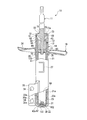
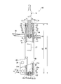
- a shock absorber according to the first embodiment of the present invention will be described below with reference to FIGS. 1 to 6.
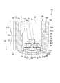
- FIG. 1 shows a shock absorber 10 according to the first embodiment.
- the shock absorber 10 is a shock absorber used for a suspension device of a vehicle such as an automobile or a railway vehicle. Specifically, it is a shock absorber used for a strut suspension of an automobile.
- the shock absorber 10 has a rod 11 whose one end side in the axial direction projects to the outside. In the shock absorber 10, one end side in the axial direction of the rod 11 projects to the outside on one end side in the axial direction of the shock absorber 10.
- the side where the rod 11 in the axial direction of the shock absorber 10 projects (upper side in FIG. 1) is the one end side in the axial direction, and the side where the rod 11 does not project in the axial direction of the shock absorber 10 (lower side in FIG. 1). ) Will be described as the other end side in the axial direction.
- the shock absorber 10 is provided between the cylinder 12 having a bottomed cylindrical shape in which a working liquid as a working fluid is sealed, and a cylinder 12 having a larger diameter than the cylinder 12 on the outer peripheral side of the cylinder 12 as a working fluid. It has a bottomed cylindrical outer cylinder 14 that forms a reservoir chamber 13 in which the working liquid and the working gas are sealed, and a spring seat 16 attached to the outer peripheral side of the outer cylinder 14.
- the outer cylinder 14 is an integrally molded product made of one metal member.
- the outer cylinder 14 is specifically formed by casting an aluminum alloy.
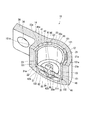
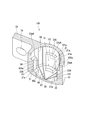
- the outer cylinder 14 includes a cylindrical side wall portion 21, a bottom portion 22 that closes one end side of the side wall portion 21 in the axial direction, and a radial direction of the cylinder 12 from the axial bottom portion 22 side of the inner peripheral surface 21 a of the side wall portion 21.
- a protrusion 23 that protrudes inward, an opening 25 on the side opposite to the axial bottom 22 of the side wall 21, and an outer side in the radial direction of the side wall 21 from the axial bottom 22 side of the side wall 21.
- a stabilizer bracket portion 27 extending outward in the radial direction of the side wall portion 21 from the opening 25 side of the main bracket portion 26 in the axial direction of the side wall portion 21.
- the inner peripheral surface 21 a of the side wall portion 21 is the inner peripheral surface of the outer cylinder 14. Therefore, the protruding portion 23 protrudes from the inner peripheral surface of the outer cylinder 14 toward the radially inner side of the outer cylinder 14.
- the outer cylinder 14 has an opening 25 at one end in the axial direction and a bottom 22 at the other end in the axial direction.
- the bottom portion 22 has a bottom body portion 30 that closes the other end side of the side wall portion 21 in the axial direction, and an abutting portion 31 that projects from the bottom body portion 30 toward one end side in the axial direction.
- the bottom body portion 30 has a spherical plate shape that is curved so as to be convex toward the other end side in the axial direction.
- the contact portion 31 projects from the bottom surface 30a of the bottom body portion 30 to one end side in the axial direction.
- the cylinder 12 is in contact with the contact portion 31 of the bottom portion 22.
- the outer cylinder 14 has a side wall portion 21, a bottom portion 22 including a bottom portion main body portion 30 and a contact portion 31, a protrusion portion 23, a main bracket portion 26, and a stabilizer bracket portion 27, which are formed by casting during casting.
- the other axial end of the bottom body portion 30 does not have to be a spherical plate shape that is curved so as to form a convex shape, and may be a flat plane plate shape or any other shape.
- a plurality of mounting holes 34 are formed in the main bracket portion 26, and the shock absorber 10 has a fastener (not shown) into which the main bracket portion 26 is inserted into these mounting holes 34. ) Is connected to the wheel side. In the shock absorber 10, the rod 11 is connected to the vehicle body side.
- the stabilizer bracket portion 27 is a portion that supports a stabilizer (not shown).
- the spring seat 16 is attached to the side wall 21 closer to the opening 25 than the stabilizer bracket 27.
- the spring seat 16 is made of metal and is fixed to the outer peripheral portion of the side wall portion 21 of the outer cylinder 14 by welding.
- the spring seat 16 has a spring seat fitting portion 35 that fits on the outer peripheral surface of the side wall portion 21, and a receiving portion 36 that extends radially outward from the entire circumference of the spring seat fitting portion 35.
- the spring seat 16 receives the lower end of a spring (not shown) that supports the vehicle body at the receiving portion 36.
- the spring seat 16 may be fixed to the outer cylinder 14 by press fitting or any other fixing method instead of welding to the outer peripheral portion of the side wall portion 21 of the outer cylinder 14.
- the cylinder 12 is an integrally molded product made of one metal member.
- the cylinder 12 has a cylinder main body 41 having a cylindrical shape and a body 42 provided on the cylinder main body 41 so as to close the other end side in the axial direction, and has a bottomed cylindrical shape.
- An opening 43 is formed on the side of the cylinder body 41 opposite to the body 42.
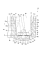
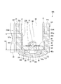
- the body 42 is also an integrally molded product made of one metal member and is formed by sintering. As shown in FIG. 2, the body 42 has a stepped shape having an outer peripheral side having a small diameter portion 45 on one end side in the axial direction and a large diameter portion 46 having a larger diameter on the other end side in the axial direction.
- the small diameter portion 45 and the large diameter portion 46 are formed coaxially.
- the end of the cylinder body 41 on the other end side in the axial direction is fitted into the small diameter portion 45 of the body 42 and is in contact with the large diameter portion 46. In this way, the body 42 is attached to the end of the cylinder body 41 on the other end side in the axial direction.
- the outer diameter of the large diameter portion 46 is smaller than the outer diameter of the cylinder body 41.
- the outer diameter of the large diameter portion 46 may be larger than the outer diameter of the cylinder body 41.
- the shock absorber 10 has a closing member 51 that closes the opening 43 at one end in the axial direction of the cylinder 12 and the opening 25 at one end in the axial direction of the outer cylinder 14.
- the closing member 51 is disposed on the side opposite to the bottom portion 22 with respect to the rod guide 52 and the annular rod guide 52 fitted to one axial end side of both the cylinder 12 and the outer cylinder 14.
- a ring-shaped seal member 53 fitted to one end side in the axial direction.
- the rod guide 52 includes a cylinder fitting portion 61 on the other end side in the axial direction that fits into the cylinder 12, and an outer cylinder fitting portion 62 on the one end side in the axial direction that fits into the outer cylinder 14 and has a larger outer diameter. It has a stepped shape with and.
- the cylinder fitting portion 61 and the outer cylinder fitting portion 62 are formed coaxially.
- the body 42 side of the cylinder body 41 is fitted inside the protruding portion 23 of the outer cylinder 14.
- the body 42 contacts the contact portion 31 of the bottom portion 22 of the outer cylinder 14.
- the opening 12 of the cylinder 12 is fitted into the cylinder fitting portion 61 of the rod guide 52.
- the rod guide 52 is fitted in the outer cylinder fitting portion 62 on the opening 25 side of the side wall portion 21 of the outer cylinder 14.
- the cylinder 12 is supported by the outer cylinder 14 via the rod guide 52.
- the cylinder 12 is coaxially arranged with respect to the outer cylinder 14 and is positioned so as not to move in the radial direction.
- the outer cylinder 14 is formed with a crimp portion 55 that is plastically deformed radially inward by curling, opposite to the bottom portion 22 of the side wall portion 21.
- the cylinder 12 is in contact with the contact portion 31 of the bottom portion 22 of the outer cylinder 14 in the body 42 thereof.
- the rod guide 52 fitted in the cylinder 12 is axially positioned with respect to the outer cylinder 14.
- the seal member 53 is sandwiched between the rod guide 52 axially positioned with respect to the outer cylinder 14 and the caulking portion 55 of the outer cylinder 14.
- the sealing member 53 seals the opening 25 side of the outer cylinder 14.
- the shock absorber 10 has a piston 65 provided in the cylinder body 41 of the cylinder 12 arranged in the outer cylinder 14.
- the piston 65 is slidably fitted in the cylinder body 41.
- the piston 65 defines a first chamber 68 and a second chamber 69 inside the cylinder 12.
- the first chamber 68 is provided between the piston 65 in the cylinder 12 and the rod guide 52.
- the second chamber 69 is provided between the piston 65 in the cylinder 12 and the body 42.
- the second chamber 69 in the cylinder 12 is defined as the reservoir chamber 13 by the body 42 provided on the other end side of the cylinder 12 in the axial direction.
- the first chamber 68 and the second chamber 69 are filled with an oil liquid that is a working liquid.
- the reservoir chamber 13 is filled with a gas that is a working gas and an oil liquid that is a working liquid.
- the other end of the rod 11 in the axial direction is connected to the piston 65, and one end in the axial direction extends from the cylinder 12 and the outer cylinder 14 to the outside through the openings 43 and 25.
- the rod 11 extends from the cylinder 12 and the outer cylinder 14 to the outside through the rod guide 52 and the seal member 53. Radial movement of the rod 11 is restricted by the rod guide 52, and the rod 11 moves in the axial direction integrally with the piston 65 with respect to the cylinder 12 and the outer cylinder 14.
- the seal member 53 closes the gap between the outer cylinder 14 and the rod 11 to prevent the working liquid in the cylinder 12 and the working gas and working liquid in the reservoir chamber 13 from leaking to the outside.
- the seal member 53 is provided in the opening 25 of the outer cylinder 14 and seals the working fluid sealed in the outer cylinder 14.
- the seal member 53 has an inner peripheral side seal portion 71 that is in sliding contact with the rod 11 and an outer peripheral side seal portion 72 that fits into the outer cylinder 14.
- the seal member 53 contacts the caulking portion 55 at the end surface 73a of the end portion 73 (one end portion on the outer peripheral side of the closing member) on the one end side in the axial direction of the outer peripheral side seal portion 72.
- the piston 65 is provided with a passage 75 and an unillustrated passage that penetrate in the axial direction.
- the passage 75 and a passage can connect the first chamber 68 and the second chamber 69.
- the shock absorber 10 has an annular disc valve 77 capable of closing the passage 75 by coming into contact with the piston 65 on the side opposite to the axial bottom 22 of the piston 65. Further, the shock absorber 10 has an annular disc valve 78 capable of closing a passage (not shown) by coming into contact with the piston 65 on the side of the bottom portion 22 in the axial direction of the piston 65.
- the rod 11 moves to the contraction side that increases the amount of entry into the cylinder 12 and the outer cylinder 14, and the piston 65 moves in the direction to narrow the second chamber 69 so that the pressure in the second chamber 69 becomes the first.
- the passage 75 is opened to generate the damping force.
- the rod 11 moves to the extension side that increases the amount of protrusion from the cylinder 12 and the outer cylinder 14, and the piston 65 moves in the direction that narrows the first chamber 68, so that the pressure in the first chamber 68 changes to the second chamber.
- a passage (not shown) is opened to generate a damping force.
- the body 42 of the cylinder 12 is formed with a through hole 81 penetrating in the axial direction at the center in the radial direction.
- a passage 82 and a passage (not shown) are formed outside the through hole 81 in the radial direction.
- the passage 82 and a passage (not shown) allow the second chamber 69 and the reservoir chamber 13 to communicate with each other.
- the shock absorber 10 has an annular disc valve 85 on the axially bottom 22 side of the body 42 and an annular disc valve 86 on the opposite side of the body 42 from the axial bottom 22. There is.
- the disc valve 85 can close the passage 82 by contacting the body 42.
- the disc valve 86 can close a passage (not shown) by contacting the body 42.
- a fastener 88 for attaching the disc valves 85 and 86 to the body 42 is attached to the body 42 through the through hole 81.
- the disc valve 85 when the rod 11 moves toward the contraction side, the piston 65 moves in the direction of narrowing the second chamber 69, and the pressure of the second chamber 69 becomes higher than the pressure of the reservoir chamber 13 by a predetermined value or more, the passage 82 is formed. Open to generate damping force.
- the disc valve 86 opens a passage (not shown) when the rod 11 moves to the extension side, the piston 65 moves to the first chamber 68 side, and the pressure of the second chamber 69 becomes lower than the pressure of the reservoir chamber 13, but At this time, the working liquid is allowed to flow from the reservoir chamber 13 into the second chamber 69 without substantially generating a damping force. That is, the disc valve 86 is a suction valve.
- the outer cylinder 14 has the above-mentioned protruding portion 23 protruding from the inner peripheral surface 21 a of the side wall portion 21 inward in the radial direction of the side wall portion 21.
- the protruding portion 23 extends from the bottom portion 22 of the outer cylinder 14 in the axial direction of the side wall portion 21.
- the outer cylinder 14 is provided with a plurality of projecting portions 23 at equal intervals in the circumferential direction of the side wall portion 21, specifically, four locations.
- the projecting portion 23 has an inner end portion in the radial direction of the side wall portion 21 that serves as a fitting portion 101 as a fitting portion of the present invention in which the outer periphery of the cylinder 12 is fitted.
- the inner end surface 101a of the side wall portion 21 on the side of the central axis extends on the same tapered surface that is inclined about the central axis of the side wall portion 21 by an amount corresponding to the gradient for die cutting.
- the plurality of fitting portions 101 are arranged such that their inner end surfaces 101a are equidistant from the central axis of the side wall portion 21.
- the tapered surface is inclined so that the side closer to the bottom 22 is closer to the central axis of the side wall 21.
- the tapered surface is a conical surface having a smaller diameter on the bottom 22 side.
- the fitting between the cylinder 12 and the fitting portion 101 is not limited to the tight fitting, but may be the clearance fitting.
- the tolerance range of the positions of the cylinder 12 and the protruding portion 23 is a range in which the cylinder 12 can be aligned with the outer cylinder 14 and positioned in the radial direction.
- some of the plurality of protrusions 23 have an end face 23a at one end in the axial direction.
- Each of the end surfaces 23a is centered on the central axis of the side wall portion 21 and extends from the inner end surface 101a of the fitting portion 101 of the protruding portion 23 toward the inner peripheral surface 21a of the side wall portion 21, that is, the inner peripheral surface of the outer cylinder 14. It is arranged on the extending tapered surface. These tapered surfaces are inclined so that the inner end surface 101a side of the fitting portion 101 is located on the other end side in the axial direction.
- the end surface 23a is aligned with the axial center position.
- the center of the end face 23a in the axial direction is arranged at a position equidistant from the bottommost position of the bottom face 30a on the most other end side in the axial direction.
- the end surface 23 a is a tapered surface extending from the fitting portion 101 of the protruding portion 23 toward the inner peripheral surface of the outer cylinder 14.
- the bottom portion 22 of the outer cylinder 14 is formed with the above-mentioned contact portion 31 with which the end portion 102 (the other end side end portion of the cylinder) of the body 42, which is the end portion on the other end side in the axial direction of the cylinder 12, contacts.
- the cylinder 12 has a contact surface 42a and an end surface 42b formed on the end portion 102.
- the contact portion 31 is formed continuously with the projecting portion 23 so as to project more radially inward of the side wall portion 21 than the projecting portion 23, and extends from the bottom surface 30 a of the bottom body portion 30 to the shaft. It is formed so as to extend toward one end in the direction.
- the contact portion 31 is formed to extend toward the one end side in the axial direction of the bottom portion 22.
- the outer cylinder 14 has a plurality of contact portions 31 spaced apart at equal intervals in the circumferential direction of the side wall portion 21, specifically, four locations which are the same number as the protruding portions 23, and the phases of the corresponding protruding portions 23. It is also provided.
- An end surface 31a of each of the plurality of abutting portions 31 on one axial side thereof is arranged on the same plane orthogonal to the central axis of the side wall portion 21. It should be noted that the contact portions 31 do not have to be provided at four locations, but may be provided in plurality.
- the outer cylinder 14 has a plurality of ribs 95 that are continuous from the side wall portion 21 to the bottom body portion 30.
- the ribs 95 and the contact portion 31 are continuous with each other. It is formed between and.
- the rib 95 includes a convex portion 96 that projects radially inward from the inner peripheral surface 21 a of the side wall portion 21 and a convex portion 97 that protrudes from the bottom surface 30 a of the bottom portion main body portion 30 toward one end in the axial direction as a convex portion of the present invention. And have.
- the convex portion 96 formed on the side wall portion 21 extends along the central axis of the side wall portion 21.
- the convex portion 97 formed on the bottom body portion 30 extends along the radial direction of the bottom body portion 30.
- the plurality of protrusions 97 provided on the bottom portion 22 radially spread from the radial center of the bottom body portion 30.
- the inner end surface 101 a of the fitting portion 101 of the plurality of protrusions 23 is arranged on the inner side in the radial direction of the side wall portion 21 than the entire convex portion 96.
- the end faces 31a of the plurality of contact portions 31 are arranged closer to the one end in the axial direction than the entire convex portion 97.
- the inner end surface 101 a of the fitting portion 101 of each of the plurality of protrusions 23 abuts on the outer peripheral surface 41 a of the cylinder body 41 of the cylinder 12, and the cylinder 12 is moved to the outer cylinder 14. It is positioned so that it cannot move in the radial direction. Further, the outer cylinder 14 positions the cylinder 12 so as to be immovable in the axial direction by the end surfaces 31a of the plurality of contact portions 31 contacting the end portions 102 of the body 42 of the cylinder 12.
- the protruding portion 23 of the outer cylinder 14 projects from the inner peripheral surface of the outer cylinder 14 inward in the radial direction of the cylinder 12. Further, the protruding portion 23 extends from the bottom portion 22 of the outer cylinder 14 in the axial direction of the cylinder 12. Further, the outer cylinder 14 is provided with a plurality of protrusions 23 spaced apart at equal intervals in the circumferential direction of the cylinder 12. The inner end of the protrusion 23 in the radial direction of the cylinder 12 is a fitting portion 101 with which the outer periphery of the cylinder 12 is fitted.
- the same tapered surface on which the inner end surfaces 101a of the plurality of fitting portions 101 are arranged is inclined so that the bottom portion 22 side is closer to the central axis of the cylinder 12.
- the inner ends 101a of the plurality of fitting portions 101 are arranged at positions equidistant from the center axis of the cylinder 12.
- the plurality of inner end surfaces 101a come into contact with the outer peripheral surface 41a of the cylinder body 41 of the cylinder 12 to position the cylinder 12 immovably in the radial direction of the cylinder 12 with respect to the outer cylinder 14.
- the protrusions 23 are provided at least at three positions at equal intervals in the circumferential direction of the cylinder 12.
- the contact portion 31 is formed continuously with the projecting portion 23 so as to project more radially inward of the cylinder 12 than the projecting portion 23, and the abutment portion 31 extends from the bottom surface 30 a of the bottom body portion 30 to the cylinder 12. It is formed so as to extend to one end side in the axial direction. In other words, the contact portion 31 is formed on the bottom portion 22 so as to extend toward one axial end of the cylinder 12.
- a plurality of abutting portions 31 are provided on the outer cylinder 14 at equal intervals in the circumferential direction of the cylinder 12.
- the end surfaces 31a of the plurality of contact portions 31 on the one axial end side are arranged on the same plane orthogonal to the central axis of the cylinder 12.
- the passage 121 between the protruding portion 23 and the abutting portion 31 and the protruding portion 23 and the abutting portion 31 that are adjacent to the protruding portion 23 and the abutting portion 31 in the circumferential direction of the cylinder 12 has the body 42 and the bottom body portion 30.
- the chamber 122 between the cylinder 12 and the side wall portion 21 of the outer cylinder 14 is always communicated with the chamber 122.
- a plurality of passages 121, specifically, four passages 121, a chamber 122, and a chamber 123 form a reservoir chamber 13.
- the ribs 95 between the protruding portions 23 and between the contact portions 31 are formed so as to protrude radially inward of the cylinder 12 rather than the inner peripheral surface 21a.
- the contact portion 31 is provided between the convex portions 97 adjacent to each other in the circumferential direction of the cylinder 12.
- the protrusion 23 is provided between the protrusions 96 adjacent to each other in the circumferential direction of the cylinder 12.
- the contact surface 42 a of the end portion 102 that contacts the end surface 31 a of the contact portion 31 is formed on the same plane over the entire circumference of the body 42. ..
- the contact surface 42a is also formed on the same plane as the end surface 42b on the other end in the axial direction that is located radially inward of the body 42.
- the body 42 contacts the disc valve 85 at the radially inner end face 42b, and the inner peripheral side of the disc valve 85 is pressed by the fastener 88 to the radially inner end face 42b.
- the outer cylinder 14 is formed by gravity casting in which the molten metal is poured into the mold by gravity.
- the cavity forming the bottom portion 22 side is arranged above the cavity forming the side wall portion 21 side.
- a core for forming the inner peripheral surface 21a of the side wall portion 21, the plurality of protruding portions 23, the plurality of contact portions 31, and the bottom surface 30a of the bottom body portion 30 is arranged in the mold.
- a plurality of grooves for extending the gas in the cavity when pouring the molten metal into the cavity are formed extending vertically.
- the ribs 95 are formed by solidifying the molten metal that has entered these grooves. In other words, the rib 95 is a transfer mark of a groove for degassing during casting.
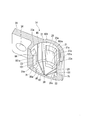
- the outer cylinder 14 is molded by gravity casting as described above in a state before the caulking portion 55 is formed in the opening 25 (hereinafter referred to as before caulking), as shown in FIG.
- the caulking portion 55 has a cylindrical shape in which the side wall portion 21 is extended as it is before being formed.
- the cylinder body 41 is fitted to the body 42 with the disc valves 85 and 86 attached by the fasteners 88, and the cylinder 12 is preassembled.
- a piston 65 attached to the rod 11 together with the disc valves 77 and 78 is fitted in the cylinder 12.
- the rod guide 52 is fitted into the cylinder fitting portion 61 on the other end side in the axial direction of the cylinder 12 so that the rod 11 is inserted inside, and the rod guide 52 is inserted inside the other end side in the axial direction of the rod guide 52.
- a seal member 53 is arranged so as to be inserted into the.
- the caulking portion 55 is formed on the opening portion 25 side of the outer cylinder 14 while pressing the seal member 53, the rod guide 52, and the cylinder 12 toward the bottom portion 2 with a predetermined axial force.
- the fixing step of fixing the seal member 53 and the rod guide 52 to the specified position of the outer cylinder 14 is performed.
- the specified position of the outer cylinder 14 is the position where the seal member 53 and the rod guide 52 are arranged in the shock absorber 10 as a finished product.
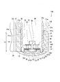
- h3 is defined as the length from the end surface 31a of the contact portion 31 to the end surface 111a of the end portion 111 (one end side end portion of the outer cylinder) on one axial side of the outer cylinder 14 before caulking
- h2 is It is assumed that the length is from the contact surface 42a of the end portion 102 on the other end side in the axial direction of the cylinder 12 to the end surface 73a of the end portion 73 on the one end side in the axial direction of the outer peripheral side seal portion 72 of the seal member 53. Then, in the assembly process before the fixing process, as shown in FIG. 6, when the cylinder 12 and the closing member 51 including the rod guide 52 and the seal member 53 are assembled in the outer cylinder 14 before caulking, h3 is longer than h2.
- h3 is a length from the end surface 31a of the contact portion 31 of the bottom portion 22 to the end surface 111a of the end portion 111 of the outer cylinder 14 on the one axial side
- h2 is the end portion on the other axial side of the cylinder 12.
- the end surface 73a of the outer peripheral side seal portion 72 of the seal member 53 is the same as before the caulking. It is located on the opposite side of the bottom portion 22 from the end surface 111 a on the one axial end side of the cylinder 14. Therefore, it becomes physically difficult to form the crimp portion 55 on the outer cylinder 14.
- Patent Document 1 describes a shock absorber having a cylinder and an outer cylinder that covers the cylinder.
- a caulking portion is formed on the side of the outer cylinder opposite to the lower cap, and the caulking portion and the lower cap sandwich the cylinder, the valve case, and the rod guide.
- the cylinder is radially positioned with respect to the bottom side of the outer cylinder while forming the reservoir chamber by forming a plurality of projecting portions radially inwardly projecting on the bottom side of the outer cylinder. ..
- the cylinder may come into contact with the side opposite to the bottom portion of the protruding portion and stop when assembled to the outer cylinder. If the outer cylinder is caulked in this state, the assembled state of the cylinder to the outer cylinder will be poor.
- h3 is provided in the outer cylinder 14 before caulking, the cylinder 12, the rod guide 52, and the seal member 53.
- the length from the end surface 31a of the abutting portion 31 of the bottom portion 22 to the end surface 111a of the end portion 111 on the one axial end of the outer cylinder 14 when assembled with the closing member 51 consisting of h2, and h2 is the axis of the cylinder 12.
- the end surface 73a of the outer peripheral side seal portion 72 of the seal member 53 is the same as before the caulking. It is located on the opposite side of the bottom portion 22 from the end surface 111 a on the one axial end side of the cylinder 14. Therefore, it becomes physically difficult to form the crimp portion 55 on the outer cylinder 14. Therefore, it is possible to suppress defective assembly of the cylinder 12, the rod guide 52, and the seal member 53 to the outer cylinder 14.
- the rod guide 52 aligns the opening portion 25 side and Together with the radial positioning, the cylinder 12 can be properly and stably arranged with respect to the outer cylinder 14. Therefore, when the lateral force is input to the shock absorber 10, the cylinder 12 is unlikely to shift with respect to the outer cylinder 14, and stable damping force characteristics can be obtained.
- the cylinder 12 is composed of a cylinder body 41 and a body 42 provided at the other axial end portion of the cylinder body 41. Therefore, in the body 42, the contact portion 31 can be stably contacted.
- the chamber 122 between the body 42 and the bottom body portion 30 is formed on the outer cylinder 14 side, and the side wall of the cylinder 12 and the outer cylinder 14 is formed.
- a passage 121 which is always communicated with the chamber 123 between the portion 21 and the reservoir chamber 13, is formed. Therefore, it is not necessary to provide the body 42 with a leg portion for forming a similar passage.
- the contact surface 42a that contacts the contact portion 31 of the body 42 can be formed on the same plane as the end surface 42b of the body 42 that is radially inward and on the other end side in the axial direction.
- the contact portion 31 is formed continuously with the protrusion 23 so as to protrude more radially inward of the cylinder 12 than the protrusion 23, and extends toward the axial end of the cylinder 12 at the bottom 22. ing. Therefore, the outer cylinder 14 is easily manufactured.
- the end surface 23a of the protruding portion 23 on the one end side in the axial direction is a taper surface extending from the fitting portion 101 of the protruding portion 23 toward the inner peripheral surface of the outer cylinder 14, the body 42 of the cylinder 12 has a protruding portion. It is difficult to come into contact with the end face 23a of the contact lens 23 and stop. Therefore, proper assembly of the cylinder 12 to the outer cylinder 14 is facilitated.
- the protrusions 23 are provided at four places, which is three or more, the radial positioning of the cylinder 12 with respect to the outer cylinder 14 can be performed more appropriately.
- a plurality of convex portions 97 radially formed in the radial direction of the cylinder 12 are formed for degassing during casting. It is provided between the convex portions 97 adjacent to each other in the direction. Therefore, the cylinder 12 can be brought into contact with the contact portion 31 while avoiding the convex portion 97. Therefore, the cylinder 12 can be stably seated on the outer cylinder 14 by surface contact.
- the inner peripheral surface 21a of the side wall portion 21 is also formed with a plurality of protrusions 96 extending in the axial direction of the cylinder 12 for the purpose of venting gas during casting. It is provided between the protrusions 96 adjacent to each other in the circumferential direction of the cylinder 12. Therefore, the cylinder 12 can be fitted to the plurality of protrusions 23 while avoiding the protrusions 96. Therefore, the cylinder 12 can be stably positioned with respect to the outer cylinder 14 in the radial direction.
- an outer cylinder 14A that is partially different from the outer cylinder 14 of the first embodiment is used.
- the outer cylinder 14A has a plurality of, more specifically, four protruding portions 23A, which are partially different from the protruding portions 23 of the first embodiment, and each of the protruding portions 23A has an end face 23aA on one axial side. It is different from the end face 23a of the first embodiment. All of these end faces 23aA are in a planar shape and are arranged on the same plane orthogonal to the central axis of the side wall portion 21.
- all the end faces 23aA are arranged at positions equidistant from the bottommost position of the bottom face 30a on the other end side in the axial direction.
- the contact portions 31 do not have to be provided at four locations, and may be provided in plurality.
- h3 is the length from the end surface 31a of the contact portion 31 of the bottom portion 22 to the end surface 111a of the end portion 111 of the outer cylinder 14A on the one axial end side
- h2 is the cylinder 12
- the length from the contact surface 42a of the end portion 102 on the other end side in the axial direction to the end surface 73a of the end portion 73 on the one end side in the axial direction of the outer peripheral side seal portion 72 of the seal member 53 is set before the fixing step
- the rod guide 52 and the seal member 53 are assembled in the outer cylinder 14A before caulking, from the end surface 23aA of the protruding portion 23A on the one axial end side to the end surface 31a of the contact portion 31.
- the length h1 between them is larger than the difference between h3 and h2. That is, the relationship is h1>h3-h2.
- the end surface 73a of the outer peripheral side seal portion 72 of the seal member 53 is the same as before the caulking. It is located on the side opposite to the bottom portion 22 with respect to the end face 111a on the one axial side of the cylinder 14A. Therefore, it is physically difficult to form the crimp portion 55 on the outer cylinder 14A.
- an outer cylinder 14B that is partially different from the outer cylinder 14 of the first embodiment is used.
- the bottom portion 22B of the outer cylinder 14B is partially different from the bottom portion 22 of the first embodiment.
- the contact portion 31 of the first embodiment is not formed on the bottom portion 22B, and is composed only of the bottom body portion 30.
- the bottom body portion 30 serves as an abutting portion of the bottom portion 22B.
- a cylinder 12B that is partially different from the cylinder 12 of the first embodiment is used.
- the cylinder 12B has a body 42B that is partially different from the body 42 of the first embodiment.
- a leg portion 131 is formed that projects in the axial direction from the large diameter portion 46 to the side opposite to the small diameter portion 45.
- the leg portions 131 are provided at the same number in the circumferential direction of the body 42B at equal intervals, and the leg portions 131 are provided in the same plurality, specifically, four places.
- the cylinder 12B comes into contact with the bottom body portion 30 at an end portion 132 (an end portion on the other end side of the cylinder) of the leg 131 opposite to the small diameter portion 45.
- the cylinder 12B with the body 42B attached to the cylinder body 41 is arranged inside the outer cylinder 14B so that the phase of the leg portion 131 in the circumferential direction of the cylinder 12B matches the projection 23 of the outer cylinder 14B. .. At this time, the cylinder 12B is in contact with the bottom surface 30a of the bottom body portion 30 at the contact surface 132a of the end portion 132 on the other axial end side of the leg portion 131.
- the passage 121B between the protruding portion 23 and the leg portion 131 in phase with the protruding portion 23, and the protruding portion 23 and the leg portion 131 in phase with the protruding portion 23 that are adjacent to the protruding portion 23 in the circumferential direction of the cylinder 12B are provided with the body 42B and the bottom body.
- the chamber 122 between the portion 30 and the chamber 12 is always communicated with the chamber 123 between the cylinder 12B and the side wall portion 21 of the outer cylinder 14B.
- a plurality of, specifically, four passages 121B, a chamber 122, and a chamber 123 form the reservoir chamber 13.
- leg portion 131 In order to easily match the phase of the leg portion 131 with the projecting portion 23 of the outer cylinder 14B, a concave portion which is recessed from the bottom surface 30a in the bottom body portion 30 to fit the leg portion 131 is referred to as the leg portion 131.
- the same number may be formed.
- h3 is the length from the position where the leg portion 131 of the bottom surface 30a of the bottom body portion 30 abuts to the end surface 111a of the end portion 111 on the one axial end side of the outer cylinder 14. (Shortest distance), h2 is from the contact surface 132a on the other axial end of the leg portion 131 of the cylinder 12 to the end surface 73a of the end portion 73 on the one axial end of the outer peripheral seal portion 72 of the seal member 53.
- the length (shortest distance) h1 from the end surface 23a on one end side in the direction to the position where the leg 131 of the bottom surface 30a of the bottom body portion 30 abuts is larger than the difference between h3 and h2. That is, the relationship is h1>h3-h2.
- the end surface 73a of the outer peripheral side seal portion 72 of the seal member 53 is the same as before the caulking. It is located on the side opposite to the bottom portion 22B with respect to the end surface 111a on the one end side in the axial direction of the cylinder 14B. Therefore, it becomes physically difficult to form the crimp portion 55 on the outer cylinder 14B.
- an outer cylinder 14C that is partially different from the outer cylinder 14B of the third embodiment is used.
- the outer cylinder 14C has a plurality of, specifically four, protrusions 23A similar to those in the second embodiment.
- Each of the end faces 23aA on the one axial end side of the projecting portion 23A has a planar shape that is arranged on the same plane orthogonal to the central axis of the side wall portion 21.
- h3 is the length from the position where the leg portion 131 of the bottom surface 30a of the bottom body portion 30 abuts to the end surface 111a of the end portion 111 on the one axial end side of the outer cylinder 14. (Shortest distance), h2 is from the contact surface 132a on the other axial end of the leg portion 131 of the cylinder 12 to the end surface 73a of the end portion 73 on the one axial end of the outer peripheral seal portion 72 of the seal member 53.
- the shaft of the protrusion 23A The length (shortest distance) h1 between the end surface 23aA on one side in the direction and the position where the leg 131 of the bottom surface 30a of the bottom body portion 30 abuts is larger than the difference between h3 and h2. That is, the relationship is h1>h3-h2.
- the outer cylinder 14 of each of the above-described embodiments has been shown as an example of being formed by gravity casting in which a molten metal is poured into a mold by gravity, but there is a high degree of freedom in shape such as die casting, forging, a 3D printer, and resin molding. A so-called matrix material can also be used. In that case, the rib 95 is not formed on the outer cylinder 14.
- the shock absorber, the rod whose one end side projects to the outside, the cylindrical cylinder, and the bottom portion on the other end side are arranged on the outer peripheral side of the cylinder.
- An outer cylinder forming a reservoir chamber between the cylinder, a closing member closing one end opening of the cylinder and the outer cylinder, and an inner cylinder of the outer cylinder extending from the bottom in the axial direction of the cylinder.
- a plurality of protruding portions that protrude inward in the radial direction of the cylinder from the circumferential surface and are provided in the circumferential direction of the cylinder and are spaced apart from each other, and the other end of the cylinder that is provided at the bottom and abuts on the bottom end.
- the protrusion includes a fitting portion with which the outer circumference of the cylinder fits.
- the cylinder in a second aspect, includes a cylinder body and a body provided at the other end of the cylinder body. As a result, the body can be stably brought into contact with the contact portion.
- a surface of the body that abuts the abutting portion is formed on the same plane as the other end side surface of the body radially inward. This facilitates the manufacture of the body.
- the contact portion is formed continuously with the protrusion so as to protrude more radially inward of the cylinder than the protrusion.
- the bottom portion is formed to extend to one end side of the cylinder. This facilitates the manufacture of the body.
- one end side end surface of the protrusion is a tapered surface extending from the fitting portion of the protrusion toward the inner peripheral surface of the outer cylinder. is there. For this reason, it is difficult for the cylinder to come into contact with the end surface on the one end side of the protrusion and stop there. Therefore, proper assembly of the cylinder to the outer cylinder is facilitated.
- a sixth aspect is the one according to any one of the first to fifth aspects, wherein the protrusions are provided at three places. Thereby, the radial positioning of the cylinder with respect to the outer cylinder can be performed more appropriately.
- a plurality of convex portions radially formed in a radial direction of the cylinder are formed on the bottom surface of the bottom portion, and the contact portion is It is provided between the convex portions that are adjacent to each other in the circumferential direction of the cylinder. Accordingly, the cylinder can be brought into contact with the contact portion while avoiding the protrusion. Therefore, the cylinder can be stably seated on the outer cylinder.
- Hose bracket (mounting member) 21a Inner peripheral surface of side wall portion 23, 23A Projection portion 23a, 23aA End surface (end surface on one end side of projection portion) 30 Bottom body part (contact part) 31 abutting portion 41 cylinder body 42, 42B body 51 closing member 73 end portion (one end side end portion on the outer peripheral side of the closing member) 97 convex portion 101 fitting portion 102 end portion (the other end side end portion of the cylinder) 111 End (end on one end side of outer cylinder) 131 leg part 132 end part (end part on the other end of the cylinder)
Landscapes
- Engineering & Computer Science (AREA)
- General Engineering & Computer Science (AREA)
- Mechanical Engineering (AREA)
- Fluid-Damping Devices (AREA)
- Vehicle Body Suspensions (AREA)
Abstract
Description
本願は、2018年12月27日に、日本に出願された特願2018-245972号に基づき優先権を主張し、その内容をここに援用する。
本発明に係る第1実施形態の緩衝器について、図1~図6を参照しつつ以下に説明する。
シリンダ12は、そのシリンダ本体41のボディ42側が外筒14の突出部23の内側に嵌合する。ボディ42は、外筒14の底部22の当接部31に当接する。
通路75および図示略の通路は、第1室68と第2室69とを連通可能となっている。緩衝器10は、ピストン65に当接することで通路75を閉塞可能な円環状のディスクバルブ77を、ピストン65の軸方向の底部22とは反対側に有している。また、緩衝器10は、ピストン65に当接することで図示略の通路を閉塞可能な円環状のディスクバルブ78を、ピストン65の軸方向の底部22側に有している。
言い換えれば、複数の嵌合部101は、それぞれの内端面101aが側壁部21の中心軸線から等距離の位置に配置されている。このテーパ面は、底部22側ほど側壁部21の中心軸線に近づくように傾斜している。言い換えれば、このテーパ面は、底部22側ほど小径となる円錐面となっている。なお、シリンダ12と嵌合部101との間は、シリンダ12と突出部23の位置の公差範囲内の隙間があってもよい。つまり、シリンダ12と嵌合部101との嵌めあいは、しまり嵌めに限らず、隙間嵌めでもよい。ここで、シリンダ12と突出部23の位置の公差範囲内とは、シリンダ12が外筒14に対し、調心され、径方向に位置決めされることが可能な範囲である。
よって、外筒14に加締部55を形成することが物理的に困難になる。
しかしながら、このように突出部を形成すると、外筒への組み付け時にシリンダが突出部の底部とは反対側に当接して停止してしまうことがある。この状態のまま外筒を加締めると、シリンダの外筒への組み付け状態が不良になってしまう。
よって、外筒14に加締部55を形成することが物理的に困難になる。したがって、シリンダ12、ロッドガイド52およびシール部材53の外筒14への組み付け不良を抑制することができる。
次に、第2実施形態を主に図7~図9に基づいて第1実施形態との相違部分を中心に説明する。なお、第1実施形態と共通する部位については、同一称呼、同一の符号で表す。
次に、第3実施形態を主に図10,図11に基づいて第1実施形態との相違部分を中心に説明する。なお、第1実施形態と共通する部位については、同一称呼、同一の符号で表す。
次に、第4実施形態を主に図12,図13に基づいて第3実施形態との相違部分を中心に説明する。なお、第3実施形態と共通する部位については、同一称呼、同一の符号で表す。
12,12B シリンダ
13 リザーバ室
14,14A,14B,14C 外筒
18 ホースブラケット(装着部材)
21a 側壁部の内周面
23,23A 突出部
23a,23aA 端面(突出部の一端側端面)
30 底部本体部(当接部)
31 当接部
41 シリンダ本体
42,42B ボディ
51 閉塞部材
73 端部(閉塞部材の外周側の一端側端部)
97 凸部
101 嵌合部
102 端部(シリンダの他端側端部)
111 端部(外筒の一端側端部)
131 脚部
132 端部(シリンダの他端側端部)
Claims (7)
- 一端側が外部へ突出するロッドと、
筒状のシリンダと、
他端側に底部を有し、前記シリンダの外周側に配置され、前記シリンダとの間にリザーバ室を形成する外筒と、
前記シリンダと前記外筒との一端側開口を閉塞する閉塞部材と、
前記底部から前記シリンダの軸方向に延び、前記外筒の内周面から前記シリンダの径方向内方に向かって突出して前記シリンダの周方向に複数、離間して設けられた突出部と、
前記底部に設けられ、前記シリンダの他端側端部が当接する当接部と、を有し、
前記突出部は、前記シリンダの外周が嵌合する嵌合部を備え、
前記外筒内に前記シリンダと前記閉塞部材とを組み付けたときに、前記当接部から前記外筒の一端側端部までの長さが、前記シリンダの他端側端部から前記閉塞部材の外周側の一端側端部までの長さよりも長く、
前記突出部の一端側端面から前記当接部までの間の長さは、前記底部の前記当接部から前記外筒の一端側端部までの長さと前記シリンダの他端側端部から前記閉塞部材の外周側の一端側端部までの長さとの差よりも大きい
緩衝器。 - 請求項1に記載の緩衝器であって、
前記シリンダは、シリンダ本体と該シリンダ本体の他端側端部に設けられるボディとからなる
緩衝器。 - 請求項2に記載の緩衝器であって、
前記ボディの前記当接部に当接する面は、前記ボディの径方向内方の他端側面と同一平面上に形成されている
緩衝器。 - 請求項1乃至3のいずれか一項に記載の緩衝器であって、
前記当接部は、前記突出部よりも前記シリンダの径方向内方に突出するように前記突出部と連続して形成され、前記底部において前記シリンダの一端側に延びて形成されている
緩衝器。 - 請求項1乃至4のいずれか一項に記載の緩衝器であって、
前記突出部の一端側端面は、前記突出部の前記嵌合部から前記外筒の内周面に向かって延びるテーパ面である
緩衝器。 - 請求項1乃至5のいずれか一項に記載の緩衝器であって、
前記突出部は3ヶ所設けられている
緩衝器。 - 請求項1乃至6のいずれか一項に記載の緩衝器であって、
前記底部の底面には、前記シリンダの径方向に放射状に形成される複数の凸部が形成され、
前記当接部は、前記シリンダの周方向において隣り合う前記凸部間に設けられている
緩衝器。
Priority Applications (5)
| Application Number | Priority Date | Filing Date | Title |
|---|---|---|---|
| US17/417,512 US20220112933A1 (en) | 2018-12-27 | 2019-11-13 | Shock absorber |
| KR1020217015994A KR20210077765A (ko) | 2018-12-27 | 2019-11-13 | 완충기 |
| JP2020562906A JPWO2020137218A1 (ja) | 2018-12-27 | 2019-11-13 | 緩衝器 |
| DE112019006462.2T DE112019006462T5 (de) | 2018-12-27 | 2019-11-13 | Stoßdämpfer |
| CN201980081340.2A CN113195931A (zh) | 2018-12-27 | 2019-11-13 | 缓冲器 |
Applications Claiming Priority (2)
| Application Number | Priority Date | Filing Date | Title |
|---|---|---|---|
| JP2018-245972 | 2018-12-27 | ||
| JP2018245972 | 2018-12-27 |
Publications (1)
| Publication Number | Publication Date |
|---|---|
| WO2020137218A1 true WO2020137218A1 (ja) | 2020-07-02 |
Family
ID=71126545
Family Applications (1)
| Application Number | Title | Priority Date | Filing Date |
|---|---|---|---|
| PCT/JP2019/044551 Ceased WO2020137218A1 (ja) | 2018-12-27 | 2019-11-13 | 緩衝器 |
Country Status (6)
| Country | Link |
|---|---|
| US (1) | US20220112933A1 (ja) |
| JP (1) | JPWO2020137218A1 (ja) |
| KR (1) | KR20210077765A (ja) |
| CN (1) | CN113195931A (ja) |
| DE (1) | DE112019006462T5 (ja) |
| WO (1) | WO2020137218A1 (ja) |
Cited By (1)
| Publication number | Priority date | Publication date | Assignee | Title |
|---|---|---|---|---|
| JP7635088B2 (ja) | 2021-07-16 | 2025-02-25 | 日立Astemo株式会社 | 緩衝器 |
Families Citing this family (3)
| Publication number | Priority date | Publication date | Assignee | Title |
|---|---|---|---|---|
| JP7182495B6 (ja) * | 2019-03-08 | 2024-02-06 | 日立Astemo株式会社 | シリンダ装置 |
| JP7483019B2 (ja) * | 2020-09-04 | 2024-05-14 | 日立Astemo株式会社 | 緩衝器 |
| WO2022050215A1 (ja) * | 2020-09-04 | 2022-03-10 | 日立Astemo株式会社 | 緩衝器 |
Citations (5)
| Publication number | Priority date | Publication date | Assignee | Title |
|---|---|---|---|---|
| JPH04160239A (ja) * | 1990-10-23 | 1992-06-03 | Atsugi Unisia Corp | 液圧式緩衝器のリザーバチューブおよびその製造方法 |
| JPH0579077A (ja) * | 1991-09-24 | 1993-03-30 | Inax Corp | 足ボルトの床面への固定方法 |
| JP2003083381A (ja) * | 2001-09-11 | 2003-03-19 | Showa Corp | 油圧緩衝器のチューブ構造及びチューブ製造方法 |
| JP2007057088A (ja) * | 2005-07-29 | 2007-03-08 | Hitachi Ltd | シリンダ装置 |
| JP2016061314A (ja) * | 2014-09-16 | 2016-04-25 | Kyb株式会社 | 緩衝器 |
Family Cites Families (7)
| Publication number | Priority date | Publication date | Assignee | Title |
|---|---|---|---|---|
| JPH0579077U (ja) * | 1992-03-27 | 1993-10-26 | 株式会社ユニシアジェックス | 液圧緩衝器 |
| WO2006026872A2 (de) * | 2004-09-09 | 2006-03-16 | Inventio Ag | Modulare aufzugskabine |
| US8434772B2 (en) * | 2011-01-17 | 2013-05-07 | Tenneco Automotive Operating Company Inc. | Damper tube reinforcement sleeve |
| JP5798842B2 (ja) | 2011-09-02 | 2015-10-21 | カヤバ工業株式会社 | 緩衝器 |
| JP6295172B2 (ja) * | 2014-09-16 | 2018-03-14 | Kyb株式会社 | 緩衝器 |
| JP6420601B2 (ja) * | 2014-09-16 | 2018-11-07 | Kyb株式会社 | 緩衝器 |
| WO2016086130A1 (en) * | 2014-11-26 | 2016-06-02 | Tenneco Automotive Operating Company Inc. | Shock absorbers having a composite base assembly with axial flexibility compensation |
-
2019
- 2019-11-13 KR KR1020217015994A patent/KR20210077765A/ko not_active Abandoned
- 2019-11-13 JP JP2020562906A patent/JPWO2020137218A1/ja active Pending
- 2019-11-13 WO PCT/JP2019/044551 patent/WO2020137218A1/ja not_active Ceased
- 2019-11-13 CN CN201980081340.2A patent/CN113195931A/zh active Pending
- 2019-11-13 US US17/417,512 patent/US20220112933A1/en not_active Abandoned
- 2019-11-13 DE DE112019006462.2T patent/DE112019006462T5/de not_active Withdrawn
Patent Citations (5)
| Publication number | Priority date | Publication date | Assignee | Title |
|---|---|---|---|---|
| JPH04160239A (ja) * | 1990-10-23 | 1992-06-03 | Atsugi Unisia Corp | 液圧式緩衝器のリザーバチューブおよびその製造方法 |
| JPH0579077A (ja) * | 1991-09-24 | 1993-03-30 | Inax Corp | 足ボルトの床面への固定方法 |
| JP2003083381A (ja) * | 2001-09-11 | 2003-03-19 | Showa Corp | 油圧緩衝器のチューブ構造及びチューブ製造方法 |
| JP2007057088A (ja) * | 2005-07-29 | 2007-03-08 | Hitachi Ltd | シリンダ装置 |
| JP2016061314A (ja) * | 2014-09-16 | 2016-04-25 | Kyb株式会社 | 緩衝器 |
Cited By (1)
| Publication number | Priority date | Publication date | Assignee | Title |
|---|---|---|---|---|
| JP7635088B2 (ja) | 2021-07-16 | 2025-02-25 | 日立Astemo株式会社 | 緩衝器 |
Also Published As
| Publication number | Publication date |
|---|---|
| DE112019006462T5 (de) | 2021-09-09 |
| CN113195931A (zh) | 2021-07-30 |
| JPWO2020137218A1 (ja) | 2021-10-21 |
| US20220112933A1 (en) | 2022-04-14 |
| KR20210077765A (ko) | 2021-06-25 |
Similar Documents
| Publication | Publication Date | Title |
|---|---|---|
| JPWO2020137218A1 (ja) | 緩衝器 | |
| JP6706714B2 (ja) | 緩衝器 | |
| JP6942185B2 (ja) | 緩衝器およびその製造方法 | |
| CN102808885B (zh) | 气缸装置 | |
| JP7130140B2 (ja) | 組立体の製造方法 | |
| JP2001311446A (ja) | 油圧緩衝器 | |
| CN107076244A (zh) | 缓冲器 | |
| JP2020034068A (ja) | 流体圧緩衝器 | |
| JP6810603B2 (ja) | シリンダ装置 | |
| WO2016104548A1 (ja) | シリンダ装置 | |
| JP6990141B2 (ja) | 液圧機器 | |
| WO2024224881A1 (ja) | ショックアブソーバ | |
| JP6526247B2 (ja) | シリンダ装置 | |
| JP7504237B2 (ja) | ブラケット固定部材、緩衝器および緩衝器の製造方法 | |
| JP7275061B2 (ja) | シリンダ装置 | |
| JP6554000B2 (ja) | ショックアブソーバ | |
| JP2019060407A (ja) | シリンダ装置 | |
| WO2024009883A1 (ja) | 緩衝器、緩衝器の製造方法、バルブおよびバルブの製造方法 | |
| JP2012180864A (ja) | シリンダ装置およびその製造方法 | |
| JP6914415B2 (ja) | 緩衝器 | |
| JP2019027471A (ja) | 緩衝器および緩衝器の製造方法 | |
| JP7805197B2 (ja) | シリンダ装置 | |
| US20240221986A1 (en) | Solenoid, solenoid valve, suspension device, and method of assembling solenoid | |
| JP2021095919A (ja) | 緩衝器 | |
| JP7418594B2 (ja) | 緩衝器 |
Legal Events
| Date | Code | Title | Description |
|---|---|---|---|
| 121 | Ep: the epo has been informed by wipo that ep was designated in this application |
Ref document number: 19903673 Country of ref document: EP Kind code of ref document: A1 |
|
| ENP | Entry into the national phase |
Ref document number: 20217015994 Country of ref document: KR Kind code of ref document: A |
|
| ENP | Entry into the national phase |
Ref document number: 2020562906 Country of ref document: JP Kind code of ref document: A |
|
| 122 | Ep: pct application non-entry in european phase |
Ref document number: 19903673 Country of ref document: EP Kind code of ref document: A1 |