WO2020136844A1 - 情報処理装置、方法、及び、プログラム - Google Patents
情報処理装置、方法、及び、プログラム Download PDFInfo
- Publication number
- WO2020136844A1 WO2020136844A1 PCT/JP2018/048321 JP2018048321W WO2020136844A1 WO 2020136844 A1 WO2020136844 A1 WO 2020136844A1 JP 2018048321 W JP2018048321 W JP 2018048321W WO 2020136844 A1 WO2020136844 A1 WO 2020136844A1
- Authority
- WO
- WIPO (PCT)
- Prior art keywords
- information
- user
- package
- delivery
- movement
- Prior art date
- Legal status (The legal status is an assumption and is not a legal conclusion. Google has not performed a legal analysis and makes no representation as to the accuracy of the status listed.)
- Ceased
Links
Images

















Classifications
-
- G—PHYSICS
- G06—COMPUTING OR CALCULATING; COUNTING
- G06Q—INFORMATION AND COMMUNICATION TECHNOLOGY [ICT] SPECIALLY ADAPTED FOR ADMINISTRATIVE, COMMERCIAL, FINANCIAL, MANAGERIAL OR SUPERVISORY PURPOSES; SYSTEMS OR METHODS SPECIALLY ADAPTED FOR ADMINISTRATIVE, COMMERCIAL, FINANCIAL, MANAGERIAL OR SUPERVISORY PURPOSES, NOT OTHERWISE PROVIDED FOR
- G06Q10/00—Administration; Management
- G06Q10/08—Logistics, e.g. warehousing, loading or distribution; Inventory or stock management
- G06Q10/083—Shipping
- G06Q10/08355—Routing methods
-
- B—PERFORMING OPERATIONS; TRANSPORTING
- B64—AIRCRAFT; AVIATION; COSMONAUTICS
- B64D—EQUIPMENT FOR FITTING IN OR TO AIRCRAFT; FLIGHT SUITS; PARACHUTES; ARRANGEMENT OR MOUNTING OF POWER PLANTS OR PROPULSION TRANSMISSIONS IN AIRCRAFT
- B64D1/00—Dropping, ejecting, releasing or receiving articles, liquids, or the like, in flight
- B64D1/02—Dropping, ejecting, or releasing articles
- B64D1/08—Dropping, ejecting, or releasing articles the articles being load-carrying devices
-
- B—PERFORMING OPERATIONS; TRANSPORTING
- B64—AIRCRAFT; AVIATION; COSMONAUTICS
- B64U—UNMANNED AERIAL VEHICLES [UAV]; EQUIPMENT THEREFOR
- B64U10/00—Type of UAV
- B64U10/10—Rotorcrafts
- B64U10/13—Flying platforms
- B64U10/14—Flying platforms with four distinct rotor axes, e.g. quadcopters
-
- G—PHYSICS
- G05—CONTROLLING; REGULATING
- G05D—SYSTEMS FOR CONTROLLING OR REGULATING NON-ELECTRIC VARIABLES
- G05D1/00—Control of position, course, altitude or attitude of land, water, air or space vehicles, e.g. using automatic pilots
- G05D1/0011—Control of position, course, altitude or attitude of land, water, air or space vehicles, e.g. using automatic pilots associated with a remote control arrangement
-
- G—PHYSICS
- G05—CONTROLLING; REGULATING
- G05D—SYSTEMS FOR CONTROLLING OR REGULATING NON-ELECTRIC VARIABLES
- G05D1/00—Control of position, course, altitude or attitude of land, water, air or space vehicles, e.g. using automatic pilots
- G05D1/20—Control system inputs
- G05D1/22—Command input arrangements
- G05D1/221—Remote-control arrangements
-
- G—PHYSICS
- G06—COMPUTING OR CALCULATING; COUNTING
- G06Q—INFORMATION AND COMMUNICATION TECHNOLOGY [ICT] SPECIALLY ADAPTED FOR ADMINISTRATIVE, COMMERCIAL, FINANCIAL, MANAGERIAL OR SUPERVISORY PURPOSES; SYSTEMS OR METHODS SPECIALLY ADAPTED FOR ADMINISTRATIVE, COMMERCIAL, FINANCIAL, MANAGERIAL OR SUPERVISORY PURPOSES, NOT OTHERWISE PROVIDED FOR
- G06Q10/00—Administration; Management
- G06Q10/08—Logistics, e.g. warehousing, loading or distribution; Inventory or stock management
-
- B—PERFORMING OPERATIONS; TRANSPORTING
- B64—AIRCRAFT; AVIATION; COSMONAUTICS
- B64U—UNMANNED AERIAL VEHICLES [UAV]; EQUIPMENT THEREFOR
- B64U2101/00—UAVs specially adapted for particular uses or applications
- B64U2101/30—UAVs specially adapted for particular uses or applications for imaging, photography or videography
-
- B—PERFORMING OPERATIONS; TRANSPORTING
- B64—AIRCRAFT; AVIATION; COSMONAUTICS
- B64U—UNMANNED AERIAL VEHICLES [UAV]; EQUIPMENT THEREFOR
- B64U2101/00—UAVs specially adapted for particular uses or applications
- B64U2101/60—UAVs specially adapted for particular uses or applications for transporting passengers; for transporting goods other than weapons
- B64U2101/64—UAVs specially adapted for particular uses or applications for transporting passengers; for transporting goods other than weapons for parcel delivery or retrieval
Definitions
- the present invention relates to an information processing device, a method, and a program.
- Patent Document 1 a system for delivering a package using an unmanned aerial vehicle such as a drone is known (for example, Patent Document 1).
- the unmanned aerial vehicle delivers the package to the user's house regardless of the movement of the user. It was Therefore, the system of Patent Document 1 may not be able to deliver the package by a delivery method that is sufficiently convenient for the user.
- the present invention has been made in view of the above circumstances, and an object thereof is to provide an information processing apparatus, method, and program capable of delivering a package by a delivery method that is sufficiently convenient for a user. Especially.
- an information processing apparatus is Expected package information regarding packages to be delivered to the user, Movement information relating to the movement of the user to the first point, An information acquisition unit that acquires Based on the movement information, reception method information indicating a reception method for the user to receive the package regarding the planned delivery package information, the user arrives at the first point after the movement information is acquired.
- An information generation unit for generating It is characterized by
- packages can be delivered by a delivery method that is sufficiently convenient for the user.
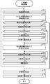
- FIG. 1 is a system configuration diagram illustrating a configuration example of an information processing system according to a first embodiment of the present invention. It is a hardware block diagram showing an example of 1 composition of a terminal unit. It is an external appearance block diagram showing an external appearance example of an automatic ticket gate. It is a hardware block diagram showing an example of 1 composition of a control device with which an automatic ticket gate is provided. It is an external appearance block diagram showing an example of an external appearance of a rocker device. It is a hardware block diagram showing an example of 1 composition of a control device with which a rocker device is provided. 5 is a diagram illustrating an example of a box management table stored in the locker device according to the first embodiment. FIG. It is a hardware block diagram showing one structural example of a delivery control server.
- FIG. 5 is a functional block diagram showing an example of functions of the delivery control server according to the first embodiment.
- FIG. 6 is a diagram illustrating an example of a user table stored in the delivery control server according to the first embodiment.
- FIG. 6 is a diagram illustrating an example of a usage state table stored in a delivery control server according to the first embodiment.
- FIG. It is a figure showing an example of the delivery scheduled luggage table which a delivery control server memorize
- 3 is a functional block diagram illustrating an example of functions of the mobile terminal according to the first embodiment.
- FIG. It is a flow chart showing movement information acquisition processing which a personal digital assistant performs.
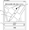
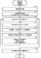
- FIG. 6 is a flowchart illustrating a receiving method information generation process executed by the delivery control server according to the first embodiment. It is a flowchart showing the receiving method approval process which a portable terminal performs. It is a figure showing an example of the receiving method adjustment screen which a portable terminal displays. It is a flow chart showing delivery control processing which a delivery control server performs.
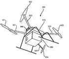
- 1 is an external configuration diagram illustrating an external appearance example of an unmanned aerial vehicle according to a first embodiment. It is a hardware block diagram showing the example of 1 structure of the control apparatus with which an unmanned aerial vehicle is equipped.
- FIG. 6 is an external configuration diagram illustrating an external appearance example of an unmanned aerial vehicle according to a second modification of the first embodiment. It is a figure showing an example of the landing port table which a delivery control server memorize
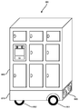
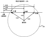
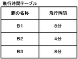
- stores. 13 is a flowchart showing a receiving method information generation process executed by the delivery control server according to the modified example 5 of the first embodiment. It is an external appearance block diagram showing an external appearance example of an unmanned ground vehicle. It is a figure showing an example of the station in a delivery area. It is a figure showing an example of the flight time table which a delivery control server memorizes.
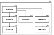
- FIG. 9 is a system configuration diagram illustrating a configuration example of an information processing system according to a second embodiment. 9 is a functional block diagram illustrating an example of functions of the mobile terminal according to the second embodiment.
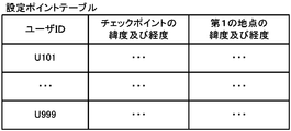
- FIG. It is a figure showing an example of the setting point table which a delivery control server memorize
- FIG. 9 is a functional block diagram illustrating an example of functions of a delivery control server according to a third embodiment.
- It is a flow chart showing movement detection processing which a delivery control server performs. 16 is a flowchart showing a receiving method information generation process executed by the delivery control server according to the second modification of the third embodiment. It is a figure showing an example of the use state table which the delivery control server which concerns on Example 4 memorize
- An information processing system 1 includes an information processing device 10 carried by a user and station affairs systems 21 and 22 for performing work at a station used by the user, as shown in FIG.
- the delivery system 30 delivers the parcel to the receiving place in the station designated by the information processing device 10.
- the information processing device 10, the station service systems 21 and 22, and the delivery system 30 are communicatively connected to the Internet IN.
- the information processing device 10 is, for example, a smartphone or a tablet-type personal computer, and has a size and weight suitable for carrying. Therefore, the information processing device 10 is hereinafter referred to as the mobile terminal 10.
- the mobile terminal 10 includes a CPU (Central Processing Unit) 101, a RAM (Random Access Memory) 102, a ROM (Read Only Memory) 103a, a flash memory 103b, a data communication circuit 104a, a voice communication circuit 104b, and a touch panel as shown in FIG. 105, a GPS (Global Positioning System) circuit 106, a speaker 107a, and a microphone 107b.
- CPU Central Processing Unit
- RAM Random Access Memory
- ROM Read Only Memory
- flash memory 103b a flash memory
- a data communication circuit 104a a voice communication circuit 104b
- a touch panel as shown in FIG. 105
- GPS Global Positioning System
- the CPU 101 controls the mobile terminal 10 as a whole by executing a program stored in the ROM 103a or the flash memory 103b.
- the RAM 102 temporarily stores data to be processed when the CPU 101 executes the program.
- the ROM 103a and the flash memory 103b store various programs.
- the flash memory 103b is a semiconductor memory and further stores various data and a table storing the data.
- the mobile terminal 10 may include a hard disk instead of the flash memory 103b.
- the data communication circuit 104a performs data communication using radio waves with a base station (not shown) connected to the Internet IN according to communication standards such as LTE (Long Term Evolution) and 3G (3rd Generation). As a result, the data communication circuit 104a performs data communication with the station service systems 21 and 22 and the delivery system 30 which are connected via the Internet IN.
- the voice communication circuit 104b performs voice communication using radio waves with a base station (not shown).
- the touch panel 105 includes a video card 105a, a display device 105b, and an input device 105c.
- the video card 105a renders an image based on the digital signal output from the CPU 101 and outputs an image signal representing the drawn image.
- the display device 105b is an LCD (Liquid Crystal Display) and displays an image according to the image signal output from the video card 105a.
- the mobile terminal 10 may include a PDP (Plasma Display Panel) or an EL (Electroluminescence) display instead of the LCD.
- the input device 105c is a touch pad and inputs a signal according to a user operation.
- the display device 105b and the input device 105c are arranged such that the display surface and the input surface overlap each other when viewed from the display direction of the display device 105b.
- the GPS circuit 106 receives a GPS signal emitted from a GPS satellite, measures the latitude and longitude of the mobile terminal 10 based on the received GPS signal, and outputs a signal representing the measured latitude and longitude.
- the speaker 107a inputs a signal representing the surrounding voice, and the microphone 107b outputs the voice according to the signal output by the CPU 101.
- a user carrying the mobile terminal 10 further carries an IC (Integrated Circuit) card 11 used to pay the fare with electronic money.
- the IC card 11 includes a communication circuit having an antenna (not shown), a CPU, a RAM, a ROM, and an EEPROM (Electrically Erasable Programmable Read-Only Memory).
- the communication circuit receives radio waves from the station service system 21 or 22 with an antenna, demodulates the signal output from the antenna, and outputs the demodulated signal to the CPU. In addition, the communication circuit modulates the signal output from the CPU, and transmits the modulated signal from the antenna to the station service system 21 or 22 as a radio wave.
- the configurations and functions of the CPU, RAM, and ROM of the IC card 11 are the same as the configurations and functions of the CPU 101, RAM 102, and ROM 103a of the mobile terminal 10 shown in FIG.
- the EEPROM of the IC card 11 is a rewritable memory, information is stored, updated, and deleted by the CPU, and the stored information is read by the CPU.
- the EEPROM stores identification information for identifying the IC card 11 (hereinafter referred to as a card ID (IDentification)) and information indicating a charge amount that is the amount of money deposited with a management body of electronic money.
- a card ID Identification
- Information indicating a charge amount that is the amount of money deposited with a management body of electronic money indicating a charge amount that is the amount of money deposited with a management body of electronic money.
- the communication circuit When the communication circuit receives from the station service system 21 or 22 a read signal instructing to read the information indicating the charge amount, the CPU reads the card ID and the information indicating the charge amount from the EEPROM according to the received read signal. read out. After that, the CPU outputs the read information to the communication circuit, and the communication circuit returns the output information to the station service system 21 or 22.
- the station duty system 21 or 22 communicates information indicating the amount of money (hereinafter referred to as the remaining amount) after deducting the entrance fee or the fare of the station from the amount of charge, and an update signal instructing to update the information indicating the amount of charge.
- the circuit receives.
- the CPU updates the information indicating the charge amount stored in the EEPROM with the information indicating the received remaining amount according to the received update signal. In this way, the entrance fee and fare to the station are settled by electronic money.
- the entrance fee and the fare are fixed regardless of the boarding/alighting station.
- a user carrying the IC card 11 performs an operation of causing the input device 105c of the mobile terminal 10 to download an application (hereinafter, simply referred to as a receipt method designation application) used for designating a receipt method of a package.
- an application hereinafter, simply referred to as a receipt method designation application
- the CPU 101 reads out a predetermined URL (Uniform Resource Locator) stored in advance in the flash memory 103b according to the signal.
- the CPU 101 generates a request for permitting the download of the receiving method designating application, and outputs the request to the data communication circuit 104a with the read URL as the destination.
- URL Uniform Resource Locator
- the CPU 101 executes the receiving method designating application.
- the CPU 101 requests the delivery system 30 to register the identification information for identifying the user (hereinafter referred to as the user ID) and the card ID of the IC card 11 used by the user, A registration request process (not shown) is executed. This is because the user prepares to specify the place in the station as the receiving place of the package addressed to the user by using the receiving method designation application.
- the CPU 101 causes the display device 105b to perform a display prompting the user to input the user ID and the card ID.
- the user who visually recognizes the display device 105b visually recognizes the card ID printed on the back surface of the IC card 11 and inputs the card ID of the IC card 11 and the user ID to the input device 105c.
- the CPU 101 When the input device 105c inputs a signal according to a user's operation, the CPU 101 generates a registration request for registering these pieces of information including a user ID and a card ID according to the input signal, and delivers the generated registration request.
- the data is output to the data communication circuit 104a with the system 30 as the destination. After that, the CPU 101 ends the execution of the registration request process after the data communication circuit 104a transmits the registration request.
- the user who has completed the preparation for using the delivery method designation app, carries the mobile terminal 10 and takes a train from station A, which is the closest station to his/her office, and gets off at station B, which is the station closest to the user's house.
- station A which is the closest station to his/her office
- station B which is the station closest to the user's house.
- station affairs system 21 is installed in the A station
- station affairs system 22 is described in the B station.
- the station affairs system 21 includes an automatic ticket gate 211 that permits or disallows entrance to the platform of the station A in response to payment of the entrance fee using the IC card 11, and a platform in response to payment of the fare. And an automatic ticket gate 212 that permits or departs from the exit.
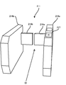
- the automatic ticket gate 211 includes a main machine 219a and a slave machine 219b as shown in FIG.
- the main machine 219a and the slave machine 219b are arranged so as to oppose each other across a passage leading to the platform, and each include a door 216a and a door 216b for opening and closing the passage.
- the main engine 219a communicates with the IC card 11 carried by the user at a position in front of the doors 216a and 216b toward the direction DI of entry to the home, and thereby an IC card reader/writer (Payment)
- the IC card RW217 includes a communication circuit (not shown) having the same configuration and function as the communication circuit included in the IC card 11.
- the main engine 219a opens the passage for a predetermined time when the payment of the entrance fee by the IC card RW217 succeeds, and closes the passage after the elapse of the predetermined time and when the payment fails.
- a control device 218 as shown in FIG. 4 for controlling opening/closing of the doors 216a and 216b is provided inside the housing.
- the control device 218 includes a CPU 281, a RAM 282, a ROM 283a, a flash memory 283b, a communication circuit 284, an input/output port 288, and a drive circuit 289.
- the configurations and functions of the CPU 281, RAM 282, ROM 283a, and flash memory 283b of the control device 218 are the same as the configurations and functions of the CPU 101, RAM 102, ROM 103a, and flash memory 103b of the mobile terminal 10 shown in FIG.
- the communication circuit 284 is, for example, a NIC (Network Interface Card), and communicates with the delivery system 30 via a router (not shown) connected to the Internet.
- the input/output port 288 is connected to the IC card RW217 of FIG. 3 via a communication cable (not shown), outputs the signal output by the CPU 281 to the IC card RW217, and inputs the signal output by the IC card RW217 to the CPU 281.
- the drive circuit 289 drives a motor (not shown) that opens and closes the doors 216a and 216b in FIG. 3 according to a signal output from the CPU 281.
- the antenna provided in the communication circuit shown in the figure is coupled by electromagnetic induction.
- the communication circuit of the IC card RW 217 detects the coupling of the antennas, it outputs a coupling signal reporting the coupling to the control device 218 of the automatic ticket gate 211.
- the CPU 281 of the control device 218 shown in FIG. 4 outputs a read signal to the IC card RW 217 via the input/output port 288 when the combined signal is input via the input/output port 288.
- the IC card RW 217 receives the card ID of the IC card 11 and the information indicating the charge amount after transmitting the output read signal to the IC card 11.
- the CPU 281 of the automatic ticket gate 211 acquires the card ID and the information indicating the charge amount input from the IC card RW 217, and determines whether the charge amount is equal to or more than the entrance fee read from the flash memory 283b at the time of startup. To determine. When the CPU 281 determines that the charge amount is equal to or more than the predetermined admission fee, the CPU 281 determines that the admission of the user using the IC card 11 is permitted.
- the CPU 281 After that, the CPU 281 generates an entrance notification including the card ID of the acquired IC card 11 and notifying that the user who used the IC card 11 has passed the automatic ticket gate 211 and entered the home. Next, the CPU 281 outputs the entrance notification to the communication circuit 284 with the delivery system 30 as the destination, and the communication circuit 284 transmits the output entrance notification.
- the CPU 281 calculates the remaining amount by subtracting the entrance fee from the charge amount, outputs the information indicating the remaining amount and the update signal to the IC card RW 217, and then outputs the signal instructing the opening of the passage to the drive circuit 289.
- the CPU 281 determines that the charge amount is less than the entrance fee, the CPU 281 refuses the entrance of the user who uses the IC card 11 and outputs a signal to the drive circuit 289 instructing to close the passage.
- the configuration and functions of the automatic ticket gate 212 shown in FIG. 1 are similar to those of the automatic ticket gate 211. However, while the automatic ticket gate 211 permits or disallows the user to enter the home according to the payment of the entrance fee and sends an admission notification when the admission is permitted, the automatic ticket gate 212 does not pay the fare. Accordingly, the difference is that the exit is permitted, and when the exit is permitted, the exit notification for notifying the user of leaving the home is transmitted.
- the station service system 22 installed at the B station includes automatic ticket gates 221 and 222 and locker devices 228 and 229.
- the configurations and functions of the automatic ticket gates 221 and 222 included in the station service system 22 of the B station are the same as the configurations and functions of the automatic ticket gates 211 and 212 included in the station service system 21 of the A station, respectively.
- the locker device 228 is provided with a plurality of storage boxes 810 as shown in FIG. 5, which are used for storing luggage. Also, the locker device 228 stores the luggage on the luggage racks 821 and 822 and the luggage on the luggage rack 821 or 822 in the storage box 810 where the luggage is not stored (that is, empty). And a robot arm 823 for controlling the robot arm. The locker device 228 further includes a control device 830 that controls locking and unlocking of the storage box 810 and operation of the robot arm 823.
- the storage box 810 is a door 811, a door frame 812 that receives the door 811, a dead bolt 813 that is a dogwood installed on the back surface of the door 811, and a seat for the dead bolt 813, and is installed in the door frame 812. And a strike 814.
- the storage box 810 locks the door 811 by inserting the dead bolt 813 into the strike 814 according to a signal output from the control device 830, and unlocks the door 811 by pulling out the dead bolt 813 from the strike 814.
- a motor (not shown) for locking is provided.
- the robot arm 823 is a vertical articulated robot, and includes a drive circuit that drives a motor (not shown) according to a signal output from the control device 830, and a two-claw gripper that is opened and closed in parallel by the motor.
- the robot arm 823 includes a photographing device 824 mounted on the gripper and having an optical axis directed toward the toe of the gripper, and a plurality of joint structures movable by a motor and a plurality of arms movable around the joint structure.
- Prepare The gripper is not limited to the two-claw type, and may have three or more claws, or may have a plurality of fingers instead of two claws.
- the image capturing device 824 included in the robot arm 823 is a digital stereo camera, performs image capturing according to a signal output from the control device 830, and outputs information representing two captured images having a parallax to each other to the control device 830. To do. This is because the control device 830 specifies the position coordinates, size, and the like of the gripping target object of the gripper in the three-dimensional space based on the parallax.
- the control device 830 includes a CPU 831, a RAM 832, a ROM 833a, a flash memory 833b, a data communication circuit 834a, a touch panel 835, an IC card RW 837, an input/output port 838, and a drive circuit 839 as shown in FIG.
- the configuration and functions of the CPU 831, the RAM 832, the ROM 833a, the flash memory 833b, the data communication circuit 834a, and the touch panel 835 of the control device 830 are the same as those of the CPU 101, the RAM 102, the ROM 103a, the flash memory 103b, and the data communication of the mobile terminal 10 illustrated in FIG.
- the configurations and functions of the circuit 104a and the touch panel 105 are the same.
- the configuration and function of the IC card RW837 of the control device 830 are the same as the configuration and function of the IC card RW217 included in the automatic ticket gate 211 shown in FIG.
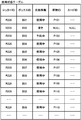
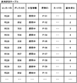
- the flash memory 833b stores a box management table as shown in FIG. 7, in which information used for managing the storage state of the storage box 810 is stored.
- the box management table uses a box ID for identifying the storage box 810, state information indicating the storage state of the storage box 810, a package ID of a package stored in the storage box 810, and a user who is the destination of the package.
- a plurality of pieces of data associated with the card ID of the IC card 11 to be stored are stored.
- the input/output port 838 is connected to a drive circuit (not shown) included in the robot arm 823 and a photographing device 824 via a communication cable (not shown).
- the input/output port 838 outputs the control signal output from the CPU 831 to the drive circuit of the robot arm 823 or the imaging device 824, and inputs the signal output from the imaging device 824 to the CPU 831.
- the drive circuit 839 is connected to a motor (not shown) included in each of the plurality of doors 811 via a plurality of cables (not shown), and drives each motor according to a signal output from the CPU 831.
- the locker device 228 Since the locker device 228 is installed at a position ahead of the automatic ticket gate 222 toward the exit direction (not shown) from the platform of the B station, not only passengers at the B station but also, for example, shoppers It may be used by such general users. Therefore, for example, a case where a shopper who is shopping around the B station deposits the increased luggage due to the shopping into the locker device 228 during the shopping will be briefly described first and the IC card 11 will be used. The receipt of the luggage by the user who gets on the train will be described in detail later.
- the touch panel 835 When the shopper stands in front of the locker device 228 and performs an operation to select an empty storage box 810 on the touch panel 835, the touch panel 835 outputs a signal according to the operation.
- the CPU 831 of the control device 830 shown in FIG. 6 acquires the identification information (hereinafter, referred to as a box ID) for identifying the storage box 810 selected by the shopper according to the signal output from the touch panel 835.
- the CPU 831 outputs the acquired box ID and an opening signal instructing unlocking and opening of the door 811 to the drive circuit 839.
- the drive circuit 839 drives a motor (not shown) included in the selected storage box 810 to unlock and open the door 811.
- the shopper designates the luggage stand 821 or 822 on which the luggage is placed and the operation to store the luggage placed on the luggage stand 821 or 822 in the robot arm 823.
- the CPU 831 acquires identification information (hereinafter, referred to as a luggage stand ID) for identifying the luggage stand 821 or 822 on which the luggage is placed based on the signal output from the touch panel 835.
- the CPU 831 is capable of photographing the luggage stand 821 or 822 after moving the imaging device 824 to a position where the obtained luggage stand ID and the luggage stand 821 or 822 identified by the luggage stand ID can be photographed.
- a control signal for directing the imaging device 824 to the direction is output to the input/output port 838 connected to the robot arm 823.
- the CPU 831 outputs a signal instructing shooting to the shooting device 824 via the input/output port 838, and the signal output from the shooting device 824 is input via the input/output port 838.
- the CPU 831 calculates the position coordinates and the size of the parcel to be stored in the three-dimensional space, based on the parallax between the two captured images represented by the input signal. After that, the CPU 831 acquires, from the flash memory 833b, information indicating the position coordinates and the size of the storage box 810 that is stored in advance in association with the box ID of the selected storage box 810.
- the CPU 831 grasps the package placed on the package platform 821 or 822 based on the information indicating the calculated position coordinate and size of the package and the acquired information indicating the position coordinate and size of the storage box 810. Generates a control signal to be stored in the storage box 810. After that, the CPU 831 outputs the generated control signal to the robot arm 823 through the input/output port 838, and the robot arm 823 operates according to the control signal to store the luggage in the storage box 810 selected by the shopper. The luggage of the shopper placed on the table 821 or 822 is stored.
- the CPU 831 controls the touch panel 835 so as to perform a display prompting to hold the IC card over the IC card RW837.
- the CPU 831 acquires a card ID for identifying the IC card of the shopper from the IC card RW837. This is because the acquired card ID is used as the electronic key of the door 811 of the selected storage box 810.
- the CPU 831 outputs to the drive circuit 839 a box ID of the selected storage box 810 and a closing signal instructing closing and locking of the door 811. After that, the CPU 831 uses the box management table of FIG.
- the luggage ID is set to “NULL” because the luggage ID is not given to the shopper's luggage. In this way, the baggage deposit is completed.
- the CPU 831 acquires the card ID from the IC card RW837, and the box ID associated with the acquired card ID. Is acquired from the box management table of FIG. This is to identify the storage box 810 that stores the shopper's luggage. After that, the CPU 831 outputs the acquired box ID and an opening signal for instructing the unlocking and opening of the door 811 to the drive circuit 839. Further, the CPU 831 updates the status information associated with the box ID in the box management table shown in FIG. 7 to the status information indicating the empty status, and updates the parcel ID and the card ID to “NULL”. Then, the shopper removes the package, and the package removal is completed.
- the CPU 831 of the locker device 228 executes a usage status notification process (not shown) that outputs a usage status notification that informs the delivery system 30 of the usage status of the locker at a predetermined cycle such as one minute.
- the delivery system 30 is for determining the receiving place of the package based on the usage state of the locker.
- the CPU 831 acquires from the flash memory 833b the information stored in the box management table of FIG. 7 and the identification information for identifying the locker device 228 (hereinafter referred to as the locker ID). ..
- the CPU 831 generates a usage status notification including the acquired information, and outputs the generated usage status notification to the data communication circuit 834a with the delivery system 30 as the destination. After that, when the data communication circuit 834a transmits the usage status notification, the CPU 831 ends the usage status notification process.
- the configuration and function of the locker device 229 are the same as the configuration and function of the locker device 228.
- the delivery system 30 is installed at a business office that delivers parcels in the area including the house of the user who uses the mobile terminal 10 and the station B.
- the delivery system 30 includes an information processing device 310 that processes information regarding delivery control of packages delivered to a business office, and an unmanned aerial vehicle 390 that delivers packages under the control of the information processing device 310. Since the information processing device 310 is a server machine, the information processing device 310 is hereinafter referred to as the delivery control server 310.
- the delivery control server 310 includes a CPU 311, a RAM 312, a ROM 313a, a hard disk 313b, a communication circuit 314, a video card 315a, a display device 315b, and an input device 315b as shown in FIG.
- the configurations and functions of the CPU 311, RAM 312, ROM 313a, video card 315a, and display device 315b of the delivery control server 310 are the same as those of the CPU 101, RAM 102, ROM 103a, video card 105a, and display device 105b of the terminal device 10 shown in FIG.
- the configuration and the function of the above are the same.
- the configuration and function of the communication circuit 314 of the delivery control server 310 are similar to the configuration and function of the communication circuit 284 included in the automatic ticket gate 211 shown in FIG.
- the hard disk 313b of the delivery control server 310 shown in FIG. 8 stores various data and a table storing the data.
- the delivery control server 310 may include a flash memory instead of the hard disk 313b.
- the input device 315c is, for example, one or more of a keyboard, a mouse, and a touch pad.
- the CPU 311 of the delivery control server 310 executes a user registration process (not shown) that registers the user ID of the user who uses the mobile terminal 10.
- the CPU 311 functions as the information acquisition unit 321 and the information storage unit 322 as illustrated in FIG. 9, and the hard disk 313b functions as the information storage unit 329.
- the information storage unit 329 stores a user table as shown in FIG. 10, in which one or more data in which the user ID of the user and the card ID of the IC card 11 used by the user are associated are stored. There is.
- the information acquisition unit 321 acquires the registration request from the communication circuit 314, and acquires the user ID and the card ID included in the registration request. Then, the information storage unit 322 associates the acquired user ID and card ID with each other, stores them in the user table of FIG. 10, and then ends the user registration process.
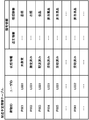
- the information storage unit 329 further stores a usage state table as shown in FIG. 11, in which information on the usage states of the locker devices 228 and 229 for which the storage fee is settled by the IC card is stored.
- a plurality of records are stored in the usage status table.
- the locker ID of the locker device 228 or 229, the box ID of the storage box 810 included in the locker device 228 or 229, the state information indicating the usage state of the storage box 810, and the storage box 810 are stored.
- Data in which the parcel ID of the parcel that has been stored and the card ID of the IC card 11 used by the user who is the destination of the parcel are associated are stored.
- the CPU 311 of the delivery control server 310 updates the usage status table of FIG. 11 based on the received usage status notification.
- a state update process (not shown) is executed.
- the information acquisition unit 321 acquires the usage status notification from the communication circuit 314, and the locker ID, box ID, status information, package ID, and card included in the usage status notification. Get the ID and.
- the information storage unit 322, in the usage status table of FIG. 11, acquires the status information, the baggage ID, and the card ID associated with the acquired locker ID and box ID, and the acquired status information and the baggage ID. After updating with the card ID, the execution of the status update processing ends.
- the information storage unit 329 further stores a planned delivery package table as shown in FIG. 12, in which a plurality of pieces of information regarding packages to be delivered (hereinafter referred to as planned delivery package information) are stored.
- the planned delivery baggage information includes information for identifying a package to be delivered (hereinafter referred to as a package ID), a user ID of a user designated as a destination of the package, and state information representing a delivery state of the package. It is the information in which the remark information indicating the remark such as the sender and the type of the parcel is associated.
- the undelivered state where the package receiving method is not specified the designated state where the package receiving method is specified but the package has not been delivered to the specified receiving location, the designated receiving location It includes a delivered state where the package has been delivered but the user has not received the package, and a received state where the package has been received by the user.
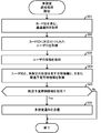
- the CPU 311 When the communication circuit 314 of the delivery control server 310 receives the admission notification notifying that the user has entered the home from the automatic ticket gate 211 shown in FIG. 1, the CPU 311 causes the package for the user whose receiving method is not specified. The unspecified notification process as shown in FIG. Accordingly, the CPU 311 detects the movement of the user from the A station where the automatic ticket gate 211 is installed, or the movement of the user who passes through the A station as a transit station, as a movement detection unit 323 as illustrated in FIG. 9. Function.
- the information acquisition unit 321 illustrated in FIG. 9 acquires the admission notification from the communication circuit 314 illustrated in FIG. 8 and acquires the card ID included in the admission notification (step). S01).
- the movement detection unit 323 acquires the user ID associated with the acquired card ID in the user table of FIG. 10 (step S02). This is for identifying the user who has used the IC card 11 identified by the card ID in the automatic ticket gate 211.
- the movement detection unit 323 detects movement of the user identified by the acquired user ID (step S03).
- the information acquisition unit 321 acquires the planned delivery package information including the acquired user ID and the status information indicating the unspecified state from the planned delivery package table of FIG. 12 (step S04).
- the information acquisition unit 321 determines whether or not the planned delivery package information has been acquired (step S05). At this time, when the information acquisition unit 321 determines that the planned delivery package information could not be acquired (step S05; No), there is a package addressed to the user who has detected the movement, and a package for which the receiving method is not specified exists. Determine not to. Then, the information acquisition unit 321 ends the execution of the unspecified notification process without transmitting the unspecified notification.
- the information acquisition unit 321 determines that the planned delivery package information has been acquired (step S05; Yes)
- the information acquisition unit 321 includes the planned delivery package information and notifies that the receiving method is not specified for the package. Generate an unspecified notification. After that, the information acquisition unit 321 outputs the generated unspecified notification to the communication circuit 314 addressed to the mobile terminal 10 used by the user who has detected the movement (step S06), and the communication circuit 314 transmits the unspecified notification. Then, the execution of the unspecified notification process ends.
- the mobile terminal 10 After the user passes through the automatic ticket gate 211 of the A station, when the delivery control server 310 that receives the admission notification from the automatic ticket gate 211 transmits the unspecified notification, the mobile terminal 10 carried by the user receives the unspecified notification. To do. Therefore, the mobile terminal 10 usually receives the unspecified notification while the user waits for the train at the platform of the A station or while traveling on the train from the A station to the B station.
- the CPU 101 of the mobile terminal 10 executes an execution prompting process (not shown) that prompts the execution of the receiving method designation application.
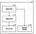
- the CPU 101 functions as a voice display control unit 125 that controls the information acquisition unit 121 and the display and voice output that prompts execution of the receiving method designation application as shown in FIG.
- the information acquisition unit 121 acquires the unspecified notification from the data communication circuit 104a and acquires the planned delivery package information included in the acquired unspecified notification. Then, the information acquisition unit 121 acquires the remark information included in the planned delivery package information, and the voice display control unit 125 prompts the user to specify the method of receiving the package and the sender of the package represented by the remark information. And the type, the touch panel 105 is controlled to display. Next, the voice display control unit 125 controls the speaker 107a so as to output a voice prompting the designation of the receiving method, and then ends the execution prompting process.
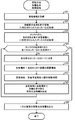
- the CPU 101 When the user who visually recognizes the message and the sender and type of the package performs an operation to activate the receiving method designating application on the touch panel 105, the CPU 101 causes the CPU 101 to designate the receiving method according to a signal output in response to the operation. Run the app. As a result, the CPU 101 executes a movement information acquisition process as shown in FIG. 15, which acquires information (hereinafter referred to as movement information) regarding the movement of the user used for generating the receiving method.
- movement information information regarding the movement of the user used for generating the receiving method.
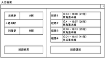
- the voice display control unit 125 of the mobile terminal 10 shown in FIG. 14 shows the input screen used for inputting the movement information as shown in FIG. 16 as shown in FIG. It is displayed on the display device 105b (step S11).
- the movement information is information indicating a station where the user gets off the train or an arrival station which is a station where the user finally gets on the train (hereinafter referred to as a first point).
- the description will be made assuming that the information includes the estimated time of arrival of the train at the first point. Since the point where the user arrives by train is the B station, the following description will be made assuming that the information indicating the name of the B station is the information indicating the first point.
- step S11 the information acquisition unit 121 acquires signals representing latitude and longitude from the GPS circuit 106 shown in FIG. 2 (step S12).
- the information acquisition unit 121 includes a request for searching the nearest station from the point represented by the latitude and longitude, including the information indicating the latitude and longitude, and a request (not shown) connected to the Internet IN.
- the data is output to the data communication circuit 104a with the engine as the destination.
- the search engine has a station search table (not shown) in which the information indicating the name of the station and the information indicating the latitude and longitude of the station are stored in association with each other in advance. Therefore, the search engine, among the information indicating the latitude and longitude stored in the station search table, information indicating the latitude and longitude of the point having the shortest distance from the point in the latitude and longitude represented by the request. Specify. Next, the search engine searches the search table for information indicating the name of the station A associated with the information indicating the latitude and longitude specified in the station search table.
- the information acquisition unit 121 acquires the response from the data communication circuit 104a.
- the information acquisition unit 121 sets the information indicating the name of the station A included in the response as the information indicating the name of the departure station (step S13).
- the voice display control unit 125 controls the display device 105b to display the searched station A as the departure station name on the input screen of FIG.
- the information acquisition unit 121 causes the information acquisition unit 121 to input the name of the station B, which is the arrival station, based on the signal output by the input device 105c according to the operation. Is obtained (step S14).
- the information acquisition unit 121 includes information indicating the name of the departure station and information indicating the name of the arrival station, and a movement route that can be used when moving from the departure station to the arrival station by train, and arrival. Generate a request to search for a combination of the estimated time of arrival at the station. After that, the information acquisition unit 121 outputs the generated request to the data communication circuit 104a with the search engine as the destination.
- the search engine is information indicating a railway line, information indicating a name of a station on the railway line, information indicating a scheduled arrival time of a train at the station, and information indicating a scheduled departure time from the station, Stores a route search table (not shown) that is stored in association with each other in advance.
- the search engine uses the route search table, the information indicating the name of the departure station and the information indicating the name of the arrival station included in the request, and the current time managed by, for example, the OS (Operating System), to determine the movement route. And one or a plurality of combinations of the scheduled arrival time and the expected arrival time are searched.
- the information acquisition unit 121 acquires the received one or more combinations from the data communication circuit 104a (step S15).
- the voice display control unit 125 controls the display device 105b so as to display a plurality of the received one or a plurality of combinations on the input screen of FIG. 16 (step S16).
- the user who visually recognizes the display device 105b performs an operation of selecting a combination of the moving route of the train to be boarded or the train already boarded and the estimated arrival time from the one or a plurality of combinations displayed on the input screen. To do.
- the input device 105c outputs a signal in response to the operation, the information acquisition unit 121 identifies the selected combination based on the signal (step S17).
- the information acquisition unit 121 includes, from the information indicating the specified combination, information indicating the name of the arrival station B, which is the final point of the travel route (that is, information indicating the first point), and the specified combination.
- the information indicating the estimated arrival time at the arrival station B (that is, the first point) and the movement information are acquired (step S18).
- the information acquisition unit 121 outputs the acquired movement information to the data communication circuit 104a with the delivery control server 310 as the destination (step S19), and after the data communication circuit 104a transmits the movement information, the movement information acquisition processing is performed. Finish execution.
- the information storage unit 329 of the delivery control server 310 shown in FIG. 9 stores an installation location table as shown in FIG. 17, in which information about the installation locations of the locker devices 228 and 229 is stored. Has multiple records stored. In each record of the installation location table, the locker IDs of the locker devices 228 and 229, information indicating the name of the station where the locker devices 228 and 229 are installed, and the latitude and longitude of the installation locations of the locker devices 228 and 229 are represented. Data in which information is associated with information indicating the average travel time required to travel from the platform of the station to the locker device 228 or 229 (hereinafter, referred to as in-station travel time) is stored.
- the CPU 311 When the communication circuit 314 of the delivery control server 310 shown in FIG. 8 receives the movement information, the CPU 311 generates information indicating a package receiving method (hereinafter referred to as receiving method information), and the receiving method as shown in FIG. Executes information generation processing. Thereby, the CPU 311 further functions as an information generation unit 324 as shown in FIG. 9, which generates the reception method information.
- the information acquisition unit 321 illustrated in FIG. 9 acquires movement information from the communication circuit 314 (step S21), and information indicating the name of the arrival station included in the movement information. And information indicating the estimated arrival time at the arrival station.
- the information acquisition unit 321 acquires a locker ID associated with the acquired information indicating the name of the arrival station B station from the installation location table of FIG. 17 (step S22). This is for identifying the locker devices 228 and 229 installed at the B station.
- the information acquisition unit 321 acquires a box ID associated with the acquired locker ID and the status information indicating the vacant status from the usage status table of FIG. 11 (step S23). After that, the information acquisition unit 321 determines whether or not attention has been paid to all the locker IDs for which the box IDs have been acquired (step S24). This is to determine whether or not there is a storage box 810 in an empty state.
- the information generation unit 324 sets it as one of the unfocused locker IDs.
- the locker device 228 or 229 identified by the focused locker ID is set as the focused locker device 228 or 229 (step S25).
- the information acquisition unit 321 acquires information indicating the latitude and longitude associated with the locker ID of the noted locker device 228 or 229 and information indicating the in-station travel time from the installation location table of FIG. ..
- the information generation unit 324 acquires, for example, the planned delivery package information acquired in step S04 of FIG. 13, which is stored in the shared memory. This is because the planned delivery package information acquired in step S04 is information acquired by a process different from the receiving method information generation process which is the process being executed.
- the information generation unit 324 sets the installation location of the locker device 228 or 229 of interest located at the latitude and longitude represented by the acquired information as the receiving location of the package related to the acquired planned delivery package information (step S26). ).
- the information generation unit 324 sets the time obtained by adding the intra-station travel time represented by the acquired information to the scheduled arrival time represented by the information acquired in step S21 as the receipt time of the package ( Step S27).
- the receiving place and the receiving time determined by the information generating unit 324 are provisional, and are approved after adjustment is made as necessary in the process described later.
- the information generation unit 324 includes a combination of information indicating the latitude and longitude of the determined receiving place and information indicating the determined receiving time, and receives the package at the receiving time at the receiving place. After generating the receiving method information indicating (step S28), the above steps are repeated from step S24.
- step S24 When it is determined in step S24 that the information acquisition unit 321 has focused on all the locker IDs for which the box IDs could be acquired in step S23 (step S24; Yes), the information generation unit 324 generates the 1 or 1 generated in step S28.
- the plurality of pieces of receiving method information are output to the communication circuit 314 shown in FIG. 8 in the order of generation, with the mobile terminal 10 as the destination (step S29).
- the information generating unit 324 ends the execution of the receiving method information generating process.
- the CPU 101 of the mobile terminal 10 causes the CPU 101 of the one or more receiving method information to represent one or a plurality of receiving methods, respectively.
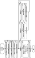
- One of the receiving methods is selected from among the above, and the receiving method approval processing as shown in FIG. 19 is executed, which is adjusted as necessary and approved.
- the CPU 101 further functions as the information generation unit 124 and the instruction output unit 126 as shown in FIG. In the present embodiment, for ease of explanation, the case where the mobile terminal 10 receives two pieces of receiving method information will be described as an example.
- the information acquisition unit 121 acquires two pieces of receiving method information from the data communication circuit 104a in the order of transmission (step S31). Next, the information acquisition unit 121 controls the display device 105b to display the receiving method adjustment screen as shown in FIG. 20, which is used for adjusting the receiving method (step S32).
- the information acquisition unit 121 acquires the information indicating the latitude and longitude of the receiving place from each of the two receiving method information, and includes the information indicating the latitude and longitude of the acquired two receiving places, and the two receiving places. Generate a request to return information representing the map displaying. Next, the information acquisition unit 121 outputs the generated request to the data communication circuit 104a in FIG. 2 with the search engine (not shown) as the destination.
- the search engine stores a map table (not shown) in which information indicating a map, information indicating the minimum latitude and the minimum longitude of points included in the map, and information indicating the maximum latitude and the maximum longitude are stored. ..
- the search engine has information indicating a minimum latitude and a minimum longitude that are smaller than all of the two latitudes and longitudes represented by the information included in the request, and a maximum latitude that is greater than all of the two latitudes and longitudes.
- Information indicating the map associated with the information indicating the maximum longitude is acquired from the map table. Then, the search engine returns a response including the information indicating the acquired map, the information indicating the minimum latitude and the minimum longitude associated with the information indicating the map, and the information indicating the maximum latitude and the maximum longitude. ..
- the information acquisition unit 121 acquires the response from the data communication circuit 104a. After that, the information acquisition unit 121, based on the information indicating the latitude and longitude of the two receiving locations, the information indicating the minimum latitude and the minimum longitude included in the response, and the information indicating the maximum latitude and the maximum longitude, The drawing positions of the two receiving locations on the map represented by the information included in the response are specified. After that, the information generation unit 124 synthesizes the two receiving place icons R1 and R2, which respectively represent the two receiving places, with the drawing positions of the two specified receiving places, and the map display area as shown in FIG. The display device 105b is controlled to display the combined map on the MA (step S33).
- the display states of the receiving place icons R1 and R2 are a state in which the receiving place indicated by the receiving place icons R1 and R2 is selected by the user (hereinafter, referred to as a selected state), and a state in which the receiving place icons are not selected. And a state indicating that (hereinafter, referred to as a non-selected state).
- the receiving place icons R1 and R2 in the selected state are icons in which the receiving place icons R1 and R2 in the non-selected state are highlighted.
- the reverse display may be color reverse display including black and white reverse display and color reverse display, or may be dark display or bright display.
- the display state of the receiving place icon R1 shown in FIG. 20 is a selected state, and the display state of the receiving place icon R2 is a non-selected state. Therefore, the receiving place icon R1 shown in FIG. 20 is an icon in which the receiving place icon R2 is highlighted.
- step S33 the information generation unit 124 considers that the receiving place represented by the receiving method information received first is selected by the user, and changes the display state of the receiving place icon R1 to the selected state.
- the display device 105b is controlled to switch. Further, the information generating unit 124 considers that the receiving place represented by the receiving method information received second is not selected by the user, and switches the display state of the receiving place icon R2 to the non-selected state. 105b is controlled (step S34).
- the information generating unit 124 controls the display device 105b to display the reception time represented by the reception method information received first in the reception time display area TA as shown in FIG. 20 (step S35). ). In this way, the receiving method represented by the receiving method information received first is presented to the user.
- the input device 105c performs the operation.
- the corresponding signal is output.
- the information generation unit 124 determines that the operation is It is determined that the operation is a selection operation (step S37; Yes).
- the information generating unit 124 sets the receiving place represented by the receiving place icon R2 as the receiving place selected by the user based on the signal output from the input device 105c.
- the information generator 124 switches the display state of the receiving place icon R1 to the non-selected state, and then switches the display state of the receiving place icon R2 to the selected state (step S38).
- the information generation unit 124 controls the display device 105b to display the reception time represented by the information combined with the information indicating the latitude and longitude of the selected reception place in the reception time display area TA ( Step S39), the process returns to step S36 and the above steps are repeated.
- the information generation unit 124 determines that the operation is not the approval operation and the selection operation based on the signal output by the input device 105c according to the operation (step S36; No and step S37; No), and It is determined that the operation is an adjusting operation (step S40; Yes).
- the information generator 124 adjusts the receiving time being displayed based on the signal output from the input device 105c (step S41), and displays the adjusted receiving time in the receiving time display area TA. After controlling (step S42). Returning to step S36, the above steps are repeated.
- the information generation unit 124 determines that the operation is an approval operation based on the signal output from the input device 105c (step S36; Yes). After that, the information generating unit 124 determines that the receiving method for receiving the package has been approved at the selected receiving location at the displayed receiving time. Next, the information generating unit 124 newly generates the receiving method information indicating the approved receiving method including the combination of the information indicating the receiving time and the information indicating the latitude and longitude of the receiving place (step S43). ).
- the instruction output unit 126 uses the newly generated receiving method information as a delivery instruction that specifies the delivery destination (that is, the receiving location) of the package and the delivery time (that is, the receiving time). After that, the instruction output unit 126 outputs the delivery instruction to the data communication circuit 104a of FIG. 2 with the delivery control server 310 as the destination (step S44), and the data communication circuit 104a transmits the delivery instruction, and then the receiving method. The execution of the approval process ends.
- the CPU 311 of the delivery control server 310 controls delivery of the package by the unmanned aerial vehicle 390 shown in FIG. 1, based on the delivery instruction.
- the delivery control process as shown in FIG. 21 is executed.
- the CPU 101 reserves the locker device 228 or 229 for storing the parcel delivered by the unmanned aerial vehicle 390, and the reservation unit 325 as shown in FIG. 9, and an instruction to output the parcel delivery instruction to the unmanned aerial vehicle 390. It further functions as the output unit 326.
- the information acquisition unit 321 acquires the delivery instruction transmitted from the mobile terminal 10 from the communication circuit 314 (step S51), and includes it in the planned delivery package information obtained in step S04 of FIG. Acquire the package ID to be stored.
- the information storage unit 322 updates the status information associated with the acquired package ID and the planned shipping package table of FIG. 12 to the status information indicating the designated status (step S52). This is because the delivery instruction acquired in step S51 specifies the method of receiving the package identified by the package ID.
- the reservation unit 325 in FIG. 9 acquires the locker ID associated with the information indicating the latitude and longitude of the receiving place included in the delivery instruction from the installation place table in FIG. 17, and acquires the locker ID and the available space.
- the box ID associated with the status information of the status is acquired from the usage status table of FIG. This is for identifying the locker device 228 installed at the approved receiving place and the storage box 810 in an empty state included in the locker device 228.
- the reservation unit 325 acquires the user ID associated with the package ID from the planned delivery package table of FIG. 12, and acquires the card ID associated with the acquired user ID from the user table of FIG. .. This is because the user who is the destination of the parcel specifies the IC card 11 used for receiving the parcel.
- the reservation unit 325 makes a reservation request including the acquired box ID, baggage ID, and card ID for requesting the reservation of the storage box 810 with the locker device 228 identified by the acquired locker ID as the destination.
- the data is output to the communication circuit 314 (step S53).
- the CPU 831 of the locker device 228 shown in FIG. 6 When the data communication circuit 834a receives the reservation request, the CPU 831 of the locker device 228 shown in FIG. 6 outputs the box ID and the closing signal included in the reservation request to the drive circuit 839, thereby identifying the box ID.
- the door 811 included in the storage box 810 is closed and locked.
- the CPU 831 associates the box ID of the closed storage box 810, the state information indicating the reserved state, the package ID and the card ID included in the reservation request, and stores them in the box management table in FIG. 7. .. In this way, the reservation of the storage box 810 for storing the luggage is completed.
- the information acquisition unit 321 acquires previously stored information indicating the latitude and longitude of the business office from the hard disk 313b shown in FIG. After that, the information acquisition unit 321 includes information indicating the latitude and longitude of the business office and information indicating the latitude and longitude of the receiving place included in the delivery instruction, and realizes the minimum flight distance from the business office to the receiving place. Generate a request to search for a flight path. After that, the information acquisition unit 321 outputs the request to the communication circuit 314 illustrated in FIG. 8 with the search engine (not illustrated) as the destination.
- the search engine represents information indicating edges corresponding to partial routes in which the unmanned aerial vehicle 390 can fly, such as roads and rivers around the B station, nodes indicating respective start points and end points of the partial routes, and distances of the partial routes.
- Information and a route table in which the information is stored are stored.
- the search engine uses a route table to execute a route search algorithm such as the Dijkstra method, and achieves the shortest flight distance among multiple flight routes that combine partial routes from the sales office to the receiving location. Search for a route. After that, the search engine returns a response including information indicating the latitude and longitude of the node forming the shortest flight route (hereinafter, simply referred to as information indicating the shortest flight route) and information indicating the shortest flight distance.
- the information acquisition unit 321 acquires the information indicating the shortest flight distance included in the received response, and the previously stored unmanned aircraft. Information representing the average flight speed of 390 is acquired from the hard disk 313b shown in FIG.
- the instruction output unit 326 determines the delivery time by dividing the shortest flight distance represented by the acquired information by the average flight speed of the unmanned aerial vehicle 390, and determines the delivery time that is earlier than the receiving time by the delivery time. Determine the delivery start time.
- the information acquisition unit 321 acquires information indicating the shortest flight route included in the received response, and the instruction output unit 326 determines the shortest flight route represented by the acquired information as the delivery route (step). S54).
- the instruction output unit 326 includes the acquired package ID, information indicating the delivery route of the package identified by the package ID, and information indicating the delivery start time, and leaves the business office at the delivery start time. Then, by flying the delivery route, a new delivery instruction for instructing to deliver the package to the receiving place by the receiving time is generated (step S55). Next, the instruction output unit 326 outputs the generated delivery instruction as a control instruction for the unmanned aerial vehicle 390, and outputs the unmanned aerial vehicle 390 as a destination to the communication circuit 314 (step S56).
- the instruction output unit 326 includes a message including the package ID and the remarks information included in the planned delivery package information acquired in step S04 of FIG. 13, and prompting to load the package identified by the package ID into the unmanned aerial vehicle 390.
- the unmanned aerial vehicle 390 includes a controller 910 for controlling the attitude and flight of the unmanned aerial vehicle 390, and propeller arms protruding from the controller 910 to the front right, the front left, the rear left, and the rear right, respectively. 921 to 924, propellers 931 to 934 installed at the tips of the propeller arms 921 to 924, and a motor (not shown) that rotates the propellers 931 to 934 under the control of the control device 910.
- the unmanned aerial vehicle 390 includes a first surrounding frame 941a surrounding four sides of one of the four side surfaces of a rectangular parallelepiped-shaped luggage, and a surface surrounded by the first surrounding frame 941a (hereinafter, A second enclosing frame 941b enclosing four sides of a side surface (hereinafter referred to as a second enclosing surface) that faces the first enclosing surface) is provided below the control device 910.
- the unmanned aerial vehicle 390 is extended in the normal direction of the first enclosing surface and the second enclosing surface of the luggage, suspends the first enclosing frame 941a and the second enclosing frame 941b, and
- the lower surface of the control device 910 is provided with guide rails 942a and 942b extending in the moving direction of the first surrounding frame 941a and the second surrounding frame 941b.
- the unmanned aerial vehicle 390 moves the first enclosing frame 941a and the second enclosing frame 941b toward each other under the control of the control device 910, so that the first enclosing frame 941a and the second enclosing frame 941a.
- the unmanned aerial vehicle 390 is provided on the upper surface of the control device 910, and includes an image capturing device 951 whose optical axis is directed in front of the unmanned aerial vehicle 390. Still further, if the unmanned aerial vehicle 390 is provided on the lower surface of the control device 910, the optical axis is directed below the unmanned aerial vehicle 390, and the luggage is placed below the unmanned aerial vehicle 390, the luggage and the first enclosure frame An imaging device 952 having an angle of view including the 941a and the second surrounding frame 941b in the imaging range is provided.
- the configurations and functions of the image capturing devices 951 and 952 are similar to the configurations and functions of the image capturing device 824 included in the locker device 228 shown in FIG.
- the control device 910 includes a CPU 911, a RAM 912, a ROM 913a, a flash memory 913b, a data communication circuit 914a, a touch panel 915, a GPS circuit 916, an input/output port 918, and a drive circuit 919 as shown in FIG.
- the CPU 911, the RAM 912, the ROM 913a, the flash memory 913b, the data communication circuit 914a, the touch panel 915, and the GPS circuit 916 of the control device 910 have the same configurations and functions as the CPU 101, the RAM 102, the ROM 103a, and the flash memory of the mobile device 10 illustrated in FIG.
- the configurations and functions of 103b, the data communication circuit 104a, the touch panel 105, and the GPS circuit 106 are the same.
- the input/output port 918 is connected to a communication cable (not shown) connected to each of the image capturing devices 951 and 952, outputs a signal output from the CPU 911 to the image capturing device 951 or 952, and outputs the signal to the image capturing device 951 or 952.
- the signal is input to the CPU 911.
- the drive circuit 919 moves four cables (not shown) respectively connected to motors (not shown) that rotate the propellers 931 to 934 shown in FIG. 22, and the first surrounding frame 941a and the second surrounding frame 941b. And a cable connected to a motor (not shown).
- the drive circuit 919 drives a motor (not shown) that rotates the propellers 931 to 934 or a motor (not shown) that moves the first surrounding frame 941a and the second surrounding frame 941b according to a signal output from the CPU 911. ..
- the worker working at the sales office visually recognizes the message displayed on the display device 315b of the delivery control server 310, he or she searches for the package identified by the package ID according to the message. Next, the worker places the found luggage on a workbench (not shown) installed near the unmanned aerial vehicle 390, and performs an operation to start delivery of the luggage on the touch panel 915 of the unmanned aerial vehicle 390.
- a workbench not shown
- the CPU 911 of the control device 910 included in the unmanned aerial vehicle 390 executes flight control processing as shown in FIG. 24 for controlling flight of the unmanned aerial vehicle 390.
- the CPU 911 When the CPU 911 starts executing the flight control process, it outputs a control signal for raising the unmanned aerial vehicle 390 to a predetermined altitude to the drive circuit 919, and the drive circuit 919 follows the propellers 931 to 934 shown in FIG. 22 according to the control signal.
- a motor (not shown) for rotating the motor is driven.
- the CPU 911 outputs a signal instructing shooting to the shooting device 952 provided below the unmanned aerial vehicle 390 via the input/output port 918.
- the CPU 911 analyzes the photographed image to photograph the luggage area in which the luggage looked down from above is drawn. Detect from image.
- CPU 911 outputs to control circuit 919 a control signal for moving unmanned aerial vehicle 390 directly above the luggage based on the detected luggage area.
- the CPU 911 outputs to the drive circuit 919 a control signal for sufficiently separating the first surrounding frame 941a and the second surrounding frame 941b shown in FIG. 22, and the driving circuit 919 follows the control signal to output the first surrounding frame 941a.
- a motor (not shown) that moves the holding frame 941a and the second surrounding frame 941b is driven.
- the CPU 911 outputs the signal for instructing the image capturing to the image capturing device 952 again, and analyzes the captured image again, thereby drawing the luggage area and the first surrounding frame 941a and the second surrounding frame 941b, respectively.
- the first frame area and the second frame area are detected.
- the CPU 911 lands the unmanned aerial vehicle 390 while straddling the luggage with the first holding frame 941a and the second holding frame 941b based on the luggage area and the first frame area and the second frame area.
- a control signal for sufficiently lowering the altitude of the unmanned aerial vehicle 390 is output to the drive circuit 919.
- the CPU 911 outputs a control signal to the drive circuit 919 to bring the first enclosing frame 941a and the second enclosing frame 941b sufficiently close to each other, so that the unmanned aerial vehicle 390 causes the first enclosing frame 941a and the second enclosing frame 941a.
- the luggage is enclosed with the enclosure frame 941b, and the loading of the luggage by the unmanned aerial vehicle 390 is completed (step S61).
- the CPU 911 acquires the control instruction received by the data communication circuit 914a from the delivery control server 310 (step S62), and acquires the information indicating the delivery start time included in the control instruction and the information indicating the delivery route. To do.
- the CPU 911 acquires the system time managed by the OS, for example, and determines whether the delivery start time has arrived, based on whether the acquired system time is later than the delivery start time. Yes (step S63). At this time, when the CPU 911 determines that the delivery start time has not arrived because the system time is earlier than the delivery start time (step S63; No), the CPU 911 sleeps for a predetermined time and then repeats step S63.
- step S63 when the CPU 911 determines that the delivery start time has arrived because the system time is the same as the delivery start time or is later than the delivery start time (step S63; Yes), the delivery route is advanced. 23, the control signal for controlling the propellers 931 to 934 shown in FIG. 22 is output to the drive circuit 919 shown in FIG. 23 (step S64).
- step S64 the CPU 911 acquires a signal from the GPS circuit 916 and acquires information indicating the latitude and longitude of a plurality of nodes included in the delivery route from the information indicating the delivery route. After that, the CPU 911 determines the difference between the latitude and longitude of the unmanned aerial vehicle 390 represented by the acquired signal and the latitude and longitude of the closest node among the plurality of unpassed nodes represented by the acquired information. It generates and outputs a control signal that causes the flight to be reduced. Further, in step S64, CPU 911 outputs a signal for instructing shooting via input/output port 918 to shooting device 951 whose optical axis is oriented in front of unmanned aerial vehicle 390. After that, the CPU 911 generates and outputs a control signal for flying to avoid an obstacle based on the information representing the captured image input from the image capturing device 951 via the input/output port 918.
- the CPU 911 determines the latitude of the node indicating the end point of the delivery route (that is, the receiving place) based on the signal output from the GPS circuit 916 and the information indicating the latitude and longitude of the node included in the delivery route. The difference between the longitude and the latitude and longitude of the unmanned aerial vehicle 390 is calculated. Next, the CPU 911 determines that the difference between the latitude and longitude of the node representing the receiving place and the latitude and the longitude of the unmanned aerial vehicle 390 is less than or equal to a predetermined value. Whether or not the unmanned aerial vehicle 390 has arrived at the receiving place is determined based on whether or not (step S65).
- Arrival of the unmanned aerial vehicle 390 at the receiving location does not necessarily mean that the unmanned aerial vehicle 390 is landing at the receiving location or within a predetermined distance from the receiving location.
- the unmanned aerial vehicle 390 arrives at the receiving place, it means, for example, that the aircraft is hovering in the air without landing at or near the receiving place, that it is landing and then taking off and hovering, and receiving It also means turning or reciprocating over or near the place.
- step S65 determines in step S65 that the unmanned aerial vehicle 390 has not arrived at the receiving place because the difference is larger than the predetermined value (step S65; No), the above steps from step 64 are repeated.
- the CPU 911 determines that the unmanned aerial vehicle 390 has arrived at the receiving place because the difference is less than or equal to the predetermined value (step S65; Yes)
- it includes the package ID included in the control instruction, and the package ID
- An arrival notice notifying that the identified package has arrived at the receiving place is output to the data communication circuit 914a with the delivery control server 310 as the destination (step S66).
- the data communication circuit 914a wirelessly transmits an arrival notification to a base station (not shown) connected to the Internet IN.
- the unmanned aerial vehicle 390 moves directly above the luggage carrier 821 or 822 included in the locker device 228 shown in FIG. 5 and then lands on the luggage carrier 821 or 822, or changes the altitude of the unmanned aerial vehicle 390. Lower enough. After that, the unmanned aerial vehicle 390 places the luggage on the luggage rack 821 or 822 by releasing the luggage from the first surrounding frame 941a and the second surrounding frame 941b (step S67).
- the CPU 911 of the unmanned aerial vehicle 390 outputs a control signal for controlling the propellers 931 to 934 to the drive circuit 919 so as to fly backward to the sales route to the business office (step S68), and then the flight control process is executed. To finish.
- the CPU 311 changes the package ID included in the arrival notification and the status information indicating the reservation status from the usage status table shown in FIG. The associated locker ID is acquired.
- the CPU 311 of the delivery control server 310 transfers the arrival notification by outputting the arrival notification to the communication circuit 314 with the locker device 228 identified by the acquired locker ID as the destination.
- the CPU 831 of the locker device 228 When the data communication circuit 834a of the locker device 228 shown in FIG. 6 receives the arrival notification from the delivery control server 310, the CPU 831 of the locker device 228 responds to the package ID and the status information indicating the reserved status included in the arrival notification. The attached box ID is acquired, and the acquired box ID and release signal are output to the drive circuit 839. As a result, the door 811 of the storage box 810 currently reserved is unlocked and opened.
- the locker device 228 grabs the luggage placed on the luggage stand 821 or 822 with the robot arm 823 and stores it in the empty storage box 810, similarly to the case where the shopper's luggage is stored.
- the door 811 of 810 is closed and locked.
- the CPU 831 of the locker device 228 illustrated in FIG. 6 is associated with the box ID of the storage box 810 in which the package is stored and the package ID included in the arrival notification in the box management table of FIG. 7.
- the information is updated to the status information indicating the busy status.
- the CPU 831 of the locker device 228 outputs a storage completion notification including the package ID and notifying that the storage is completed to the data communication circuit 834a with the delivery control server 310 as the destination.
- the delivery control server 310 CPU 311 displays the status information associated with the package ID included in the storage completion notification in the scheduled delivery package table of FIG. Update to the status information that represents the status.
- the user When the user arrives at the receiving place after the luggage is stored in the locker device 228 at the receiving place, the user holds the IC card 11 over the IC card RW837 of the locker device 228 shown in FIG.
- the CPU 831 of the locker device 228 illustrated in FIG. 6 causes the box ID associated with the input card ID, the baggage ID, Is acquired from the box management table of FIG. After that, the CPU 831 outputs the acquired box ID and an opening signal for instructing the unlocking and opening of the door 811 to the drive circuit 839.
- the CPU 831 of the locker device 228 updates the package ID and the card ID associated with the acquired box ID to “NULL”, and the status information associated with the box ID becomes status information indicating an empty status. Update. After that, when the user takes out the package from the storage box 810, the receipt of the package is completed.
- the CPU 831 of the locker device 228 outputs a receipt notification including the package ID and notifying that the package has been received, to the data communication circuit 834a with the delivery control server 310 as the destination.
- the delivery control server 310 displays the status information associated with the package ID included in the receipt notification in the scheduled delivery package table of FIG. Update to the status information.
- the mobile terminal 10 and the delivery control server 310 generate the receiving method information indicating the receiving method for the user to receive the package based on the movement information regarding the movement of the user. Therefore, regardless of the movement of the user, the package can be delivered by a delivery method sufficiently convenient for the user, for example, as compared with the case of delivering the package to the user's house or the like.
- the mobile terminal 10 and the delivery control server 310 generate the receiving method information based on the movement information from the time when the movement information is acquired until the user arrives at the first point. Therefore, as compared with the case where the receiving method information is generated before the movement information is acquired, the receiving method information related to the movement of the user can be generated, and thus the receiving method representing the receiving method which is more sufficiently convenient for the user. Can generate information.
- the receiving method information includes information indicating the receiving place of the package. Therefore, for example, the distance from the user's place at the delivery time of the package to the receiving place where the package is delivered is shorter than in the case of delivering the package to a certain place unrelated to the user's movement, such as the user's house. it can.
- the receipt method information includes information indicating the receipt time of the package
- the user actually receives the package from the package delivery time, as compared with the case where the package is delivered at a time unrelated to the user's movement.
- the time to receive can be shortened.
- the mobile terminal 10 and the delivery control server 310 are the receiving place determined based on the first point at the estimated arrival time at the first point after the movement of the user is detected. Based on the receiving time determined based on the received time, the receiving method for the user to receive the package is determined. Therefore, the receiving time is determined based on the accurate estimated arrival time, compared to the case where the user determines the receiving time based on the estimated arrival time at the first point before the user starts moving to the first location. it can.
- the mobile terminal 10 and the delivery control server 310 receive the user's movement based on the estimated arrival time at the first point of the train on which the user is riding or is riding, after the movement of the user is detected. Determine the time.
- the train usually has an estimated arrival time for each stop station and travels on a train-only track, so when the user arrives at the first point by train, for example, in a private car, or , It is more likely that the user arrives at the scheduled arrival time than when the user arrives by walking on an unfamiliar road. Therefore, there is a high possibility that the time from the delivery of the package to the receiving place until the package is received by the user can be shortened. Further, for example, when the package is a product requiring refrigeration or a product requiring freezing, the quality of the package is likely to be deteriorated, it is highly possible to prevent the deterioration of the package quality.
- the mobile terminal 10 presents the receiving method to the user, and selects, adjusts, or approves the receiving method according to the user's operation. Therefore, for example, the user may stop at a midway while moving to the first place, shop or eat or drink after arriving at the first place, or walk faster than a normal user for health reasons. You can specify a receiving method that suits the individual circumstances such as being late.
- the delivery control server 310 transmits, to the unmanned aerial vehicle 390, an instruction related to control of leaving the business office and delivering the package including the information indicating the delivery start time at the delivery start time.
- the unmanned aerial vehicle 390 autonomously departs from the sales office and starts delivering the package. Therefore, it is possible to reduce the labor required for the worker to confirm the arrival of the delivery start time and to perform the operation of starting the delivery of the package to the unmanned aerial vehicle 390.
- the delivery control server 310 detects the movement of the user based on the admission notification notifying that the user has passed through the automatic ticket gate 211 and entered the home, so that the movement of the user due to the train is further reduced. Can be detected accurately.
- the delivery system 30 shown in FIG. 1 is installed in a business office that delivers packages, and the delivery control server 310 included in the delivery system 30 delivers the packages to the unmanned aerial vehicle 390 in step S57 of FIG. It was explained that a message prompting you to load is displayed. In addition, the worker who works at the business office finds the luggage according to the message and places the luggage on a workbench (not shown) installed near the unmanned aerial vehicle 390. Further, it was explained that the unmanned aerial vehicle 390 loads the luggage according to the operation of the worker.
- the present invention is not limited to this, and in the delivery system 30 according to the present modification, luggage search, placement of luggage on a luggage stand, and loading of luggage on the unmanned aerial vehicle 390 are unmanned or almost unmanned.
- the delivery system 30 according to the present modification is installed in a warehouse for storing parcels, not in a sales office, and the delivery system 30 includes a delivery control server 310 and an unmanned aerial vehicle 390 as well as an unillustrated one. It also has a luggage storage system.
- the luggage storage system includes a plurality of shelves (not shown) in which a plurality of luggage are stored, and a shelf (not shown) that is designated by the delivery control server 310 among the plurality of shelves and moves to the vicinity of the unmanned aerial vehicle 390. And a mobile robot. Further, the luggage storage system takes out the luggage specified by the delivery control server 310 from the shelf moved to the vicinity of the unmanned aerial vehicle 390, and takes it out to a luggage stand (not shown) installed near the unmanned aerial vehicle 390.
- a robot arm (not shown) for arranging luggage and a controller (not shown) for controlling the operation of the robot arm are provided.
- the self-propelled robot includes a vehicle body including a plurality of wheels (not shown) and a plurality of motors (not shown) that rotate the wheels, a data communication circuit (not shown) built in the vehicle body, and an optical axis in front of the vehicle body.
- An imaging device (not shown), which is directed toward the camera, a motor, a data communication circuit, and a microcomputer (not shown) (not shown) that controls the operation of the imaging device.
- the data communication circuit and the image capturing apparatus included in the self-propelled robot have the same configurations and functions as the data communication circuit 104a shown in FIG. 2 and the image capturing apparatus 951 shown in FIG. 22, respectively.
- the microcomputer included in the self-propelled robot includes a CPU, a RAM, and a ROM (not shown) that have the same configurations and functions as those of the CPU 101, the RAM 102, and the ROM 103a illustrated in FIG. 2, respectively.
- the microcomputer of the self-propelled robot when the data communication circuit receives the identification information for identifying the shelf (hereinafter referred to as the shelf ID) from the delivery control server 310, causes the self-propelled robot to run in the warehouse according to a predetermined algorithm. To control multiple motors. Further, the microcomputer detects the shelf area in which the shelf is drawn and the shelf ID printed on the shelf from the captured image represented by the signal output from the imaging device. When the same shelf ID as the received shelf ID is detected, the microcomputer sends a control signal for causing the self-propelled robot to push the shelf on which the shelf ID is printed to the vicinity of the unmanned aerial vehicle 390 in the captured image. It is generated based on the drawing position of the shelf area and a predetermined route search algorithm. After that, the microcomputer outputs the generated control signal to a plurality of motors that respectively rotate a plurality of wheels.
- the shelf ID identification information for identifying the shelf
- the robot arm installed in the vicinity of the unmanned aerial vehicle 390 includes an image capturing device (not shown) that captures an object to be grasped.
- the robot arm and the image capturing device are the robot arm 823 and the image capturing device 824 shown in FIG. It has the same configurations and functions as the configurations and functions respectively possessed.
- the luggage rack installed near the unmanned aerial vehicle 390 and the robot arm controller are respectively included in the luggage racks 821 and 822 shown in FIG. 5 and the controller 830 shown in FIG. And a function and a function similar to the function and the function, respectively.
- the robot arm control device When the robot arm control device receives the package ID from the delivery control server 310, from the captured image represented by the signal output by the robot arm imaging device, the shelf area in which the shelf is drawn and the package in which the package is drawn are displayed. An area, a luggage stand area in which a luggage stand is drawn, and a luggage ID printed on the luggage are detected.
- the control device takes out the package on which the package ID is printed from the shelf, and sends a control signal for placing the package to the baggage table in the shelf area in the captured image. It is generated based on the drawing positions of the baggage area and the baggage platform area, and is output to the robot arm.
- the information storage unit 329 of the delivery control server 310 illustrated in FIG. 9 stores a package ID and a shelf ID of a shelf in which the package identified by the package ID is stored in association with each other, and is not illustrated in advance. I remember the shelf table.
- the instruction output unit 326 of the delivery control server 310 executes a package automatic loading process (not shown) instead of step S57 of FIG.
- the instruction output unit 326 acquires a shelf ID associated with the package ID of the package to be delivered to the unmanned aerial vehicle 390 from the shelf table.
- the instruction output unit 326 including the shelf ID, issues an instruction to move the shelf identified by the shelf ID to the movable range of the robot arm to the self-propelled robot as a destination, the communication circuit 284 illustrated in FIG. Output to.
- the self-propelled robot receives the instruction, moves the shelf to the vicinity of the unmanned aerial vehicle 390 according to the instruction, and then transmits the completion notification.
- the instruction output unit 326 searches the rack for the package including the package ID and identified by the package ID, and moves the searched package from the rack to the workbench.
- the instruction is output to the communication circuit 284 with the control device of the robot arm as the destination. After that, the robot arm receives the instruction, moves the load from the shelf to the workbench according to the instruction, and then transmits the completion notification.
- the instruction output unit 326 of the delivery control server 310 outputs the instruction to load the package to the communication circuit 284 with the unmanned aerial vehicle 390 as the destination, and then ends the execution of the automatic package loading process. To do. After that, the unmanned aerial vehicle 390 receives the instruction, and loads the luggage arranged on the luggage carrier according to the instruction.
- the delivery control server 310 outputs, to the self-propelled robot, an instruction to move the shelf storing the luggage to be loaded on the unmanned aerial vehicle 390, and searches for the luggage from the shelf moved by the self-propelled robot, An instruction to remove the searched luggage is output to the controller of the robot arm, and an instruction to load the retrieved luggage is output to unmanned aerial vehicle 390. Therefore, it is possible to eliminate or reduce the labor required for the worker to move to the shelf where the luggage is stored, search for the luggage from the shelf, take out the searched luggage, and load the luggage on the unmanned aerial vehicle 390.
- the delivery system 30 includes a luggage storage system (not shown), and the luggage storage system is unmanned or almost unmanned for locating luggage, arranging luggage on a luggage stand, and loading luggage on the unmanned aerial vehicle 390. I explained to do.
- the delivery system 30 is not limited to this, and the delivery system 30 uses a well-known automated warehouse technology different from the luggage storage system to search for a package, place the package on a luggage carrier, and load the package on the unmanned aerial vehicle 390. May be performed unattended or almost unattended.
- the unmanned aerial vehicle 390 includes the first enclosing frame 941a and the second enclosing frame 941b as shown in FIG. 22, which enclose the luggage.
- the rocker device 228 includes a luggage stand 821 or 822 as shown in FIG. 5 and a robot arm 823, and the luggage placed on the luggage stand 821 or 822 using the robot arm 823. Stored in the storage box 810.
- the unmanned aerial vehicle 390 is not limited to these, and the storage box 950 as shown in FIG. 25 is replaced with the first surrounding frame 941a and the second surrounding frame 941b in FIG. And is provided below the control device 910.
- the configuration and function of the storage box 950 included in the unmanned aerial vehicle 390 are similar to the configuration and function of the storage box 810 included in the locker device 228 illustrated in FIG. 5.
- the locker device 228 does not include the luggage rack 821 or 822 as shown in FIG. 5, and the robot arm 823 is used to take out the luggage from the storage box 950 of the unmanned aerial vehicle 390 and load the retrieved luggage. It is stored in the storage box 810 of the locker device 228.
- step S57 of FIG. 21 the worker who visually recognizes the message for loading the package displayed on the delivery control server 310 searches for the package according to the message and stores the searched package in the storage box 950 of the unmanned aerial vehicle 390. To do. Thereafter, the worker performs an operation of closing and locking the door of the storage box 950 on the touch panel 915 of the control device 910 included in the unmanned aerial vehicle 390.
- the CPU 911 of the unmanned aerial vehicle 390 shown in FIG. 23 executes the flight control process shown in FIG.
- the CPU 911 outputs a close signal to the drive circuit 919, and the drive circuit 919 drives a motor (not shown) installed on the door of the storage box 950 according to the close signal. Then, by closing and locking the door, the loading of the luggage is completed (step S61).
- steps S62 to S66 are executed, whereby the unmanned aerial vehicle 390 arrives at the delivery place, and an arrival notice is transmitted to the delivery control server 310.
- the CPU 911 of the unmanned aerial vehicle 390 outputs an opening signal to the drive circuit 919 to unlock and open the door of the storage box 950 (step S67).
- the CPU 831 of the locker device 228 When the data communication circuit 834a of the locker device 228 shown in FIG. 6 receives the arrival notice transferred from the delivery control server 310, the CPU 831 of the locker device 228 includes the arrival notice from the box management table shown in FIG. The box ID associated with the package ID to be stored and the status information indicating the reserved status is acquired, and the acquired box ID and release signal are output to the drive circuit 839. As a result, the door 811 of the storage box 810 currently reserved is unlocked and opened.
- the locker device 228 photographs the unmanned aerial vehicle 390 with the photographing device 824 shown in FIG. 5, and operates the robot arm 823 based on the photographed image.
- the robot arm 823 grabs the luggage stored in the storage box 950 of the unmanned aerial vehicle 390 and stores it in the empty storage box 810 of the locker device 228, the locker device 228 closes the door 811 of the storage box 810 and It locks and sends a storage completion notification.
- the delivery control server 310 transfers the storage completion notification to the unmanned aerial vehicle 390.
- the CPU 911 of the unmanned aerial vehicle 390 shown in FIG. 23 determines whether or not the data communication circuit 914a has received the storage completion notification. At this time, when the CPU 911 determines that the storage completion notification has not been received, the CPU 911 determines that the package is not yet stored in the locker device 228 at the receiving place. Next, the CPU 911 outputs the control signal for controlling the propellers 931 to 934 shown in FIG. 22 to the drive circuit 919 so as to perform the hovering flight for a predetermined time, and then determines whether or not the storage completion notification is received. The above process is repeated from the determination.
- the CPU 911 determines that the storage completion notification has been received, the CPU 911 executes the step S68 to fly backward to the sales office (step S68) and then ends the flight control process. To do.
- the unmanned aerial vehicle 390 since the unmanned aerial vehicle 390 stores the package in the storage box 950 and delivers the package, the package is enclosed by the first enclosure frame 941a and the second enclosure frame 941b shown in FIG. Compared with the case of delivering by shipping, for example, the parcel is less likely to be soiled or damaged by wind and rain.
- the locker devices 228 and 229 are installed in the B station and are explained to be used not only by passengers at the B station but also by unspecified users such as shoppers.
- the locker devices 228 and 229 are installed in the user's house, for example, a delivery box, and are used by the user and a person living with the user, and a specific user such as a delivery person who delivers the package to the user's house. May be done.
- the user's house may be a single house or an apartment house.
- the locker devices 228 and 229 are described as being installed at the B station in the first embodiment, the locker devices 228 and 229 are not limited to this.
- the locker devices 228 and 229 according to the present modification are not installed at the B station, but are installed near the entrance of a commercial facility such as a convenience store or a department store, inside the facility, on the roof, or near the B station such as a parking lot. Has been done.
- the vicinity of the B station means a point separated from the representative point of the B station by a distance shorter than the distance preset by the user, but is not limited to this.
- the CPU 311 of the delivery control server 310 shown in FIG. 8 is a notification transmitted from the automatic ticket gate 211 and the user It has been described that when the communication circuit 314 receives the entrance notification notifying the entrance to the home, the execution of the unspecified notification process shown in FIG. 13 is started. However, since the locker devices 228 and 229 according to this modification are installed near the B station, the CPU 311 of the delivery control server 310 according to this modification is a notification transmitted from the automatic ticket gate 222. Further, when the communication circuit 314 receives an exit notification notifying that the user has left the home, execution of the unspecified notification process is started.
- the locker IDs, the box IDs, and the locker IDs of the locker devices 228 and 229 installed near the B station instead of the locker devices installed in the B station,
- the state information and the package ID and the card ID are stored in association with each other.
- the installation location table (not shown) according to the present modification information indicating the name of the station, the locker IDs of the locker devices 228 and 229 installed near the station, the latitudes of the locker devices 228 and 229, and Information indicating the longitude and information indicating the average travel time from the platform of the station to the locker device 228 or 229 installed near the station are stored in association with each other.
- the processing executed by the delivery control server 310 according to the present modification using these tables is performed by the delivery control server 310 according to the first embodiment as shown in the usage state table shown in FIG. 11 and the installation location table shown in FIG. This is similar to the processing executed using and.
- the locker devices 228 and 229 installed on the way from the B station to the destination are installed while the user moves from the B station to the destination near the B station such as the user's house.
- the specified place can be specified as the receiving place.
- the information generation unit 324 of the delivery control server 310 illustrated in FIG. 9 has described that the installation location of the locker device 228 or 229 is the luggage reception location in step S26 of FIG. 18, but this is not a limitation. It is not meant to be done.
- the information generation unit 324 of the delivery control server 310 according to the present modification sets the place where the landing port capable of landing the unmanned aerial vehicle 390 is provided as the receiving place. For this reason, the information storage unit 329 of the delivery control server 310 according to the present modification replaces the installation location table shown in FIG. 17 with a port table as shown in FIG. 26 in which information about landing ports is stored. I remember. A plurality of records are stored in the port table. In each record, information indicating the name of a station and information for identifying a landing port provided in the station or in the vicinity of the station (hereinafter referred to as a port ID). ) And information representing an average travel time from the platform of the station to the landing port (hereinafter, referred to as port travel time) are stored in association with each other.
- the delivery control server 310 executes a receiving method information generating process as shown in FIG. 27, instead of the receiving method information generating process of FIG.
- the delivery control server 310 performs the same process as step S21 of FIG. 18, thereby acquiring the movement information (step S71), and the arrival station included in the movement information. Information indicating the name and information indicating the scheduled arrival time are acquired.
- the information acquisition unit 321 of the delivery control server 310 acquires one or more port IDs associated with the information representing the name of the station B, which is the arrival station, from the landing table in FIG. 26 (step S72). .. This is for identifying the landing port provided at station B or near station B.
- the information acquisition unit 321 determines whether or not attention has been paid to all landing ports (step S73). At this time, when the information acquisition unit 321 determines that not all the landing ports have been focused on (step S73; No), the information generation unit 324 focuses on one of the unfocused port IDs and focuses on the focused port. The landing port identified by the ID is set as the target port (step S74).
- the information acquisition unit 321 acquires information indicating the latitude and longitude associated with the port ID of the target landing port and information indicating the port travel time from the landing port table in FIG.
- the information generation unit 324 sets the installation location of the target landing port at the latitude and longitude represented by the acquired information as the luggage reception location (step S75). Further, the information generation unit 324 sets the time obtained by adding the port travel time represented by the acquired information to the scheduled arrival time represented by the information acquired in step S71 as the receipt time of the parcel (step). S76). After that, the same processing as step S28 in FIG. 18 is executed to generate the reception method information (step S77), and then the above steps from step S73 are repeated.
- step S73 If it is determined in step S73 that all landing ports have been focused on (step S73; Yes), the same processing as step S29 in FIG. 18 is executed, and one or more pieces of receiving method information are output. Later (step S78), the execution of the receiving method information generation processing is ended.
- the instruction output unit 326 of the delivery control server 310 further includes the card ID of the IC card used by the user who receives the package in steps S55 and S56 of FIG. 21, and leaves the business office at the delivery start time.
- a new delivery instruction for instructing to fly along the delivery route to the receiving location, land at the landing port that is the receiving location, and wait at the landing port until the user receives the package is generated and output.
- the unmanned aerial vehicle 390 further includes an unillustrated IC card RW having the same configuration and function as the IC card RW837 included in the locker device 228 shown in FIG.
- the unmanned aerial vehicle 390 executes steps S61 to S66 of FIG. 24 to fly to the landing port of the receiving place, land at the landing port, and stand by at the landing port according to the delivery instruction ( Steps S61 to S66).
- the CPU 911 of the unmanned aerial vehicle 390 shown in FIG. get.
- the CPU 911 determines that the acquired card ID and the card ID included in the delivery instruction are the same
- the CPU 911 sufficiently sets the first surrounding frame 941a and the second surrounding frame 941b illustrated in FIG. 22 to each other. And outputs a control signal to the drive circuit 919.
- the unmanned aerial vehicle 390 opens the luggage from the first surrounding frame 941a and the second surrounding frame 941b (step S67).
- the user picks up the package, and the receipt of the package is completed.
- the CPU 911 of the unmanned aerial vehicle 390 executes a receipt notification output process (not shown) that outputs a receipt notification.
- the CPU 911 outputs a signal instructing the photographing device 951 shown in FIG. 22 to photograph, and then acquires information indicating a photographed image from the photographing device 951.
- the CPU 911 captures, for example, an image area having a characteristic that a plurality of sample images representing a person have in common and an image area having a characteristic that a plurality of sample images representing a luggage have in common. When these two image areas can be extracted, it is determined that the user has completed receiving the parcel.
- the CPU 911 outputs the reception notification to the data communication circuit 914a with the delivery control server 310 as the destination, and then ends the reception notification output process.
- the unmanned aerial vehicle 390 executes step S68 to fly backward in the delivery route (step S68), returns to the sales office, and then ends the delivery flight control process.
- the delivery control server 310 has been described as determining the landing port as the receiving place, but the present invention is not limited to this.
- a park a schoolyard, a river, a rooftop of a building, a veranda, and a garden front.
- the unmanned aerial vehicle 390 can land, or where the unmanned aerial vehicle 390 can be safely descended because it is wide enough and the number of people is relatively small, any place can be determined as the receiving place.
- the delivery control server 310 can determine the receiving place at any place where the unmanned aerial vehicle 390 can land or can descend safely. Since it can be improved, the convenience of the user can be further improved.
- the unmanned aerial vehicle 390 surrounds the luggage with the first surrounding frame 941a and the second surrounding frame 941b while waiting at the receiving place. Therefore, even when a place where the locker devices 228 and 229 are not installed is designated as the receiving place, the risk of the luggage being stolen between the time when the package is delivered to the receiving place and the time when the user receives the package is further reduced. it can.
- the unmanned aerial vehicle 390 may include the storage box 950 shown in FIG. 25, similarly to the unmanned aerial vehicle 390 according to the second modification of the first embodiment.
- the unmanned aerial vehicle 390 may close and lock the door of the storage box 950 storing the luggage while waiting at the receiving place.
- the luggage is stolen between the time when the package is delivered to the receiving location and the time when the user receives the package. It is possible to reduce the risk that the load is enclosed by the first enclosing frame 941a and the second enclosing frame 941b compared to the case where the luggage is enclosed.
- the information generation unit 324 of the delivery control server 310 illustrated in FIG. 9 has described that the installation location of the locker device 228 or 229 is the luggage reception location in step S26 of FIG. Further, it is explained that the unmanned aerial vehicle 390 delivers the package to the receiving location, and the locker device 228 or 229 uses the robot arm 823 to store the package left by the unmanned aerial vehicle 390 in the storage box 810. It is not limited.
- the delivery control server 310 includes a front of a user's house, a garden, a rooftop, a balcony, a parking lot, a hotel front, a lobby, a parking lot, or a cashier at a convenience store, or a parking lot.
- a place designated by the user which is a place such as a car garage and which is different from the place where the locker devices 228 and 229 are installed, is set as the luggage receiving place. Therefore, the delivery control server 310 according to the present embodiment associates the user ID for identifying the user with the information indicating the latitude and longitude of the user's designated location different from the installation location of the locker devices 228 and 229. It is stored in advance.
- the information generation unit 324 of the delivery control server 310 sets the designated location of the user represented by the information associated with the user ID as the receiving location.
- the unmanned aerial vehicle 390 arrives at the designated place, after landing at the designated place or after sufficiently lowering the altitude at the designated place, the first surrounding frame 941a and the second surrounding frame 941a shown in FIG.
- the parcel is released from the surrounding frame 941b, the parcel is placed at a designated place, and then the parcel is returned to the business office.
- the unmanned aerial vehicle 390 may include the storage box 950 shown in FIG. 25, similarly to the unmanned aerial vehicle 390 according to the second modification of the first embodiment.
- the unmanned aerial vehicle 390 unlocks and opens the door of the storage box 950, for example, turns the opened door of the storage box 950 downward, and performs a flight of shaking the unmanned aerial vehicle 390 to reach the designated location.
- Luggage may be placed, but the method by which unmanned aerial vehicle 390 takes out the luggage from storage box 950 is not limited to this.
- the unmanned aerial vehicle 390 includes a robot arm (not shown) having the same configuration and function as the robot arm 823 included in the rocker device 228 illustrated in FIG. 5, and the unmanned aerial vehicle 390 is stored using the robot arm.
- the parcel may be taken out from the box 950 and placed at a place designated by the user.
- the delivery system 30 including the delivery control server 310 and the unmanned aerial vehicle 390 delivers the luggage at the delivery time and the user even if the luggage is delivered to the user's designated location different from the installation location of the locker devices 228 and 229. Since the difference between the time when the package is actually received and the time when the package is actually received can be increased, the risk of the package being stolen can be further reduced. Further, in the delivery system 30, since the unmanned aerial vehicle 390 does not wait for the arrival of the user or redistributes the parcel, or the number thereof is small, it is possible to improve the delivery efficiency while further reducing the risk of theft.
- the delivery control server 310 has described that the place where the locker device 228 or 229 is installed is used as the receiving place, and the unmanned aerial vehicle 390 is controlled to deliver the package to the receiving place.
- the present invention is not limited to this. Not a translation.
- the delivery control server 310 sets a place where an unmanned ground vehicle 380 as shown in FIG. 28 and an unmanned aerial vehicle such as an unmanned ship (not shown) can be stopped or anchored as a receiving place, and controls the delivery of packages to the receiving place. It may be performed on a ground vehicle 380 or an unmanned ship.
- the unmanned ground vehicle 380 of FIG. 28 includes a chassis 870 including a plurality of wheels including wheels 861 and 862, a rocker device 880 installed on the chassis 870, a front light of the chassis 870, and a front light.
- the configuration and function of the locker device 880 are the same as the configuration and function of the locker device 228 shown in FIG. 5, and the configuration and function of the image capturing device 890 are the configuration of the image capturing device 951 included in the unmanned aerial vehicle 390 shown in FIG. And function.
- the unmanned ground vehicle 380 is built in the chassis 870, and based on the information representing the photographed image output from the photographing device 890, the unmanned ground vehicle 380 is embedded in each of a plurality of wheels so as to travel along the delivery route while avoiding obstacles, and is not shown. Further includes a control device (not shown) that drives the plurality of motors.
- the configuration and function of the control device of the unmanned ground vehicle 380 are similar to the configuration and function of the control device 910 of the unmanned aerial vehicle 390 shown in FIG. 23, but the control device of the unmanned ground vehicle 380 rotates each of a plurality of wheels.
- the control device 910 of the unmanned aerial vehicle 390 is different in that it drives a plurality of motors (not shown) that rotate the propellers 931 to 934, respectively.
- the delivery control server 310 sets the installation location of the locker device 228 or 229 installed at the B station and used by an unspecified user as the receiving location, and delivers the package to the receiving location. It has been described that the unmanned ground vehicle 380 is controlled to be performed.
- the locker devices 228 and 229 are not limited to this, and may be home delivery boxes installed in the user's home and used by a specific user. Also, the locker devices 228 and 229 are not limited to this, and may be installed in any place near the B station including the place where commercial facilities such as convenience stores are located, for example.
- the delivery control server 310 is not limited to this, and may be a parking lot, a riverbed, or a place where the unmanned ground vehicle 380 can park, such as a road having a wide road width and a relatively small traffic volume. It can be used as a receiving place.
- the unmanned ground vehicle 380 may be parked at the receiving place after the user arrives at the receiving place and until the user arrives at the receiving place and receives the luggage stored in the storage box of the unmanned ground vehicle 380. ..
- the delivery control server 310 is not limited to this, and is a place where the unmanned aerial vehicle 390 can be stopped, such as in front of the entrance of the user's house, in the garden, or in a parking lot, and is designated by the user.
- the place may be the receiving place.
- the unmanned ground vehicle 380 includes a robot arm having the same configuration and function as the robot arm 823 included in the rocker device 228 illustrated in FIG. 5, and the unmanned ground vehicle 380 is stored using the robot arm 823. You may take the luggage out of the box, put it at the user's designated location, and then run away.
- the delivery system 30 includes a delivery control server 310 and an unmanned aerial vehicle 390, and the delivery control server 310 issues a control instruction including information indicating a delivery start time and information indicating a delivery route.
- the data is transmitted to the unmanned aerial vehicle 390, it is not limited to this.
- the delivery system 30 includes the delivery control server 310, but does not include the unmanned aerial vehicle 390, and the worker may deliver the luggage in place of the unmanned aerial vehicle 390.
- the delivery control server 310 may display the delivery start time and the delivery route on the display device 315b shown in FIG. After confirming the displayed delivery start time and delivery route, the delivery member loads the parcel on a manned machine such as a bicycle, a motorcycle, or a delivery vehicle, and leaves the business office at the displayed delivery start time.
- the manned aircraft may be driven so as to arrive at the receiving place through the displayed delivery route. Further, the deliveryman may deliver the package to the receiving place on foot.
- the delivery control server 310 may send the information indicating the delivery start time and the information indicating the delivery route to the navigation device provided in the manned machine or the mobile terminal of the delivery person operating the navigation software.
- the delivery control server 310 executes step S22 and step S26 of FIG. 18 to set the place where the locker device 228 or 229 of the arrival station at the first point is installed as the receiving place, Although it has been described that the receiving time is determined based on the estimated arrival time at the arrival station, the present invention is not limited to this.
- the delivery control server 310 according to the present modification uses the installation location of the locker device at the second location on the moving route using the train to the first location where the arrival station is located as the receiving location, and the second location. The time of receipt is determined based on the estimated time of arrival at the point.
- step S15 of FIG. 15 the information acquisition unit 121 of the terminal device 10 according to the present modification, in addition to the available travel route and the estimated arrival time of the final arrival station, changes train lines or trains.
- a request for searching for a combination that further includes a transit station on the travel route used for the above and the estimated arrival time of the transit station is output to the data communication circuit 104a with the search engine as the destination. After transmitting the request, the data communication circuit 104a receives the response from the search engine (step S15).
- the information acquisition unit 121 of the mobile terminal 10 replaces step S18 of FIG. 15 with the name of the transit station from the information indicating the selected combination.
- the information that is, the information that represents the second point
- the information that represents the estimated arrival time of the transit station (that is, the second point) included in the selected combination are acquired as the movement information.
- the information acquisition unit 321 represents the name of the transit station included in the movement information in step S21 of FIG.
- the information and the information indicating the estimated arrival time of the transit station are acquired (step S21).
- the information acquisition unit 321 acquires the locker ID associated with the acquired information indicating the name of the transit station, from the installation location table in FIG. 17, instead of step S22 in FIG. This is for identifying the locker device installed at the transit station at the second point.
- one of the locker devices at the second point is set as the target locker device, and then the information generation unit 324 determines the installation location of the target locker device. It is set as the receiving place (step S26). In addition, the information generation unit 324 sets the time obtained by adding the in-station travel time to the scheduled arrival time of the transit station represented by the information acquired in step S21 (step S27).
- the second point has been described as a point at which there is a transit station on the moving route from the departure station to the first point, but the present invention is not limited to this, and the second point is not limited to this. May be any station on the moving route.
- the delivery control server 310 can determine the second point on the moving route to the first point as the receiving place, which can improve the degree of freedom of the receiving place. The convenience can be further improved.
- the delivery control server 310 uses the place where the locker device 228 or 229 located near the first point is installed as the receiving place, and receives it based on the estimated arrival time at the arrival station. Although it has been described that the time is determined, the time is not limited to this.
- the delivery control server 310 uses the place where the locker device of the transit station on the moving route to the first point is installed as the receiving place, and arrives at the transit station.
- the receiving time is determined based on the time, it is not limited to this.
- the delivery control server 310 sets the installation location of the locker device at the second location located near the transit station on the moving route using the train to the first location as the receiving location, and the second location.
- the time of receipt may be determined based on the estimated time of arrival at.
- the delivery control server 310 when the delivery control server 310 receives the admission notification notifying that the user has passed through the automatic ticket gate 211 and entered the home, the delivery control server 310 notifies the existence of the package for which the receiving method is not specified.
- the unspecified notification process shown in (1) is executed, the present invention is not limited to this. Even if the delivery control server 310 according to the present modification receives the admission notice, if the probability that delivery by the unmanned aerial vehicle 390 will be in time by the reception time is lower than a predetermined threshold value, the delivery control server 310 does not execute the undesignated notification process.
- the information storage unit 329 of the delivery control server 310 stores the information indicating the flight time required for the unmanned aerial vehicle 390 to fly from the sales office to the station, as shown in FIG. I remember the timetable.
- the flight time table information representing the name of the B1 station and information representing the flight time “8 minutes” from the sales office to the B1 station are stored in association with each other.
- information representing the name of the B2 station and information representing the flight time “4 minutes” from the sales office to the B2 station are associated with each other, and the information representing the name of the B3 station and the sales
- the information indicating the flight time “8 minutes” from the station to the B3 station is stored in association with each other.
- the information storage unit 329 of the delivery control server 310 stores information representing boarding time required to travel by train from a departure station to a station in the delivery area DA, as shown in FIG. I remember the boarding time table.
- the boarding time table information representing the name of the A station and information representing the boarding time "5 minutes" from the A station to the B1 station are associated with each other, and information representing the name of the A station and from the A station.
- the information indicating the boarding time "10 minutes" to the B2 station is associated with the information representing the name of the A station and the information representing the boarding time "20 minutes" from the A station to the B3 station are associated with each other. Have been saved.
- the automatic ticket gate 211 transmits an admission notice including information indicating the name of the A station where the automatic ticket gate 211 is installed.
- the communication circuit 314 receives the admission notice, the CPU 311 of the delivery control server 310 according to the present modified example, from the flight time table of FIG. 30, to the business office to the B1 station associated with the information indicating the name of the B1 station. Acquire information that represents flight time "8 minutes”.
- the CPU 311 acquires, from the hard disk 313b, information indicating the average designated time "10 minutes", which is the average time required for the user to designate the receiving method.
- the CPU 311 designates the value "18 minutes” obtained by adding the average designated time "10 minutes” to the flight time "8 minutes", when the installation location of the locker device at the B1 station is designated as the receiving location. It is a grace time until the earliest receipt time that may be received.
- the CPU 311 represents the boarding time “5 minutes” associated with the information representing the name of the A station and the information representing the name of the B1 station included in the entry notification from the boarding time table of FIG. 31. Get information. Since the boarding time from A station to B1 station "5 minutes” is shorter than the grace time "18 minutes", the CPU 311 receives the locker device at the B1 station as the receiving place. It is determined that the package may not be delivered by the time.
- the CPU 311 sets a grace time of "14 minutes", which is a value obtained by adding the average designated time “10 minutes” to the flight time "4 minutes” from the sales office to the station B2, and the boarding time “A” to B2 station " It is determined that “10 minutes” is shorter than the grace time “14 minutes”. For this reason, the CPU 311 determines that the package may not be delivered by the reception time when the installation location of the locker device at the B2 station is designated as the reception location.
- the CPU 311 sets the grace time for the B3 station to be "18 minutes". After that, since the boarding time “20 minutes” from the A station to the B3 station is longer than the grace time “18 minutes” about the B3 station, the CPU 311 designates the installation location of the locker device at the B3 station as the receiving place. However, it is determined that the package can be delivered by the time of receipt.
- the CPU 311 delivers the parcel to the receiving place by the receiving time based on the value obtained by dividing the number of stations “1” where the locker device determined to be deliverable is installed by the number of stations “3” in the sales office by the receiving time.
- the probability of being able to do so (hereinafter referred to as the delivery probability) is calculated as “33%”.
- the CPU 311 acquires, from the hard disk 313b, information indicating the threshold value “50%” preset by the administrator of the delivery control server 310. After that, the CPU 311 determines not to execute the unspecified notification process shown in FIG. 13 because the deliverable probability “33%” is lower than the threshold value “50%”.
- the CPU 311 determines to execute the unspecified notification process.
- the average designated time is not limited to "10 minutes”
- the threshold is not limited to "50%”.
- a more suitable average designated time and threshold value can be experimentally determined by those skilled in the art.
- the delivery control server 310 does not execute the unspecified notification process when the deliverable probability is lower than a preset threshold value, so that there is a package addressed to a user for which the receiving method is not specified.
- the unspecified notification is not transmitted to the mobile terminal 10 of the user.
- the delivery control server 310 can prevent the mobile terminal 10 from displaying a voice prompting the designation of the receiving method or outputting a voice for a package that is unlikely to be delivered by the designated receiving time. Regardless of the case where the unspecified notification is transmitted, the convenience of the user can be further improved.
- the delivery control server 310 can further reduce the possibility that the package cannot be delivered by the reception time designated by the mobile terminal 10.
- the delivery control server 310 acquires the flight time and the boarding time based on the flight time table shown in FIG. 30 and the boarding time table shown in FIG. 31, but the present invention is not limited to this.
- the delivery control server 310 may acquire the flight time and the boarding time from the search engine after transmitting a request for searching the flight time and the boarding time to the search engine.
- the delivery control server 310 outputs the reservation request for the reservation of the empty storage box 810 provided in the locker device 228 at the receiving place designated by the delivery instruction in step S53 of FIG. explained.
- the present invention is not limited to this, and the delivery control server 310 may not execute step S53.
- the movement detection unit 323 is, for example, a notification transmitted from a fare collection device (not shown) installed in the car of a prepaid route bus or tram that pays the fare when boarding, and the user leaves the station
- the movement of the user may be detected based on an exit notification informing that the user gets on a bus or a tram.
- the movement detection unit 323 is based on an admission notification notifying that the user has exited the route bus or tram and entered the stop station. The movement of the user may be detected.
- the mobile terminal 10 acquires the name of the stop station of the route bus or tram as the name of the departure station. Further, in step S14, the mobile terminal 10 acquires the name of the stop station of the route bus or the tram and the name different from the name of the departure station as the name of the arrival station. Furthermore, in steps S15 and S16, the mobile terminal 10 acquires and displays one or a plurality of combinations of the travel route from the departure station of the route bus or tram to the arrival station and the estimated arrival time.
- An unillustrated fare collection device is, for example, an IC card RW having the same configuration and function as the IC card RW 217 shown in FIG. 3, and a configuration and function similar to the control device 218 shown in FIG.
- a control device having a configuration and a function may be provided.
- ⁇ Modification 15 of Example 1> when the delivery control server 310 receives an admission notice informing that the user has passed through the automatic ticket gate 211 and entered the home, the delivery control server 310 transmits an undesignated notice, and executes the undesignated notice process of FIG. I explained.
- the mobile terminal 10 receives the unspecified notification, the mobile terminal 10 acquires and transmits the movement information by executing the movement information acquisition process of FIG. 15 based on the operation of the user, and the delivery control server 310 causes the movement information to be transmitted. It has been described that the reception method information generation process shown in FIG.
- the delivery control server 310 and the mobile terminal 10 allow the user to wait for the train at the A station, or while the user is moving from the A station to the first point at the B station by the train.
- the movement information is acquired and the reception method information is generated, the present invention is not limited to this.
- the mobile terminal 10 according to the present modification executes the movement information acquisition process of FIG. 15 and the reception method approval process of FIG. 19 only while detecting the movement of the user to the first point. Therefore, in the mobile terminal 10 according to the present modification, the user moves to the first point based on the latitude and longitude and the change in latitude and longitude in the signal output from the GPS circuit 106 in a predetermined cycle. It is detected whether or not.
- the delivery control server 310 executes the receipt information generation process of FIG. 18 only while detecting the movement of the user to the first point. Therefore, the mobile terminal 10 according to the present modification transmits the information indicating the latitude and longitude output from the GPS circuit 106 to the delivery control server 310 at a predetermined cycle. Every time the delivery control server 310 according to the present modification receives the information indicating the latitude and longitude transmitted from the mobile terminal 10 in a predetermined cycle, the latitude and longitude of the mobile terminal 10 represented by the received information, and Based on the change in latitude and longitude, it is detected whether the user is moving to the first point.
- the mobile terminal 10 executes the movement information acquisition process and the reception method approval process, respectively, only while it is continuously detected that the user is moving to the first point. Start and continue.
- the delivery control server 310 no longer detects that the user is moving to the first location
- the delivery control server 310 stops the execution of the movement information acquisition process and the receiving method approval process.
- the delivery control server 310 according to the present modification starts execution of the receipt information generation process only while it is continuously detected that the user is moving to the first point. , And continue.
- the delivery control server 310 stops the execution of the receipt information generation process when it is no longer detected that the user is moving to the first point.
- the planned delivery package information includes the remark information
- the remark information includes the information indicating the sender of the package and the information indicating the type of the package, but the information is not limited thereto.
- the remark information according to the present modification is information indicating the size of the storage box having the smallest volume capable of accommodating parcels (hereinafter simply referred to as the storable box size) among the sizes of the storage boxes defined in advance by the standard. Including further.
- the installation place table of FIG. 17 shows information indicating the name of the station where the locker device 228 or 229 is installed, the latitude of the locker device 228 or 229, for the locker ID of the locker device 228 or 229. It has been described that the information indicating the longitude and the longitude and the information indicating the travel time within the station are associated with each other.
- the installation location table (not shown) according to the present modification further associates the locker ID of the locker device 228 or 229 with the information indicating the storable box size.
- the CPU 311 of the delivery control server 310 in step S23 of FIG. 18, for each of the one or more locker IDs acquired in step S22, state information indicating the locker ID and the vacant state, and the step of FIG.
- the box ID associated with the information indicating the storable box size included in the planned delivery package information acquired in S04 and the box ID associated with the information are acquired from the installation location table (not shown). Therefore, the delivery control server 310 can identify the storage box 810 having the smallest volume that can store the delivered parcels from the storage box 810 included in the locker devices 228 and 229 at the arrival station. The storage efficiency of the luggage in 229 can be improved.
- the CPU 311 of the delivery control server 310 associates each of the one or more locker IDs acquired in step S22 with the locker ID and the state information indicating the empty state.
- One or more combinations of the obtained box ID and the information indicating the storable box size may be acquired.
- a combination including information indicating the smallest volume size may be selected from among the plurality of storable box size information constituting each of the plurality of combinations.
- the delivery control server 310 identifies the storage box 810 having the smallest volume that can store the delivered parcels among the storage boxes 810 in the empty state for each of the locker devices 228 and 229 at the arrival station. it can.
- the delivery control server 310 identifies the storage box 810 having the smallest volume that can store the delivered parcels among the storage boxes 810 in the empty state for each of the locker devices 228 and 229 at the arrival station. it can.
- the planned delivery package table shown in FIG. 12 stores planned delivery package information in advance, but the present invention is not limited to this.
- the information acquisition unit 321 of the delivery control server 310 illustrated in FIG. 9 acquires the planned delivery package information based on the signal output from the input device 315c that has been input by the user, and the information storage unit 322 displays the information.
- the acquired planned delivery baggage information may be stored in the planned delivery baggage table. Therefore, the information acquisition unit 321 may control the display device 315b shown in FIG. 8 so as to display a message prompting the user to input the planned delivery package information.
- the information acquisition unit 321 may also acquire the planned delivery package information downloaded by the communication circuit 314 from a delivery management server (not shown). For this reason, the information acquisition unit 321 outputs a request for transmission of undelivered planned delivery package information to the communication circuit 314 with a delivery management server (not shown) as a destination, and then the communication circuit 314 receives it from the delivery management server. It is also possible to acquire the information about the planned delivery package.
- the delivery system 30 includes the delivery control server 310 and the unmanned aerial vehicle 390 as illustrated in FIG. 1, and the delivery control server 310 includes the information storage unit 329 illustrated in FIG. 9.
- the delivery system 30 is not limited to this, and the delivery system 30 further includes a file server (not shown) having the same function as the information storage unit 329 shown in FIG. 9, and the delivery control server 310 shown in FIG. The delivery control may be performed by referring to the table stored in the file server without providing the information storage unit 329.
- the file server (not shown) includes hardware such as a CPU, RAM, ROM, hard disk, communication circuit, video card, display device, and input device (not shown). These pieces of hardware have the same configurations and functions as the CPU 311, RAM 312, ROM 313a, hard disk 313b, communication circuit 314, video card 315a, display device 315b, and input device 315c of the delivery control server 310 shown in FIG. ..
- the file server is made to function as, for example, a plurality of file servers physically connected to each other via a LAN (Local Area Network) and virtually one cloud server among the plurality of file servers. And a scale controller that changes the number of servers.
- LAN Local Area Network
- the delivery control server 310 has been described as transmitting a request to a search engine (not shown) and receiving a response from the search engine.
- the delivery control server 310 is not limited to this, and has a search function included in the search engine. May be.
- the rocker device 228 illustrated in FIG. 5 has been described as including one robot arm 823.
- the present invention is not limited to this, and the rocker device 228 includes a plurality of robot arms 823, and the plurality of robot arms 823 cooperate with each other to store the storage box 950 of the unmanned aerial vehicle 390 shown in FIG.
- the luggage may be taken out from the storage box of the unmanned ground vehicle 380 shown in FIG.
- the rocker device 228 may not include the robot arm 823, and the unmanned aerial vehicle 390 and the unmanned ground vehicle 380 may include one or more robot arms having the same configuration and function as the configuration and function of the robot arm 823.
- one or more robot arms of unmanned aerial vehicle 390 and unmanned ground vehicle 380 unload packages from storage box 950 of unmanned aerial vehicle 390 or storage box of unmanned ground vehicle 380.
- one or more robot arms of unmanned aerial vehicle 390 and unmanned ground vehicle 380 store the luggage in storage box 810 of locker device 228 shown in FIG. According to these configurations, even a rocker device that does not include a robot arm can store luggage delivered by the unmanned aerial vehicle 390 and the unmanned ground vehicle 380, and thus the degree of freedom of the receiving place can be further improved.
- the automatic ticket gate 211 transmits an admission notification notifying that the user has entered the home, and the delivery control server 310 detects the movement of the user based on the admission notification.
- the present invention is not limited to this. It is not meant to be done.
- the automatic ticket gate 211 may transmit a passage notice informing that the user has passed through the automatic ticket gate 211, and the delivery control server 310 may detect the movement of the user based on the passage notice.
- the mobile terminal 10 is described as a smartphone or a tablet type personal computer, but the present invention is not limited to this, and may be, for example, a notebook type personal computer.
- the delivery control server 310 has been described as determining the receipt time based on the estimated arrival time at the first point, but determines the receipt date and time based on the expected arrival date and time at the first point. You may do it.
- the delivery system 30 has been described as including one unmanned aerial vehicle 390, but may include a plurality of unmanned aerial vehicles 390. The parcel delivered by the unmanned aerial vehicle 390 may be an article or a living thing.
- the locker device 228 illustrated in FIG. 5 has been described as including the luggage racks 821 and 822 on the upper surface, but the invention is not limited to this, and the luggage rack where the luggage racks 821 and 822 are not installed is provided. May be provided on the upper surface. Further, the installation locations of the luggage stands 821 and 822 and the luggage storage area are not limited to the upper surface of the locker device 228, but may be the front surface, the side surface, or the rear surface of the locker device 228, or a predetermined distance from the locker device 228. It may be installed in the vicinity.
- the delivery control server 310 and the locker devices 228 and 229 have been described as using the card ID of the IC card 11 as the electronic key of the door 811 of the storage box 810, but the present invention is not limited to this.
- the delivery control server 310 and the locker devices 228 and 229 may include, for example, a personal identification number such as a PIN (Personal Identification Number) preset by the user, a physical feature such as a password, a fingerprint, an iris, a voiceprint, a face shape, and a vein, or Information indicating behavioral characteristics such as handwriting may be used as the electronic key.
- the information processing system 1 according to the present embodiment includes the mobile terminal 10 as shown in FIG. 32, the locker devices 228 and 229 installed at the B station, and the delivery control server 310 and the unmanned aerial vehicle 390 included in the delivery system 30. ..
- the information processing system 1 according to the present embodiment is different from the information processing system 1 according to the first embodiment in that it does not include the automatic ticket gates 211, 212, 221, and 222 shown in FIG.
- the same configuration as that of the first embodiment will be described using the same reference numerals as those used in the first embodiment, but the difference between the present embodiment and the first embodiment will be mainly described.
- the CPU 101 of the mobile terminal 10 illustrated in FIG. 2 executes a receiving method designation application at the time of startup, and thus detects a movement of the user using a train at a predetermined cycle such as one minute, for example. Perform detection processing. Accordingly, the CPU 101 further functions as the information storage unit 122 and the movement detection unit 123 as illustrated in FIG. 33, and the flash memory 103b functions as the information storage unit 129.
- the information storage unit 129 stores in advance a station table (not shown) in which information indicating the name of the station and information indicating the latitude and longitude of the representative point of the station are stored in association with each other.
- the information acquisition unit 121 When the execution of the movement detection process is started, the information acquisition unit 121, from the information storage unit 129, information indicating the latitude and longitude of the mobile terminal 10 saved in the previous execution (hereinafter, referred to as the previous latitude and longitude). To get The information storage unit 129 stores information indicating a predetermined latitude and longitude at the first execution.
- the information acquisition unit 121 acquires information indicating the latitude and longitude (hereinafter referred to as the present latitude and longitude) of the mobile terminal 10 from the GPS circuit 106, and the information storage unit 122 acquires the obtained current latitude and longitude.
- the information indicating the previous latitude and longitude stored in the information storage unit 129 is updated with the information indicating the longitude.
- the movement detection unit 123 acquires, from the information storage unit 129, information indicating the error of the GPS circuit 106 that is specified in advance. Next, when the difference between the current latitude and the previous latitude is greater than the error, or the difference between the current longitude and the previous longitude is greater than the error, the movement detecting unit 123 determines that the mobile terminal 10 To detect the movement of. On the other hand, when the difference between the current latitude and the previous latitude is less than the error and the difference between the current longitude and the previous longitude is less than the error, the movement detecting unit 123 carries The movement detection process is terminated without detecting the movement of the terminal 10.
- the information acquisition unit 121 When the movement of the mobile terminal 10 is detected, the information acquisition unit 121 generates information indicating a latitude whose difference from the current latitude is smaller than the error and a longitude whose difference from the current longitude is smaller than the error. Information representing the name of the associated station is acquired from a station table (not shown). When the information acquisition unit 121 cannot acquire the information indicating the name of the station, the movement detection unit 123 determines that the user has not entered the station and ends the movement detection process. On the other hand, the movement detection unit 123 detects that the user has entered the station when the information acquisition unit 121 can acquire the information indicating the name of the station. After that, the movement detection unit 123 outputs the entrance notification including the user ID to the data communication circuit 104a with the delivery control server 310 as the destination, and then ends the movement detection processing.
- the CPU 311 of the delivery control server 310 shown in FIG. 8 informs the user who has entered the station that there is a package for which the receiving method is not specified, and the unspecified notification shown in FIG. Start executing the process.
- the information acquisition unit 321 of the delivery control server 310 illustrated in FIG. 9 acquires the card ID of the IC card 11 included in the entrance notification.
- the information acquisition unit 321 acquires the user ID included in the entrance notification received by the communication circuit 314 instead of the steps S01 and S02 described in the first embodiment for acquiring the user ID based on the acquired card ID. To do.
- step S03 After that, after the movement detection unit 323 detects the movement of the user identified by the user ID (step S03), the processing of steps S04 to S06 is executed, and then the execution of the unspecified notification processing is ended. As a result, when there is a package for which the user whose movement has been detected does not specify the receiving method, the unspecified notification is transmitted to the mobile terminal 10 of the user.
- the mobile terminal 10 when the mobile terminal 10 detects the entrance of the user carrying the mobile terminal 10 into the station based on the signal output from the GPS circuit, the mobile terminal 10 transmits an entrance notification. Further, when the delivery control server 310 receives the admission notification, the delivery control server 310 transmits an unspecified notification to the mobile terminal 10 informing of the presence of a package for which the user does not specify the receiving method. Therefore, even if the user enters a station where the automatic ticket gate 211 or the like shown in FIG. 1 is not installed, the delivery control server 310 detects the movement of the user or the mobile terminal 10 of the user who has detected the movement. You can send an unspecified notification to.
- the delivery control server 310 when the delivery control server 310 receives the admission notification, the delivery control server 310 detects the movement of the user identified by the user ID included in the admission notification. Therefore, even if the user does not settle the entrance fee using the IC card 11 shown in FIG. 1, the delivery control server 310 can detect the movement of the user.
- the mobile terminal 10 when the mobile terminal 10 detects that the user has entered the station, the mobile terminal 10 transmits the entrance notification including the user ID to the delivery control server 310, but the present invention is not limited to this.
- the mobile terminal 10 may transmit an exit notification or a passage notification including the user ID to the delivery control server 310.
- the mobile terminal 10 when the mobile terminal 10 detects that the user has entered the station, the mobile terminal 10 transmits the entrance notification including the user ID to the delivery control server 310, but the present invention is not limited to this.
- the mobile terminal 10 may detect that the user has entered a checkpoint, such as a bus stop or a bus terminal, designated by the user in advance.
- the mobile terminal 10 detects that the user exits a checkpoint specified in advance by the user, such as the work place of the user or the school to which the user goes to school, and sends an exit notification including the user ID to the delivery control server 310. You may send it.
- the mobile terminal 10 detects that the user has passed a checkpoint designated in advance by the user, such as a station located between the departure station and the arrival station, where the congestion of the train starts to ease, and the mobile terminal 10 includes the user ID.
- the notification may be sent to the delivery control server 310.
- the delivery control server 310 receives from the automatic ticket gate 211 an admission notification notifying that the user has entered the home and detects the user's movement based on the received admission notification.
- the delivery control server 310 according to the present embodiment performs movement prediction from the check point to the first point based on the user's behavior history, and the movement prediction result and the latitude and longitude of the mobile terminal 10 used by the user. Is different from the delivery control server according to the first embodiment in that the movement of the user is detected by comparing
- the same configuration as that of the first embodiment will be described using the same reference numerals as those used in the first embodiment, but the difference between the present embodiment and the first embodiment will be mainly described.
- the information storage unit 329 of the delivery control server 310 stores a set point table as shown in FIG. 34 in which information regarding checkpoints set by the user is stored.
- a plurality of records are stored in the set point table, and in each record, a user ID for identifying the user, information indicating the latitude and longitude of the position of the check point previously designated by the user, and the first record Information indicating the latitude and longitude of a point is stored in association with each other.
- the information storage unit 329 stores an action history table as shown in FIG. 35 in which information indicating the action history of the user is stored.
- the action history table stores a plurality of records, and each record stores a user ID for identifying a user and data indicating an action history including data indicating a movement history of the user.
- the data indicating the movement history of the user represents information indicating the latitude and longitude of the place where the user entered, passed through, or left, and the date and time at which the entry, passage, or exit was detected (hereinafter referred to as detection date and time). It is data in which information and information are associated with each other.
- the data stored in the action history table is the data received by the delivery control server 310 from the mobile terminal 10.
- the mobile terminal 10 executes the receiving method designation application in the background, and uses the GPS to enter, pass, or leave a landmark location such as an intersection, a building, a bridge, a tunnel, or a public facility such as a station.
- the detection is performed at a predetermined cycle based on the signal output from the circuit 106.
- the mobile terminal 10 detects entry, passage, or exit, the mobile terminal 10 corresponds to the user ID, the information indicating the latitude and longitude of the place where the entry, passage, or exit is performed, and the information indicating the detection date and time.
- the attached data is transmitted to the delivery control server 310.
- the information acquisition unit 321 acquires the data from the communication circuit 314, and the information storage unit 322 adds a new record to the action history table and is acquired. Save the data in the added record.
- the information storage unit 329 stores an action prediction result table as shown in FIG. 36 in which information representing the result of predicting the user's action (hereinafter, referred to as action prediction result) is stored.
- the action prediction result table stores a plurality of records, and each record stores information representing the action prediction result.
- the information indicating the action prediction result includes information indicating the result of predicting the movement from the check point set by the user to the first point (hereinafter, referred to as the movement prediction result).
- the information indicating the movement prediction result includes the information indicating the latitude and longitude of the point to be the landmark included in the predicted movement route from the check point to the first point (hereinafter, referred to as the predicted movement route) and the point.
- Information indicating the time when the user is predicted to pass hereinafter, referred to as the predicted time).
- the CPU 311 of the delivery control server 310 functions as a movement prediction unit 327 as illustrated in FIG. 37 by executing a movement prediction process (not shown) that predicts the movement of the user at a predetermined cycle such as once a week. To do.
- the information acquisition unit 321 illustrated in FIG. 9 stores each user ID stored in the setting point table of FIG. 34 in association with the user ID in the action history table of FIG. 35.
- a plurality of pieces of information representing the obtained latitude and longitude are acquired.
- the information acquisition unit 321 identifies one or more travel routes from the check point to the first point based on the acquired information indicating the plurality of latitudes and longitudes, and identifies the most identified travel route. Obtain as a predicted travel route.
- the information acquisition unit 321 acquires, for each user ID, information indicating the latitude and longitude of the checkpoint associated with the user ID, and associates the information with the information indicating the latitude and longitude of the acquired checkpoint.
- One or more pieces of information indicating the exit detection date and time are acquired from the action history table of FIG.
- the information acquisition unit 321 sets, as the predicted exit time (hereinafter referred to as predicted exit time), the most detected time among the detected times represented by the acquired one or more pieces of information for each user ID. get.
- the information acquisition unit 321 acquires, for each user ID, predicted passage times (hereinafter, referred to as estimated passage times) at a plurality of points included in the estimated travel route, and predicts entry times at the first location. (Hereinafter referred to as predicted entrance time).
- the information storage unit 322 associates the user ID, the information indicating the latitude and longitude of the check point designated by the user identified by the user ID, and the information indicating the estimated exit time of the user with respect to the check point. It is attached and saved in the action prediction result table of FIG. Similarly, the information storage unit 322 associates, for each of the plurality of points included in the predicted travel route, the user ID, the information indicating the latitude and longitude of the point, and the information indicating the predicted passage time with each other. 36 in the action prediction result table. Similarly, the information storage unit 322 associates the user ID, the information indicating the latitude and longitude of the first point, and the information indicating the predicted entry time of the first point, and the action prediction result of FIG. 36. Save to table. In this way, the information storage unit 322 stores the user ID and the information indicating the movement prediction result of the user identified by the user ID in the action prediction result table in FIG. 36 in association with each other.
- the CPU 101 of the mobile terminal 10 executes the receiving method designation application in the background at the time of startup and reads the user ID from the flash memory 103b.
- information indicating the latitude and longitude of the mobile terminal 10 is acquired from the GPS circuit 106 illustrated in FIG. 2, and a position notification including the acquired information indicating the latitude and longitude and the user ID is generated and generated.
- the position notification is output to the data communication circuit 104a with the delivery control server 310 as the destination.
- the CPU 101 sleeps for a predetermined time and then repeats the above processing from the acquisition of the information indicating the latitude and the longitude.
- the CPU 311 of the delivery control server 310 shown in FIG. 8 starts execution of movement detection processing as shown in FIG.
- the information acquisition unit 321 illustrated in FIG. 9 acquires the position notification from the communication circuit 314, and the user ID from the position notification and the latitude and longitude of the mobile terminal 10 of the user identified by the user ID. And information that represents (step S91).
- the movement detection unit 323 determines whether the user using the mobile terminal 10 has left the checkpoint by using the same method as the method of determining whether the user has entered the station described in the second embodiment. It is determined whether or not (step S92). At this time, when the movement detection unit 323 determines that the checkpoint is not exited (step S92; No), the movement detection processing is executed without detecting the movement of the user from the checkpoint to the first point. finish.
- step S92 when the movement detection unit 323 determines that the checkpoint has exited (step S92; Yes), the system time managed by the OS is acquired, and the acquired time is the time at which the checkpoint exit is determined (hereinafter referred to as “time”). , Exit determination time) (step S93).
- the movement detection unit 323 acquires information indicating the latitude and longitude of the check point associated with the user ID from the set point table shown in FIG. After that, the movement detection unit 323 acquires information indicating the predicted exit time of the check point associated with the user ID and the acquired information indicating the latitude and longitude from the behavior prediction result table of FIG. 36 (step). S94). This is to identify the time when the user is expected to leave the checkpoint of the user who is the office of work.
- the movement detection unit 323 determines whether or not the predicted exit time is correct based on the difference between the checkpoint exit determination time and the predicted exit time (step S95). At this time, since the difference is larger than the predetermined threshold, the movement detection unit 323 determines that the predicted exit time is not correct (step S95; No), and determines that the movement prediction result is not correct. Ends the execution of the movement detection process without detecting the movement of the user.
- the movement detecting unit 323 determines that the predicted exit time is correct (step S95; Yes), and determines that the movement prediction result is correct. After the movement of the user is detected (step S96), the execution of the movement detection process ends.
- the CPU 311 of the delivery control server 310 executes the processing of steps S04 to S06 of FIG.
- the unspecified notification is transmitted to the user's mobile terminal 10.
- the mobile terminal 10 that has received the undesignated notification performs a display indicating that there is a package for which a receiving method is not specified
- the user who visually recognizes the display operates the touch panel 105 of the mobile terminal 10 to receive the receiving method specifying application. Perform the operation to execute in the foreground.
- the CPU 101 of the mobile terminal 10 does not execute the movement information acquisition process of FIG. 15 and requests the delivery control server 310 to send a request including a user ID requesting transmission of the receiving method information.
- the data is output to the data communication circuit 104a as a destination. This is because the delivery control server 310 can acquire movement information by behavior prediction.
- the CPU 311 of the delivery control server 310 executes the receiving method information generation process shown in FIG.
- the information acquisition unit 321 acquires the user ID included in the request, and from the setting point table shown in FIG. 34, the first point associated with the acquired user ID.
- the information representing the latitude and longitude of is acquired.
- the information acquisition unit 321 represents the predicted entry time associated with the acquired user ID and the information indicating the latitude and longitude of the first point, from the behavior prediction result table shown in FIG. 36. To get This is to specify the time when the user is predicted to arrive at the first point where the nearest station to the user's home is.
- the information acquisition unit 321 acquires movement information by setting the predicted entry time at the first point as the estimated arrival time at the first point (step S21). After that, by performing steps S22 to S29, the installation location of the locker device 228 or 229 of the B station located at the first point is determined as the receiving location, and the receiving location is determined based on the predicted entry time at the first location. After the time is determined, the execution of the receiving method information generation process is ended.
- the delivery control server 310 predicts the movement of the user from the check point to the first point based on the behavior history of the user, and stores the information indicating the latitude and longitude acquired from the mobile terminal 10. , The movement of the user from the check point to the first point is detected based on the information indicating the movement prediction result. Therefore, the movement of the user can be detected more accurately.
- the delivery control server 310 sets the arrival time at the first point predicted based on the behavior history of the user as the estimated arrival time. Therefore, for example, when arriving at the first point such as walking, taxi, private car, company car, motorcycle, etc., the arrival time of which is not accurate, the arrival is accurate. Can get the scheduled time.
- the checkpoint is the office where the user works, and the delivery control server 310 determines whether the user has left the checkpoint based on the information indicating the latitude and longitude acquired from the mobile terminal 10. I explained that I would judge. Further, the delivery control server 310 determines whether or not the movement prediction result is correct based on the difference between the time at which the user has determined that the checkpoint has exited and the time at which the checkpoint has been predicted to leave. It has been described that the movement of the user is detected when it is determined that the movement prediction result is correct.
- the checkpoint is not limited to this and may be any place included in the user's action history, and preferably a place frequently included in the user's action history.
- the checkpoint may be the nearest station of the office where the user works, or the transit station, or the school to which the user goes, the nearest station of the school, or the transit station.
- the check point may be a restaurant or a bar where a user frequently stops before returning home, or a fitness club.
- the delivery control server 310 may determine whether the user has entered the checkpoint or has passed the checkpoint based on the information indicating the latitude and the longitude acquired from the mobile terminal 10.
- the delivery control server 310 based on the difference between the time when the user has entered the checkpoint, or the time when it is determined that the user has passed the checkpoint, the predicted exit time of the checkpoint, or the passage time, It may be determined whether or not the movement prediction result is correct.
- the delivery control server 310 determines that the predicted exit time is correct when the difference between the checkpoint exit determination time and the predicted exit time is less than or equal to a predetermined threshold, and the predicted exit time is It was explained that when it was determined that the hit was true, the movement prediction result was determined to be true.
- the delivery control server 310 is not limited to this, and the delivery control server 310 has m points, each of which is less than the total number M of points included in the predicted travel route, and m points. It may be determined that the m predicted passage times are correct when all the m differences between the respective passage predicted times at the points are less than or equal to a predetermined threshold value. In this case, when the delivery control server 310 determines that the m predicted passage times are correct, the delivery control server 310 may determine that the movement prediction result is correct.
- the delivery control server 310 predicts the movement of the user based on the behavior history of the user, and compares the movement prediction result with the latitude and longitude of the mobile terminal 10 used by the user to determine the user's movement. It was explained that movement was detected.
- the present invention is not limited to this, and the mobile terminal 10 may predict the movement of the user based on the action history of the user.
- the mobile terminal 10 may detect the movement of the user by comparing the movement prediction result with the latitude and longitude represented by the information output from the GPS circuit 106.
- the delivery control server 310 determines the installation location of the locker devices 228 and 229 of the B station located at the first location as the receiving location, and arrives at the first location predicted based on the action history. Although it has been described that the receiving time is determined based on the time, it is not limited to this.
- the locker devices 228 and 229 according to this modification are installed at a second point located on or near the predicted travel route of the user.
- control server 310 uses the installation positions of the locker devices 228 and 229 as the receiving location, and the point on the predicted travel route that is the same as or closest to the second point predicted based on the action history (hereinafter , The most recent point), the arrival time is determined based on the arrival time.
- the information storage unit 329 illustrated in FIG. 9 stores the locker ID of the locker device 228 or 229 and the information indicating the latitude and longitude of the locker device 228 or 229 in association with each other, which is not illustrated. It stores the installation location table.
- the CPU 311 of the delivery control server 310 uses the installation location table (not shown) to execute the receiving method information generation processing as shown in FIG.
- the information acquisition unit 321 of the delivery control server 310 acquires, as the movement information, the information indicating the movement prediction result associated with the user ID from the behavior prediction result table of FIG. 36. (Step S101).
- the information acquisition unit 321 acquires information indicating the latitude and longitude of a plurality of points on the predicted movement route from the information indicating the movement prediction result. After that, the information acquisition unit 321 outputs information indicating the latitude and longitude of the locker devices 228 and 229 stored in the installation location table (not shown) and information indicating the latitude and longitude of a plurality of points on the predicted travel route. Based on the locker devices 228 and 229, the closest points are identified based on the above. Next, the information acquisition unit 321 calculates the distance to the nearest point for each of the locker devices 228 and 229, and when the calculated distance is shorter than the distance predetermined by the user, the locker device 228 or 229 predicts the distance.
- the information acquisition unit 321 acquires the locker ID of the locker device 228 or 229 that is determined to be located on the predicted travel route or in the vicinity of the predicted travel route (step S102).
- step S103 the same processing as steps S23 to S25 of FIG. 18 is executed (steps S103 to S105).
- the information generation unit 324 sets the receiving place to the point (that is, the second point) where the locker device 228 or 229 of interest determined to be located on or near the predicted moving route is received (step S106).
- the information acquisition unit 321 acquires information indicating the latitude and longitude of the latest point and information indicating the estimated passage time of the latest point from the information indicating the movement prediction result.
- the information acquisition unit 321 acquires information indicating the latitude and longitude of the passage point on the predicted travel route predicted to be passed by the user next to the closest point, and information indicating the estimated passage time of the passage point. To do.
- the information acquisition unit 321 displays information indicating the latitude and longitude of the nearest point and information indicating the predicted passage time, and information indicating the latitude and longitude of the next passing point after the latest point and information indicating the predicted passage time. Based on this, the predicted moving speed is calculated.
- the information acquisition unit 321 predicts the travel time from the latest location to the second location based on the distance between the closest location and the second location calculated in step S102 and the estimated travel speed. (Hereinafter, referred to as predicted travel time) is calculated.
- the information acquisition unit 321 sets the predicted passage time at the closest point as the estimated arrival time at the closest point. After that, the information acquisition unit 321 sets the reception time to the estimated arrival time of the latest point plus the predicted travel time from the latest point to the second point, which is the receiving location (step S107). Thereafter, steps S108 and S109 similar to steps S28 and S29 of FIG. 18 are executed, so that the reception method information generation process ends after one or more pieces of reception method information are transmitted to the mobile terminal 10. It
- Unmanned aerial vehicle 390 is controlled to deliver the package to a point.
- the unmanned ground vehicle 380 may be controlled to deliver the package to the second location.
- the delivery control server 310 uses the installation location of the locker device 228 or 229 located on or near the movement route predicted based on the user's behavior history as the receiving location. Therefore, any place can be determined as the receiving place as long as it is the place where the locker device 228 or 229 is located on or near the daily moving route of the user, so that the flexibility of the receiving place can be further improved. it can. Further, the delivery control server 310 determines the receiving time based on the arrival time predicted based on the user's behavior history of the point on the predicted travel route that is the closest to the second point. For this reason, the receiving time can be determined at a time more in accordance with the individual circumstances such as driving faster than a normal driver or walking slower than a normal pedestrian.
- the delivery control server 310 uses the place where the locker device 228 or 229 is installed as the receiving place, and controls the unmanned aerial vehicle 390 to deliver the package to the receiving place. It is not limited to.
- the delivery control server 310 controls the unmanned ground vehicle 380 shown in FIG. 28 and a place where an unmanned aircraft such as an unmanned ship (not shown) can be stopped or berthed as a receiving place and delivers the package to the receiving place. It may be performed on an unmanned ground vehicle 380 or an unmanned ship.
- Example 4 Although the delivery control server 310 outputs the reservation request for the reservation of the storage box 810 included in the locker device 228 shown in FIG. 5 in step S53 of FIG. 21 in the first embodiment, the present invention is not limited to this. Not.
- the delivery control server 310 according to the present embodiment differs from the delivery control server 310 according to the first embodiment in that step S53 is not executed.
- the locker device 228 according to the present embodiment determines whether or not there is the storage box 810 in an empty state when the unmanned aerial vehicle 390 containing the luggage arrives.
- the locker device 228 according to the present embodiment determines that there is no storage box 810 in an empty state
- the unselected one of the plurality of luggage stored in each of the plurality of storage boxes 810 is selected based on the priority order.
- the locker device 228 according to the first embodiment is different from the locker device 228 according to the first exemplary embodiment in that the aircraft 390 replaces the delivered package.
- the same configuration as that of the first embodiment will be described using the same reference numerals as those used in the first embodiment, but the difference between the present embodiment and the first embodiment will be mainly described.
- the information storage unit 329 of the delivery control server 310 stores a usage status table as shown in FIG.
- the luggage ID identified by the luggage ID with respect to the locker ID, box ID, status information, luggage ID, and card ID stored in the usage status table according to the first embodiment.
- the information indicating the order of priority given to is further associated and stored.
- the information storage unit 329 stores a user table as shown in FIG.
- Information representing the latitude and longitude of the mobile terminal 10 used by the user identified by the user ID with respect to the user ID and the card ID stored in the user table according to the first embodiment is stored in the user table according to the present embodiment. Are further associated and saved.
- the mobile terminal 10 transmits the information indicating the latitude and longitude output from the GPS circuit 106 and the user ID in a predetermined cycle.
- the information acquisition unit 321 of the delivery control server 310 illustrated in FIG. 9 receives the user ID and the information indicating the latitude and longitude each time the communication circuit 314 illustrated in FIG. 8 receives the user ID and the information indicating the latitude and longitude.
- the information storage unit 322 updates the information indicating the latitude and longitude associated with the acquired user ID in the user table of FIG. 41 with the information indicating the acquired latitude and longitude.
- the information storage unit 329 stores an in-delivery package table as shown in FIG. 42 in which information regarding packages being delivered by the unmanned aerial vehicle 390 is stored.
- the package ID of the package being delivered the locker ID of the locker device 228 or 229 at the package receiving location
- the card ID of the IC card 11 used by the user to retrieve the package the package ID
- the information indicating the priority order is stored in association with the information.
- the information storage unit 322 of the delivery control server 310 loads the unmanned aerial vehicle 390 after the display prompting the loading of the luggage into the unmanned aerial vehicle 390 in step S57 of FIG. 21 (step S57). After executing the processing step of storing the information on the package in the in-delivery package table of FIG. 42, the execution of the delivery control process is terminated.
- the information storage unit 322 causes the luggage ID of the luggage to be loaded onto the unmanned aerial vehicle 390, the locker ID of the locker device 228 or 229 at the receiving location of the luggage, and the IC card used by the user to retrieve the luggage.
- the card ID 11 and the information indicating the initial value of the priority given to the package are stored in the in-delivery package table of FIG.
- the unmanned aerial vehicle 390 arrives at the locker device 228.
- the unmanned aerial vehicle 390 starts execution of the flight control process shown in FIG. 24, the unmanned aerial vehicle 390 arrives at the locker device 228 by executing steps S61 to S66 and sends an arrival notification including a package ID for identifying a package being delivered. It is transmitted to the delivery control server 310 (steps S61 to S66).
- the unmanned aerial vehicle 390 receives from the delivery control server 310 an instruction to store the luggage loaded in the unmanned aerial vehicle 390 in the locker device 228 (hereinafter referred to as a storage instruction)
- the unmanned aerial vehicle 390 loads the luggage loaded in the unmanned aerial vehicle 390.
- the unmanned aerial vehicle 390 receives the return instruction from the delivery control server 310, after executing step S68 and returning to the business office (step S68), the flight control process ends.
- the unmanned aerial vehicle 390 receives from the delivery control server 310 an instruction (hereinafter referred to as a replacement instruction) for exchanging the luggage loaded in the unmanned aerial vehicle 390 and the luggage stored in the locker device 228.
- the luggage loaded in the unmanned aerial vehicle 390 is opened on the luggage rack 821 of the locker device 228 shown in FIG. 5 (step S67).
- the unmanned aerial vehicle 390 then loads the lower priority luggage that the locker device 228 has removed from the storage box 810 and placed on the luggage rack 822.
- the unmanned aerial vehicle 390 receives the return instruction from the delivery control server 310, after executing step S68 and returning to the business office (step S68), the flight control process ends.
- the CPU 311 of the delivery control server 310 When the communication circuit 314 of the delivery control server 310 receives the arrival notification from the unmanned aerial vehicle 390, the CPU 311 of the delivery control server 310, based on the priority of the packages delivered by the unmanned aerial vehicle 390, sets the locker device 228 installed at the receiving place. Alternatively, a replacement control process as shown in FIG. 43 for controlling the replacement of the packages stored in 229 is executed. As a result, the CPU 311 functions as a priority order assigning unit 328 as shown in FIG.
- the information acquisition unit 321 of the delivery control server 310 acquires the arrival notification from the communication circuit 314 (step S111), and transfers the arrival notification to the locker device 228 as the destination. , And outputs an arrival notification to the communication circuit 314 (step S112).
- the CPU 831 of the locker device 228 is associated with the state information indicating the empty state from the box management table shown in FIG. Get the box ID.
- the locker device 228 determines that the box ID has been acquired, there is a storage box 810 in an empty state, and therefore, a storage availability notification notifying that the luggage can be stored is addressed to the delivery control server 310.
- the CPU 831 of the locker device 228 determines that the box ID could not be acquired, the storage box 810 in the empty state does not exist, and thus the storage impossible notification notifying that the storage of the luggage is impossible is delivered.
- the data is output to the data communication circuit 834a with the control server 310 as the destination.
- the information acquisition unit 321 acquires the notification from the communication circuit 314 and determines whether or not the acquired notification is a storage impossible notification. It is determined (step S113). At this time, when the information acquisition unit 321 determines that the acquired notification is a non-storable notification (step S113; Yes), the priority assigning unit 328 causes the unmanned aerial vehicle 390 to deliver the package and the receiving location of the package. A priority order assigning process for assigning a priority order is performed for the plurality of packages stored in the locker device 228 in step S114 (step S114).
- the information acquisition unit 321 acquires the locker ID and the card ID associated with the package ID included in the arrival notification from the in-delivery package table shown in FIG. Next, the information acquisition unit 321 acquires information representing the latitude and longitude associated with the acquired card ID from the user table shown in FIG. This is for identifying the position of the mobile terminal 10 carried by the user who receives the package delivered by the unmanned aerial vehicle 390. After that, the information acquisition unit 321 acquires the information indicating the latitude and longitude associated with the acquired locker ID from the installation place table shown in FIG. This is for specifying the position of the locker device 228 at the receiving place of the package delivered by the unmanned aerial vehicle 390.
- the priority assigning unit 328 based on the information indicating the latitude and longitude of the mobile terminal 10 of the user who receives the package and the information indicating the latitude and longitude of the locker device 228 at the package receiving place, the unmanned aerial vehicle. The distance from the mobile terminal 10 of the user who receives the package delivered by 390 to the locker device 228 is calculated.
- the information acquisition unit 321 acquires a plurality of combinations of baggage IDs and card IDs associated with the acquired locker IDs from the usage status table shown in FIG. After that, the information acquisition unit 321 acquires, for each of the plurality of acquired combinations, the information indicating the latitude and longitude associated with the card ID included in the combination from the user table illustrated in FIG. 41. This is for identifying the position of the mobile terminal 10 of the user who receives the package for each of the plurality of packages already stored in the locker device 228.
- the priority assigning unit 328 locks each of the plurality of parcels already stored in the locker device 228 from the portable terminal 10 of the user who receives the parcel based on the acquired information indicating the plurality of latitudes and longitudes. The distance to the device 228 is calculated.
- the priority assigning unit 328 determines the distance from the user who receives the luggage to the locker device 228 for each of the luggage stored in the unmanned aerial vehicle 390 and the plurality of luggage already stored in the locker device 228. The shorter, the higher priority is given. This is because a user who is closer to the locker device 228 is more likely to come to receive the package sooner than a user who is farther from the locker device 228.
- the information storage unit 322 is given the information indicating the priority order associated with the package ID of the package loaded in the unmanned aerial vehicle 390 in the in-delivery package table shown in FIG. Update with information that represents priority.
- the information storage unit 322 associates the locker ID of the locker device 228 where the unmanned aerial vehicle 390 arrives with the luggage ID of the package already stored in the locker device 228 in the use state table shown in FIG. 40.
- the information representing the given priority order is updated with the information representing the priority order given to the parcel.
- the priority order assigning unit 328 ends the execution of the priority order assigning process.
- the priority assignment unit 328 assigns the priority assigned to the luggage loaded in the unmanned aerial vehicle 390 to the priority assigned to each of the plurality of luggage already stored in the locker device 228. Based on whether or not it is larger than that, it is determined whether or not it is necessary to replace the luggage (step S115). At this time, the priority assigning unit 328 determines that the priority assigned to the luggage loaded in the unmanned aerial vehicle 390 is higher than any of the priorities assigned to the plurality of luggage already stored in the locker device 228. When the determination is made, the priority assigning unit 328 determines that it is necessary to replace the parcel (step S115; Yes).
- the information acquisition unit 321 stores the box ID stored in association with the locker ID of the locker device 228 where the unmanned aerial vehicle 390 has arrived and the information indicating the lowest priority from the usage state table of FIG. 40.
- the instruction output unit 326 includes a replacement instruction that includes the acquired box ID and replaces the luggage stored in the storage box 810 identified by the box ID with the luggage loaded in the unmanned aerial vehicle 390.
- the unmanned aerial vehicle 390 and the locker device 228 on which the unmanned aerial vehicle 390 has arrived are output to the data communication circuit 834a (step S116).
- the CPU 831 of the locker device 228 When the data communication circuit 834a of the locker device 228 shown in FIG. 6 receives the replacement instruction, the CPU 831 of the locker device 228 outputs an opening signal and a box ID included in the replacement instruction to the drive circuit 839. As a result, the door 811 of the storage box 810 that stores the luggage with the lowest priority is unlocked and opened. Next, the CPU 831 takes out the luggage stored in the storage box 810, and outputs a control signal for temporarily placing the retrieved luggage to the luggage stand 822 installed on the upper surface of the locker device 228 through the input/output port 838. To the robot arm 823 shown in FIG. This is because the luggage placed on the luggage platform 822 is taken away by the unmanned aerial vehicle 390 to the business office thereafter.
- the CPU 831 outputs a control signal to the robot arm 823 to pick up the luggage placed on the luggage platform 821 by the unmanned aerial vehicle 390 and store it in the storage box 810 which is in an empty state. After that, the CPU 831 outputs the box ID and the closing signal to the drive circuit 839 to close and lock the door 811.
- the CPU 831 After that, the CPU 831 outputs the replacement completion notification to the data communication circuit 834a with the delivery control server 310 as the destination. In this manner, the replacement of the luggage loaded in the unmanned aerial vehicle 390 with a higher priority and the luggage stored in the locker device 228 with a lower priority is completed.
- the information storage unit 322 stores the package ID of the package stored in the locker device 228 from the unmanned aerial vehicle 390. 42 is deleted from the in-delivery package table shown in FIG. This is because the delivery of the parcel has ended.
- the information acquisition unit 321 represents the locker ID, the card ID, and the priority order associated with the baggage ID of the baggage taken out from the locker device 228 and loaded on the unmanned aerial vehicle 390 from the use state table of FIG. 40. Get information.
- the information storage unit 322 stores the package ID, the acquired locker ID, the card ID, and the information indicating the priority order in the in-delivery package table of FIG. 42 in association with each other. This is because the luggage is moved from the locker device 228 to the unmanned aerial vehicle 390, and the delivery of the luggage by the unmanned aerial vehicle 390 is restarted.
- step S115 when it is determined that the replacement is unnecessary (step S115; No) or after step S117 is executed, the instruction output unit 326 issues a return instruction to return to the business office to the unmanned aerial vehicle 390. It is output to the communication circuit 314 as a destination.
- the instruction output unit 326 issues an instruction for landing at the receiving place or near the receiving place, or waiting for a hovering flight, a turning flight, a round-trip flight, or the like in the sky above the receiving place or near the receiving place. You can output it.
- step S118 the priority level assigning unit 328 performs the priority level assigning process again (step S119), and determines again whether the replacement is necessary (step S120). This is because when the user's position changes with the passage of time, the priority given to the luggage changes.
- step S120 when the priority order assigning unit 328 determines that the replacement is not necessary (step S120; No), the above steps are repeated from step S119.
- the priority of the baggage is increased because the user who receives the package loaded on the unmanned aerial vehicle 390 after being taken out from the locker device 228 because the priority is the lowest, approaches the locker device 228. ..
- the instruction output unit 326 sends an instruction to redeliver the package to the locker device 228 to the unmanned aerial vehicle 390. (Step S121). After that, when the unmanned aerial vehicle 390 arrives at the locker device 228 again, the above steps are repeated from step S111.
- step S113 When it is determined in step S113 that the storage availability notification is acquired (step S113; No), the storage instruction to store the luggage loaded in the unmanned aerial vehicle 390 in the locker device 228 is issued to the unmanned aerial vehicle 390 and the locker device 228.
- the data is output to the data communication circuit 834a as the destination (step S122).
- step S123 After that, after receiving the storage completion notification notifying that the locker device 228 has completely stored the package delivered by the unmanned aerial vehicle 390 (step S123), the execution of the replacement control process is ended.
- the locker device 228 determines that there is no storage box 810 in an empty state, the locker device 228 selects from the packages delivered by the unmanned aerial vehicle 390 among the packages stored in each of the storage boxes 810. Also, the parcel having the lower priority and the parcel delivered by the unmanned aerial vehicle 390 are exchanged. Therefore, the locker device 228 can further improve the storage efficiency of luggage having a high priority.
- the delivery control server 310 gives higher priority to the parcel as the distance from the position of the mobile terminal 10 of the user who receives the parcel to the receiving place is shorter.
- users located closer to the locker device 228 are more likely to pick up their luggage sooner than users located farther away. Therefore, even if the package already delivered to the locker device 228 is taken out, it is possible to suppress an increase in the possibility that the user cannot receive the package when the user arrives at the receiving place.
- the delivery control server 310 replaces one package having a higher priority stored by the unmanned aerial vehicle 390 with one package having a lower priority stored by the locker device 228.
- the instruction is given, it is not limited to this.
- the delivery control server 310 may instruct exchange of a plurality of packages and a plurality of packages.
- the delivery control server 310 has been described as instructing the replacement of the luggage loaded on the unmanned aerial vehicle 390 and the luggage having the lowest priority stored in the locker device 228, but the present invention is not limited to this. It is not meant to be done.
- the delivery control server 310 selects, from among the plurality of packages stored in the locker device 228, one of a plurality of packages assigned a priority lower than the priority of the packages stored in the unmanned aerial vehicle 390. However, it may be instructed to replace the selected luggage with the luggage stored in the unmanned aerial vehicle 390.
- the rocker device 228 is provided with one robot arm 823, and the one robot arm 823 is used to place the luggage stored in the storage box 810 of the rocker device 228 on the luggage stand 822.
- the unmanned aerial vehicle 390 replaces the luggage placed in the luggage rack 821 in the storage box 810, the luggage is not limited to this.
- the rocker device 228 has the same configuration and function as the robot arm 823.
- a first robot arm having a configuration and a function and a second robot arm may be provided.
- the locker device 228 uses the first robot arm to take out the luggage stored in the storage box 950 of the unmanned aerial vehicle 390, and the second robot arm stores it in the storage box 810 of the rocker device 228. You may take out your luggage.
- the locker device 228 stores the luggage taken out from the unmanned aerial vehicle 390 in the storage box 810 of the rocker device 228 with the first robot arm and the luggage taken out from the rocker device 228 with the second robot arm. It may be stored in the storage box 950 of the unmanned aerial vehicle 390.
- the delivery control server 310 explained that the shorter the distance from the position of the mobile terminal 10 of the user who receives the package to the receiving place, the higher priority is given to the package, but the present invention is not limited to this. Absent.
- the locker device 228 gives a higher priority to the parcel as the parcel storage time is shorter. This is because the user is more likely to forget to receive the parcel as the parcel storage time becomes longer.
- the flash memory 833b of the locker device 228 stores a box management table as shown in FIG.
- the packages identified by the package ID can be stored with respect to the box ID, status information, package ID, and card ID stored in the box management table according to the first embodiment.
- the information indicating the time when the package was opened (hereinafter referred to as the storage time) and the information indicating the priority given to the package are further associated with each other.
- the CPU 831 of the locker device 228 shown in FIG. 6 executes a priority order assigning process (not shown) for assigning a priority order to the parcels at a predetermined cycle.
- a priority order assigning process (not shown) for assigning a priority order to the parcels at a predetermined cycle.
- the CPU 831 acquires the system time from the OS and then acquires a plurality of combinations of the package ID and the information indicating the storage time from the box management table shown in FIG. Next, the CPU 831 calculates the storage time from the storage time to the system time for each of the acquired plurality of combinations. After that, for each of the plurality of acquired combinations, the CPU 831 gives a higher priority to the packages identified by the package IDs included in the combinations as the storage time is shorter.
- the CPU 831 prioritizes the packages identified by the package ID with information indicating the priority order associated with the package IDs included in the combination in the box management table of FIG. 45. After updating with the information indicating the ranking, the execution of the ranking updating process ends.
- the delivery control server 310 uses the delivery schedule package table illustrated in FIG. 12 to associate the package ID included in the arrival notice with the user ID. And the card ID associated with the acquired user ID is acquired from the user table in FIG. This is because the card ID is specified as the electronic key used for receiving the package delivered by the unmanned aerial vehicle 390. After that, the delivery control server 310 adds the card ID to the arrival notice and then transfers the arrival notice to the locker device 228.
- the CPU 831 of the locker device 2228 shown in FIG. 6 When the data communication circuit 834a of the locker device 228 shown in FIG. 6 receives the arrival notification, the CPU 831 of the locker device 228, from the box management table shown in FIG. 45, the box ID associated with the state information indicating the empty state. To get the data communication circuit 834a of the locker device 228 shown in FIG. 6 receives the arrival notification, the CPU 831 of the locker device 228, from the box management table shown in FIG. 45, the box ID associated with the state information indicating the empty state. To get
- the locker device 228 determines that the box ID associated with the state information indicating the empty state can be acquired, the locker device 228 transmits the stowable notification to the delivery control server 310 as described in Modification 4.
- the delivery control server 310 receives the storage availability notification, the delivery control server 310 transmits a storage instruction to the unmanned aerial vehicle 390.
- the unmanned aerial vehicle 390 opens the luggage on the luggage platform 821 of the locker device 228.
- the locker device 228 uses the robot arm 823 shown in FIG. 5 to store the luggage placed on the luggage platform 821 by the unmanned aerial vehicle 390 in an empty storage box 810 identified by the obtained box ID. To store.
- the CPU 831 of the locker device 228 determines that the box ID associated with the state information indicating the empty state could not be acquired, the CPU 831 sets a plurality of priorities stored in the box management table shown in FIG. 45. The package ID and the box ID associated with the information indicating the lowest priority among the information represented are acquired.
- the CPU 831 After that, the CPU 831 outputs the acquired box ID and the opening signal to the drive circuit 839 to unlock and open the door 811 of the storage box 810 that stores the luggage with the lowest priority. .. Next, the CPU 831 outputs a control signal similar to the control signal described in the fourth embodiment to the robot arm 823, so that the robot arm 823 is loaded with the lowest priority stored in the storage box 810. After picking up, the luggage is placed on the luggage stand 822.
- the CPU 831 of the locker device 228 outputs the storage impossible notification to the data communication circuit 834a with the delivery control server 310 as the destination.
- the delivery control server 310 transmits a replacement instruction to the unmanned aerial vehicle 390.
- the unmanned aerial vehicle 390 opens the luggage on the luggage rack 821 of the locker device 228, and then loads the lower priority luggage placed on the luggage rack 822.
- the locker device 228 stores the luggage, which is placed on the luggage platform 821 by the unmanned aerial vehicle 390, in the storage box 810 in the empty state by using the robot arm 823.
- the CPU 831 outputs the box ID and the closing signal to the drive circuit 839 to close and lock the door 811.
- the CPU 831 acquires the system time and sets it as the storage time, and then, in the box management table of FIG. 45, the information associated with the box ID of the storage box 810 in which the luggage has been replaced is in use.
- the status information indicating the status, the package ID and the card ID included in the arrival notification, the information indicating the storage time, and the information indicating the highest priority are updated.
- the highest priority is set because the luggage stored in the locker device 228 by the replacement is shorter in storage time than any luggage already stored in the locker device 228.
- the CPU 831 outputs a replacement completion notification including the package ID of the package loaded in the unmanned aerial vehicle 390 to the data communication circuit 834a with the delivery control server 310 as the destination.
- the locker device 228 gives a lower priority to the parcel as the parcel storage time is longer. Therefore, unlike the delivery control server 310 according to the fourth embodiment, it is not necessary to acquire the information indicating the latitude and longitude of the user's mobile terminal 10 for each package at a predetermined cycle, and thus it is necessary to give priority. Small amount of calculation and information. Further, since it is not necessary to acquire the information indicating the latitude and longitude of the mobile terminal 10 carried by the user for each package, the locker device 228 can give priority to packages whose recipient is unknown, for example. .. Further, even when the information indicating the latitude and longitude of the recipient's mobile terminal 10 cannot be acquired, the locker device 228 can give priority to the parcel.
- Embodiments 1 to 4 Modifications 1 to 21 of Embodiment 1, Modifications 1 and 2 of Embodiment 2, Modifications 1 to 3 of Embodiment 3, and Modifications of Embodiment 4 are to be combined with each other.
- a system including a plurality of apparatuses that is, Embodiments 1 to 4, Modifications 1 to 21 of Embodiment 1
- a system including a plurality of apparatuses that is, Embodiments 1 to 4, Modifications 1 to 21 of Embodiment 1
- a system including a plurality of apparatuses that is, Embodiments 1 to 4, Modifications 1 to 21 of Embodiment 1
- the modified examples 1 to 3 of the example 3 and the modified example of the example 4 as a system including the entire system.
- the existing information processing devices 10 and 310 are changed from the first to fourth embodiments, the first to twenty first modification examples of the first embodiment, the first and second modification examples of the second embodiment, and the first modification example of the third embodiment. 3 and the information processing apparatuses 10 and 310 according to any of the modifications of the fourth embodiment, respectively. That is, any one of the first to fourth embodiments, the first to twenty first modification examples, the first and second modification examples of the second embodiment, the first to third modification examples of the third embodiment, and the first modification example of the fourth embodiment.
- Embodiments 1 to 4 are implemented by applying a program for realizing each functional configuration of the illustrated information processing apparatuses 10 and 310 so that a computer (CPU or the like) controlling an existing information processing apparatus can execute the program.
- a computer CPU or the like
- the distribution method of such a program is arbitrary, and for example, it can be stored and distributed in a recording medium such as a memory card, a CD-ROM (Compact Disc Read Only Memory), or a DVD-ROM (Digital Versatile Disk Read Only Memory). Alternatively, it can be distributed via a communication medium such as the Internet.
- the method according to the present invention includes Embodiments 1 to 4, Modifications 1 to 21 of Embodiment 1, Modifications 1 and 2 of Embodiment 2, Modifications 1 to 3 of Embodiment 3, and Embodiment 4. It can be implemented using the information processing device 10 or 310 according to any of the modified examples.
- Appendix (Appendix 1) Expected package information regarding packages to be delivered to the user, Movement information relating to the movement of the user to the first point, An information acquisition unit that acquires Based on the movement information, reception method information indicating a reception method for the user to receive the package regarding the planned delivery package information, the user arrives at the first point after the movement information is acquired. And an information generation unit for generating Information processing equipment.
- the information acquisition unit acquires the movement information including information indicating the first point and information indicating an estimated time of arrival of the user at the first point
- the information generation unit is the receiving place determined based on the first point
- the receiving method represents the receiving method in which the user receives the package at the receiving time determined based on the estimated arrival time.
- the information generation unit generates the reception method information when the movement of the user to the first point is detected and the package to be delivered to the user exists.
- the information processing device according to appendix 1 or 2.
- the information acquisition unit further acquires a notification of entry, passage, or exit to a predetermined location of the user, Further comprising a movement detection unit for detecting the movement of the user from the predetermined location or passing through the predetermined location based on the acquired notification,
- the information processing device according to attachment 3.
- the predetermined place is a predetermined station where a train or a local bus stops
- the first point is a point where there is a station different from the predetermined station where the train or the route bus stops,
- the information processing device according to attachment 4.
- the information acquisition unit is information indicating the position of the user and movement predicted based on the movement history of the user, and the entry, passage, or exit of the user to a predetermined place, and the user Further arriving at the first point and information representing the movement, including: Based on the acquired information indicating the position of the user and the information indicating the predicted movement, the vehicle arrives at the first point from the predetermined location or through the predetermined location. Further comprising a movement detection unit that detects the movement of the user, The information processing device according to attachment 3.
- Appendix 8 Further comprising an instruction output unit for outputting an instruction regarding delivery based on the receiving method, The information processing apparatus according to any one of appendices 1 to 7.
- the instructions include instructions regarding control of an unmanned aerial vehicle for delivering the package, The information processing device according to attachment 8.
- the unmanned aerial vehicle is an unmanned ground vehicle or unmanned aerial vehicle
- the receiving method includes delivery by the unmanned aerial vehicle to a second point located on the moving route to the first point or in the vicinity of the moving route.
- the information processing device according to attachment 9.
- the receiving method includes delivery to a locker device located on or near the travel route to the first point, The information processing apparatus according to any one of appendices 1 to 9.
- the receiving method includes delivery to a locker device located on the moving route to the first point or in the vicinity of the moving route.
- Appendix 13 Further comprising a reservation unit for making a reservation for the locker device, The information processing device according to appendix 11 or 12.
- the package further includes an instruction output unit that outputs an instruction regarding a delivery start time of the package determined based on the receipt time and a delivery route determined based on the receiving location to an unmanned aerial vehicle that delivers the package.
- the information processing device according to attachment 2.
- (Appendix 15) Computer Expected package information regarding packages to be delivered to the user, Movement information relating to the movement of the user to the first point, An information acquisition unit that acquires Based on the movement information, reception method information indicating a reception method for the user to receive the package regarding the planned delivery package information, the user arrives at the first point after the movement information is acquired.
- An information acquisition unit that acquires Based on the movement information, reception method information indicating a reception method for the user to receive the package regarding the planned delivery package information, the user arrives at the first point after the movement information is acquired.
- a method executed by an information processing device comprising: A first information acquisition step in which the information processing apparatus acquires delivery planned baggage information regarding packages to be delivered to the user; A second information acquisition step in which the information processing apparatus acquires movement information regarding movement of the user to a first point; Based on the movement information, the information processing device provides reception method information indicating a reception method for the user to receive the package regarding the planned delivery package information to the user after the movement information is acquired. And an information generation step of generating the information until reaching the point 1.
- Information processing system 10 Information processing device (mobile terminal) 11: IC card 21, 22: Station service system 30: Delivery system 101, 281, 311, 831, 911: CPU 102, 282, 312, 832, 912: RAM 103a, 283a, 313a, 833a, 913a: ROM 103b, 283b, 833b, 913b: flash memories 104a, 834a, 914a: data communication circuit 104b: voice communication circuits 105, 835, 915: touch panels 105a, 315a, 915a: video cards 105b, 315b, 915b: display devices 105c, 315c.
Landscapes
- Engineering & Computer Science (AREA)
- Business, Economics & Management (AREA)
- Economics (AREA)
- Aviation & Aerospace Engineering (AREA)
- General Physics & Mathematics (AREA)
- Physics & Mathematics (AREA)
- Remote Sensing (AREA)
- Marketing (AREA)
- Operations Research (AREA)
- Development Economics (AREA)
- Theoretical Computer Science (AREA)
- Entrepreneurship & Innovation (AREA)
- Human Resources & Organizations (AREA)
- General Business, Economics & Management (AREA)
- Tourism & Hospitality (AREA)
- Quality & Reliability (AREA)
- Strategic Management (AREA)
- Automation & Control Theory (AREA)
- Radar, Positioning & Navigation (AREA)
- Mechanical Engineering (AREA)
- Management, Administration, Business Operations System, And Electronic Commerce (AREA)
- Devices For Checking Fares Or Tickets At Control Points (AREA)
Abstract
Description
ユーザへ配送される予定の荷物に関する配送予定荷物情報と、
第1の地点への前記ユーザの移動に関する移動情報と、
を取得する情報取得部と、
前記移動情報に基づいて、前記配送予定荷物情報に関する前記荷物を前記ユーザが受け取るための受取方法を表す受取方法情報を、前記移動情報が取得されてから前記ユーザが前記第1の地点へ到着するまでの間に生成する情報生成部と、を備える、
ことを特徴とする。
以下、本発明の実施例1について添付図面を参照しつつ説明する。
実施例1では、図1に示した配送システム30は、荷物の配送を行う営業所に設置され、配送システム30が備える配送制御サーバ310は、図21のステップS57で、荷物を無人航空機390へ積み込むように促すメッセージを表示すると説明した。また、営業所に勤務する作業員は、メッセージに従って荷物を探し出し、無人航空機390の近傍に設置された不図示の作業台に荷物を配置すると説明した。さらに、無人航空機390は、作業員の操作に従って荷物の積み込みを行うと説明した。
実施例1では、無人航空機390は、荷物を囲持する、図22に示したような第1囲持枠941a及び第2囲持枠941bを備えると説明した。また、実施例1では、ロッカー装置228は、図5に示すような荷物台821又は822と、ロボットアーム823と、を備え、ロボットアーム823を用いて、荷物台821又は822に置かれた荷物を保管ボックス810に収納すると説明した。
実施例1では、ロッカー装置228及び229は、B駅に設置されており、B駅の乗降客のみならず、買い物客といった不特定のユーザにも利用されると説明したが、これに限定される訳では無い。ロッカー装置228及び229は、例えば、宅配ボックスのような、ユーザの家に設置されており、ユーザ及びユーザと同居する者、並びに、ユーザの家に荷物を配達する配達員といった特定のユーザによって利用されても良い。また、ユーザの家は、一軒家であっても集合住宅であっても良い。
実施例1では、ロッカー装置228及び229は、B駅に設置されていると説明したが、これに限定される訳では無い。本変形例に係るロッカー装置228及び229は、B駅に設置されておらず、例えば、コンビニエンスストア又は百貨店といった商業施設の出入り口付近、施設内、屋上、又は、駐車場といったB駅の近傍に設置されている。本変形例では、B駅の近傍とは、B駅の代表地点からユーザが予め設定した距離よりも短い距離だけ離れた地点をいうが、これに限定される訳では無い。
実施例1では、図9に示した配送制御サーバ310の情報生成部324は、図18のステップS26において、ロッカー装置228又は229の設置場所を荷物の受取場所とすると説明したが、これに限定される訳では無い。
実施例1では、図9に示した配送制御サーバ310の情報生成部324は、図18のステップS26において、ロッカー装置228又は229の設置場所を荷物の受取場所とすると説明した。また、無人航空機390は、荷物を受取場所まで配送し、ロッカー装置228又は229は、ロボットアーム823を用いて、無人航空機390が置き去った荷物を保管ボックス810へ収納すると説明したが、これらに限定される訳では無い。
実施例1では、配送制御サーバ310は、ロッカー装置228又は229が設置された場所を受取場所とし、受取場所まで荷物を配送させる制御を無人航空機390に行うと説明したが、これに限定される訳では無い。例えば、配送制御サーバ310は、図28に示すような無人地上車両380、及び、不図示の無人船といった無人機が停車又は停泊できる場所を受取場所とし、受取場所まで荷物を配送させる制御を無人地上車両380又は無人船に行うとしても良い。
実施例1の変形例7では、配送制御サーバ310は、B駅に設置され、かつ、不特定のユーザに使用されるロッカー装置228又は229の設置場所を受取場所とし、受取場所まで荷物を配送させる制御を無人地上車両380に行うと説明した。
実施例1では、配送システム30は、配送制御サーバ310と、無人航空機390と、を備え、配送制御サーバ310は、配送開始時刻を表す情報と、配送経路を表す情報と、を含む制御指示を無人航空機390へ送信すると説明したが、これに限定される訳では無い。
実施例1では、配送制御サーバ310は、図18のステップS22及びステップS26を実行することで、第1の地点に在る到着駅のロッカー装置228又は229が設置された場所を受取場所とし、到着駅への到着予定時刻に基づいて受取時刻を決定すると説明したが、これに限定される訳では無い。本変形例に係る配送制御サーバ310は、到着駅が在る第1の地点への列車を用いた移動経路上の第2の地点に在るロッカー装置の設置場所を受取場所とし、第2の地点への到着予定時刻に基づいて受取時刻を決定する。
実施例1の変形例4では、配送制御サーバ310は、第1の地点の近傍に位置するロッカー装置228又は229が設置された場所を受取場所とし、到着駅への到着予定時刻に基づいて受取時刻を決定すると説明したが、これに限定される訳では無い。
実施例1では、配送制御サーバ310は、ユーザが自動改札機211を通過してホームへ入場したことを知らせる入場通知を受信すると、受取方法が指定されていない荷物の存在を通知する、図13に示した未指定通知処理を実行すると説明したが、これに限定される訳では無い。本変形例に係る配送制御サーバ310は、入場通知を受信しても、受取時刻までに無人航空機390による配送が間に合う確率が所定の閾値よりも低い場合に、未指定通知処理を実行しない。
実施例1では、配送制御サーバ310は、図21のステップS53で、配送指示によって指定された受取場所に在るロッカー装置228が備える、空き状態の保管ボックス810の予約を求める予約リクエストを出力すると説明した。しかし、これに限定される訳では無く、配送制御サーバ310は、ステップS53を実行しなくとも良い。
実施例1では、図9に示した配送制御サーバ310の移動検知部323は、駅に設置された自動改札機221から送信された入場通知に基づいてユーザの移動を検知すると説明したが、これに限定される訳では無い。
実施例1では、配送制御サーバ310は、ユーザが自動改札機211を通過してホームへ入場したことを知らせる入場通知を受信すると、未指定通知を送信する、図13の未指定通知処理を実行すると説明した。また、携帯端末10は、未指定通知を受信すると、ユーザの操作に基づいて図15の移動情報取得処理を実行することで、移動情報を取得して送信し、配送制御サーバ310は、移動情報を受信すると、図18に示した受取方法情報生成処理を実行すると説明した。
実施例1では、配送予定荷物情報は備考情報を含み、備考情報は、荷物の送り主を表す情報及び荷物の種類を表す情報を含むと説明したが、これに限定される訳では無い。本変形例に係る備考情報は、予め規格で定められた保管ボックスのサイズの内で、荷物を収納可能な最も体積が小さい保管ボックスのサイズ(以下単に、収納可能ボックスサイズという)を表す情報をさらに含む。
実施例1では、図12に示した配送予定荷物テーブルは、配送予定荷物情報を予め記憶していると説明したが、これに限定される訳では無い。例えば、図9に示した配送制御サーバ310の情報取得部321は、ユーザによって入力操作が行われた入力装置315cから出力される信号に基づいて配送予定荷物情報を取得し、情報保存部322は、取得された配送予定荷物情報を配送予定荷物テーブルに保存しても良い。このために、情報取得部321は、配送予定荷物情報の入力を促す表示をするように、図8に示した表示装置315bを制御しても良い。
実施例1では、配送システム30は、図1に示したように、配送制御サーバ310及び無人航空機390を備え、配送制御サーバ310は、図9に示した情報記憶部329を備えると説明した。
実施例1では、配送制御サーバ310は、不図示の検索エンジンにリクエストを送信し、検索エンジンからレスポンスを受信すると説明したが、これに限定される訳では無く、検索エンジンが有する検索機能を備えても良い。
実施例1の変形例2及び実施例1の変形例7では、図5に示したロッカー装置228は、1本のロボットアーム823を備えると説明した。しかし、これに限定される訳では無く、ロッカー装置228は、複数本のロボットアーム823を備え、複数本のロボットアーム823を協働させて、図25に示した無人航空機390の保管ボックス950、又は、図28に示した無人地上車両380の保管ボックスから荷物を取り出しても良い。
実施例1では、自動改札機211は、ユーザがホームへ入場したことを知らせる入場通知を送信し、配送制御サーバ310は、入場通知に基づいてユーザの移動を検知すると説明したが、これに限定される訳では無い。自動改札機211は、ユーザが自動改札機211を通過したことを知らせる通過通知を送信し、配送制御サーバ310は、通過通知に基づいてユーザの移動を検知しても良い。
本実施例に係る情報処理システム1は、図32に示すような携帯端末10、B駅に設置されたロッカー装置228及び229、並びに、配送システム30が備える配送制御サーバ310及び無人航空機390を備える。しかし、本実施例に係る情報処理システム1は、図1に示した自動改札機211、212、221、及び、222を備えていない点で、実施例1に係る情報処理システム1と相違する。以下、実施例1と同様の構成については、実施例1で用いた符号と同一の符号を用いて説明するが、本実施例と実施例1との相違について主に説明する。
実施例2では、携帯端末10は、ユーザが駅に入場したことを検知すると、ユーザIDを含む入場通知を配送制御サーバ310へ送信すると説明したが、これに限定される訳では無い。携帯端末10は、ユーザが駅から退場したこと、又は、駅を通過したことを検知すると、ユーザIDを含む退場通知又は通過通知を配送制御サーバ310へ送信しても良い。
実施例2では、携帯端末10は、ユーザが駅に入場したことを検知すると、ユーザIDを含む入場通知を配送制御サーバ310へ送信すると説明したが、これに限定される訳では無い。携帯端末10は、例えば、バス停又はバスターミナルといったユーザに予め指定されたチェックポイントに入場したことを検知しても良い。また、携帯端末10は、例えば、ユーザの勤務先、又は、ユーザが通学する学校といったユーザに予め指定されたチェックポイントを退場したことを検知し、ユーザIDを含む退場通知を配送制御サーバ310へ送信しても良い。さらに、また、携帯端末10は、例えば、出発駅から到着駅までに在り、列車の混雑が緩和し始める駅といったユーザに予め指定されたチェックポイントを通過したことを検知し、ユーザIDを含む通過通知を配送制御サーバ310へ送信しても良い。
実施例1に係る配送制御サーバ310は、ユーザがホームへ入場したことを知らせる入場通知を自動改札機211から受信し、受信された入場通知に基づいてユーザの移動を検知すると説明した。しかし、本実施例に係る配送制御サーバ310は、ユーザの行動履歴に基づいてチェックポイントから第1の地点までの移動予測を行い、移動予測結果と、ユーザが使用する携帯端末10の緯度及び経度と、を比較することでユーザの移動を検知する点で、実施例1に係る配送制御サーバと相違する。以下、実施例1と同様の構成については、実施例1で用いた符号と同一の符号を用いて説明するが、本実施例と実施例1との相違について主に説明する。
実施例3に係る配送制御サーバ310は、ユーザの行動履歴に基づいてユーザの移動予測を行い、移動予測結果と、ユーザが使用する携帯端末10の緯度及び経度と、を比較することでユーザの移動を検知すると説明した。しかし、これに限定される訳では無く、携帯端末10が、ユーザの行動履歴に基づいてユーザの移動予測を行っても良い。また、携帯端末10は、移動予測結果と、GPS回路106から出力される情報で表される緯度及び経度と、を比較することでユーザの移動を検知しても良い。
実施例3では、配送制御サーバ310は、第1の地点に在るB駅のロッカー装置228及び229の設置位置を受取場所に決定し、行動履歴に基づいて予測された第1の地点の到着時刻に基づいて受取時刻を決定すると説明したが、これに限定される訳では無い。本変形例に係るロッカー装置228及び229は、ユーザの予測移動経路上又は予測移動経路の近傍に位置する第2の地点に設置されている。また、本変形例に係る制御サーバ310は、ロッカー装置228及び229の設置位置を受取場所とし、行動履歴に基づいて予測された第2の地点と同じ又は最も近い予測移動経路上の地点(以下、最近地点という)の到着時刻に基づいて受取時刻を決定する。
実施例3の変形例2では、配送制御サーバ310は、ロッカー装置228又は229が設置された場所を受取場所とし、受取場所まで荷物を配送させる制御を無人航空機390に行うと説明したが、これに限定される訳では無い。例えば、配送制御サーバ310は、図28に示したような無人地上車両380、及び、不図示の無人船といった無人機が停車又は停泊できる場所を受取場所とし、受取場所まで荷物を配送させる制御を無人地上車両380又は無人船に行うとしても良い。
実施例1では、配送制御サーバ310は、図21のステップS53で、図5に示したロッカー装置228が備える保管ボックス810の予約を求める予約リクエストを出力すると説明したが、これに限定される訳では無い。本実施例に係る配送制御サーバ310は、ステップS53を実行しない点で、実施例1に係る配送制御サーバ310と相違する。
実施例4では、配送制御サーバ310は、荷物を受け取るユーザの携帯端末10の位置から受取場所までの距離が短いほど高い優先度を当該荷物に付与すると説明したが、これに限定される訳ではない。本変形例では、ロッカー装置228は、荷物の収納時間が短いほど高い優先度を当該荷物に付与する。荷物の収納時間が長くなるほど、ユーザは、荷物の受け取りを忘れている可能性が高くなるためでる。
(付記1)
ユーザへ配送される予定の荷物に関する配送予定荷物情報と、
第1の地点への前記ユーザの移動に関する移動情報と、
を取得する情報取得部と、
前記移動情報に基づいて、前記配送予定荷物情報に関する前記荷物を前記ユーザが受け取るための受取方法を表す受取方法情報を、前記移動情報が取得されてから前記ユーザが前記第1の地点へ到着するまでの間に生成する情報生成部と、を備える、
情報処理装置。
前記情報取得部は、前記第1の地点を表す情報と、前記第1の地点への前記ユーザの到着予定時刻を表す情報と、を含む前記移動情報を取得し、
前記情報生成部は、前記第1の地点に基づいて決定される受取場所で、前記到着予定時刻に基づいて決定される受取時刻に、前記ユーザが前記荷物を受け取る前記受取方法を表す前記受取方法情報を生成する、
付記1に記載の情報処理装置。
前記情報生成部は、前記第1の地点への前記ユーザの前記移動が検知され、かつ、前記ユーザへ配送される前記荷物が存在する場合に、前記受取方法情報を生成する、
付記1又は2に記載の情報処理装置。
前記情報取得部は、前記ユーザの所定の場所に対する入場、通過、又は、退場を知らせる通知をさらに取得し、
前記取得された通知に基づいて、前記所定の場所からの、又は、前記所定の場所を通過する、前記ユーザの前記移動を検知する移動検知部をさらに備える、
付記3に記載の情報処理装置。
前記所定の場所は、列車又は路線バスが停車する所定の駅であり、
前記第1の地点は、前記列車又は前記路線バスが停車する前記所定の駅とは異なる駅がある地点である、
付記4に記載の情報処理装置。
前記情報取得部は、前記ユーザの位置を表す情報と、前記ユーザの移動履歴に基づいて予測された移動であって、前記ユーザの所定の場所に対する入場、通過、又は、退場と、前記ユーザの前記第1の地点に対する到着と、を含む前記移動を表す情報と、をさらに取得し、
取得された前記ユーザの位置を表す情報と、前記予測された移動を表す情報と、に基づいて、前記所定の場所から、又は、前記所定の場所を通過して、前記第1の地点へ到着する、前記ユーザの前記移動を検知する移動検知部をさらに備える、
付記3に記載の情報処理装置。
前記受取方法は前記ユーザに提示され、前記ユーザにより選択、調整、又は、承認される、
付記1から6のいずれか一つに記載の情報処理装置。
前記受取方法に基づいて配送に関する指示を出力する指示出力部をさらに備える、
付記1から7のいずれか一つに記載の情報処理装置。
前記指示は、前記荷物を配送する無人機の制御に関する指示を含む、
付記8に記載の情報処理装置。
前記無人機は、無人地上車両又は無人航空機であり、
前記受取方法は、前記第1の地点への移動経路上、又は、前記移動経路の近傍に位置する第2の地点への前記無人機による配送を含む、
付記9に記載の情報処理装置。
前記受取方法は、前記第1の地点への移動経路上、又は、前記移動経路の近傍に位置するロッカー装置への配送を含む、
付記1から9のいずれか一つに記載の情報処理装置。
前記受取方法は、前記第1の地点への前記移動経路上、又は、前記移動経路の前記近傍に位置するロッカー装置への配送を含む、
付記10に記載の情報処理装置。
前記ロッカー装置の予約を行う予約部をさらに備える、
付記11又は12に記載の情報処理装置。
前記受取時刻に基づいて決定された前記荷物の配送開始時刻と、前記受取場所に基づいて決定された配送経路と、に関する指示を、前記荷物を配送させる無人機に出力する指示出力部をさらに備える、
付記2に記載の情報処理装置。
コンピュータを、
ユーザへ配送される予定の荷物に関する配送予定荷物情報と、
第1の地点への前記ユーザの移動に関する移動情報と、
を取得する情報取得部、及び、
前記移動情報に基づいて、前記配送予定荷物情報に関する前記荷物を前記ユーザが受け取るための受取方法を表す受取方法情報を、前記移動情報が取得されてから前記ユーザが前記第1の地点へ到着するまでの間に生成する情報生成部、として機能させる、
プログラム。
情報処理装置が実行する方法であって、
前記情報処理装置が、ユーザへ配送される予定の荷物に関する配送予定荷物情報を取得する第1の情報取得ステップと、
前記情報処理装置が、第1の地点への前記ユーザの移動に関する移動情報を取得する第2の情報取得ステップと、
前記情報処理装置が、前記移動情報に基づいて、前記配送予定荷物情報に関する前記荷物を前記ユーザが受け取るための受取方法を表す受取方法情報を、前記移動情報が取得されてから前記ユーザが前記第1の地点へ到着するまでの間に生成する情報生成ステップと、を有する、
方法。
10:情報処理装置(携帯端末)
11:ICカード
21、22:駅務システム
30:配送システム
101、281、311、831、911:CPU
102、282、312、832、912:RAM
103a、283a、313a、833a、913a:ROM
103b、283b、833b、913b:フラッシュメモリ
104a、834a、914a:データ通信回路
104b:音声通信回路
105、835、915:タッチパネル
105a、315a、915a:ビデオカード
105b、315b、915b:表示装置
105c、315c、915c:入力装置
106、916:GPS回路
107a:スピーカ
107b:マイクロフォン
121、321:情報取得部
122、322:情報保存部
123、323:移動検知部
124、324:情報生成部
125:音声表示制御部
126、326:指示出力部
129、329:情報記憶部
211、212、221、222:自動改札機
216a、216b、811:扉
217、837:ICカードRW
218、830、910:制御装置
219a:主機
219b:従機
228、229、880:ロッカー装置
284、314:通信回路
288、838、918:入出力ポート
289、839、919:駆動回路
310:情報処理装置(配送制御サーバ)
313b:ハードディスク
325:予約部
327:移動予測部
328:優先順位付与部
380:無人地上車両
390:無人航空機
810、950:保管ボックス
812:扉枠
813:デッドボルト
814:ストライク
821、822:荷物台
823:ロボットアーム
824、890、951、952:撮影装置
861、862:車輪
870:車台
921から924:プロペラアーム
931から934:プロペラ
941a:第1囲持枠
941b:第2囲持枠
942a、942b:ガイドレール
DA:配送地域
IN:インターネット
MA:地図表示領域
R1、R2:受取場所アイコン
TA:受取時刻表示領域
Claims (16)
- ユーザへ配送される予定の荷物に関する配送予定荷物情報と、
第1の地点への前記ユーザの移動に関する移動情報と、
を取得する情報取得部と、
前記移動情報に基づいて、前記配送予定荷物情報に関する前記荷物を前記ユーザが受け取るための受取方法を表す受取方法情報を、前記移動情報が取得されてから前記ユーザが前記第1の地点へ到着するまでの間に生成する情報生成部と、を備える、
情報処理装置。 - 前記情報取得部は、前記第1の地点を表す情報と、前記第1の地点への前記ユーザの到着予定時刻を表す情報と、を含む前記移動情報を取得し、
前記情報生成部は、前記第1の地点に基づいて決定される受取場所で、前記到着予定時刻に基づいて決定される受取時刻に、前記ユーザが前記荷物を受け取る前記受取方法を表す前記受取方法情報を生成する、
請求項1に記載の情報処理装置。 - 前記情報生成部は、前記第1の地点への前記ユーザの前記移動が検知され、かつ、前記ユーザへ配送される前記荷物が存在する場合に、前記受取方法情報を生成する、
請求項1又は2に記載の情報処理装置。 - 前記情報取得部は、前記ユーザの所定の場所に対する入場、通過、又は、退場を知らせる通知をさらに取得し、
前記取得された通知に基づいて、前記所定の場所からの、又は、前記所定の場所を通過する、前記ユーザの前記移動を検知する移動検知部をさらに備える、
請求項3に記載の情報処理装置。 - 前記所定の場所は、列車又は路線バスが停車する所定の駅であり、
前記第1の地点は、前記列車又は前記路線バスが停車する前記所定の駅とは異なる駅がある地点である、
請求項4に記載の情報処理装置。 - 前記情報取得部は、前記ユーザの位置を表す情報と、前記ユーザの移動履歴に基づいて予測された移動であって、前記ユーザの所定の場所に対する入場、通過、又は、退場と、前記ユーザの前記第1の地点に対する到着と、を含む前記移動を表す情報と、をさらに取得し、
取得された前記ユーザの位置を表す情報と、前記予測された移動を表す情報と、に基づいて、前記所定の場所から、又は、前記所定の場所を通過して、前記第1の地点へ到着する、前記ユーザの前記移動を検知する移動検知部をさらに備える、
請求項3に記載の情報処理装置。 - 前記受取方法は前記ユーザに提示され、前記ユーザにより選択、調整、又は、承認される、
請求項1から6のいずれか一項に記載の情報処理装置。 - 前記受取方法に基づいて配送に関する指示を出力する指示出力部をさらに備える、
請求項1から7のいずれか一項に記載の情報処理装置。 - 前記指示は、前記荷物を配送する無人機の制御に関する指示を含む、
請求項8に記載の情報処理装置。 - 前記無人機は、無人地上車両又は無人航空機であり、
前記受取方法は、前記第1の地点への移動経路上、又は、前記移動経路の近傍に位置する第2の地点への前記無人機による配送を含む、
請求項9に記載の情報処理装置。 - 前記受取方法は、前記第1の地点への移動経路上、又は、前記移動経路の近傍に位置するロッカー装置への配送を含む、
請求項1から9のいずれか一項に記載の情報処理装置。 - 前記受取方法は、前記第1の地点への前記移動経路上、又は、前記移動経路の前記近傍に位置するロッカー装置への配送を含む、
請求項10に記載の情報処理装置。 - 前記ロッカー装置の予約を行う予約部をさらに備える、
請求項11又は12に記載の情報処理装置。 - 前記受取時刻に基づいて決定された前記荷物の配送開始時刻と、前記受取場所に基づいて決定された配送経路と、に関する指示を、前記荷物を配送させる無人機に出力する指示出力部をさらに備える、
請求項2に記載の情報処理装置。 - コンピュータを、
ユーザへ配送される予定の荷物に関する配送予定荷物情報と、
第1の地点への前記ユーザの移動に関する移動情報と、
を取得する情報取得部、及び、
前記移動情報に基づいて、前記配送予定荷物情報に関する前記荷物を前記ユーザが受け取るための受取方法を表す受取方法情報を、前記移動情報が取得されてから前記ユーザが前記第1の地点へ到着するまでの間に生成する情報生成部、として機能させる、
プログラム。 - 情報処理装置が実行する方法であって、
前記情報処理装置が、ユーザへ配送される予定の荷物に関する配送予定荷物情報を取得する第1の情報取得ステップと、
前記情報処理装置が、第1の地点への前記ユーザの移動に関する移動情報を取得する第2の情報取得ステップと、
前記情報処理装置が、前記移動情報に基づいて、前記配送予定荷物情報に関する前記荷物を前記ユーザが受け取るための受取方法を表す受取方法情報を、前記移動情報が取得されてから前記ユーザが前記第1の地点へ到着するまでの間に生成する情報生成ステップと、を有する、
方法。
Priority Applications (4)
| Application Number | Priority Date | Filing Date | Title |
|---|---|---|---|
| PCT/JP2018/048321 WO2020136844A1 (ja) | 2018-12-27 | 2018-12-27 | 情報処理装置、方法、及び、プログラム |
| JP2020532834A JP6935594B2 (ja) | 2018-12-27 | 2018-12-27 | 情報処理装置、方法、及び、プログラム |
| US17/251,066 US12307411B2 (en) | 2018-12-27 | 2018-12-27 | Information processing device, method, and program |
| CN201880087249.7A CN111630536A (zh) | 2018-12-27 | 2018-12-27 | 信息处理装置、方法及程序 |
Applications Claiming Priority (1)
| Application Number | Priority Date | Filing Date | Title |
|---|---|---|---|
| PCT/JP2018/048321 WO2020136844A1 (ja) | 2018-12-27 | 2018-12-27 | 情報処理装置、方法、及び、プログラム |
Publications (1)
| Publication Number | Publication Date |
|---|---|
| WO2020136844A1 true WO2020136844A1 (ja) | 2020-07-02 |
Family
ID=71127872
Family Applications (1)
| Application Number | Title | Priority Date | Filing Date |
|---|---|---|---|
| PCT/JP2018/048321 Ceased WO2020136844A1 (ja) | 2018-12-27 | 2018-12-27 | 情報処理装置、方法、及び、プログラム |
Country Status (4)
| Country | Link |
|---|---|
| US (1) | US12307411B2 (ja) |
| JP (1) | JP6935594B2 (ja) |
| CN (1) | CN111630536A (ja) |
| WO (1) | WO2020136844A1 (ja) |
Cited By (7)
| Publication number | Priority date | Publication date | Assignee | Title |
|---|---|---|---|---|
| JP2022012304A (ja) * | 2020-07-01 | 2022-01-17 | 楽天グループ株式会社 | 運搬システム、運搬方法、及び管理装置 |
| JP2022057606A (ja) * | 2020-09-30 | 2022-04-11 | 楽天グループ株式会社 | 情報処理システム、装置、及び、方法 |
| JP7143484B1 (ja) | 2021-06-29 | 2022-09-28 | 楽天グループ株式会社 | 制御装置、制御方法、及び配送システム |
| JP7143485B1 (ja) | 2021-06-29 | 2022-09-28 | 楽天グループ株式会社 | 情報処理装置、通知方法、及び配送システム |
| JP2023059698A (ja) * | 2021-10-15 | 2023-04-27 | トヨタ自動車株式会社 | 情報処理装置および情報処理方法 |
| JP2023096921A (ja) * | 2021-12-27 | 2023-07-07 | 楽天グループ株式会社 | 移動体、システム、及び、方法 |
| WO2024005086A1 (ja) * | 2022-06-30 | 2024-01-04 | 株式会社エアロネクスト | 情報処理システム、情報処理装置、情報処理方法、およびプログラム |
Families Citing this family (14)
| Publication number | Priority date | Publication date | Assignee | Title |
|---|---|---|---|---|
| US11180069B2 (en) | 2018-12-31 | 2021-11-23 | Staples, Inc. | Automated loading of delivery vehicles using automated guided vehicles |
| US11124401B1 (en) * | 2019-03-31 | 2021-09-21 | Staples, Inc. | Automated loading of delivery vehicles |
| JP7167897B2 (ja) * | 2019-10-16 | 2022-11-09 | トヨタ自動車株式会社 | 配達システムおよび受取管理装置 |
| JP7409275B2 (ja) * | 2020-09-30 | 2024-01-09 | トヨタ自動車株式会社 | 情報処理装置、方法、及びプログラム |
| WO2022074761A1 (ja) * | 2020-10-07 | 2022-04-14 | 楽天グループ株式会社 | 情報処理装置、情報処理方法、及び無人移動体 |
| CN112258346B (zh) * | 2020-11-09 | 2022-05-10 | 成都中科大旗软件股份有限公司 | 基于三维可视化的文旅产监运行监测平台 |
| JP2022078749A (ja) * | 2020-11-13 | 2022-05-25 | トヨタ自動車株式会社 | 情報処理装置、情報処理方法、およびプログラム |
| CN115250630A (zh) * | 2021-02-26 | 2022-10-28 | 乐天集团股份有限公司 | 控制装置、系统及方法 |
| JP7419420B2 (ja) * | 2021-03-31 | 2024-01-22 | ダイキン工業株式会社 | 管理装置、管理システム、管理方法及び管理プログラム |
| JP7666113B2 (ja) * | 2021-05-14 | 2025-04-22 | トヨタ自動車株式会社 | 配送管理サーバ、配送方法、プログラム、及び移動体 |
| JP7578109B2 (ja) * | 2022-02-15 | 2024-11-06 | トヨタ自動車株式会社 | 管理装置、管理システム、管理方法及び管理プログラム |
| US12530635B2 (en) * | 2022-09-16 | 2026-01-20 | Project44, Llc | Machine learning technologies for predicting dwell time |
| EP4586160A4 (en) * | 2022-10-14 | 2025-10-29 | Sz Shanzhi Tech Co Ltd | METHOD AND SYSTEM FOR DELIVERY BY ROBOT, ROBOT, TERMINAL DEVICE, SERVER AND STORAGE MEDIA |
| US12284189B1 (en) * | 2024-01-16 | 2025-04-22 | The Web Genie Inc. | Location verification system and method of verifying a location of an entity |
Citations (5)
| Publication number | Priority date | Publication date | Assignee | Title |
|---|---|---|---|---|
| JPS6159859B2 (ja) * | 1981-03-17 | 1986-12-18 | Geburu* Henitsuhi Gmbh | |
| JP2003085382A (ja) * | 2001-08-31 | 2003-03-20 | Internatl Business Mach Corp <Ibm> | サービスを提供するタイミングを調整するためのシステム、サーバ、方法およびユーザ情報配信装置 |
| WO2015182200A1 (ja) * | 2014-05-27 | 2015-12-03 | ソニー株式会社 | 情報処理装置、情報提示方法、およびプログラム |
| JP6370441B1 (ja) * | 2017-06-02 | 2018-08-08 | ヤフー株式会社 | 取引制御装置、取引制御方法及び取引制御プログラム |
| WO2018229871A1 (ja) * | 2017-06-13 | 2018-12-20 | 本田技研工業株式会社 | 配達システム及び方法、並びに配達処理装置 |
Family Cites Families (13)
| Publication number | Priority date | Publication date | Assignee | Title |
|---|---|---|---|---|
| US6940451B2 (en) * | 2003-02-19 | 2005-09-06 | Nokia Corporation | Provision of navigation information |
| US20140052661A1 (en) * | 2012-08-20 | 2014-02-20 | Jonathan J. Shakes | Customer centric pickup locations |
| US20150193724A1 (en) * | 2014-01-06 | 2015-07-09 | International Business Machines Corporation | Providing optimized delivery locations for an order |
| US9824324B2 (en) * | 2014-05-13 | 2017-11-21 | Google Llc | Automated package relocation from an unmanned kiosk |
| JP2016153337A (ja) | 2015-02-20 | 2016-08-25 | 矢継 正信 | ドローンを使った配送システム |
| US9809305B2 (en) * | 2015-03-02 | 2017-11-07 | Amazon Technologies, Inc. | Landing of unmanned aerial vehicles on transportation vehicles for transport |
| US20170169373A1 (en) * | 2015-12-14 | 2017-06-15 | Xerox Corporation | System and method for measuring perceived impact of schedule deviation in public transport |
| US20170193309A1 (en) * | 2016-01-06 | 2017-07-06 | Panasonic Intellectual Property Management Co., Ltd. | Moving information analyzing system and moving information analyzing method |
| JP6159859B1 (ja) | 2016-08-30 | 2017-07-05 | 株式会社三井住友銀行 | 商品代金支払のためのシステム、方法、及びプログラム |
| CN110291548A (zh) * | 2016-12-21 | 2019-09-27 | 沃尔玛阿波罗有限责任公司 | 用于经由无人驾驶飞行器将产品递送到由顾客指定的递送位置的系统和方法 |
| US11055654B2 (en) * | 2017-01-18 | 2021-07-06 | International Business Machines Corporation | Packet delivery management |
| CN207511199U (zh) * | 2017-09-13 | 2018-06-19 | 成都九十度工业产品设计有限公司 | 一种可处理滞留包裹的楼宇送货系统储物装置 |
| US11854062B2 (en) * | 2018-04-25 | 2023-12-26 | Walmart Apollo, Llc | Order fulfillment system having dynamic routing |
-
2018
- 2018-12-27 JP JP2020532834A patent/JP6935594B2/ja active Active
- 2018-12-27 WO PCT/JP2018/048321 patent/WO2020136844A1/ja not_active Ceased
- 2018-12-27 US US17/251,066 patent/US12307411B2/en active Active
- 2018-12-27 CN CN201880087249.7A patent/CN111630536A/zh active Pending
Patent Citations (5)
| Publication number | Priority date | Publication date | Assignee | Title |
|---|---|---|---|---|
| JPS6159859B2 (ja) * | 1981-03-17 | 1986-12-18 | Geburu* Henitsuhi Gmbh | |
| JP2003085382A (ja) * | 2001-08-31 | 2003-03-20 | Internatl Business Mach Corp <Ibm> | サービスを提供するタイミングを調整するためのシステム、サーバ、方法およびユーザ情報配信装置 |
| WO2015182200A1 (ja) * | 2014-05-27 | 2015-12-03 | ソニー株式会社 | 情報処理装置、情報提示方法、およびプログラム |
| JP6370441B1 (ja) * | 2017-06-02 | 2018-08-08 | ヤフー株式会社 | 取引制御装置、取引制御方法及び取引制御プログラム |
| WO2018229871A1 (ja) * | 2017-06-13 | 2018-12-20 | 本田技研工業株式会社 | 配達システム及び方法、並びに配達処理装置 |
Cited By (15)
| Publication number | Priority date | Publication date | Assignee | Title |
|---|---|---|---|---|
| JP7113046B2 (ja) | 2020-07-01 | 2022-08-04 | 楽天グループ株式会社 | 運搬システム、運搬方法、及び管理装置 |
| JP2022012304A (ja) * | 2020-07-01 | 2022-01-17 | 楽天グループ株式会社 | 運搬システム、運搬方法、及び管理装置 |
| JP7203797B2 (ja) | 2020-09-30 | 2023-01-13 | 楽天グループ株式会社 | 情報処理システム、装置、及び、方法 |
| JP2022057606A (ja) * | 2020-09-30 | 2022-04-11 | 楽天グループ株式会社 | 情報処理システム、装置、及び、方法 |
| JP2023005737A (ja) * | 2021-06-29 | 2023-01-18 | 楽天グループ株式会社 | 情報処理装置、通知方法、及び配送システム |
| JP7143485B1 (ja) | 2021-06-29 | 2022-09-28 | 楽天グループ株式会社 | 情報処理装置、通知方法、及び配送システム |
| JP7143484B1 (ja) | 2021-06-29 | 2022-09-28 | 楽天グループ株式会社 | 制御装置、制御方法、及び配送システム |
| JP2023005736A (ja) * | 2021-06-29 | 2023-01-18 | 楽天グループ株式会社 | 制御装置、制御方法、及び配送システム |
| JP2023059698A (ja) * | 2021-10-15 | 2023-04-27 | トヨタ自動車株式会社 | 情報処理装置および情報処理方法 |
| JP7673612B2 (ja) | 2021-10-15 | 2025-05-09 | トヨタ自動車株式会社 | 情報処理装置および情報処理方法 |
| JP2023096921A (ja) * | 2021-12-27 | 2023-07-07 | 楽天グループ株式会社 | 移動体、システム、及び、方法 |
| JP7340589B2 (ja) | 2021-12-27 | 2023-09-07 | 楽天グループ株式会社 | 移動体、システム、及び、方法 |
| WO2024005086A1 (ja) * | 2022-06-30 | 2024-01-04 | 株式会社エアロネクスト | 情報処理システム、情報処理装置、情報処理方法、およびプログラム |
| JP2024005383A (ja) * | 2022-06-30 | 2024-01-17 | ココネット株式会社 | 情報処理システム、情報処理装置、情報処理方法、およびプログラム |
| JP7754453B2 (ja) | 2022-06-30 | 2025-10-15 | セイノーラストワンマイル株式会社 | 情報処理システム、情報処理装置、情報処理方法、およびプログラム |
Also Published As
| Publication number | Publication date |
|---|---|
| US20210125146A1 (en) | 2021-04-29 |
| US12307411B2 (en) | 2025-05-20 |
| JP6935594B2 (ja) | 2021-09-15 |
| JPWO2020136844A1 (ja) | 2021-02-15 |
| CN111630536A (zh) | 2020-09-04 |
Similar Documents
| Publication | Publication Date | Title |
|---|---|---|
| JP6935594B2 (ja) | 情報処理装置、方法、及び、プログラム | |
| JP7135014B2 (ja) | ライドシェア管理装置、ライドシェア管理方法、およびプログラム | |
| US11995599B1 (en) | Indoor deliveries by autonomous vehicles | |
| JP7013861B2 (ja) | 移動体の管理装置、移動体、プログラム、及び荷物の配送支援方法 | |
| CA3080410C (en) | Autonomously operated mobile locker banks | |
| JP2020087134A (ja) | ゴミ回収管理システム、ゴミ回収管理方法、及びプログラム | |
| CN112660267A (zh) | 物品运送机器人、物品运送系统、机器人管理装置 | |
| RU2719272C1 (ru) | Серверное устройство, транспортное средство, система предоставления услуг и энергонезависимый носитель информации для записи программы | |
| US11919542B2 (en) | Management device, transportation system, and management method | |
| US11816627B2 (en) | Transport system, control device, and method | |
| US20210295245A1 (en) | Management device, management method, and storage medium | |
| JP2021060407A (ja) | 飛行体の飛行経路生成方法及び飛行体予約方法、プログラム、管理サーバ | |
| JP7647868B2 (ja) | 駐車場管理装置、駐車場管理方法、及びプログラム | |
| CN113496377A (zh) | 管理装置、管理方法及存储介质 | |
| JP6807129B1 (ja) | 飛行体の飛行経路生成方法及び飛行体予約方法、プログラム、管理サーバ | |
| US20210192951A1 (en) | System, vehicle control device, and method | |
| CN113469603A (zh) | 管理装置、搬运系统、管理方法及存储介质 | |
| JP2021160848A (ja) | 管理装置、運搬システム、管理方法、およびプログラム | |
| JP2020201551A (ja) | 配送システムおよび配送システムにおいて使用されるサーバコンピュータ | |
| JP7754453B2 (ja) | 情報処理システム、情報処理装置、情報処理方法、およびプログラム | |
| US20190213515A1 (en) | Smart and self driving trolly management | |
| US20210201390A1 (en) | Information processing apparatus, information processing method and computer-readable non-transitory recording medium | |
| US20230084979A1 (en) | Information processing apparatus, information processing method, and non-transitory storage medium storing program | |
| JP2021149352A (ja) | 管理装置、運搬システム、管理方法、およびプログラム |
Legal Events
| Date | Code | Title | Description |
|---|---|---|---|
| ENP | Entry into the national phase |
Ref document number: 2020532834 Country of ref document: JP Kind code of ref document: A |
|
| 121 | Ep: the epo has been informed by wipo that ep was designated in this application |
Ref document number: 18944612 Country of ref document: EP Kind code of ref document: A1 |
|
| NENP | Non-entry into the national phase |
Ref country code: DE |
|
| 122 | Ep: pct application non-entry in european phase |
Ref document number: 18944612 Country of ref document: EP Kind code of ref document: A1 |
|
| WWG | Wipo information: grant in national office |
Ref document number: 17251066 Country of ref document: US |