WO2020121898A1 - 流路付きプレート - Google Patents
流路付きプレート Download PDFInfo
- Publication number
- WO2020121898A1 WO2020121898A1 PCT/JP2019/047274 JP2019047274W WO2020121898A1 WO 2020121898 A1 WO2020121898 A1 WO 2020121898A1 JP 2019047274 W JP2019047274 W JP 2019047274W WO 2020121898 A1 WO2020121898 A1 WO 2020121898A1
- Authority
- WO
- WIPO (PCT)
- Prior art keywords
- embedded
- flow path
- main body
- heat exchange
- flow
- Prior art date
- Legal status (The legal status is an assumption and is not a legal conclusion. Google has not performed a legal analysis and makes no representation as to the accuracy of the status listed.)
- Ceased
Links
Images

Classifications
-
- H—ELECTRICITY
- H01—ELECTRIC ELEMENTS
- H01L—SEMICONDUCTOR DEVICES NOT COVERED BY CLASS H10
- H01L21/00—Processes or apparatus adapted for the manufacture or treatment of semiconductor or solid state devices or of parts thereof
- H01L21/67—Apparatus specially adapted for handling semiconductor or electric solid state devices during manufacture or treatment thereof; Apparatus specially adapted for handling wafers during manufacture or treatment of semiconductor or electric solid state devices or components ; Apparatus not specifically provided for elsewhere
- H01L21/67005—Apparatus not specifically provided for elsewhere
- H01L21/67011—Apparatus for manufacture or treatment
- H01L21/67098—Apparatus for thermal treatment
- H01L21/67109—Apparatus for thermal treatment mainly by convection
-
- F—MECHANICAL ENGINEERING; LIGHTING; HEATING; WEAPONS; BLASTING
- F28—HEAT EXCHANGE IN GENERAL
- F28D—HEAT-EXCHANGE APPARATUS, NOT PROVIDED FOR IN ANOTHER SUBCLASS, IN WHICH THE HEAT-EXCHANGE MEDIA DO NOT COME INTO DIRECT CONTACT
- F28D1/00—Heat-exchange apparatus having stationary conduit assemblies for one heat-exchange medium only, the media being in contact with different sides of the conduit wall, in which the other heat-exchange medium is a large body of fluid, e.g. domestic or motor car radiators
- F28D1/02—Heat-exchange apparatus having stationary conduit assemblies for one heat-exchange medium only, the media being in contact with different sides of the conduit wall, in which the other heat-exchange medium is a large body of fluid, e.g. domestic or motor car radiators with heat-exchange conduits immersed in the body of fluid
- F28D1/0246—Heat-exchange apparatus having stationary conduit assemblies for one heat-exchange medium only, the media being in contact with different sides of the conduit wall, in which the other heat-exchange medium is a large body of fluid, e.g. domestic or motor car radiators with heat-exchange conduits immersed in the body of fluid heat-exchange elements having several adjacent conduits forming a whole, e.g. blocks
-
- F—MECHANICAL ENGINEERING; LIGHTING; HEATING; WEAPONS; BLASTING
- F28—HEAT EXCHANGE IN GENERAL
- F28D—HEAT-EXCHANGE APPARATUS, NOT PROVIDED FOR IN ANOTHER SUBCLASS, IN WHICH THE HEAT-EXCHANGE MEDIA DO NOT COME INTO DIRECT CONTACT
- F28D1/00—Heat-exchange apparatus having stationary conduit assemblies for one heat-exchange medium only, the media being in contact with different sides of the conduit wall, in which the other heat-exchange medium is a large body of fluid, e.g. domestic or motor car radiators
- F28D1/02—Heat-exchange apparatus having stationary conduit assemblies for one heat-exchange medium only, the media being in contact with different sides of the conduit wall, in which the other heat-exchange medium is a large body of fluid, e.g. domestic or motor car radiators with heat-exchange conduits immersed in the body of fluid
- F28D1/0233—Heat-exchange apparatus having stationary conduit assemblies for one heat-exchange medium only, the media being in contact with different sides of the conduit wall, in which the other heat-exchange medium is a large body of fluid, e.g. domestic or motor car radiators with heat-exchange conduits immersed in the body of fluid with air flow channels
-
- F—MECHANICAL ENGINEERING; LIGHTING; HEATING; WEAPONS; BLASTING
- F28—HEAT EXCHANGE IN GENERAL
- F28D—HEAT-EXCHANGE APPARATUS, NOT PROVIDED FOR IN ANOTHER SUBCLASS, IN WHICH THE HEAT-EXCHANGE MEDIA DO NOT COME INTO DIRECT CONTACT
- F28D1/00—Heat-exchange apparatus having stationary conduit assemblies for one heat-exchange medium only, the media being in contact with different sides of the conduit wall, in which the other heat-exchange medium is a large body of fluid, e.g. domestic or motor car radiators
- F28D1/02—Heat-exchange apparatus having stationary conduit assemblies for one heat-exchange medium only, the media being in contact with different sides of the conduit wall, in which the other heat-exchange medium is a large body of fluid, e.g. domestic or motor car radiators with heat-exchange conduits immersed in the body of fluid
- F28D1/04—Heat-exchange apparatus having stationary conduit assemblies for one heat-exchange medium only, the media being in contact with different sides of the conduit wall, in which the other heat-exchange medium is a large body of fluid, e.g. domestic or motor car radiators with heat-exchange conduits immersed in the body of fluid with tubular conduits
- F28D1/053—Heat-exchange apparatus having stationary conduit assemblies for one heat-exchange medium only, the media being in contact with different sides of the conduit wall, in which the other heat-exchange medium is a large body of fluid, e.g. domestic or motor car radiators with heat-exchange conduits immersed in the body of fluid with tubular conduits the conduits being straight
- F28D1/0535—Heat-exchange apparatus having stationary conduit assemblies for one heat-exchange medium only, the media being in contact with different sides of the conduit wall, in which the other heat-exchange medium is a large body of fluid, e.g. domestic or motor car radiators with heat-exchange conduits immersed in the body of fluid with tubular conduits the conduits being straight the conduits having a non-circular cross-section
- F28D1/05358—Assemblies of conduits connected side by side or with individual headers, e.g. section type radiators
-
- F—MECHANICAL ENGINEERING; LIGHTING; HEATING; WEAPONS; BLASTING
- F28—HEAT EXCHANGE IN GENERAL
- F28F—DETAILS OF HEAT-EXCHANGE AND HEAT-TRANSFER APPARATUS, OF GENERAL APPLICATION
- F28F1/00—Tubular elements; Assemblies of tubular elements
- F28F1/02—Tubular elements of cross-section which is non-circular
- F28F1/025—Tubular elements of cross-section which is non-circular with variable shape, e.g. with modified tube ends, with different geometrical features
-
- F—MECHANICAL ENGINEERING; LIGHTING; HEATING; WEAPONS; BLASTING
- F28—HEAT EXCHANGE IN GENERAL
- F28F—DETAILS OF HEAT-EXCHANGE AND HEAT-TRANSFER APPARATUS, OF GENERAL APPLICATION
- F28F1/00—Tubular elements; Assemblies of tubular elements
- F28F1/02—Tubular elements of cross-section which is non-circular
- F28F1/04—Tubular elements of cross-section which is non-circular polygonal, e.g. rectangular
-
- F—MECHANICAL ENGINEERING; LIGHTING; HEATING; WEAPONS; BLASTING
- F28—HEAT EXCHANGE IN GENERAL
- F28F—DETAILS OF HEAT-EXCHANGE AND HEAT-TRANSFER APPARATUS, OF GENERAL APPLICATION
- F28F9/00—Casings; Header boxes; Auxiliary supports for elements; Auxiliary members within casings
- F28F9/02—Header boxes; End plates
- F28F9/026—Header boxes; End plates with static flow control means, e.g. with means for uniformly distributing heat exchange media into conduits
- F28F9/0282—Header boxes; End plates with static flow control means, e.g. with means for uniformly distributing heat exchange media into conduits by varying the geometry of conduit ends, e.g. by using inserts or attachments for modifying the pattern of flow at the conduit inlet or outlet
-
- H—ELECTRICITY
- H01—ELECTRIC ELEMENTS
- H01L—SEMICONDUCTOR DEVICES NOT COVERED BY CLASS H10
- H01L21/00—Processes or apparatus adapted for the manufacture or treatment of semiconductor or solid state devices or of parts thereof
- H01L21/67—Apparatus specially adapted for handling semiconductor or electric solid state devices during manufacture or treatment thereof; Apparatus specially adapted for handling wafers during manufacture or treatment of semiconductor or electric solid state devices or components ; Apparatus not specifically provided for elsewhere
- H01L21/683—Apparatus specially adapted for handling semiconductor or electric solid state devices during manufacture or treatment thereof; Apparatus specially adapted for handling wafers during manufacture or treatment of semiconductor or electric solid state devices or components ; Apparatus not specifically provided for elsewhere for supporting or gripping
- H01L21/687—Apparatus specially adapted for handling semiconductor or electric solid state devices during manufacture or treatment thereof; Apparatus specially adapted for handling wafers during manufacture or treatment of semiconductor or electric solid state devices or components ; Apparatus not specifically provided for elsewhere for supporting or gripping using mechanical means, e.g. chucks, clamps or pinches
- H01L21/68714—Apparatus specially adapted for handling semiconductor or electric solid state devices during manufacture or treatment thereof; Apparatus specially adapted for handling wafers during manufacture or treatment of semiconductor or electric solid state devices or components ; Apparatus not specifically provided for elsewhere for supporting or gripping using mechanical means, e.g. chucks, clamps or pinches the wafers being placed on a susceptor, stage or support
- H01L21/68785—Apparatus specially adapted for handling semiconductor or electric solid state devices during manufacture or treatment thereof; Apparatus specially adapted for handling wafers during manufacture or treatment of semiconductor or electric solid state devices or components ; Apparatus not specifically provided for elsewhere for supporting or gripping using mechanical means, e.g. chucks, clamps or pinches the wafers being placed on a susceptor, stage or support characterised by the mechanical construction of the susceptor, stage or support
Definitions
- the present invention relates to, for example, a plate with a flow path that releases a gas for cooling.
- a heat exchange plate having a cooling function is used as a plate for holding a work in a semiconductor manufacturing apparatus that manufactures semiconductors used for industrial purposes, automobiles, etc. and a liquid crystal manufacturing apparatus that manufactures liquid crystal displays. It has been known.
- the heat exchange plate is made of a metal or ceramic composite, and has a flow path through which a heating or cooling medium moves, and a hole portion through which the inert gas is released from the heat exchange plate to the outside (for example, (See Patent Document 1).
- Patent Document 1 a porous body is provided in the hole, and the inert gas is released to the outside via the porous body.
- FIG. 8 is a cross-sectional view showing a configuration of a main part of a conventional heat exchange plate, which is a cross-sectional view for explaining arcing that occurs in the vicinity of a position where the porous body is arranged.
- the conventional heat exchange plate includes a main body 100 having a hole 110 through which an inert gas flows.
- the hole portion 110 is provided with a holding portion 120 that holds the porous body 120A.
- the holder 120 and the porous body 120A are made of ceramic.
- the holding part 120 is fixed to the main body part 100 by thermal spraying.
- the outer peripheral portion of the porous body 120A, and the main body portion 100 and the holding portion 120 are covered with the thermal spray film 130.
- the temperature was adjusted by the heat exchange plate described above, while the holding part 120 and the porous body 120A were sometimes destroyed due to the arcing phenomenon. Specifically, an overvoltage enters through the path Y1 that reaches the main body 100 via the sprayed coating 130 and the path Y2 that reaches the main body 100 via the porous body 120A, and the holding portion 120 and The porous body 120A is destroyed.
- the present invention has been made in view of the above, and an object of the present invention is to provide a plate with a flow path that can suppress the occurrence of an arcing phenomenon.
- a plate with a flow passage is a main body portion in which a flow passage for flowing an inert gas is formed, and a surface where the flow passage is formed in the main body portion.
- a cover for covering the flow path of the main body portion, an embedded member embedded in an opening of the flow channel is provided, and the embedded member includes an embedded portion fixed to the flow channel, And a circulation portion that is retained in the embedded portion and that circulates the inert gas from the inside of the main body portion to the outside.
- the circulation portion is provided with a plurality of through holes, and includes all the through holes.
- the ratio of the diameter of the outer circumference of the buried portion to the diameter of the smallest circle is 1.2 or more.
- the flow path plate according to the present invention is characterized in that, in the above-mentioned invention, the embedded member is fixed to the main body portion by an insulating adhesive.
- the flow path plate according to the present invention is characterized in that, in the above-mentioned invention, the embedded portion has an outer shape in which a diameter becomes smaller from a side exposed to the outside toward an opposite side thereof. To do.
- the plate with a flow passage is the above-mentioned invention, wherein the flow passage has a stepped hole shape, and the embedded portion has an outer shape of a convex shape corresponding to the shape of the opening. It is characterized by
- the flow path plate according to the present invention is characterized in that, in the above-mentioned invention, the flow section is made of porous ceramics.
- the flow path plate according to the present invention is characterized in that, in the above-mentioned invention, the embedded member has an insulating property.
- a second through hole that communicates between the flow passage and the flow passage is formed in the embedded portion, and the second through hole is formed.
- the hole forming region and the plurality of through hole forming regions in the circulation portion are arranged at positions different from each other when viewed in the penetrating direction.
- the flow path plate according to the present invention is characterized in that, in the above-mentioned invention, the cover covers a part of the embedded portion.
- FIG. 1 is a sectional view showing a structure of a heat exchange plate according to an embodiment of the present invention.
- FIG. 2 is a schematic diagram illustrating a configuration of a main part of the heat exchange plate according to the embodiment of the present invention.
- FIG. 3 is a schematic diagram illustrating a configuration of a main part of the heat exchange plate according to the first modification of the embodiment of the present invention.
- FIG. 4 is a schematic diagram illustrating a configuration of a main part of the heat exchange plate according to the second modification of the embodiment of the present invention.
- FIG. 5 is a schematic diagram explaining the structure of the principal part of the heat exchange board concerning the modification 3 of embodiment of this invention.
- FIG. 1 is a sectional view showing a structure of a heat exchange plate according to an embodiment of the present invention.
- FIG. 2 is a schematic diagram illustrating a configuration of a main part of the heat exchange plate according to the embodiment of the present invention.
- FIG. 3 is a schematic diagram illustrating a configuration of a main part
- FIG. 6 is a schematic diagram illustrating a configuration of a main part of a heat exchange plate according to Modification 4 of the embodiment of the present invention.
- FIG. 7 is a schematic diagram explaining the structure of the principal part of the heat exchange board concerning the modification 5 of embodiment of this invention.
- FIG. 8 is a cross-sectional view showing a configuration of a main part of a conventional heat exchange plate, and is a cross-sectional view for explaining arcing that occurs near the position where the porous body is arranged.
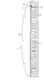
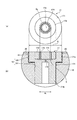
- FIG. 1 is a partial cross-sectional view showing a structure of a heat exchange plate according to an embodiment of the present invention.
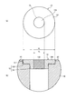
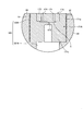
- FIG. 2 is a schematic diagram illustrating a configuration of a main part of the heat exchange plate according to the embodiment of the present invention.
- FIG. 2A is a plan view showing the embedded member 13 of the heat exchange plate.
- FIG. 2B is an enlarged sectional view of the region R shown in FIG.
- the heat exchange plate 1 shown in FIG. 1 includes a disc-shaped main body 10 and a cover 20 that covers one surface (the upper surface in this case) of the main body 10.
- the heat exchange plate 1 is a plate with a flow path inside which a flow path for allowing an inert gas to flow is formed.
- the main body 10 has a disc shape made of aluminum, aluminum alloy, titanium, titanium alloy, stainless steel, nickel alloy, or the like.
- the main body portion 10 is formed with a flow channel 11 for circulating a medium for promoting heat exchange and a flow channel 12 for circulating an inert gas for promoting heat exchange with a target member and discharging the inert gas to the outside.
- the medium is a liquid such as water or a gas.
- the cover 20 is a sprayed film that covers the upper surface of the main body 10 by spraying, and is provided on the opening forming surface of the flow path 12.
- the medium is introduced from a medium inlet port (not shown) and circulated in the flow path 11, and the medium is emitted from a medium outlet port (not shown).
- the heat transferred from the heat source is discharged to the outside via the main body 10 and the cover 20, or the medium absorbing the heat transferred from the heat source is discharged from the flow path.
- an inert gas is introduced from an inert gas introduction port (not shown), the inert gas flows through the flow path 12 and is discharged to the outside. The inert gas contacts and cools the member of interest.
- the flow path 12 has a flow path portion 121, one end of which is connected to the inert gas inlet and forms a flow path inside the main body portion 10, and an opening portion 122 provided at the other end of the flow path portion 121.
- the diameter of the opening 122 is larger than the diameter of the other end of the flow path 121. Therefore, the flow channel 12 has a stepped hole shape near the opening.
- the channel 12 is provided with an embedding member 13 embedded in the opening of the channel 12.
- the embedding member 13 has an embedding portion 131 embedded in the flow path 12 and a circulation portion 132 held by the embedding portion 131.
- the embedded portion 131 is made of ceramic and is formed using a dense body having a porosity of 20% or less.
- the porosity of the embedded portion 131 is preferably 15% or less.
- the embedded portion 131 has a convex outer shape and is housed in the opening 122.
- An insulating ceramic is used as the ceramic.
- the circulation part 132 is a porous ceramic and allows a medium such as a gas to flow from one side to the other side (the vertical direction in FIG. 2).
- a plurality of through holes penetrating one and the other and penetrating the medium are formed in the porous ceramics that constitutes the circulating portion 132.
- the adhesive 14 is provided between the embedded portion 131 and the opening 122, and is fixed by the adhesive 14.
- the adhesive 14 is made of an insulating material.
- the ratio of the outer diameter d 1 to the outer diameter d 2 ( d 1 /d 2 ) is 1.2 or more, preferably 1.5 or more.
- the outer diameter of circulation portion 132 that is, the amount of inert gas released, within the range of the above ratio.
- the circle formed by the outer periphery of the circulation portion 132 (circle Q 1 shown in FIG. 2) corresponds to the smallest circle among the circles formed in the circulation portion 132 and including all through holes.
- the creeping distance of the embedded member 13 in the flow path 12 is a distance along the step formed by the opening 122 and the flow path 121, and thus is a long distance as compared with the related art (see, for example, FIG. 8 ). ing.
- the creepage distance in the flow channel 12 is secured, and the flow channel 12 and the embedding member 13 are fixed by the insulating adhesive 14.
- the overvoltage that has passed through the paths Y1 and Y2 described above is suppressed from entering the main body 10, and as a result, the occurrence of the arcing phenomenon can be suppressed.
- the outer peripheral surface may have an inclined surface that is inclined with respect to the exposed surface exposed from the main body 10, for example. ..
- the embedding member (embedding portion) has a conical shape.
- the heat exchange plate 1 according to the present embodiment is applicable if it has a shape such that the outer diameter is reduced from the side exposed to the outside to the opposite side, such as a convex shape or an inclined surface. It is possible.
- the embedded portion 131 may have a cylindrical shape.
- a stepped portion may be formed in the flow path portion 121 to support the embedded portion 131, or the stepped portion and the embedded portion 131 may not be in contact with each other. From the viewpoint that the embedded portion 131 is not in contact with the step portion of the flow path portion 121 and there is a space (air layer) between the step portion and the embedded portion 131, the entry of overvoltage is suppressed. Is preferred.
- the embedded member 13 has a columnar shape extending in a uniform diameter so that a part of the embedded member 13 (for example, the passage portion entrance portion shown in FIG. 2) does not enter the passage portion 121. Good.
- FIG. 3 is a schematic diagram illustrating a configuration of a main part of the heat exchange plate according to the first modification of the embodiment of the present invention.
- FIG. 3A is a plan view showing the embedded member 15 of the heat exchange plate.
- FIG. 3B is an enlarged cross-sectional view of a region corresponding to the region R shown in FIG.
- the heat exchange plate according to Modification 1 includes an embedding member 15 instead of the embedding member 13 of the heat exchange plate 1 described above.
- the configuration other than the embedded member is the same as that of the heat exchange plate 1 described above, and thus the description thereof is omitted.
- the embedding member 15 has an embedding portion 151 embedded in the flow path 12 and a circulation portion 152 held by the embedding portion 151.
- the embedded portion 151 is made of ceramic and is formed using a dense body having a porosity of 20% or less.
- the embedded portion 151 has a hollow disk shape and is accommodated in the opening 122.
- the circulation part 152 is a porous ceramic and allows a medium such as gas to flow from one side to the other side. A plurality of through holes penetrating one and the other and penetrating the medium are formed in the porous ceramics constituting the circulating portion 152.
- An insulating adhesive 14 is provided between the embedded portion 151 and the opening 122, and is fixed by the adhesive 14.
- the outer diameter d 3 is 1.2 or more, preferably 1.5 or more.
- a circle (circle Q 2 shown in FIG. 3) formed by the outer periphery of the portion of the circulation portion 152 exposed from the cover 20 is formed in the circulation portion 152, and all the through holes penetrating from one side to the other side. It corresponds to the smallest circle among the circles containing.
- the creepage distance of the embedded member 15 in the flow path 12 is a distance along the inner wall of the opening 122, and thus is longer than that of the conventional case (see FIG. 8, for example).
- the heat exchange plate according to the present modification 1 secures the creepage distance in the flow channel 12 and fixes the flow channel 12 and the embedding member 15 with the insulating adhesive 14, It is possible to prevent the overvoltage from passing through the above-described path Y1 from entering the main body portion 10, and as a result, it is possible to suppress the occurrence of the arcing phenomenon. Further, by providing a space (air layer) between the buried portion 151 (circulation portion 152) and the flow passage portion 121, compared with the case where the buried portion 151 and the flow passage portion 121 are in contact with each other, It is possible to prevent the overvoltage from passing through the path Y2 described above from entering the main body 10.
- the outer peripheral surface may have an inclined surface that is inclined with respect to the surface on the annular side.
- the embedding member (embedding portion) has a conical shape.
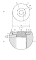
- FIG. 4 is a schematic diagram illustrating a configuration of a main part of the heat exchange plate according to the second modification of the embodiment of the present invention.
- FIG. 4A is a plan view showing the embedded member 16 of the heat exchange plate.
- FIG. 4B is an enlarged sectional view of a region corresponding to the region R shown in FIG.
- the heat exchange plate according to Modification 2 includes an embedding member 16 instead of the embedding member 13 of the heat exchange plate 1 described above.
- the configuration other than the embedded member is the same as that of the heat exchange plate 1 described above, and thus the description thereof is omitted.
- the embedding member 16 has an embedding part 161 embedded in the flow path 12, and a circulation part 162 held by the embedding part 161 and allowing an inert gas to circulate.
- the embedded member 16 is made of ceramic and is formed using a dense body having a porosity of 20% or less.
- a plurality of through holes 163 are formed in the circulation portion 162 to connect the outside and the flow passage portion 121.
- the plurality of through holes 163 are arranged, for example, in an annular shape.
- the embedded portion 161 is a hollow cylindrical column extending in a stepped shape.
- the flow portion 162 has a base portion in which the through hole 163 is formed and an extending portion extending from the central portion of the base portion along the extending direction of the embedded portion 161.
- the distribution unit 162 may not have the extending portion.
- the insulating adhesive 14 is provided between the embedded portion 161 and the opening 122, and is fixed by the adhesive 14. Further, the embedded portion 161 and the circulation portion 162 are fixed to each other, for example, after they are produced, they are integrally sintered to join (join) the contact portions.
- the embedding part 161 and the circulation part 162 may be fixed to each other by a known fixing method.
- the diameter (outer diameter) formed by the outer periphery of the embedded portion 161 is d 5
- the diameter (outer diameter) formed by the circle circumscribing the plurality of through holes 163 (region where the through holes 163 are formed) is d 6
- the ratio of the outer diameter d 5 to the outer diameter d 6 (d 5 /d 6 ) is 1.2 or more, preferably 1.5 or more.
- the “circle circumscribing the plurality of through holes 163” here means the smallest circle among the circles including all the through holes 163.
- the creepage distance of the embedded member 16 in the flow path 12 is a distance along the inner wall of the opening 122, which is a long distance as compared with the conventional case (see FIG. 8, for example).
- the heat exchange plate according to the second modification secures the creepage distance in the flow channel 12 and fixes the flow channel 12 and the embedding member 16 with the insulating adhesive 14. It is possible to prevent the overvoltage from passing through the above-described path Y1 from entering the main body portion 10, and as a result, it is possible to suppress the occurrence of the arcing phenomenon.
- the passage Y2 is used. It is possible to prevent the overvoltage from entering the main body 10.
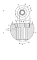
- FIG. 5 is a schematic diagram explaining the structure of the principal part of the heat exchange board concerning the modification 3 of embodiment of this invention.
- FIG. 5A is a plan view showing the embedded member 17 of the heat exchange plate.
- FIG. 5B is an enlarged cross-sectional view of a region corresponding to the region R shown in FIG.
- the heat exchange plate according to Modification 3 includes an embedding member 17 in place of the embedding member 13 of the heat exchange plate 1 described above.
- the configuration other than the embedded member is the same as that of the heat exchange plate 1 described above, and thus the description thereof is omitted.
- the embedding member 17 has an embedding portion 171 that is embedded in the flow path 12, and a circulation portion 172 that is retained by the embedding portion 171 and that allows an inert gas to flow.
- the embedded member 17 is made of ceramic and is formed of a dense body having a porosity of 20% or less.
- Through-holes 173 (second through-holes) that communicate one end side and the other end side are formed in the embedded portion 171.
- a plurality of through holes 174 are formed in the circulation portion 172 to connect the outside and the flow passage portion 121.
- the plurality of through holes 174 are arranged, for example, in an annular shape.
- the circulation part 172 communicates the outside with the flow path part 121 via the through hole 173.
- the embedded portion 171 is a hollow cylindrical column extending in a stepped shape.
- the embedded portion 171 includes a base portion 171a in which a hole for holding the circulation portion 172 and a through hole 173 are formed, and an extending portion 171b extending from the central portion of the base portion 171a in a tubular shape along the extending direction of the embedded portion 171.
- the embedded portion 171 may not have the extending portion 171b.
- the insulating adhesive 14 is provided between the embedded portion 171 and the opening 122, and is fixed by the adhesive 14. Further, the embedded portion 171 and the flow portion 172 are fixed by, for example, manufacturing each of them and then integrally sintering and joining (bonding) the contact portions. The embedding part 171 and the circulation part 172 may be fixed by a known fixing method.
- the formation position of the through hole 173 and the formation position of each through hole 174 are formed at positions deviated from each other. That is, the through hole 173 and the through hole 174 are formed at positions where the central axes of the holes (the central axis in the penetrating direction) do not coincide. Furthermore, the through hole 173 and the through hole 174 are formed at positions where the opening regions do not overlap each other when viewed from the central axis direction.
- the diameter (outer diameter) formed by the outer periphery of the embedded portion 171 is d 7 and the diameter (outer diameter) formed by the circle circumscribing the plurality of through holes 174 (region where the through holes 174 are formed) is d 8
- the ratio of the outer diameter d 7 to the outer diameter d 8 is 1.2 or more, preferably 1.5 or more.
- the “circle circumscribing the plurality of through holes 174” here means the smallest circle among the circles including all the through holes 174.
- the creeping distance of the embedded member 17 in the flow path 12 is a distance along the inner wall of the opening 122, which is a long distance as compared with the conventional case (see FIG. 8, for example).
- the heat exchange plate according to the third modification secures the creepage distance in the flow channel 12 and fixes the flow channel 12 and the embedding member 17 with the insulating adhesive 14, It is possible to prevent the overvoltage from passing through the above-described path Y1 from entering the main body portion 10, and as a result, it is possible to suppress the occurrence of the arcing phenomenon. Further, since the buried portion 171 is present between the circulation portion 172 and the flow passage portion 121, compared to the case where the circulation portion 172 and the flow passage portion 121 are in contact with each other, the passage Y2 is used. It is possible to prevent the overvoltage from entering the main body 10.
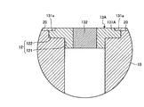
- FIG. 6 is a schematic diagram illustrating a configuration of a main part of a heat exchange plate according to Modification 4 of the embodiment of the present invention.
- FIG. 6 is an enlarged cross-sectional view of a region corresponding to the region R shown in FIG.
- the heat exchange plate according to Modification 4 includes an embedding member 17A in place of the embedding member 13 of the heat exchange plate 1 described above.
- a flow passage 12A is formed instead of the flow passage 12 described above. Since the configuration other than the embedding member and the flow path is the same as that of the heat exchange plate 1 described above, the description thereof will be omitted.
- the flow path 12A has a flow path portion 121A whose one end is connected to the inert gas introduction port and forms a flow path in the main body portion 10, and an opening portion 122A provided at the other end of the flow path portion 121A.
- the diameter of the opening 122A is larger than the diameter of the other end of the flow path 121A. Therefore, the flow path 12A has a stepped hole shape near the opening.
- the channel 12A is provided with an embedding member 17A which is embedded in the opening of the channel 12A.
- the embedding member 17A is made of ceramic and is formed using a dense body having a porosity of 20% or less.
- the embedding member 17A has an embedding portion 171A embedded in the flow path 12A, and a circulation portion 172 held by the embedding portion 171A and allowing an inert gas to flow therethrough.
- the distribution unit 172 is the same as that of the third modification described above, and thus the description thereof is omitted.
- a through hole 173 (second through hole) that connects one end side to the other end side is formed in the embedded portion 171A.
- the embedded portion 171A has a hollow cylindrical shape.
- the embedded portion 171A includes a base portion 171a in which a hole for holding the circulation portion 172 and a through hole 173 are formed, and an extending portion 171c extending from the central portion of the base portion 171a in a tubular shape along the extending direction of the embedded portion 171A. Have.
- the embedded portion 171A may not have the extending portion 171c.
- the embedded portion 171A is placed on the step formed by the flow passage portion 121A and the opening portion 122A, and is housed in the opening portion 122A.
- An insulating adhesive 14 is provided between the buried portion 171A and the opening 122, and is fixed by the adhesive 14.
- the embedded portion 171A and the flow portion 172 are fixed, for example, after each of them is manufactured and integrally sintered to join (join) the contact portions.
- the embedding portion 171A and the circulation portion 172 may be fixed to each other by a known fixing method.
- the formation position of the through hole 173 and the formation position of each through hole 174 are formed at positions displaced from each other.
- the ratio of the diameter (outer diameter) formed by the outer periphery of the embedded portion 171A and the diameter (outer diameter) formed by the circle circumscribing the plurality of through holes 174 (the forming region of the through holes 174) (d 7 / (corresponding to d 8 ) is 1.2 or more, preferably 1.5 or more.
- the creeping distance of the embedding member 17A in the flow path 12A is a distance along the inner wall of the opening 122, which is a long distance as compared with the conventional case (see FIG. 8, for example).
- the heat exchange plate according to the fourth modification secures the creepage distance in the flow channel 12A and fixes the flow channel 12A and the embedding member 17A with the insulating adhesive 14, It is possible to prevent the overvoltage from passing through the above-described path Y1 from entering the main body portion 10, and as a result, it is possible to suppress the occurrence of the arcing phenomenon. Further, since the buried portion 171A is present between the circulation portion 172 and the flow passage portion 121, compared with the case where the circulation portion 172 and the flow passage portion 121 are in contact with each other, the passage Y2 is used. It is possible to prevent the overvoltage from entering the main body 10.
- the heat exchange plate according to the present modification 4 has a stepped shape (for example, modification 3 (see FIG. 5)) because the embedding portion 171A of the embedding member 17A has a cylindrical shape. The manufacturing cost can be reduced.
- FIG. 7 is sectional drawing explaining the structure of the principal part of the heat exchange board concerning the modification 5 of embodiment of this invention.
- FIG. 7 corresponds to an enlarged cross-sectional view of a region corresponding to the region R shown in FIG.
- the heat exchange plate according to Modification 5 includes an embedded member 13A instead of the embedded member 13 of the heat exchange plate 1 described above.
- the configuration other than the embedded member is the same as that of the heat exchange plate 1 described above, and thus the description thereof is omitted.
- the embedded member 13A has an embedded portion 131A embedded in the flow path 12 and a flow portion 132 held by the embedded portion 131A. Since the structure of the distribution unit 132 is the same as that of the above-described embodiment, the description thereof will be omitted.
- the embedded portion 131A is made of ceramic and is formed using a dense body having a porosity of 20% or less.
- the embedded portion 131A has a hollow disc shape and is housed in the opening 122.
- a notch 131a corresponding to the thickness of the cover 20 is formed along the outer edge of the embedded portion 131A on the surface of the embedded portion 131A that is exposed from the main body 10.
- the notch 131a of the buried portion 131A is covered by the cover 20.
- the embedded portion 131A is fixed to the main body portion 10 by the cover 20.
- the ratio of the diameter (outer diameter) formed by the outer circumference of the embedded portion 131A to the diameter (outer diameter) formed by the outer circumference of the portion of the circulation portion 132 exposed from the cover 20 is 1.2 or more, and preferably Is 1.5 or more.
- the heat exchange plate according to the fifth modification secures the creepage distance in the flow path 12, and the flow path 12 and the embedding member 13A are provided by the cover 20 which is a sprayed film instead of the adhesive 14. I fixed it. Also in the fifth modification, the same effect as that of the embodiment can be obtained.
- the heat exchange plate may promote heat exchange for warming the target member.
- a medium such as hot water flows through the flow passage 11
- a gas such as warm air that gives heat flows through the flow passage 12 in the heat exchange plate.
- the heat exchange plate that releases the inert gas that cools the target member has been described as an example, but an inert gas for pressure adjustment used when separating the adsorbed member is used.
- the gas may be released.
- the present invention can be used as a plate with a flow path that releases an inert gas according to the purpose.
- the present invention may include various embodiments and the like not described herein, and various design changes and the like may be made within the scope not departing from the technical idea specified by the claims. Is possible.
- the plate with flow passage according to the present invention is suitable for suppressing the occurrence of arcing phenomenon.
Landscapes
- Engineering & Computer Science (AREA)
- Physics & Mathematics (AREA)
- Thermal Sciences (AREA)
- General Engineering & Computer Science (AREA)
- Mechanical Engineering (AREA)
- General Physics & Mathematics (AREA)
- Microelectronics & Electronic Packaging (AREA)
- Power Engineering (AREA)
- Computer Hardware Design (AREA)
- Manufacturing & Machinery (AREA)
- Condensed Matter Physics & Semiconductors (AREA)
- Geometry (AREA)
- Drying Of Semiconductors (AREA)
- Container, Conveyance, Adherence, Positioning, Of Wafer (AREA)
- Physical Or Chemical Processes And Apparatus (AREA)
Priority Applications (5)
| Application Number | Priority Date | Filing Date | Title |
|---|---|---|---|
| CN201980081476.3A CN113169112B (zh) | 2018-12-14 | 2019-12-03 | 具有流路的板件 |
| JP2020559932A JP7324230B2 (ja) | 2018-12-14 | 2019-12-03 | 流路付きプレート |
| EP19897308.3A EP3896722A4 (en) | 2018-12-14 | 2019-12-03 | FLOW PASSAGE PLATE |
| KR1020217017681A KR102590641B1 (ko) | 2018-12-14 | 2019-12-03 | 유로가 형성된 플레이트 |
| US17/312,110 US20220026151A1 (en) | 2018-12-14 | 2019-12-03 | Plate with flow channel |
Applications Claiming Priority (4)
| Application Number | Priority Date | Filing Date | Title |
|---|---|---|---|
| JP2018-234929 | 2018-12-14 | ||
| JP2018234929 | 2018-12-14 | ||
| JP2019-184146 | 2019-10-04 | ||
| JP2019184146 | 2019-10-04 |
Publications (1)
| Publication Number | Publication Date |
|---|---|
| WO2020121898A1 true WO2020121898A1 (ja) | 2020-06-18 |
Family
ID=71075302
Family Applications (1)
| Application Number | Title | Priority Date | Filing Date |
|---|---|---|---|
| PCT/JP2019/047274 Ceased WO2020121898A1 (ja) | 2018-12-14 | 2019-12-03 | 流路付きプレート |
Country Status (7)
| Country | Link |
|---|---|
| US (1) | US20220026151A1 (enExample) |
| EP (1) | EP3896722A4 (enExample) |
| JP (1) | JP7324230B2 (enExample) |
| KR (1) | KR102590641B1 (enExample) |
| CN (1) | CN113169112B (enExample) |
| TW (1) | TWI747100B (enExample) |
| WO (1) | WO2020121898A1 (enExample) |
Cited By (2)
| Publication number | Priority date | Publication date | Assignee | Title |
|---|---|---|---|---|
| JPWO2024180611A1 (enExample) * | 2023-02-27 | 2024-09-06 | ||
| JP2025159574A (ja) * | 2024-04-08 | 2025-10-21 | 日本特殊陶業株式会社 | 保持装置 |
Families Citing this family (8)
| Publication number | Priority date | Publication date | Assignee | Title |
|---|---|---|---|---|
| KR20230036346A (ko) | 2021-09-07 | 2023-03-14 | 선문대학교 산학협력단 | Cyp125a13 효소를 이용한 스테로이드의 히드록시화 생물전환 방법 |
| KR20230036348A (ko) | 2021-09-07 | 2023-03-14 | 선문대학교 산학협력단 | 7α-히드록시스테로이드 탈수소 효소를 이용한 스테로이드의 탈수소화 생물전환 방법 |
| KR102823387B1 (ko) | 2021-09-07 | 2025-06-23 | 선문대학교 산학협력단 | CYP154C3s 효소를 이용한 스테로이드의 하이드록시화 생물전환 방법 |
| KR102638205B1 (ko) | 2021-09-13 | 2024-02-20 | 선문대학교 산학협력단 | Cyp105d18 효소를 이용한 이소퀴놀린 알칼로이드 화합물의 n-산화 생물전환 방법 |
| KR102854914B1 (ko) * | 2021-10-20 | 2025-09-03 | 니혼도꾸슈도교 가부시키가이샤 | 유지 장치 |
| CN118280801A (zh) * | 2022-12-29 | 2024-07-02 | 中微半导体设备(上海)股份有限公司 | 一种多孔塞组件、静电吸盘及等离子体刻蚀装置 |
| KR102685150B1 (ko) * | 2023-10-12 | 2024-07-16 | 주식회사 미코세라믹스 | 세라믹 서셉터 및 그 제조 방법 |
| KR102823869B1 (ko) | 2024-08-26 | 2025-06-23 | 주식회사 리더티앤디 | Mdf용 분체 도장 자동화 시스템 |
Citations (6)
| Publication number | Priority date | Publication date | Assignee | Title |
|---|---|---|---|---|
| JP2003338492A (ja) * | 2002-05-21 | 2003-11-28 | Tokyo Electron Ltd | プラズマ処理装置 |
| JP2006344766A (ja) * | 2005-06-09 | 2006-12-21 | Matsushita Electric Ind Co Ltd | プラズマ処理装置 |
| JP3154629U (ja) * | 2009-08-04 | 2009-10-22 | 日本碍子株式会社 | 静電チャック |
| JP2010123712A (ja) * | 2008-11-19 | 2010-06-03 | Nihon Ceratec Co Ltd | 静電チャックおよびその製造方法 |
| JP2014209615A (ja) | 2013-03-29 | 2014-11-06 | Toto株式会社 | 静電チャック |
| JP2017135351A (ja) * | 2016-01-29 | 2017-08-03 | 日本特殊陶業株式会社 | 基板支持装置及びその製造方法 |
Family Cites Families (10)
| Publication number | Priority date | Publication date | Assignee | Title |
|---|---|---|---|---|
| JP2559123Y2 (ja) * | 1992-03-31 | 1998-01-14 | 株式会社神戸製鋼所 | 真空アーク蒸着装置 |
| US6108189A (en) * | 1996-04-26 | 2000-08-22 | Applied Materials, Inc. | Electrostatic chuck having improved gas conduits |
| JP3965258B2 (ja) * | 1999-04-30 | 2007-08-29 | 日本碍子株式会社 | 半導体製造装置用のセラミックス製ガス供給構造 |
| US6490145B1 (en) * | 2001-07-18 | 2002-12-03 | Applied Materials, Inc. | Substrate support pedestal |
| JP5331519B2 (ja) * | 2008-03-11 | 2013-10-30 | 日本碍子株式会社 | 静電チャック |
| JP4590597B2 (ja) * | 2008-03-12 | 2010-12-01 | 国立大学法人東北大学 | シャワープレートの製造方法 |
| MY154101A (en) * | 2008-11-26 | 2015-04-30 | Nhk Spring Co Ltd | Probe-unit base member and probe unit |
| JP6263484B2 (ja) * | 2015-01-30 | 2018-01-17 | 日本特殊陶業株式会社 | 静電チャックおよびその製造方法 |
| JP6257540B2 (ja) * | 2015-01-30 | 2018-01-10 | 日本特殊陶業株式会社 | 静電チャックおよびその製造方法 |
| CN108649012B (zh) * | 2018-05-11 | 2021-10-01 | 北京华卓精科科技股份有限公司 | 新型陶瓷塞及具有该新型陶瓷塞的静电卡盘装置 |
-
2019
- 2019-12-03 JP JP2020559932A patent/JP7324230B2/ja active Active
- 2019-12-03 US US17/312,110 patent/US20220026151A1/en active Pending
- 2019-12-03 WO PCT/JP2019/047274 patent/WO2020121898A1/ja not_active Ceased
- 2019-12-03 EP EP19897308.3A patent/EP3896722A4/en active Pending
- 2019-12-03 CN CN201980081476.3A patent/CN113169112B/zh active Active
- 2019-12-03 KR KR1020217017681A patent/KR102590641B1/ko active Active
- 2019-12-12 TW TW108145427A patent/TWI747100B/zh active
Patent Citations (6)
| Publication number | Priority date | Publication date | Assignee | Title |
|---|---|---|---|---|
| JP2003338492A (ja) * | 2002-05-21 | 2003-11-28 | Tokyo Electron Ltd | プラズマ処理装置 |
| JP2006344766A (ja) * | 2005-06-09 | 2006-12-21 | Matsushita Electric Ind Co Ltd | プラズマ処理装置 |
| JP2010123712A (ja) * | 2008-11-19 | 2010-06-03 | Nihon Ceratec Co Ltd | 静電チャックおよびその製造方法 |
| JP3154629U (ja) * | 2009-08-04 | 2009-10-22 | 日本碍子株式会社 | 静電チャック |
| JP2014209615A (ja) | 2013-03-29 | 2014-11-06 | Toto株式会社 | 静電チャック |
| JP2017135351A (ja) * | 2016-01-29 | 2017-08-03 | 日本特殊陶業株式会社 | 基板支持装置及びその製造方法 |
Cited By (6)
| Publication number | Priority date | Publication date | Assignee | Title |
|---|---|---|---|---|
| JPWO2024180611A1 (enExample) * | 2023-02-27 | 2024-09-06 | ||
| WO2024180611A1 (ja) * | 2023-02-27 | 2024-09-06 | 日本碍子株式会社 | ウエハ載置台 |
| JP7657310B2 (ja) | 2023-02-27 | 2025-04-04 | 日本碍子株式会社 | ウエハ載置台 |
| US12451385B2 (en) | 2023-02-27 | 2025-10-21 | Ngk Insulators, Ltd. | Wafer placement table |
| JP2025159574A (ja) * | 2024-04-08 | 2025-10-21 | 日本特殊陶業株式会社 | 保持装置 |
| JP7784470B2 (ja) | 2024-04-08 | 2025-12-11 | 日本特殊陶業株式会社 | 保持装置 |
Also Published As
| Publication number | Publication date |
|---|---|
| EP3896722A4 (en) | 2022-08-24 |
| KR20210087536A (ko) | 2021-07-12 |
| TWI747100B (zh) | 2021-11-21 |
| US20220026151A1 (en) | 2022-01-27 |
| JPWO2020121898A1 (ja) | 2021-11-25 |
| CN113169112B (zh) | 2024-05-07 |
| KR102590641B1 (ko) | 2023-10-17 |
| EP3896722A1 (en) | 2021-10-20 |
| TW202025414A (zh) | 2020-07-01 |
| JP7324230B2 (ja) | 2023-08-09 |
| CN113169112A (zh) | 2021-07-23 |
Similar Documents
| Publication | Publication Date | Title |
|---|---|---|
| WO2020121898A1 (ja) | 流路付きプレート | |
| JP7682966B2 (ja) | Umベース構成 | |
| US10279441B2 (en) | Method of manufacturing plate with passage, plate with passage, temperature adjustment plate, cold plate, and shower plate | |
| JP6865145B2 (ja) | 保持装置 | |
| TWI503441B (zh) | 包含複數個擴散熔接盤之氣體分配器以及此種氣體分配器之製造方法 | |
| JP7752715B2 (ja) | Cvdリアクタ用のガス入口装置 | |
| JP2009218280A (ja) | 半導体装置 | |
| KR20150122699A (ko) | 저 열팽창 계수의 정상부를 갖는 받침부 구성 | |
| JP2022003667A (ja) | 保持装置 | |
| JP2018110148A (ja) | 真空吸着部材 | |
| TW202020215A (zh) | 具有嵌入式加熱器的面板 | |
| JP7017273B2 (ja) | 半導体処理装置 | |
| WO2018198356A1 (ja) | ベーパーチャンバー | |
| KR100699738B1 (ko) | 열 보상 히터 모듈을 구비한 레이저 열처리 척 | |
| JP7299805B2 (ja) | 保持装置 | |
| US20160227637A1 (en) | Filter and target supply apparatus | |
| JP7573117B1 (ja) | ウエハ載置台 | |
| KR102699420B1 (ko) | 웨이퍼 적재대 | |
| WO2024241516A1 (ja) | ウエハ載置台 | |
| JP2024036802A (ja) | 静電チャック装置 | |
| JP6014994B2 (ja) | プラズマ処理装置用電極板 | |
| JP2012119590A (ja) | プラズマ処理装置用電極板 | |
| JP2023079422A (ja) | ウエハ載置台 | |
| JP7692811B2 (ja) | 試料保持具 | |
| JP7717026B2 (ja) | 保持装置及び静電チャック |
Legal Events
| Date | Code | Title | Description |
|---|---|---|---|
| 121 | Ep: the epo has been informed by wipo that ep was designated in this application |
Ref document number: 19897308 Country of ref document: EP Kind code of ref document: A1 |
|
| DPE1 | Request for preliminary examination filed after expiration of 19th month from priority date (pct application filed from 20040101) | ||
| ENP | Entry into the national phase |
Ref document number: 2020559932 Country of ref document: JP Kind code of ref document: A |
|
| ENP | Entry into the national phase |
Ref document number: 20217017681 Country of ref document: KR Kind code of ref document: A |
|
| NENP | Non-entry into the national phase |
Ref country code: DE |
|
| ENP | Entry into the national phase |
Ref document number: 2019897308 Country of ref document: EP Effective date: 20210714 |