WO2020116506A1 - 動力伝達装置 - Google Patents
動力伝達装置 Download PDFInfo
- Publication number
- WO2020116506A1 WO2020116506A1 PCT/JP2019/047407 JP2019047407W WO2020116506A1 WO 2020116506 A1 WO2020116506 A1 WO 2020116506A1 JP 2019047407 W JP2019047407 W JP 2019047407W WO 2020116506 A1 WO2020116506 A1 WO 2020116506A1
- Authority
- WO
- WIPO (PCT)
- Prior art keywords
- clutch
- power transmission
- clutch plate
- pressure
- transmission device
- Prior art date
- Legal status (The legal status is an assumption and is not a legal conclusion. Google has not performed a legal analysis and makes no representation as to the accuracy of the status listed.)
- Ceased
Links
Images


Classifications
-
- F—MECHANICAL ENGINEERING; LIGHTING; HEATING; WEAPONS; BLASTING
- F16—ENGINEERING ELEMENTS AND UNITS; GENERAL MEASURES FOR PRODUCING AND MAINTAINING EFFECTIVE FUNCTIONING OF MACHINES OR INSTALLATIONS; THERMAL INSULATION IN GENERAL
- F16D—COUPLINGS FOR TRANSMITTING ROTATION; CLUTCHES; BRAKES
- F16D13/00—Friction clutches
- F16D13/58—Details
- F16D13/60—Clutching elements
-
- F—MECHANICAL ENGINEERING; LIGHTING; HEATING; WEAPONS; BLASTING
- F16—ENGINEERING ELEMENTS AND UNITS; GENERAL MEASURES FOR PRODUCING AND MAINTAINING EFFECTIVE FUNCTIONING OF MACHINES OR INSTALLATIONS; THERMAL INSULATION IN GENERAL
- F16D—COUPLINGS FOR TRANSMITTING ROTATION; CLUTCHES; BRAKES
- F16D43/00—Automatic clutches
- F16D43/02—Automatic clutches actuated entirely mechanically
- F16D43/04—Automatic clutches actuated entirely mechanically controlled by angular speed
- F16D43/06—Automatic clutches actuated entirely mechanically controlled by angular speed with centrifugal masses actuating axially a movable pressure ring or the like
- F16D43/08—Automatic clutches actuated entirely mechanically controlled by angular speed with centrifugal masses actuating axially a movable pressure ring or the like the pressure ring actuating friction plates, cones or similar axially-movable friction surfaces
- F16D43/12—Automatic clutches actuated entirely mechanically controlled by angular speed with centrifugal masses actuating axially a movable pressure ring or the like the pressure ring actuating friction plates, cones or similar axially-movable friction surfaces the centrifugal masses acting on, or forming a part of, an actuating mechanism by which the pressure ring can also be actuated independently of the masses
-
- F—MECHANICAL ENGINEERING; LIGHTING; HEATING; WEAPONS; BLASTING
- F16—ENGINEERING ELEMENTS AND UNITS; GENERAL MEASURES FOR PRODUCING AND MAINTAINING EFFECTIVE FUNCTIONING OF MACHINES OR INSTALLATIONS; THERMAL INSULATION IN GENERAL
- F16D—COUPLINGS FOR TRANSMITTING ROTATION; CLUTCHES; BRAKES
- F16D13/00—Friction clutches
- F16D13/22—Friction clutches with axially-movable clutching members
- F16D13/38—Friction clutches with axially-movable clutching members with flat clutching surfaces, e.g. discs
- F16D13/52—Clutches with multiple lamellae ; Clutches in which three or more axially moveable members are fixed alternately to the shafts to be coupled and are pressed from one side towards an axially-located member
- F16D13/54—Clutches with multiple lamellae ; Clutches in which three or more axially moveable members are fixed alternately to the shafts to be coupled and are pressed from one side towards an axially-located member with means for increasing the effective force between the actuating sleeve or equivalent member and the pressure member
- F16D13/56—Clutches with multiple lamellae ; Clutches in which three or more axially moveable members are fixed alternately to the shafts to be coupled and are pressed from one side towards an axially-located member with means for increasing the effective force between the actuating sleeve or equivalent member and the pressure member in which the clutching pressure is produced by springs only
-
- B—PERFORMING OPERATIONS; TRANSPORTING
- B60—VEHICLES IN GENERAL
- B60K—ARRANGEMENT OR MOUNTING OF PROPULSION UNITS OR OF TRANSMISSIONS IN VEHICLES; ARRANGEMENT OR MOUNTING OF PLURAL DIVERSE PRIME-MOVERS IN VEHICLES; AUXILIARY DRIVES FOR VEHICLES; INSTRUMENTATION OR DASHBOARDS FOR VEHICLES; ARRANGEMENTS IN CONNECTION WITH COOLING, AIR INTAKE, GAS EXHAUST OR FUEL SUPPLY OF PROPULSION UNITS IN VEHICLES
- B60K17/00—Arrangement or mounting of transmissions in vehicles
- B60K17/02—Arrangement or mounting of transmissions in vehicles characterised by arrangement, location, or kind of clutch
-
- F—MECHANICAL ENGINEERING; LIGHTING; HEATING; WEAPONS; BLASTING
- F16—ENGINEERING ELEMENTS AND UNITS; GENERAL MEASURES FOR PRODUCING AND MAINTAINING EFFECTIVE FUNCTIONING OF MACHINES OR INSTALLATIONS; THERMAL INSULATION IN GENERAL
- F16D—COUPLINGS FOR TRANSMITTING ROTATION; CLUTCHES; BRAKES
- F16D13/00—Friction clutches
- F16D13/22—Friction clutches with axially-movable clutching members
- F16D13/38—Friction clutches with axially-movable clutching members with flat clutching surfaces, e.g. discs
- F16D13/52—Clutches with multiple lamellae ; Clutches in which three or more axially moveable members are fixed alternately to the shafts to be coupled and are pressed from one side towards an axially-located member
-
- F—MECHANICAL ENGINEERING; LIGHTING; HEATING; WEAPONS; BLASTING
- F16—ENGINEERING ELEMENTS AND UNITS; GENERAL MEASURES FOR PRODUCING AND MAINTAINING EFFECTIVE FUNCTIONING OF MACHINES OR INSTALLATIONS; THERMAL INSULATION IN GENERAL
- F16D—COUPLINGS FOR TRANSMITTING ROTATION; CLUTCHES; BRAKES
- F16D13/00—Friction clutches
- F16D13/58—Details
-
- F—MECHANICAL ENGINEERING; LIGHTING; HEATING; WEAPONS; BLASTING
- F16—ENGINEERING ELEMENTS AND UNITS; GENERAL MEASURES FOR PRODUCING AND MAINTAINING EFFECTIVE FUNCTIONING OF MACHINES OR INSTALLATIONS; THERMAL INSULATION IN GENERAL
- F16D—COUPLINGS FOR TRANSMITTING ROTATION; CLUTCHES; BRAKES
- F16D43/00—Automatic clutches
- F16D43/02—Automatic clutches actuated entirely mechanically
- F16D43/20—Automatic clutches actuated entirely mechanically controlled by torque, e.g. overload-release clutches, slip-clutches with means by which torque varies the clutching pressure
- F16D43/202—Automatic clutches actuated entirely mechanically controlled by torque, e.g. overload-release clutches, slip-clutches with means by which torque varies the clutching pressure of the ratchet type
- F16D43/204—Automatic clutches actuated entirely mechanically controlled by torque, e.g. overload-release clutches, slip-clutches with means by which torque varies the clutching pressure of the ratchet type with intermediate balls or rollers
- F16D43/206—Automatic clutches actuated entirely mechanically controlled by torque, e.g. overload-release clutches, slip-clutches with means by which torque varies the clutching pressure of the ratchet type with intermediate balls or rollers moving axially between engagement and disengagement
-
- F—MECHANICAL ENGINEERING; LIGHTING; HEATING; WEAPONS; BLASTING
- F16—ENGINEERING ELEMENTS AND UNITS; GENERAL MEASURES FOR PRODUCING AND MAINTAINING EFFECTIVE FUNCTIONING OF MACHINES OR INSTALLATIONS; THERMAL INSULATION IN GENERAL
- F16D—COUPLINGS FOR TRANSMITTING ROTATION; CLUTCHES; BRAKES
- F16D67/00—Combinations of couplings and brakes; Combinations of clutches and brakes
- F16D67/02—Clutch-brake combinations
-
- F—MECHANICAL ENGINEERING; LIGHTING; HEATING; WEAPONS; BLASTING
- F16—ENGINEERING ELEMENTS AND UNITS; GENERAL MEASURES FOR PRODUCING AND MAINTAINING EFFECTIVE FUNCTIONING OF MACHINES OR INSTALLATIONS; THERMAL INSULATION IN GENERAL
- F16D—COUPLINGS FOR TRANSMITTING ROTATION; CLUTCHES; BRAKES
- F16D13/00—Friction clutches
- F16D13/22—Friction clutches with axially-movable clutching members
- F16D13/38—Friction clutches with axially-movable clutching members with flat clutching surfaces, e.g. discs
- F16D13/52—Clutches with multiple lamellae ; Clutches in which three or more axially moveable members are fixed alternately to the shafts to be coupled and are pressed from one side towards an axially-located member
- F16D13/54—Clutches with multiple lamellae ; Clutches in which three or more axially moveable members are fixed alternately to the shafts to be coupled and are pressed from one side towards an axially-located member with means for increasing the effective force between the actuating sleeve or equivalent member and the pressure member
- F16D13/56—Clutches with multiple lamellae ; Clutches in which three or more axially moveable members are fixed alternately to the shafts to be coupled and are pressed from one side towards an axially-located member with means for increasing the effective force between the actuating sleeve or equivalent member and the pressure member in which the clutching pressure is produced by springs only
- F16D2013/565—Clutches with multiple lamellae ; Clutches in which three or more axially moveable members are fixed alternately to the shafts to be coupled and are pressed from one side towards an axially-located member with means for increasing the effective force between the actuating sleeve or equivalent member and the pressure member in which the clutching pressure is produced by springs only with means for releasing the clutch pressure in case of back torque
Definitions
- the present invention relates to a power transmission device capable of arbitrarily transmitting or blocking the rotational force of an input member to an output member.
- a power transmission device included in a motorcycle is for arbitrarily transmitting or cutting off a driving force of an engine to a mission and drive wheels, and an input member connected to the engine side and a transmission and drive wheel side. It has a connected output member, a clutch member connected to the output member, and a pressure member that can approach or separate from the clutch member.
- the side clutch plate and the driven side clutch plate are brought into pressure contact with each other to transmit power, and the pressure member is separated from the clutch member to release the pressure contact force between the driving side clutch plate and the driven side clutch plate.
- the transmission of the power is cut off.
- a centrifugal force associated with rotation of a clutch housing moves from an inner diameter side position of the groove portion to an outer diameter side position of the groove to drive the clutch plate and the driven side. It has been proposed to provide a weight member that can be brought into pressure contact with the side clutch plate. According to such a conventional power transmission device, a centrifugal force can be applied to the weight member by rotating the clutch housing with the driving of the engine, and the drive side clutch plate and the driven side clutch plate are brought into pressure contact with each other. The driving force of the engine can be transmitted to the wheels.
- the conventional power transmission device is compressed as the interlocking member moves and the pressure member moves from the non-actuated position to the actuated position, and the drive-side clutch plate and the driven-side clutch plate are not pressed against each other.
- a clutch spring capable of applying a pressure contact force to the driving side clutch plate and the driven side clutch plate while allowing the movement of the interlocking member.
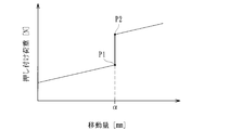
- the above conventional power transmission device has the following problems. There is a difference between the load at the end of compression of the release spring (maximum load) (see P1 in FIG. 32) and the load at the start of compression of the clutch spring (set load) (see P2 in the same figure).
- maximum load see P1 in FIG. 32
- set load see P2 in the same figure.
- the clutch spring is compressed after the release spring is compressed in the process in which the interlocking member moves as the engine speed increases and the pressure member moves from the non-operating position to the operating position.
- the dead zone region in which the movement of the interlocking member stops stops at the movement amount ⁇ in the figure) occurs before the start of the.
- the applicant of the present invention has a first clutch member that is configured by dividing the clutch member into two in order to favorably generate engine braking, and that is connected to the output member, and a second clutch member to which the driven side clutch plate is attached. And a back torque transmitting cam capable of moving the second clutch member to bring the driving side clutch plate and the driven side clutch plate into pressure contact when a rotational force is input to the first clutch member via the output member.
- a power transmission device is being studied, and when arranging a means for suppressing a sudden feeling, it is necessary to effectively use the space obtained by disposing such a first clutch member and a second clutch member. We came to a thorough examination.
- the present invention has been made in view of the above circumstances, and effectively operates the space obtained by disposing the first clutch member and the second clutch member while suppressing a feeling of sudden collision during power transmission. It is to provide a power transmission device capable of improving the property.
- a clutch housing which rotates together with an input member that is rotated by a driving force of an engine of a vehicle and has a plurality of drive side clutch plates attached thereto, and a drive side clutch plate of the clutch housing are alternately formed.
- a plurality of driven side clutch plates are attached, and a clutch member connected to an output member capable of rotating the wheels of the vehicle, the driving side clutch plate and the driven side clutch plate are brought into pressure contact with each other, and the driving force of the engine is increased.
- Non-actuated position in which the driving force of the engine can be transmitted to the wheel and non-operation that can release the pressure contact force between the driving side clutch plate and the driven side clutch plate to block transmission of the driving force of the engine to the wheel
- a pressure member movable between a position and a radially extending groove of the clutch housing, the centrifugal force accompanying the rotation of the clutch housing causes the centrifugal force to rotate from the inner diameter side to the outer diameter side.
- a weight member movable to a position, and an interlocking member capable of moving the pressure member from the non-operating position to the operating position as the weight member moves from the inner diameter side position to the outer diameter side position.
- the pressure member can be held in the non-actuated position, the interlocking member is moved, and the pressure member is compressed as the pressure member moves from the non-actuated position toward the actuated position.
- a release spring that can apply a biasing force while allowing the movement of the interlocking member and the pressure member until the engaged state before the driven side clutch plate is pressed is reached, and the drive side clutch plate and the driven side clutch plate are
- a clutch spring which is compressed in the process of moving the interlocking member after reaching the engaged state and which can apply the pressure contact force of the driving side clutch plate and the driven side clutch plate while permitting the movement of the interlocking member.
- the clutch member rotates to the first clutch member via the first clutch member connected to the output member, the second clutch member to which the driven side clutch plate is attached, and the output member.
- a force is input, it has a back torque transmitting cam that moves the second clutch member to press the driving side clutch plate and the driven side clutch plate into pressure contact, and the first clutch member and the second clutch.
- a biasing force is provided while allowing the movement of the interlocking member and the pressure member by being interposed between the interlocking member and the member and compressing in the process in which the interlocking member moves and the pressure member moves from the non-operating position to the operating position.
- Possible buffer It is characterized by comprising a member.
- the invention according to claim 2 is the power transmission device according to claim 1, wherein the buffer member is a spring set to a load that is compressed before the clutch spring starts to be compressed.
- the buffer member is housed in a housing recess formed on a surface facing the first clutch member and the second clutch member. It is characterized by
- the accommodating recess includes a groove formed in an annular shape, and the buffer member is formed in an annular shape following the groove shape. It is characterized by comprising a spring.
- a plurality of the back torque transmitting cams are formed in an annular shape on a surface where the first clutch member and the second clutch member face each other,
- the accommodation recess is concentrically formed at a position adjacent to the back torque transmitting cam.
- the interlocking member is interposed between the first clutch member and the second clutch member, and the interlocking member moves to compress the pressure member in the process from the non-actuated position to the actuated position. Also, since the cushioning member that can apply the biasing force while allowing the movement of the pressure member is provided, the space obtained with the disposition of the first clutch member and the second clutch member is effectively used, and abruptly during power transmission. The feeling can be suppressed and the operability can be improved.
- the cushioning member is composed of a spring set to a load that is compressed before the clutch spring starts to be compressed, it is possible to more reliably suppress the sudden feeling during power transmission.
- the second clutch member since the buffer member is housed in the housing recess formed in the surface where the first clutch member and the second clutch member face each other, the second clutch member is It is possible to prevent the cushioning member from being caught and causing a positional deviation when moving.
- the accommodating recess includes a groove formed in an annular shape
- the buffer member includes a spring formed in an annular shape following the groove shape.
- the biasing force can be applied to the second clutch member and the like substantially uniformly, and the biasing force can be stably applied.
- a plurality of back torque transmission cams are formed in an annular shape on the surface where the first clutch member and the second clutch member face each other, and the accommodation recess is formed with the back torque transmission cam. Since the concentric circles are formed at the adjacent positions, the movement of the second clutch member by the back torque transmitting cam and the application of the urging force by the buffer member can be reliably and stably performed.
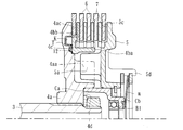
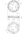
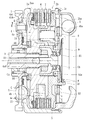
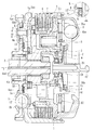
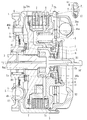
- FIG. 3 is a vertical cross-sectional view showing the internal configuration of the power transmission device.
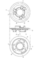
- 3 side view which shows the 1st clutch member in the same power transmission device 3 side view which shows the 2nd clutch member in the same power transmission device
- Three-sided view showing a pressure member in the power transmission device
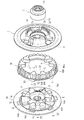
- the perspective view showing the state before the first clutch member, the second clutch member, the pressure member, and the bearing holding member in the power transmission device are assembled.
- the perspective view showing the state before the first clutch member, the second clutch member, the pressure member, and the bearing holding member in the power transmission device are assembled.
- a perspective view showing a state after the first clutch member, the second clutch member, the pressure member, and the bearing holding member are assembled in the power transmission device.
- FIG. 3 is a diagram showing a state in which the first clutch member and the second clutch member are assembled in the power transmission device, and a plan view showing a state in which one side surface of the convex portion and the first contact surface (torque transmitting portion) are in contact with each other.
- FIG. 3 is a diagram showing a state in which the first clutch member and the second clutch member are assembled in the power transmission device, and a plan view showing a state in which one side surface of the convex portion and the first contact surface (torque transmitting portion) are in contact with each other.
- FIG. 3 is a view showing a state in which the first clutch member and the second clutch member are assembled in the power transmission device, and is a plane view showing a state in which the other side surface of the convex portion and the second contact surface (movement amount limiting portion) are in contact with each other.
- Figure FIG. 6 is a diagram for explaining the action of the back torque transmission cam in the power transmission device, and is a schematic diagram showing a state before the back torque transmission cam is activated.
- FIG. 6 is a diagram for explaining the action of the back torque transmission cam in the power transmission device, which is a schematic diagram showing a state after the back torque transmission cam has operated.
- the schematic diagram which shows the state which the buffer member in the same power transmission device accommodated in the accommodation recessed part.
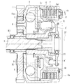
- FIG. 3 is a vertical sectional view showing a power transmission device according to another embodiment of the present invention.
- FIG. 3 is a vertical sectional view showing a power transmission device according to another embodiment of the present invention.
- FIG. 3 is a vertical sectional view showing a power transmission device according to another embodiment of the present invention.
- FIG. 3 is a vertical sectional view showing a power transmission device according to another embodiment of the present invention.
- FIG. 3 is a vertical sectional view showing a power transmission device according to another embodiment of the present invention.
- FIG. 3 is a vertical sectional view showing a power transmission device according to another embodiment of the present invention.
- FIG. 6 is a vertical cross-sectional view showing a power transmission device (where a cushioning member 12 ′ is arranged) according to another embodiment of the present invention.
- the top view and side view which show the buffer member in the same power transmission device.
- the perspective view which shows the buffer member in the power transmission device.
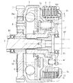
- FIG. 3 is a vertical cross-sectional view showing a power transmission device according to another embodiment of the present invention (a cam for back torque transmission is provided at an outer edge portion of the first clutch member 4a, and a buffer member made of a disc spring is provided).
- FIG 3 is a vertical cross-sectional view showing a power transmission device according to another embodiment of the present invention (a cam for back torque transmission is provided at an outer edge portion of the first clutch member 4a, and a buffer member made of a wave spring is provided).
- the graph which shows the moving amount and pressing load of the interlocking member in the conventional power transmission device.
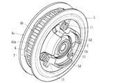
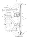
- the power transmission device is arranged in a vehicle such as a two-wheeled vehicle and is used to arbitrarily transmit or cut off the driving force of the engine to the mission side or the driving wheel side, and as shown in FIGS. ,
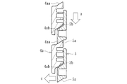
- a clutch housing 2 in which an input gear 1 (input member) that is rotated by a driving force of an engine of a vehicle is formed, a clutch member (first clutch member 4a and second clutch member 4b), and a clutch member (first clutch member) 4a and the second clutch member 4b), the pressure member 5 attached to the right side in FIG.
- the weight member 8 is composed of a movable steel ball member, an interlocking member 9, and an actuating member 10 operable by a manual operation or an actuator (not shown).
- reference symbol S indicates a spring damper
- reference symbol B1 indicates a roller bearing
- reference symbols B2 and B3 indicate a thrust bearing.
- the input gear 1 is rotatable around the output shaft 3 when the driving force (rotational force) transmitted from the engine is input, and is connected to the clutch housing 2 by a rivet R or the like.
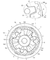
- the clutch housing 2 is made of a cylindrical member having an opening on the right end side in FIG. 2, and has a housing portion 2a connected to the input gear 1 and a cover portion 2b attached so as to close the opening of the housing portion 2a.
- the input gear 1 is rotated by the driving force of the engine.
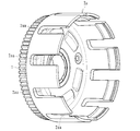
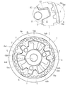
- the casing 2a of the clutch housing 2 is formed with a plurality of notches 2aa in the circumferential direction, and the notches 2aa are fitted into the plurality of drive side clutch plates. 6 is attached.
- Each of the drive-side clutch plates 6 is made of a plate material formed in a substantially annular shape, is configured to rotate with the rotation of the clutch housing 2, and is configured to be slidable in the axial direction (the horizontal direction in FIG. 2). There is.
- the cover portion 2b of the clutch housing 2 is formed with a plurality of groove portions 2ba extending in the radial direction of the cover portion 2b on the bottom surface thereof.
- a weight member 8 is provided in each of the groove portions 2ba, and when the clutch housing 2 is stopped (engine stopped or idling state) and rotated at a low speed, the weight member 8 is located at the inner diameter side position (FIG. 2). Position) and the weight member 8 is set to the outer diameter side position when the clutch housing 2 rotates at a high speed.
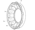
- the clutch members (the first clutch member 4a and the second clutch member 4b) are mounted with a plurality of driven side clutch plates 7 that are alternately formed with the drive side clutch plates 6 of the clutch housing 2 and rotate the wheels of the vehicle. It is connected to the output shaft 3 (output member) to be obtained, and is configured by assembling two members, a first clutch member 4a and a second clutch member 4b.
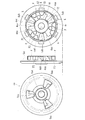
- the first clutch member 4a is composed of a disc-shaped member having a flange surface 4ac formed along the peripheral edge thereof, and has an insertion hole 4ad formed in the center thereof (see FIGS. 2 and 6). ), the output shaft 3 is inserted, and gears formed with each other mesh with each other and are connected in the rotational direction.
- the first clutch member 4a is formed with a sloped surface 4aa forming a pressure contact assist cam and a sloped surface 4ab forming a back torque limiter cam.
- the second clutch member 4b is composed of an annular member, and the driven side clutch plate 7 is spline-fitted to the spline fitting portion 4ba (see FIGS. 2 and 7) formed on the outer peripheral surface. It is configured to be attached at.
- the pressure member 5 is assembled to the clutch members (the first clutch member 4a and the second clutch member 4b), and the flange surface 5c of the pressure member 5 (see FIGS. 2 and 8).
- the flange surface 4ac see FIGS. 2 and 6 of the first clutch member 4a, a plurality of drive side clutch plates 6 and driven side clutch plates 7 are alternately mounted in a laminated state.
- the pressure member 5 is composed of a disc-shaped member having a flange surface 5c formed along the peripheral edge thereof, and the drive-side clutch plate 6 and the driven-side clutch plate 7 are brought into pressure contact with each other.
- the operating position that allows the driving force of the engine to be transmitted to the wheels and the pressure contact force between the driving side clutch plate 6 and the driven side clutch plate 7 are released to prevent the driving force of the engine from being transmitted to the wheels. It is movable to and from the obtained non-actuated position (see FIG. 2).
- the spline fitting portion 4ba formed on the second clutch member 4b is integrated over substantially the entire circumference of the outer circumferential side surface of the second clutch member 4b.
- the driven-side clutch plate 7 is fitted into the concave groove that forms the spline fitting portion 4ba, so that the driven-side clutch plate 7 has a shaft relative to the second clutch member 4b.
- the movement in the rotation direction is restricted while allowing the movement in the direction, and the second clutch member 4b is configured to rotate together.
- the driven clutch plate 7 and the driving clutch plate 6 are alternately laminated so that the adjacent clutch plates 6 and 7 can be pressed or released. That is, both the clutch plates 6 and 7 are allowed to slide in the axial direction of the second clutch member 4b, and the pressure member 5 moves to the left side in FIG. 2 to move the flange surface 5c and the first clutch member 4a.
- the flange surface 4ac of the clutch housing 2 approaches, the clutch plates 6 and 7 are pressed against each other, and the rotational force of the clutch housing 2 is transmitted to the output shaft 3 via the second clutch member 4b and the first clutch member 4a.
- the member 5 moves to the right side in FIG.
- the first clutch member 4a is formed with sloped surfaces 4aa and 4ab, and the pressure member 5 is formed with these sloped surfaces 4aa. And sloped surfaces 5a and 5b facing 4ab are formed. That is, the sloped surface 4aa and the sloped surface 5a are in contact with each other to form a press-contact assist cam, and the sloped surface 4ab and the sloped surface 5b are in contact with each other to form a back torque limiter cam.
- the weight member 8 is disposed in the groove portion 2ba extending in the radial direction of the clutch housing 2 (the cover portion 2b in the present embodiment), and the inner diameter of the groove portion 2ba is generated by the centrifugal force generated by the rotation of the clutch housing 2.
- the driving side clutch plate 6 and the driven side clutch plate 7 can be pressed against each other. That is, the rolling surface (bottom surface) of the weight member 8 in the groove portion 2ba has an upward slope from the inner diameter side position to the outer diameter side position, and when the clutch housing 2 is stopped, the weight member 8 is released.
- the interlocking member 9 is composed of an annular member disposed inside the clutch housing 2 (cover portion 2b), and is fitted and connected to a groove portion formed on the inner peripheral surface of the cover portion 2b. It is rotatable with 2 and movable in the left-right direction in FIG. The interlocking member 9 moves to the left in FIG. 2 against the biasing force of the release spring m as the weight member 8 moves from the inner diameter side position to the outer diameter side position, and presses the pressure member 5. Is configured to move from the non-actuated position to the actuated position.
- the actuating member 10 is a member that can be operated manually or by an actuator (see FIG. 2), and is a pressure member in a direction (the right side in FIG. 2) in which the pressure contact force between the driving side clutch plate 6 and the driven side clutch plate 7 can be released. 5 can be moved.
- the operating member 10 moves to the right side in FIG. 2 by a manipulation on a clutch pedal, a clutch lever, or the like of a vehicle, or the operation of an actuator during a gear shift operation, and contacts the pressure member 5 via the bearing holding member C.
- the pressure contact force between the driving side clutch plate 6 and the driven side clutch plate 7 can be released and the clutch can be turned off (power transmission is cut off). It is like this.
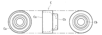
- the bearing holding member C is connected to the operating member 10 and holds the bearing B1 interposed between the operating member 10 and the pressure member 5, and as shown in FIG. It is composed of a cylindrical member having one end open, and has an open end Ca and a top Cb opposite to the open end Ca.
- the bearing B1 according to the present embodiment is attached inside the bearing holding member C on the side of the top portion Cb, and has a cylindrical portion extending from the enlarged diameter portion to the opening end portion Ca.
- a ball bearing is used as the bearing B1 according to the present embodiment, but other bearings such as a needle bearing may be used.
- the bearing holding member C is mounted such that the opening end portion Ca is fitted into the concave portion 4d formed in the clutch member (first clutch member 4a).
- the inner peripheral wall surface 4da of the concave portion 4d is fitted and fitted (fitted).
- the recess 4d is a circular recess having substantially the same size (strictly, a size slightly larger than the opening end Ca) following the outer shape of the opening end Ca, and the bearing holding member C is fitted into the recess 4d. By combining them, the power transmission device is positioned and centered.
- the bearing holding member C interlocks with the pressure member 5.
- the pressure contact force between the driving side clutch plate 6 and the driven side clutch plate 7 is released to turn off the clutch (shut off power transmission). ..
- the release spring m can hold the pressure member 5 in the non-actuated position, and is compressed as the interlocking member 9 moves to move the pressure member 5 from the non-actuated position toward the actuated position.
- the urging force can be applied while permitting the movement of the interlocking member 9 and the pressure member 5 until reaching.
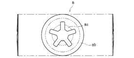
- the release spring m is a circular disc spring that can generate an urging force by the displacement of the central portion ma and the peripheral portion mb, and is shown in FIGS.
- the central portion ma is attached to the top portion Cb of the bearing holding member C
- the peripheral edge portion mb is attached to the pressure member 5.
- the pressure member 5 has a protruding portion 5d protruding in an annular shape, and the peripheral edge portion mb of the release spring m is locked to a ring-shaped member g (for example, a circlip or the like) attached to the protruding portion 5d. Then installed.
- the release spring m is attached across both the bearing holding member C and the pressure member 5, and applies an urging force to the pressure member 5 (an urging force in the direction indicated by symbol a2 in FIG. 20).
- the bearing holding member C can be applied with an urging force (an urging force in the direction indicated by reference numeral a1 in the figure) to transmit the urging force to the operating member 10.
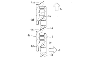
- the clutch spring 11 is composed of a coil spring interposed between the interlocking member 9 and the pressure member 5.
- the clutch spring 11 presses the pressure member 5 as the interlocking member 9 moves to drive the clutch plate 6 on the driving side and the clutch plate on the driven side.
- the pressure member 5 can be moved in a direction in which the pressure member 5 and 7 are brought into pressure contact with each other, and the pressing force of the pressure member 5 against the interlocking member 9 can be absorbed when the actuating member 10 is actuated.
- the clutch spring 11 is not compressed (does not bend) and moves integrally with the pressure member 5 until the driving side clutch plate 6 and the driven side clutch plate 7 reach the engaged state as described above.
- the interlocking member 9 is compressed in the process of moving, and the moving-side clutch plate 6 and the driven-side clutch 9 are allowed to move.
- the clutch plate 7 is configured to be able to apply a pressure contact force.
- the power transmission device moves the second clutch member 4b to drive the clutch plate on the drive side.
- 6 includes back torque transmitting cams (cam surfaces K1 and T1) capable of bringing the driven clutch plate 6 and the driven side clutch plate 7 into pressure contact with each other.
- the back torque transmitting cam has cam surfaces integrally formed on the mating surfaces of the first clutch member 4a and the second clutch member 4b (the mating surfaces when combined). (K1, T1).
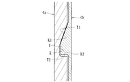
- a plurality of cam surfaces K1 are formed over the entire circumference on the inner diameter side of the flange surface 4ac formed on the first clutch member 4a (a mating surface with the second clutch member 4b). Is formed on one end surface of the groove K formed in a plurality of annular shapes along the peripheral edge of the first clutch member 4a. That is, the first clutch member 4a has a plurality of groove portions K formed in the circumferential direction thereof, and one end surface of each groove portion K is formed as a sloped surface to form the cam surface K1 of the back torque transmitting cam. Is doing.
- the other end surface of each groove K is a wall surface K2 extending in the axial direction of the first clutch member 4a.
- the cam surface T1 is a bottom surface of the second clutch member 4b (a mating surface with the first clutch member 4a) and is formed of a plurality of sloped surfaces over the entire circumference thereof. It is formed on one end surface of a plurality of protruding portions T formed in an annular shape along the bottom surface of the second clutch member 4b. That is, the second clutch member 4b is formed with a plurality of protrusions T in the circumferential direction thereof, and one end face of each protrusion T is formed into a sloped surface so that the cam surface T1 of the back torque transmitting cam. Is configured.
- the other end surface of each protrusion T is a wall surface T2 extending in the axial direction of the second clutch member 4b.
- a pressing portion 4bb is formed on the extension of the spline fitting portion 4ba, and when the second clutch member 4b moves to the right side in FIG. Of the drive-side clutch plate 6 and the driven-side clutch plate 7 mounted in a stacked state, the left-most driven-side clutch plate 7 in the figure is pressed in the same direction.
- the driving side clutch plate 6 and the driven side clutch plate 7 can be pressed against each other, and when the rotational force is input from the output shaft 3 (output member), The rotational force can be transmitted to the engine side to generate engine braking.
- the second clutch member 4b is moved in a direction approaching the interlocking member 9 (on the right side in FIG. 2) to bring the interlocking member 9 and the weight member 8 into contact with each other. It is configured to hold contact. That is, when the back torque transmitting cam operates to move the second clutch member 4b toward the right side in FIG. 2, the driving side clutch plate 6 and the driven side clutch plate 7 are brought into pressure contact with each other, and the pressure member 5 is moved. Since the pressing force is applied in the direction, the pressing force is transmitted to the interlocking member 9 via the clutch spring 11, and the contact between the interlocking member 9 and the weight member 8 is maintained.
- the weight member 8 is then moved to the inner diameter side position and the outer diameter side position as the clutch housing 2 rotates. Even if the interlocking member 9 cannot be made to follow the movement even if the interlocking member 9 and the weight are moved, the interlocking member 9 and the weight can be moved even when the back torque transmitting cam is operated. Since the contact with the member 8 can be maintained, the interlocking member 9 can stably follow the movement of the weight member 8.
- a plurality of cam surfaces K1 and T1 forming the back torque transmitting cam according to the present embodiment are formed along the annular shape of the driven side clutch plate 7 attached to the second clutch member 4b. That is, when the back torque transmitting cam operates, the cam surfaces K1 and T1 are formed along the projected shape (annular shape) of the driven side clutch plate 7 that is pressed by the pressing portion 4bb. As a result, the pressing portion 4bb can apply a substantially uniform pressing force to the driven side clutch plate 7 by the action of the back torque transmitting cam, and the driving side clutch plate 6 and the driven side clutch plate 7 can be more efficiently. 7 and 7 can be pressed together.
- the back torque transmitting cam (cam constituted by the cam surface K1 and cam surface T1) according to the present embodiment operates as the back torque limiter cam (cam constituted by the inclined surface 4ab and the inclined surface 5b). It is configured to operate before. That is, the clearance (gap dimension) between the cam surface K1 and the cam surface T1 is set to be smaller than the clearance (gap dimension) between the sloped surface 4ab and the sloped surface 5b, and before the operation of the back torque limiter cam.
- the back torque transmission cam can be operated.
- the back torque transmission cam (cam surface K1) is formed on the first clutch member 4a and the second clutch member 4b, and the rotational force transmitted to the second clutch member 4b is transferred.
- a plurality of convex portions F are integrally formed on the first clutch member 4a at equal intervals in the circumferential direction.
- the member 4b is integrally formed with a protrusion G extending inward.
- one convex portion F is sandwiched between two projecting portions G,
- the one side surface F1 of the portion F and the contact surface (first contact surface G1) of the one protruding portion G face each other, and the other side surface F2 of the convex portion F and the contact surface of the other protruding portion G (second contact surface)
- the contact surface G2) is configured to face each other.
- the one side surface F1 of the convex portion F formed on the first clutch member 4a and the first contact surface G1 of the one protruding portion G formed on the second clutch member 4b are the torque according to the present embodiment. It constitutes the transmission part. That is, when the pressure member 5 moves to the operating position and the driving side clutch plate 6 and the driven side clutch plate 7 are pressed into contact with each other to turn on the clutch (transmit the driving force), the back wall K2 of the groove portion K of the cam for back torque transmission and the wall surface K2. As shown in FIG. 15, one side surface F1 of the convex portion F and the first contact surface G1 of the protruding portion G are in contact with each other while maintaining the separated state (see FIG. 17) from the wall surface T2 of the protruding portion T, The rotational force of the second clutch member 4b can be received and transmitted to the first clutch member 4a.
- the other side surface F2 of the convex portion F formed on the first clutch member 4a and the second contact surface G2 of the other protruding portion G formed on the second clutch member 4b are the movement amounts according to the present embodiment. It constitutes the restriction unit. That is, when the rotational force is input to the first clutch member 4a via the output shaft 3, the first clutch member 4a and the second clutch member 4b rotate relative to each other, so that the groove K of the back torque transmitting cam is generated. The second clutch member 4b moves due to the cam action of the cam surface K1 of the above and the cam surface T1 of the protruding portion T (see FIG. 18). Then, when the amount of movement reaches the set value, as shown in FIG.
- the protrusion F is formed on the first clutch member 4a and the protrusion G is formed on the second clutch member 4b, but instead of this, the protrusion G is formed on the first clutch member 4a.
- the protrusion F may be formed on the second clutch member 4b.
- the one side surface F1 of the convex portion F formed on the second clutch member 4b and the first contact surface G1 of the one protruding portion G formed on the first clutch member 4a are the torque according to the present embodiment.
- the other side surface F2 of the convex portion F formed on the second clutch member 4b and the second contact surface G2 of the other protruding portion G formed on the first clutch member 4a constitute the transmission portion.
- a movement amount limiting unit according to the embodiment is configured.
- the operation of the back torque transmitting cam in this embodiment will be described.
- the weight member 8 is located at the inner diameter side position.
- the pressure member 5 is in the inoperative position.
- the second clutch member 4b moves to the right side in the figure by the action of the back torque transmitting cam,
- the driving side clutch plate 6 and the driven side clutch plate 7 are pressed against each other to transmit the rotational force to the engine side.
- the weight member 8 When the vehicle accelerates after starting and travels in the high speed range, the weight member 8 is at the outer diameter side position and the pressure member 5 is at the operating position because the rotation speed of the input gear 1 is high. ing.
- the action of the back torque transmitting cam causes the second clutch member 4b to move in the same figure. Moving to the right, the driving side clutch plate 6 and the driven side clutch plate 7 are pressed into contact with each other to transmit the rotational force to the engine side.
- the interlocking member 9 is interposed between the first clutch member 4a and the second clutch member 4b, and the interlocking member 9 moves to compress the pressure member 5 from the non-operating position to the operating position.
- the cushioning member 12 is provided that can apply the biasing force while allowing the interlocking member 9 and the pressure member 5 to move due to (the spring flexing).
- the cushioning member 12 is composed of a spring set to a load that is compressed before the clutch spring 11 starts to be compressed.
- the first clutch member 4a and the second clutch member 4b are It is housed and assembled in a housing recess 4c formed on a surface facing the surface (specifically, a surface of the first clutch member 4a facing the second clutch member 4b).
- the accommodating recess 4c is formed of a groove formed in an annular shape
- the cushioning member 12 is formed of a disc spring formed in an annular shape following the groove shape. ..
- the accommodating recess 4c is composed of a groove having a wall surface 4ca on the inner diameter side and a wall surface 4cb on the outer diameter side, and the buffer member 12 composed of an annular spring follows the groove shape. It is designed to fit in.
- the back torque transmitting cam according to the present embodiment is formed in a plurality of annular shapes on the surface where the first clutch member 4a and the second clutch member 4b face each other, and the accommodation recess 4c is As shown in FIG. 6, it is formed concentrically at a position adjacent to the back torque transmitting cam (in the present embodiment, the inner diameter side from the formation position of the back torque transmitting cam).
- the accommodation recess 4c is formed concentrically on the inner diameter side from the formation position of the back torque transmission cam, but is formed concentrically on the outer diameter side from the formation position of the back torque transmission cam. In this case, as shown in FIG.
- the cushioning member 12 has the drive-side clutch plate 6 and the drive-side clutch plate 6 and the driven-side clutch plate 7 stacked on the drive-side clutch plate 6 and the driven plate. You may comprise so that an urging
- the graph of FIG. Will be described with reference to a graph in which is the vertical axis.
- P1 is the pressing load of the interlocking member 9 at the time when the amount of flexure (compression amount) of the release spring m is maximum (when the maximum load of the release spring m is reached)
- P2 is the clutch spring.
- the release spring m moves until the movement amount of the interlocking member 9 reaches ⁇ .
- the clutch spring 11 is in the state of not bending while flexing (that is, the interlocking member 9 and the pressure member 5 move integrally), and when the moving amount of the interlocking member 9 reaches ⁇ , the pressing load (N) is changed from P1. Although it moves up to P2, the interlocking member 9 does not move and becomes a dead zone area.
- the clutch spring 11 in the process of movement of the interlocking member 9, is composed of a spring set to a load compressed before the compression starts (a spring whose set load is set to P3). Since the cushioning member 12 is provided, as shown in FIG. 22, from when the movement amount of the interlocking member 9 reaches ⁇ to when the cushioning member 12 starts to be compressed (begins to bend) and the pressing load reaches P2. The compression will continue.
- the moving amount of the interlocking member 9 is ⁇ in the process of moving the interlocking member 9 as the engine speed increases and the weight member 8 moves from the inner diameter side position to the outer diameter side position. Then, from the time when the pressing load (N) reaches P3, the cushioning member 12 is compressed, and thereafter, the movement amount of the interlocking member 9 reaches ⁇ and the pressing load (N) becomes P2. It can be seen that the clutch spring 11 starts to bend (compression starts).
- the pressing load (N) becomes the set load of the release spring m
- the release spring m starts to bend (compression starts)
- the movement amount of the interlocking member reaches ⁇ .
- the release spring m reaches the maximum load and the pressing load (N) is set by the clutch spring 11 (P2).
- the clutch spring 11 starts to bend (compression starts).
- the clutch spring 11 is continuously compressed (continuously bent) by the movement of the interlocking member 9 until the maximum load (upper limit of the operating load) is reached.
- the buffer member 12 is continuously compressed (flexed) in the process of the pressing load increasing from P3 to P2, and the interlocking member 9 is allowed to move. Therefore, the conventional dead zone can be reduced, and the weight member 8 and the interlocking member 9 can be smoothly and continuously moved. Therefore, it is possible to suppress the shock when the clutch is engaged and suppress the sudden feeling when the power is transmitted.
- the cushioning member 12 is configured such that the pressing load (N) is continuously compressed (continues to bend) between P3 and P2, but as shown in FIG.
- the movement amount of the interlocking member 9 becomes ⁇ and the cushioning member 12 starts to be compressed (begins to bend) when the pressing load (N) reaches P3, and the pressing load (N) becomes P4 lower than P2.
- the cushioning member 12 may be set to be continuously compressed (continuously bent) up to the time point. Even in this case, since the dead zone of the related art can be reduced as compared with the related art, the weight member 8 and the interlocking member 9 can be smoothly and continuously moved, and the shock at the time of clutch engagement can be suppressed to reduce power. It is possible to suppress the sudden feeling during transmission.
- the interlocking member 9 moves and the pressure member 5 compresses in the process of moving from the non-actuated position to the actuated position. Since the buffer member 12 that can apply the biasing force while allowing the movement of the interlocking member 9 and the pressure member 5 is provided, the space obtained by disposing the first clutch member 4a and the second clutch member 4b is effectively used. In addition, it is possible to suppress the sudden feeling during power transmission and improve the operability.
- the cushioning member 12 since the cushioning member 12 according to the present embodiment is composed of a spring set to a load that is compressed before the clutch spring 11 starts to be compressed, it is possible to more reliably suppress the sudden feeling during power transmission. In particular, by arbitrarily setting the set load and the operating load of the cushioning member 12, it is possible to set various feelings (starting feeling) at the time of power transmission according to the form of the vehicle to which the shock absorbing member 12 is applied.
- the cushioning member 12 according to the present embodiment is housed in the housing recess 4c formed on the surface where the first clutch member 4a and the second clutch member 4b face each other, the buffer member 12 is second with respect to the first clutch member 4a. When the clutch member 4b moves, it is possible to prevent the cushioning member 12 from being caught and misaligned.
- the accommodation recess 4c according to the present embodiment is formed on the surface of the first clutch member 4a that faces the second clutch member 4b, but on the surface of the second clutch member 4b that faces the first clutch member 4a. It may be formed.
- the accommodating recess 4c includes a groove formed in an annular shape
- the cushioning member 12 includes a spring formed in an annular shape following the groove shape.
- the generated urging force can be applied to the second clutch member 4b and the like substantially uniformly, and the urging force can be applied stably.
- the back torque transmitting cam according to the present embodiment is formed in a plurality of annular shapes on the surface where the first clutch member 4a and the second clutch member 4b face each other, and the accommodating recess 4c has the back torque transmitting cam. Since it is formed concentrically at a position adjacent to, the movement of the second clutch member 4b by the back torque transmitting cam and the application of the urging force by the buffer member 12 can be reliably and stably performed.
- the bearing holding member C is made of a cylindrical member whose one end is open, and the opening end Ca is fitted into the recess 4d formed in the clutch member (first clutch member 4a) and attached. Since the bearing holding member C is attached (mounted in the spigot state), the bearing holding member C can be easily assembled, and the bearing holding member C can be stably operated during the gear shift operation.
- a release spring m capable of applying a biasing force to the pressure member 5 while allowing the movement of the interlocking member 9 and the pressure member 5 until the engagement state before the driving side clutch plate 6 and the driven side clutch plate 7 are brought into pressure contact is reached.
- the release spring m is attached across both the bearing holding member C and the pressure member 5, and applies a biasing force to the pressure member 5 and a biasing force to the bearing holding member C. Since the urging force can be transmitted to the actuating member 10, the release spring m can also serve as a spring that prevents play of the gear shift operating means, and the number of parts can be reduced.
- the release spring m is a circular disc spring that can generate an urging force by the displacement of the central portion ma and the peripheral edge portion mb, and the central portion ma is attached to the bearing holding member C, and Since the peripheral edge portion mb is attached to the pressure member 5, the biasing force of the release spring m can be stably applied to both the bearing holding member C and the pressure member 5.
- the clutch member according to the present embodiment includes a first clutch member 4a connected to the output shaft 3 (output member), a second clutch member 4b to which the driven side clutch plate 7 is attached, and an output shaft 3 (output When a rotational force is input to the first clutch member 4a via the member), a back torque transmitting cam capable of moving the second clutch member 4b to bring the driving side clutch plate 6 and the driven side clutch plate 7 into pressure contact with each other.
- a back torque transmitting cam capable of moving the second clutch member 4b to bring the driving side clutch plate 6 and the driven side clutch plate 7 into pressure contact with each other.
- the concave portion 4d is formed in the first clutch member 4a, it is possible to prevent the bearing holding member C from hindering the movement of the second clutch member 4b by the back torque transmitting cam. And the movement of the second clutch member 4b by the back torque transmitting cam can be smoothly performed.
- the back torque transmitting cam moves the second clutch member 4b in the direction closer to the interlocking member 9 to maintain the contact between the interlocking member 9 and the weight member 8. Since the driving side clutch plate 6 and the driven side clutch plate 7 are brought into pressure contact with each other, the rotational force on the wheel side can be transmitted to the engine side to generate the engine brake, and the weight when the engine brake is generated is obtained. The operation by the member 8 can be stably performed.
- the back torque transmitting cam according to the present embodiment is constituted by the cam surfaces (K1, T1) formed integrally with each of the first clutch member 4a and the second clutch member 4b, and the cam surface (K1, Since T1) is formed on the mating surfaces of the first clutch member 4a and the second clutch member 4b, respectively, the back torque transmitting cam can reliably and smoothly move the second clutch member 2b.
- the inclined surface 4aa formed on the first clutch member 4a and the inclined surface 5a formed on the pressure member 5 are configured to face each other, and the rotational force input to the input gear 1 (input member) is applied to the output shaft 3 Since the pressure contact assist cam for increasing the pressure contact force between the driving side clutch plate 6 and the driven side clutch plate 7 when it is ready to be transmitted to the (output member) is provided, In addition to the pressure contact force associated with the movement, the pressure contact force by the pressure contact assist cam can be applied, and the drive side clutch plate 6 and the driven side clutch plate 7 can be pressed into contact with each other more smoothly and reliably.
- the inclined surface 4ab formed on the first clutch member 4a and the inclined surface 5b formed on the pressure member 5 are configured to face each other, and the rotation of the output shaft 3 (output member) causes the rotation of the input gear 1 (input member).
- the clutch member (the first clutch member 4a) and the pressure member 5 rotate relative to each other at a speed higher than the rotational speed of (4), the back force that can release the pressure contact force between the driving side clutch plate 6 and the driven side clutch plate 7. Since the torque limiter cam is provided, it is possible to prevent excessive power from being transmitted to the engine side via the input gear 1 when the weight member 8 is at the outer diameter side position, and the back torque limiter is provided. Since the back torque transmission cam is activated before the operation cam is activated, the operation by the back torque transmission cam can be reliably performed.
- the second clutch member 4b when the rotational force is input to the first clutch member 4a via the output shaft 3 (output member), the second clutch member 4b is moved to move the driving side clutch plate 6 and the driven member.
- first clutch member 4a and the second clutch member 4b are respectively provided with the movement amount limiting portions for limiting the movement amount of the second clutch member 4b by the back torque transmitting cam, the back torque transmitting cam is used.
- the second clutch member 4b can be moved within the set range.
- the convex portion F is formed on either one of the first clutch member 4a and the second clutch member 4b, and the torque transmission portion abuts on one side surface F1 of the convex portion F and the one side surface F1 and rotates.
- the second contact surface G2 includes a first contact surface G1 capable of receiving a force, and the movement amount limiting portion contacts the other side surface F2 of the convex portion F and the other side surface F2 to limit the movement amount. Therefore, the convex portion F can be made to perform the functions of the torque transmitting portion and the movement amount limiting portion.
- the present invention is not limited to these.
- the weight member 8 is movably disposed on the housing portion 2a of the clutch housing 2. You may apply to what was done.
- This power transmission device has a first clutch member 4a, a second clutch member 4b, and a back torque transmission cam, as in the above embodiment, and a cushioning member between the first clutch member 4a and the second clutch member 4b. 12 are interposed.
- FIG. 25 shows an embodiment in which the buffer member 12 is attached to the surface of the first clutch member 4a facing the second clutch member 4b, and in FIG. 26, the drive side clutch of the first clutch member 4a is shown. It shows an embodiment in which a cushioning member 12 that applies a biasing force is attached to a portion (disc pack) where the plate 6 and the driven side clutch plate 7 are laminated.
- the bearing holding member C′ is movable by the actuating member 10′, and the release spring m′ is a coil spring mounted over both the bearing holding member C′ and the pressure member 5. It is said that.
- a cushioning member 12' made of a wave spring is arranged in the accommodation recess 4c. Good.
- a wave spring is made of a C-shaped member having a notch 12'a in a part of an annular shape, and is formed into a wave shape (wave shape) in the thickness direction t. It can be elastically generated and is interposed between the first clutch member 4a and the second clutch member 4b, and the interlocking member 9 moves to compress the pressure member 5 in the process of moving from the non-actuated position to the actuated position. As a result, the biasing force can be applied while allowing the interlocking member 9 and the pressure member 5 to move.
- the bearing holding member C has a plurality of communication holes Cc (three in the present embodiment) formed in the side wall thereof, and the bearing holding member C is provided via the oil flow path r.
- the oil supplied into C can be discharged to the outside.
- the operating member 10′′ is locked to the roller bearing B1 of the bearing holding member C, and is moved in the left-right direction in FIG. It can be moved to and from the position.
- the bearing holding member C is formed of a cylindrical member having one end opened, and the opening end Ca is fitted into the recess 4d formed in the clutch member (first clutch member 4a) and attached.
- a bearing holding member having another shape may be used, and a mounting structure different from a form (so-called spigot) that fits into a recess formed in the clutch member may be used.
- the power transmission device of the present invention can be applied to various multi-disc clutch power transmission devices such as automobiles, automobiles, three-wheel or four-wheel buggies, and general-purpose machines, in addition to motorcycles.
- the clutch member is a first clutch member connected to the output member, a second clutch member to which the driven side clutch plate is attached, and a second clutch when the rotational force is input to the first clutch member via the output member.
- a back torque transmitting cam capable of moving the member to bring the driving side clutch plate and the driven side clutch plate into pressure contact is provided, and the interlocking member moves between the first clutch member and the second clutch member. If the power transmission device is provided with a buffer member that can apply a biasing force while allowing the movement of the interlocking member and the pressure member by compressing the pressure member in the process of moving from the non-operating position to the operating position, the external shape is The present invention can also be applied to different ones or those to which other functions are added.
Landscapes
- Engineering & Computer Science (AREA)
- General Engineering & Computer Science (AREA)
- Mechanical Engineering (AREA)
- Chemical & Material Sciences (AREA)
- Combustion & Propulsion (AREA)
- Transportation (AREA)
- Mechanical Operated Clutches (AREA)
- One-Way And Automatic Clutches, And Combinations Of Different Clutches (AREA)
Priority Applications (5)
| Application Number | Priority Date | Filing Date | Title |
|---|---|---|---|
| CN201980079116.XA CN113167336B (zh) | 2018-12-05 | 2019-12-04 | 动力传递装置 |
| EP19893997.7A EP3892880A4 (en) | 2018-12-05 | 2019-12-04 | ENERGY TRANSMISSION DEVICE |
| CN202211163254.6A CN115574011B (zh) | 2018-12-05 | 2019-12-04 | 动力传递装置 |
| US17/336,387 US11415190B2 (en) | 2018-12-05 | 2021-06-02 | Power transmission device |
| US17/861,228 US11603892B2 (en) | 2018-12-05 | 2022-07-10 | Power transmission device |
Applications Claiming Priority (2)
| Application Number | Priority Date | Filing Date | Title |
|---|---|---|---|
| JP2018227994A JP7209520B2 (ja) | 2018-12-05 | 2018-12-05 | 動力伝達装置 |
| JP2018-227994 | 2018-12-05 |
Related Child Applications (1)
| Application Number | Title | Priority Date | Filing Date |
|---|---|---|---|
| US17/336,387 Continuation US11415190B2 (en) | 2018-12-05 | 2021-06-02 | Power transmission device |
Publications (1)
| Publication Number | Publication Date |
|---|---|
| WO2020116506A1 true WO2020116506A1 (ja) | 2020-06-11 |
Family
ID=70974712
Family Applications (1)
| Application Number | Title | Priority Date | Filing Date |
|---|---|---|---|
| PCT/JP2019/047407 Ceased WO2020116506A1 (ja) | 2018-12-05 | 2019-12-04 | 動力伝達装置 |
Country Status (5)
| Country | Link |
|---|---|
| US (2) | US11415190B2 (enExample) |
| EP (1) | EP3892880A4 (enExample) |
| JP (1) | JP7209520B2 (enExample) |
| CN (2) | CN115574011B (enExample) |
| WO (1) | WO2020116506A1 (enExample) |
Cited By (1)
| Publication number | Priority date | Publication date | Assignee | Title |
|---|---|---|---|---|
| JP7651054B1 (ja) * | 2024-11-18 | 2025-03-25 | 株式会社エフ・シー・シー | クラッチ装置 |
Families Citing this family (3)
| Publication number | Priority date | Publication date | Assignee | Title |
|---|---|---|---|---|
| JP7209520B2 (ja) | 2018-12-05 | 2023-01-20 | 株式会社エフ・シー・シー | 動力伝達装置 |
| CN115427703B (zh) * | 2020-04-13 | 2025-04-08 | 株式会社F.C.C. | 动力传递装置 |
| CN114379353A (zh) * | 2020-10-19 | 2022-04-22 | 舍弗勒技术股份两合公司 | 车辆用动力系统及车辆 |
Citations (7)
| Publication number | Priority date | Publication date | Assignee | Title |
|---|---|---|---|---|
| JPS54140051A (en) * | 1978-04-24 | 1979-10-30 | Yamaha Motor Co Ltd | Centrifugal clutch |
| JPS6252228A (ja) * | 1985-08-31 | 1987-03-06 | Daihatsu Motor Co Ltd | 遠心クラツチ |
| WO2013183588A1 (ja) * | 2012-06-04 | 2013-12-12 | 株式会社エフ・シ-・シ- | 動力伝達装置 |
| WO2016143551A1 (ja) * | 2015-03-09 | 2016-09-15 | 株式会社エクセディ | クラッチ装置 |
| JP2017155884A (ja) | 2016-03-03 | 2017-09-07 | 株式会社エフ・シー・シー | 動力伝達装置 |
| JP2017155883A (ja) * | 2016-03-03 | 2017-09-07 | 株式会社エフ・シー・シー | 動力伝達装置 |
| WO2018116638A1 (ja) * | 2016-12-20 | 2018-06-28 | 株式会社エクセディ | 動力伝達装置 |
Family Cites Families (29)
| Publication number | Priority date | Publication date | Assignee | Title |
|---|---|---|---|---|
| GB909693A (en) * | 1959-09-16 | 1962-10-31 | Daimler Benz Ag | Improvements in clutches |
| EP0402956A1 (en) * | 1986-04-25 | 1990-12-19 | Ricardo Group Plc | Friction devices |
| US5638932A (en) * | 1994-05-17 | 1997-06-17 | Exedy Corporation | Dry multi-disk clutch |
| EP0724934B1 (en) * | 1995-01-31 | 2000-07-12 | Hitachi Koki Co., Ltd. | Power screwdriver and clutch mechanism used therein |
| JP3547849B2 (ja) * | 1995-05-19 | 2004-07-28 | 本田技研工業株式会社 | 遠心クラッチ |
| KR100343956B1 (ko) * | 2000-04-04 | 2002-07-20 | 현대자동차주식회사 | 수동변속기용 클러치 |
| US7014026B2 (en) * | 2001-06-07 | 2006-03-21 | Drussel Wilfley Design, L.L.C. | Manual/automatic pressure control mechanism for centrifugal clutch |
| US7140480B2 (en) * | 2001-06-07 | 2006-11-28 | Drussel Wilfley Design, Llc | Centrifugal clutch and cover mount assembly therefor |
| JP2005201433A (ja) * | 2003-12-15 | 2005-07-28 | Sanden Corp | 動力伝達装置 |
| JP2008039192A (ja) * | 2004-01-14 | 2008-02-21 | F C C:Kk | 動力伝達装置 |
| JP4252026B2 (ja) * | 2004-11-09 | 2009-04-08 | 株式会社エフ・シー・シー | 動力伝達装置の製造方法 |
| US20060237205A1 (en) * | 2005-04-21 | 2006-10-26 | Eastway Fair Company Limited | Mode selector mechanism for an impact driver |
| JP2009030792A (ja) * | 2007-06-29 | 2009-02-12 | Yamaha Motor Co Ltd | 遠心クラッチ及びそれを備えた車両 |
| JP2009197990A (ja) * | 2008-02-25 | 2009-09-03 | Yamaha Motor Co Ltd | 遠心クラッチを備えた自動二輪車 |
| JP2009197991A (ja) * | 2008-02-25 | 2009-09-03 | Yamaha Motor Co Ltd | 摩擦クラッチ |
| JP2010286000A (ja) * | 2009-06-09 | 2010-12-24 | F C C:Kk | 動力伝達装置 |
| JP5324345B2 (ja) * | 2009-07-06 | 2013-10-23 | 株式会社エフ・シー・シー | 動力伝達装置 |
| JP5171779B2 (ja) * | 2009-09-30 | 2013-03-27 | 本田技研工業株式会社 | 多板クラッチ装置 |
| JP5592829B2 (ja) * | 2011-03-31 | 2014-09-17 | 株式会社クボタ | 農作業機の変速伝動装置 |
| KR101282697B1 (ko) * | 2011-05-19 | 2013-07-05 | 현대자동차주식회사 | 자동변속기의 변속충격 저감장치 |
| JP5995439B2 (ja) * | 2011-12-28 | 2016-09-21 | 株式会社エフ・シー・シー | 動力伝達装置 |
| DE102013220265A1 (de) * | 2012-10-17 | 2014-04-17 | Schaeffler Technologies Gmbh & Co. Kg | Reibkupplung für ein Kraftfahrzeug und entsprechendes Kraftfahrzeug |
| JP2014209017A (ja) * | 2013-03-25 | 2014-11-06 | 株式会社ジェイテクト | 駆動力伝達装置、及び駆動力伝達装置の制御装置 |
| JP6295690B2 (ja) * | 2014-02-04 | 2018-03-20 | スズキ株式会社 | バックトルクリミッターを有するクラッチ |
| WO2016088860A1 (ja) * | 2014-12-04 | 2016-06-09 | 株式会社エフ・シー・シー | 動力伝達装置 |
| DE102015204441A1 (de) * | 2015-03-12 | 2016-09-15 | Schaeffler Technologies AG & Co. KG | Nachstelleinrichtung sowie Kupplungsdeckel für eine Reibungskupplung |
| JP2016176585A (ja) * | 2015-03-23 | 2016-10-06 | コニカミノルタ株式会社 | トルクリミッタ装置及びギヤユニット |
| CN206054657U (zh) * | 2016-08-31 | 2017-03-29 | 立马车业集团有限公司 | 电机自适应动力装置 |
| JP7209520B2 (ja) | 2018-12-05 | 2023-01-20 | 株式会社エフ・シー・シー | 動力伝達装置 |
-
2018
- 2018-12-05 JP JP2018227994A patent/JP7209520B2/ja active Active
-
2019
- 2019-12-04 WO PCT/JP2019/047407 patent/WO2020116506A1/ja not_active Ceased
- 2019-12-04 CN CN202211163254.6A patent/CN115574011B/zh active Active
- 2019-12-04 CN CN201980079116.XA patent/CN113167336B/zh active Active
- 2019-12-04 EP EP19893997.7A patent/EP3892880A4/en active Pending
-
2021
- 2021-06-02 US US17/336,387 patent/US11415190B2/en active Active
-
2022
- 2022-07-10 US US17/861,228 patent/US11603892B2/en active Active
Patent Citations (7)
| Publication number | Priority date | Publication date | Assignee | Title |
|---|---|---|---|---|
| JPS54140051A (en) * | 1978-04-24 | 1979-10-30 | Yamaha Motor Co Ltd | Centrifugal clutch |
| JPS6252228A (ja) * | 1985-08-31 | 1987-03-06 | Daihatsu Motor Co Ltd | 遠心クラツチ |
| WO2013183588A1 (ja) * | 2012-06-04 | 2013-12-12 | 株式会社エフ・シ-・シ- | 動力伝達装置 |
| WO2016143551A1 (ja) * | 2015-03-09 | 2016-09-15 | 株式会社エクセディ | クラッチ装置 |
| JP2017155884A (ja) | 2016-03-03 | 2017-09-07 | 株式会社エフ・シー・シー | 動力伝達装置 |
| JP2017155883A (ja) * | 2016-03-03 | 2017-09-07 | 株式会社エフ・シー・シー | 動力伝達装置 |
| WO2018116638A1 (ja) * | 2016-12-20 | 2018-06-28 | 株式会社エクセディ | 動力伝達装置 |
Non-Patent Citations (1)
| Title |
|---|
| See also references of EP3892880A4 |
Cited By (1)
| Publication number | Priority date | Publication date | Assignee | Title |
|---|---|---|---|---|
| JP7651054B1 (ja) * | 2024-11-18 | 2025-03-25 | 株式会社エフ・シー・シー | クラッチ装置 |
Also Published As
| Publication number | Publication date |
|---|---|
| CN115574011B (zh) | 2025-05-09 |
| US20210285509A1 (en) | 2021-09-16 |
| EP3892880A1 (en) | 2021-10-13 |
| CN115574011A (zh) | 2023-01-06 |
| JP7209520B2 (ja) | 2023-01-20 |
| JP2020090987A (ja) | 2020-06-11 |
| US11415190B2 (en) | 2022-08-16 |
| US11603892B2 (en) | 2023-03-14 |
| CN113167336B (zh) | 2022-10-18 |
| US20220341475A1 (en) | 2022-10-27 |
| CN113167336A (zh) | 2021-07-23 |
| EP3892880A4 (en) | 2022-09-07 |
Similar Documents
| Publication | Publication Date | Title |
|---|---|---|
| JP7705519B2 (ja) | 動力伝達装置 | |
| JP7256323B2 (ja) | 動力伝達装置 | |
| WO2011093335A1 (ja) | 動力伝達装置 | |
| WO2013137413A1 (ja) | 動力伝達装置 | |
| WO2020116506A1 (ja) | 動力伝達装置 | |
| WO2019044951A1 (ja) | 動力伝達装置 | |
| JP7307253B2 (ja) | 動力伝達装置 | |
| JP7149827B2 (ja) | 動力伝達装置 | |
| JP7121647B2 (ja) | 動力伝達装置 | |
| JP7307252B2 (ja) | 動力伝達装置 |
Legal Events
| Date | Code | Title | Description |
|---|---|---|---|
| 121 | Ep: the epo has been informed by wipo that ep was designated in this application |
Ref document number: 19893997 Country of ref document: EP Kind code of ref document: A1 |
|
| NENP | Non-entry into the national phase |
Ref country code: DE |
|
| ENP | Entry into the national phase |
Ref document number: 2019893997 Country of ref document: EP Effective date: 20210705 |