JP7209520B2 - 動力伝達装置 - Google Patents
動力伝達装置 Download PDFInfo
- Publication number
- JP7209520B2 JP7209520B2 JP2018227994A JP2018227994A JP7209520B2 JP 7209520 B2 JP7209520 B2 JP 7209520B2 JP 2018227994 A JP2018227994 A JP 2018227994A JP 2018227994 A JP2018227994 A JP 2018227994A JP 7209520 B2 JP7209520 B2 JP 7209520B2
- Authority
- JP
- Japan
- Prior art keywords
- clutch
- driven
- power transmission
- clutch plate
- transmission device
- Prior art date
- Legal status (The legal status is an assumption and is not a legal conclusion. Google has not performed a legal analysis and makes no representation as to the accuracy of the status listed.)
- Active
Links
Images


Classifications
-
- F—MECHANICAL ENGINEERING; LIGHTING; HEATING; WEAPONS; BLASTING
- F16—ENGINEERING ELEMENTS AND UNITS; GENERAL MEASURES FOR PRODUCING AND MAINTAINING EFFECTIVE FUNCTIONING OF MACHINES OR INSTALLATIONS; THERMAL INSULATION IN GENERAL
- F16D—COUPLINGS FOR TRANSMITTING ROTATION; CLUTCHES; BRAKES
- F16D13/00—Friction clutches
- F16D13/58—Details
- F16D13/60—Clutching elements
-
- F—MECHANICAL ENGINEERING; LIGHTING; HEATING; WEAPONS; BLASTING
- F16—ENGINEERING ELEMENTS AND UNITS; GENERAL MEASURES FOR PRODUCING AND MAINTAINING EFFECTIVE FUNCTIONING OF MACHINES OR INSTALLATIONS; THERMAL INSULATION IN GENERAL
- F16D—COUPLINGS FOR TRANSMITTING ROTATION; CLUTCHES; BRAKES
- F16D13/00—Friction clutches
- F16D13/22—Friction clutches with axially-movable clutching members
- F16D13/38—Friction clutches with axially-movable clutching members with flat clutching surfaces, e.g. discs
- F16D13/52—Clutches with multiple lamellae ; Clutches in which three or more axially moveable members are fixed alternately to the shafts to be coupled and are pressed from one side towards an axially-located member
- F16D13/54—Clutches with multiple lamellae ; Clutches in which three or more axially moveable members are fixed alternately to the shafts to be coupled and are pressed from one side towards an axially-located member with means for increasing the effective force between the actuating sleeve or equivalent member and the pressure member
- F16D13/56—Clutches with multiple lamellae ; Clutches in which three or more axially moveable members are fixed alternately to the shafts to be coupled and are pressed from one side towards an axially-located member with means for increasing the effective force between the actuating sleeve or equivalent member and the pressure member in which the clutching pressure is produced by springs only
-
- B—PERFORMING OPERATIONS; TRANSPORTING
- B60—VEHICLES IN GENERAL
- B60K—ARRANGEMENT OR MOUNTING OF PROPULSION UNITS OR OF TRANSMISSIONS IN VEHICLES; ARRANGEMENT OR MOUNTING OF PLURAL DIVERSE PRIME-MOVERS IN VEHICLES; AUXILIARY DRIVES FOR VEHICLES; INSTRUMENTATION OR DASHBOARDS FOR VEHICLES; ARRANGEMENTS IN CONNECTION WITH COOLING, AIR INTAKE, GAS EXHAUST OR FUEL SUPPLY OF PROPULSION UNITS IN VEHICLES
- B60K17/00—Arrangement or mounting of transmissions in vehicles
- B60K17/02—Arrangement or mounting of transmissions in vehicles characterised by arrangement, location, or kind of clutch
-
- F—MECHANICAL ENGINEERING; LIGHTING; HEATING; WEAPONS; BLASTING
- F16—ENGINEERING ELEMENTS AND UNITS; GENERAL MEASURES FOR PRODUCING AND MAINTAINING EFFECTIVE FUNCTIONING OF MACHINES OR INSTALLATIONS; THERMAL INSULATION IN GENERAL
- F16D—COUPLINGS FOR TRANSMITTING ROTATION; CLUTCHES; BRAKES
- F16D13/00—Friction clutches
- F16D13/22—Friction clutches with axially-movable clutching members
- F16D13/38—Friction clutches with axially-movable clutching members with flat clutching surfaces, e.g. discs
- F16D13/52—Clutches with multiple lamellae ; Clutches in which three or more axially moveable members are fixed alternately to the shafts to be coupled and are pressed from one side towards an axially-located member
-
- F—MECHANICAL ENGINEERING; LIGHTING; HEATING; WEAPONS; BLASTING
- F16—ENGINEERING ELEMENTS AND UNITS; GENERAL MEASURES FOR PRODUCING AND MAINTAINING EFFECTIVE FUNCTIONING OF MACHINES OR INSTALLATIONS; THERMAL INSULATION IN GENERAL
- F16D—COUPLINGS FOR TRANSMITTING ROTATION; CLUTCHES; BRAKES
- F16D13/00—Friction clutches
- F16D13/58—Details
-
- F—MECHANICAL ENGINEERING; LIGHTING; HEATING; WEAPONS; BLASTING
- F16—ENGINEERING ELEMENTS AND UNITS; GENERAL MEASURES FOR PRODUCING AND MAINTAINING EFFECTIVE FUNCTIONING OF MACHINES OR INSTALLATIONS; THERMAL INSULATION IN GENERAL
- F16D—COUPLINGS FOR TRANSMITTING ROTATION; CLUTCHES; BRAKES
- F16D43/00—Automatic clutches
- F16D43/02—Automatic clutches actuated entirely mechanically
- F16D43/04—Automatic clutches actuated entirely mechanically controlled by angular speed
- F16D43/06—Automatic clutches actuated entirely mechanically controlled by angular speed with centrifugal masses actuating axially a movable pressure ring or the like
- F16D43/08—Automatic clutches actuated entirely mechanically controlled by angular speed with centrifugal masses actuating axially a movable pressure ring or the like the pressure ring actuating friction plates, cones or similar axially-movable friction surfaces
- F16D43/12—Automatic clutches actuated entirely mechanically controlled by angular speed with centrifugal masses actuating axially a movable pressure ring or the like the pressure ring actuating friction plates, cones or similar axially-movable friction surfaces the centrifugal masses acting on, or forming a part of, an actuating mechanism by which the pressure ring can also be actuated independently of the masses
-
- F—MECHANICAL ENGINEERING; LIGHTING; HEATING; WEAPONS; BLASTING
- F16—ENGINEERING ELEMENTS AND UNITS; GENERAL MEASURES FOR PRODUCING AND MAINTAINING EFFECTIVE FUNCTIONING OF MACHINES OR INSTALLATIONS; THERMAL INSULATION IN GENERAL
- F16D—COUPLINGS FOR TRANSMITTING ROTATION; CLUTCHES; BRAKES
- F16D43/00—Automatic clutches
- F16D43/02—Automatic clutches actuated entirely mechanically
- F16D43/20—Automatic clutches actuated entirely mechanically controlled by torque, e.g. overload-release clutches, slip-clutches with means by which torque varies the clutching pressure
- F16D43/202—Automatic clutches actuated entirely mechanically controlled by torque, e.g. overload-release clutches, slip-clutches with means by which torque varies the clutching pressure of the ratchet type
- F16D43/204—Automatic clutches actuated entirely mechanically controlled by torque, e.g. overload-release clutches, slip-clutches with means by which torque varies the clutching pressure of the ratchet type with intermediate balls or rollers
- F16D43/206—Automatic clutches actuated entirely mechanically controlled by torque, e.g. overload-release clutches, slip-clutches with means by which torque varies the clutching pressure of the ratchet type with intermediate balls or rollers moving axially between engagement and disengagement
-
- F—MECHANICAL ENGINEERING; LIGHTING; HEATING; WEAPONS; BLASTING
- F16—ENGINEERING ELEMENTS AND UNITS; GENERAL MEASURES FOR PRODUCING AND MAINTAINING EFFECTIVE FUNCTIONING OF MACHINES OR INSTALLATIONS; THERMAL INSULATION IN GENERAL
- F16D—COUPLINGS FOR TRANSMITTING ROTATION; CLUTCHES; BRAKES
- F16D67/00—Combinations of couplings and brakes; Combinations of clutches and brakes
- F16D67/02—Clutch-brake combinations
-
- F—MECHANICAL ENGINEERING; LIGHTING; HEATING; WEAPONS; BLASTING
- F16—ENGINEERING ELEMENTS AND UNITS; GENERAL MEASURES FOR PRODUCING AND MAINTAINING EFFECTIVE FUNCTIONING OF MACHINES OR INSTALLATIONS; THERMAL INSULATION IN GENERAL
- F16D—COUPLINGS FOR TRANSMITTING ROTATION; CLUTCHES; BRAKES
- F16D13/00—Friction clutches
- F16D13/22—Friction clutches with axially-movable clutching members
- F16D13/38—Friction clutches with axially-movable clutching members with flat clutching surfaces, e.g. discs
- F16D13/52—Clutches with multiple lamellae ; Clutches in which three or more axially moveable members are fixed alternately to the shafts to be coupled and are pressed from one side towards an axially-located member
- F16D13/54—Clutches with multiple lamellae ; Clutches in which three or more axially moveable members are fixed alternately to the shafts to be coupled and are pressed from one side towards an axially-located member with means for increasing the effective force between the actuating sleeve or equivalent member and the pressure member
- F16D13/56—Clutches with multiple lamellae ; Clutches in which three or more axially moveable members are fixed alternately to the shafts to be coupled and are pressed from one side towards an axially-located member with means for increasing the effective force between the actuating sleeve or equivalent member and the pressure member in which the clutching pressure is produced by springs only
- F16D2013/565—Clutches with multiple lamellae ; Clutches in which three or more axially moveable members are fixed alternately to the shafts to be coupled and are pressed from one side towards an axially-located member with means for increasing the effective force between the actuating sleeve or equivalent member and the pressure member in which the clutching pressure is produced by springs only with means for releasing the clutch pressure in case of back torque
Landscapes
- Engineering & Computer Science (AREA)
- General Engineering & Computer Science (AREA)
- Mechanical Engineering (AREA)
- Chemical & Material Sciences (AREA)
- Combustion & Propulsion (AREA)
- Transportation (AREA)
- Mechanical Operated Clutches (AREA)
- One-Way And Automatic Clutches, And Combinations Of Different Clutches (AREA)
Description
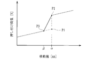
レリーズスプリングの圧縮が終了した時点の荷重(最大荷重)(図32のP1参照)とクラッチスプリングの圧縮が開始される時点の荷重(セット荷重)(同図のP2参照)との間に差が大きい場合、エンジンの回転数が上昇するのに伴って連動部材が移動してプレッシャ部材が非作動位置から作動位置に向かって移動する過程において、レリーズスプリングの圧縮が終了した後、クラッチスプリングの圧縮が開始されるまでの間に連動部材の移動が停止(同図の移動量αのまま停止)する不感帯領域が生じてしまう。
請求項6記載の発明は、車両のエンジンの駆動力で回転する入力部材と共に回転し、複数の駆動側クラッチ板が取り付けられたクラッチハウジングに収容されるクラッチ部材であって、前記クラッチハウジングの前記駆動側クラッチ板と交互に形成された複数の被動側クラッチ板が取り付けられるとともに、前記車両の車輪を回転させ得る出力部材と連結されたクラッチ部材と、前記クラッチハウジングの回転に伴う遠心力で内径側位置から外径側位置に移動可能とされたウェイト部材と、前記ウェイト部材が前記内径側位置から前記外径側位置に移動するのに伴って、前記駆動側クラッチ板および前記被動側クラッチ板を、圧接力が解放された非作動状態から、互いに圧接させて前記エンジンの駆動力を前記車輪に伝達可能な作動状態に切り替える連動部材とを有した動力伝達装置において、前記クラッチ部材は、前記出力部材と連結される第1クラッチ部材と、前記被動側クラッチ板が取り付けられる第2クラッチ部材と、前記出力部材を介して前記第1クラッチ部材に回転力が入力されると、前記第2クラッチ部材を移動させて前記駆動側クラッチ板と前記被動側クラッチ板とを圧接させ得るバックトルク伝達用カムとを有するとともに、前記連動部材が移動して前記駆動側クラッチ板および前記被動側クラッチ板が前記非作動状態から前記作動状態に切り替わる過程で圧縮することにより前記連動部材の移動を許容しつつ付勢力を付与し得る緩衝部材を具備し、さらに、前記バックトルク伝達用カムは、第1のカム面を有する第1部分と、前記第1部分と対向するように配置されたときに前記第1のカム面と対向する第2のカム面を有する第2部分と、を含み、前記第2部分は、前記出力部材の軸方向に延び、かつ、前記出力部材の径方向から見て前記緩衝部材と重なることを特徴とする。
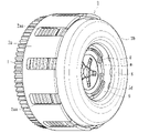
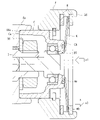
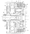
本実施形態に係る動力伝達装置は、二輪車等の車両に配設されて任意にエンジンの駆動力をミッションや駆動輪側へ伝達し又は遮断するためのもので、図1~12に示すように、車両のエンジンの駆動力で回転する入力ギア1(入力部材)が形成されたクラッチハウジング2と、クラッチ部材(第1クラッチ部材4a及び第2クラッチ部材4b)と、クラッチ部材(第1クラッチ部材4a及び第2クラッチ部材4b)の図2中右側に取り付けられたプレッシャ部材5と、複数の駆動側クラッチ板6及び複数の被動側クラッチ板7と、クラッチハウジング2内を径方向に移動(転動)可能な鋼球部材から成るウェイト部材8と、連動部材9と、手動操作又はアクチュエータ(不図示)により作動可能な作動部材10とから主に構成されている。なお、図中符号Sは、スプリングダンパを示しているとともに、符号B1はローラベアリング、及び符号B2、B3はスラストベアリングをそれぞれ示している。
エンジンが停止又はアイドリング状態のとき、入力ギア1にエンジンの駆動力が伝達されない或いは入力ギア1の回転数が低回転であるため、図2に示すように、ウェイト部材8が内径側位置とされるとともに、プレッシャ部材5が非作動位置とされている。このとき、出力シャフト3(出力部材)を介して第1クラッチ部材4aに回転力が入力されると、バックトルク伝達用カムの作用によって、第2クラッチ部材4bが同図中右側に移動し、駆動側クラッチ板6及び被動側クラッチ板7が圧接されてエンジン側に回転力を伝達させる。
先ず、本実施形態の如く緩衝部材12を具備していない場合の作用について、図32のグラフ(連動部材9の移動量(mm)を横軸、連動部材9に対して生じる押し付け荷重(N)を縦軸としたグラフ)を用いて説明する。なお、図32のグラフ中、P1はレリーズスプリングmの撓み量(圧縮量)が最大となった時点(レリーズスプリングmの最大荷重に達した時点)の連動部材9の押し付け荷重、P2はクラッチスプリング11が撓み始める時点(クラッチスプリング11のセット荷重に達した時点)の連動部材9の押し付け荷重、図22、23のグラフ中P3は、緩衝部材12が撓み始める時点(緩衝部材12のセット荷重に達した時点)の連動部材9の押し付け荷重となっている。
2 クラッチハウジング
2a 筐体部
2b カバー部
3 出力シャフト(出力部材)
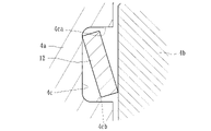
4a 第1クラッチ部材
4aa 勾配面(圧接アシスト用カム)
4ab 勾配面(バックトルクリミッタ用カム)
4ac フランジ面
4ad 挿通孔
4b 第2クラッチ部材
4ba スプライン嵌合部
4bb 押圧部
4c 収容凹部
4d 凹部
4da 内周壁面
5 プレッシャ部材
5a 勾配面(圧接アシスト用カム)
5b 勾配面(バックトルクリミッタ用カム)
5c フランジ面
6 駆動側クラッチ板
7 被動側クラッチ板
8 ウェイト部材
9 連動部材
10 作動部材
11 クラッチスプリング
12 緩衝部材(皿バネ)
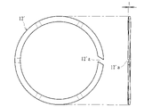
12’ 緩衝部材(ウェーブスプリング)
12’a 切欠き部
C ベアリング保持部材
Ca 開口端部
Cb 頂部
Cc 連通孔
K 溝部
K1 カム面
K2 壁面
T 突出部
T1 カム面
T2 壁面
F 凸部
G 突出部
G1 第1当接面
G2 第2当接面
m レリーズスプリング
r オイル流路
Claims (6)
- 車両のエンジンの駆動力で回転する入力部材と共に回転し、複数の駆動側クラッチ板が取り付けられたクラッチハウジングに収容されるクラッチ部材であって、
前記クラッチハウジングの前記駆動側クラッチ板と交互に形成された複数の被動側クラッチ板が取り付けられるとともに、前記車両の車輪を回転させ得る出力部材と連結されたクラッチ部材と、
前記駆動側クラッチ板と前記被動側クラッチ板とを圧接させて前記エンジンの駆動力を前記車輪に伝達可能な状態とする作動位置と、前記駆動側クラッチ板と前記被動側クラッチ板との圧接力を解放させて前記エンジンの駆動力が前記車輪に伝達されるのを遮断し得る非作動位置との間で移動可能なプレッシャ部材と、
前記クラッチハウジングの回転に伴う遠心力で内径側位置から外径側位置に移動可能とされたウェイト部材と、
前記ウェイト部材が前記内径側位置から前記外径側位置に移動するのに伴って、前記プレッシャ部材を前記非作動位置から前記作動位置に移動させ得る連動部材と、
前記プレッシャ部材を前記非作動位置に保持し得るとともに、前記連動部材が移動して前記プレッシャ部材が前記非作動位置から前記作動位置に向かって移動するのに伴って圧縮されるレリーズスプリングと、
前記駆動側クラッチ板及び前記被動側クラッチ板とが圧接された状態に達した後、前記連動部材が移動する過程で圧縮されるクラッチスプリングと、
を有した動力伝達装置において、
前記クラッチ部材は、
前記出力部材と連結される第1クラッチ部材と、
前記被動側クラッチ板が取り付けられる第2クラッチ部材と、
前記出力部材を介して前記第1クラッチ部材に回転力が入力されると、前記第2クラッチ部材を移動させて前記駆動側クラッチ板と前記被動側クラッチ板とを圧接させ得るバックトルク伝達用カムと、
を有するとともに、前記第1クラッチ部材と前記第2クラッチ部材との間に介在され、前記連動部材が移動して前記プレッシャ部材が前記非作動位置から前記作動位置に向かう過程で圧縮することにより前記連動部材及び前記プレッシャ部材の移動を許容しつつ付勢力を付与し得る緩衝部材を具備したことを特徴とする動力伝達装置。 - 前記緩衝部材は、前記クラッチスプリングが圧縮開始する前に圧縮される荷重に設定されたスプリングから成ることを特徴とする請求項1記載の動力伝達装置。
- 前記緩衝部材は、前記第1クラッチ部材及び第2クラッチ部材が対峙する面に形成された収容凹部に収容されたことを特徴とする請求項1又は請求項2記載の動力伝達装置。
- 前記収容凹部は、円環状に形成された溝から成るとともに、前記緩衝部材は、前記溝の形状に倣って円環状に形成されたスプリングから成ることを特徴とする請求項3記載の動力伝達装置。
- 前記バックトルク伝達用カムは、前記第1クラッチ部材及び前記第2クラッチ部材が対峙する面において円環状に複数形成されるとともに、前記収容凹部は、前記バックトルク伝達用カムと隣接した位置に同心円状に形成されたことを特徴とする請求項4記載の動力伝達装置。
- 車両のエンジンの駆動力で回転する入力部材と共に回転し、複数の駆動側クラッチ板が取り付けられたクラッチハウジングに収容されるクラッチ部材であって、
前記クラッチハウジングの前記駆動側クラッチ板と交互に形成された複数の被動側クラッチ板が取り付けられるとともに、前記車両の車輪を回転させ得る出力部材と連結されたクラッチ部材と、
前記クラッチハウジングの回転に伴う遠心力で内径側位置から外径側位置に移動可能とされたウェイト部材と、
前記ウェイト部材が前記内径側位置から前記外径側位置に移動するのに伴って、前記駆動側クラッチ板および前記被動側クラッチ板を、圧接力が解放された非作動状態から、互いに圧接させて前記エンジンの駆動力を前記車輪に伝達可能な作動状態に切り替える連動部材と、
を有した動力伝達装置において、
前記クラッチ部材は、
前記出力部材と連結される第1クラッチ部材と、
前記被動側クラッチ板が取り付けられる第2クラッチ部材と、
前記出力部材を介して前記第1クラッチ部材に回転力が入力されると、前記第2クラッチ部材を移動させて前記駆動側クラッチ板と前記被動側クラッチ板とを圧接させ得るバックトルク伝達用カムと、
を有するとともに、前記連動部材が移動して前記駆動側クラッチ板および前記被動側クラッチ板が前記非作動状態から前記作動状態に切り替わる過程で圧縮することにより前記連動部材の移動を許容しつつ付勢力を付与し得る緩衝部材を具備し、さらに、
前記バックトルク伝達用カムは、第1のカム面を有する第1部分と、前記第1部分と対向するように配置されたときに前記第1のカム面と対向する第2のカム面を有する第2部分と、を含み、
前記第2部分は、前記出力部材の軸方向に延び、かつ、前記出力部材の径方向から見て前記緩衝部材と重なることを特徴とする動力伝達装置。
Priority Applications (8)
| Application Number | Priority Date | Filing Date | Title |
|---|---|---|---|
| JP2018227994A JP7209520B2 (ja) | 2018-12-05 | 2018-12-05 | 動力伝達装置 |
| PCT/JP2019/047407 WO2020116506A1 (ja) | 2018-12-05 | 2019-12-04 | 動力伝達装置 |
| CN202211163254.6A CN115574011B (zh) | 2018-12-05 | 2019-12-04 | 动力传递装置 |
| CN201980079116.XA CN113167336B (zh) | 2018-12-05 | 2019-12-04 | 动力传递装置 |
| EP19893997.7A EP3892880A4 (en) | 2018-12-05 | 2019-12-04 | POWER TRANSMISSION DEVICE |
| US17/336,387 US11415190B2 (en) | 2018-12-05 | 2021-06-02 | Power transmission device |
| US17/861,228 US11603892B2 (en) | 2018-12-05 | 2022-07-10 | Power transmission device |
| JP2022159460A JP7307252B2 (ja) | 2018-12-05 | 2022-10-03 | 動力伝達装置 |
Applications Claiming Priority (1)
| Application Number | Priority Date | Filing Date | Title |
|---|---|---|---|
| JP2018227994A JP7209520B2 (ja) | 2018-12-05 | 2018-12-05 | 動力伝達装置 |
Related Child Applications (1)
| Application Number | Title | Priority Date | Filing Date |
|---|---|---|---|
| JP2022159460A Division JP7307252B2 (ja) | 2018-12-05 | 2022-10-03 | 動力伝達装置 |
Publications (3)
| Publication Number | Publication Date |
|---|---|
| JP2020090987A JP2020090987A (ja) | 2020-06-11 |
| JP2020090987A5 JP2020090987A5 (ja) | 2022-07-21 |
| JP7209520B2 true JP7209520B2 (ja) | 2023-01-20 |
Family
ID=70974712
Family Applications (1)
| Application Number | Title | Priority Date | Filing Date |
|---|---|---|---|
| JP2018227994A Active JP7209520B2 (ja) | 2018-12-05 | 2018-12-05 | 動力伝達装置 |
Country Status (5)
| Country | Link |
|---|---|
| US (2) | US11415190B2 (ja) |
| EP (1) | EP3892880A4 (ja) |
| JP (1) | JP7209520B2 (ja) |
| CN (2) | CN113167336B (ja) |
| WO (1) | WO2020116506A1 (ja) |
Families Citing this family (4)
| Publication number | Priority date | Publication date | Assignee | Title |
|---|---|---|---|---|
| JP7209520B2 (ja) | 2018-12-05 | 2023-01-20 | 株式会社エフ・シー・シー | 動力伝達装置 |
| EP4137713A4 (en) * | 2020-04-13 | 2024-05-08 | Kabushiki Kaisha F.C.C. | POWER TRANSMISSION DEVICE |
| CN114379353A (zh) * | 2020-10-19 | 2022-04-22 | 舍弗勒技术股份两合公司 | 车辆用动力系统及车辆 |
| JP7651054B1 (ja) * | 2024-11-18 | 2025-03-25 | 株式会社エフ・シー・シー | クラッチ装置 |
Citations (4)
| Publication number | Priority date | Publication date | Assignee | Title |
|---|---|---|---|---|
| WO2013183588A1 (ja) | 2012-06-04 | 2013-12-12 | 株式会社エフ・シ-・シ- | 動力伝達装置 |
| WO2016143551A1 (ja) | 2015-03-09 | 2016-09-15 | 株式会社エクセディ | クラッチ装置 |
| JP2017155883A (ja) | 2016-03-03 | 2017-09-07 | 株式会社エフ・シー・シー | 動力伝達装置 |
| WO2018116638A1 (ja) | 2016-12-20 | 2018-06-28 | 株式会社エクセディ | 動力伝達装置 |
Family Cites Families (32)
| Publication number | Priority date | Publication date | Assignee | Title |
|---|---|---|---|---|
| GB909693A (en) * | 1959-09-16 | 1962-10-31 | Daimler Benz Ag | Improvements in clutches |
| JPS54140051A (en) * | 1978-04-24 | 1979-10-30 | Yamaha Motor Co Ltd | Centrifugal clutch |
| JPH0648024B2 (ja) * | 1985-08-31 | 1994-06-22 | ダイハツ工業株式会社 | 遠心クラツチ |
| EP0402956A1 (en) * | 1986-04-25 | 1990-12-19 | Ricardo Group Plc | Friction devices |
| US5638932A (en) * | 1994-05-17 | 1997-06-17 | Exedy Corporation | Dry multi-disk clutch |
| DE69609208T2 (de) * | 1995-01-31 | 2000-11-23 | Hitachi Koki Co., Ltd. | Kraftangetriebener Schraubenzieher und Kupplungsmechanismus dafür |
| JP3547849B2 (ja) * | 1995-05-19 | 2004-07-28 | 本田技研工業株式会社 | 遠心クラッチ |
| KR100343956B1 (ko) * | 2000-04-04 | 2002-07-20 | 현대자동차주식회사 | 수동변속기용 클러치 |
| US7014026B2 (en) * | 2001-06-07 | 2006-03-21 | Drussel Wilfley Design, L.L.C. | Manual/automatic pressure control mechanism for centrifugal clutch |
| US7140480B2 (en) * | 2001-06-07 | 2006-11-28 | Drussel Wilfley Design, Llc | Centrifugal clutch and cover mount assembly therefor |
| JP2005201433A (ja) * | 2003-12-15 | 2005-07-28 | Sanden Corp | 動力伝達装置 |
| JP2008039192A (ja) * | 2004-01-14 | 2008-02-21 | F C C:Kk | 動力伝達装置 |
| JP4252026B2 (ja) * | 2004-11-09 | 2009-04-08 | 株式会社エフ・シー・シー | 動力伝達装置の製造方法 |
| US20060237205A1 (en) * | 2005-04-21 | 2006-10-26 | Eastway Fair Company Limited | Mode selector mechanism for an impact driver |
| JP2009030792A (ja) * | 2007-06-29 | 2009-02-12 | Yamaha Motor Co Ltd | 遠心クラッチ及びそれを備えた車両 |
| JP2009197991A (ja) * | 2008-02-25 | 2009-09-03 | Yamaha Motor Co Ltd | 摩擦クラッチ |
| JP2009197990A (ja) * | 2008-02-25 | 2009-09-03 | Yamaha Motor Co Ltd | 遠心クラッチを備えた自動二輪車 |
| JP2010286000A (ja) * | 2009-06-09 | 2010-12-24 | F C C:Kk | 動力伝達装置 |
| JP5324345B2 (ja) * | 2009-07-06 | 2013-10-23 | 株式会社エフ・シー・シー | 動力伝達装置 |
| JP5171779B2 (ja) * | 2009-09-30 | 2013-03-27 | 本田技研工業株式会社 | 多板クラッチ装置 |
| JP5592829B2 (ja) * | 2011-03-31 | 2014-09-17 | 株式会社クボタ | 農作業機の変速伝動装置 |
| KR101282697B1 (ko) * | 2011-05-19 | 2013-07-05 | 현대자동차주식회사 | 자동변속기의 변속충격 저감장치 |
| JP5995439B2 (ja) * | 2011-12-28 | 2016-09-21 | 株式会社エフ・シー・シー | 動力伝達装置 |
| DE102013220265A1 (de) * | 2012-10-17 | 2014-04-17 | Schaeffler Technologies Gmbh & Co. Kg | Reibkupplung für ein Kraftfahrzeug und entsprechendes Kraftfahrzeug |
| JP2014209017A (ja) * | 2013-03-25 | 2014-11-06 | 株式会社ジェイテクト | 駆動力伝達装置、及び駆動力伝達装置の制御装置 |
| JP6295690B2 (ja) * | 2014-02-04 | 2018-03-20 | スズキ株式会社 | バックトルクリミッターを有するクラッチ |
| JP6535346B2 (ja) * | 2014-12-04 | 2019-06-26 | 株式会社エフ・シー・シー | 動力伝達装置 |
| DE102015204441A1 (de) * | 2015-03-12 | 2016-09-15 | Schaeffler Technologies AG & Co. KG | Nachstelleinrichtung sowie Kupplungsdeckel für eine Reibungskupplung |
| JP2016176585A (ja) * | 2015-03-23 | 2016-10-06 | コニカミノルタ株式会社 | トルクリミッタ装置及びギヤユニット |
| JP6655430B2 (ja) | 2016-03-03 | 2020-02-26 | 株式会社エフ・シー・シー | 動力伝達装置 |
| CN206054657U (zh) * | 2016-08-31 | 2017-03-29 | 立马车业集团有限公司 | 电机自适应动力装置 |
| JP7209520B2 (ja) | 2018-12-05 | 2023-01-20 | 株式会社エフ・シー・シー | 動力伝達装置 |
-
2018
- 2018-12-05 JP JP2018227994A patent/JP7209520B2/ja active Active
-
2019
- 2019-12-04 CN CN201980079116.XA patent/CN113167336B/zh active Active
- 2019-12-04 EP EP19893997.7A patent/EP3892880A4/en active Pending
- 2019-12-04 WO PCT/JP2019/047407 patent/WO2020116506A1/ja not_active Ceased
- 2019-12-04 CN CN202211163254.6A patent/CN115574011B/zh active Active
-
2021
- 2021-06-02 US US17/336,387 patent/US11415190B2/en active Active
-
2022
- 2022-07-10 US US17/861,228 patent/US11603892B2/en active Active
Patent Citations (4)
| Publication number | Priority date | Publication date | Assignee | Title |
|---|---|---|---|---|
| WO2013183588A1 (ja) | 2012-06-04 | 2013-12-12 | 株式会社エフ・シ-・シ- | 動力伝達装置 |
| WO2016143551A1 (ja) | 2015-03-09 | 2016-09-15 | 株式会社エクセディ | クラッチ装置 |
| JP2017155883A (ja) | 2016-03-03 | 2017-09-07 | 株式会社エフ・シー・シー | 動力伝達装置 |
| WO2018116638A1 (ja) | 2016-12-20 | 2018-06-28 | 株式会社エクセディ | 動力伝達装置 |
Also Published As
| Publication number | Publication date |
|---|---|
| EP3892880A1 (en) | 2021-10-13 |
| EP3892880A4 (en) | 2022-09-07 |
| WO2020116506A1 (ja) | 2020-06-11 |
| CN113167336A (zh) | 2021-07-23 |
| US11603892B2 (en) | 2023-03-14 |
| CN115574011A (zh) | 2023-01-06 |
| JP2020090987A (ja) | 2020-06-11 |
| CN113167336B (zh) | 2022-10-18 |
| US20210285509A1 (en) | 2021-09-16 |
| US20220341475A1 (en) | 2022-10-27 |
| US11415190B2 (en) | 2022-08-16 |
| CN115574011B (zh) | 2025-05-09 |
Similar Documents
| Publication | Publication Date | Title |
|---|---|---|
| JP7256323B2 (ja) | 動力伝達装置 | |
| JP7209521B2 (ja) | 動力伝達装置 | |
| JP7209520B2 (ja) | 動力伝達装置 | |
| JP6961427B2 (ja) | 動力伝達装置 | |
| WO2019044951A1 (ja) | 動力伝達装置 | |
| JP7307253B2 (ja) | 動力伝達装置 | |
| JP7149827B2 (ja) | 動力伝達装置 | |
| JP7121647B2 (ja) | 動力伝達装置 | |
| JP7307252B2 (ja) | 動力伝達装置 |
Legal Events
| Date | Code | Title | Description |
|---|---|---|---|
| A621 | Written request for application examination |
Free format text: JAPANESE INTERMEDIATE CODE: A621 Effective date: 20210910 |
|
| A521 | Request for written amendment filed |
Free format text: JAPANESE INTERMEDIATE CODE: A523 Effective date: 20220712 |
|
| A131 | Notification of reasons for refusal |
Free format text: JAPANESE INTERMEDIATE CODE: A131 Effective date: 20220805 |
|
| A521 | Request for written amendment filed |
Free format text: JAPANESE INTERMEDIATE CODE: A523 Effective date: 20221003 |
|
| TRDD | Decision of grant or rejection written | ||
| A01 | Written decision to grant a patent or to grant a registration (utility model) |
Free format text: JAPANESE INTERMEDIATE CODE: A01 Effective date: 20221223 |
|
| A61 | First payment of annual fees (during grant procedure) |
Free format text: JAPANESE INTERMEDIATE CODE: A61 Effective date: 20230110 |
|
| R150 | Certificate of patent or registration of utility model |
Ref document number: 7209520 Country of ref document: JP Free format text: JAPANESE INTERMEDIATE CODE: R150 |
|
| R250 | Receipt of annual fees |
Free format text: JAPANESE INTERMEDIATE CODE: R250 |