JP7209520B2 - power transmission device - Google Patents
power transmission device Download PDFInfo
- Publication number
- JP7209520B2 JP7209520B2 JP2018227994A JP2018227994A JP7209520B2 JP 7209520 B2 JP7209520 B2 JP 7209520B2 JP 2018227994 A JP2018227994 A JP 2018227994A JP 2018227994 A JP2018227994 A JP 2018227994A JP 7209520 B2 JP7209520 B2 JP 7209520B2
- Authority
- JP
- Japan
- Prior art keywords
- clutch
- driven
- power transmission
- clutch plate
- transmission device
- Prior art date
- Legal status (The legal status is an assumption and is not a legal conclusion. Google has not performed a legal analysis and makes no representation as to the accuracy of the status listed.)
- Active
Links
- 230000005540 biological transmission Effects 0.000 title claims description 143
- 238000000034 method Methods 0.000 claims description 15
- 230000002093 peripheral effect Effects 0.000 description 13
- 238000010586 diagram Methods 0.000 description 9
- 230000004308 accommodation Effects 0.000 description 6
- 230000006835 compression Effects 0.000 description 6
- 238000007906 compression Methods 0.000 description 6
- 230000013011 mating Effects 0.000 description 6
- 230000035939 shock Effects 0.000 description 4
- 238000005452 bending Methods 0.000 description 3
- 230000015572 biosynthetic process Effects 0.000 description 3
- 238000013459 approach Methods 0.000 description 2
- 230000000903 blocking effect Effects 0.000 description 2
- 238000004891 communication Methods 0.000 description 2
- 238000000926 separation method Methods 0.000 description 2
- 229910000831 Steel Inorganic materials 0.000 description 1
- 238000006073 displacement reaction Methods 0.000 description 1
- 238000003780 insertion Methods 0.000 description 1
- 230000037431 insertion Effects 0.000 description 1
- 230000002452 interceptive effect Effects 0.000 description 1
- 239000000463 material Substances 0.000 description 1
- 238000005096 rolling process Methods 0.000 description 1
- 239000010959 steel Substances 0.000 description 1
Images


Classifications
-
- F—MECHANICAL ENGINEERING; LIGHTING; HEATING; WEAPONS; BLASTING
- F16—ENGINEERING ELEMENTS AND UNITS; GENERAL MEASURES FOR PRODUCING AND MAINTAINING EFFECTIVE FUNCTIONING OF MACHINES OR INSTALLATIONS; THERMAL INSULATION IN GENERAL
- F16D—COUPLINGS FOR TRANSMITTING ROTATION; CLUTCHES; BRAKES
- F16D13/00—Friction clutches
- F16D13/58—Details
- F16D13/60—Clutching elements
-
- F—MECHANICAL ENGINEERING; LIGHTING; HEATING; WEAPONS; BLASTING
- F16—ENGINEERING ELEMENTS AND UNITS; GENERAL MEASURES FOR PRODUCING AND MAINTAINING EFFECTIVE FUNCTIONING OF MACHINES OR INSTALLATIONS; THERMAL INSULATION IN GENERAL
- F16D—COUPLINGS FOR TRANSMITTING ROTATION; CLUTCHES; BRAKES
- F16D13/00—Friction clutches
- F16D13/22—Friction clutches with axially-movable clutching members
- F16D13/38—Friction clutches with axially-movable clutching members with flat clutching surfaces, e.g. discs
- F16D13/52—Clutches with multiple lamellae ; Clutches in which three or more axially moveable members are fixed alternately to the shafts to be coupled and are pressed from one side towards an axially-located member
- F16D13/54—Clutches with multiple lamellae ; Clutches in which three or more axially moveable members are fixed alternately to the shafts to be coupled and are pressed from one side towards an axially-located member with means for increasing the effective force between the actuating sleeve or equivalent member and the pressure member
- F16D13/56—Clutches with multiple lamellae ; Clutches in which three or more axially moveable members are fixed alternately to the shafts to be coupled and are pressed from one side towards an axially-located member with means for increasing the effective force between the actuating sleeve or equivalent member and the pressure member in which the clutching pressure is produced by springs only
-
- B—PERFORMING OPERATIONS; TRANSPORTING
- B60—VEHICLES IN GENERAL
- B60K—ARRANGEMENT OR MOUNTING OF PROPULSION UNITS OR OF TRANSMISSIONS IN VEHICLES; ARRANGEMENT OR MOUNTING OF PLURAL DIVERSE PRIME-MOVERS IN VEHICLES; AUXILIARY DRIVES FOR VEHICLES; INSTRUMENTATION OR DASHBOARDS FOR VEHICLES; ARRANGEMENTS IN CONNECTION WITH COOLING, AIR INTAKE, GAS EXHAUST OR FUEL SUPPLY OF PROPULSION UNITS IN VEHICLES
- B60K17/00—Arrangement or mounting of transmissions in vehicles
- B60K17/02—Arrangement or mounting of transmissions in vehicles characterised by arrangement, location, or kind of clutch
-
- F—MECHANICAL ENGINEERING; LIGHTING; HEATING; WEAPONS; BLASTING
- F16—ENGINEERING ELEMENTS AND UNITS; GENERAL MEASURES FOR PRODUCING AND MAINTAINING EFFECTIVE FUNCTIONING OF MACHINES OR INSTALLATIONS; THERMAL INSULATION IN GENERAL
- F16D—COUPLINGS FOR TRANSMITTING ROTATION; CLUTCHES; BRAKES
- F16D13/00—Friction clutches
- F16D13/22—Friction clutches with axially-movable clutching members
- F16D13/38—Friction clutches with axially-movable clutching members with flat clutching surfaces, e.g. discs
- F16D13/52—Clutches with multiple lamellae ; Clutches in which three or more axially moveable members are fixed alternately to the shafts to be coupled and are pressed from one side towards an axially-located member
-
- F—MECHANICAL ENGINEERING; LIGHTING; HEATING; WEAPONS; BLASTING
- F16—ENGINEERING ELEMENTS AND UNITS; GENERAL MEASURES FOR PRODUCING AND MAINTAINING EFFECTIVE FUNCTIONING OF MACHINES OR INSTALLATIONS; THERMAL INSULATION IN GENERAL
- F16D—COUPLINGS FOR TRANSMITTING ROTATION; CLUTCHES; BRAKES
- F16D13/00—Friction clutches
- F16D13/58—Details
-
- F—MECHANICAL ENGINEERING; LIGHTING; HEATING; WEAPONS; BLASTING
- F16—ENGINEERING ELEMENTS AND UNITS; GENERAL MEASURES FOR PRODUCING AND MAINTAINING EFFECTIVE FUNCTIONING OF MACHINES OR INSTALLATIONS; THERMAL INSULATION IN GENERAL
- F16D—COUPLINGS FOR TRANSMITTING ROTATION; CLUTCHES; BRAKES
- F16D43/00—Automatic clutches
- F16D43/02—Automatic clutches actuated entirely mechanically
- F16D43/04—Automatic clutches actuated entirely mechanically controlled by angular speed
- F16D43/06—Automatic clutches actuated entirely mechanically controlled by angular speed with centrifugal masses actuating axially a movable pressure ring or the like
- F16D43/08—Automatic clutches actuated entirely mechanically controlled by angular speed with centrifugal masses actuating axially a movable pressure ring or the like the pressure ring actuating friction plates, cones or similar axially-movable friction surfaces
- F16D43/12—Automatic clutches actuated entirely mechanically controlled by angular speed with centrifugal masses actuating axially a movable pressure ring or the like the pressure ring actuating friction plates, cones or similar axially-movable friction surfaces the centrifugal masses acting on, or forming a part of, an actuating mechanism by which the pressure ring can also be actuated independently of the masses
-
- F—MECHANICAL ENGINEERING; LIGHTING; HEATING; WEAPONS; BLASTING
- F16—ENGINEERING ELEMENTS AND UNITS; GENERAL MEASURES FOR PRODUCING AND MAINTAINING EFFECTIVE FUNCTIONING OF MACHINES OR INSTALLATIONS; THERMAL INSULATION IN GENERAL
- F16D—COUPLINGS FOR TRANSMITTING ROTATION; CLUTCHES; BRAKES
- F16D43/00—Automatic clutches
- F16D43/02—Automatic clutches actuated entirely mechanically
- F16D43/20—Automatic clutches actuated entirely mechanically controlled by torque, e.g. overload-release clutches, slip-clutches with means by which torque varies the clutching pressure
- F16D43/202—Automatic clutches actuated entirely mechanically controlled by torque, e.g. overload-release clutches, slip-clutches with means by which torque varies the clutching pressure of the ratchet type
- F16D43/204—Automatic clutches actuated entirely mechanically controlled by torque, e.g. overload-release clutches, slip-clutches with means by which torque varies the clutching pressure of the ratchet type with intermediate balls or rollers
- F16D43/206—Automatic clutches actuated entirely mechanically controlled by torque, e.g. overload-release clutches, slip-clutches with means by which torque varies the clutching pressure of the ratchet type with intermediate balls or rollers moving axially between engagement and disengagement
-
- F—MECHANICAL ENGINEERING; LIGHTING; HEATING; WEAPONS; BLASTING
- F16—ENGINEERING ELEMENTS AND UNITS; GENERAL MEASURES FOR PRODUCING AND MAINTAINING EFFECTIVE FUNCTIONING OF MACHINES OR INSTALLATIONS; THERMAL INSULATION IN GENERAL
- F16D—COUPLINGS FOR TRANSMITTING ROTATION; CLUTCHES; BRAKES
- F16D67/00—Combinations of couplings and brakes; Combinations of clutches and brakes
- F16D67/02—Clutch-brake combinations
-
- F—MECHANICAL ENGINEERING; LIGHTING; HEATING; WEAPONS; BLASTING
- F16—ENGINEERING ELEMENTS AND UNITS; GENERAL MEASURES FOR PRODUCING AND MAINTAINING EFFECTIVE FUNCTIONING OF MACHINES OR INSTALLATIONS; THERMAL INSULATION IN GENERAL
- F16D—COUPLINGS FOR TRANSMITTING ROTATION; CLUTCHES; BRAKES
- F16D13/00—Friction clutches
- F16D13/22—Friction clutches with axially-movable clutching members
- F16D13/38—Friction clutches with axially-movable clutching members with flat clutching surfaces, e.g. discs
- F16D13/52—Clutches with multiple lamellae ; Clutches in which three or more axially moveable members are fixed alternately to the shafts to be coupled and are pressed from one side towards an axially-located member
- F16D13/54—Clutches with multiple lamellae ; Clutches in which three or more axially moveable members are fixed alternately to the shafts to be coupled and are pressed from one side towards an axially-located member with means for increasing the effective force between the actuating sleeve or equivalent member and the pressure member
- F16D13/56—Clutches with multiple lamellae ; Clutches in which three or more axially moveable members are fixed alternately to the shafts to be coupled and are pressed from one side towards an axially-located member with means for increasing the effective force between the actuating sleeve or equivalent member and the pressure member in which the clutching pressure is produced by springs only
- F16D2013/565—Clutches with multiple lamellae ; Clutches in which three or more axially moveable members are fixed alternately to the shafts to be coupled and are pressed from one side towards an axially-located member with means for increasing the effective force between the actuating sleeve or equivalent member and the pressure member in which the clutching pressure is produced by springs only with means for releasing the clutch pressure in case of back torque
Description
本発明は、任意に入力部材の回転力を出力部材に伝達させ又は遮断させ得る動力伝達装置に関するものである。
BACKGROUND OF THE
一般に自動二輪車が具備する動力伝達装置は、エンジンの駆動力をミッション及び駆動輪へ伝達又は遮断を任意に行わせるためのもので、エンジン側と連結された入力部材と、ミッション及び駆動輪側と連結された出力部材と、出力部材と連結されたクラッチ部材と、クラッチ部材に対して近接又は離間可能なプレッシャ部材とを有しており、プレッシャ部材をクラッチ部材に対して近接させることにより、駆動側クラッチ板と被動側クラッチ板とを圧接させて動力の伝達を行わせるとともに、プレッシャ部材をクラッチ部材に対して離間させることにより、駆動側クラッチ板と被動側クラッチ板との圧接力を解放させることにより当該動力の伝達を遮断するよう構成されている。 In general, a power transmission device provided in a motorcycle is for arbitrarily transmitting or interrupting the driving force of the engine to the transmission and the drive wheels. It has a coupled output member, a clutch member coupled with the output member, and a pressure member that can approach or separate from the clutch member. The side clutch plate and the driven side clutch plate are brought into pressure contact to transmit power, and the pressure member is separated from the clutch member to release the pressure contact force between the driving side clutch plate and the driven side clutch plate. By doing so, the transmission of the power is cut off.
従来の動力伝達装置として、例えば特許文献1で開示されているように、クラッチハウジングの回転に伴う遠心力で当該溝部の内径側位置から外径側位置に移動することにより駆動側クラッチ板と被動側クラッチ板とを圧接させ得るウェイト部材を具備したものが提案されている。かかる従来の動力伝達装置によれば、エンジンの駆動に伴ってクラッチハウジングが回転することにより、ウェイト部材に遠心力を付与させることができ、駆動側クラッチ板と被動側クラッチ板とを圧接させてエンジンの駆動力を車輪に伝達させることができる。
As a conventional power transmission device, for example, as disclosed in
さらに、従来の動力伝達装置は、連動部材が移動してプレッシャ部材が非作動位置から作動位置に向かって移動するのに伴って圧縮され、駆動側クラッチ板及び被動側クラッチ板が圧接される前の締結状態に達するまで連動部材及びプレッシャ部材の移動を許容しつつ付勢力を付与し得るレリーズスプリングと、駆動側クラッチ板及び被動側クラッチ板が締結状態に達した後、連動部材が移動する過程で圧縮され、連動部材の移動を許容しつつ駆動側クラッチ板及び被動側クラッチ板の圧接力を付与し得るクラッチスプリングとを具備していた。 Furthermore, in the conventional power transmission device, as the interlocking member moves and the pressure member moves from the non-operating position toward the operating position, the pressure member is compressed, and before the drive-side clutch plate and the driven-side clutch plate are pressed against each other, the pressure member is compressed. A release spring that can apply a biasing force while allowing the movement of the interlocking member and the pressure member until reaching the engaged state of , and a process in which the interlocking member moves after the drive-side clutch plate and the driven-side clutch plate reach the engaged state. and a clutch spring which is compressed by , and which can apply pressure contact force to the driving side clutch plate and the driven side clutch plate while allowing the movement of the interlocking member.
しかしながら、上記従来の動力伝達装置においては、以下のような問題があった。
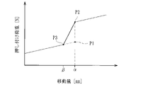
レリーズスプリングの圧縮が終了した時点の荷重(最大荷重)(図32のP1参照)とクラッチスプリングの圧縮が開始される時点の荷重(セット荷重)(同図のP2参照)との間に差が大きい場合、エンジンの回転数が上昇するのに伴って連動部材が移動してプレッシャ部材が非作動位置から作動位置に向かって移動する過程において、レリーズスプリングの圧縮が終了した後、クラッチスプリングの圧縮が開始されるまでの間に連動部材の移動が停止(同図の移動量αのまま停止)する不感帯領域が生じてしまう。
However, the conventional power transmission device described above has the following problems.
There is a difference between the load (maximum load) when the release spring completes compression (see P1 in FIG. 32) and the load (set load) when the clutch spring starts to compress (see P2 in the same figure). If it is large, in the process in which the interlocking member moves as the engine speed increases and the pressure member moves from the non-operating position toward the operating position, the clutch spring is compressed after the release spring is compressed. A dead zone region is generated in which the movement of the interlocking member stops (stops at the movement amount α in the figure) until the start of .
そして、エンジンの回転数が更に上昇して連動部材に付与される押し付け荷重がクラッチスプリングのセット荷重に達する(同図のP2の時点)と、クラッチスプリングの圧縮が開始されるので、連動部材が再び移動し始めて不感帯領域が経過するのであるが、その不感帯領域が経過した後にクラッチ板が圧接して動力が伝達されるので、動力伝達時の唐突感があり操作性に影響を及ぼしてしまう虞があった。 Then, when the engine speed further increases and the pressing load applied to the interlocking member reaches the set load of the clutch spring (at point P2 in the figure), compression of the clutch spring starts, so that the interlocking member The movement starts again and the dead zone passes, but after the dead zone passes, the clutch plates are pressed against each other and the power is transmitted. was there.
一方、本出願人は、エンジンブレーキを良好に発生させるべくクラッチ部材を2つに分けて構成し、出力部材と連結される第1クラッチ部材と、被動側クラッチ板が取り付けられる第2クラッチ部材と、出力部材を介して第1クラッチ部材に回転力が入力されると、第2クラッチ部材を移動させて駆動側クラッチ板と被動側クラッチ板とを圧接させ得るバックトルク伝達用カムとを具備した動力伝達装置を検討しており、唐突感の抑制のための手段を配設するにあたり、このような第1クラッチ部材及び第2クラッチ部材の配設に伴って得られるスペースを有効利用することを鋭意検討するに至った。 On the other hand, the applicant of the present invention divides the clutch member into two so as to generate good engine braking. and a back torque transmission cam capable of moving the second clutch member to bring the driving side clutch plate and the driven side clutch plate into pressure contact when a rotational force is input to the first clutch member through the output member. We are studying a power transmission device, and in arranging means for suppressing the feeling of abruptness, it is desirable to effectively utilize the space obtained by arranging the first clutch member and the second clutch member. I have come to seriously consider it.
本発明は、このような事情に鑑みてなされたもので、第1クラッチ部材及び第2クラッチ部材の配設に伴って得られるスペースを有効活用しつつ動力伝達時の唐突感を抑制して操作性を向上させることができる動力伝達装置を提供することにある。 SUMMARY OF THE INVENTION The present invention has been made in view of such circumstances. To provide a power transmission device capable of improving performance.
請求項1記載の発明は、車両のエンジンの駆動力で回転する入力部材と共に回転し、複数の駆動側クラッチ板が取り付けられたクラッチハウジングに収容されるクラッチ部材であって、前記クラッチハウジングの前記駆動側クラッチ板と交互に形成された複数の被動側クラッチ板が取り付けられるとともに、前記車両の車輪を回転させ得る出力部材と連結されたクラッチ部材と、前記駆動側クラッチ板と前記被動側クラッチ板とを圧接させて前記エンジンの駆動力を前記車輪に伝達可能な状態とする作動位置と、前記駆動側クラッチ板と前記被動側クラッチ板との圧接力を解放させて前記エンジンの駆動力が前記車輪に伝達されるのを遮断し得る非作動位置との間で移動可能なプレッシャ部材と、前記クラッチハウジングの回転に伴う遠心力で内径側位置から外径側位置に移動可能とされたウェイト部材と、前記ウェイト部材が前記内径側位置から前記外径側位置に移動するのに伴って、前記プレッシャ部材を前記非作動位置から前記作動位置に移動させ得る連動部材と、前記プレッシャ部材を前記非作動位置に保持し得るとともに、前記連動部材が移動して前記プレッシャ部材が前記非作動位置から前記作動位置に向かって移動するのに伴って圧縮されるレリーズスプリングと、前記駆動側クラッチ板及び前記被動側クラッチ板とが圧接された状態に達した後、前記連動部材が移動する過程で圧縮されるクラッチスプリングとを有した動力伝達装置において、前記クラッチ部材は、前記出力部材と連結される第1クラッチ部材と、前記被動側クラッチ板が取り付けられる第2クラッチ部材と、前記出力部材を介して前記第1クラッチ部材に回転力が入力されると、前記第2クラッチ部材を移動させて前記駆動側クラッチ板と前記被動側クラッチ板とを圧接させ得るバックトルク伝達用カムとを有するとともに、前記第1クラッチ部材と前記第2クラッチ部材との間に介在され、前記連動部材が移動して前記プレッシャ部材が前記非作動位置から前記作動位置に向かう過程で圧縮することにより前記連動部材及び前記プレッシャ部材の移動を許容しつつ付勢力を付与し得る緩衝部材を具備したことを特徴とする。 According to a first aspect of the present invention, there is provided a clutch member that rotates together with an input member that rotates under the driving force of a vehicle engine and is housed in a clutch housing to which a plurality of drive-side clutch plates are attached, wherein the a clutch member having a driving clutch plate and a plurality of driven clutch plates alternately mounted thereon and connected to an output member capable of rotating a wheel of the vehicle; the driving clutch plate and the driven clutch plate; and a working position in which the driving force of the engine can be transmitted to the wheels, and a pressure contact force between the driving side clutch plate and the driven side clutch plate is released so that the driving force of the engine is transferred to the A pressure member movable between a non-operating position capable of blocking transmission to the wheels, and a weight member movable from an inner diameter side position to an outer diameter side position by centrifugal force accompanying rotation of the clutch housing. an interlocking member capable of moving the pressure member from the non-operating position to the operating position as the weight member moves from the inner diameter side position to the outer diameter side position; a release spring capable of being held at an operating position and compressed as the interlocking member moves and the pressure member moves from the non-operating position toward the operating position ; and a clutch spring that is compressed in the course of movement of the interlocking member after reaching a state in which the clutch plate on the driven side is in pressure contact, wherein the clutch member is connected to the output member. 1 clutch member, a second clutch member to which the driven-side clutch plate is attached, and when a rotational force is input to the first clutch member through the output member, the second clutch member is moved to move the driving clutch member. It has a back torque transmission cam capable of press-contacting the side clutch plate and the driven side clutch plate, and is interposed between the first clutch member and the second clutch member so that the interlocking member moves to move the It is characterized by comprising a cushioning member capable of applying an urging force while allowing movement of the interlocking member and the pressure member by compressing the pressure member in the process of moving from the non-operating position to the operating position.
請求項2記載の発明は、請求項1記載の動力伝達装置において、前記緩衝部材は、前記クラッチスプリングが圧縮開始する前に圧縮される荷重に設定されたスプリングから成る。 According to a second aspect of the invention, there is provided the power transmission device according to the first aspect, wherein the buffer member comprises a spring set to a load that is compressed before the clutch spring starts to compress.
請求項3記載の発明は、請求項1又は請求項2記載の動力伝達装置において、前記緩衝部材は、前記第1クラッチ部材及び第2クラッチ部材が対峙する面に形成された収容凹部に収容されたことを特徴とする。 According to a third aspect of the present invention, there is provided a power transmission device according to the first or second aspect, wherein the cushioning member is accommodated in an accommodation recess formed in the surfaces of the first clutch member and the second clutch member facing each other. characterized by
請求項4記載の発明は、請求項3記載の動力伝達装置において、前記収容凹部は、円環状に形成された溝から成るとともに、前記緩衝部材は、前記溝の形状に倣って円環状に形成されたスプリングから成ることを特徴とする。 According to a fourth aspect of the invention, there is provided the power transmission device according to the third aspect, wherein the accommodation recess is formed of a groove formed in an annular shape, and the cushioning member is formed in an annular shape following the shape of the groove. characterized in that it consists of an integrated spring.
請求項5記載の発明は、請求項4記載の動力伝達装置において、前記バックトルク伝達用カムは、前記第1クラッチ部材及び前記第2クラッチ部材が対峙する面において円環状に複数形成されるとともに、前記収容凹部は、前記バックトルク伝達用カムと隣接した位置に同心円状に形成されたことを特徴とする。
請求項6記載の発明は、車両のエンジンの駆動力で回転する入力部材と共に回転し、複数の駆動側クラッチ板が取り付けられたクラッチハウジングに収容されるクラッチ部材であって、前記クラッチハウジングの前記駆動側クラッチ板と交互に形成された複数の被動側クラッチ板が取り付けられるとともに、前記車両の車輪を回転させ得る出力部材と連結されたクラッチ部材と、前記クラッチハウジングの回転に伴う遠心力で内径側位置から外径側位置に移動可能とされたウェイト部材と、前記ウェイト部材が前記内径側位置から前記外径側位置に移動するのに伴って、前記駆動側クラッチ板および前記被動側クラッチ板を、圧接力が解放された非作動状態から、互いに圧接させて前記エンジンの駆動力を前記車輪に伝達可能な作動状態に切り替える連動部材とを有した動力伝達装置において、前記クラッチ部材は、前記出力部材と連結される第1クラッチ部材と、前記被動側クラッチ板が取り付けられる第2クラッチ部材と、前記出力部材を介して前記第1クラッチ部材に回転力が入力されると、前記第2クラッチ部材を移動させて前記駆動側クラッチ板と前記被動側クラッチ板とを圧接させ得るバックトルク伝達用カムとを有するとともに、前記連動部材が移動して前記駆動側クラッチ板および前記被動側クラッチ板が前記非作動状態から前記作動状態に切り替わる過程で圧縮することにより前記連動部材の移動を許容しつつ付勢力を付与し得る緩衝部材を具備し、さらに、前記バックトルク伝達用カムは、第1のカム面を有する第1部分と、前記第1部分と対向するように配置されたときに前記第1のカム面と対向する第2のカム面を有する第2部分と、を含み、前記第2部分は、前記出力部材の軸方向に延び、かつ、前記出力部材の径方向から見て前記緩衝部材と重なることを特徴とする。
According to a fifth aspect of the invention, there is provided a power transmission device according to the fourth aspect, wherein a plurality of the back torque transmission cams are annularly formed on the surfaces where the first clutch member and the second clutch member face each other. The housing recess is formed concentrically at a position adjacent to the back torque transmission cam.
According to a sixth aspect of the present invention, there is provided a clutch member that rotates together with an input member that rotates under the driving force of a vehicle engine and is accommodated in a clutch housing to which a plurality of drive-side clutch plates are attached, wherein the A plurality of driven-side clutch plates alternately formed with drive-side clutch plates are attached, and a clutch member connected to an output member capable of rotating the wheels of the vehicle and a centrifugal force caused by the rotation of the clutch housing generate an internal clutch. a weight member that is movable from a radial position to an outer diameter position; and the driving clutch plate and the driven clutch as the weight member moves from the inner diameter position to the outer diameter position. and an interlocking member that presses the plates against each other from a non-operating state in which the pressing force is released to an operating state in which the driving force of the engine can be transmitted to the wheels, wherein the clutch member comprises: A first clutch member connected to the output member, a second clutch member to which the driven-side clutch plate is attached, and when rotational force is input to the first clutch member through the output member, the second a back torque transmission cam capable of moving a clutch member to bring the driving side clutch plate and the driven side clutch plate into pressure contact with each other; is compressed in the process of switching from the non-operating state to the operating state to apply a biasing force while allowing the movement of the interlocking member; and a second portion having a second cam surface facing the first cam surface when arranged to face the first portion, the second The two portions are characterized in that they extend in the axial direction of the output member and overlap the cushioning member when viewed from the radial direction of the output member.
請求項1の発明によれば、第1クラッチ部材と第2クラッチ部材との間に介在され、連動部材が移動してプレッシャ部材が非作動位置から作動位置に向かう過程で圧縮することにより連動部材及びプレッシャ部材の移動を許容しつつ付勢力を付与し得る緩衝部材を具備したので、第1クラッチ部材及び第2クラッチ部材の配設に伴って得られるスペースを有効活用しつつ動力伝達時の唐突感を抑制して操作性を向上させることができる。 According to the first aspect of the invention, the interlocking member is interposed between the first clutch member and the second clutch member, and the interlocking member is compressed in the process of moving and moving the pressure member from the non-operating position to the operating position. In addition, since the cushioning member is provided which can apply the biasing force while allowing the movement of the pressure member, the space obtained by arranging the first clutch member and the second clutch member can be effectively utilized, and abruptness during power transmission can be prevented. It is possible to suppress the feeling and improve the operability.
請求項2の発明によれば、緩衝部材は、クラッチスプリングが圧縮開始する前に圧縮される荷重に設定されたスプリングから成るので、動力伝達時の唐突感をより確実に抑制することができる。 According to the second aspect of the invention, the shock absorbing member is composed of a spring set to a load that is compressed before the clutch spring starts to compress, so it is possible to more reliably suppress a feeling of abruptness during power transmission.
請求項3の発明によれば、緩衝部材は、第1クラッチ部材及び第2クラッチ部材が対峙する面に形成された収容凹部に収容されたので、第1クラッチ部材に対して第2クラッチ部材が移動する際、緩衝部材が巻き込まれて位置ずれが生じてしまうのを回避することができる。 According to the third aspect of the invention, the cushioning member is housed in the housing recess formed in the facing surfaces of the first clutch member and the second clutch member. When moving, it is possible to avoid the buffer member being caught in the cushioning member and resulting in positional deviation.
請求項4の発明によれば、収容凹部は、円環状に形成された溝から成るとともに、緩衝部材は、当該溝形状に倣って円環状に形成されたスプリングから成るので、緩衝部材で生じた付勢力を第2クラッチ部材等に対して略均一に付与させることができ、付勢力を安定して付与させることができる。 According to the fourth aspect of the invention, the accommodation recess is formed by a groove formed in an annular shape, and the cushioning member is formed by a spring formed in an annular shape following the shape of the groove. The biasing force can be applied substantially uniformly to the second clutch member and the like, and the biasing force can be applied stably.
請求項5の発明によれば、バックトルク伝達用カムは、第1クラッチ部材及び第2クラッチ部材が対峙する面において円環状に複数形成されるとともに、収容凹部は、当該バックトルク伝達用カムと隣接した位置に同心円状に形成されたので、バックトルク伝達用カムによる第2クラッチ部材の移動と、緩衝部材による付勢力の付与とを確実且つ安定して行わせることができる。 According to the fifth aspect of the present invention, the back torque transmission cams are formed in a plurality of annular shapes on the surfaces where the first clutch member and the second clutch member face each other, and the accommodating recess is provided with the back torque transmission cams. Since they are concentrically formed at adjacent positions, the movement of the second clutch member by the back torque transmission cam and the application of the biasing force by the buffer member can be reliably and stably performed.
以下、本発明の実施形態について図面を参照しながら具体的に説明する。
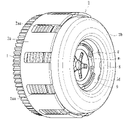
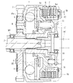
本実施形態に係る動力伝達装置は、二輪車等の車両に配設されて任意にエンジンの駆動力をミッションや駆動輪側へ伝達し又は遮断するためのもので、図1~12に示すように、車両のエンジンの駆動力で回転する入力ギア1(入力部材)が形成されたクラッチハウジング2と、クラッチ部材(第1クラッチ部材4a及び第2クラッチ部材4b)と、クラッチ部材(第1クラッチ部材4a及び第2クラッチ部材4b)の図2中右側に取り付けられたプレッシャ部材5と、複数の駆動側クラッチ板6及び複数の被動側クラッチ板7と、クラッチハウジング2内を径方向に移動(転動)可能な鋼球部材から成るウェイト部材8と、連動部材9と、手動操作又はアクチュエータ(不図示)により作動可能な作動部材10とから主に構成されている。なお、図中符号Sは、スプリングダンパを示しているとともに、符号B1はローラベアリング、及び符号B2、B3はスラストベアリングをそれぞれ示している。
Hereinafter, embodiments of the present invention will be specifically described with reference to the drawings.
A power transmission device according to the present embodiment is provided in a vehicle such as a two-wheeled vehicle to arbitrarily transmit or block the driving force of an engine to a transmission or driving wheels. , a
入力ギア1は、エンジンから伝達された駆動力(回転力)が入力されると出力シャフト3を中心として回転可能とされたもので、リベットR等によりクラッチハウジング2と連結されている。クラッチハウジング2は、図2中右端側が開口した円筒状部材から成るとともに入力ギア1と連結された筐体部2aと、該筐体部2aの開口を塞ぐように取り付けられたカバー部2bとを有して構成されており、エンジンの駆動力により入力ギア1の回転と共に回転し得るようになっている。
The
また、クラッチハウジング2における筐体部2aは、図4に示すように、周方向に亘って複数の切欠き2aaが形成されており、これら切欠き2aaに嵌合して複数の駆動側クラッチ板6が取り付けられている。かかる駆動側クラッチ板6のそれぞれは、略円環状に形成された板材から成るとともにクラッチハウジング2の回転と共に回転し、且つ、軸方向(図2中左右方向)に摺動し得るよう構成されている。
As shown in FIG. 4, the
さらに、クラッチハウジング2におけるカバー部2bは、図5に示すように、その底面において当該カバー部2bの径方向に延設された複数の溝部2baが形成されている。かかる溝部2baには、それぞれウェイト部材8が配設されており、クラッチハウジング2が停止した状態(エンジン停止又はアイドリング状態)及び低速で回転した状態では、当該ウェイト部材8が内径側位置(図2で示す位置)とされるとともに、クラッチハウジング2が高速で回転した状態では、当該ウェイト部材8が外径側位置となるよう設定されている。
Further, as shown in FIG. 5, the
クラッチ部材(第1クラッチ部材4a及び第2クラッチ部材4b)は、クラッチハウジング2の駆動側クラッチ板6と交互に形成された複数の被動側クラッチ板7が取り付けられるとともに、車両の車輪を回転させ得る出力シャフト3(出力部材)と連結されたものであり、第1クラッチ部材4aと第2クラッチ部材4bとの2つの部材を組み付けて構成されている。
The clutch members (the first
第1クラッチ部材4aは、図6に示すように、周縁部に亘ってフランジ面4acが形成された円板状部材から成るもので、その中央に形成された挿通孔4ad(図2、6参照)に出力シャフト3が挿通され、互いに形成されたギアが噛み合って回転方向に連結されるよう構成されている。かかる第1クラッチ部材4aには、図6、9、10に示すように、圧接アシスト用カムを構成する勾配面4aaと、バックトルクリミッタ用カムを構成する勾配面4abとが形成されている。
As shown in FIG. 6, the first
第2クラッチ部材4bは、図7に示すように、円環状部材から成るもので、外周面に形成されたスプライン嵌合部4ba(図2、7参照)に被動側クラッチ板7がスプライン嵌合にて取り付けられるよう構成されている。そして、クラッチ部材(第1クラッチ部材4a及び第2クラッチ部材4b)には、図9~11に示すように、プレッシャ部材5が組み付けられ、当該プレッシャ部材5のフランジ面5c(図2、8参照)と第1クラッチ部材4aのフランジ面4ac(図2、6参照)との間に複数の駆動側クラッチ板6及び被動側クラッチ板7が交互に積層状態にて取り付けられるようになっている。
As shown in FIG. 7, the second
プレッシャ部材5は、図8に示すように、周縁部に亘ってフランジ面5cが形成された円板状部材から成るもので、駆動側クラッチ板6と被動側クラッチ板7とを圧接させてエンジンの駆動力を車輪に伝達可能な状態とする作動位置と、当該駆動側クラッチ板6と被動側クラッチ板7との圧接力を解放させてエンジンの駆動力が車輪に伝達されるのを遮断し得る非作動位置(図2参照)との間で移動可能なものである。
As shown in FIG. 8, the
より具体的には、第2クラッチ部材4bに形成されたスプライン嵌合部4baは、図7、9、10に示すように、当該第2クラッチ部材4bの外周側面における略全周に亘って一体的に形成された凹凸形状にて構成されており、スプライン嵌合部4baを構成する凹溝に被動側クラッチ板7が嵌合することにより、被動側クラッチ板7の第2クラッチ部材4bに対する軸方向の移動を許容しつつ回転方向の移動が規制され、当該第2クラッチ部材4bと共に回転し得るよう構成されているのである。
More specifically, as shown in FIGS. 7, 9 and 10, the spline fitting portion 4ba formed on the second
かかる被動側クラッチ板7は、駆動側クラッチ板6と交互に積層形成されており、隣接する各クラッチ板6、7が圧接又は圧接力の解放が可能なようになっている。すなわち、両クラッチ板6、7は、第2クラッチ部材4bの軸方向への摺動が許容されており、プレッシャ部材5が図2中左側に移動してそのフランジ面5c及び第1クラッチ部材4aのフランジ面4acが近接すると、両クラッチ板6、7が圧接され、クラッチハウジング2の回転力が第2クラッチ部材4b及び第1クラッチ部材4aを介して出力シャフト3に伝達される状態となり、プレッシャ部材5が図2中右側に移動してそのフランジ面5c及び第1クラッチ部材4aのフランジ面4acが離間すると、両クラッチ板6、7の圧接力が解放して第1クラッチ部材4a及び第2クラッチ部材4bがクラッチハウジング2の回転に追従しなくなり、出力シャフト3への回転力の伝達がなされなくなるのである。
The driven-side
しかして、駆動側クラッチ板6と被動側クラッチ板7とが圧接された状態にて、クラッチハウジング2に入力された回転力(エンジンの駆動力)を出力シャフト3(出力部材)を介して車輪側に伝達するとともに、駆動側クラッチ板6と被動側クラッチ板7との圧接が解放された状態にて、クラッチハウジング2に入力された回転力(エンジンの駆動力)が出力シャフト3(出力部材)に伝達されるのを遮断し得るようになっている。
With the drive-side
さらに、本実施形態においては、図6、8、9、10に示すように、第1クラッチ部材4aには、勾配面4aa及び4abが形成されるとともに、プレッシャ部材5には、これら勾配面4aa及び4abと対峙する勾配面5a、5bが形成されている。すなわち、勾配面4aaと勾配面5aとが当接して圧接アシスト用カムを成すとともに、勾配面4abと勾配面5bとが当接してバックトルクリミッタ用カムを成しているのである。 Furthermore, in this embodiment, as shown in FIGS. and 4ab are formed. That is, the inclined surfaces 4aa and 5a are in contact with each other to form a press assist cam, and the inclined surfaces 4ab and 5b are in contact with each other to form a back torque limiter cam.
そして、エンジンの回転数が上がり、入力ギア1及びクラッチハウジング2に入力された回転力が、第1クラッチ部材4a及び第2クラッチ部材4bを介して出力シャフト3に伝達され得る状態(ウェイト部材8が外径側位置)となったときに、図13に示すように、プレッシャ部材5にはa方向の回転力が付与されるため、圧接アシスト用カムの作用により、当該プレッシャ部材5には同図中c方向への力が発生する。これにより、プレッシャ部材5は、そのフランジ面5cが第1クラッチ部材4aのフランジ面4acに対して更に近接する方向(図2中左側)に移動して、駆動側クラッチ板6と被動側クラッチ板7との圧接力を増加させるようになっている。
Then, the rotational speed of the engine increases, and the rotational force input to the
一方、車両が走行中、出力シャフト3の回転が入力ギア1及びクラッチハウジング2の回転数を上回って、図14中b方向のバックトルクが生じた際には、バックトルクリミッタ用カムの作用により、プレッシャ部材5を同図中d方向へ移動させて駆動側クラッチ板6と被動側クラッチ板7との圧接力を解放させるようになっている。これにより、バックトルクによる動力伝達装置や動力源(エンジン側)に対する不具合を回避することができる。
On the other hand, while the vehicle is running, when the rotation speed of the
ウェイト部材8は、クラッチハウジング2(本実施形態においてはカバー部2b)の径方向に延設された溝部2ba内に配設され、当該クラッチハウジング2の回転に伴う遠心力で当該溝部2baの内径側位置(図2参照)から外径側位置に移動することにより駆動側クラッチ板6と被動側クラッチ板7とを圧接させ得るものである。すなわち、溝部2baにおけるウェイト部材8の転動面(底面)は、内径側位置から外径側位置に向かって上り勾配とされており、クラッチハウジング2が停止した状態ではウェイト部材8をレリーズスプリングmの付勢力にて内径側位置に保持させるとともに、クラッチハウジング2が回転すると、ウェイト部材8に遠心力が付与されて上り勾配に沿って移動させ、当該クラッチハウジング2が所定の回転数に達することにより外径側位置まで移動させるようになっている。
The
連動部材9は、クラッチハウジング2(カバー部材2b)内に配設された円環状部材から成るもので、カバー部材2bの内周面に形成された溝部に嵌合して連結され、当該クラッチハウジング2と共に回転可能とされるとともに、図2中左右方向に移動可能とされている。かかる連動部材9は、ウェイト部材8が内径側位置から外径側位置に移動するのに伴って、レリーズスプリングmの付勢力に抗して図2中左側に移動し、プレッシャ部材5を押圧して非作動位置から作動位置に移動させ得るよう構成されている。
The interlocking
作動部材10は、手動又はアクチュエータで操作可能な部材(図2参照)から成り、駆動側クラッチ板6と被動側クラッチ板7との圧接力を解放させ得る方向(図2中右側)にプレッシャ部材5を移動させ得るものである。なお、作動部材10は、変速操作時、例えば車両が具備するクラッチペダルやクラッチレバー等に対する操作、或いはアクチュエータの作動により図2中右側に移動してベアリング保持部材Cを介してプレッシャ部材5と当接し、当該プレッシャ部材5を作動位置から非作動位置まで移動させることにより、駆動側クラッチ板6と被動側クラッチ板7との圧接力を解放してクラッチをオフ(動力の伝達を遮断)させ得るようになっている。
The actuating
ベアリング保持部材Cは、図2に示すように、作動部材10と連結されるとともに、当該作動部材10とプレッシャ部材5との間に介在するベアリングB1を保持するもので、図12に示すように、一端が開口した円筒状部材から成り、開口端部Caと、該開口端部Caとは反対面の頂部Cbとを有して構成されている。なお、本実施形態に係るベアリングB1は、ベアリング保持部材Cの内部における頂部Cb側に取り付けられ、拡径した部位から開口端部Caまで円筒状部位が延設されている。本実施形態に係るベアリングB1は、ボールベアリングが用いられているが、例えばニードルベアリング等、他のベアリングを用いるようにしてもよい。
As shown in FIG. 2, the bearing holding member C is connected to the operating
さらに、本実施形態に係るベアリング保持部材Cは、図2、20に示すように、その開口端部Caがクラッチ部材(第1クラッチ部材4a)に形成された凹部4dに嵌入して取り付けられており、凹部4dの内周壁面4daに対してインロー(はめ合い嵌合)して組み付けられている。また、凹部4dは、開口端部Caの外形に倣った略同一寸法(厳密には、開口端部Caより若干大きい寸法)の円形状の窪みから成り、当該凹部4dにベアリング保持部材Cを嵌合させることにより、動力伝達装置に対する位置決め及び芯出しがなされるようになっている。
Furthermore, as shown in FIGS. 2 and 20, the bearing holding member C according to the present embodiment is attached by fitting its open end Ca into the
しかして、変速操作時、例えば車両が具備するクラッチペダルやクラッチレバー等に対する操作、或いはアクチュエータの作動により作動部材10が図2中右側に移動すると、ベアリング保持部材Cが連動してプレッシャ部材5と当接し、当該プレッシャ部材5を作動位置から非作動位置まで移動させることにより、駆動側クラッチ板6と被動側クラッチ板7との圧接力を解放してクラッチをオフ(動力の伝達を遮断)させる。
Thus, when the operating
レリーズスプリングmは、プレッシャ部材5を非作動位置に保持し得るとともに、連動部材9が移動してプレッシャ部材5が非作動位置から作動位置に向かって移動するのに伴って圧縮され、駆動側クラッチ板6及び被動側クラッチ板7が圧接される前の締結状態(駆動側クラッチ板6と被動側クラッチ板7との離間距離がゼロとなり、且つ、圧接による動力伝達が行われる直前の状態)に達するまで連動部材9及びプレッシャ部材5の移動を許容しつつ付勢力を付与し得るものである。
The release spring m can hold the
さらに、本実施形態に係るレリーズスプリングmは、図21で示すように、中央部maと周縁部mbとの変位により付勢力を生じさせ得る円形状の皿バネから成り、図2、20に示すように、中央部maがベアリング保持部材Cの頂部Cbに取り付けられるとともに、周縁部mbがプレッシャ部材5に取り付けられている。なお、プレッシャ部材5は、円環状に突出した突出部5dを有しており、当該突出部5dに取り付けられたリング状部材g(例えばサークリップ等)にレリーズスプリングmの周縁部mbが係止して取り付けられている。これにより、本実施形態に係るレリーズスプリングmは、ベアリング保持部材C及びプレッシャ部材5の両部材に亘って取り付けられ、プレッシャ部材5に付勢力(図20中符号a2で示す向きの付勢力)を付与するとともに、ベアリング保持部材Cに付勢力(同図中符号a1で示す向きの付勢力)を付与して作動部材10に当該付勢力を伝達させ得るようになっている。
Further, the release spring m according to this embodiment is, as shown in FIG. , the central portion ma is attached to the top portion Cb of the bearing holding member C, and the peripheral edge portion mb is attached to the
クラッチスプリング11は、連動部材9とプレッシャ部材5との間に介装されたコイルスプリングから成り、当該連動部材9の移動に伴いプレッシャ部材5を押圧して駆動側クラッチ板6と被動側クラッチ板7とを圧接させる方向に当該プレッシャ部材5を移動させ得るとともに、作動部材10の作動時、当該プレッシャ部材5の連動部材9に対する押圧力を吸収し得るものである。
The
また、本実施形態に係るクラッチスプリング11は、駆動側クラッチ板6及び被動側クラッチ板7が上述の如き締結状態に達するまでは、圧縮されず(撓まず)にプレッシャ部材5と一体的に移動するとともに、駆動側クラッチ板6及び被動側クラッチ板7が締結状態に達した後、連動部材9が移動する過程で圧縮され、連動部材9の移動を許容しつつ駆動側クラッチ板6及び被動側クラッチ板7の圧接力を付与し得るよう構成されている。
In addition, the
すなわち、クラッチハウジング2の回転に伴ってウェイト部材8が内径側位置から外径側位置に移動し、連動部材9がウェイト部材8に押圧されると、その押圧力がクラッチスプリング11を介してプレッシャ部材5に伝達され、当該プレッシャ部材5を図2中左側に移動して駆動側クラッチ板6と被動側クラッチ板7とを圧接させるとともに、その状態にて作動部材10を作動させると、作動部材10の押圧力にてプレッシャ部材5が同図中右側に移動するものの、連動部材9に対する押圧力はクラッチスプリング11にて吸収され、当該連動部材9の位置(ウェイト部材8の位置)は保持されるのである。
That is, when the
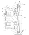
ここで、本実施形態に係る動力伝達装置は、出力シャフト3(出力部材)を介して第1クラッチ部材4aに回転力が入力されると、第2クラッチ部材4bを移動させて駆動側クラッチ板6と被動側クラッチ板7とを圧接させ得るバックトルク伝達用カム(カム面K1、T1)を有している。かかるバックトルク伝達用カムは、図6、7、9、10に示すように、第1クラッチ部材4a及び第2クラッチ部材4bの合わせ面(組み合わせ時の合わせ面)にそれぞれ一体形成されたカム面(K1、T1)により構成されている。
Here, in the power transmission device according to the present embodiment, when rotational force is input to the first
カム面K1は、図6、9に示すように、第1クラッチ部材4aに形成されたフランジ面4acの内径側(第2クラッチ部材4bとの合わせ面)において、その全周に亘って複数形成された勾配面から成り、当該第1クラッチ部材4aの周縁部に沿って円環状に複数形成された溝部Kの一方の端面に形成されている。すなわち、第1クラッチ部材4aには、その周方向に亘って複数の溝部Kが形成されており、各溝部Kの一方の端面が勾配面とされてバックトルク伝達用カムのカム面K1を構成しているのである。なお、各溝部Kの他方の端面は、第1クラッチ部材4aの軸方向に延びた壁面K2とされている。
As shown in FIGS. 6 and 9, a plurality of cam surfaces K1 are formed along the entire circumference of the flange surface 4ac formed on the first
カム面T1は、図7、10に示すように、第2クラッチ部材4bの底面(第1クラッチ部材4aとの合わせ面)において、その全周に亘って複数形成された勾配面から成り、当該第2クラッチ部材4bの底面に沿って円環状に複数形成された突出部Tの一方の端面に形成されている。すなわち、第2クラッチ部材4bには、その周方向に亘って複数の突出部Tが形成されており、各突出部Tの一方の端面が勾配面とされてバックトルク伝達用カムのカム面T1を構成しているのである。なお、各突出部Tの他方の端面は、第2クラッチ部材4bの軸方向に延びた壁面T2とされている。
As shown in FIGS. 7 and 10, the cam surface T1 consists of a plurality of sloped surfaces formed along the entire circumference of the bottom surface of the second
そして、溝部Kに突出部Tを嵌入させて第1クラッチ部材4aと第2クラッチ部材4bとを組み合わせると、図17に示すように、カム面K1とカム面T1とが対峙してバックトルク伝達用カムを構成するとともに、壁面K2と壁面T2とが所定寸法離間して対峙するようになっている。しかして、出力シャフト3を介して第1クラッチ部材4aに回転力が入力されると、第1クラッチ部材4aが第2クラッチ部材4bに対して相対的に回転するので、図18に示すように、カム面K1とカム面T1とのカムの作用によって、第1クラッチ部材4aに対して第2クラッチ部材4bを図2、18中右側に移動させる。
When the protrusion T is fitted into the groove K and the first
一方、第2クラッチ部材4bには、図7に示すように、スプライン嵌合部4baの延長上に押圧部4bbが形成されており、当該第2クラッチ部材4bが図2中右側に移動すると、積層状態にて取り付けられた駆動側クラッチ板6及び被動側クラッチ板7のうち同図中最も左側の被動側クラッチ板7を同方向へ押圧することとなる。これにより、プレッシャ部材5が非作動位置にあっても、駆動側クラッチ板6と被動側クラッチ板7とを圧接させることができ、出力シャフト3(出力部材)から回転力が入力された際、その回転力をエンジン側に伝達させてエンジンブレーキを生じさせることができる。
On the other hand, as shown in FIG. 7, the second
特に、本実施形態に係るバックトルク伝達用カムは、連動部材9に対して近接する方向(図2中右側)に第2クラッチ部材4bを移動させて当該連動部材9とウェイト部材8との当接を保持し得るよう構成されている。すなわち、バックトルク伝達用カムが作動して、第2クラッチ部材4bを図2中右側に向かって移動させると、駆動側クラッチ板6及び被動側クラッチ板7を圧接させるとともに、プレッシャ部材5を同方向に押圧するので、その押圧力がクラッチスプリング11を介して連動部材9に伝達され、当該連動部材9とウェイト部材8との当接が保持されるのである。
In particular, the back torque transmission cam according to the present embodiment moves the second
しかして、バックトルク伝達用カムの作動時、連動部材9とウェイト部材8とが離間してしまうと、その後、クラッチハウジング2の回転に伴ってウェイト部材8が内径側位置と外径側位置との間を移動しても、その移動に連動部材9を追従させることができない場合があるのに対し、本実施形態によれば、バックトルク伝達用カムの作動時においても、連動部材9とウェイト部材8との当接を保持させることができるので、ウェイト部材8の移動に連動部材9を安定して追従させることができる。
If the interlocking
さらに、本実施形態に係るバックトルク伝達用カムを構成するカム面K1、T1は、第2クラッチ部材4bに取り付けられた被動側クラッチ板7の円環形状に沿って複数形成されている。すなわち、バックトルク伝達用カムが作動する際、押圧部4bbにて押圧される被動側クラッチ板7の投影形状(円環形状)に沿ってカム面K1、T1が形成されているのである。これにより、バックトルク伝達用カムの作用によって、押圧部4bbが被動側クラッチ板7に対して略均等の押圧力を付与することができ、より効率的に駆動側クラッチ板6と被動側クラッチ板7とを圧接させることができる。
Further, a plurality of cam surfaces K1 and T1, which constitute the back torque transmitting cam according to the present embodiment, are formed along the annular shape of the driven side
またさらに、本実施形態に係るバックトルク伝達用カム(カム面K1及びカム面T1で構成されるカム)は、バックトルクリミッタ用カム(勾配面4ab及び勾配面5bで構成されるカム)の作動前に作動し得る構成とされている。すなわち、カム面K1及びカム面T1の間のクリアランス(間隙寸法)は、勾配面4ab及び勾配面5bの間のクリアランス(間隙寸法)よりも小さく設定されており、バックトルクリミッタ用カムの作動前にバックトルク伝達用カムが作動し得るようになっている。
Furthermore, the back torque transmission cam (the cam composed of the cam surface K1 and the cam surface T1) according to the present embodiment operates the back torque limiter cam (the cam composed of the inclined surface 4ab and the
さらに、本実施形態に係る動力伝達装置においては、第1クラッチ部材4a及び第2クラッチ部材4bにそれぞれ形成され、第2クラッチ部材4bに伝達された回転力をバックトルク伝達用カム(カム面K1及びカム面T1)を介さず第1クラッチ部材4aに伝達し得るトルク伝達部と、第1クラッチ部材4a及び第2クラッチ部材4bにそれぞれ形成され、バックトルク伝達用カム(カム面K1及びカム面T1)による第2クラッチ部材4bの移動量を制限する移動量制限部とを具備している。
Further, in the power transmission device according to the present embodiment, the torque transmitted to the second
すなわち、第1クラッチ部材4aには、図6、9に示すように、凸部Fが周方向に亘って等間隔に複数(本実施形態においては3つ)一体形成されており、第2クラッチ部材4bには、図7、9に示すように、内側に向かって延びた突出部Gが一体形成されている。そして、第1クラッチ部材4aと第2クラッチ部材4bとが組み付けられると、図15、16に示すように、一つの凸部Fが2つの突出部Gに挟まれた状態となっており、凸部Fの一側面F1と一方の突出部Gの当接面(第1当接面G1)とが対峙するとともに、凸部Fの他側面F2と他方の突出部Gの当接面(第2当接面G2)とが対峙するよう構成されている。
That is, as shown in FIGS. 6 and 9, the first
しかして、第1クラッチ部材4aに形成された凸部Fの一側面F1と第2クラッチ部材4bに形成された一方の突出部Gの第1当接面G1とは、本実施形態に係るトルク伝達部を構成している。すなわち、プレッシャ部材5が作動位置に移動して駆動側クラッチ板6及び被動側クラッチ板7が圧接されてクラッチがオン(駆動力を伝達)すると、バックトルク伝達用カムにおける溝部Kの壁面K2と突出部Tの壁面T2との離間状態(図17参照)が保持されつつ、図15に示すように、凸部の一側面F1と突出部Gの第1当接面G1とが当接し、第2クラッチ部材4bの回転力を受けて第1クラッチ部材4aに伝達し得るのである。
Thus, the one side surface F1 of the protrusion F formed on the first
また、第1クラッチ部材4aに形成された凸部Fの他側面F2と第2クラッチ部材4bに形成された他方の突出部Gの第2当接面G2とは、本実施形態に係る移動量制限部を構成している。すなわち、出力シャフト3を介して第1クラッチ部材4aに回転力が入力されると、第1クラッチ部材4aと第2クラッチ部材4bとが相対的に回転するので、バックトルク伝達用カムにおける溝部Kのカム面K1と突出部Tのカム面T1とのカムの作用により第2クラッチ部材4bが移動する(図18参照)。そして、その移動量が設定値に達すると、図16に示すように、凸部の他側面F2と突出部Gの第2当接面G2とが当接し、第1クラッチ部材4aに対する第2クラッチ部材4bの相対回転が規制されるので、バックトルク伝達用カムが作動した際の第2クラッチ部材4bの移動量を制限することができる。
Further, the other side surface F2 of the protrusion F formed on the first
本実施形態においては、第1クラッチ部材4aに凸部Fを形成し、第2クラッチ部材4bに突出部Gを形成しているが、これに代えて、第1クラッチ部材4bに突出部Gを形成し、第2クラッチ部材4bに凸部Fを形成するようにしてもよい。この場合、第2クラッチ部材4bに形成された凸部Fの一側面F1と第1クラッチ部材4aに形成された一方の突出部Gの第1当接面G1とは、本実施形態に係るトルク伝達部を構成するとともに、第2クラッチ部材4bに形成された凸部Fの他側面F2と第1クラッチ部材4bに形成された他方の突出部Gの第2当接面G2とは、本実施形態に係る移動量制限部を構成する。
In the present embodiment, the protrusion F is formed on the first
次に、本実施形態におけるバックトルク伝達用カムの作用について説明する。
エンジンが停止又はアイドリング状態のとき、入力ギア1にエンジンの駆動力が伝達されない或いは入力ギア1の回転数が低回転であるため、図2に示すように、ウェイト部材8が内径側位置とされるとともに、プレッシャ部材5が非作動位置とされている。このとき、出力シャフト3(出力部材)を介して第1クラッチ部材4aに回転力が入力されると、バックトルク伝達用カムの作用によって、第2クラッチ部材4bが同図中右側に移動し、駆動側クラッチ板6及び被動側クラッチ板7が圧接されてエンジン側に回転力を伝達させる。
Next, the action of the back torque transmission cam in this embodiment will be described.
When the engine is stopped or idling, the driving force of the engine is not transmitted to the
車両の停止又はアイドリング状態の後、車両が発進するとき、入力ギア1の回転数が低回転から高回転に移行(中回転域)するため、ウェイト部材8が内径側位置と外径側位置との間とされるとともに、プレッシャ部材5が作動位置とされている。このとき、下り坂でアクセルオフするなどして、出力シャフト3(出力部材)を介して第1クラッチ部材4aに回転力が入力されると、バックトルク伝達用カムの作用によって、第2クラッチ部材4bが同図中右側に移動し、駆動側クラッチ板6及び被動側クラッチ板7が圧接されてエンジン側に回転力を伝達させる。
When the vehicle starts after stopping or idling, the rotation speed of the
車両が発進した後、加速し、高速域で走行するとき、入力ギア1の回転数が高回転であるため、ウェイト部材8が外径側位置とされるとともに、プレッシャ部材5が作動位置とされている。このとき、シフトダウン等により、出力シャフト3(出力部材)を介して第1クラッチ部材4aに回転力が入力されると、バックトルク伝達用カムの作用によって、第2クラッチ部材4bが同図中右側に移動し、駆動側クラッチ板6及び被動側クラッチ板7が圧接されてエンジン側に回転力を伝達させる。
When the vehicle is accelerated and runs in a high-speed range after starting, the rotation speed of the
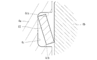
ここで、本実施形態においては、第1クラッチ部材4aと第2クラッチ部材4bとの間に介在され、連動部材9が移動してプレッシャ部材5が非作動位置から作動位置に向かう過程で圧縮する(スプリングが撓む)ことにより連動部材9及びプレッシャ部材5の移動を許容しつつ付勢力を付与し得る緩衝部材12を具備している。かかる緩衝部材12は、クラッチスプリング11が圧縮開始する前に圧縮される荷重に設定されたスプリングから成り、図2、3、21に示すように、第1クラッチ部材4a及び第2クラッチ部材4bが対峙する面(具体的には、第1クラッチ部材4aにおける第2クラッチ部材4bと対峙する面)に形成された収容凹部4cに収容されて組み付けられている。
Here, in the present embodiment, the interlocking
より具体的には、収容凹部4cは、図6に示すように、円環状に形成された溝から成るとともに、緩衝部材12は、当該溝形状に倣って円環状に形成された皿バネから成る。また、収容凹部4cは、図19に示すように、内径側の壁面4caと、外径側の壁面4cbとを有する溝から成り、円環状のスプリングから成る緩衝部材12が当該溝形状に倣って嵌まり込むようになっている。
More specifically, as shown in FIG. 6, the
しかして、本実施形態に係るバックトルク伝達用カムは、既述のように、第1クラッチ部材4a及び第2クラッチ部材4bが対峙する面において円環状に複数形成されるとともに、収容凹部4cは、図6に示すように、バックトルク伝達用カムと隣接した位置(本実施形態においては、バックトルク伝達用カムの形成位置より内径側)に同心円状に形成されている。なお、本実施形態においては、収容凹部4cがバックトルク伝達用カムの形成位置より内径側に同心円状に形成されているがバックトルク伝達用カムの形成位置より外径側に同心円状に形成されていてもよく、この場合、図24に示すように、緩衝部材12は、駆動側クラッチ板6及び被動側クラッチ板7が積層された部位(ディスクパック)に対し、当該駆動側クラッチ板6及び被動側クラッチ板7を圧接する方向に付勢力を付与するよう構成してもよい。
Thus, in the back torque transmission cam according to the present embodiment, as described above, a plurality of annular cams are formed on the surfaces where the first
次に、本実施形態に係る緩衝部材12の作用について、従来の緩衝部材12を具備していないものと比較して説明する。
先ず、本実施形態の如く緩衝部材12を具備していない場合の作用について、図32のグラフ(連動部材9の移動量(mm)を横軸、連動部材9に対して生じる押し付け荷重(N)を縦軸としたグラフ)を用いて説明する。なお、図32のグラフ中、P1はレリーズスプリングmの撓み量(圧縮量)が最大となった時点(レリーズスプリングmの最大荷重に達した時点)の連動部材9の押し付け荷重、P2はクラッチスプリング11が撓み始める時点(クラッチスプリング11のセット荷重に達した時点)の連動部材9の押し付け荷重、図22、23のグラフ中P3は、緩衝部材12が撓み始める時点(緩衝部材12のセット荷重に達した時点)の連動部材9の押し付け荷重となっている。
Next, the action of the cushioning
32 (horizontal axis represents the amount of movement (mm) of the interlocking
エンジンの回転数が上昇してウェイト部材8が内径側位置から外径側位置に移動することによって連動部材9が移動する過程において、当該連動部材9の移動量がαに達するまでレリーズスプリングmが撓みつつクラッチスプリング11は撓まない状態(すなわち、連動部材9及びプレッシャ部材5が一体として移動)とされるとともに、連動部材9の移動量がαに達すると、押し付け荷重(N)がP1からP2に上昇するものの、連動部材9が移動しなくなり、不感帯領域となる。
In the process of moving the interlocking
そのような状態から押し付け荷重(N)がP2(クラッチスプリング11のセット荷重)に達すると、クラッチスプリング11が撓み始め、連動部材9の移動に伴って押し付け荷重(N)が増加することとなる。よって、押し付け荷重(N)がP1からP2に達するまで、連動部材12及びプレッシャ部材5が停止し、P2に達した途端にクラッチスプリング11の圧縮が開始され、クラッチ板(駆動側クラッチ板6及び被動側クラッチ板7)が圧接して動力が伝達されるので、動力伝達時の唐突感があった。
When the pressing load (N) reaches P2 (the set load of the clutch spring 11) from such a state, the
これに対し、本実施形態においては、連動部材9が移動する過程において、クラッチスプリング11が圧縮開始する前に圧縮される荷重に設定されたスプリング(セット荷重がP3に設定されたスプリング)から成る緩衝部材12を具備しているので、図22に示すように、連動部材9の移動量がβに達した時点から緩衝部材12が圧縮開始(撓み開始)され、押し付け荷重がP2に達する時点まで圧縮が継続されることとなる。
On the other hand, in the present embodiment, in the process of moving the interlocking
すなわち、本グラフによれば、エンジンの回転数が上昇してウェイト部材8が内径側位置から外径側位置に移動することによって連動部材9が移動する過程において、連動部材9の移動量がβとなって押し付け荷重(N)がP3に達した時点から、緩衝部材12が圧縮されることとなり、その後、連動部材9の移動量がαに達して押し付け荷重(N)がP2となることにより、クラッチスプリング11が撓み始める(圧縮開始する)ことが分かる。
That is, according to this graph, in the process of moving the interlocking
このように、連動部材9が移動開始するとき、押し付け荷重(N)がレリーズスプリングmのセット荷重となって当該レリーズスプリングmが撓み始め(圧縮開始)、連動部材の移動量がβに達すると、緩衝部材12が撓み始め(圧縮開始)、その後、連動部材9の移動量がαに達すると、レリーズスプリングmが最大荷重に達するとともに、押し付け荷重(N)がクラッチスプリング11のセット荷重(P2)に達することにより、当該クラッチスプリング11が撓み始める(圧縮開始する)よう構成されている。そして、クラッチスプリング11は、最大荷重(作動荷重の上限)に達するまで、連動部材9の移動によって継続して圧縮する(撓み続ける)こととなる。
As described above, when the interlocking
したがって、連動部材9の移動量がβからαの間においては、押し付け荷重がP3からP2まで増加する過程で緩衝部材12が継続的に圧縮して(撓んで)当該連動部材9の移動が許容されるので、従来の不感帯領域を低減し、ウェイト部材8及び連動部材9を円滑且つ継続的に移動させることができる。よって、クラッチ締結時のショックを抑制して動力伝達時の唐突感を抑制することができる。
Therefore, when the amount of movement of the interlocking
なお、上記した緩衝部材12は、図22に示すように、押し付け荷重(N)がP3からP2の間で継続して圧縮される(撓み続ける)ものとされているが、図23に示すように、連動部材9の移動量がβとなり押し付け荷重(N)がP3に達した時点から緩衝部材12が圧縮開始(撓み開始)され、且つ、押し付け荷重(N)がP2より低いP4となった時点まで緩衝部材12が継続的に圧縮される(撓み続ける)よう設定してもよい。この場合であっても、従来の不感帯領域を従来より低減することができるので、ウェイト部材8及び連動部材9を円滑且つ継続的に移動させることができ、クラッチ締結時のショックを抑制して動力伝達時の唐突感を抑制できる。
As shown in FIG. 22, the cushioning
本実施形態によれば、第1クラッチ部材4aと第2クラッチ部材4bとの間に介在され、連動部材9が移動してプレッシャ部材5が非作動位置から作動位置に向かう過程で圧縮することにより連動部材9及びプレッシャ部材5の移動を許容しつつ付勢力を付与し得る緩衝部材12を具備したので、第1クラッチ部材4a及び第2クラッチ部材4bの配設に伴って得られるスペースを有効活用しつつ動力伝達時の唐突感を抑制して操作性を向上させることができる。
According to the present embodiment, interlocking
また、本実施形態に係る緩衝部材12は、クラッチスプリング11が圧縮開始する前に圧縮される荷重に設定されたスプリングから成るので、動力伝達時の唐突感をより確実に抑制することができる。特に、緩衝部材12のセット荷重や作動荷重を任意に設定することにより、適用される車両の形態に合わせて動力伝達時の感覚(発進フィーリング)を種々設定することができる。
In addition, since the cushioning
さらに、本実施形態に係る緩衝部材12は、第1クラッチ部材4a及び第2クラッチ部材4bが対峙する面に形成された収容凹部4cに収容されたので、第1クラッチ部材4aに対して第2クラッチ部材4bが移動する際、緩衝部材12が巻き込まれて位置ずれが生じてしまうのを回避することができる。なお、本実施形態に係る収容凹部4cは、第1クラッチ部材4aにおける第2クラッチ部材4bと対峙する面に形成されているが、第2クラッチ部材4bにおける第1クラッチ部材4aと対峙する面に形成するようにしてもよい。
Furthermore, since the cushioning
またさらに、本実施形態に係る収容凹部4cは、円環状に形成された溝から成るとともに、緩衝部材12は、当該溝形状に倣って円環状に形成されたスプリングから成るので、緩衝部材12で生じた付勢力を第2クラッチ部材4b等に対して略均一に付与させることができ、付勢力を安定して付与させることができる。また、本実施形態に係るバックトルク伝達用カムは、第1クラッチ部材4a及び第2クラッチ部材4bが対峙する面において円環状に複数形成されるとともに、収容凹部4cは、当該バックトルク伝達用カムと隣接した位置に同心円状に形成されたので、バックトルク伝達用カムによる第2クラッチ部材4bの移動と、緩衝部材12による付勢力の付与とを確実且つ安定して行わせることができる。
Furthermore, the
加えて、本実施形態に係るベアリング保持部材Cは、一端が開口した円筒状部材から成り、その開口端部Caがクラッチ部材(第1クラッチ部材4a)に形成された凹部4dに嵌入して取り付けられた(インロー状態にて取り付けられた)ので、ベアリング保持部材Cの組み付けを容易に行わせることができるとともに、変速操作時に安定してベアリング保持部材Cを動作させることができる。
In addition, the bearing holding member C according to the present embodiment is made of a cylindrical member with one end open, and the open end Ca is fitted into the
また、駆動側クラッチ板6及び被動側クラッチ板7が圧接される前の締結状態に達するまで連動部材9及びプレッシャ部材5の移動を許容しつつプレッシャ部材5に付勢力を付与し得るレリーズスプリングmを具備して構成され、当該レリーズスプリングmは、ベアリング保持部材C及びプレッシャ部材5の両部材に亘って取り付けられ、プレッシャ部材5に付勢力を付与するとともに、ベアリング保持部材Cに付勢力を付与して作動部材10に当該付勢力を伝達させ得るので、レリーズスプリングmによって、変速操作手段の遊びを防止するスプリングを兼用させることができ、部品点数を削減できる。
In addition, the release spring m can apply an urging force to the
さらに、本実施形態に係るレリーズスプリングmは、中央部maと周縁部mbとの変位により付勢力を生じさせ得る円形状の皿バネから成り、中央部maがベアリング保持部材Cに取り付けられるとともに、周縁部mbがプレッシャ部材5に取り付けられたので、ベアリング保持部材Cとプレッシャ部材5との両方に安定してレリーズスプリングmの付勢力を付与させることができる。
Further, the release spring m according to the present embodiment is a circular disc spring that can generate a biasing force by displacement between the central portion ma and the peripheral portion mb. The central portion ma is attached to the bearing holding member C, Since the peripheral portion mb is attached to the
またさらに、本実施形態に係るクラッチ部材は、出力シャフト3(出力部材)と連結される第1クラッチ部材4aと、被動側クラッチ板7が取り付けられる第2クラッチ部材4bと、出力シャフト3(出力部材)を介して第1クラッチ部材4aに回転力が入力されると、第2クラッチ部材4bを移動させて駆動側クラッチ板6と被動側クラッチ板7とを圧接させ得るバックトルク伝達用カムとを有するとともに、凹部4dは、第1クラッチ部材4aに形成されたので、ベアリング保持部材Cがバックトルク伝達用カムによる第2クラッチ部材4bの移動を妨げてしまうのを回避でき、ベアリング保持部材Cの動作と、バックトルク伝達用カムによる第2クラッチ部材4bの移動とをそれぞれ円滑に行わせることができる。
Furthermore, the clutch member according to the present embodiment includes a first
なお、上記実施形態によれば、バックトルク伝達用カムは、連動部材9に対して近接する方向に第2クラッチ部材4bを移動させて当該連動部材9とウェイト部材8との当接を保持し得るので、駆動側クラッチ板6及び被動側クラッチ板7を圧接させることにより車輪側の回転力をエンジン側に伝達してエンジンブレーキを生じさせることができるとともに、エンジンブレーキを生じさせた際のウェイト部材8による作動を安定して行わせることができる。
According to the above embodiment, the back torque transmission cam moves the second
また、本実施形態に係るバックトルク伝達用カムは、第1クラッチ部材4a及び第2クラッチ部材4bのそれぞれに一体形成されたカム面(K1、T1)にて構成され、当該カム面(K1、T1)は、第1クラッチ部材4a及び第2クラッチ部材4bの合わせ面にそれぞれ形成されたので、バックトルク伝達用カムによる第2クラッチ部材2bの移動を確実且つ円滑に行わせることができる。
Further, the back torque transmission cam according to the present embodiment is composed of cam surfaces (K1, T1) formed integrally with the first
さらに、第1クラッチ部材4aに形成された勾配面4aaとプレッシャ部材5に形成された勾配面5aとを対峙させて構成され、入力ギア1(入力部材)に入力された回転力が出力シャフト3(出力部材)に伝達され得る状態となったときに駆動側クラッチ板6と被動側クラッチ板7との圧接力を増加させるための圧接アシスト用カムを具備したので、遠心力によるウェイト部材8の移動に伴う圧接力に加えて圧接アシスト用カムによる圧接力を付与させることができ、より円滑かつ確実に駆動側クラッチ板6と被動側クラッチ板7とを圧接させることができる。
Further, a sloped surface 4aa formed on the first
またさらに、第1クラッチ部材4aに形成された勾配面4abとプレッシャ部材5に形成された勾配面5bとを対峙させて構成され、出力シャフト3(出力部材)の回転が入力ギア1(入力部材)の回転数を上回って当該クラッチ部材(第1クラッチ部材4a)とプレッシャ部材5とが相対的に回転したとき、駆動側クラッチ板6と被動側クラッチ板7との圧接力を解放させ得るバックトルクリミッタ用カムを具備したので、ウェイト部材8が外径側位置にあるとき、入力ギア1を介してエンジン側に過大な動力が伝達されてしまうのを回避することができるとともに、バックトルクリミッタ用カムの作動前にバックトルク伝達用カムを作動させる構成とされたので、バックトルク伝達用カムによる作動を確実に行わせることができる。
Further, the inclined surface 4ab formed on the first
加えて、本実施形態によれば、出力シャフト3(出力部材)を介して第1クラッチ部材4aに回転力が入力されると、第2クラッチ部材4bを移動させて駆動側クラッチ板6と被動側クラッチ板7とを圧接させ得るバックトルク伝達用カムと、第1クラッチ部材4a及び第2クラッチ部材4bにそれぞれ形成され、第2クラッチ部材4bに伝達された回転力をバックトルク伝達用カム(カム面K1及びカム面T1)を介さず第1クラッチ部材4aに伝達し得るトルク伝達部とを具備したので、駆動側クラッチ板6及び被動側クラッチ板7を圧接させることにより車輪側の回転力をエンジン側に伝達してエンジンブレーキを生じさせることができるとともに、ウェイト部材8が外径側位置に移動してプレッシャ部材5が作動位置に移動するときの動力伝達を安定して行わせることができる。
In addition, according to the present embodiment, when a rotational force is input to the first
また、第1クラッチ部材4a及び第2クラッチ部材4bにそれぞれ形成され、バックトルク伝達用カムによる第2クラッチ部材4bの移動量を制限する移動量制限部を具備したので、バックトルク伝達用カムによる第2クラッチ部材4bの移動を設定された範囲内にて行わせることができる。
Further, since the first
さらに、第1クラッチ部材4a及び第2クラッチ部材4bの何れか一方に凸部Fが形成されるとともに、トルク伝達部は、当該凸部Fの一側面F1と該一側面F1と当接して回転力を受け得る第1当接面G1とから成るとともに、移動量制限部は、当該凸部Fの他側面F2と該他側面F2と当接して移動量を制限し得る第2当接面G2とから成るので、トルク伝達部及び移動量制限部の機能を凸部Fが兼用して行わせることができる。
Further, a convex portion F is formed on either one of the first
以上、本実施形態について説明したが、本発明はこれらに限定されるものではなく、例えば図25、26に示すように、クラッチハウジング2の筐体部2aにウェイト部材8を移動可能に配設したものに適用してもよい。かかる動力伝達装置は、上記実施形態と同様、第1クラッチ部材4a、第2クラッチ部材4b及びバックトルク伝達用カムを有するとともに、第1クラッチ部材4aと第2クラッチ部材4bとの間に緩衝部材12が介在して構成されている。
Although the present embodiment has been described above, the present invention is not limited to this. For example, as shown in FIGS. It may be applied to This power transmission device has a first
また、図25においては、第1クラッチ部材4aにおける第2クラッチ部材4bと対峙する面に緩衝部材12が取り付けられた実施形態を示すとともに、図26においては、第1クラッチ部材4aにおける駆動側クラッチ板6及び被動側クラッチ板7が積層された部位(ディスクパック)に対し付勢力を付与する緩衝部材12が取り付けられた実施形態を示している。なお、ベアリング保持部材C’は、作動部材10’により移動可能とされるとともに、レリーズスプリングm’は、ベアリング保持部材C’及びプレッシャ部材5の両部材に亘って取り付けられたコイルスプリングから成るものとされている。
FIG. 25 shows an embodiment in which a cushioning
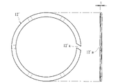
さらに、皿バネから成る緩衝部材12に代えて、他の弾性部材としてもよく、例えば図27に示すように、ウェーブスプリングから成る緩衝部材12’が収容凹部4cに配設されたものであってもよい。かかるウェーブスプリングは、図28、29に示すように、円環形状の一部に切欠き部12’aを有したC字状部材から成り、厚み方向tに対して波形(ウェーブ形状)に形成されて弾力を生じ得るもので、第1クラッチ部材4a及び第2クラッチ部材4bとの間に介在され、連動部材9が移動してプレッシャ部材5が非作動位置から作動位置に向かう過程で圧縮することにより連動部材9及びプレッシャ部材5の移動を許容しつつ付勢力を付与し得るよう構成されている。
Furthermore, instead of the cushioning
なお、同図で示される動力伝達装置において、ベアリング保持部材Cは、その側壁に連通孔Ccが複数(本実施形態においては3つ)形成されており、オイル流路rを介してベアリング保持部材C内に供給されたオイルを外部に流出させ得るようになっている。また、作動部材10”は、ベアリング保持部材CのローラベアリングB1に係止され、運転者の操作やアクチュエータの作動によって同図中左右方向に移動することにより、プレッシャ部材5を作動位置と非作動位置との間で移動可能とされている。
In the power transmission device shown in the figure, the bearing holding member C has a plurality of communication holes Cc (three in this embodiment) formed in its side wall, and the bearing holding member C is formed through the oil flow path r. The oil supplied in C can flow out to the outside. The actuating member 10'' is engaged with the roller bearing B1 of the bearing holding member C, and is moved in the lateral direction in the drawing by the operation of the driver or the actuation of the actuator, thereby moving the
またさらに、図30に示すように、第1クラッチ部材4a及び第2クラッチ部材4bの外周縁部にバックトルク伝達用カム(カム面K1及びカム面T1)が配設されたものであってもよい。かかる動力伝達装置によれば、第1クラッチ部材4a及び第2クラッチ部材4bの外周縁部にバックトルク伝達用カムが配設されるので、カムの作用を大きくすることができ、第2クラッチ部材4bの移動力を大きく設定できる。なお、同図においては、バックトルク伝達用カム(カム面K1及びカム面T1)の内径側に皿バネから成る緩衝部材12が配設されているが、かかる皿バネに代えて、ウェーブスプリングから成る緩衝部材12’を配設するようにしてもよい。
Furthermore, as shown in FIG. 30, even if back torque transmission cams (cam surface K1 and cam surface T1) are arranged on the outer peripheral edge portions of the first
また、本実施形態においては、ベアリング保持部材Cは、一端が開口した円筒状部材から成り、その開口端部Caがクラッチ部材(第1クラッチ部材4a)に形成された凹部4dに嵌入して取り付けられているが、他の形状のベアリング保持部材であってもよく、クラッチ部材に形成された凹部に嵌合する形態(所謂インロー)とは相違する取付構造であってもよい。なお、本発明の動力伝達装置は、自動二輪車の他、自動車、3輪又は4輪バギー、或いは汎用機等種々の多板クラッチ型の動力伝達装置に適用することができる。
Further, in the present embodiment, the bearing holding member C is made of a cylindrical member with one end opened, and the open end Ca is fitted into the
クラッチ部材は、出力部材と連結される第1クラッチ部材と、被動側クラッチ板が取り付けられる第2クラッチ部材と、出力部材を介して第1クラッチ部材に回転力が入力されると、第2クラッチ部材を移動させて駆動側クラッチ板と被動側クラッチ板とを圧接させ得るバックトルク伝達用カムとを有するとともに、第1クラッチ部材と第2クラッチ部材との間に介在され、連動部材が移動してプレッシャ部材が非作動位置から作動位置に向かう過程で圧縮することにより連動部材及びプレッシャ部材の移動を許容しつつ付勢力を付与し得る緩衝部材を具備した動力伝達装置であれば、外観形状が異なるもの或いは他の機能が付加されたもの等にも適用することができる。 The clutch member includes a first clutch member connected to the output member, a second clutch member to which the driven clutch plate is attached, and when rotational force is input to the first clutch member via the output member, the second clutch It has a back torque transmission cam that can move a member to bring the driving side clutch plate and the driven side clutch plate into pressure contact, and is interposed between the first clutch member and the second clutch member so that the interlocking member moves. A power transmission device having a buffer member capable of imparting an urging force while allowing movement of the interlocking member and the pressure member by compressing the pressure member in the process of moving from the non-operating position to the operating position. It can also be applied to a different one or one to which other functions are added.
1 入力ギア(入力部材)
2 クラッチハウジング
2a 筐体部
2b カバー部
3 出力シャフト(出力部材)
4a 第1クラッチ部材
4aa 勾配面(圧接アシスト用カム)
4ab 勾配面(バックトルクリミッタ用カム)
4ac フランジ面
4ad 挿通孔
4b 第2クラッチ部材
4ba スプライン嵌合部
4bb 押圧部
4c 収容凹部
4d 凹部
4da 内周壁面
5 プレッシャ部材
5a 勾配面(圧接アシスト用カム)
5b 勾配面(バックトルクリミッタ用カム)
5c フランジ面
6 駆動側クラッチ板
7 被動側クラッチ板
8 ウェイト部材
9 連動部材
10 作動部材
11 クラッチスプリング
12 緩衝部材(皿バネ)
12’ 緩衝部材(ウェーブスプリング)
12’a 切欠き部
C ベアリング保持部材
Ca 開口端部
Cb 頂部
Cc 連通孔
K 溝部
K1 カム面
K2 壁面
T 突出部
T1 カム面
T2 壁面
F 凸部
G 突出部
G1 第1当接面
G2 第2当接面
m レリーズスプリング
r オイル流路
1 Input gear (input member)
2
4a First clutch member 4aa Inclined surface (pressure assist cam)
4ab Inclined surface (cam for back torque limiter)
4ac flange surface
5b Inclined surface (cam for back torque limiter)
12' buffer member (wave spring)
12'a Notch portion C Bearing holding member Ca Opening end portion Cb Top portion Cc Communication hole K Groove portion K1 Cam surface K2 Wall surface T Projection portion T1 Cam surface T2 Wall surface F Projection portion G Projection portion G1 First contact surface G2 Second contact Contact surface m Release spring r Oil passage
Claims (6)
前記クラッチハウジングの前記駆動側クラッチ板と交互に形成された複数の被動側クラッチ板が取り付けられるとともに、前記車両の車輪を回転させ得る出力部材と連結されたクラッチ部材と、
前記駆動側クラッチ板と前記被動側クラッチ板とを圧接させて前記エンジンの駆動力を前記車輪に伝達可能な状態とする作動位置と、前記駆動側クラッチ板と前記被動側クラッチ板との圧接力を解放させて前記エンジンの駆動力が前記車輪に伝達されるのを遮断し得る非作動位置との間で移動可能なプレッシャ部材と、
前記クラッチハウジングの回転に伴う遠心力で内径側位置から外径側位置に移動可能とされたウェイト部材と、
前記ウェイト部材が前記内径側位置から前記外径側位置に移動するのに伴って、前記プレッシャ部材を前記非作動位置から前記作動位置に移動させ得る連動部材と、
前記プレッシャ部材を前記非作動位置に保持し得るとともに、前記連動部材が移動して前記プレッシャ部材が前記非作動位置から前記作動位置に向かって移動するのに伴って圧縮されるレリーズスプリングと、
前記駆動側クラッチ板及び前記被動側クラッチ板とが圧接された状態に達した後、前記連動部材が移動する過程で圧縮されるクラッチスプリングと、
を有した動力伝達装置において、
前記クラッチ部材は、
前記出力部材と連結される第1クラッチ部材と、
前記被動側クラッチ板が取り付けられる第2クラッチ部材と、
前記出力部材を介して前記第1クラッチ部材に回転力が入力されると、前記第2クラッチ部材を移動させて前記駆動側クラッチ板と前記被動側クラッチ板とを圧接させ得るバックトルク伝達用カムと、
を有するとともに、前記第1クラッチ部材と前記第2クラッチ部材との間に介在され、前記連動部材が移動して前記プレッシャ部材が前記非作動位置から前記作動位置に向かう過程で圧縮することにより前記連動部材及び前記プレッシャ部材の移動を許容しつつ付勢力を付与し得る緩衝部材を具備したことを特徴とする動力伝達装置。 A clutch member that rotates together with an input member that rotates with the driving force of a vehicle engine and is accommodated in a clutch housing to which a plurality of drive-side clutch plates are attached,
a clutch member mounted with a plurality of driven clutch plates alternating with the driving clutch plates of the clutch housing and connected to an output member capable of rotating a wheel of the vehicle;
an operating position in which the drive-side clutch plate and the driven-side clutch plate are brought into pressure contact so that the driving force of the engine can be transmitted to the wheels; and a pressure contact force between the drive-side clutch plate and the driven-side clutch plate. a pressure member movable between a non-operating position capable of releasing the engine driving force from being transmitted to the wheels;
a weight member movable from an inner diameter side position to an outer diameter side position by centrifugal force accompanying rotation of the clutch housing;
an interlocking member capable of moving the pressure member from the non-operating position to the operating position as the weight member moves from the inner diameter side position to the outer diameter side position;
a release spring capable of holding the pressure member at the non-operating position and being compressed as the interlocking member moves and the pressure member moves from the non-operating position toward the operating position;
a clutch spring that is compressed while the interlocking member moves after the drive-side clutch plate and the driven-side clutch plate are pressed against each other;
In a power transmission device having
The clutch member is
a first clutch member coupled with the output member;
a second clutch member to which the driven-side clutch plate is attached;
a back torque transmission cam capable of moving the second clutch member to bring the drive-side clutch plate and the driven-side clutch plate into pressure contact when a rotational force is input to the first clutch member through the output member; When,
is interposed between the first clutch member and the second clutch member, and the interlocking member moves and compresses the pressure member in the process of moving from the non-operating position to the operating position. A power transmission device comprising a buffer member capable of applying an urging force while allowing movement of the interlocking member and the pressure member.
前記クラッチハウジングの前記駆動側クラッチ板と交互に形成された複数の被動側クラッチ板が取り付けられるとともに、前記車両の車輪を回転させ得る出力部材と連結されたクラッチ部材と、
前記クラッチハウジングの回転に伴う遠心力で内径側位置から外径側位置に移動可能とされたウェイト部材と、
前記ウェイト部材が前記内径側位置から前記外径側位置に移動するのに伴って、前記駆動側クラッチ板および前記被動側クラッチ板を、圧接力が解放された非作動状態から、互いに圧接させて前記エンジンの駆動力を前記車輪に伝達可能な作動状態に切り替える連動部材と、
を有した動力伝達装置において、
前記クラッチ部材は、
前記出力部材と連結される第1クラッチ部材と、
前記被動側クラッチ板が取り付けられる第2クラッチ部材と、
前記出力部材を介して前記第1クラッチ部材に回転力が入力されると、前記第2クラッチ部材を移動させて前記駆動側クラッチ板と前記被動側クラッチ板とを圧接させ得るバックトルク伝達用カムと、
を有するとともに、前記連動部材が移動して前記駆動側クラッチ板および前記被動側クラッチ板が前記非作動状態から前記作動状態に切り替わる過程で圧縮することにより前記連動部材の移動を許容しつつ付勢力を付与し得る緩衝部材を具備し、さらに、
前記バックトルク伝達用カムは、第1のカム面を有する第1部分と、前記第1部分と対向するように配置されたときに前記第1のカム面と対向する第2のカム面を有する第2部分と、を含み、
前記第2部分は、前記出力部材の軸方向に延び、かつ、前記出力部材の径方向から見て前記緩衝部材と重なることを特徴とする動力伝達装置。 A clutch member that rotates together with an input member that rotates with the driving force of a vehicle engine and is accommodated in a clutch housing to which a plurality of drive-side clutch plates are attached,
a clutch member mounted with a plurality of driven clutch plates alternating with the driving clutch plates of the clutch housing and connected to an output member capable of rotating a wheel of the vehicle;
a weight member movable from an inner diameter side position to an outer diameter side position by centrifugal force accompanying rotation of the clutch housing;
As the weight member moves from the inner diameter side position to the outer diameter side position, the drive side clutch plate and the driven side clutch plate are brought into pressure contact with each other from the non-operating state in which the pressure contact force is released. an interlocking member that switches the driving force of the engine to an operating state in which it can be transmitted to the wheels;
In a power transmission device having
The clutch member is
a first clutch member coupled with the output member;
a second clutch member to which the driven-side clutch plate is attached;
a back torque transmission cam capable of moving the second clutch member to bring the drive-side clutch plate and the driven-side clutch plate into pressure contact when a rotational force is input to the first clutch member through the output member; When,
and an urging force while allowing the movement of the interlocking member by compressing the driving side clutch plate and the driven side clutch plate in the process of switching from the non-operating state to the operating state by moving the interlocking member. Equipped with a cushioning member capable of imparting
The back torque transmitting cam has a first portion having a first cam surface and a second cam surface facing the first cam surface when arranged to face the first portion. a second portion;
A power transmission device, wherein the second portion extends in the axial direction of the output member and overlaps the cushioning member when viewed from the radial direction of the output member.
Priority Applications (8)
| Application Number | Priority Date | Filing Date | Title |
|---|---|---|---|
| JP2018227994A JP7209520B2 (en) | 2018-12-05 | 2018-12-05 | power transmission device |
| EP19893997.7A EP3892880A4 (en) | 2018-12-05 | 2019-12-04 | Power transmission device |
| PCT/JP2019/047407 WO2020116506A1 (en) | 2018-12-05 | 2019-12-04 | Power transmission device |
| CN201980079116.XA CN113167336B (en) | 2018-12-05 | 2019-12-04 | Power transmission device |
| CN202211163254.6A CN115574011A (en) | 2018-12-05 | 2019-12-04 | Power transmission device |
| US17/336,387 US11415190B2 (en) | 2018-12-05 | 2021-06-02 | Power transmission device |
| US17/861,228 US11603892B2 (en) | 2018-12-05 | 2022-07-10 | Power transmission device |
| JP2022159460A JP7307252B2 (en) | 2018-12-05 | 2022-10-03 | power transmission device |
Applications Claiming Priority (1)
| Application Number | Priority Date | Filing Date | Title |
|---|---|---|---|
| JP2018227994A JP7209520B2 (en) | 2018-12-05 | 2018-12-05 | power transmission device |
Related Child Applications (1)
| Application Number | Title | Priority Date | Filing Date |
|---|---|---|---|
| JP2022159460A Division JP7307252B2 (en) | 2018-12-05 | 2022-10-03 | power transmission device |
Publications (3)
| Publication Number | Publication Date |
|---|---|
| JP2020090987A JP2020090987A (en) | 2020-06-11 |
| JP2020090987A5 JP2020090987A5 (en) | 2022-07-21 |
| JP7209520B2 true JP7209520B2 (en) | 2023-01-20 |
Family
ID=70974712
Family Applications (1)
| Application Number | Title | Priority Date | Filing Date |
|---|---|---|---|
| JP2018227994A Active JP7209520B2 (en) | 2018-12-05 | 2018-12-05 | power transmission device |
Country Status (5)
| Country | Link |
|---|---|
| US (2) | US11415190B2 (en) |
| EP (1) | EP3892880A4 (en) |
| JP (1) | JP7209520B2 (en) |
| CN (2) | CN115574011A (en) |
| WO (1) | WO2020116506A1 (en) |
Families Citing this family (2)
| Publication number | Priority date | Publication date | Assignee | Title |
|---|---|---|---|---|
| JP7209520B2 (en) | 2018-12-05 | 2023-01-20 | 株式会社エフ・シー・シー | power transmission device |
| CN115427703A (en) * | 2020-04-13 | 2022-12-02 | 株式会社F.C.C. | Power transmission device |
Citations (4)
| Publication number | Priority date | Publication date | Assignee | Title |
|---|---|---|---|---|
| WO2013183588A1 (en) | 2012-06-04 | 2013-12-12 | 株式会社エフ・シ-・シ- | Power transmission device |
| WO2016143551A1 (en) | 2015-03-09 | 2016-09-15 | 株式会社エクセディ | Clutch device |
| JP2017155883A (en) | 2016-03-03 | 2017-09-07 | 株式会社エフ・シー・シー | Power transmission device |
| WO2018116638A1 (en) | 2016-12-20 | 2018-06-28 | 株式会社エクセディ | Power transmission device |
Family Cites Families (23)
| Publication number | Priority date | Publication date | Assignee | Title |
|---|---|---|---|---|
| GB909693A (en) * | 1959-09-16 | 1962-10-31 | Daimler Benz Ag | Improvements in clutches |
| JPS54140051A (en) * | 1978-04-24 | 1979-10-30 | Yamaha Motor Co Ltd | Centrifugal clutch |
| JPH0648024B2 (en) * | 1985-08-31 | 1994-06-22 | ダイハツ工業株式会社 | Centrifugal clutch |
| EP0402956A1 (en) * | 1986-04-25 | 1990-12-19 | Ricardo Group Plc | Friction devices |
| DE69609208T2 (en) * | 1995-01-31 | 2000-11-23 | Hitachi Koki Kk | Power screwdriver and clutch mechanism therefor |
| JP3547849B2 (en) * | 1995-05-19 | 2004-07-28 | 本田技研工業株式会社 | Centrifugal clutch |
| KR100343956B1 (en) * | 2000-04-04 | 2002-07-20 | 현대자동차주식회사 | clutch of manual transmission |
| US7014026B2 (en) * | 2001-06-07 | 2006-03-21 | Drussel Wilfley Design, L.L.C. | Manual/automatic pressure control mechanism for centrifugal clutch |
| US7140480B2 (en) * | 2001-06-07 | 2006-11-28 | Drussel Wilfley Design, Llc | Centrifugal clutch and cover mount assembly therefor |
| JP2005201433A (en) * | 2003-12-15 | 2005-07-28 | Sanden Corp | Power transmission device |
| US20060237205A1 (en) * | 2005-04-21 | 2006-10-26 | Eastway Fair Company Limited | Mode selector mechanism for an impact driver |
| JP2009030792A (en) * | 2007-06-29 | 2009-02-12 | Yamaha Motor Co Ltd | Centrifugal clutch and vehicle having the same |
| JP5324345B2 (en) * | 2009-07-06 | 2013-10-23 | 株式会社エフ・シー・シー | Power transmission device |
| JP5171779B2 (en) * | 2009-09-30 | 2013-03-27 | 本田技研工業株式会社 | Multi-plate clutch device |
| JP5592829B2 (en) * | 2011-03-31 | 2014-09-17 | 株式会社クボタ | Agricultural machine gear transmission |
| KR101282697B1 (en) * | 2011-05-19 | 2013-07-05 | 현대자동차주식회사 | Apparatus for reducing transmission shock of automatic transmission |
| DE102013220265A1 (en) * | 2012-10-17 | 2014-04-17 | Schaeffler Technologies Gmbh & Co. Kg | Friction clutch i.e. multiple disk clutch, for transmission of torque from input shaft to output shaft of e.g. passenger car, has spring-like element formed from metal sheet such that contour of spring-like element exhibits turning point |
| JP2014209017A (en) * | 2013-03-25 | 2014-11-06 | 株式会社ジェイテクト | Driving force transmission device and control device of the same |
| JP6535346B2 (en) * | 2014-12-04 | 2019-06-26 | 株式会社エフ・シー・シー | Power transmission |
| DE102015204441A1 (en) * | 2015-03-12 | 2016-09-15 | Schaeffler Technologies AG & Co. KG | Adjustment device and clutch cover for a friction clutch |
| JP2016176585A (en) * | 2015-03-23 | 2016-10-06 | コニカミノルタ株式会社 | Torque limiter device and gear unit |
| JP6655430B2 (en) | 2016-03-03 | 2020-02-26 | 株式会社エフ・シー・シー | Power transmission device |
| JP7209520B2 (en) | 2018-12-05 | 2023-01-20 | 株式会社エフ・シー・シー | power transmission device |
-
2018
- 2018-12-05 JP JP2018227994A patent/JP7209520B2/en active Active
-
2019
- 2019-12-04 WO PCT/JP2019/047407 patent/WO2020116506A1/en unknown
- 2019-12-04 EP EP19893997.7A patent/EP3892880A4/en active Pending
- 2019-12-04 CN CN202211163254.6A patent/CN115574011A/en active Pending
- 2019-12-04 CN CN201980079116.XA patent/CN113167336B/en active Active
-
2021
- 2021-06-02 US US17/336,387 patent/US11415190B2/en active Active
-
2022
- 2022-07-10 US US17/861,228 patent/US11603892B2/en active Active
Patent Citations (4)
| Publication number | Priority date | Publication date | Assignee | Title |
|---|---|---|---|---|
| WO2013183588A1 (en) | 2012-06-04 | 2013-12-12 | 株式会社エフ・シ-・シ- | Power transmission device |
| WO2016143551A1 (en) | 2015-03-09 | 2016-09-15 | 株式会社エクセディ | Clutch device |
| JP2017155883A (en) | 2016-03-03 | 2017-09-07 | 株式会社エフ・シー・シー | Power transmission device |
| WO2018116638A1 (en) | 2016-12-20 | 2018-06-28 | 株式会社エクセディ | Power transmission device |
Also Published As
| Publication number | Publication date |
|---|---|
| US11603892B2 (en) | 2023-03-14 |
| CN115574011A (en) | 2023-01-06 |
| JP2020090987A (en) | 2020-06-11 |
| CN113167336A (en) | 2021-07-23 |
| US20210285509A1 (en) | 2021-09-16 |
| US20220341475A1 (en) | 2022-10-27 |
| EP3892880A4 (en) | 2022-09-07 |
| US11415190B2 (en) | 2022-08-16 |
| CN113167336B (en) | 2022-10-18 |
| EP3892880A1 (en) | 2021-10-13 |
| WO2020116506A1 (en) | 2020-06-11 |
Similar Documents
| Publication | Publication Date | Title |
|---|---|---|
| WO2011093335A1 (en) | Power transmission device | |
| US11603892B2 (en) | Power transmission device | |
| JP7256323B2 (en) | power transmission device | |
| JP6961427B2 (en) | Power transmission device | |
| WO2019044951A1 (en) | Power transmission device | |
| JP7149827B2 (en) | power transmission device | |
| JP7307252B2 (en) | power transmission device | |
| JP7307253B2 (en) | power transmission device | |
| JP7209521B2 (en) | power transmission device | |
| JP7121647B2 (en) | power transmission device |
Legal Events
| Date | Code | Title | Description |
|---|---|---|---|
| A621 | Written request for application examination |
Free format text: JAPANESE INTERMEDIATE CODE: A621 Effective date: 20210910 |
|
| A521 | Request for written amendment filed |
Free format text: JAPANESE INTERMEDIATE CODE: A523 Effective date: 20220712 |
|
| A131 | Notification of reasons for refusal |
Free format text: JAPANESE INTERMEDIATE CODE: A131 Effective date: 20220805 |
|
| A521 | Request for written amendment filed |
Free format text: JAPANESE INTERMEDIATE CODE: A523 Effective date: 20221003 |
|
| TRDD | Decision of grant or rejection written | ||
| A01 | Written decision to grant a patent or to grant a registration (utility model) |
Free format text: JAPANESE INTERMEDIATE CODE: A01 Effective date: 20221223 |
|
| A61 | First payment of annual fees (during grant procedure) |
Free format text: JAPANESE INTERMEDIATE CODE: A61 Effective date: 20230110 |
|
| R150 | Certificate of patent or registration of utility model |
Ref document number: 7209520 Country of ref document: JP Free format text: JAPANESE INTERMEDIATE CODE: R150 |