WO2018116638A1 - Power transmission device - Google Patents
Power transmission device Download PDFInfo
- Publication number
- WO2018116638A1 WO2018116638A1 PCT/JP2017/039034 JP2017039034W WO2018116638A1 WO 2018116638 A1 WO2018116638 A1 WO 2018116638A1 JP 2017039034 W JP2017039034 W JP 2017039034W WO 2018116638 A1 WO2018116638 A1 WO 2018116638A1
- Authority
- WO
- WIPO (PCT)
- Prior art keywords
- clutch
- torque
- pressing
- power transmission
- plate
- Prior art date
Links
- 230000005540 biological transmission Effects 0.000 title claims abstract description 56
- 230000002093 peripheral effect Effects 0.000 claims description 52
- 239000000463 material Substances 0.000 description 4
- 238000010586 diagram Methods 0.000 description 1
- 239000002783 friction material Substances 0.000 description 1
- 230000004048 modification Effects 0.000 description 1
- 238000012986 modification Methods 0.000 description 1
Images

Classifications
-
- F—MECHANICAL ENGINEERING; LIGHTING; HEATING; WEAPONS; BLASTING
- F16—ENGINEERING ELEMENTS AND UNITS; GENERAL MEASURES FOR PRODUCING AND MAINTAINING EFFECTIVE FUNCTIONING OF MACHINES OR INSTALLATIONS; THERMAL INSULATION IN GENERAL
- F16D—COUPLINGS FOR TRANSMITTING ROTATION; CLUTCHES; BRAKES
- F16D43/00—Automatic clutches
- F16D43/02—Automatic clutches actuated entirely mechanically
- F16D43/04—Automatic clutches actuated entirely mechanically controlled by angular speed
- F16D43/06—Automatic clutches actuated entirely mechanically controlled by angular speed with centrifugal masses actuating axially a movable pressure ring or the like
- F16D43/08—Automatic clutches actuated entirely mechanically controlled by angular speed with centrifugal masses actuating axially a movable pressure ring or the like the pressure ring actuating friction plates, cones or similar axially-movable friction surfaces
- F16D43/12—Automatic clutches actuated entirely mechanically controlled by angular speed with centrifugal masses actuating axially a movable pressure ring or the like the pressure ring actuating friction plates, cones or similar axially-movable friction surfaces the centrifugal masses acting on, or forming a part of, an actuating mechanism by which the pressure ring can also be actuated independently of the masses
-
- F—MECHANICAL ENGINEERING; LIGHTING; HEATING; WEAPONS; BLASTING
- F16—ENGINEERING ELEMENTS AND UNITS; GENERAL MEASURES FOR PRODUCING AND MAINTAINING EFFECTIVE FUNCTIONING OF MACHINES OR INSTALLATIONS; THERMAL INSULATION IN GENERAL
- F16D—COUPLINGS FOR TRANSMITTING ROTATION; CLUTCHES; BRAKES
- F16D13/00—Friction clutches
- F16D13/22—Friction clutches with axially-movable clutching members
- F16D13/38—Friction clutches with axially-movable clutching members with flat clutching surfaces, e.g. discs
- F16D13/52—Clutches with multiple lamellae ; Clutches in which three or more axially moveable members are fixed alternately to the shafts to be coupled and are pressed from one side towards an axially-located member
-
- F—MECHANICAL ENGINEERING; LIGHTING; HEATING; WEAPONS; BLASTING
- F16—ENGINEERING ELEMENTS AND UNITS; GENERAL MEASURES FOR PRODUCING AND MAINTAINING EFFECTIVE FUNCTIONING OF MACHINES OR INSTALLATIONS; THERMAL INSULATION IN GENERAL
- F16D—COUPLINGS FOR TRANSMITTING ROTATION; CLUTCHES; BRAKES
- F16D13/00—Friction clutches
- F16D13/58—Details
- F16D13/70—Pressure members, e.g. pressure plates, for clutch-plates or lamellae; Guiding arrangements for pressure members
- F16D13/71—Pressure members, e.g. pressure plates, for clutch-plates or lamellae; Guiding arrangements for pressure members in which the clutching pressure is produced by springs only
-
- F—MECHANICAL ENGINEERING; LIGHTING; HEATING; WEAPONS; BLASTING
- F16—ENGINEERING ELEMENTS AND UNITS; GENERAL MEASURES FOR PRODUCING AND MAINTAINING EFFECTIVE FUNCTIONING OF MACHINES OR INSTALLATIONS; THERMAL INSULATION IN GENERAL
- F16D—COUPLINGS FOR TRANSMITTING ROTATION; CLUTCHES; BRAKES
- F16D43/00—Automatic clutches
- F16D43/02—Automatic clutches actuated entirely mechanically
- F16D43/04—Automatic clutches actuated entirely mechanically controlled by angular speed
- F16D43/06—Automatic clutches actuated entirely mechanically controlled by angular speed with centrifugal masses actuating axially a movable pressure ring or the like
- F16D43/08—Automatic clutches actuated entirely mechanically controlled by angular speed with centrifugal masses actuating axially a movable pressure ring or the like the pressure ring actuating friction plates, cones or similar axially-movable friction surfaces
- F16D43/10—Automatic clutches actuated entirely mechanically controlled by angular speed with centrifugal masses actuating axially a movable pressure ring or the like the pressure ring actuating friction plates, cones or similar axially-movable friction surfaces the centrifugal masses acting directly on the pressure ring, no other actuating mechanism for the pressure ring being provided
-
- F—MECHANICAL ENGINEERING; LIGHTING; HEATING; WEAPONS; BLASTING
- F16—ENGINEERING ELEMENTS AND UNITS; GENERAL MEASURES FOR PRODUCING AND MAINTAINING EFFECTIVE FUNCTIONING OF MACHINES OR INSTALLATIONS; THERMAL INSULATION IN GENERAL
- F16D—COUPLINGS FOR TRANSMITTING ROTATION; CLUTCHES; BRAKES
- F16D43/00—Automatic clutches
- F16D43/02—Automatic clutches actuated entirely mechanically
- F16D43/20—Automatic clutches actuated entirely mechanically controlled by torque, e.g. overload-release clutches, slip-clutches with means by which torque varies the clutching pressure
- F16D43/21—Automatic clutches actuated entirely mechanically controlled by torque, e.g. overload-release clutches, slip-clutches with means by which torque varies the clutching pressure with friction members
Definitions
- the present invention relates to a power transmission device, and more particularly to a power transmission device provided in a motorcycle.
- a multi-plate clutch device is used as a power transmission device provided in a motorcycle or the like.
- the multi-plate clutch device includes a clutch housing connected to the crankshaft side of the engine, a clutch center connected to the transmission side, a clutch portion for transmitting and shutting power between them, and a clutch portion. And a pressure plate for pressing.
- the clutch portion has a first clutch plate that engages with the clutch housing and a second clutch plate that engages with the clutch center, and both clutch plates are alternately arranged in the axial direction.
- a multi-plate clutch device using a centrifugal force of a weight member as a centrifuge is also provided (Patent Document 1).
- a weight member is disposed in a groove formed inside the clutch housing.
- the clutch housing rotates, the weight member accommodated therein receives a centrifugal force and moves radially outward along the groove and also moves in the axial direction.
- the pressure member is pressed in the axial direction via the first and second plate members and the coil spring, the plurality of clutch plates are pressed, and the clutch portion is turned on (power transmission state).
- a release mechanism is provided on the opposite side of the weight member and the pressure member with the clutch portion interposed therebetween.
- the clutch portion is turned off (power transmission is released)
- the pressure member is pressed toward the weight member by the release mechanism.
- the pressing force of the pressure member against the clutch portion is released, and the clutch portion is turned off.
- An object of the present invention is to suppress the generation of drag torque during a release operation in a power transmission device that turns on a clutch portion by a pressing mechanism using a centrifuge.
- a power transmission device includes a clutch housing, an output member, a clutch portion, a first pressure member, a centrifugal pressing mechanism, and a release mechanism.
- the clutch housing is rotated by power from the engine.
- the output member is disposed on the inner peripheral portion of the clutch housing and outputs power to a member on the transmission side.
- the clutch portion transmits power between the clutch housing and the output member.
- a 1st pressure member is arrange
- the centrifugal pressing mechanism is disposed on the second direction side in the axial direction of the clutch portion, has a centrifuge that can move in the radial direction and the axial direction by rotation of the clutch housing, and the first clutch portion is moved by the movement of the centrifuge. Press against the pressing part of the pressure member.
- the release mechanism moves the pressing portion of the first pressure member in the first direction by applying a release force to a portion other than the portion receiving the pressing force by the centrifuge, and releases the power transmission of the clutch portion.
- the rotation causes the centrifuge to move outward in the radial direction by the centrifugal force and also to move in the axial direction.
- the clutch portion is pressed toward the first pressure member, and the clutch portion is turned on.
- the release mechanism moves the pressing portion of the first pressure member in the first direction away from the clutch. As a result, the clutch portion is turned off. At this time, the release force by the release mechanism acts on a portion other than the portion that receives the pressing force by the centrifuge. Therefore, the rotating member does not generate drag torque due to the pressing force and release force by the centrifuge. For this reason, the bad influence by drag torque like the conventional apparatus can be suppressed.
- the centrifugal pressing mechanism further includes a second pressure member.
- a 2nd pressure member is arrange
- the clutch portion is not pressed directly by the centrifuge, but the clutch portion is pressed via the second pressure member. For this reason, the pressing force by the centrifuge acts uniformly and stably on the clutch portion.
- the release mechanism has a disk-shaped spring and a release plate.
- the disc-shaped spring has a pressing portion at the outer peripheral portion and a fulcrum portion at a radially intermediate portion.
- the release plate presses the inner peripheral portion of the disc-shaped spring toward the second direction, and moves the outer peripheral portion of the disc-shaped spring in the first direction with the fulcrum portion as a fulcrum.
- the clutch part is pressed using a disk-shaped spring. Further, during the release operation, the pressing force to the clutch portion can be released by the lever principle. Therefore, the structure of the release mechanism is simplified.
- the fulcrum portion of the disc spring is supported by the output member.
- the output member is not subjected to a pressing force by the centrifuge. For this reason, even if the release force of the release mechanism acts on the output member, drag torque due to the pressing force of the centrifuge and the release force does not occur in the output member.
- the clutch part has a first clutch plate that engages with the clutch housing and a second clutch plate that engages with the output member.
- the output member has a clutch hub, a clutch center, and a torque transmission part.
- the clutch hub engages with the second clutch plate.
- the clutch center is connected to a member on the transmission side.
- the torque transmission unit transmits torque between the clutch hub and the clutch center.
- the output member is composed of a clutch hub that engages with the output portion of the clutch portion, and a clutch center that is connected to a member on the transmission side.
- the torque transmission unit includes a reverse torque assist cam unit that applies a pressing force between the first clutch and the second clutch plate when torque is transmitted from the clutch center to the clutch hub.
- the torque transmission unit transmits the forward rotation torque from the clutch hub to the clutch center, that is, from the input side to the output side.
- the clutch center transmits the forward rotation torque from the clutch hub to the clutch center, that is, from the input side to the output side.
- a pressing force is applied to the clutch portion by the reverse torque assist cam portion.
- the rotation member on the transmission side can be rotated by a kick operation, and this rotation can be transmitted to the engine side via the clutch portion to start the engine.
- the torque transmission unit further includes a positive torque assist cam unit that applies a pressing force between the first clutch and the second clutch plate when torque is transmitted from the clutch hub to the clutch center.
- the torque transmission unit transmits the forward rotation torque from the clutch hub to the clutch center, that is, from the input side to the output side.
- the positive torque assist cam portion applies a pressing force to the clutch portion.
- the clutch portion is constituted by a plurality of clutch plates, a necessary torque transmission capacity can be ensured with a small number of clutch plates.
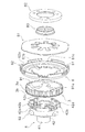
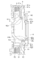
- FIG. 1 is a cross-sectional view of a clutch device according to an embodiment of the present invention.
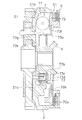
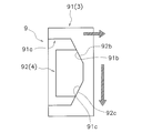
- FIG. 2 is an exploded perspective view of a part of the clutch device of FIG. 1. The figure which extracted a part of FIG. The figure which extracted the other part of FIG. The plane schematic diagram of a cam part.
- FIG. 1 is a cross-sectional view of a clutch device 1 for a motorcycle as an example of a power transmission device.
- the “axial direction” refers to the left-right direction in FIG. 1 (the right direction is the “first direction”, the left direction is the “second direction”), and the “axial direction outside” (the first direction side). ) Indicates the right side of FIG. 1, and “inner side in the axial direction” (second direction side) indicates the left side of FIG.
- This clutch device 1 is for transmitting the power from the crankshaft of the engine to the transmission and for canceling the power transmission state by operating the release mechanism.
- the clutch device 1 includes a clutch housing 2, a clutch hub 3 and a clutch center 4 that constitute an output member, a clutch portion 5, a first pressure plate 6 (first pressure member), a centrifugal pressing mechanism 7, and a release. And a mechanism 8.
- the clutch device 1 has a cam portion 9 (torque transmission portion) that transmits torque between the clutch hub 3 and the clutch center 4.
- the clutch housing 2 includes a disk portion 21 and a cylindrical portion 22 and is connected to the input gear 10.
- the input gear 10 meshes with a drive gear (not shown) on the engine side, and power (torque) generated by the engine (not shown) is input to the input gear 10.
- the disc portion 21 is formed with a plurality of protrusions 21a protruding inward in the axial direction at predetermined intervals in the circumferential direction.
- the elastic member 11 is mounted on the outer periphery of the protruding portion 21 a, and torque from the input gear 10 is transmitted to the disc portion 21 via the elastic member 11.
- the clutch housing 2 and the input gear 10 are connected in the axial direction via a plate 12 and a rivet 13.
- the cylindrical portion 22 is formed so as to extend outward from the outer peripheral edge of the disc portion 21 in the axial direction.
- a plurality of notches 22a extending in the axial direction are formed in the cylindrical portion 22 at predetermined intervals in the circumferential direction.
- the clutch hub 3 is disposed inside the clutch housing 2, specifically, on the inner peripheral side of the cylindrical portion 22. As shown in FIGS. 1 and 2, the clutch hub 3 is an annular member, and a plurality of engagement grooves 3a are formed on the outer peripheral surface. An engagement portion 3b that is annularly continuous is formed at the axially inner end of the engagement groove 3a. That is, the engagement groove 3a is open on the outer side in the axial direction, but is closed on the inner side in the axial direction.
- FIG. 2 is an exploded view showing a part of the clutch device 1.
- the clutch center 4 is arranged on the inner peripheral side of the clutch housing 2 and further on the inner peripheral side of the clutch hub 3.
- the clutch center 4 has a boss portion 41, a tubular portion 42, and a connecting portion 43.
- the boss portion 41 is formed in a cylindrical shape, and a spline hole 41a extending in the axial direction is formed on the inner peripheral surface. An input shaft (not shown) of the transmission is engaged with the spline hole 41a.
- the cylindrical portion 42 is formed on the outer peripheral portion of the clutch center 4 and is disposed so that a part of the axial direction overlaps the inner peripheral surface of the clutch hub 3 in the axial direction.
- the cylindrical portion 42 includes a plurality of engaging grooves 42a, three support portions 42b, and six fixing portions 42c.
- the engagement groove 42 a is formed at the outer end of the cylindrical portion 42 in the axial direction.
- the three support portions 42b are formed so as to protrude further from the outer peripheral surface of the cylindrical portion 42 to the outer peripheral side, and are arranged at equal intervals in the circumferential direction.
- a support protrusion 42d that protrudes outward in the axial direction is formed on the support portion 42b.
- the fixed portion 42c is formed so as to protrude axially outward from the axially outer end surface of the cylindrical portion 42.
- a screw hole 42e is formed in the fixing portion 42c.
- the connecting portion 43 is a portion that connects the boss portion 41 and the tubular portion 42.
- the connecting portion 43 is inclined so as to go outward in the axial direction from the inner peripheral side to the outer peripheral side.
- a thrust plate 14 is provided between the axially inner end surface of the boss portion 41 and the central portion of the input gear 10.
- the clutch unit 5 includes four first clutch plates 51 and three second clutch plates 52. Both the clutch plates 51 and 52 are formed in an annular shape and are alternately arranged in the axial direction.
- a plurality of engaging protrusions protruding outward are formed on the outer peripheral portion of the first clutch plate 51, and the engaging protrusions are engaged with notches 22 a formed in the cylindrical portion 22 of the clutch housing 2. . Accordingly, the first clutch plate 51 is movable in the axial direction with respect to the clutch housing 2 and is not relatively rotatable. The first clutch plate 51 has friction facings fixed on both sides.
- the second clutch plate 52 is formed with a plurality of engaging protrusions that protrude toward the inner peripheral side at the inner peripheral end.
- the engaging protrusion is engaged with an engaging groove 3 a formed on the outer peripheral surface of the clutch hub 3. Therefore, the second clutch plate 52 is movable in the axial direction with respect to the clutch hub 3 and is not relatively rotatable.
- the first pressure plate 6 As shown in FIGS. 2 and 3, the first pressure plate 6 includes a main body portion 61 and a cylindrical portion 62.
- the main body 61 is an annular member, and a pressing surface 61a is formed on the outer peripheral portion of the side surface on the inner side in the axial direction.
- the pressing surface 61 a contacts the first clutch plate 51.
- a plurality of engaging protrusions 61 b are formed on the inner peripheral end of the main body 61.
- the engagement protrusion 61 b is engaged with the engagement groove 42 a of the clutch center 4. Therefore, the pressure plate 6 is movable in the axial direction with respect to the clutch center 4 in a predetermined range (a range in which the engagement groove 42a is formed) in the axial direction, and is not rotatable.
- a support protrusion 61 c is formed on the outer peripheral portion of the side surface on the outer side in the axial direction of the main body 61.
- the cylindrical portion 62 is formed to extend outward in the axial direction from the outer peripheral end portion of the main body portion 61.
- a plurality of engaging grooves 62 a are formed in the cylindrical portion 62.
- the centrifugal pressing mechanism 7 includes a weight member (centrifuge) 71, a second pressure plate 72 (second pressure member), and a pressing force adjustment mechanism 73.
- a plurality of grooves 21b extending in the radial direction are formed in the disk portion 21 of the clutch housing 2, and the weight member 71 is movable in the radial direction along the grooves 21b.
- the bottom surface of the groove 21b is inclined so as to go outward in the axial direction as it goes outward in the radial direction. Accordingly, when the weight member 71 moves outward in the radial direction, the weight member 71 also moves outward in the axial direction.
- the second pressure plate 72 is disposed between the weight member 71 and the clutch portion 5 (specifically, the first clutch plate 51) in the axial direction.
- the press surface 72a is formed in the outer peripheral part
- the engaging part 72b is formed in the inner peripheral part in the side surface of the axial direction outer side. The pressing surface 72 a can contact the first clutch plate 51.
- the pressing force adjusting mechanism 73 includes an engagement plate 73a, a plurality of springs 73b, a support plate 73c, and a plurality of bolts 73d.
- the engaging plate 73a has an inner peripheral disc portion 73e, an outer peripheral disc portion 73f, and a cylindrical portion 73g.
- a plurality of holes are formed in the inner peripheral disk portion 73e, and the support protrusions 21c of the clutch housing 2 pass through the holes.
- the support protrusion 21 c is formed on the disc portion 21 of the clutch housing 2 so as to protrude outward in the axial direction.
- the outer peripheral disc portion 73 f is engaged with the engaging portion 72 b of the second pressure plate 72.
- the plurality of springs 73b are mounted on the outer peripheral portion of the support protrusion 21c. One end of the spring 73b is supported by the inner peripheral disk portion 73e of the engagement plate 73a, and the other end is supported by the support plate 73c.
- the support plate 73c is fixed to the front end surface of the support protrusion 21c by a bolt 73d.
- the second pressure plate 72 is urged inward in the axial direction via the engagement plate 73a by the urging force of the spring 73b. That is, the second pressure plate 72 is urged in the direction opposite to the pressing force by the weight member 71 by the spring 73b. Therefore, by adjusting the urging force of the spring 73b, it is possible to adjust the pressing force applied to the clutch portion 5 by the weight member 71.
- the release mechanism 8 includes a diaphragm spring 81, a full clam ring 82, and a release plate 83.
- the diaphragm spring 81 includes an annular pressing portion 81a formed on the outer peripheral portion, a lever portion 81b including a plurality of levers formed on the inner peripheral portion, and a radial intermediate between the pressing portion 81a and the lever portion 81b. And a fulcrum part 81c formed in the part.
- the pressing portion 81 a is supported by the support protrusion 61 c of the first pressure plate 6 and can press the first pressure plate 6.
- the full clam ring 82 is formed in an annular shape and is fixed to the fixing portion 42 c of the cylindrical portion 42 of the clutch center 4 by a bolt 85.
- a support protrusion 82 a that protrudes inward in the axial direction is formed on the outer periphery of the full clam ring 82.
- a fulcrum portion 81 c of the diaphragm spring 81 is supported between the support protrusion 82 a and the support protrusion 42 d of the clutch center 4.
- an engagement recess 82b that is recessed in an annular shape is formed on the inner surface in the axial direction.
- the release plate 83 is formed in an annular shape and is disposed on the inner peripheral portion of the full clam ring 82.
- a pressing protrusion 83 a protruding in the axial direction is formed on the inner surface in the axial direction of the release plate 83.
- the pressing protrusion 83 a is in contact with the inner peripheral end portion of the lever portion 81 b of the diaphragm spring 81.
- an engaging portion 83b that engages with the engaging recess 82b of the full clam ring 82 is formed, and a guide portion 83c that extends in the axial direction is further formed.
- the guide portion 83 c is movable in the axial direction along the inner peripheral surface of the full clam ring 82.
- a release bearing (not shown) is mounted on the release plate 83. At the time of release, the release plate 83 is moved inward in the axial direction via a bearing.
- the cam portion 9 transmits torque between the clutch hub 3 and the clutch center 4. 2 and 5, the cam portion 9 includes a plurality of (three in the present embodiment) first cam portions 91 provided in the clutch hub 3 and a plurality of cam portions 9 provided in the clutch center 4 (this embodiment). 3) in the form.
- FIG. 5 is a schematic plan view of the cam portion 9 (viewed from the outer peripheral side).
- the first cam portion 91 is formed on the inner peripheral surface of the clutch hub 3 so as to protrude further to the inner peripheral side.
- the first cam portion 91 is formed with a cam recess 91a that is recessed toward the outer peripheral side.
- the cam recess 91a is opened inward in the axial direction, and a first cam surface 91b for transmitting positive torque and a second cam surface 91c for transmitting negative torque are formed on the outer side in the axial direction.
- Each of the cam surfaces 91b and 91c is inclined so as to be directed inward in the axial direction as the cam surfaces 91b and 91c are separated from the circumferential center of the cam recess 91a.
- the second cam portion 92 is formed on the outer peripheral surface of the cylindrical portion 42 of the clutch center 4 so as to protrude further to the outer peripheral side.
- a third cam surface 92b for forward rotation torque transmission and a fourth cam surface 92c for reverse rotation torque transmission are formed on the axially outer surface of the second cam portion 92.
- the third cam surface 92b has the same inclination as the first cam surface 91b of the clutch hub 3, and both 91b and 92b are in contact with each other.
- the fourth cam surface 92c has the same inclination as the second cam surface 91c of the clutch hub 3, and both 91c and 92c are in contact with each other.
- the assist cam portion described above is formed with an inclined cam surface, when torque is transmitted between the clutch hub and the clutch center, the magnitude is in accordance with the magnitude of the transmitted torque.
- the pressing force can be applied to the clutch portion 5.
- the cell motor for starting the engine is not provided. Therefore, the engine is started by kicking the kick pedal.
- the release force at the time of release is received by the clutch center 4.
- the member that receives the release force may be another member as long as the pressing force by the weight member 71 is not applied. Good.
- the configuration for transmitting the pressing force of the weight member to the clutch portion is not limited to the above embodiment.
- the pressing force adjustment mechanism may be omitted.
- the release force may be applied to the first pressure plate by using the lever principle by using another lever member or the like.
- the cam portion is formed integrally with the clutch hub and the clutch center, but may be constituted by another member.
- the power transmission device of the present invention it is possible to suppress the generation of drag torque during the release operation in a device that turns on the clutch portion by a pressing mechanism using a centrifuge.
Abstract
Provided is a power transmission device in which a clutch is turned on by a centrifugal pressing mechanism, said device suppressing drag torque during a release operation. This device includes a clutch hub (3), a clutch center (4), a clutch part (5), a first pressure plate (6), a centrifugal pressing mechanism (7), and a release mechanism (8). The first pressure plate (6) is disposed axially outward of the clutch part (5), and has a pressing part that presses the clutch part (5). The centrifugal pressing mechanism (7) is disposed axially inward of the clutch part (5), and has a weight member (71). The movement of the weight member (71) presses the clutch part (5) against the first pressure plate (6). The weight member (71) applies a releasing force to the clutch center (4) so as to move the pressing part of the first pressure plate (6) axially outward, whereby the release mechanism (8) cuts off power transmission to the clutch part (5).
Description
本発明は、動力伝達装置、特に、自動二輪車に設けられる動力伝達装置に関する。
The present invention relates to a power transmission device, and more particularly to a power transmission device provided in a motorcycle.
一般に、自動二輪車等に設けられる動力伝達装置として、多板クラッチ装置が用いられている。この多板クラッチ装置は、エンジンのクランク軸側に連結されるクラッチハウジングと、トランスミッション側に連結されるクラッチセンタと、それらの間で動力の伝達、遮断を行うためのクラッチ部と、クラッチ部を押圧するためのプレッシャプレートと、を有している。クラッチ部は、クラッチハウジングに係合する第1クラッチプレートと、クラッチセンタに係合する第2クラッチプレートと、を有しており、両クラッチプレートは軸方向に交互に配置されている。
Generally, a multi-plate clutch device is used as a power transmission device provided in a motorcycle or the like. The multi-plate clutch device includes a clutch housing connected to the crankshaft side of the engine, a clutch center connected to the transmission side, a clutch portion for transmitting and shutting power between them, and a clutch portion. And a pressure plate for pressing. The clutch portion has a first clutch plate that engages with the clutch housing and a second clutch plate that engages with the clutch center, and both clutch plates are alternately arranged in the axial direction.
また、従来の自動二輪車用の動力伝達装置として、遠心子としてのウェイト部材の遠心力を利用した多板クラッチ装置も提供されている(特許文献1)。この動力伝達装置は、クラッチハウジングの内部に形成された溝部にウェイト部材が配置されている。そして、クラッチハウジングが回転すると、内部に収容されたウェイト部材が、遠心力を受けて溝部に沿って径方向外方に移動するとともに軸方向にも移動する。このウェイト部材の軸方向の移動によって、第1,第2板材、及びコイルスプリングを介してプレッシャ部材が軸方向に押圧され、複数のクラッチプレートが圧接されてクラッチ部がオン(動力伝達状態)になる。
Also, as a conventional power transmission device for a motorcycle, a multi-plate clutch device using a centrifugal force of a weight member as a centrifuge is also provided (Patent Document 1). In this power transmission device, a weight member is disposed in a groove formed inside the clutch housing. When the clutch housing rotates, the weight member accommodated therein receives a centrifugal force and moves radially outward along the groove and also moves in the axial direction. By the movement of the weight member in the axial direction, the pressure member is pressed in the axial direction via the first and second plate members and the coil spring, the plurality of clutch plates are pressed, and the clutch portion is turned on (power transmission state). Become.
特許文献1の装置では、クラッチ部を挟んで、ウェイト部材やプレッシャ部材とは逆側にレリーズ機構が設けられている。そして、クラッチ部をオフ(動力伝達の解除状態)する場合は、レリーズ機構によってプレッシャ部材をウェイト部材側に押圧する。これにより、クラッチ部に対するプレッシャ部材の押圧力が解除され、クラッチ部はオフになる。
In the device of Patent Document 1, a release mechanism is provided on the opposite side of the weight member and the pressure member with the clutch portion interposed therebetween. When the clutch portion is turned off (power transmission is released), the pressure member is pressed toward the weight member by the release mechanism. Thereby, the pressing force of the pressure member against the clutch portion is released, and the clutch portion is turned off.
以上のようなレリーズ作動時において、プレッシャ部材をウェイト部材側に押圧する際に、第1板材はウェイト部材からクラッチ部側への押圧力を受け、第2板材はレリーズ機構から逆方向の押圧力を受けることになる。そして、第1板材と第2板材とは摩擦材を介して当接しているので、レリーズ作動時に第1板材と第2板材との間にドラグトルクが発生する。第2板材はクラッチセンタに係合しているので、ドラグトルクはクラッチセンタを介してトランスミッション側に伝達される。すると、トランスミッションのドグクラッチにトルクが作用し、このためドグクラッチの噛み合いを解除することが困難になる。
During the release operation as described above, when the pressure member is pressed toward the weight member, the first plate member receives a pressing force from the weight member toward the clutch portion, and the second plate member receives a pressing force in the reverse direction from the release mechanism. Will receive. And since the 1st board | plate material and the 2nd board | plate material are contact | abutted via the friction material, drag torque generate | occur | produces between a 1st board | plate material and a 2nd board | plate material at the time of release operation | movement. Since the second plate is engaged with the clutch center, the drag torque is transmitted to the transmission side via the clutch center. Then, torque acts on the dog clutch of the transmission, and it becomes difficult to release the engagement of the dog clutch.
本発明の課題は、遠心子を用いた押圧機構によってクラッチ部をオンする動力伝達装置において、レリーズ作動時のドラグトルクの発生を抑えることにある。
An object of the present invention is to suppress the generation of drag torque during a release operation in a power transmission device that turns on a clutch portion by a pressing mechanism using a centrifuge.
(1)本発明に係る動力伝達装置は、クラッチハウジングと、出力部材と、クラッチ部と、第1プレッシャ部材と、遠心式押圧機構と、レリーズ機構と、を備えている。クラッチハウジングはエンジンからの動力により回転する。出力部材は、クラッチハウジングの内周部に配置され、トランスミッション側の部材に動力を出力する。クラッチ部はクラッチハウジングと出力部材との間で動力の伝達を行う。第1プレッシャ部材は、クラッチ部の軸方向の第1方向側に配置され、クラッチ部を押圧可能な押圧部を有する。遠心式押圧機構は、クラッチ部の軸方向の第2方向側に配置され、クラッチハウジングの回転により径方向及び軸方向に移動可能な遠心子を有し、遠心子の移動によりクラッチ部を第1プレッシャ部材の押圧部に対して押圧する。レリーズ機構は、遠心子によって押圧力を受ける部分以外の部分にレリーズ力を作用させることにより第1プレッシャ部材の押圧部を第1方向に移動させ、クラッチ部の動力伝達を解除する。
(1) A power transmission device according to the present invention includes a clutch housing, an output member, a clutch portion, a first pressure member, a centrifugal pressing mechanism, and a release mechanism. The clutch housing is rotated by power from the engine. The output member is disposed on the inner peripheral portion of the clutch housing and outputs power to a member on the transmission side. The clutch portion transmits power between the clutch housing and the output member. A 1st pressure member is arrange | positioned at the 1st direction side of the axial direction of a clutch part, and has a press part which can press a clutch part. The centrifugal pressing mechanism is disposed on the second direction side in the axial direction of the clutch portion, has a centrifuge that can move in the radial direction and the axial direction by rotation of the clutch housing, and the first clutch portion is moved by the movement of the centrifuge. Press against the pressing part of the pressure member. The release mechanism moves the pressing portion of the first pressure member in the first direction by applying a release force to a portion other than the portion receiving the pressing force by the centrifuge, and releases the power transmission of the clutch portion.
この装置では、エンジンからの回転が伝達されてクラッチハウジングが回転すると、この回転によって遠心子が遠心力により径方向外方に移動するとともに、軸方向に移動する。この遠心子の軸方向の移動によって、クラッチ部は第1プレッシャ部材側に押圧され、クラッチ部はオンになる。
In this device, when the rotation from the engine is transmitted and the clutch housing rotates, the rotation causes the centrifuge to move outward in the radial direction by the centrifugal force and also to move in the axial direction. By the movement of the centrifuge in the axial direction, the clutch portion is pressed toward the first pressure member, and the clutch portion is turned on.
一方、レリーズ時には、レリーズ機構によって、第1プレッシャ部材の押圧部がクラッチから離れる第1方向に移動させられる。これにより、クラッチ部はオフになる。このとき、レリーズ機構によるレリーズ力は、遠心子によって押圧力を受ける部分以外の部分に作用する。したがって、遠心子による押圧力とレリーズ力によって回転部材がドラグトルクを発生することはない。このため、従来装置のような、ドラグトルクによる弊害を抑える事ができる。
On the other hand, at the time of release, the release mechanism moves the pressing portion of the first pressure member in the first direction away from the clutch. As a result, the clutch portion is turned off. At this time, the release force by the release mechanism acts on a portion other than the portion that receives the pressing force by the centrifuge. Therefore, the rotating member does not generate drag torque due to the pressing force and release force by the centrifuge. For this reason, the bad influence by drag torque like the conventional apparatus can be suppressed.
(2)好ましくは、遠心式押圧機構は、第2プレッシャ部材をさらに有している。第2プレッシャ部材は、遠心子とクラッチ部との軸方向間に配置され、遠心子の移動によってクラッチ部を第1方向に押圧する。
(2) Preferably, the centrifugal pressing mechanism further includes a second pressure member. A 2nd pressure member is arrange | positioned between the axial direction of a centrifuge and a clutch part, and presses a clutch part in a 1st direction by the movement of a centrifuge.
ここでは、遠心子によってクラッチ部が直接押圧されるのではなく、第2プレッシャ部材を介してクラッチ部が押圧される。このため、遠心子による押圧力は、クラッチ部に対して均一に安定して作用する。
Here, the clutch portion is not pressed directly by the centrifuge, but the clutch portion is pressed via the second pressure member. For this reason, the pressing force by the centrifuge acts uniformly and stably on the clutch portion.
(3)好ましくは、レリーズ機構は、円板状スプリングと、レリーズプレートと、を有している。円板状スプリングは、外周部に押圧部を有するとともに、径方向の中間部に支点部を有する。レリーズプレートは、円板状スプリングの内周部を第2方向に向かって押圧し、支点部を支点として円板状スプリングの外周部を第1方向に移動させる。
(3) Preferably, the release mechanism has a disk-shaped spring and a release plate. The disc-shaped spring has a pressing portion at the outer peripheral portion and a fulcrum portion at a radially intermediate portion. The release plate presses the inner peripheral portion of the disc-shaped spring toward the second direction, and moves the outer peripheral portion of the disc-shaped spring in the first direction with the fulcrum portion as a fulcrum.
ここでは、円板状スプリングを用いてクラッチ部を押圧している。また、レリーズ作動時には、てこの原理によってクラッチ部への押圧力を解除することができる。したがって、レリーズ機構の構成が簡単になる。
Here, the clutch part is pressed using a disk-shaped spring. Further, during the release operation, the pressing force to the clutch portion can be released by the lever principle. Therefore, the structure of the release mechanism is simplified.
(4)好ましくは、円板状スプリングの支点部は、出力部材に支持されている。出力部材は、遠心子による押圧力を受けない。このため、レリーズ機構のレリーズ力が出力部材に作用しても、遠心子の押圧力とレリーズ力によるドラグトルクが出力部材に発生することはない。
(4) Preferably, the fulcrum portion of the disc spring is supported by the output member. The output member is not subjected to a pressing force by the centrifuge. For this reason, even if the release force of the release mechanism acts on the output member, drag torque due to the pressing force of the centrifuge and the release force does not occur in the output member.
(5)好ましくは、クラッチ部は、クラッチハウジングに係合する第1クラッチプレートと、出力部材に係合する第2クラッチプレートと、を有している。そして、出力部材は、クラッチハブと、クラッチセンタと、トルク伝達部と、を有している。クラッチハブは第2クラッチプレートが係合する。クラッチセンタはトランスミッション側の部材に連結される。トルク伝達部はクラッチハブとクラッチセンタとの間でトルクを伝達する。
(5) Preferably, the clutch part has a first clutch plate that engages with the clutch housing and a second clutch plate that engages with the output member. And the output member has a clutch hub, a clutch center, and a torque transmission part. The clutch hub engages with the second clutch plate. The clutch center is connected to a member on the transmission side. The torque transmission unit transmits torque between the clutch hub and the clutch center.
ここでは、出力部材が、クラッチ部の出力部に係合するクラッチハブと、トランスミッション側の部材に連結されるクラッチセンタと、によって構成されている。
Here, the output member is composed of a clutch hub that engages with the output portion of the clutch portion, and a clutch center that is connected to a member on the transmission side.
(6)好ましくは、トルク伝達部は、クラッチセンタからクラッチハブにトルクが伝達される際に第1クラッチと第2クラッチプレートとの間に押圧力を付与する逆トルクアシストカム部を有する。
(6) Preferably, the torque transmission unit includes a reverse torque assist cam unit that applies a pressing force between the first clutch and the second clutch plate when torque is transmitted from the clutch center to the clutch hub.
ここでは、トルク伝達部によって、クラッチハブからクラッチセンタ、すなわち、入力側から出力側への正転トルクが伝達される。一方、クラッチセンタからクラッチハブに逆転トルクが伝達された際には、逆トルクアシストカム部によって、クラッチ部に対する押圧力が付与される。
Here, the torque transmission unit transmits the forward rotation torque from the clutch hub to the clutch center, that is, from the input side to the output side. On the other hand, when reverse torque is transmitted from the clutch center to the clutch hub, a pressing force is applied to the clutch portion by the reverse torque assist cam portion.
このため、始動時において、トランスミッション側の回転部材をキック操作によって回転させ、この回転を、クラッチ部を介してエンジン側に伝達し、エンジンを始動させることができる。
Therefore, at the time of starting, the rotation member on the transmission side can be rotated by a kick operation, and this rotation can be transmitted to the engine side via the clutch portion to start the engine.
(7)好ましくは、トルク伝達部は、クラッチハブからクラッチセンタにトルクが伝達される際に第1クラッチと第2クラッチプレートとの間に押圧力を付与する正トルクアシストカム部をさらに有する。
(7) Preferably, the torque transmission unit further includes a positive torque assist cam unit that applies a pressing force between the first clutch and the second clutch plate when torque is transmitted from the clutch hub to the clutch center.
ここでは、トルク伝達部によって、クラッチハブからクラッチセンタ、すなわち、入力側から出力側への正転トルクが伝達される。これに加えて、正転トルク伝達時には、正トルクアシストカム部によって、クラッチ部に対する押圧力が付与される。
Here, the torque transmission unit transmits the forward rotation torque from the clutch hub to the clutch center, that is, from the input side to the output side. In addition to this, when the forward rotation torque is transmitted, the positive torque assist cam portion applies a pressing force to the clutch portion.
このため、クラッチ部を複数のクラッチプレートによって構成する場合、少ない枚数のクラッチプレートで必要なトルク伝達容量を確保することができる。
For this reason, when the clutch portion is constituted by a plurality of clutch plates, a necessary torque transmission capacity can be ensured with a small number of clutch plates.
以上のような本発明では、遠心子を用いた押圧機構によってクラッチ部をオンする動力伝達装置において、レリーズ作動時のドラグトルクの発生を抑えることができる。
In the present invention as described above, in the power transmission device that turns on the clutch portion by the pressing mechanism using the centrifuge, it is possible to suppress the generation of drag torque during the release operation.
図1は、動力伝達装置の一例としての自動二輪車用のクラッチ装置1の断面図である。なお、以下の説明において、「軸方向」とは図1の左右方向(右方向が「第1方向」、左方向が「第2方向」)を示し、「軸方向外側」(第1方向側)とは図1の右側を示し、「軸方向内側」(第2方向側)とは図1の左側を示す。
FIG. 1 is a cross-sectional view of a clutch device 1 for a motorcycle as an example of a power transmission device. In the following description, the “axial direction” refers to the left-right direction in FIG. 1 (the right direction is the “first direction”, the left direction is the “second direction”), and the “axial direction outside” (the first direction side). ) Indicates the right side of FIG. 1, and “inner side in the axial direction” (second direction side) indicates the left side of FIG.
このクラッチ装置1は、エンジンのクランク軸からの動力をトランスミッションに伝達するとともに、レリーズ機構の操作によって動力伝達状態を解除するためのものである。クラッチ装置1は、クラッチハウジング2と、出力部材を構成するクラッチハブ3及びクラッチセンタ4と、クラッチ部5と、第1プレッシャプレート6(第1プレッシャ部材)と、遠心式押圧機構7と、レリーズ機構8と、を備えている。また、クラッチ装置1は、クラッチハブ3とクラッチセンタ4との間でトルクを伝達するカム部9(トルク伝達部)を有している。
This clutch device 1 is for transmitting the power from the crankshaft of the engine to the transmission and for canceling the power transmission state by operating the release mechanism. The clutch device 1 includes a clutch housing 2, a clutch hub 3 and a clutch center 4 that constitute an output member, a clutch portion 5, a first pressure plate 6 (first pressure member), a centrifugal pressing mechanism 7, and a release. And a mechanism 8. The clutch device 1 has a cam portion 9 (torque transmission portion) that transmits torque between the clutch hub 3 and the clutch center 4.
[クラッチハウジング2]
クラッチハウジング2は、円板部21及び筒状部22を備え、入力ギア10に連結されている。入力ギア10はエンジン側の駆動ギア(図示せず)に噛み合っており、この入力ギア10にエンジン(図示せず)で発生した動力(トルク)が入力される。 [Clutch housing 2]
Theclutch housing 2 includes a disk portion 21 and a cylindrical portion 22 and is connected to the input gear 10. The input gear 10 meshes with a drive gear (not shown) on the engine side, and power (torque) generated by the engine (not shown) is input to the input gear 10.
クラッチハウジング2は、円板部21及び筒状部22を備え、入力ギア10に連結されている。入力ギア10はエンジン側の駆動ギア(図示せず)に噛み合っており、この入力ギア10にエンジン(図示せず)で発生した動力(トルク)が入力される。 [Clutch housing 2]
The
円板部21には、軸方向内側に突出する複数の突起部21aが円周方向に所定の間隔で形成されている。突起部21aの外周には弾性部材11が装着されており、入力ギア10からのトルクは弾性部材11を介して円板部21に伝達される。クラッチハウジング2と入力ギア10とは、プレート12及びリベット13を介して軸方向に連結されている。
The disc portion 21 is formed with a plurality of protrusions 21a protruding inward in the axial direction at predetermined intervals in the circumferential direction. The elastic member 11 is mounted on the outer periphery of the protruding portion 21 a, and torque from the input gear 10 is transmitted to the disc portion 21 via the elastic member 11. The clutch housing 2 and the input gear 10 are connected in the axial direction via a plate 12 and a rivet 13.
筒状部22は、円板部21の外周縁から軸方向外側に延びるように形成されている。この筒状部22には、軸方向に延びる複数の切欠き22aが円周方向に所定の間隔で形成されている。
The cylindrical portion 22 is formed so as to extend outward from the outer peripheral edge of the disc portion 21 in the axial direction. A plurality of notches 22a extending in the axial direction are formed in the cylindrical portion 22 at predetermined intervals in the circumferential direction.
[クラッチハブ3]
クラッチハブ3は、クラッチハウジング2の内部、詳細には筒状部22の内周側に配置されている。図1及び図2に示すように、クラッチハブ3は環状の部材であり、外周面には複数の係合溝3aが形成されている。なお、係合溝3aの軸方向内側端には、環状に連続する係合部3bが形成されている。すなわち、係合溝3aは軸方向外側には開放しているが、軸方向内側は閉じられている。なお、図2は、クラッチ装置1の一部を分解して示す図である。 [Clutch hub 3]
Theclutch hub 3 is disposed inside the clutch housing 2, specifically, on the inner peripheral side of the cylindrical portion 22. As shown in FIGS. 1 and 2, the clutch hub 3 is an annular member, and a plurality of engagement grooves 3a are formed on the outer peripheral surface. An engagement portion 3b that is annularly continuous is formed at the axially inner end of the engagement groove 3a. That is, the engagement groove 3a is open on the outer side in the axial direction, but is closed on the inner side in the axial direction. FIG. 2 is an exploded view showing a part of the clutch device 1.
クラッチハブ3は、クラッチハウジング2の内部、詳細には筒状部22の内周側に配置されている。図1及び図2に示すように、クラッチハブ3は環状の部材であり、外周面には複数の係合溝3aが形成されている。なお、係合溝3aの軸方向内側端には、環状に連続する係合部3bが形成されている。すなわち、係合溝3aは軸方向外側には開放しているが、軸方向内側は閉じられている。なお、図2は、クラッチ装置1の一部を分解して示す図である。 [Clutch hub 3]
The
[クラッチセンタ4]
クラッチセンタ4は、クラッチハウジング2の内周部で、クラッチハブ3のさらに内周側に配置されている。クラッチセンタ4は、ボス部41と、筒状部42と、連結部43と、を有している。 [Clutch center 4]
Theclutch center 4 is arranged on the inner peripheral side of the clutch housing 2 and further on the inner peripheral side of the clutch hub 3. The clutch center 4 has a boss portion 41, a tubular portion 42, and a connecting portion 43.
クラッチセンタ4は、クラッチハウジング2の内周部で、クラッチハブ3のさらに内周側に配置されている。クラッチセンタ4は、ボス部41と、筒状部42と、連結部43と、を有している。 [Clutch center 4]
The
ボス部41は、筒状に形成され、内周面には軸方向に延びるスプライン孔41aが形成されている。このスプライン孔41aには、トランスミッションの入力軸(図示せず)が係合する。
The boss portion 41 is formed in a cylindrical shape, and a spline hole 41a extending in the axial direction is formed on the inner peripheral surface. An input shaft (not shown) of the transmission is engaged with the spline hole 41a.
筒状部42は、クラッチセンタ4の外周部に形成され、軸方向の一部がクラッチハブ3の内周面と軸方向に重なるように配置されている。また、筒状部42は、複数の係合溝42aと、3つの支持部42bと、6つの固定部42cと、を有している。係合溝42aは、筒状部42の外周面の軸方向外側端部に形成されている。3つの支持部42bは、筒状部42の外周面からさらに外周側に突出して形成されており、円周方向に等間隔に配置されている。支持部42bには軸方向外側に突出する支持突起42dが形成されている。固定部42cは、筒状部42の軸方向外側の端面から軸方向外側に突出して形成されている。固定部42cにはネジ孔42eが形成されている。
The cylindrical portion 42 is formed on the outer peripheral portion of the clutch center 4 and is disposed so that a part of the axial direction overlaps the inner peripheral surface of the clutch hub 3 in the axial direction. The cylindrical portion 42 includes a plurality of engaging grooves 42a, three support portions 42b, and six fixing portions 42c. The engagement groove 42 a is formed at the outer end of the cylindrical portion 42 in the axial direction. The three support portions 42b are formed so as to protrude further from the outer peripheral surface of the cylindrical portion 42 to the outer peripheral side, and are arranged at equal intervals in the circumferential direction. A support protrusion 42d that protrudes outward in the axial direction is formed on the support portion 42b. The fixed portion 42c is formed so as to protrude axially outward from the axially outer end surface of the cylindrical portion 42. A screw hole 42e is formed in the fixing portion 42c.
連結部43は、ボス部41と筒状部42とを連結する部分である。連結部43は、内周側から外周側にかけて軸方向外側に向かうように傾斜している。
The connecting portion 43 is a portion that connects the boss portion 41 and the tubular portion 42. The connecting portion 43 is inclined so as to go outward in the axial direction from the inner peripheral side to the outer peripheral side.
なお、ボス部41の軸方向内側の端面と入力ギア10の中央部との間には、スラストプレート14が設けられている。
A thrust plate 14 is provided between the axially inner end surface of the boss portion 41 and the central portion of the input gear 10.
[クラッチ部5]
クラッチ部5は、4枚の第1クラッチプレート51と、3枚の第2クラッチプレート52と、を有している。これらの両クラッチプレート51,52はともに環状に形成されており、軸方向に交互に配置されている。 [Clutch part 5]
Theclutch unit 5 includes four first clutch plates 51 and three second clutch plates 52. Both the clutch plates 51 and 52 are formed in an annular shape and are alternately arranged in the axial direction.
クラッチ部5は、4枚の第1クラッチプレート51と、3枚の第2クラッチプレート52と、を有している。これらの両クラッチプレート51,52はともに環状に形成されており、軸方向に交互に配置されている。 [Clutch part 5]
The
第1クラッチプレート51の外周部には外周側に突出する複数の係合突起が形成されており、この係合突起がクラッチハウジング2の筒状部22に形成された切欠き22aに噛み合っている。したがって、第1クラッチプレート51は、クラッチハウジング2に対して、軸方向に移動自在であり、かつ相対回転不能である。第1クラッチプレート51には両面に摩擦フェーシングが固定されている。
A plurality of engaging protrusions protruding outward are formed on the outer peripheral portion of the first clutch plate 51, and the engaging protrusions are engaged with notches 22 a formed in the cylindrical portion 22 of the clutch housing 2. . Accordingly, the first clutch plate 51 is movable in the axial direction with respect to the clutch housing 2 and is not relatively rotatable. The first clutch plate 51 has friction facings fixed on both sides.
第2クラッチプレート52は、内周端部において内周側に突出する複数の係合突起が形成されている。この係合突起は、クラッチハブ3の外周面に形成された係合溝3aに噛み合っている。したがって、第2クラッチプレート52は、クラッチハブ3に対して、軸方向に移動自在であり、かつ相対回転不能である。
The second clutch plate 52 is formed with a plurality of engaging protrusions that protrude toward the inner peripheral side at the inner peripheral end. The engaging protrusion is engaged with an engaging groove 3 a formed on the outer peripheral surface of the clutch hub 3. Therefore, the second clutch plate 52 is movable in the axial direction with respect to the clutch hub 3 and is not relatively rotatable.
[第1プレッシャプレート6]
図2及び図3に示すように、第1プレッシャプレート6は、本体部61と、筒状部62と、を有している。 [First pressure plate 6]
As shown in FIGS. 2 and 3, thefirst pressure plate 6 includes a main body portion 61 and a cylindrical portion 62.
図2及び図3に示すように、第1プレッシャプレート6は、本体部61と、筒状部62と、を有している。 [First pressure plate 6]
As shown in FIGS. 2 and 3, the
本体部61は、環状の部材であって、軸方向内側の側面の外周部に押圧面61aが形成されている。この押圧面61aが第1クラッチプレート51に当接する。また、本体部61の内周端には、複数の係合突起61bが形成されている。この係合突起61bがクラッチセンタ4の係合溝42aに係合している。したがって、プレッシャプレート6は、クラッチセンタ4に対して、軸方向に所定の範囲(係合溝42aが形成された範囲)で軸方向に移動自在であり、かつ回転不能である。本体部61の軸方向外側の側面において、外周部には、支持突起61cが形成されている。
The main body 61 is an annular member, and a pressing surface 61a is formed on the outer peripheral portion of the side surface on the inner side in the axial direction. The pressing surface 61 a contacts the first clutch plate 51. A plurality of engaging protrusions 61 b are formed on the inner peripheral end of the main body 61. The engagement protrusion 61 b is engaged with the engagement groove 42 a of the clutch center 4. Therefore, the pressure plate 6 is movable in the axial direction with respect to the clutch center 4 in a predetermined range (a range in which the engagement groove 42a is formed) in the axial direction, and is not rotatable. A support protrusion 61 c is formed on the outer peripheral portion of the side surface on the outer side in the axial direction of the main body 61.
筒状部62は、本体部61の外周端部から軸方向外側に延びて形成されている。筒状部62には、複数の係合溝62aが形成されている。
The cylindrical portion 62 is formed to extend outward in the axial direction from the outer peripheral end portion of the main body portion 61. A plurality of engaging grooves 62 a are formed in the cylindrical portion 62.
[遠心式押圧機構7]
遠心式押圧機構7は、図4に示すように、ウェイト部材(遠心子)71と、第2プレッシャプレート72(第2プレッシャ部材)と、押圧力調整機構73と、を有している。 [Centrifuge pressing mechanism 7]
As shown in FIG. 4, the centrifugalpressing mechanism 7 includes a weight member (centrifuge) 71, a second pressure plate 72 (second pressure member), and a pressing force adjustment mechanism 73.
遠心式押圧機構7は、図4に示すように、ウェイト部材(遠心子)71と、第2プレッシャプレート72(第2プレッシャ部材)と、押圧力調整機構73と、を有している。 [Centrifuge pressing mechanism 7]
As shown in FIG. 4, the centrifugal
クラッチハウジング2の円板部21には、径方向に延びる複数の溝21bが形成されており、この溝21bに沿ってウェイト部材71は径方向移動自在である。また、溝21bの底面は、図1,4に示されるように、径方向外方に行くに従って軸方向外側に向かうように傾斜している。したがって、ウェイト部材71が径方向外方に移動すると、ウェイト部材71は軸方向外側にも移動することになる。
A plurality of grooves 21b extending in the radial direction are formed in the disk portion 21 of the clutch housing 2, and the weight member 71 is movable in the radial direction along the grooves 21b. As shown in FIGS. 1 and 4, the bottom surface of the groove 21b is inclined so as to go outward in the axial direction as it goes outward in the radial direction. Accordingly, when the weight member 71 moves outward in the radial direction, the weight member 71 also moves outward in the axial direction.
第2プレッシャプレート72は、ウェイト部材71とクラッチ部5(詳細には第1クラッチプレート51)との軸方向間に配置されている。第2プレッシャプレート72は、軸方向外側の側面において、外周部には押圧面72aが形成され、内周部には係合部72bが形成されている。押圧面72aは第1クラッチプレート51に当接可能である。
The second pressure plate 72 is disposed between the weight member 71 and the clutch portion 5 (specifically, the first clutch plate 51) in the axial direction. As for the 2nd pressure plate 72, the press surface 72a is formed in the outer peripheral part, and the engaging part 72b is formed in the inner peripheral part in the side surface of the axial direction outer side. The pressing surface 72 a can contact the first clutch plate 51.
押圧力調整機構73は、係合プレート73aと、複数のスプリング73bと、支持プレート73cと、複数のボルト73dと、を有している。
The pressing force adjusting mechanism 73 includes an engagement plate 73a, a plurality of springs 73b, a support plate 73c, and a plurality of bolts 73d.
係合プレート73aは、内周円板部73eと、外周円板部73fと、筒状部73gと、を有している。内周円板部73eには、複数の孔が形成されており、この孔を、クラッチハウジング2の支持突起21cが貫通している。支持突起21cは、クラッチハウジング2の円板部21に軸方向外側に突出するように形成されている。外周円板部73fは第2プレッシャプレート72の係合部72bに係合している。
The engaging plate 73a has an inner peripheral disc portion 73e, an outer peripheral disc portion 73f, and a cylindrical portion 73g. A plurality of holes are formed in the inner peripheral disk portion 73e, and the support protrusions 21c of the clutch housing 2 pass through the holes. The support protrusion 21 c is formed on the disc portion 21 of the clutch housing 2 so as to protrude outward in the axial direction. The outer peripheral disc portion 73 f is engaged with the engaging portion 72 b of the second pressure plate 72.
複数のスプリング73bは、支持突起21cの外周部に装着されている。スプリング73bの一端は係合プレート73aの内周円板部73eに支持され、他端は支持プレート73cに支持されている。支持プレート73cは、支持突起21cの先端面にボルト73dによって固定されている。
The plurality of springs 73b are mounted on the outer peripheral portion of the support protrusion 21c. One end of the spring 73b is supported by the inner peripheral disk portion 73e of the engagement plate 73a, and the other end is supported by the support plate 73c. The support plate 73c is fixed to the front end surface of the support protrusion 21c by a bolt 73d.
このような構成では、スプリング73bの付勢力によって係合プレート73aを介して第2プレッシャプレート72が軸方向内側に付勢される。すなわち、第2プレッシャプレート72は、スプリング73bによってウェイト部材71による押付力とは逆方向に付勢される。したがって、スプリング73bの付勢力を調整することによって、ウェイト部材71によるクラッチ部5への押圧力を調整することが可能になる。
In such a configuration, the second pressure plate 72 is urged inward in the axial direction via the engagement plate 73a by the urging force of the spring 73b. That is, the second pressure plate 72 is urged in the direction opposite to the pressing force by the weight member 71 by the spring 73b. Therefore, by adjusting the urging force of the spring 73b, it is possible to adjust the pressing force applied to the clutch portion 5 by the weight member 71.
[レリーズ機構8]
レリーズ機構8は、図3に示すように、ダイヤフラムスプリング81と、フルクラムリング82と、レリーズプレート83と、を有している。 [Release mechanism 8]
As shown in FIG. 3, therelease mechanism 8 includes a diaphragm spring 81, a full clam ring 82, and a release plate 83.
レリーズ機構8は、図3に示すように、ダイヤフラムスプリング81と、フルクラムリング82と、レリーズプレート83と、を有している。 [Release mechanism 8]
As shown in FIG. 3, the
ダイヤフラムスプリング81は、外周部に形成された環状の押圧部81aと、内周部に形成された複数のレバーからなるレバー部81bと、押圧部81aとレバー部81bとの間の径方向の中間部に形成された支点部81cと、を有する。押圧部81aは第1プレッシャプレート6の支持突起61cに支持されて第1プレッシャプレート6を押圧可能である。
The diaphragm spring 81 includes an annular pressing portion 81a formed on the outer peripheral portion, a lever portion 81b including a plurality of levers formed on the inner peripheral portion, and a radial intermediate between the pressing portion 81a and the lever portion 81b. And a fulcrum part 81c formed in the part. The pressing portion 81 a is supported by the support protrusion 61 c of the first pressure plate 6 and can press the first pressure plate 6.
フルクラムリング82は、環状に形成され、ボルト85によってクラッチセンタ4の筒状部42の固定部42cに固定されている。フルクラムリング82の外周部には、軸方向内側に突出する支持突起82aが形成されている。この支持突起82aとクラッチセンタ4の支持突起42dとの間に、ダイヤフラムスプリング81の支点部81cが支持されている。また、フルクラムリング82の内周端部において、軸方向内側の面には、環状に凹む係合凹部82bが形成されている。
The full clam ring 82 is formed in an annular shape and is fixed to the fixing portion 42 c of the cylindrical portion 42 of the clutch center 4 by a bolt 85. A support protrusion 82 a that protrudes inward in the axial direction is formed on the outer periphery of the full clam ring 82. A fulcrum portion 81 c of the diaphragm spring 81 is supported between the support protrusion 82 a and the support protrusion 42 d of the clutch center 4. Further, at the inner peripheral end of the full clam ring 82, an engagement recess 82b that is recessed in an annular shape is formed on the inner surface in the axial direction.
レリーズプレート83は、環状に形成され、フルクラムリング82の内周部に配置されている。レリーズプレート83の軸方向内側の面には、軸方向に突出する押圧用突起83aが形成されている。この押圧用突起83aがダイヤフラムスプリング81のレバー部81bの内周端部に当接している。また、レリーズプレート83の外周部には、フルクラムリング82の係合凹部82bに係合する係合部83bが形成され、さらに軸方向に延びるガイド部83cが形成されている。ガイド部83cは、フルクラムリング82の内周面に沿って軸方向に移動可能である。レリーズプレート83には、図示しないレリーズ用の軸受が装着されている。そして、レリーズ時には、レリーズプレート83は、軸受を介して軸方向内側に移動させられる。
The release plate 83 is formed in an annular shape and is disposed on the inner peripheral portion of the full clam ring 82. A pressing protrusion 83 a protruding in the axial direction is formed on the inner surface in the axial direction of the release plate 83. The pressing protrusion 83 a is in contact with the inner peripheral end portion of the lever portion 81 b of the diaphragm spring 81. Further, on the outer peripheral portion of the release plate 83, an engaging portion 83b that engages with the engaging recess 82b of the full clam ring 82 is formed, and a guide portion 83c that extends in the axial direction is further formed. The guide portion 83 c is movable in the axial direction along the inner peripheral surface of the full clam ring 82. A release bearing (not shown) is mounted on the release plate 83. At the time of release, the release plate 83 is moved inward in the axial direction via a bearing.
以上のような構成では、レリーズプレート83が軸方向内側に移動すると、ダイヤフラムスプリング81のレバー部81bの内周端部が軸方向内側に移動し、ダイヤフラムスプリング81は支点部81cを支点として押圧部81aが軸方向外側に移動する。すなわち、てこの原理によって、ダイヤフラムスプリング81の押圧部81aは軸方向外側に移動する。これにより、第1プレッシャプレート6のクラッチ部5への押圧力が解除される。
In the configuration as described above, when the release plate 83 moves inward in the axial direction, the inner peripheral end portion of the lever portion 81b of the diaphragm spring 81 moves inward in the axial direction, and the diaphragm spring 81 uses the fulcrum portion 81c as a fulcrum. 81a moves outward in the axial direction. That is, by the lever principle, the pressing portion 81a of the diaphragm spring 81 moves outward in the axial direction. Thereby, the pressing force to the clutch part 5 of the 1st pressure plate 6 is cancelled | released.
[カム部9]
カム部9は、クラッチハブ3とクラッチセンタ4との間でトルクを伝達する。カム部9は、図2及び図5に示すように、クラッチハブ3に設けられた複数(本実施形態では3個)の第1カム部91と、クラッチセンタ4に設けられた複数(本実施形態では3個)の第2カム部92と、を有している。なお、図5はカム部9の平面模式図(外周側から視た図)である。 [Cam part 9]
Thecam portion 9 transmits torque between the clutch hub 3 and the clutch center 4. 2 and 5, the cam portion 9 includes a plurality of (three in the present embodiment) first cam portions 91 provided in the clutch hub 3 and a plurality of cam portions 9 provided in the clutch center 4 (this embodiment). 3) in the form. FIG. 5 is a schematic plan view of the cam portion 9 (viewed from the outer peripheral side).
カム部9は、クラッチハブ3とクラッチセンタ4との間でトルクを伝達する。カム部9は、図2及び図5に示すように、クラッチハブ3に設けられた複数(本実施形態では3個)の第1カム部91と、クラッチセンタ4に設けられた複数(本実施形態では3個)の第2カム部92と、を有している。なお、図5はカム部9の平面模式図(外周側から視た図)である。 [Cam part 9]
The
第1カム部91は、クラッチハブ3の内周面において、さらに内周側に突出するように形成されている。第1カム部91には外周側に凹むカム凹部91aが形成されている。カム凹部91aは、軸方向内側に開放するとともに、軸方向外側には、正トルク伝達用の第1カム面91bと、負トルク伝達用の第2カム面91cと、が形成されている。各カム面91b,91cは、カム凹部91aの周方向の中央から離れるにしたがって軸方向内側に向かうように傾斜している。
The first cam portion 91 is formed on the inner peripheral surface of the clutch hub 3 so as to protrude further to the inner peripheral side. The first cam portion 91 is formed with a cam recess 91a that is recessed toward the outer peripheral side. The cam recess 91a is opened inward in the axial direction, and a first cam surface 91b for transmitting positive torque and a second cam surface 91c for transmitting negative torque are formed on the outer side in the axial direction. Each of the cam surfaces 91b and 91c is inclined so as to be directed inward in the axial direction as the cam surfaces 91b and 91c are separated from the circumferential center of the cam recess 91a.
第2カム部92は、クラッチセンタ4の筒状部42の外周面において、さらに外周側に突出するように形成されている。第2カム部92の軸方向外側の面には、正転トルク伝達用の第3カム面92bと、逆転トルク伝達用の第4カム面92cと、が形成されている。第3カム面92bは、クラッチハブ3の第1カム面91bと同じ傾斜であり、両者91b,92bは互いに当接している。また、第4カム面92cは、クラッチハブ3の第2カム面91cと同じ傾斜であり、両者91c,92cは互いに接触している。
The second cam portion 92 is formed on the outer peripheral surface of the cylindrical portion 42 of the clutch center 4 so as to protrude further to the outer peripheral side. A third cam surface 92b for forward rotation torque transmission and a fourth cam surface 92c for reverse rotation torque transmission are formed on the axially outer surface of the second cam portion 92. The third cam surface 92b has the same inclination as the first cam surface 91b of the clutch hub 3, and both 91b and 92b are in contact with each other. The fourth cam surface 92c has the same inclination as the second cam surface 91c of the clutch hub 3, and both 91c and 92c are in contact with each other.
このようなカム部9では、図5に示すように、クラッチハブ3からクラッチセンタ4にトルク(正転トルク)が伝達されると、第1カム面91bと第3カム面92bとが互いに押圧され、クラッチハブ3はクラッチセンタ4に対して軸方向外側に移動する。クラッチハブ3の外周面に形成された係合部3bは、3枚の第2クラッチプレート52のうちのもっとも軸方向内側の第2クラッチプレート52に係合しているので、これにより、第1クラッチプレート51と第2クラッチプレート52とがさらに強固に押圧されることになる。すなわち、第1カム面91bと第3カム面92bとによって、正転トルク伝達時にクラッチオンのためのアシスト力を発生する正転トルクアシストカム部が構成されている。
In such a cam portion 9, as shown in FIG. 5, when torque (forward rotation torque) is transmitted from the clutch hub 3 to the clutch center 4, the first cam surface 91b and the third cam surface 92b are pressed against each other. Then, the clutch hub 3 moves outward in the axial direction with respect to the clutch center 4. The engaging portion 3b formed on the outer peripheral surface of the clutch hub 3 is engaged with the second clutch plate 52 that is the innermost in the axial direction among the three second clutch plates 52. The clutch plate 51 and the second clutch plate 52 are pressed more firmly. That is, the first cam surface 91b and the third cam surface 92b constitute a forward rotation torque assist cam portion that generates an assist force for clutch-on when the forward rotation torque is transmitted.
また、逆にクラッチセンタ4からクラッチハブ3に同じ回転方向のトルク(逆転トルク)伝達されると、第2カム面91cと第4カム面92cとが互いに押圧され、クラッチハブ3はクラッチセンタ4に対して軸方向外側に移動する。このため、前記同様に、クラッチハブ3の係合部3bが第2クラッチプレート52を軸方向外側に移動させ、これにより、第1クラッチプレート51と第2クラッチプレート52とがさらに強固に押圧されることになる。すなわち、第2カム面91cと第4カム面92cとによって、逆転トルク伝達時にクラッチオンのためのアシスト力を発生する逆転トルクアシストカム部が構成されている。
Conversely, when torque in the same rotational direction (reverse torque) is transmitted from the clutch center 4 to the clutch hub 3, the second cam surface 91c and the fourth cam surface 92c are pressed against each other, and the clutch hub 3 Move outward in the axial direction. Therefore, similarly to the above, the engaging portion 3b of the clutch hub 3 moves the second clutch plate 52 outward in the axial direction, whereby the first clutch plate 51 and the second clutch plate 52 are pressed more firmly. Will be. That is, the second cam surface 91c and the fourth cam surface 92c constitute a reverse torque assist cam portion that generates an assist force for clutch-on when the reverse torque is transmitted.
なお、以上のアシストカム部では、傾斜するカム面で形成されているので、クラッチハブとクラッチセンタとの間でトルクが伝達される際には、伝達されるトルクの大きさに応じた大きさの押圧力をクラッチ部5に付与することができる。
Since the assist cam portion described above is formed with an inclined cam surface, when torque is transmitted between the clutch hub and the clutch center, the magnitude is in accordance with the magnitude of the transmitted torque. The pressing force can be applied to the clutch portion 5.
[動作]
<クラッチオン状態>
エンジンからの回転が本装置に入力され、クラッチのレリーズ操作がなされていない状態では、ウェイト部材71は、遠心力によって径方向外方かつ軸方向外側に移動する。このため、ウェイト部材71の軸方向外側への押圧力は、第2プレッシャプレート72を介してクラッチ部5に伝達される。一方、クラッチ部5を挟んで第2プレッシャプレート72の逆側には、第1プレッシャプレート6を介してダイヤフラムスプリング81の押圧力が作用しているので、クラッチ部5は両プレッシャプレート6,72間で挟持される。したがって、クラッチ部5はオン(動力伝達状態)となる。 [Operation]
<Clutch on state>
When the rotation from the engine is input to the apparatus and the clutch release operation is not performed, theweight member 71 moves radially outward and axially outward by centrifugal force. For this reason, the pressing force of the weight member 71 outward in the axial direction is transmitted to the clutch portion 5 via the second pressure plate 72. On the other hand, the pressing force of the diaphragm spring 81 acts on the opposite side of the second pressure plate 72 across the clutch portion 5 via the first pressure plate 6, so that the clutch portion 5 has both pressure plates 6, 72. Sandwiched between. Therefore, the clutch unit 5 is turned on (power transmission state).
<クラッチオン状態>
エンジンからの回転が本装置に入力され、クラッチのレリーズ操作がなされていない状態では、ウェイト部材71は、遠心力によって径方向外方かつ軸方向外側に移動する。このため、ウェイト部材71の軸方向外側への押圧力は、第2プレッシャプレート72を介してクラッチ部5に伝達される。一方、クラッチ部5を挟んで第2プレッシャプレート72の逆側には、第1プレッシャプレート6を介してダイヤフラムスプリング81の押圧力が作用しているので、クラッチ部5は両プレッシャプレート6,72間で挟持される。したがって、クラッチ部5はオン(動力伝達状態)となる。 [Operation]
<Clutch on state>
When the rotation from the engine is input to the apparatus and the clutch release operation is not performed, the
このような状態では、エンジンから入力ギア10及び弾性部材11を介して入力されたトルクは、クラッチハウジング2を介して第1及び第2クラッチプレート51,52に伝達され、さらにクラッチハブ3及びクラッチセンタ4を介してトランスミッションの入力軸(図示せず)に伝達される。
In such a state, torque input from the engine via the input gear 10 and the elastic member 11 is transmitted to the first and second clutch plates 51 and 52 via the clutch housing 2, and further, the clutch hub 3 and the clutch It is transmitted to the input shaft (not shown) of the transmission via the center 4.
ここで、クラッチハブ3からクラッチセンタ4にトルク(正転トルク)が伝達されると、前述のように、カム部9の作用によってクラッチハブ3を軸方向外側に移動させるアシスト力が作用する。このため、クラッチオンのための押圧力がさらに大きくなる。
Here, when torque (forward rotation torque) is transmitted from the clutch hub 3 to the clutch center 4, as described above, an assisting force for moving the clutch hub 3 outward in the axial direction is applied by the action of the cam portion 9. For this reason, the pressing force for clutch-on is further increased.
<レリーズ動作>
一方、ライダーの操作によってレリーズプレート83が軸方向内側に移動すると、前述のように、ダイヤフラムスプリング81の外周部(押圧部81a)が第1プレッシャプレート6から離れる方向に移動する。このため、ダイヤフラムスプリング81のクラッチ部5に対する押圧力が解除され、ウェイト部材71による押圧力もクラッチ部5に伝わらない。したがって、クラッチ部5はオフ(動力伝達状態の解除)になる。 <Release operation>
On the other hand, when therelease plate 83 is moved inward in the axial direction by the rider's operation, the outer peripheral portion (pressing portion 81a) of the diaphragm spring 81 is moved away from the first pressure plate 6 as described above. For this reason, the pressing force of the diaphragm spring 81 against the clutch portion 5 is released, and the pressing force by the weight member 71 is not transmitted to the clutch portion 5. Therefore, the clutch unit 5 is turned off (release of the power transmission state).
一方、ライダーの操作によってレリーズプレート83が軸方向内側に移動すると、前述のように、ダイヤフラムスプリング81の外周部(押圧部81a)が第1プレッシャプレート6から離れる方向に移動する。このため、ダイヤフラムスプリング81のクラッチ部5に対する押圧力が解除され、ウェイト部材71による押圧力もクラッチ部5に伝わらない。したがって、クラッチ部5はオフ(動力伝達状態の解除)になる。 <Release operation>
On the other hand, when the
<エンジンの始動>
本実施形態の自動二輪車では、エンジン始動用のセルモータは設けられていない。したがって、エンジン始動時には、キックペダルをキックすることによって行われる。 <Starting the engine>
In the motorcycle according to the present embodiment, the cell motor for starting the engine is not provided. Therefore, the engine is started by kicking the kick pedal.
本実施形態の自動二輪車では、エンジン始動用のセルモータは設けられていない。したがって、エンジン始動時には、キックペダルをキックすることによって行われる。 <Starting the engine>
In the motorcycle according to the present embodiment, the cell motor for starting the engine is not provided. Therefore, the engine is started by kicking the kick pedal.
キックペダルによるキック操作によってトランスミッション側の部材が回転させられると、その回転は、クラッチセンタ4からクラッチハブ3に伝達される。すなわち、通常の走行時とは逆に、クラッチセンタ4からクラッチハブ3にトルク(逆転トルク:回転方向は正転トルクと同じ)が作用する。カム部9に逆転トルクが作用すると、前述のように、クラッチハブ3を軸方向外側に移動させるアシスト力が作用し、クラッチ部5はオンになる。このため、エンジン始動時にはウェイト部材71による押圧力は発生していないが、トランスミッション側からのトルクは、クラッチセンタ4→クラッチハブ3→クラッチ部5→クラッチハウジング2→入力ギア10→を介してエンジン側の部材に伝達され、エンジンを回転させることができる。
When the transmission side member is rotated by a kick operation by the kick pedal, the rotation is transmitted from the clutch center 4 to the clutch hub 3. That is, contrary to the normal traveling, torque (reverse torque: the rotation direction is the same as the forward torque) acts from the clutch center 4 to the clutch hub 3. When reverse rotation torque acts on the cam portion 9, as described above, an assisting force that moves the clutch hub 3 outward in the axial direction acts, and the clutch portion 5 is turned on. Therefore, no pressing force is generated by the weight member 71 when the engine is started, but the torque from the transmission side is transmitted through the clutch center 4 → the clutch hub 3 → the clutch portion 5 → the clutch housing 2 → the input gear 10 →. It is transmitted to the member on the side, and the engine can be rotated.
[他の実施形態]
本発明は以上のような実施形態に限定されるものではなく、本発明の範囲を逸脱することなく種々の変形又は修正が可能である。 [Other Embodiments]
The present invention is not limited to the above-described embodiments, and various changes or modifications can be made without departing from the scope of the present invention.
本発明は以上のような実施形態に限定されるものではなく、本発明の範囲を逸脱することなく種々の変形又は修正が可能である。 [Other Embodiments]
The present invention is not limited to the above-described embodiments, and various changes or modifications can be made without departing from the scope of the present invention.
(a)前記実施形態では、レリーズ時のレリーズ力をクラッチセンタ4で受けるようにしたが、レリーズ力を受ける部材は、ウェイト部材71による押圧力が作用していない部材であれば他の部材でもよい。
(A) In the above-described embodiment, the release force at the time of release is received by the clutch center 4. However, the member that receives the release force may be another member as long as the pressing force by the weight member 71 is not applied. Good.
(b)ウェイト部材の押圧力をクラッチ部に伝達する構成は、前記実施形態に限定されない。例えば、押圧力調整機構を省略してもよい。
(B) The configuration for transmitting the pressing force of the weight member to the clutch portion is not limited to the above embodiment. For example, the pressing force adjustment mechanism may be omitted.
(c)レリーズ機構にダイヤフラムスプリングを用いたが、他のレバー部材等を用いて、てこの原理によってレリーズ力を第1プレッシャプレートに作用させるようにしてもよい。
(C) Although the diaphragm spring is used for the release mechanism, the release force may be applied to the first pressure plate by using the lever principle by using another lever member or the like.
(d)前記実施形態では、カム部をクラッチハブ及びクラッチセンタと一体で形成したが、別の部材によって構成してもよい。
(D) In the above embodiment, the cam portion is formed integrally with the clutch hub and the clutch center, but may be constituted by another member.
本発明の動力伝達装置では、遠心子を用いた押圧機構によってクラッチ部をオンする装置において、レリーズ作動時のドラグトルクの発生を抑えることができる。
In the power transmission device of the present invention, it is possible to suppress the generation of drag torque during the release operation in a device that turns on the clutch portion by a pressing mechanism using a centrifuge.
1 クラッチ装置(動力伝達装置)
2 クラッチハウジング
3 クラッチハブ
4 クラッチセンタ
42b 支持部
42d 支持突起
5 クラッチ部
51 第1クラッチプレート
52 第2クラッチプレート
6 第1プレッシャプレート
7 遠心式押圧機構
71 ウェイト部材(遠心子)
72 第2プレッシャプレート
8 レリーズ機構
81 ダイヤフラムスプリング
83 レリーズプレート
9 カム部(トルク伝達部)
91 第1カム部
92 第2カム部
91b,92b 第1カム面、第3カム面(正転トルクアシストカム部)
91c,92c 第2カム面、第4カム面(逆転トルクアシストカム部) 1 Clutch device (power transmission device)
2Clutch housing 3 Clutch hub 4 Clutch center 42b Support portion 42d Support protrusion 5 Clutch portion 51 First clutch plate 52 Second clutch plate 6 First pressure plate 7 Centrifugal pressing mechanism 71 Weight member (centrifugal)
72Second pressure plate 8 Release mechanism 81 Diaphragm spring 83 Release plate 9 Cam part (torque transmission part)
911st cam part 92 2nd cam part 91b, 92b 1st cam surface, 3rd cam surface (forward rotation torque assist cam part)
91c, 92c 2nd cam surface, 4th cam surface (reverse rotation torque assist cam part)
2 クラッチハウジング
3 クラッチハブ
4 クラッチセンタ
42b 支持部
42d 支持突起
5 クラッチ部
51 第1クラッチプレート
52 第2クラッチプレート
6 第1プレッシャプレート
7 遠心式押圧機構
71 ウェイト部材(遠心子)
72 第2プレッシャプレート
8 レリーズ機構
81 ダイヤフラムスプリング
83 レリーズプレート
9 カム部(トルク伝達部)
91 第1カム部
92 第2カム部
91b,92b 第1カム面、第3カム面(正転トルクアシストカム部)
91c,92c 第2カム面、第4カム面(逆転トルクアシストカム部) 1 Clutch device (power transmission device)
2
72
91
91c, 92c 2nd cam surface, 4th cam surface (reverse rotation torque assist cam part)
Claims (7)
- エンジンからの動力により回転するクラッチハウジングと
前記クラッチハウジングの内周部に配置され、トランスミッション側の部材に動力を出力する出力部材と、
前記クラッチハウジングと前記出力部材との間で動力の伝達を行うクラッチ部と、
前記クラッチ部の軸方向の第1方向側に配置され、前記クラッチ部を押圧可能な押圧部を有する第1プレッシャ部材と、
前記クラッチ部の軸方向の第2方向側に配置され、前記クラッチハウジングの回転により径方向及び軸方向に移動可能な遠心子を有し、前記遠心子の移動により前記クラッチ部を前記第1プレッシャ部材の押圧部に対して押圧する遠心式押圧機構と、
前記遠心子によって押圧力を受ける部分以外の部分にレリーズ力を作用させることにより前記第1プレッシャ部材の押圧部を前記第1方向に移動させ、前記クラッチ部の動力伝達を解除するレリーズ機構と、
を備えた動力伝達装置。 A clutch housing that is rotated by power from the engine; an output member that is disposed on an inner peripheral portion of the clutch housing and outputs power to a member on the transmission side;
A clutch portion for transmitting power between the clutch housing and the output member;
A first pressure member disposed on a first direction side in the axial direction of the clutch portion and having a pressing portion capable of pressing the clutch portion;
A centrifuge arranged on a second axial side of the clutch portion and movable in a radial direction and an axial direction by rotation of the clutch housing; and the clutch portion is moved to the first pressure by the movement of the centrifuge. A centrifugal pressing mechanism that presses against the pressing portion of the member;
A release mechanism that moves the pressing portion of the first pressure member in the first direction by applying a release force to a portion other than the portion that receives the pressing force by the centrifuge, and releases the power transmission of the clutch portion;
Power transmission device with - 前記遠心式押圧機構は、
前記遠心子と前記クラッチ部との軸方向間に配置され、前記遠心子の移動によって前記クラッチ部を前記第1方向に押圧する第2プレッシャ部材をさらに有する、
請求項1に記載の動力伝達装置。 The centrifugal pressing mechanism is
A second pressure member that is disposed between the centrifuge and the clutch portion in an axial direction and presses the clutch portion in the first direction by movement of the centrifuge;
The power transmission device according to claim 1. - 前記レリーズ機構は、
外周部に前記押圧部を有するとともに、径方向の中間部に支点部を有する円板状スプリングと、
前記円板状スプリングの内周部を前記第2方向に向かって押圧し、前記支点部を支点として前記円板状スプリングの外周部を前記第1方向に移動させるレリーズプレートと、
を有する、
請求項1又は2に記載の動力伝達装置。 The release mechanism is
A disc-shaped spring having the pressing portion on the outer peripheral portion and a fulcrum portion in the radial intermediate portion;
A release plate that presses an inner peripheral portion of the disc-shaped spring toward the second direction and moves the outer peripheral portion of the disc-shaped spring in the first direction with the fulcrum portion as a fulcrum;
Having
The power transmission device according to claim 1 or 2. - 前記円板状スプリングの支点部は、前記出力部材に支持されている、請求項3に記載の動力伝達装置。 The power transmission device according to claim 3, wherein a fulcrum portion of the disc-shaped spring is supported by the output member.
- 前記クラッチ部は、
前記クラッチハウジングに係合する第1クラッチプレートと、
前記出力部材に係合する第2クラッチプレートと、
を有し、
前記出力部材は、
前記第2クラッチプレートが係合するクラッチハブと、
前記トランスミッション側の部材に連結されるクラッチセンタと、
前記クラッチハブと前記クラッチセンタとの間でトルクを伝達するトルク伝達部と、
を有する、
請求項1から4のいずれかに記載の動力伝達装置。 The clutch part is
A first clutch plate engaged with the clutch housing;
A second clutch plate engaged with the output member;
Have
The output member is
A clutch hub with which the second clutch plate is engaged;
A clutch center coupled to the transmission side member;
A torque transmission part for transmitting torque between the clutch hub and the clutch center;
Having
The power transmission device according to any one of claims 1 to 4. - 前記トルク伝達部は、前記クラッチセンタから前記クラッチハブにトルクが伝達される際に前記第1クラッチと前記第2クラッチプレートとの間に押圧力を付与する逆転トルクアシストカム部を有する、請求項5に記載の動力伝達装置。 The torque transmission portion includes a reverse torque assist cam portion that applies a pressing force between the first clutch and the second clutch plate when torque is transmitted from the clutch center to the clutch hub. 5. The power transmission device according to 5.
- 前記トルク伝達部は、前記クラッチハブから前記クラッチセンタにトルクが伝達される際に前記第1クラッチと前記第2クラッチプレートとの間に押圧力を付与する正転トルクアシストカム部をさらに有する、請求項5又は6に記載の動力伝達装置。 The torque transmission portion further includes a forward rotation torque assist cam portion that applies a pressing force between the first clutch and the second clutch plate when torque is transmitted from the clutch hub to the clutch center. The power transmission device according to claim 5 or 6.
Applications Claiming Priority (2)
| Application Number | Priority Date | Filing Date | Title |
|---|---|---|---|
| JP2016246324A JP6892758B2 (en) | 2016-12-20 | 2016-12-20 | Power transmission device |
| JP2016-246324 | 2016-12-20 |
Publications (1)
| Publication Number | Publication Date |
|---|---|
| WO2018116638A1 true WO2018116638A1 (en) | 2018-06-28 |
Family
ID=62626207
Family Applications (1)
| Application Number | Title | Priority Date | Filing Date |
|---|---|---|---|
| PCT/JP2017/039034 WO2018116638A1 (en) | 2016-12-20 | 2017-10-30 | Power transmission device |
Country Status (2)
| Country | Link |
|---|---|
| JP (1) | JP6892758B2 (en) |
| WO (1) | WO2018116638A1 (en) |
Cited By (1)
| Publication number | Priority date | Publication date | Assignee | Title |
|---|---|---|---|---|
| JP2020090987A (en) * | 2018-12-05 | 2020-06-11 | 株式会社エフ・シー・シー | Power transmission device |
Families Citing this family (1)
| Publication number | Priority date | Publication date | Assignee | Title |
|---|---|---|---|---|
| JP7039761B1 (en) * | 2021-06-17 | 2022-03-22 | 株式会社オリジン | Centrifugal brake |
Citations (4)
| Publication number | Priority date | Publication date | Assignee | Title |
|---|---|---|---|---|
| JPS457528Y1 (en) * | 1966-10-26 | 1970-04-11 | ||
| JP2006316868A (en) * | 2005-05-12 | 2006-11-24 | Exedy Corp | Clutch device for motorcycle |
| JP2010060106A (en) * | 2008-09-05 | 2010-03-18 | Honda Motor Co Ltd | Clutch device |
| WO2016088860A1 (en) * | 2014-12-04 | 2016-06-09 | 株式会社エフ・シー・シー | Power transmission device |
Family Cites Families (4)
| Publication number | Priority date | Publication date | Assignee | Title |
|---|---|---|---|---|
| JPS5355051U (en) * | 1976-10-12 | 1978-05-11 | ||
| JP3841357B2 (en) * | 2004-12-20 | 2006-11-01 | 株式会社エクセディ | Motorcycle clutch device |
| JP2008291937A (en) * | 2007-05-25 | 2008-12-04 | Exedy Corp | Clutch device |
| JP4975723B2 (en) * | 2008-01-25 | 2012-07-11 | 株式会社エクセディ | Motorcycle clutch device |
-
2016
- 2016-12-20 JP JP2016246324A patent/JP6892758B2/en active Active
-
2017
- 2017-10-30 WO PCT/JP2017/039034 patent/WO2018116638A1/en active Application Filing
Patent Citations (4)
| Publication number | Priority date | Publication date | Assignee | Title |
|---|---|---|---|---|
| JPS457528Y1 (en) * | 1966-10-26 | 1970-04-11 | ||
| JP2006316868A (en) * | 2005-05-12 | 2006-11-24 | Exedy Corp | Clutch device for motorcycle |
| JP2010060106A (en) * | 2008-09-05 | 2010-03-18 | Honda Motor Co Ltd | Clutch device |
| WO2016088860A1 (en) * | 2014-12-04 | 2016-06-09 | 株式会社エフ・シー・シー | Power transmission device |
Cited By (6)
| Publication number | Priority date | Publication date | Assignee | Title |
|---|---|---|---|---|
| JP2020090987A (en) * | 2018-12-05 | 2020-06-11 | 株式会社エフ・シー・シー | Power transmission device |
| WO2020116506A1 (en) * | 2018-12-05 | 2020-06-11 | 株式会社エフ・シー・シー | Power transmission device |
| US11415190B2 (en) | 2018-12-05 | 2022-08-16 | Kabushiki Kaisha F.C.C. | Power transmission device |
| EP3892880A4 (en) * | 2018-12-05 | 2022-09-07 | Kabushiki Kaisha F.C.C. | Power transmission device |
| JP7209520B2 (en) | 2018-12-05 | 2023-01-20 | 株式会社エフ・シー・シー | power transmission device |
| US11603892B2 (en) | 2018-12-05 | 2023-03-14 | Kabushiki Kaisha F.C.C. | Power transmission device |
Also Published As
| Publication number | Publication date |
|---|---|
| JP2018100699A (en) | 2018-06-28 |
| JP6892758B2 (en) | 2021-07-07 |
Similar Documents
| Publication | Publication Date | Title |
|---|---|---|
| JP5272089B1 (en) | Motorcycle clutch device | |
| JP6617051B2 (en) | Clutch device | |
| JP4990254B2 (en) | Multi-plate clutch | |
| JP2017101811A (en) | Clutch device for motorcycle | |
| JP2017101810A (en) | Clutch device for motorcycle | |
| JP2014521907A (en) | Dry double clutch | |
| WO2018116639A1 (en) | Power transmission device | |
| JP5791583B2 (en) | Clutch device | |
| JP6617031B2 (en) | Clutch device | |
| WO2018116638A1 (en) | Power transmission device | |
| JP6961427B2 (en) | Power transmission device | |
| JP6714028B2 (en) | Clutch device | |
| JP2009162372A (en) | Multi-disk clutch | |
| WO2020116508A1 (en) | Power transmission device | |
| WO2020116506A1 (en) | Power transmission device | |
| JP5162401B2 (en) | Multi-plate clutch | |
| JP5949512B2 (en) | Torsional vibration damping device | |
| JP2011021719A (en) | Clutch device for motorcycle | |
| WO2018061626A1 (en) | Motorcycle clutch device | |
| JP2019090429A (en) | Clutch device | |
| WO2020116507A1 (en) | Power transmission device | |
| WO2020116505A1 (en) | Power transmission device | |
| WO2018061640A1 (en) | Clutch device | |
| WO2018061627A1 (en) | Clutch device | |
| JP2006214517A (en) | Lever member for clutch operation and clutch cover assembly using it |
Legal Events
| Date | Code | Title | Description |
|---|---|---|---|
| 121 | Ep: the epo has been informed by wipo that ep was designated in this application |
Ref document number: 17883418 Country of ref document: EP Kind code of ref document: A1 |
|
| NENP | Non-entry into the national phase |
Ref country code: DE |
|
| 122 | Ep: pct application non-entry in european phase |
Ref document number: 17883418 Country of ref document: EP Kind code of ref document: A1 |