JP2010060106A - Clutch device - Google Patents
Clutch device Download PDFInfo
- Publication number
- JP2010060106A JP2010060106A JP2008228532A JP2008228532A JP2010060106A JP 2010060106 A JP2010060106 A JP 2010060106A JP 2008228532 A JP2008228532 A JP 2008228532A JP 2008228532 A JP2008228532 A JP 2008228532A JP 2010060106 A JP2010060106 A JP 2010060106A
- Authority
- JP
- Japan
- Prior art keywords
- clutch
- centrifugal
- manual
- pressing member
- side pressing
- Prior art date
- Legal status (The legal status is an assumption and is not a legal conclusion. Google has not performed a legal analysis and makes no representation as to the accuracy of the status listed.)
- Granted
Links
Images


Abstract
Description
本発明は、エンジンにより駆動される入力部材から出力部材へのトルク伝達を断続するクラッチ装置に関する。 The present invention relates to a clutch device that intermittently transmits torque from an input member driven by an engine to an output member.
自動二輪車には、ハンドルにクラッチレバーを設け、このクラッチレバーの操作によりエンジンの動力伝達を断続する手動クラッチ装置を備えたものがある(例えば、特許文献1参照)。
また、この種の車両のクラッチ装置には、手動クラッチ装置以外に遠心クラッチ装置も知られている。この遠心クラッチ装置には、エンジン高回転時の変速操作時にシフト軸の中立位置を確保するために、シフトペダルの操作により変速とクラッチの切り替えを同時に行うクラッチ装置、つまり、変速装置と連動する遠心クラッチ装置が提案されている(例えば、特許文献2参照)。
In addition to manual clutch devices, centrifugal clutch devices are also known as clutch devices for this type of vehicle. In this centrifugal clutch device, in order to secure a neutral position of the shift shaft during a gear shifting operation at high engine speed, a clutch device that simultaneously performs gear shifting and clutch switching by operating a shift pedal, that is, a centrifugal gear interlocked with the gear shifting device. A clutch device has been proposed (see, for example, Patent Document 2).
ところで、手動クラッチ装置を備えた車両の場合、走行中の駆動力調整、動力伝達の断続、及び、エンジンブレーキ調整を運転者が任意に行うことができる利点があるものの、道路渋滞により発進と停止を頻繁に繰り返す走行状況では、クラッチレバーの操作が煩雑になり、操作上の煩わしさが生じてしまう場合があった。
一方、遠心クラッチ装置を備えた車両の場合には、自動でクラッチ操作を行うため、手動クラッチ装置の上記利点がなく、例えば、任意のエンジン回転数にて発進したり、エンジンブレーキをかけずに走行したり、といったことができなかった。すなわち、従来のクラッチ装置には、自動変速が有する利便性と手動変速が有する操作自由度との両方を具備するものがなかった。
この場合、この手動クラッチ装置と遠心クラッチ装置の両方を組み合わせることが考えられるが、単に組み合わせただけでは、構造の大型化や複雑化を招いてしまう。
By the way, in the case of a vehicle equipped with a manual clutch device, although there is an advantage that the driver can arbitrarily adjust driving force during driving, intermittent transmission of power, and engine brake adjustment, start and stop due to road congestion In a traveling situation in which the above is frequently repeated, the operation of the clutch lever becomes complicated, which may cause troublesome operation.
On the other hand, in the case of a vehicle equipped with a centrifugal clutch device, the clutch operation is automatically performed, so there is no advantage of the manual clutch device, for example, without starting at an arbitrary engine speed or applying an engine brake. I could n’t run or anything. That is, no conventional clutch device has both the convenience of automatic shifting and the degree of freedom of operation of manual shifting.
In this case, it is conceivable to combine both the manual clutch device and the centrifugal clutch device. However, simply combining them will increase the size and complexity of the structure.
本発明は、上述した事情を鑑みてなされたものであり、クラッチ操作を手動と自動とに任意に選択でき、かつ、構造の大型化を抑制したクラッチ装置を提供することを目的としている。 The present invention has been made in view of the above-described circumstances, and an object of the present invention is to provide a clutch device that can arbitrarily select a clutch operation manually or automatically and suppresses an increase in size of the structure.
上述課題を解決するため、本発明は、エンジンにより駆動される入力部材に連結され、複数の第1摩擦板が内周面に相対回転不能に係合されるクラッチアウタと、このクラッチアウタの内部に配置され、前記複数の第1摩擦板の間に配置される複数の第2摩擦板が外周面に相対回転不能に係合されると共に、出力部材と一体に回転するクラッチインナと、前記第1及び第2摩擦板を圧接させて前記入力部材から前記出力部材へのトルク伝達を可能とする手動側押圧部材と、手動操作子の操作に応じて前記手動側押圧部材を移動させて前記トルク伝達を断続させる手動式レリーズ機構とを備えるクラッチ装置において、前記手動側押圧部材の他側に設けられ、前記エンジンの回転による遠心力で移動する遠心ウエイトにより作動する遠心側押圧部材を備え、エンジン回転数が上昇すると前記遠心ウエイトが遠心力により前記遠心側押圧部材に作用して前記トルク伝達を可能とする遠心クラッチ機構を備えたことを特徴とする。
この発明によれば、手動側押圧部材の他側に設けられ、エンジンの回転による遠心力で移動する遠心ウエイトにより作動する遠心側押圧部材を備え、エンジン回転数が上昇すると遠心ウエイトが遠心力により遠心側押圧部材に作用してトルク伝達を可能とする遠心クラッチ機構を備えたので、クラッチ操作を手動と自動とに任意に選択でき、かつ、構造の大型化を抑制することができる。
In order to solve the above-described problems, the present invention provides a clutch outer coupled to an input member driven by an engine and having a plurality of first friction plates engaged with an inner peripheral surface in a relatively non-rotatable manner, and an interior of the clutch outer. And a plurality of second friction plates disposed between the plurality of first friction plates are engaged with an outer peripheral surface so as not to rotate relative to each other and rotate integrally with an output member; and A manual-side pressing member that enables torque transmission from the input member to the output member by pressing the second friction plate, and the manual-side pressing member is moved in accordance with an operation of a manual operator to transmit the torque. In a clutch device including an intermittent manual release mechanism, a centrifugal-side pressing provided on the other side of the manual-side pressing member and operated by a centrifugal weight that moves by a centrifugal force generated by the rotation of the engine Comprising a timber, characterized by comprising a centrifugal clutch mechanism in which the centrifugal weight and the engine speed increases to allow the torque transmission acts on the centrifugal side pressing member by centrifugal force.
According to the present invention, the centrifugal pressure member is provided on the other side of the manual pressure member and is operated by a centrifugal weight that is moved by the centrifugal force generated by the rotation of the engine. When the engine speed increases, the centrifugal weight is caused by the centrifugal force. Since the centrifugal clutch mechanism which acts on the centrifugal side pressing member and enables torque transmission is provided, the clutch operation can be arbitrarily selected between manual and automatic, and the size of the structure can be suppressed.
上記構成において、前記クラッチアウタは、前記遠心クラッチ機構が前記トルク伝達を遮断状態のときに前記手動側押圧部材が当接する当接部を有するようにしてもよい。この構成によれば、手動側押圧部材の当接時の位置のばらつきを小さくすることができる。
また、上記構成において、前記クラッチインナは、前記手動側押圧部材と前記遠心側押圧部材との間に位置するクラッチセンタを備え、前記遠心側押圧部材を前記遠心ウエイト側に押圧するリターンスプリングを、前記クラッチセンタの内周に位置するように設けるようにしてもよい。この構成によれば、摩擦板外側にリターンスプリングを設けるものに比して、摩擦板の径方向の大きさを小さくせずにすむ。
In the above configuration, the clutch outer may have a contact portion with which the manual pressing member abuts when the centrifugal clutch mechanism is in a state of interrupting the torque transmission. According to this configuration, it is possible to reduce variation in position when the manual pressing member is in contact.
Further, in the above configuration, the clutch inner includes a clutch center positioned between the manual side pressing member and the centrifugal side pressing member, and a return spring that presses the centrifugal side pressing member toward the centrifugal weight side. You may make it provide so that it may be located in the inner periphery of the said clutch center. According to this configuration, it is not necessary to reduce the size of the friction plate in the radial direction as compared with the case where the return spring is provided outside the friction plate.
また、上記構成において、前記リターンスプリングを、皿ばねとし、前記クラッチセンタと前記遠心側押圧部材との間に設けるようにしてもよい。この構成によれば、リターンスプリングのサイズを小さくでき、クラッチセンタと遠心側押圧部材との間のスペースを有効利用して装置全体を小型化できる。
また、上記構成において、前記手動側押圧部材と前記クラッチセンタとに、前記トルク伝達の際に互いに噛み合うカムを設け、これらカムにより、前記出力部材からバックトルクが作用した場合に、前記手動側押圧部材を前記第1摩擦板と前記第2摩擦板との摩擦係合力を低下させる側へ移動させ、前記入力部材から駆動トルクが作用した場合に、前記手動側押圧部材を前記第1摩擦板と前記第2摩擦板との摩擦係合力を低下させる側へ移動させるカム機構を構成してもよい。この構成によれば、手動側押圧部材とクラッチセンタとの間にカム機構を設けることができ、装置全体の大型化を回避できる。この場合、カム機構を手動クラッチ機構側に設けるので、遠心クラッチ機構側に設けた場合に比して、バックトルクの伝達をより低減させることができる。
Further, in the above configuration, the return spring may be a disc spring and provided between the clutch center and the centrifugal-side pressing member. According to this configuration, the size of the return spring can be reduced, and the entire apparatus can be reduced in size by effectively using the space between the clutch center and the centrifugal side pressing member.
In the above configuration, the manual side pressing member and the clutch center are provided with cams that mesh with each other when the torque is transmitted, and when the back torque is applied from the output member by these cams, the manual side pressing member When the member is moved to the side where the frictional engagement force between the first friction plate and the second friction plate is reduced and the driving torque is applied from the input member, the manual side pressing member is moved to the first friction plate. You may comprise the cam mechanism moved to the side which reduces the friction engagement force with a said 2nd friction board. According to this configuration, the cam mechanism can be provided between the manual side pressing member and the clutch center, and the overall size of the apparatus can be avoided. In this case, since the cam mechanism is provided on the manual clutch mechanism side, transmission of the back torque can be further reduced as compared with the case where it is provided on the centrifugal clutch mechanism side.
本発明では、手動操作子の操作に応じて移動する手動側押圧部材の他側に設けられ、エンジンの回転による遠心力で移動する遠心ウエイトにより作動する遠心側押圧部材を備え、エンジン回転数が上昇すると遠心ウエイトが遠心力により遠心側押圧部材に作用してトルク伝達を可能とする遠心クラッチ機構を備えるようにしたので、クラッチ操作を手動と自動とに任意に選択でき、かつ、構造の大型化を抑制することができる。
また、クラッチアウタは、遠心クラッチ機構がトルク伝達を遮断状態のときに手動側押圧部材が当接する当接部を有するようにしたので、手動側押圧部材の当接時の位置のばらつきを小さくすることができる。
また、クラッチインナは、手動側押圧部材と遠心側押圧部材との間に位置するクラッチセンタを備え、遠心側押圧部材を遠心ウエイト側に押圧するリターンスプリングをクラッチセンタの内周に位置するように設けたので、摩擦板外側にリターンスプリングを設けるものに比して、摩擦板の径方向の大きさを小さくせずにすむ。
In the present invention, a centrifugal-side pressing member is provided on the other side of the manual-side pressing member that moves according to the operation of the manual operation element, and is operated by a centrifugal weight that moves by a centrifugal force generated by the rotation of the engine. Since the centrifugal weight mechanism that allows the torque to be transmitted by the centrifugal weight acting on the centrifugal pressure member when centrifugal force is raised, the clutch operation can be arbitrarily selected between manual and automatic, and the structure is large. Can be suppressed.
Further, since the clutch outer has an abutting portion with which the manual side pressing member abuts when the centrifugal clutch mechanism is in a state of interrupting torque transmission, the variation in position when the manual side pressing member abuts is reduced. be able to.
The clutch inner includes a clutch center positioned between the manual-side pressing member and the centrifugal-side pressing member, and a return spring that presses the centrifugal-side pressing member toward the centrifugal weight side is positioned on the inner periphery of the clutch center. Since it is provided, it is not necessary to reduce the size of the friction plate in the radial direction as compared with the case where the return spring is provided outside the friction plate.
また、リターンスプリングを、皿ばねとし、クラッチセンタと遠心側押圧部材との間に設けるようにしたので、リターンスプリングのサイズを小さくでき、クラッチセンタと遠心側押圧部材との間のスペースを有効利用して装置全体を小型化できる。
また、手動側押圧部材とクラッチセンタとに、トルク伝達の際に互いに噛み合うカムを設け、これらカムにより、出力部材からバックトルクが作用した場合に、手動側押圧部材を第1摩擦板と前記第2摩擦板との摩擦係合力を低下させる側へ移動させ、入力部材から駆動トルクが作用した場合に、手動側押圧部材を第1摩擦板と第2摩擦板との摩擦係合力を低下させる側へ移動させるカム機構を構成したので、手動側押圧部材とクラッチセンタとの間にカム機構を設けることができ、装置全体の大型化を回避できると共に、カム機構を手遠心クラッチ機構側に設けた場合に比して、バックトルクの伝達をより低減させることができる。
In addition, the return spring is a disc spring and is provided between the clutch center and the centrifugal-side pressing member, so the size of the return spring can be reduced and the space between the clutch center and the centrifugal-side pressing member can be used effectively. Thus, the entire apparatus can be reduced in size.
The manual side pressing member and the clutch center are provided with cams that mesh with each other at the time of torque transmission, and when the back torque is applied from the output member by these cams, the manual side pressing member is connected to the first friction plate and the first friction plate. 2 When the frictional engagement force with the friction plate is moved to the side to reduce the frictional engagement force between the first friction plate and the second friction plate when the driving torque is applied from the input member. Since the cam mechanism is configured to move to the manual center, the cam mechanism can be provided between the manual pressing member and the clutch center, so that the overall size of the apparatus can be avoided and the cam mechanism is provided on the manual centrifugal clutch mechanism side. Compared to the case, the transmission of the back torque can be further reduced.
以下、本発明の一実施形態を添付した図面を参照して説明する。
<第1実施形態>
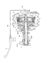
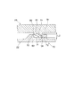
図1は、本発明の第1実施形態に係るクラッチ装置を周辺構成と共に示す図である。また、図2〜図5は、クラッチ装置の側断面図を示している。
このクラッチ装置10は、自動二輪車(不図示)のエンジンのクランクシャフト(不図示)から変速機100の主軸を構成するメインシャフト1へ向かう回転動力伝達経路上に設置され、運転者のクラッチ操作に応じて回転動力(トルク)の伝達を遮断及び接続させるものである。
すなわち、自動二輪車には、エンジンの一部を構成するクランクケース2内に、クランクシャフト、メインシャフト及びカウンタシャフト(不図示)が回転自在に支持されており、クランクシャフトには、ドライブギヤが設けられており、メインシャフト1には、図1に示すように、このシャフト1にスリーブ4を介して回転自在に支承されてドライブギヤに噛み合うドリブンギヤ5が設けられている。そして、このドリブンギヤ5とメインシャフト1との間にクラッチ装置10が構成されている。なお、図1中、符号6、7は、メインシャフト1をクランクケース2の壁2A、2Bに回転自在に支持するための左右一対の軸受である。
Hereinafter, an embodiment of the present invention will be described with reference to the accompanying drawings.
<First Embodiment>
FIG. 1 is a view showing a clutch device according to a first embodiment of the present invention together with peripheral components. 2 to 5 show side sectional views of the clutch device.
The
That is, in a motorcycle, a crankshaft, a main shaft, and a countershaft (not shown) are rotatably supported in a
また、自動二輪車の変速機100は、メインシャフト1及びカウンタシャフトに嵌め込まれた複数組のギヤからなるギヤ部100Aを備え、運転者のシフト操作に応じていずれかのギヤを介してメインシャフト1の回転をカウンタシャフトに伝達し、所定の変速比でカウンタシャフトを回転駆動して自動二輪車の後輪を回転駆動させ、これによって、シフト操作に応じて伝達ギヤを切り換えて変速比を変更する。
また、自動二輪車には、図示せぬハンドルにクラッチレバー(手動操作子)11が設けられ、このクラッチレバー11が操作されると(引かれると)、クラッチ装置10がドリブンギヤ5からメインシャフト1への動力伝達を遮断し、カウンタシャフト及び後輪への動力伝達を遮断する。ここで、この自動二輪車においては、従来の一般的な自動二輪車と同様に、メインシャフト1が車両の進行方向に対して直角方向にレイアウトされ、つまり、車幅方向に沿ってレイアウトされている。なお、図中、符号Rは、車両に乗車した運転者から見た右方向(車体右側)を示している。
The
The motorcycle is provided with a clutch lever (manual operation element) 11 on a handle (not shown). When the
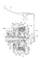
図2に示すように、クラッチ装置10は、メインシャフト1の軸受7よりも外側(図中R側)に延長する軸端部1Aに配設されている。
クラッチ装置10は、入力部材であるドリブンギヤ5に連結されるクラッチアウタ21と、出力部材であるメインシャフト1と一体に回転するクラッチインナ22と、クラッチアウタ21の内周面に相対回転不能に係合される複数のフリクションプレート(第1摩擦板)23と、フリクションプレート23に交互に重ねられ、クラッチインナ22の内周面に相対回転不能に係合される複数のクラッチプレート(第2摩擦板)24と、フリクションプレート23とクラッチプレート24とを圧接させる第1プレッシャプレート(手動側押圧部材)25と、第1プレッシャプレート25をクラッチレバー11の操作に応じて移動させてクラッチ接続(動力伝達状態)を断続させる手動式レリーズ機構26と、第1プレッシャプレート25と対でクラッチ接続を保持させる第2プレッシャプレート(遠心側押圧部材)27とを備えている。
As shown in FIG. 2, the
The
クラッチアウタ21は、軽量金属材料であるアルミニウム合金で製造され、ドリブンギヤ5にリベット31によって連結される略円板状の基部21Aと、この基部21Aからメインシャフト1の軸方向(図中R方向)に略筒状に延びる延長筒部21Bとを有し、この延長筒部21Bの内側に、複数のフリクションプレート23がメインシャフト1の軸方向に移動自在に相対回転不能に係合される。このクラッチアウタ21は、ドリブンギヤ5に連結されるため、ドリブンギヤ5と一体に回転する。また、ドリブンギヤ5とクラッチアウタ21の基部21Aとの間には、ドリブンギヤ5とクラッチアウタ21との間の伝達力の急激な立ち上がりを緩和するダンパースプリング32が配置されると共に、ドリブンギヤ5に対してクラッチアウタ21を軸方向に付勢してクラッチアウタ21を位置決め等するための皿ばね33とが配置されている。
The clutch outer 21 is made of an aluminum alloy, which is a lightweight metal material, and is connected to the driven
クラッチインナ22は、SCM浸炭鋼で製造され、出力部材であるメインシャフト1にスプライン結合される略円板状のクラッチセンタ22Aと、このクラッチセンタ22Aの外周部から軸方向前後に延びるクラッチピストン22Bとを備えている。このクラッチインナ22は、メインシャフト1にスプライン結合されるため、メインシャフト1に対して相対回転不能かつ軸方向に自在である。
このクラッチインナ22は、メインシャフト1に対してスリーブ4の後に挿入され、クラッチアウタ21の延長筒部21Bの内側にレイアウトされ、このクラッチインナ22の外周面(クラッチピストン22Bの外周面)に、クラッチアウタ21の延長筒部21Bに設けられた複数のフリクションプレート23と軸方向に交互に配置される複数のクラッチプレート24が相対回転不能に係合される。
メインシャフト1には、このクラッチインナ22を挿入した後、スペーサ8を介してナット9を締結することによって、スリーブ4及びクラッチインナ22の位置決め及び抜け止めが行われる。この場合、図示のように、メインシャフト1の端部がクラッチインナ22のクラッチピストン22B内側にレイアウトされるため、クラッチピストン22B内側のスペースを有効利用してスペーサ8及びナット9がレイアウトされ、メインシャフト1の軸方向(R側)への大型化を回避できる。
The clutch inner 22 is made of SCM carburized steel, and is a substantially disc-shaped
The clutch inner 22 is inserted behind the
After the clutch inner 22 is inserted into the
このメインシャフト1は、軸方向に中空孔1Cを有する中空シャフトに形成されており、このメインシャフト1の中空孔1Cには、リフターピース35が軸方向にスライド自在に挿入され、このリフターピース35にレリーズ軸受36を介して第1プレッシャプレート25が回転自在に支持されている。
この第1プレッシャプレート25は、軽量金属材料であるアルミニウム合金で製造された略円板状に形成され、クラッチインナ22に対して車体外側(R側)にレイアウトされ、フリクションプレート23とクラッチプレート24とを圧接する側に押圧する押圧部材(手動側押圧部材)として機能する。
The
The
より具体的には、第1プレッシャプレート25は、クラッチアウタ21の延長筒部21Bの内径よりも小径に形成されてクラッチアウタ21の延長筒部21Bの内側に入り込むようにレイアウトされる。また、フリクションプレート23に対向する外周部25Aがフリクションプレート23側に向けて略L字状に屈曲するL字断面形状に形成され、この外周部25Aの背面に形成された段差部25Bと、クラッチアウタ21の延長筒部21Bに設けられたサークリップ(つば部)38との間に、フリクションプレート23とクラッチプレート24とが圧接する側に第1プレッシャプレート25を付勢するクラッチスプリング39が配置される。すなわち、第1プレッシャプレート25の外周部25Aにクラッチインナ22側に凹む段差部25Bを形成し、この段差部25Bをクラッチスプリング39で押圧するように構成することで、クラッチスプリング39をクラッチインナ22寄りに配置でき、その分、メインシャフト1の軸方向(R側)への大型化を回避できる。
More specifically, the
上記リフターピース35の第1プレッシャプレート25よりも車体外側(R側)には、環状凹部35Aが設けられ、この環状凹部35Aには、アーム部41の先端に設けられたクラッチ作動シャフト42の爪部42Aが引っ掛けられる。このアーム部41は、端部金具43を介してクラッチケーブル44が連結され、このクラッチケーブル44の他端にクラッチレバー11が連結される。そして、図3に示すように、クラッチレバー11が矢印A方向に操作されると(引かれると)、クラッチケーブル44が矢印B方向に引かれてアーム部41が矢印C方向(図中反時計回り方向)に回動する。
図3に示すように、アーム部41が矢印C方向へ回動すると、クラッチ作動シャフト42が矢印D方向に回動し、クラッチ作動シャフト42の爪部42Aがリフターピース35を矢印E方向に移動し、第1プレッシャプレート25を図中R方向(=矢印E方向)に移動させる。
このようにして第1プレッシャプレート25がクラッチスプリング39の付勢力に抗して図中R方向に移動させられると、フリクションプレート23とクラッチプレート24との圧接力が弱められて摩擦係合が解除し、クラッチアウタ21とメインシャフト1との間の動力伝達(トルク伝達)が遮断される。これによって、第1プレッシャプレート25をクラッチレバー11の操作に連動させて動力伝達を遮断する手動式レリーズ機構26が構成される。
なお、クラッチレバー11の操作をクラッチケーブル44を介して手動式レリーズ機構26に伝える場合について説明したが、これに限らず、油圧によって伝えても良く、また、手動式レリーズ機構26も上記のカム式に限らず、ラック&ピニオン式等の他の方式を適用してもよい。
An
As shown in FIG. 3, when the
When the
Although the case where the operation of the
図2に示すように、第2プレッシャプレート27は、第1プレッシャプレート25との間にフリクションプレート23とクラッチプレート24とを挟持するように第1プレッシャプレート25の他側に設けられている。より具体的には、第2プレッシャプレート27は、クラッチアウタ21とクラッチインナ22との間のスペース内に収まるように、スリーブ4の外周に軸方向に移動自在に設けられ、メインシャフト1に対して相対回転自在である。この第2プレッシャプレート27は、軽量金属材料であるアルミニウム合金で製造され、メインシャフト1に挿入されたスリーブ4に遊嵌される略筒状の基部27Aと、この基部27Aから外周方向へ延びる略円板状のプレート本体27Bとを有し、この第2プレッシャプレート27の外径が、クラッチアウタ21の延長筒部21Bの内径よりも小径に形成されることによって、クラッチアウタ21の延長筒部21Bの内側であって、クラッチアウタ21の基部21Aとクラッチインナ22のクラッチセンタ22Aとの間の狭いスペース内に軸方向に移動自在に配置される。
As shown in FIG. 2, the
また、この第2プレッシャプレート27のプレート本体27Bとクラッチセンタ22Aとの間には、皿ばねからなるリターンスプリング45が介挿され、このリターンスプリング45によって、第2プレッシャプレート27がクラッチインナ22から離間する側(R方向の逆方向)へ付勢される。ここで、第2プレッシャプレート27のプレート本体27Bには、メインシャフト1と同軸でクラッチインナ22のクラッチセンタ22A側に向けて突出する外周円形の突出部27Cが一体に形成され、この突出部27Cの外周側にスラスト軸受46が取り付けられ、このスラスト軸受46を介してリターンスプリング45が接触する。このように第2プレッシャプレート27とリターンスプリング45との間にスラスト軸受46を配置したので、リターンスプリング45の付勢力を確実に第2プレッシャプレート27に作用させることができ、かつ、第2プレッシャプレート27とクラッチセンタ22Aとの間に回転差が生じた場合でも、第2プレッシャプレート27とリターンスプリング45との間に生じる回転摩擦を回避することができる。
A
この第2プレッシャプレート27とクラッチアウタ21の基部21Aとの間には、複数個の遠心ウエイト51がメインシャフト1の周方向に間隔を空けて配置され、これら遠心ウエイト51は、エンジンの回転と共に回転するクラッチアウタ21に設けられた半径方向に延在する傾斜溝部21Sに各々収容されてクラッチアウタ21と一体に回転する。また、各遠心ウエイト51をリターンスプリング45の付勢力によって付勢する第2プレッシャプレート27にも、各遠心ウエイト51を半径方向に案内する溝部27Sが設けられ、この遠心ウエイト51を介してクラッチアウタ21と一体に回転するようになっている。
A plurality of
上記のように、各遠心ウエイト51には、第2プレッシャプレート27を介してリターンスプリング45の付勢力が作用するので、エンジンがアイドリング回転数程度の低回転(エンジン停止中を含む)の場合、各遠心ウエイト51が傾斜溝部21Sの傾斜面に案内されてメインシャフト1側(内周側)へと移動し、傾斜溝部21Sの最も内周側に位置する(図2参照)。この場合、第2プレッシャプレート27が、フリクションプレート23とクラッチプレート24とを圧接させない位置(以下、非押圧位置という)へと移動し、これらプレート23、24を摩擦係合させず、動力伝達を遮断した状態に保持する。すなわち、エンジン低回転の場合、第2プレッシャプレート27は、リターンスプリング45の付勢力によりクラッチを切断する位置に保持される。
As described above, since the urging force of the
一方、エンジン回転数が上昇すると、このエンジンの回転による遠心力が各遠心ウエイト51に作用するため、遠心ウエイト51に作用する遠心力がリターンスプリング45の付勢力を超えると、図4に示すように、各遠心ウエイト51が、リターンスプリング45の付勢力に抗してメインシャフト1の半径方向(外周側)へと移動する。
この場合、遠心ウエイト51が傾斜溝部21Sの傾斜面に沿って移動するので、第2プレッシャプレート27をフリクションプレート23側へ押し出して、フリクションプレート23とクラッチプレート24とを圧接させる側(以下、押圧位置という)へと移動させ、プレート23、24を摩擦係合させて動力伝達状態に切り換える(図4参照)。これによって、この遠心ウエイト51の作用によりクラッチ接続を断続させる遠心クラッチ機構55が構成される。
ここで、本構成では、第2プレッシャプレート27のプレート本体27Bとクラッチプレート24との間に、ジャダースプリング及びスプリングシートからなるスプリング部材28を介挿している。このため、このスプリング部材28により、遠心クラッチ機構55のクラッチ接続時(本実施形態では遠心クラッチ接続時)に出る振動(いわゆるジャダー)を回避することが可能である。
On the other hand, when the engine speed increases, the centrifugal force due to the rotation of the engine acts on each
In this case, since the
Here, in this configuration, a
このように、エンジンが低回転(アイドリング回転やエンジン停止を含む)の場合は、第2プレッシャプレート27がリターンスプリング45の付勢力によってクラッチ接続を遮断する非押圧位置に移動するので、クラッチレバー11の操作の有無に関係なく、メインシャフト1への動力伝達(トルク伝達)が遮断される。
これに対し、エンジンが運転されて遠心ウエイト51に作用する遠心力がリターンスプリング45の付勢力を超えると、第2プレッシャプレート27がクラッチ接続する押圧位置へと移動するので、クラッチレバー11が操作されていない場合、つまり、手動でクラッチ接続が遮断されていない場合には、メインシャフト1への動力伝達(トルク伝達)を行うクラッチ接続状態に切り換えることができる。
従って、例えば、エンジン回転数をアイドリング回転数から徐々に上げていくと、自動でクラッチ接続され、運転者によるクラッチ操作無しで自動二輪車を発進させることが可能になり、一方、エンジン回転数が高い状態からアイドリング回転数程度まで下げていくと、自動でクラッチ接続が遮断され、クラッチ操作無しでクラッチ接続を遮断する(クラッチを切る)ことができる。
Thus, when the engine is running at a low speed (including idling rotation and engine stop), the
On the other hand, when the engine is operated and the centrifugal force acting on the
Therefore, for example, when the engine speed is gradually increased from the idling speed, the clutch is automatically engaged and the motorcycle can be started without a clutch operation by the driver, while the engine speed is high. When the state is lowered to about the idling speed, the clutch connection is automatically disconnected, and the clutch connection can be disconnected (disengaged) without clutch operation.
一方、遠心クラッチ機構55が作動している場合(遠心クラッチ接続状態の場合)でも、クラッチレバー11が操作されると(引かれると)、図3に示すように、第1プレッシャプレート25を強制移動してフリクションプレート23とクラッチプレート24との摩擦係合が解除されるので、メインシャフト1への動力伝達を遮断でき、つまり、クラッチ接続を解除することができる。
従って、クラッチレバー11を操作しなければ、エンジン回転数に応じて自動でクラッチ接続/遮断を切り換えるいわゆる自動クラッチの状態にすることができ、クラッチレバー11を操作すれば、従来の手動クラッチと同様に任意のタイミングでクラッチ遮断することが可能になり、クラッチ操作を自動と手動とに容易に切り換えることができる。
On the other hand, even when the centrifugal
Therefore, if the
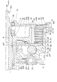
また、本構成のクラッチアウタ21は、図2に示すように、第1プレッシャプレート25の縁部に対向する部分が第1プレッシャプレート25側に突出することにより、エンジンが低回転で遠心クラッチ機構55がクラッチ遮断状態の場合に、クラッチスプリング39で付勢される第1プレッシャプレート25の縁部が当接する当接部21Cが一体に形成されている。このため、遠心クラッチ非接続状態のときは、第1プレッシャプレート25とクラッチアウタ21とが当接し、第1プレッシャプレート25の当接時の位置のばらつきを小さくすることができる。なお、遠心クラッチ接続状態のときは、図5に示すように、第2プレッシャプレート27が軸方向(R方向)へと移動し、フリクションプレート23及びクラッチプレート24を介して第1プレッシャプレート25を軸方向(R方向)へと移動させるので、第1プレッシャプレート25とクラッチアウタ21との間に隙間L1が形成される。また、上記当接部21Cは、クラッチアウタ21の全周に渡って設けてもよいし、所定の間隔を空けて周方向に複数設けるようにしてもよい。
また、この遠心クラッチ機構55では、図5に示すように、遠心ウエイト51による押付力が回転数上昇により要求押付力以上に高くなりすぎないように、クラッチアウタ21側に、遠心ウエイト51の径方向への移動を規制するウエイトローラストッパ21Pを設置又は、クラッチセンタ22A側に、第2プレッシャプレート27の移動を規制するストッパ22Pを設置して押付力が適正となるように制御している。また、ディスク倒れ防止のため、第2プレッシャプレート27とドリブンギヤ5の内周筒部との間にガイド(インロー:第2プレッシャプレート27の倒れ等を回避可能な適正量のすきまとガイド長さ)をもたせている。
Further, as shown in FIG. 2, the clutch outer 21 of this configuration has a centrifugal clutch mechanism with a low rotation speed because the portion facing the edge of the
Further, in the centrifugal
以上説明したように、本実施形態のクラッチ装置10では、クラッチレバー11の操作に応じて移動する第1プレッシャプレート25の他側に、エンジンの回転による遠心力で移動する遠心ウエイト51により作動する第2プレッシャプレート27を設けて遠心クラッチ機構55を形成したので、クラッチ操作を手動と自動とに任意に選択可能な遠心式・手動式一体クラッチを構成することができる。これにより、走行中の駆動力調整、動力伝達の断続、及び、エンジンブレーキ調整を運転者が任意に行うことができる手動クラッチの利点と、発進と停止を頻繁に繰り返す走行状況での操作上の煩わしさのない自動クラッチの利点との両方を具備したクラッチ装置にすることができる。
As described above, in the
しかも、本構成では、第2プレッシャプレート27を、第1プレッシャプレート25の他側に設けたので、第1プレッシャプレート25の他側のスペース、つまり、クラッチアウタ21とクラッチインナ22との間の空きスペースを有効利用して第2プレッシャプレート27をレイアウトでき、装置全体の大型化(メインシャフト1の軸方向及び径方向への大型化)を抑制することができる。
より具体的には、この第2プレッシャプレート27を、メインシャフト1側(スリーブ4)に配設すると共に、クラッチアウタ21の延長筒部21Bの内径よりも小径に形成したため、クラッチアウタ21の延長筒部21Bの内側であって、かつ、クラッチアウタ21の基部21Aとクラッチインナ22のクラッチセンタ22Aとの間の狭いスペース内に効率よくレイアウトでき、クラッチアウタ21やクラッチインナ22に、第2プレッシャプレート27との干渉等を避けるための逃げ部を形成する必要がなく、各部品の形状の複雑化及び大型化を回避することができる。
In addition, in this configuration, since the
More specifically, the
また、本構成では、クラッチアウタ21に、遠心クラッチ非接続状態のときに第1プレッシャプレート25が当接する当接部21Cを設けたので、第1プレッシャプレート25の当接時の位置のばらつきを小さくすることができる。
また、本構成では、第2プレッシャプレート27を遠心ウエイト51側に押圧するリターンスプリング45を、クラッチインナ22のクラッチセンタ22Aの内周に位置するように設けたので、フリクションプレート23及びクラッチプレート24のレイアウトに影響を与えることなく、リターンスプリング45をレイアウトできる。このため、仮に摩擦板(フリクションプレート23、クラッチプレート24に相当)外側にリターンスプリングを設けた場合には、リターンスプリングのレイアウトスペースを確保するために摩擦板の径方向の大きさ(最大径等)を小さくしなければならない制約が生じるが、本構成では、このような制約が生じない利点がある。
しかも、本構成のリターンスプリング45は、クラッチセンタ22Aと第2プレッシャプレート27との間に設けた皿ばねであるため、リターンスプリング45のサイズを小さくでき、クラッチセンタ22Aと第2プレッシャプレート27との間の空きスペースを有効利用して装置全体をより小型化できる。
なお、上述したクラッチアウタ21、クラッチインナ22、フリクションプレート23、クラッチプレート24、第1プレッシャプレート25及び第2プレッシャプレート27等は上述した材料に限らず、いずれもアルミニウム合金、鉄素材等の剛性材料を広く適用可能である。
Further, in this configuration, the clutch outer 21 is provided with the abutting
Further, in this configuration, the
Moreover, since the
The clutch outer 21, the clutch inner 22, the
<第2実施形態>
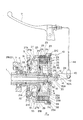
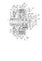
図6は第2実施形態に係るクラッチ装置10を示す。
このクラッチ装置10には、第1プレッシャプレート25とクラッチインナ22とにクラッチ装置10が回転動力伝達(トルク伝達)する際に互いに噛み合うカム71、72が設けられており、これらカム71、72により第1プレッシャプレート25をメインシャフト1の軸方向に移動させてフリクションプレート23とクラッチプレート24との摩擦係合力を調整するカム機構70が構成されている。
<Second Embodiment>
FIG. 6 shows a
The
詳述すると、カム機構70は、クラッチインナ22側に突出するように第1プレッシャプレート25に設けられる複数の凸状カム71と、第1プレッシャプレート25側に突出するようにクラッチインナ22に設けられ、凸状カム71が挿入される複数の凹状カム72とを備えている。
これら凸状カム71及び凹状カム72は、第1プレッシャプレート25及びクラッチインナ22の周方向に間隔を空けて設けられ、例えば、120度間隔で設けた場合には3個ずつ配設される。また、図6では、これらカム71、72を第1プレッシャプレート25及びクラッチインナ22に一体に形成した場合を示しているが、これに限らず、これらカム71、72を第1プレッシャプレート25及びクラッチインナ22とは別体の部品で構成し、これら別体部品を圧入等で連結して第1プレッシャプレート25及びクラッチインナ22に連結するようにしてもよい。
More specifically, the
The
図7は、凸状カム71及び凹状カム72を周辺構成と共に示す断面図である。
凸状カム71の周方向外端面には、周方向に対し同一方向に傾斜する第1傾斜面81及び第2傾斜面82がそれぞれ形成され、凹状カム72の周方向内端面にも、周方向に対し同一方向に傾斜する第1傾斜面61及び第2傾斜面62がそれぞれ形成されている。ここで、凹状カム72の径方向外端側は開放されている。なお、この凹状カム72の開放は、本実施形態では、径方向外端側に設けられるが、径方向内端側に設けられても径方向両端側に設けられていてもよい。
凸状カム71の第1傾斜面81は、メインシャフト1から逆駆動力(バックトルク)が作用した時に凹状カム72の第1傾斜面91に当接する。各傾斜面81、91は互いに当接した場合に、第1プレッシャプレート25をクラッチインナ22から離間する側へ移動させるカム面に形成されている。すなわち、メインシャフト1から逆駆動力が作用した時に、第1プレッシャプレート25をクラッチインナ22から離間する側へ移動させれば、フリクションプレート23とクラッチプレート24との摩擦係合力を低下させてクラッチ容量を減少させることができる。
FIG. 7 is a sectional view showing the
A first
The first
また、凸状カム71の第2傾斜面82は、ドリブンギヤ5から駆動力が作用した時に凹状カム72の第2傾斜面92に当接する。これらの傾斜面82、92は互いに当接した場合に、第1プレッシャプレート25をクラッチインナ22に近接する側へ移動させるカム面に形成されている。すなわち、ドリブンギヤ5から駆動力が作用した時に、第1プレッシャプレート25をクラッチインナ22に近接する側へ移動させれば、フリクションプレート23とクラッチプレート24との摩擦係合力を増加させてクラッチ容量を増加させることができる。
Further, the second
このように、本実施形態のクラッチ装置10では、第1プレッシャプレート25とクラッチインナ22(より具体的にはクラッチセンタ22A)とにカム71、72を設け、これらカム71、72により、メインシャフト1から逆駆動力(バックトルク)が作用した場合に、第1プレッシャプレート25をフリクションプレート23とクラッチプレート24との摩擦係合力を低下させる側へ移動させると共に、ドリブンギヤ5から駆動力が作用した場合に、第1プレッシャプレート25をフリクションプレート23とクラッチプレート24との摩擦係合力を増加させる側へ移動させるカム機構70を設けている。
この構成によれば、このカム機構70を、第1プレッシャプレート25とクラッチインナ22(クラッチセンタ22A)との間の空きスペースを有効利用して設けることができ、装置全体の大型化を回避することができ、本例では、第1実施形態のクラッチ装置とほぼ同じ大きさにすることが可能である。また、上記第1実施形態のクラッチ装置に対して、上記カム71、72を追加するだけの小変更でカム機構70を容易に追加できる。これにより、いわゆるアシスト・スリッパーの機能を備えた遠心式・手動式一体クラッチを簡易に構成することが可能になる。
As described above, in the
According to this configuration, the
また、本構成では、上記カム機構70を、遠心クラッチ機構55側ではなく、手動クラッチ機構側に設けている。その理由は、仮にカム機構70を遠心クラッチ機構55側に設けた場合には、遠心クラッチ機構55はエンジン回転による遠心力を利用するため、エンジン回転数が高いと、フリクションプレート23とクラッチプレート24との摩擦係合力を低下させるにはスラスト方向に強い力が必要となり、メインシャフト1からの逆駆動力の伝達を大きく低減させるのが難しくなってしまう。これに対し、カム機構70を手動クラッチ機構側に設けた場合には、エンジン回転数が高くても遠心力に影響されないため、メインシャフト1からの逆駆動力の伝達をより低減させることができるからである。
In this configuration, the
また、本構成では、図6に示すように、第1プレッシャプレート25の段差部25Bにスラスト軸受を取り付け、このスラスト軸受に、クラッチスプリング39が接触するように構成している。これによれば、クラッチスプリング39の付勢力を確実に第1プレッシャプレート25に作用させることができ、かつ、カム機構70の作動により第1プレッシャプレート25とクラッチアウタ21との間に回転差が生じた場合でも、スラスト軸受によりクラッチスプリング39に回転摩擦が作用する事態を回避することができる。
In this configuration, as shown in FIG. 6, a thrust bearing is attached to the
さらに、本構成では、凸状カム71の第1傾斜面81及び第2傾斜面82を単純平面の傾斜面にするのではなく、軸方向に対する傾斜角度が変化する曲面形状であって、径方向に対する傾斜角度は変化しない曲面形状に形成しており、具体的には、凸状カム71を回転方向の前後に膨出させる所定の曲率R1を有する曲面に形成している。例えば、この曲率R1は、凸状カム71の軸方向長さL2の略10倍に設定される。この場合、凸状カム71の第1及び第2傾斜面81、82は、ワークと回転工具とを平行軸上で同一方向に回転させて回転工具でワークを断続切削するポリゴン加工により形成される。
一方、さらに、凹状カム72の第1傾斜面91及び第2傾斜面92は、径方向に対する傾斜角度が変化する曲面形状であって、軸方向に対する傾斜角度は変化しない曲面形状(図7参照)に形成しており、具体的には、径方向に所定の曲率R2(不図示)を有する曲面に形成し、例えば、この凹状カム72の第1傾斜面91及び第2傾斜面92は、ドリルなどの切削用工具やワークの動作を座標値によって制御・動作させて切削用工具でワークを切削するNC加工により形成される。
Furthermore, in this configuration, the first
On the other hand, the first
このように、凸状カム71の第1及び第2傾斜面81、82を軸方向に対する傾斜角度が変化する曲面形状にし、かつ、凹状カム72の第1及び第2傾斜面91、92を径方向に対する傾斜角度が変化する曲面形状にした場合、凸状カム71の第1傾斜面81と凹状カム72の第1傾斜面91との接触を点接触にすることができると共に、凸状カム71の第2傾斜面82と凹状カム72の第2傾斜面92との接触についても点接触にすることができる。
このように点接触させた場合、凸状カム71及び凹状カム72の加工精度にバラツキが生じたとしても、凸状カム71及び凹状カム72の接触面積が変化することがないので、クラッチ容量の可変特性が一定に確保される。また、凸状カム71及び凹状カム72の加工精度のばらつきが許容されるため、高い加工精度を有する工作機械や、加工後の管理基準を厳しく設定した生産管理体制が不要となるので、クラッチ装置10の製造コストを削減することが可能となる。
As described above, the first and second
In such a point contact, even if the processing accuracy of the
なお、この実施形態では、カム機構70を構成する一対の凸状カム71及び凹状カム72のカム面のいずれも曲面に形成する場合について説明したが、これに限らず、いずれか一方あるいは両方のカム面を平面にしてもよく、凸状カム71及び凹状カム72を点接触させる構成に限らず、線接触、或いは、面接触させる従来のカム形状を適用してもよい。
In this embodiment, a case has been described in which both the cam surfaces of the pair of
以上、一実施形態に基づいて本発明を説明したが、本発明はこれに限定されるものでなく、種々の設計変形を行うことが可能である。例えば、上述の各実施形態では、クラッチスプリング39に皿ばねを用いた遠心式・手動式一体クラッチを構成する場合について説明したが、これに限らず、例えば、図8に示すように、クラッチスプリング39にコイルばねを使用した遠心式・手動式一体クラッチ装置を構成することも可能である。
Although the present invention has been described based on one embodiment, the present invention is not limited to this, and various design modifications can be made. For example, in each of the above-described embodiments, the case where a centrifugal / manual integrated clutch using a disc spring is used as the
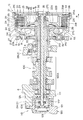
また、上述の各実施形態において、図9に例示する油圧機構110によってクラッチ接続を断続させるようにしてもよい。詳述すると、この油圧機構110は、メインシャフト1内を軸方向に移動自在に通されたプッシュロッド111と、このプッシュロッド111を作動させる油圧シリンダ120と、油圧シリンダ120に油圧を供給するアクチュエータ(不図示)とを備えている。油圧シリンダ120は、クランクケース2の壁2Aに取り付けられたシリンダ本体121と、このシリンダ本体121に移動自在に挿入されてアクチュエータから供給される油圧で移動するピストン122と、ピストン122をプッシュロッド111に押し付けるスプリング123と、パッキン124、125とを備えて構成されている。この構成によれば、アクチュエータから供給される油圧でピストン122を移動することによって、プッシュロッド111を油圧駆動し、このプッシュロッド111によりリフターピース35を移動して手動クラッチの断続を行うことができる。
Further, in each of the above-described embodiments, the clutch connection may be intermittently connected by the
また、上述の各実施形態において、遠心ウエイト51には円筒形状、球形状、或いは振り子形状等を広く適用可能であり、クラッチ装置10の設置箇所はメインシャフト1に限らず、クランクシャフトやその他の中間軸でも可能である。また、クラッチの手動操作子は、クラッチレバー11に限らず、クラッチペダル等の他の操作子であってもよい。
さらに、上述の各実施形態では、本発明を自動二輪車のクラッチ装置に適用する場合について説明したが、これに限らず、ATV(不整地走行車両)、MUV(マルチ・ユーティリティ・ビークル)及びゴルフカート等に分類される三輪車両や四輪車両等の他の車両のクラッチ装置に適用することも可能である。
Further, in each of the above-described embodiments, the
Further, in each of the above-described embodiments, the case where the present invention is applied to a clutch device for a motorcycle has been described. However, the present invention is not limited to this, and is not limited thereto. It is also possible to apply to clutch devices of other vehicles such as three-wheeled vehicles and four-wheeled vehicles classified into the above.
1 メインシャフト
5 ドリブンギヤ
10 クラッチ装置
11 クラッチレバー(手動操作子)
21 クラッチアウタ
22 クラッチインナ
22A クラッチセンタ
23 フリクションプレート(第1摩擦板)
24 クラッチプレート(第2摩擦板)
25 第1プレッシャプレート(手動側押圧部材)
26 手動式レリーズ機構
27 第2プレッシャプレート(遠心側押圧部材)
39 クラッチスプリング
45 リターンスプリング
51 遠心ウエイト
55 遠心クラッチ機構
70 カム機構
71 凸状カム
72 凹状カム
100 変速機
110 油圧機構
1
21 Clutch outer 22 Clutch inner 22 A
24 Clutch plate (second friction plate)
25 First pressure plate (manual pressure member)
26
39
Claims (5)
このクラッチアウタの内部に配置され、前記複数の第1摩擦板の間に配置される複数の第2摩擦板が外周面に相対回転不能に係合されると共に、出力部材と一体に回転するクラッチインナと、
前記第1及び第2摩擦板を圧接させて前記入力部材から前記出力部材へのトルク伝達を可能とする手動側押圧部材と、
手動操作子の操作に応じて前記手動側押圧部材を移動させて前記トルク伝達を断続させる手動式レリーズ機構とを備えるクラッチ装置において、
前記手動側押圧部材の他側に設けられ、前記エンジンの回転による遠心力で移動する遠心ウエイトにより作動する遠心側押圧部材を備え、エンジン回転数が上昇すると前記遠心ウエイトが遠心力により前記遠心側押圧部材に作用して前記トルク伝達を可能とする遠心クラッチ機構を備えたことを特徴とするクラッチ装置。 A clutch outer coupled to an input member driven by an engine and having a plurality of first friction plates engaged with an inner peripheral surface in a relatively non-rotatable manner;
A clutch inner disposed inside the clutch outer and being engaged with the outer peripheral surface so as not to rotate relative to the outer peripheral surface and rotating integrally with the output member; ,
A manual-side pressing member that presses the first and second friction plates to enable torque transmission from the input member to the output member;
In a clutch device including a manual release mechanism that moves the manual side pressing member according to an operation of a manual operation element to interrupt the torque transmission,
A centrifugal side pressing member is provided on the other side of the manual side pressing member and is operated by a centrifugal weight that is moved by a centrifugal force generated by the rotation of the engine. When the engine speed increases, the centrifugal weight is A clutch device comprising a centrifugal clutch mechanism that acts on a pressing member to enable transmission of the torque.
前記クラッチアウタは、前記遠心クラッチ機構が前記トルク伝達を遮断状態のときに前記手動側押圧部材が当接する当接部を有することを特徴とするクラッチ装置。 The clutch device according to claim 1,
The clutch outer has a contact portion with which the manual side pressing member abuts when the centrifugal clutch mechanism is in a state of interrupting the torque transmission.
前記クラッチインナは、前記手動側押圧部材と前記遠心側押圧部材との間に位置するクラッチセンタを備え、前記遠心側押圧部材を前記遠心ウエイト側に押圧するリターンスプリングを、前記クラッチセンタの内周に位置するように設けたことを特徴とするクラッチ装置。 The clutch device according to claim 1 or 2,
The clutch inner includes a clutch center positioned between the manual-side pressing member and the centrifugal-side pressing member, and a return spring that presses the centrifugal-side pressing member toward the centrifugal weight side has an inner periphery of the clutch center. A clutch device provided to be located at
前記リターンスプリングを、皿ばねとし、前記クラッチセンタと前記遠心側押圧部材との間に設けたことを特徴とするクラッチ装置。 In the clutch device according to claim 3,
The clutch device according to claim 1, wherein the return spring is a disc spring and is provided between the clutch center and the centrifugal side pressing member.
前記手動側押圧部材と前記クラッチセンタとに、前記トルク伝達の際に互いに噛み合うカムを設け、これらカムにより、前記出力部材からバックトルクが作用した場合に、前記手動側押圧部材を前記第1摩擦板と前記第2摩擦板との摩擦係合力を低下させる側へ移動させ、前記入力部材から駆動トルクが作用した場合に、前記手動側押圧部材を前記第1摩擦板と前記第2摩擦板との摩擦係合力を低下させる側へ移動させるカム機構を構成したことを特徴とするクラッチ装置。 The clutch device according to claim 3 or 4,
The manual side pressing member and the clutch center are provided with cams that mesh with each other when the torque is transmitted, and when the back torque is applied from the output member by these cams, the manual side pressing member is moved to the first friction. When the drive torque is applied from the input member when the frictional engagement force between the plate and the second friction plate is reduced and the drive torque is applied from the input member, the manual friction member is moved to the first friction plate and the second friction plate. A clutch device characterized in that a cam mechanism for moving the friction engagement force to a side to reduce the friction engagement force is configured.
Priority Applications (1)
| Application Number | Priority Date | Filing Date | Title |
|---|---|---|---|
| JP2008228532A JP5208628B2 (en) | 2008-09-05 | 2008-09-05 | Clutch device |
Applications Claiming Priority (1)
| Application Number | Priority Date | Filing Date | Title |
|---|---|---|---|
| JP2008228532A JP5208628B2 (en) | 2008-09-05 | 2008-09-05 | Clutch device |
Publications (2)
| Publication Number | Publication Date |
|---|---|
| JP2010060106A true JP2010060106A (en) | 2010-03-18 |
| JP5208628B2 JP5208628B2 (en) | 2013-06-12 |
Family
ID=42187120
Family Applications (1)
| Application Number | Title | Priority Date | Filing Date |
|---|---|---|---|
| JP2008228532A Expired - Fee Related JP5208628B2 (en) | 2008-09-05 | 2008-09-05 | Clutch device |
Country Status (1)
| Country | Link |
|---|---|
| JP (1) | JP5208628B2 (en) |
Cited By (12)
| Publication number | Priority date | Publication date | Assignee | Title |
|---|---|---|---|---|
| JP2012031901A (en) * | 2010-07-29 | 2012-02-16 | Honda Motor Co Ltd | Clutch system |
| JP2012037020A (en) * | 2010-08-11 | 2012-02-23 | Honda Motor Co Ltd | Clutch device |
| WO2013183588A1 (en) * | 2012-06-04 | 2013-12-12 | 株式会社エフ・シ-・シ- | Power transmission device |
| JP2016205622A (en) * | 2015-04-24 | 2016-12-08 | 楊裕修 | Dry clutch mounted with coaxial fixation surface contact type passive clutch plate |
| WO2018116639A1 (en) * | 2016-12-20 | 2018-06-28 | 株式会社エクセディ | Power transmission device |
| JP2018100699A (en) * | 2016-12-20 | 2018-06-28 | 株式会社エクセディ | Power transmission device |
| WO2020170507A1 (en) * | 2019-02-22 | 2020-08-27 | 本田技研工業株式会社 | Clutch locking mechanism |
| JP2020143758A (en) * | 2019-03-08 | 2020-09-10 | 株式会社エクセディ | Centrifugal clutch and pulley device |
| JP2020143757A (en) * | 2019-03-08 | 2020-09-10 | 株式会社エクセディ | Pulley device |
| CN113167338A (en) * | 2018-12-05 | 2021-07-23 | 株式会社F.C.C. | Power transmission device |
| JP2021183863A (en) * | 2020-05-22 | 2021-12-02 | 株式会社オリジン | Free type bidirectional clutch |
| EP4180680A1 (en) * | 2020-04-13 | 2023-05-17 | Kabushiki Kaisha F.C.C. | Power transmission device |
Citations (5)
| Publication number | Priority date | Publication date | Assignee | Title |
|---|---|---|---|---|
| JPH04357339A (en) * | 1991-06-03 | 1992-12-10 | Yamaha Motor Co Ltd | Multiple disc centrifugal clutch |
| JPH1130248A (en) * | 1997-07-09 | 1999-02-02 | Toyoda Mach Works Ltd | Driving force transmission device |
| JPH11159547A (en) * | 1997-11-28 | 1999-06-15 | Suzuki Motor Corp | Automatic centrifugal clutch device for vehicle |
| JP2003127677A (en) * | 2001-10-19 | 2003-05-08 | Honda Motor Co Ltd | Power transmission device with continuously variable transmission |
| JP2007205387A (en) * | 2006-01-31 | 2007-08-16 | F C C:Kk | Power transmission device |
-
2008
- 2008-09-05 JP JP2008228532A patent/JP5208628B2/en not_active Expired - Fee Related
Patent Citations (5)
| Publication number | Priority date | Publication date | Assignee | Title |
|---|---|---|---|---|
| JPH04357339A (en) * | 1991-06-03 | 1992-12-10 | Yamaha Motor Co Ltd | Multiple disc centrifugal clutch |
| JPH1130248A (en) * | 1997-07-09 | 1999-02-02 | Toyoda Mach Works Ltd | Driving force transmission device |
| JPH11159547A (en) * | 1997-11-28 | 1999-06-15 | Suzuki Motor Corp | Automatic centrifugal clutch device for vehicle |
| JP2003127677A (en) * | 2001-10-19 | 2003-05-08 | Honda Motor Co Ltd | Power transmission device with continuously variable transmission |
| JP2007205387A (en) * | 2006-01-31 | 2007-08-16 | F C C:Kk | Power transmission device |
Cited By (21)
| Publication number | Priority date | Publication date | Assignee | Title |
|---|---|---|---|---|
| US8844698B2 (en) | 2010-07-29 | 2014-09-30 | Honda Motor Co., Ltd. | Centrifugal clutch system |
| JP2012031901A (en) * | 2010-07-29 | 2012-02-16 | Honda Motor Co Ltd | Clutch system |
| JP2012037020A (en) * | 2010-08-11 | 2012-02-23 | Honda Motor Co Ltd | Clutch device |
| US10047803B2 (en) | 2012-06-04 | 2018-08-14 | Kabushiki Kaisha F.C.C. | Power transmitting apparatus |
| WO2013183588A1 (en) * | 2012-06-04 | 2013-12-12 | 株式会社エフ・シ-・シ- | Power transmission device |
| JPWO2013183588A1 (en) * | 2012-06-04 | 2016-01-28 | 株式会社エフ・シー・シー | Power transmission device |
| JP2016205622A (en) * | 2015-04-24 | 2016-12-08 | 楊裕修 | Dry clutch mounted with coaxial fixation surface contact type passive clutch plate |
| WO2018116638A1 (en) * | 2016-12-20 | 2018-06-28 | 株式会社エクセディ | Power transmission device |
| JP2018100700A (en) * | 2016-12-20 | 2018-06-28 | 株式会社エクセディ | Power transmission device |
| WO2018116639A1 (en) * | 2016-12-20 | 2018-06-28 | 株式会社エクセディ | Power transmission device |
| JP2018100699A (en) * | 2016-12-20 | 2018-06-28 | 株式会社エクセディ | Power transmission device |
| CN113167338A (en) * | 2018-12-05 | 2021-07-23 | 株式会社F.C.C. | Power transmission device |
| WO2020170507A1 (en) * | 2019-02-22 | 2020-08-27 | 本田技研工業株式会社 | Clutch locking mechanism |
| US11512746B2 (en) | 2019-02-22 | 2022-11-29 | Honda Motor Co., Ltd. | Clutch locking mechanism |
| JP2020143757A (en) * | 2019-03-08 | 2020-09-10 | 株式会社エクセディ | Pulley device |
| JP2020143758A (en) * | 2019-03-08 | 2020-09-10 | 株式会社エクセディ | Centrifugal clutch and pulley device |
| EP4180680A1 (en) * | 2020-04-13 | 2023-05-17 | Kabushiki Kaisha F.C.C. | Power transmission device |
| EP4191086A1 (en) * | 2020-04-13 | 2023-06-07 | Kabushiki Kaisha F.C.C. | Power transmission device |
| US11703093B2 (en) | 2020-04-13 | 2023-07-18 | Kabushiki Kaisha F.C.C. | Power transmission apparatus |
| JP2021183863A (en) * | 2020-05-22 | 2021-12-02 | 株式会社オリジン | Free type bidirectional clutch |
| JP7143367B2 (en) | 2020-05-22 | 2022-09-28 | 株式会社オリジン | Free type two-way clutch |
Also Published As
| Publication number | Publication date |
|---|---|
| JP5208628B2 (en) | 2013-06-12 |
Similar Documents
| Publication | Publication Date | Title |
|---|---|---|
| JP5208628B2 (en) | Clutch device | |
| US8151963B2 (en) | Power transmitting apparatus | |
| EP3633220B1 (en) | Clutch device | |
| US9341240B2 (en) | Shift device with synchronizer | |
| JP2014156881A (en) | Driving-side pulley | |
| JP2008106846A (en) | Multiple disc type clutch device | |
| JP6289239B2 (en) | Lubrication structure in friction engagement element of automatic transmission for vehicle | |
| US8336695B2 (en) | Power transmitting apparatus | |
| JP2011080496A (en) | Synchronizing device for transmission | |
| US7677124B2 (en) | Transmission of vehicle | |
| CN105987092B (en) | Speed-changing operation device, speed changer and plate | |
| JP2010236653A (en) | Multiplate disc clutch | |
| JP2008057661A (en) | Multiple disc clutch | |
| KR101448394B1 (en) | Clutch actuator for automated manual transmisson | |
| JP2015001269A (en) | Driving side pulley | |
| WO2024009761A1 (en) | Clutch device and motorcycle | |
| JP7252405B1 (en) | Clutch device and motorcycle | |
| JP4502939B2 (en) | Dog clutch | |
| JP2024012030A (en) | Clutch device and motorcycle | |
| JP7474139B2 (en) | Electronic Gear Transmission | |
| WO2024009772A1 (en) | Clutch device | |
| JP2010236569A (en) | Transmission synchronizing device | |
| WO2023238315A1 (en) | Transmission device | |
| JP2018179175A (en) | Structure for preventing falling of annular member in frictional engagement device | |
| JP2010216613A (en) | Driving device for vehicle |
Legal Events
| Date | Code | Title | Description |
|---|---|---|---|
| A621 | Written request for application examination |
Free format text: JAPANESE INTERMEDIATE CODE: A621 Effective date: 20101126 |
|
| A977 | Report on retrieval |
Free format text: JAPANESE INTERMEDIATE CODE: A971007 Effective date: 20120131 |
|
| A131 | Notification of reasons for refusal |
Free format text: JAPANESE INTERMEDIATE CODE: A131 Effective date: 20120207 |
|
| A521 | Written amendment |
Free format text: JAPANESE INTERMEDIATE CODE: A523 Effective date: 20120409 |
|
| RD02 | Notification of acceptance of power of attorney |
Free format text: JAPANESE INTERMEDIATE CODE: A7422 Effective date: 20120409 |
|
| A131 | Notification of reasons for refusal |
Free format text: JAPANESE INTERMEDIATE CODE: A131 Effective date: 20120807 |
|
| A521 | Written amendment |
Free format text: JAPANESE INTERMEDIATE CODE: A523 Effective date: 20121005 |
|
| TRDD | Decision of grant or rejection written | ||
| A01 | Written decision to grant a patent or to grant a registration (utility model) |
Free format text: JAPANESE INTERMEDIATE CODE: A01 Effective date: 20130212 |
|
| A61 | First payment of annual fees (during grant procedure) |
Free format text: JAPANESE INTERMEDIATE CODE: A61 Effective date: 20130220 |
|
| FPAY | Renewal fee payment (event date is renewal date of database) |
Free format text: PAYMENT UNTIL: 20160301 Year of fee payment: 3 |
|
| R150 | Certificate of patent or registration of utility model |
Ref document number: 5208628 Country of ref document: JP Free format text: JAPANESE INTERMEDIATE CODE: R150 Free format text: JAPANESE INTERMEDIATE CODE: R150 |
|
| LAPS | Cancellation because of no payment of annual fees |